on the corrosion resistance of the delhi iron...
TRANSCRIPT

On the corrosion resistance of the Delhi ironpillar
R. Balasubramaniam
Department of Materials and Metallurgical Engineering, Indian Institute of Technology, Kanpur 208 016,
India
Received 19 February 1999; accepted 21 March 2000
Abstract
The nature of the protective passive layer on the corrosion resistant Delhi iron pillar(DIP) has been addressed based on a detailed characterization of its rust. Rustcharacterization clearly established that the major constituents of the scale were crystalline
iron hydrogen phosphate hydrate (FePO4�H3PO4�4H2O), a-, g-, d-FeOOH and magnetite.The iron oxide/oxyhydroxides were present in the amorphous form. The role of slagparticles in the matrix of the DIP iron in enhancing the passive ®lm formation is brie¯yaddressed initially. The process of protective rust formation on DIP iron is outlined based
on the rust analysis. Initially, the corrosion rate of iron is high due to the presence of slagparticles. This results in enhancement of surface P content. In the presence of P, theformation of a protective amorphous compact layer of d-FeOOH, next to the metal surface,
is catalyzed and this confers the initial corrosion resistance. The critical factor contributingto the superior corrosion resistance of the DIP, however, is the formation of iron hydrogenphosphate hydrate, as a thin layer next to the metal±metaloxide interface. The formation of
the crystalline modi®cation of this phosphate from the amorphous form is aided byalternate wetting and drying cycles (i.e. the environmental factor). The rate of corrosion isfurther lowered due to the low porosity content of the crystalline phosphate phase. The
passive ®lm formation on the DIP has been contrasted with the rusting of normal andweathering steels. 7 2000 Elsevier Science Ltd. All rights reserved.
Keywords: Delhi iron pillar; Corrosion resistance; Passive ®lm; Mixed potential theory; Iron hydrogen
phosphate; Microstructure
0010-938X/00/$ - see front matter 7 2000 Elsevier Science Ltd. All rights reserved.
PII: S0010 -938X(00)00046 -9
Corrosion Science 42 (2000) 2103±2129
www.elsevier.com/locate/corsci
1. Introduction
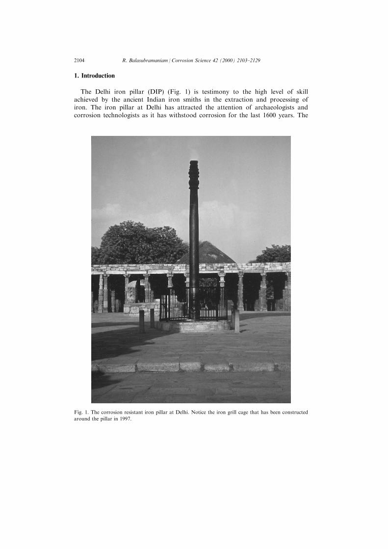
The Delhi iron pillar (DIP) (Fig. 1) is testimony to the high level of skillachieved by the ancient Indian iron smiths in the extraction and processing ofiron. The iron pillar at Delhi has attracted the attention of archaeologists andcorrosion technologists as it has withstood corrosion for the last 1600 years. The
Fig. 1. The corrosion resistant iron pillar at Delhi. Notice the iron grill cage that has been constructed
around the pillar in 1997.
R. Balasubramaniam / Corrosion Science 42 (2000) 2103±21292104

theories that have been proposed to explain its superior corrosion resistance canbe broadly classi®ed into two categories: the environmental [1±3], and material [4±7] theories. These theories have been critically reviewed elsewhere [6,7]. Theproponents of the environmental theory state that the mild climate of Delhi isresponsible for the corrosion resistance of the DIP as the relative humidity atDelhi does not exceed 70% for signi®cant periods of time in the year (Fig. 2),which therefore results in very mild corrosion of the pillar. It is known from theclassic researches of Vernon [8±10] that atmospheric rusting of iron is notsigni®cant for humidity levels less than 70%. Interestingly, the data provided onthe atmospheric conditions at Delhi by Wranglen [2] were collected over a periodof 30 years between 1930 and 1960. It is also important to include the climaticconditions of Delhi over a much longer period, including the recent past, whileanalyzing the environmental e�ect on the pillar's corrosion resistance. Moreover,the climatic conditions of Udayagiri, where the pillar was originally located (itwas brought to Delhi in the 11th century [11]), should also be analyzed in detail.On the other hand, several investigators have stressed the importance of thematerial of construction as the primary reason for its corrosion resistance. Theideas proposed in this regard are the relatively pure composition of the iron used[4], presence of phosphorus and absence of S/Mn in the iron [5], its slag-envelopedmetal grain structure [3], passivity enhancement in the presence of slag particles[6,7] and the formation of phosphate ®lm [5±7]. Other theories explaining thecorrosion resistance are also to be found in the literature like the mass metal e�ect[3,12], initial exposure to an alkaline and ammonical environment [2], residualstresses resulting from the surface ®nishing (hammering) operation [13], freedomfrom sulfur contamination, both in the metal and in the air [13], presence of layersof cinder in the metal, thereby not allowing corrosion to proceed beyond thoselayers (cinder theory) [14], and surface coatings provided to the pillar aftermanufacture (treating the surface with steam [15] and slag coating [16]) andduring use (coating with clari®ed butter) [3]. That the material of constructionmay be an important factor in determining the corrosion resistance of ancientIndian iron is attested by the presence of ancient massive iron objects located inareas where the relative humidity is high for signi®cant periods in the year (forexample, the iron beams in the Surya temple at Konarak in coastal Orissa [17]and the iron pillar at Mookambika temple at Kollur situated in the KodachadriHills on the western coast [18]). It is, therefore, obvious that the ancient Indians,especially from the time of the Guptas (AD300±AD500), produced iron that wascapable of withstanding corrosion. This is primarily due to the high P content ofthe iron produced during ancient times, the reasons for which will be explored indetail later. The known facts about the DIP have also been reviewed in a recentbook [19].
In order to understand the corrosion resistance of the Delhi pillar, it wouldhave been ideal to study the detailed microstructure and passive ®lm formationcharacteristics of metallurgical samples from the DIP. However, this is notpossible, as specimens from the DIP are not available currently. In view of this, anon-corroding iron clamp, produced during the Gupta period (i.e. the time in
R. Balasubramaniam / Corrosion Science 42 (2000) 2103±2129 2105

Fig. 2. Atmospheric conditions at Delhi averaged over 30 years (1930±1960) [2]. The well-known e�ect
of atmospheric humidity on the corrosion of iron [8±10] is also shown below.
R. Balasubramaniam / Corrosion Science 42 (2000) 2103±21292106

which the DIP was constructed), was removed from one of the stone blocks in theruined Gupta temple at Eran, Madhya Pradesh. It exhibited a thin adherentsurface layer. Its microstructure [20], aqueous corrosion behaviour [20], and thenature of its protective rust [21] have been studied earlier in detail. The rust fromthis ancient Indian iron will henceforth be called Eran rust. Rust was alsocollected from several locations in the DIP just below the decorative bell capital(see Figure 2 of Ref. [22]). This is the location where maximum rusting isobserved on the exposed surface of the pillar [23] and, moreover, the rust fromthis location should be the oldest undisturbed rust as this part of the pillar isinaccessible to the public [24]. The DIP's rust has been characterized by X-raydi�raction (XRD), Fourier transform infrared spectroscopy (FTIR), andMoÈ ssbauer spectroscopy [22]. The aim of the present paper is to utilize thecharacterization results to clearly establish the nature of the protective passivelayer on the DIP. This layer is clearly responsible for the pillar's excellentcorrosion resistance. It is interesting to note that each of the abovecharacterization techniques provides independent information that individually areincomplete in explaining the passive ®lm nature. However, when the results areviewed in totality, the most probable reason for the excellent corrosion resistanceof the DIP can be concluded. The present paper will seek to understand thenature of the protective rust on the DIP.
2. Iron of Delhi pillar
The underlying metal of the Delhi pillar would be brie¯y discussed here in orderto elucidate its characteristic features. Incidentally, these features are alsocharacteristic of ancient Indian iron.
2.1. Composition
Several analyses of the DIP iron's composition are available ever since the ®rstanalysis was published by Had®eld in 1912 [25]. The published chemical analyses[5,25±27] of the DIP iron are presented in Table 1 from which the variation in theDIP iron's composition can be noted. Had®eld stressed that the composition ofiron, in his analysis, was determined by actual chemical analysis and not by thedi�erence (i.e. by subtraction of all the other elements compositions from 100%)[25]. A sample of DIP iron was also subjected to microprobe analysis in order todetermine the composition of the elements Mn, Cr, Cu and Ni in the near-surfaceregions and it was found that the composition of Cu (0.05%), Ni (0.05%), Mn(0.07%) and Cr (Nil) was uniform through several millimeters into the samplefrom the surface [3]. The analysis was made near the area marked A in themicrostructure seen in Fig. 3(a). Wranglen utilized the available compositions(excluding that of Lal [26]) and estimated the average composition of the DIP ironas 0.15% C, 0.25% P, 0.005% S, 0.05% Si, 0.02% N, 0.05% Mn, 0.03% Cu,0.05% Ni and balance Fe [2].
R. Balasubramaniam / Corrosion Science 42 (2000) 2103±2129 2107
2.2. Microstructure
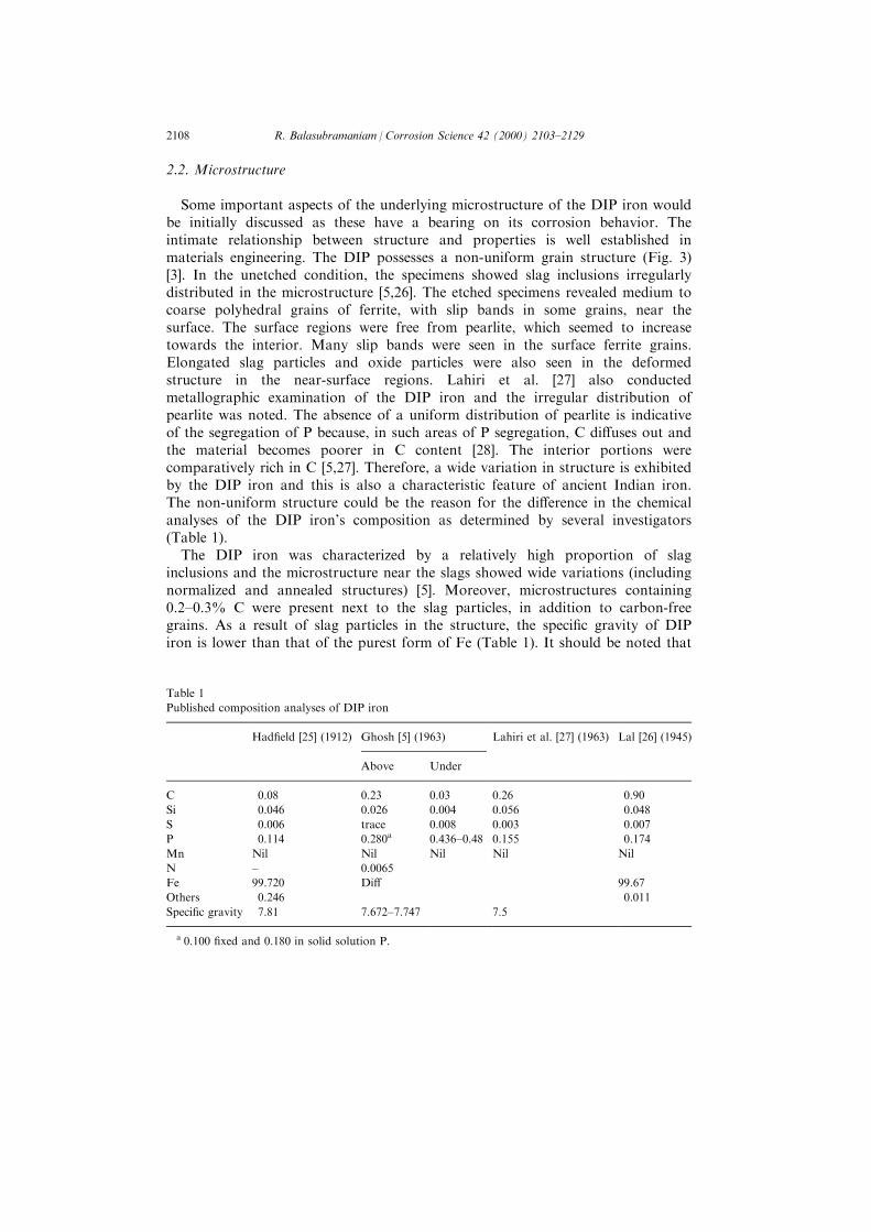
Some important aspects of the underlying microstructure of the DIP iron wouldbe initially discussed as these have a bearing on its corrosion behavior. Theintimate relationship between structure and properties is well established inmaterials engineering. The DIP possesses a non-uniform grain structure (Fig. 3)[3]. In the unetched condition, the specimens showed slag inclusions irregularlydistributed in the microstructure [5,26]. The etched specimens revealed medium tocoarse polyhedral grains of ferrite, with slip bands in some grains, near thesurface. The surface regions were free from pearlite, which seemed to increasetowards the interior. Many slip bands were seen in the surface ferrite grains.Elongated slag particles and oxide particles were also seen in the deformedstructure in the near-surface regions. Lahiri et al. [27] also conductedmetallographic examination of the DIP iron and the irregular distribution ofpearlite was noted. The absence of a uniform distribution of pearlite is indicativeof the segregation of P because, in such areas of P segregation, C di�uses out andthe material becomes poorer in C content [28]. The interior portions werecomparatively rich in C [5,27]. Therefore, a wide variation in structure is exhibitedby the DIP iron and this is also a characteristic feature of ancient Indian iron.The non-uniform structure could be the reason for the di�erence in the chemicalanalyses of the DIP iron's composition as determined by several investigators(Table 1).
The DIP iron was characterized by a relatively high proportion of slaginclusions and the microstructure near the slags showed wide variations (includingnormalized and annealed structures) [5]. Moreover, microstructures containing0.2±0.3% C were present next to the slag particles, in addition to carbon-freegrains. As a result of slag particles in the structure, the speci®c gravity of DIPiron is lower than that of the purest form of Fe (Table 1). It should be noted that
Table 1
Published composition analyses of DIP iron
Had®eld [25] (1912) Ghosh [5] (1963) Lahiri et al. [27] (1963) Lal [26] (1945)
Above Under
C 0.08 0.23 0.03 0.26 0.90
Si 0.046 0.026 0.004 0.056 0.048
S 0.006 trace 0.008 0.003 0.007
P 0.114 0.280a 0.436±0.48 0.155 0.174
Mn Nil Nil Nil Nil Nil
N ± 0.0065
Fe 99.720 Di� 99.67
Others 0.246 0.011
Speci®c gravity 7.81 7.672±7.747 7.5
a 0.100 ®xed and 0.180 in solid solution P.
R. Balasubramaniam / Corrosion Science 42 (2000) 2103±21292108

Fig. 3. (a) Entrapped slag inclusions in the iron of the Delhi pillar which appear as large black
particles, (b) structure at location A, and (c) at location B marked in (a). The magni®cation of (b) and
(c) are similar [3].
R. Balasubramaniam / Corrosion Science 42 (2000) 2103±2129 2109

the speci®c gravity is not uniform, which is also indicative of the non-uniformdistribution of the slag particles in the microstructure. The non-uniformdistribution of slag particles in the DIP iron can be clearly seen in themicrostructures provided by Ghosh [5], and Bardget and Stanners (Fig. 3) [3]. Theslag present in the DIP iron is generally microscopic in nature and only a few ofthem are present in larger sizes (Fig. 3). Slag results in the microstructure due tothe processing method employed to obtain iron. Iron was produced in ancientIndia by solid state reduction of high quality iron ore using charcoal [29,30]. Oncethe reduction was complete, the iron lumps produced were hammered in order toremove part of the liquid slag formed during the extraction process. Some of theslag invariably remained within the bulk of the material and this is the origin ofthe entrapped slag inclusions. Moreover, ancient Indian iron also shows thepresence of a small amount of unreduced iron oxides. Generally, silica wassprayed on the iron that was extracted and this combined with unreduced ironoxide, resulting in the slag fayelite, Fe2SiO4. Microstructural investigations on ironproduced during the Gupta period show that both slag and unreduced iron oxidewere present in the main body of Eran iron [20]. These unreduced iron oxides alsocontained carbon, presumably from the charcoal used for extraction [20]. Thepresence of carbon in these unreduced oxides would render these oxides cathodicin nature with respect to the surrounding matrix.
It must also be noticed that the slag particles in the DIP iron are in ®nemicroscopic form distributed unevenly in the microstructure. If the slag hadenclosed the individual iron lumps that were forge welded (in order to produce thelarge dimension of the pillar), it would have resulted in poor solid state fusion ofthe iron lumps. The pillar is a solid body [31] with good mechanical strength(yield strength YS of 23.5 tons/in.2, ultimate tensile strength UTS of 23.9 tons/in.2
and 5% elongation [5]). The relatively high strength, and the similarity of YS andUTS are indicative of the composite structure of the DIP iron. In fact, a cannonball ®red at the DIP in the 18th century (either by Nadir Shah in AD1739 orGhulam Quadir in AD1787) failed to break the pillar [23], which also suggeststhat slag does not coat the individual lumps that were forge welded [32].
A very interesting feature concerning the presence of slag particles in ancientIndian iron is that they are generally surrounded by a relatively higher fraction ofpearlite compared to regions far removed from the slags. This is observed in themicrostructures of DIP iron (see Fig. 3(c)) [3,4] and Eran iron [20,21]. Anothertypical example is seen in Fig. 4, which shows the microstructure of the Dharpillar iron. This pillar, which is about 900 years old, is nearly twice the length ofthe DIP, but lying presently in three broken pieces with a missing fourth pieceand a missing decorative capital [33±36]. Note that the pearlite volume fraction isrelatively higher near the slag particles. The presence of a large amount of pearlitenear the slag inclusions is indicative of P depletion in these regions. Chemicalanalysis of the P content in DIP iron has revealed that the majority of P contentin the DIP is in solid solution while a smaller amount occurs in the slags. In oneof the analysis, out of 0.28% P in the material, 0.10% P was in the ®xed state (i.e.in slags) with the rest being in solid solution in the metal [5]. The presence of P
R. Balasubramaniam / Corrosion Science 42 (2000) 2103±21292110

was also con®rmed, by electron microprobe analysis, in the entrapped slags of theEran iron and Dhar pillar iron. In the vicinity of slag inclusions, the regions aredepleted in P and these are the regions where C will concentrate [28]. This is thereason for the presence of a larger fraction of pearlite near the slag±metalinterfaces. The presence of pearlite near the slag inclusions has an importantimplication as regards understanding potential cathodic sites in ancient Indianiron (i.e. slag regions would act as cathodic reaction sites due to the large volumefraction of cementite present at these locations).
2.3. Origin of P in Metal
It will be shown later that the presence of P is crucial to the corrosionresistance of DIP. As the DIP iron contains a larger amount of P than modern-day iron (produced in blast furnaces), the reason for high P content in the iron isbrie¯y addressed. Interestingly, in nearly all published ancient Indian ironcompositions, a relatively larger percentage of P (compared to modern irons) canbe noted [5,26]. Modern steels cannot tolerate such high P contents as they would
Fig. 4. Microstructure of the Dhar pillar iron showing the presence of a larger fraction of pearlite near
slag particles. The slag has been analyzed in the electron microprobe analyzer and it is fayelite
(Fe2SiO4).
R. Balasubramaniam / Corrosion Science 42 (2000) 2103±2129 2111
be susceptible to cracking during the process of hot working due to the formationof liquid phosphides at the grain boundaries (the phenomenon being termed hotshotness). While it was earlier believed that P in ancient steels comes from slaginclusions [37], recent developments in slag chemistry help in understanding theprobable reason. The relatively higher P content in ancient iron is related to thekind of slag that was created in the extraction process by solid state reduction.Lime was not added in the ancient Indian furnaces, unlike in modern blastfurnaces, and therefore the slag generated in these ancient Indian furnaces wereessentially fayelitic slags (consisting of iron orthosilicates Fe2SiO4). This is alsocorroborated by available compositions of ancient Indian iron-making slags fromarchaeological excavation sites [26]. The slags do not contain lime [26]. Thetransfer of P from the metal into the slag is facilitated by the basic components(for example, FeO and CaO) in the slag. The e�ciency of removal of P frommetal is much higher for CaO compared to FeO in the slag. These facts are wellestablished in slag chemistry [38]. Therefore, the absence of CaO in the slags leadsto a lower e�ciency for removal of P from the metal, which invariably must haveresulted in higher P contents in ancient Indian irons. Thermodynamic analysis ofP removal from iron in the absence of CaO in the slag also provides the sameanswer. As the entrapped slag seen in the ancient Indian iron is generally fayeliticwithout any CaO, thermodynamics dictates that a higher amount of P shouldremain in solid solution in iron. This must be one of the reasons for the presenceof higher P in ancient Indian iron. It must also be noted that there are indicationsthat P addition was intentional. For example, Buchanan [39], in his detaileddescription of steel making in Karnataka in the 18th century, describes oneprimitive furnace operated at Devaraya Durga. In this furnace, conical claycrucibles were ®lled with a speci®c amount of wood from the barks of a plantCassia auriculata, and pieces of wrought iron, then sealed and ®red. Interestingly,the bark of this plant contains a high content of P, extracted by osmosis from theground [6,7].
3. Role of slag particles in the passivation process
The method of extraction of iron lumps used in constructing the DIP resultedin the presence of ®ne slag particles and unreduced ore in the microstructure ofthe iron. The presence of these second phase particles in the microstructure wouldresult in the creation of mini-galvanic corrosion cells when the iron is exposed tothe environment. The metal in the matrix (which is almost pure iron [2,4,5]) wouldact as the anode and the second phase particles (slag and unreduced iron oxides)as sites for cathodic reactions. This is reasonable as the unreduced iron oxidescontain carbon and the slag particles are surrounded by a large volume fraction ofcementite (see Fig. 4). Initially, the cathodic reactions that occur on these cathodicreduction sites provide the sink for the electrons liberated by the corrosion of themetal to its ions. The slag particles would therefore accelerate the corrosion of thematrix on exposure to the environment. Relatively high corrosion rates were
R. Balasubramaniam / Corrosion Science 42 (2000) 2103±21292112
observed experimentally in the initial exposure period of Eran iron compared tomild steel of similar C content [20]. Therefore, it is anticipated that the two-phasestructure of the DIP iron should corrode at a faster rate compared to iron ofsimilar composition, as the DIP iron is essentially a composite structure. Thecathodic nature of the second phase particles in DIP iron should also be relevantin the later stages of corrosion because, in atmospheric corrosion, the cathodicreduction of oxygen must be considered (as ferric oxyhydroxides are also goodelectronic conductors [40,41]) in addition to the reduction of some of thecorrosion products in the rust [42,43].
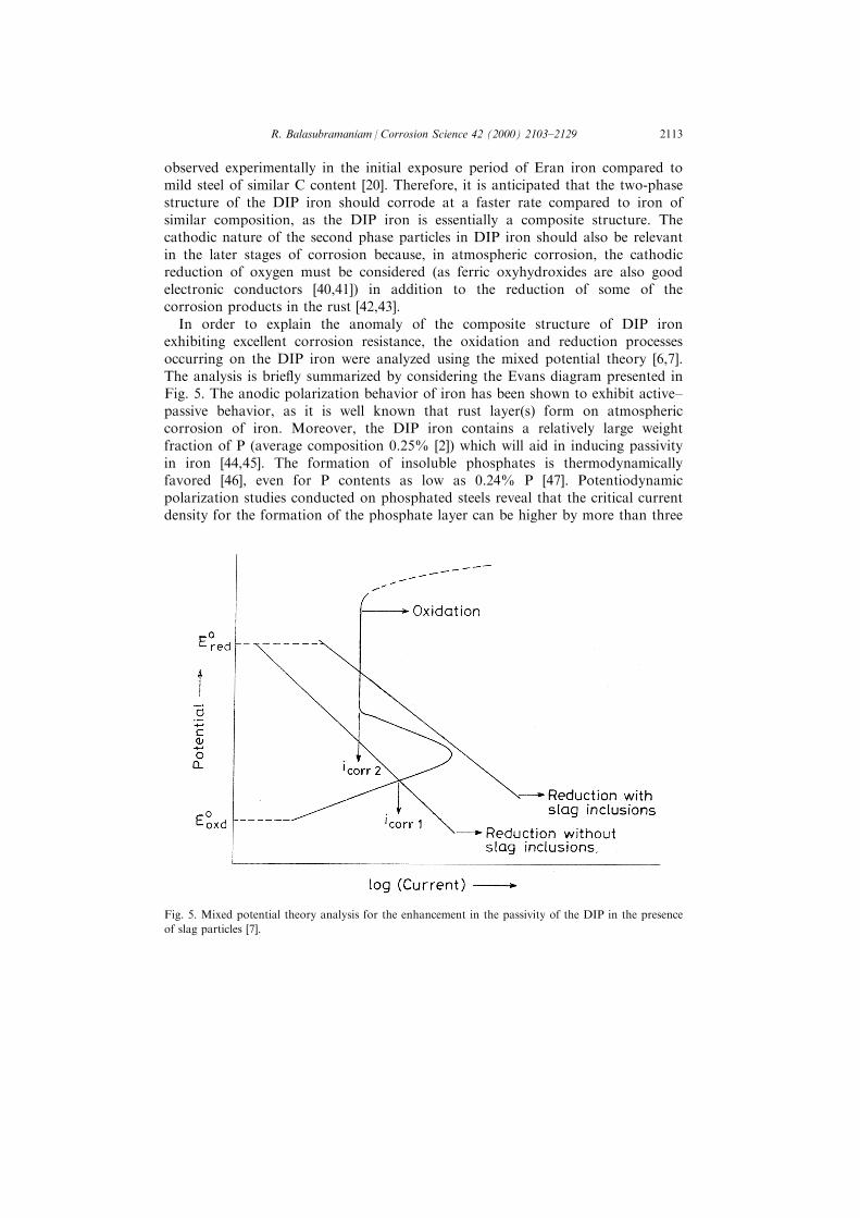
In order to explain the anomaly of the composite structure of DIP ironexhibiting excellent corrosion resistance, the oxidation and reduction processesoccurring on the DIP iron were analyzed using the mixed potential theory [6,7].The analysis is brie¯y summarized by considering the Evans diagram presented inFig. 5. The anodic polarization behavior of iron has been shown to exhibit active±passive behavior, as it is well known that rust layer(s) form on atmosphericcorrosion of iron. Moreover, the DIP iron contains a relatively large weightfraction of P (average composition 0.25% [2]) which will aid in inducing passivityin iron [44,45]. The formation of insoluble phosphates is thermodynamicallyfavored [46], even for P contents as low as 0.24% P [47]. Potentiodynamicpolarization studies conducted on phosphated steels reveal that the critical currentdensity for the formation of the phosphate layer can be higher by more than three
Fig. 5. Mixed potential theory analysis for the enhancement in the passivity of the DIP in the presence
of slag particles [7].
R. Balasubramaniam / Corrosion Science 42 (2000) 2103±2129 2113

orders of magnitude compared to that for steel without P [48]. Therefore, it isvalid to indicate that the DIP iron will exhibit active±passive behavior on anodicpolarization. It is important to stress that the exact nature of the passive ®lm neednot be known for this theoretical analysis, and only the formation of a passive®lm is required while considering the mixed potential analysis.
In case the DIP iron did not contain slag particles, the cathodic activationpolarization line would have intersected the anodic polarization curve in the activeregion. This is reasonable, as relatively large currents are needed to inducepassivity in iron containing P because the critical current density for passivation isvery high in iron containing P [48]. However, in the presence of slag particles, theexchange current of the cathodic reaction(s) would be higher than in the casewhen there were no slag particles and the cathodic activation polarization linewould shift to the right as shown in Fig. 5. Notice that current is depicted in theX-axis and not current density because this representation is useful in elucidatingthe e�ect of second-phase particles in inducing passivity on the DIP iron. Asimilar representation is also employed in Evans diagrams to understand areae�ects in galvanic corrosion using the mixed potential analysis [49]. Therefore, inthe presence of second phase particles, the higher current demand of the cathodicreaction(s) will demand a higher corrosion current. In this process, the criticalcurrent density for formation of the passive ®lm should be attained. Once this isachieved, the passive ®lm covers the surface and the corrosion rate is reduced tominimum. Therefore, the presence of slag particles may be indirectly bene®cial inthe case of the DIP iron as it helps in the induction of passivity on the surface.The above mixed potential analysis was experimentally validated bypotentiodynamic polarization studies using ancient Indian iron of di�erent slagcontents [6,7]. The above mixed potential theory analysis establishes that passivitycan also be induced on the DIP iron due to the presence of second phase particlesin the microstructure. The corrosion resistance of the DIP, therefore, hastheoretical support.
Although the above discussion clearly establishes that the second phase particlesin the DIP iron may be bene®cial in inducing passivity, it should be borne in mindthat alternate wetting and drying conditions are implied while consideringatmospheric corrosion. As shall be presented later, this is a very important factorin the formation of the protective ®lm at the metal±metaloxide interface. Wheniron, possessing similar second-phase particles (slags and oxides), is exposed to amore severe environment (for example, complete immersion in acidic or alkalinesolution), rapid localized attack occurs at the second-phase±matrix interfaces, andthe material corrodes at a much faster rate than normal mild steel. This has alsobeen experimentally validated for ancient Indian iron by constant immersioncorrosion testing and microstructural examination using a scanning electronmicroscope [20]. In the case of DIP iron, the importance of alternate wetting anddrying conditions for its corrosion resistance can be gleaned by analyzing theavailable corrosion rate data. Wranglen [2] utilized the data of Hudson [1] (whoobtained the same for mild steel exposed to Delhi's environment) to estimate thethickness of the protective ®lm that forms on the surface of the DIP. Assuming
R. Balasubramaniam / Corrosion Science 42 (2000) 2103±21292114
parabolic growth kinetics, he predicted the thickness of the scale to be 200 mmafter about 1600 years of growth [2]. The excellent match of the estimatedthickness with that experimentally estimated by Bardgett and Stanners [3], using apermanent-magnet type thickness gauge, is proof that the ®lm that forms on thesurface is protective in nature as it grows according to parabolic kinetics. It isinteresting at this juncture to note that the corrosion rates determined by constantimmersion testing of DIP iron samples in 0.001% NaCl and 0.003% SO2 solutionswere 6 mg/sq dm/day (mdd) and 54 mdd, respectively [5]. Utilizing these values, itcan be easily seen that had the pillar been completely immersed in an aqueoussolution, it would have been corroded much more severely.
The age of the pillar has been stated as 1600 years in the above discussion. Thepillar was constructed by Chandragupta II Vikramaditya (AD376±AD414), theChandra mentioned in the oldest Sanskrit inscription on the DIP and one of theimportant monarchs of the Gupta Empire. The identity of Chandra has recentlybeen analyzed based on numismatic, archaeological and literary evidence and ithas been conclusively proven that the iron pillar should be dated towards the endof Chandragupta II Vikramaditya's rule [11]. Assuming that the pillar wasconstructed in the ®rst quarter of the ®fth century AD, the pillar is at least 1600years old.
4. Rust analysis
Rust samples were characterized by XRD [22], FTIR [22], and MoÈ ssbauerspectroscopy [22]. The salient results of the characterization studies aresummarized. It must be again emphasized that the rust samples were obtainedfrom the region just below the decorative bell capital and therefore, this must bethe oldest undisturbed rust on the pillar as the area from where the rust wascollected is inaccessible to the public.
The signi®cant result of the XRD analysis of the DIP rust was the identi®cationof iron hydrogen phosphate hydrate in the crystalline form. The FTIR study ofthe DIP rust clearly established that, in addition to iron hydrogen phosphatehydrate, the scale also consisted of g-FeOOH (lepidocrocite), a-FeOOH (goethite),d-FeOOH (misawite), magnetite and phosphates [22]. (The amorphous phase d-FeOOH is termed misawite in this paper because of the pioneering studies ofMisawa and co-workers [44,45] proving its existence and importance in weatheringsteels). The hydrated nature of these products was also indicated. It was also seenin the XRD pattern that there was a very small amount of iron oxide/oxyhydroxides present in the crystalline form. The identi®cation of the oxide/oxyhydroxides of iron by FTIR clearly established that they are present in theamorphous form. The FTIR study also provided that phosphate ions were presentin the rust, con®rming the results of XRD. The MoÈ ssbauer spectroscopic study ofthe DIP rust samples proved conclusively that the oxyhydroxides and magnetitewere present in the amorphous form and also that iron in the phosphate was inthe +3 oxidation state. In summary, while XRD analysis proved the existence of
R. Balasubramaniam / Corrosion Science 42 (2000) 2103±2129 2115

crystalline iron hydrogen phosphate hydrate, FTIR and MoÈ ssbauer spectroscopyproved the presence of magnetite and several oxyhydroxides in the amorphousform.
In order to understand the presence of the identi®ed corrosion products in theDIP rust, the stabilities of these compounds were compared. The free energy offormation of the oxides and oxyhydroxides of iron, iron phosphate andphosphoric acid are provided in Table 2 [46]. Among the compounds listed in thetable, the phosphates are very stable based on their relatively large negative valuesof free energy of formation. This has also been veri®ed by noting that, in theternary Fe±P±O phase diagram, the formation of phosphate is favorable evenwhen only 0.24% P is present [47].
5. Process of protective rust formation
The process of protective ®lm formation on the exposed surface of the DIP canbe outlined based on the detailed characterization of DIP rust. It must beremembered that alternate wetting and drying conditions are implicit in thefollowing discussion on atmospheric corrosion.
Initially, the corrosion of the matrix is relatively fast due to the presence ofsecond phase particles in the microstructure. The usual corrosion products thatare observed in the case of mild steels (exposed to atmosphere containing nochloride ions) are generated. It is well known that the corrosion products thatform on iron on atmospheric exposure are a-FeOOH (goethite), g-FeOOH(lepidocrocite), Fe3ÿxO4 (magnetite) and X-ray amorphous matter [44,45,50]. Incase of exposure to marine environments (i.e. where chloride ions are present), theformation of b-FeOOH (akaganeite) is favored [51]. In the case of DIP iron, theformation of lepidocrocite and goethite was con®rmed by XRD analysis of 1.5-
Table 2
Free energy of formation of compounds at 298 K [46]
Compound formula Compound name DG (kJ/mol)
g-Fe2O3 Hematite ÿ742.4Fe0.95O WuÈ stite ÿ244.3FeO Stoichiometric ÿ251.4Fe3O4 Magnetite ÿ1014.2a-FeOOH Goethite ÿ490.4g-FeOOH Lepidocrocite ÿ471.4d-FeOOH Misawite ÿFePO4�2H2O Strongite ÿ1657.5H3PO4
Aqueous ÿ1142.6Crystalline ÿ1119.2Liquid ÿ1111.7
R. Balasubramaniam / Corrosion Science 42 (2000) 2103±21292116

year-old rust from the DIP surface by Lahiri et al. [27]. It is also likely that thesample analyzed by them could have contained amorphous d-FeOOH (misawite)as the formation of this phase during the initial corrosion of P-containing steelhas been conclusively proven by Misawa and co-workers [44,45] utilizing FTIR.This has also been independently con®rmed by other workers [52,53].
The initial enhanced corrosion of the matrix leads to the enrichment of Pconcentration at the metal±scale interface. In the presence of P at the interfacebetween the metal and rust, the formation of a compact layer of amorphous d-FeOOH layer next to the metal±metaloxide interface should be favored like thatobserved in the case of P-containing weathering steels [44,45]. Moreover,experiments have shown that H2PO4
ÿ ions prevent crystal growth of the corrosionproducts [44,45]. The formation of amorphous d-FeOOH confers the initialcorrosion resistance to the DIP iron. The d-FeOOH phase forms in adiscontinuous manner in normal mild steels whereas it forms a compact layer nextto the metal±metaloxide interface in the case of P- or Cu-containing weatheringsteels due to catalytic action [44,45]. The superior corrosion resistance of P- andCu-containing weathering steels has been attributed to this compact d-FeOOHlayer next to the metal surface, which is also enriched with the element(s) addedto provide weathering resistance (i.e. Cu and P). This mechanism may not applyto Cr-containing weathering steels [54]. While the a-FeOOH and g-FeOOH can beidenti®ed by X-ray di�raction, it is generally not possible to identify the d-FeOOHphase by this characterization technique [44,45].
It is important to note that the oxyhydroxides and magnetite present in the oldDIP rust are amorphous in nature and not crystalline. As it is known that theinitial oxide and oxyhydroxides that form on the DIP iron are crystalline innature [27], the long-term conversion of the crystalline forms of theseoxyhydroxides to the amorphous form is indicated. The crystalline oxide/oxyhydroxides of iron are converted to the amorphous state by the process ofalternate wetting and drying, as has been shown in P-containing weathering steel[44].
The enrichment of P in the d-FeOOH layer continues with prolonged exposureand this has been observed in P-containing weathering steels [44,45]. Thisenrichment should be responsible for the precipitation of the insoluble phosphateidenti®ed by XRD. The process of formation of crystalline iron hydrogenphosphate hydrate would be understood based on the literature available onphosphating of steels [55,56]. This exercise would also be useful in furtherunderstanding the reason for the DIPs excellent corrosion resistance.
Phosphating of iron is a commercially important coating method that involvesthe formation of relatively insoluble, electrically non-conducting thin ®lms ofmetal phosphates on the surface. It is known that the formation of a protectivephosphate layer on Fe surface involves the following four steps [55]. In the ®rststep, electrochemical attack of iron by orthophosphoric acid occurs over a widerange of concentration and temperature. In the case of DIP iron, the formation oforthophosphoric acid next to the metal surface has to be ®rst understood. Theenrichment of P at this location was earlier established due to the initial corrosion
R. Balasubramaniam / Corrosion Science 42 (2000) 2103±2129 2117

of matrix. Moreover, it is also important to note that the concentration of P isrelatively higher near the surface regions of the DIP iron than within the bulk[32]. It was earlier noted that the surface regions of DIP contain a high amount offerrite (depleted of carbon) which is due to the ®nal surface ®nishing operationprovided to the pillar during its manufacture [32]. It is known that P di�uses andconcentrates in regions where C is depleted [28] and therefore, concentration of Pis relatively higher near the surface regions of the pillar. Therefore, enrichment ofP in the d-FeOOH layer is expected.
This P enrichment has been experimentally determined by Ghosh [5] whomentioned that the P content in the DIP rust was 0.35% whereas the P content inthe DIP iron was 0.18%. The enrichment of P in the rust would initially result inthe formation of phosphoric acid at the metal±metaloxide interface due to thepresence of P at this location and also as free energy considerations favor itsformation. The moisture for phosphoric acid formation is obtained in thealternate wetting and drying cycles. In contact with phosphoric acid, thedissolution potential of iron becomes less noble and it causes the dissolution of Feto sparingly soluble dihydrogen phosphate according to
2H3PO4 � Fe4Fe�H2PO4�2�H2
The transient oxides of iron (in which Fe is in the +2 oxidation state) will alsobe corroded by phosphoric acid to provide Fe(H2PO4)2 according to
2H3PO4 � FeO4Fe�H2PO4�2�H2O
Among the above two reactions, mainly the ®rst one occurs [55].In the second stage, the contact of the metal shifts the equilibrium in such a
way that massive precipitation of monohydrogen phosphate FeHPO4 and tribasiciron phosphate Fe3(PO4)2 occurs. The precipitation reactions are
3Fe�H2PO4�24Fe3�PO4 �2�4H3PO4
Fe�H2PO4�24FeHPO4 � H3PO4
It is interesting to notice that iron is in the +2 oxidation state in thesephosphates. Both these phosphates are insoluble in nature. Moreover, thesephosphates are also amorphous in nature and this is well corroborated byexperimental evidence [55].
In normal phosphating processes, the phosphating reactions generally discussedare up to the sequence of events provided above. In normal practice, other cationssuch as Zn or Mn are also added to phosphoric acid. In some cases, oxidizingagents are added so that iron may appear in the coating as ferric phosphate [56].This is bene®cial to corrosion resistance because the crystal reorganization ofamorphous phosphates to ferric phosphates results in a large reduction in theporosity of the phosphate and subsequently, much improved protective properties[55].
R. Balasubramaniam / Corrosion Science 42 (2000) 2103±21292118

The oxidation of iron to ferric phosphate can also be achieved by alternatewetting and drying cycles [55]. The H2PO4
ÿ ions accelerate the air oxidation of Fe2+ to Fe 3+ under alternate wetting and drying cycles and prevents the crystalgrowth of the corrosion products [44,45,57±59]. Over time, Fe3(PO4)2 is oxidizedby atmospheric oxygen and H3PO4 to iron hydrogen phosphate hydrate accordingto
2Fe3�PO4�2�8H3PO4 � �3=2�O2 � 21H2O46�FePO4 � H3PO4 � 4H2O�In this compound, iron is in the +3 state and this can be understood if oneconsiders the above reaction in parts as follows:
2Fe3�PO4�2�2H3PO4 � �3=2�O2 � 9H2O46�FePO4 � 2H2O�
FePO4 � 2H2O� H3PO4 � 2H2O4FePO4 � H3PO4 � 4H2O
The dissolution and reprecipitation reaction also leads to a change in the pH ofthe metal±solution interface, which leads to a crystalline reorganization andfollowed, most importantly, by a large decrease in porosity. The crystallinereorganization is a very deep-seated reaction (at the metal±phosphate interface)because it modi®es the porosity of the passive layer and decreases markedly theexposed metallic surface [55]. Therefore, the formation of the crystallinemodi®cation of iron hydrogen phosphate hydrate from the amorphous phosphateis critical in providing excellent protection against further ingress of moisture andoxygen to the metal surface.
The continuous layer of crystalline iron hydrogen phosphate hydrate (formed atthe metal±metaloxide interface) is, therefore, responsible for the superior corrosionresistance of the DIP. Ghosh anticipated this mechanism in his excellent study ofthe DIP iron [5]. He stated that `P accumulates in a new phase at the base of themain oxide layer in the oxide form in combination with iron' and `so long as thenew phase at the base of the main oxide ®lm was not formed, the metal behaviourwas similar to that of the exposure surface of ordinary irons' [5]. Ghoshperformed some simple experiments with the DIP iron piece to assess the in¯uenceof P on rusting. The sample was polished and allowed to rust. When a thin andunequally distributed ®lm of rust was formed, it was photographed and thenslightly polished to remove the rust from the surface. This surface was treatedwith Stead's solution to observe the distribution of P on the surface. It was foundthat P was generally low in the areas where rust appeared more intensely.
It is important to also note that the crystalline modi®cation of iron hydrogenphosphate hydrate was obtained in the XRD analysis [22], thus indicating that thephosphate in the rust is relatively old. This validates the statement that theanalyzed DIP rust must be the oldest rust on the pillar as it was obtained from aregion inaccessible to the public (i.e. the region just below the decorative bellcapital).
Alternate wetting and drying conditions play an important role in the case ofatmospheric corrosion of the DIP because they accelerate the precipitation of
R. Balasubramaniam / Corrosion Science 42 (2000) 2103±2129 2119

protective crystalline phosphate and the amorphization of the DIP rust. Theamorphization of rust is also aided by the presence of H2PO4
ÿ ions [44,45]. Theiron pillar's weight is estimated to be approximately 6 tons and therefore, thelarge mass of the metal plays a contributory role in aiding the alternate wettingand drying processes. Sanyal and Preston [12] and, later, Bardgett and Stanners[3] proposed that the large mass of the pillar implies a large heat capacity andtherefore, the pillar will heat up or cool down faster than the surroundings. Thisprovides the right conditions of alternate wetting and drying of the iron pillarsurface. The intensity (i.e. rate) of wetting and subsequent drying would be muchmore in the case of DIP iron because of the large mass of the pillar.
In summary, the phosphate ®lm theory, originally presented by Ghosh [5] andelaborated in detail later [6,7], is valid. It is the crystalline iron hydrogenphosphate hydrate layer (and not amorphous as originally proposed [6,7]) at themetal±scale interface that is responsible for the excellent corrosion resistance ofthe DIP. The conclusion drawn is unambiguous as it has strong experimentalsupport from DIP rust characterization.
6. Rust cross section
The process of protective ®lm formation outlined above can also be understoodby analyzing the only published cross section microstructure of the DIP rust [5].The rust was obtained from the buried underground region when the pillar wasexcavated in 1961. The stone platform currently seen around the base of the pillarwas not present until the middle of the nineteenth century [60]. It was erected byBeglar [61] after he explored the underground regions of the courtyard area wherethe iron pillar is located. When the pillar was re-erected by Beglar, the stoneplatform was constructed and a coating of lead was provided on the buriedunderground surface of the pillar. This uneven coating of lead (of about 3 mm inthickness) was found to be in an excellent state of preservation when the buriedregion of the pillar was again excavated in 1961 on the eve of the centenary of theArchaeological Survey of India [26]. However, the buried portion was foundcovered with rust layers ranging from a few mm to 15 mm [5,26]. Interestingly,there were numerous cavities and corrosion pits were also observed on the surface.The composition of the rust in the buried underground was chemically analyzedand they were found similar to the rusts obtained above the ground [5]. The soilsamples in the nearby vicinity was found loaded with soluble sulfates andchlorides [26]. The iron in the buried regions is corroded more than the exposedsurface due to the galvanic action with the lead layer, as lead is cathodic withrespect to iron [23]. Simulation experiments conducted with lead-coated mild steelin soil environments [62] has clearly established the deleterious nature of the leadcoating as the corrosion is intense in areas where coating defects exist. Under suchcircumstances, it is anticipated that cross sectional analysis of the rust layer in theburied underground would provide a picture of the rust nature, but on anampli®ed scale. (A new lead coating was provided on the pillar in the buried
R. Balasubramaniam / Corrosion Science 42 (2000) 2103±21292120

underground region when it was relaid in a new foundation in the 1960s, muchagainst the wishes of the Chief Chemist of the Archaeological Survey of India[26]. Therefore, the iron in the buried underground region is currently subjected tointense galvanic corrosion. It is important to replace this lead coating withanother suitable coating for proper preservation of this important cultural andscienti®c object).
It is also to be noted that the surface ®lm that forms on the iron pillar in theburied underground region would be slightly di�erent from that which forms onthe exposed surface. This is due to the restricted nature of the buried soilenvironment. Under conditions of restricted oxygen supply, it is well establishedthat the major corrosion product on iron is magnetite [44]. Such a situationshould be obtained in the case of the DIP rust in the buried underground regions.Ghosh analyzed a sample of rust from the buried underground region and it wasseen that it was essentially magnetic in nature, based on the attraction of the rustto a magnet [5]. It is not possible to conclusively prove that the magnetic portionis entirely composed of magnetite as the other oxyhydroxides of iron are alsoparamagnetic [63] and therefore will also be attracted to a magnet. The magneticportion of the rust was analyzed by XRD and it was shown to consist ofmagnetite in addition to lepidocrocite and goethite [5]. Ghosh did not mention therelative amounts of these phases based on the XRD study as he was quoting theresults of the XRD work done at Bern. However, it can be reasonably predictedthat a higher amount of magnetite must have been present in the rust obtainedfrom the buried underground when compared to that obtained in the exposedregions. Apart from this the nature of the phosphate layer should be di�erent onthe exposed and buried surfaces of the DIP.
The rust from another ancient Indian iron clamp taken from the buriedconditions in a stone block were earlier analyzed and the results of its rustcharacterization provide valuable insights into the possible nature of the rust inthe buried underground regions of the DIP. This is important as both of theseirons were in a restricted environment. The Eran rust did not exhibit anycharacteristic di�raction lines as they were di�used in nature, which indicated thatthe corrosion products in the rust were in a ®ne state of aggregation. However,FTIR spectroscopy revealed the presence of a-FeOOH, g-FeOOH, d-FeOOH,magnetite and phosphates [21]. MoÈ ssbauer spectroscopy of the rust con®rmed theamorphous nature of the oxyhydroxides and indicated that magnetite was dopedwith some ions [21]. Scanning electron microscopy of the cross section of the rustindicated that it composed of a loose outer layer and an adherent inner layer [21].Compositional analysis using an electron probe microanalyzer indicated that theinner rust layer was enriched in P and the concentration of P was maximum at themetal±metaloxide interface [21]. It was concluded, based on the rust analysis, thatthe inner layer providing the protection was d-FeOOH in the amorphous formand this was enriched in P at the metal±metaloxide interface. Although thepresence of phosphates was indicated in the FTIR spectrum, they could not beidenti®ed by XRD and therefore, it is clear that the phosphate layer that waspresent must also have been amorphous in nature. Moreover, they must be
R. Balasubramaniam / Corrosion Science 42 (2000) 2103±2129 2121

present at the metal±metaloxide interface based on the compositional analysis ofthe rust. It was earlier seen that the phosphates that form on the surface of steelare generally amorphous in nature and the formation of crystalline phosphate(which incidentally is the most protective due to its low porosity content) takesplace either in the presence of oxidizers or due to a large number of wetting-and-drying cycles (i.e. by the process of dissolution and re-precipitation) [55].
Therefore, in addition to the phases identi®ed by Ghosh in the rust layers in theburied underground portion of DIP, the presence of amorphous phases like d-FeOOH and amorphous phosphates is likely. XRD analysis would not haverevealed these phases. Having established the general similarities in the rust thatforms above and below the ground on the DIP, it is illuminating to view thepublished microstructure of the rust formed in the underground buried regions ofthe DIP [5]. It is reproduced in Fig. 6. It is clearly noticed that the rust iscomposed of three distinct layers, with the outer layer (marked A) being opticallyactive while the inner two layers (marked B and C) being optically dull. The innermost layer (marked C) is present as a thin layer next to the metal±metaloxideinterface. The layered structure of the protective rust in weathering steel is wellestablished [44,45,54]. Regarding the optical nature of the layers on weathering
Fig. 6. Cross section of DIP rust in the buried underground [5]. Note the presence of three distinct
layers in the rust with the inner two layers being optically dull indicating their amorphous nature.
R. Balasubramaniam / Corrosion Science 42 (2000) 2103±21292122
steels, Okada et al. [64,65] pointed out that the inner optically isotropic layer ofthe surface rust is composed of X-ray amorphous spinel type iron oxide which canprotect the steel matrix. Yamashita et al. [54] also observed, by microscopicobservation using re¯ected polarized light and crossed nicols, that the rust layerpresent on a weathering steel exposed for 26 years could be divided into twoparts: an outer layer which was optically active (i.e. illuminated) and an innerlayer which was optically isotropic (darkened). On the other hand, the surface rustformed on mild steels was of the mottled structure consisting of the opticallyactive and isotropic corrosion products [54]. It is also established that weatheringsteels obtain their protection due to the presence of the amorphous (dark) innerlayer [54]. Therefore, based on the above studies, it is reasonable to state that theinner two layers seen in the underground DIP rust microstructure of Fig. 6 areamorphous in nature while the outer layer is crystalline in nature. The innermostthin layer seen next to the metal surface must be due to the precipitation ofphosphates (most likely in the amorphous form as the rust did not undergodrastic alternate wetting and drying) because of the enrichment of P at thislocation. The optically dull layer appearing next (B) should correspond to d-FeOOH. Of course, the major di�erence between the rust seen in the buriedunderground and above-the-ground portions is that there should be a loweramount of crystalline oxide/oxyhydroxides in above-ground rust due to alternatewetting and drying cycles. Moreover, the phosphate layer would be in thecrystalline form in the above-the-ground dust on prolonged wetting-and-dryingcycling. This is also corroborated by the characterization of DIP rust [22].Therefore, Fig. 6 literally provides the visual picture for the nature of protectivepassive ®lm that forms on the DIP. In the rust exposed to the atmosphere, theoutermost two layers (A and B) would be optically dull, while the two innermostlayers (C) would be optically bright.
7. Color of rust
The color of rust on a freshly cut surface of the pillar exposed to theenvironment was studied by Ghosh [5]. He stated that in one year's time, after thesurface was freshly cut, some brown oxide could be removed by rubbing but anadherent thin layer of rust was formed, though very thin and unequallydistributed. The oxyhydroxides of iron are brownish in color while magnetite isblack in color [54]. After 14 months, a thin ®lm was formed but again it was notuniformly distributed. After another 6 months (i.e. for a total of 20 months), thecolor of the ®lm was almost the color of the main surface and the ®lm was stillthin and non-uniformly distributed. The rust was still bright at some places andrusting pits were also found, some of which could be removed by rubbing. At thispoint, the surface was rubbed with emery paper to remove the rust and this cameo� under slight rubbing though the pits remained. After another 15 months of thisrubbing exercise, the surface was observed. The pits had smoothed out exceptingone or two but the location was still bright and had not taken the color of the
R. Balasubramaniam / Corrosion Science 42 (2000) 2103±2129 2123
surface nearby. The above studies clearly indicate that the formation of theprotective ®lm on the freshly cut surface takes time.
Ideas about the ®lm formation can be obtained from the color of the growingrust on the DIP. The ASI has constructed an iron grill cage surrounding the DIPin 1997 to prevent visitors from damaging the pillar. The surface of the`metallurgically' polished bright surface, occurring at a height of about 5 feet fromthe ground, (when the pillar was in intimate human contact) was photographed atperiodic intervals to obtain insights on the rust formation. The presence of arectangular metal insert [32] at this location provided the reference frame. Afterabout a year of the cage construction, the previously bright area was covered witha thin dark-brown layer which was adherent on the surface. In the location of theforge welded joints, the rust was black in color indicative of magnetite formationin these areas of enhanced corrosion caused by the presence of the interface.Interestingly, there were some regions above the polished region which were brightyellow in color. These observations are in conformity with that of Ghosh on theinitial rust formation on the DIP. The results of Lahiri et al. [27] further indicatethat the rust must be composed of g-FeOOH, a-FeOOH and magnetite inaddition to X-ray amorphous matter, as discussed earlier. Observations in early2000 indicated that the rust layer was black in color. In some regions of thepreviously-bright surface, the color approached that of the undisturbed.
It is also interesting to note the color of the stable protective ®lm that forms onthe pillar after a long exposure to the environment. Some early observers of thepillar have stated that the pillar possessed a golden hue [6,7,17]. When the DIP isviewed normally, it appears black in color with good re¯ectivity [13], indicatingthat the passive layer is relatively thin. However, when the DIP surface (especiallythe region inaccessible to the public, i.e. above the oldest Sanskrit inscriptions) isviewed at an acute angle in bright sunlight, the color of rust is yellowish-red innature and it provides the visual e�ect of a golden hue. Interestingly, yellowspecks can be seen distributed all over the rust layer and this is the crystallinephosphate. Therefore, the golden hue of the pillar is related to the nature of theprotective passive ®lm that forms on its surface.
8. Comparison of corrosion of DIP iron with weathering steels
The protective passive ®lm that form on the DIP would be contrasted with the®lms forming on mild and weathering steels on atmospheric exposure. Structure-related issues of the rusts are discussed as the compositional factors have alreadybeen outlined earlier.
The rusting of normal mild steel and weathering steel is ®rst addressed. Wheniron is exposed to the environment, the ®rst oxides that form are theoxyhydroxides of Fe which are oxidized from Fe(II) complexes [44]. Althoughseveral di�erent allotropic modi®cations of the oxyhydroxides have been proposedto form on the surface of iron on initial exposure to the environment, there are®rm evidences in the literature to suggest and prove that the ®rst oxyhydroxide to
R. Balasubramaniam / Corrosion Science 42 (2000) 2103±21292124
form is g-FeOOH [44]. After this forms, a part of it begins to transform toanother allotropic modi®cation (a-FeOOH) and the rust at later times iscomposed of both these oxyhydroxides. Both these oxyhydroxides are notprotective against corrosion and they readily crack allowing for ingress of oxygenand moisture to reach the metal surface and cause further corrosion. However,with time, a part of the FeOOH formed transforms to magnetic oxides of iron,which are much more protective than these oxyhydroxides [44]. There is alsodebate on the exact nature of the magnetic oxide that form on exposure of theiron to the environment. This is because the di�raction peaks of Fe3O4 and g-Fe2O3 occur at the same location. However, MoÈ ssbauer studies of rust formed onsteel exposed to the environment does indicate that Fe3O4 (more precisely calledFe3ÿ xO4) forms ®rst and this is later converted to g-Fe2O3 [21]. The formation ofthis magnetic oxide results in protection and the oxidation (corrosion) ratesdecrease once these oxides form on the surface from the oxyhydroxides. Inaddition to a- and g-FeOOH, there can be another oxyhydroxide of nature d-FeOOH which can form on atmospheric exposure of iron. It is interesting to notethat d-FeOOH is generally amorphous in nature and therefore no di�ractionpeaks would be observed from this phase [44]. In ordinary mild steels, this phasedoes not develop as a continuous layer but rather in a discontinuous manner(Fig. 7) as it results from the dehydration±oxidation of the Fe(II) complexes [44].Therefore, the d-FeOOH that forms on ordinary mild steels is not protective innature. However, it is possible for this d-FeOOH to form, next to the metalsurface, a continuous layer such that the steel obtains corrosion resistance (Fig. 7),as the oxyhydroxide is also amorphous in nature. The formation of d-FeOOH asa continuous layer next to the metal surface is catalyzed by the presence of P andCu in the material [44]. Moreover, the d-FeOOH is enriched with P and Cu,elements that are added for improving atmospheric corrosion [44]. The presence ofthis amorphous layer is the reason for the excellent corrosion resistance of theweathering steels [44,45] although the time required for forming the protectivelayer is determined by the exposure conditions. Several schemes for the formationof rust on steels as a function of pH and environmental factors are available [44].
In the case of DIP, the process of protective rust formation has been outlined indetail earlier. The structure of the passive ®lm on the DIP is also provided,schematically, in Fig. 7 for comparison with the ®lms that form on mild andweathering steels. Cross sectional microstructural analysis of DIP rust (see Fig. 6)con®rms the structure of DIP rust presented.
9. Conclusions
The nature of the protective passive layer on the corrosion resistant DIP hasbeen addressed based on a detailed characterization of its rust. The rust iscomposed of iron hydrogen phosphate hydrate (FePO4�H3PO4�4H2O) in thecrystalline form in addition to a-, g-, d-FeOOH and magnetite, all in amorphousform. The process of protective rust formation on DIP iron is outlined based on
R. Balasubramaniam / Corrosion Science 42 (2000) 2103±2129 2125
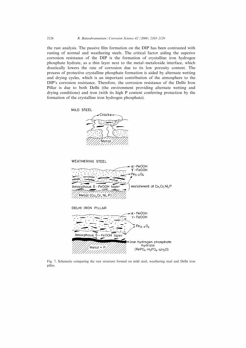
the rust analysis. The passive ®lm formation on the DIP has been contrasted withrusting of normal and weathering steels. The critical factor aiding the superiorcorrosion resistance of the DIP is the formation of crystalline iron hydrogenphosphate hydrate, as a thin layer next to the metal±metaloxide interface, whichdrastically lowers the rate of corrosion due to its low porosity content. Theprocess of protective crystalline phosphate formation is aided by alternate wettingand drying cycles, which is an important contribution of the atmosphere to theDIP's corrosion resistance. Therefore, the corrosion resistance of the Delhi IronPillar is due to both Delhi (the environment providing alternate wetting anddrying conditions) and iron (with its high P content conferring protection by theformation of the crystalline iron hydrogen phosphate).
Fig. 7. Schematic comparing the rust structure formed on mild steel, weathering steel and Delhi iron
pillar.
R. Balasubramaniam / Corrosion Science 42 (2000) 2103±21292126

Acknowledgements
The author gratefully acknowledges the co-operation of the ArchaeologicalSurvey of India.
References
[1] J.C. Hudson, The Delhi iron pillar, Nature 172 (1953) 499±500.
[2] G. Wranglen, The rustless iron pillar at Delhi, Corrosion Science 10 (1970) 761±770.
[3] W.E. Bardgett, J.F. Stanners, The Delhi iron pillar Ð a study of the corrosion aspects, J. Iron
and Steel Inst. 210 (1963) 3±10, NML Technical J. 5 (1963) 24±30.
[4] R. Had®eld, Discussion on Friend and Thorneycraft's paper on ancient iron, J. Iron and Steel
Inst. 112 (1925) 233±235.
[5] M.K. Ghosh, The Delhi iron pillar and its iron, NML Technical J. 5 (1963) 31±45.
[6] R. Balasubramaniam, Studies on the corrosion resistance of the Delhi iron pillar, NML Technical
J. 37 (1995) 123±145.
[7] R. Balasubramaniam, Mixed potential theory analysis of the corrosion resistance of the Delhi
iron pillar, Trans. Indian Inst. Metals 50 (1997) 23±35.
[8] W.H.J. Vernon, First experimental report to the atmospheric corrosion research committee of the
British non-ferrous metals research association, Trans Farad. Soc. 19 (1923-24) 839±934.
[9] W.H.J. Vernon, Second experimental report to the atmospheric corrosion research committee of
the British non-ferrous metals research association, Trans. Farad. Soc. 23 (1927) 113±204.
[10] W.H.J. Vernon, A laboratory study of the atmospheric corrosion of metals, Trans. Farad. Soc.
31 (1935) 1668±1700.
[11] R. Balasubramaniam, Identity of Chandra and Vishnupadagiri of the Delhi iron pillar inscription:
numismatic, archaeological and literary evidence, Bull. Metals Museum 34 (2000) 42±64.
[12] B. Sanyal, R. Preston, Note on Delhi Pillar, Chemical Research Laboratory, London, 1952.
[13] U.R. Evans, in: The Corrosion and Oxidation of Metals, Edward Arnold, London, 1968, pp.
191±192 (First Supplementary Volume).
[14] W. Rosenhain, Discussion on Whyte's paper on note on the corrosion of iron and steel, Trans.
Farad. Soc. 11 (1916) 236±243.
[15] W. Rosenhain, in: Physical Metallurgy, Constable, London, 1915, pp. 329±330.
[16] A. Herrero, M. de Zubiria, The phenomenon of corrosion of iron and steel, J. Iron and Steel
Inst. 118 (1928) 109±125.
[17] H.G. Graves, Further notes on the early use of iron in India, J. Iron and Steel Inst. 85 (1912)
187±202.
[18] T.R. Anantharaman, The iron pillar at Kodachadri in Karnataka, Current Science 76 (1999)
1428±1430.
[19] T.R. Anantharaman, The Rustless Wonder Ð A Study of the Delhi Iron Pillar, Vigyan Prasar,
New Delhi, 1997.
[20] V. Puri, R. Balasubramaniam, A.V. Ramesh Kumar, Corrosion behaviour of ancient 1500-year
old Gupta iron, Bull. Metals Museum 28-II (1997) 1±10.
[21] A.V. Ramesh Kumar, R. Balasubramaniam, Corrosion product analysis of ancient corrosion
resistant Indian iron, Corrosion Science 40 (1998) 1169±1178.
[22] R. Balasubramaniam, A.V. Ramesh Kumar, Characterization of Delhi iron pillar rust by X-ray
di�raction, Fourier transform infrared spectroscopy, and MoÈ ssbauer spectroscopy, Corrosion
Science, 42 (2000) 2085±2101.
[23] R. Balasubramaniam, On the presence of lead in the Delhi iron pillar, Bull. Metals Museum 29-I
(1998) 19±39.
[24] R. Balasubramaniam, The decorative bell capital of the Delhi iron pillar, JOM 50 (3) (1998) 40±
47.
R. Balasubramaniam / Corrosion Science 42 (2000) 2103±2129 2127

[25] R. Had®eld, Sinhalese iron and steel of ancient origin, J. Iron Steel Inst. 85 (1912) 134±174.
[26] B.B. Lal, in: M.C. Joshi, S.K. Gupta, Shankar Goyal (Eds.), The Delhi Iron Pillar: Its Art,
Metallurgy and Inscriptions, Kusumanjali Publications, Jodhpur, 1996, pp. 22±58.
[27] A.K. Lahiri, T. Banerjee, B.R. Nijhawan, Some observations on corrosion resistance of ancient
Delhi iron pillar and present-time adivasi iron made by primitive methods, NML Tech. J. 5
(1963) 46±54.
[28] A. Bramley, F.W. Haywood, A.T. Coopers, J.T. Watts, The di�usion of non-metallic elements in
iron and steel, Trans. Farad. Soc. 31 (1935) 707±734.
[29] B. Prakash, Metallurgy of iron and steel making and blacksmithy in ancient India, Ind. J. Hist.
Sci. 261 (1991) 351±371.
[30] B. Prakash, V. Tripathi, Iron technology in ancient India, Metals and Materials 2 (1986) 568±
579.
[31] V.N. Bindal, A. Kumar, J.N. Som, S. Chandra, Y. Kumar, J. Lal, Ultrasonic NDT Study on the
Historical Delhi Iron Pillar, in: Proc. Conf. Ultrasonic International 89, Butterworth Scienti®c,
England, 1989, pp. 95±100.
[32] R. Balasubramaniam, Elucidation of manufacturing methodology employed to construct the main
body of the Delhi iron pillar, Bull. Metals Museum 31 (1999) 40±63.
[33] V.A. Smith, The iron pillar of Dhar, J. Roy. Asiatic Soc. G. Brit. and Ireland (1898), 143±145.
[34] H. Cousens, The iron pillar at Dhar, Ann. Rep. Arch. Sur. Ind. (1902/03) 205±212.
[35] B. Prakash, Archaeometallurgical study of iron pillar at Dhar, Puratattva 20 (1989) 111±122.
[36] K. Roessler, The non rusting iron pillar at Dhar, NML Tech. J. 37 (1995) 143±154.
[37] U.R. Evans, in: Corrosion of Metals, Edward Arnold, London, 1926, p. 266.
[38] J.J. Moore, Slag chemistry, in: Chemical Metallurgy, 2nd ed., Butterworth±Heinemann, Oxford,
1990, pp. 152±192 (Chapter 5).
[39] F.A. Buchanan, Journey from Madras Through the Countries of Mysore, Canara and Malabar,
East India Company, London, 1807.
[40] M. Cohen, K. Hashimoto, Cathodic reduction of g-FeOOH, g-Fe2O3 and oxide ®lms on iron, J.
Electrochem. Soc. 121 (1974) 427±432.
[41] J. Keiser, C. Brown, R.H. Heidersbach, The electrochemical reduction of rust ®lms on weathering
steel surfaces, J. Electrochem. Soc. 129 (1982) 2686±2689.
[42] U.R. Evans, Mechanism of rusting, Corrosion Science 9 (1969) 813±821.
[43] U.R. Evans, C.A.J. Taylor, Mechanism of atmospheric rusting, Corrosion Science 12 (1972) 227±
246.
[44] T. Misawa, T. Kyuno, W. Suetaka, S. Shimodaira, The mechanism of atmospheric rusting and
the e�ect of Cu and P on the rust formation of low alloy steels, Corrosion Science 11 (1971) 35±
48.
[45] T. Misawa, K. Asami, K. Hashimoto, S. Shimodaira, The mechanism of atmospheric rusting and
the protective rust on low alloy steel, Corrosion Science 14 (1971) 279±289.
[46] T.L. Wood, R.M. Garrels, in: Thermodynamic Values at Low Temperature for Natural Inorganic
Materials: A Critical Summary, Oxford University Press, Oxford, 1987, pp. 100±106.
[47] V.A. Urasova, N.P. Levenets, A.M. Samarin, Non metallic inclusions in the Fe±P±O system,
Izvest. Akad. Nauk SSSR, Metally 6 (1966) 24±30.
[48] R.L. Chance, W.D. France Jr, Anodic polarization characteristics of phosphated steels, Corrosion
25 (1969) 329±335.
[49] M.G. Fontana, N.D. Greene, in: Corrosion Engineering, 2nd ed., McGraw-Hill, New Delhi,
1978, pp. 330±335.
[50] I. Suzuki, Y. Kisamatsu, N. Masuko, Nature of atmospheric rust on iron, J. Electrochem. Soc.
127 (1980) 2210±2215.
[51] P. Keller, Occurrence, formation and phase transformation of beta FeOOH in rust, Werksto�e
und Korrosion 20 (1969) 102±108.
[52] H. Kihira, S. Ito, T. Murata, The behaviour of phosphorous during passivation of weathering
steel by protective patina formation, Corrosion Science 31 (1990) 383±388.
[53] J.T. Keiser, C.W. Brown, Characterization of the passive ®lm formed on weathering steel,
Corrosion Science 23 (1983) 251±259.
R. Balasubramaniam / Corrosion Science 42 (2000) 2103±21292128
[54] M. Yamashita, H. Miyuki, Y. Matsuda, H. Nagano, T. Misawa, The long term growth of the
protective rust layer formed on weathering steel by atmospheric corrosion during a quarter of a
century, Corrosion Science 36 (1994) 283±299.
[55] E.L. Ghali, R.J.A. Potoin, The mechanism of phosphating of steel, Corrosion Science 12 (1972)
583±594.
[56] D.E.C. Carbridge, in: Phosphorus: An Outline of its Chemistry, Biochemistry and Uses, 5th ed.,
Elsevier, Amsterdam, 1995, pp. 520±521.
[57] M. Cher, N. Davidson, The kinetics of the oxygenation of ferrous iron in phosphoric acid
solution, J. Am. Chem. Soc. 77 (1955) 793±798.
[58] J. King, W. Davidson, Kinetics of the ferrous iron±oxygen reaction in acidic phosphate±
pyrophosphate solutions, J. Am. Chem. Soc. 80 (1958) 1542±1549.
[59] W. Stumm, G.F. Lee, Oxygenation of ferrous iron, Ind. Engg. Chem. 53 (1961) 143±146.
[60] R. Balasubramaniam, New insights on the corrosion of the Delhi iron pillar based on historical
and dimensional analysis, Current Science 73 (1987) 1057±1067.
[61] Y.D. Beglar, Archaeological Survey of India Annual Reports IV (1871/72) 28±30.
[62] R. Balasubramaniam, Some aspects of lead presence in the Delhi iron pillar, Current Science 77
(1999) 681±686.
[63] A.K. Singh, R. Ericsson, L. Haggstrom, J. Bullman, MoÈ ssbauer and X-ray di�raction phase
analysis of rusts from atmospheric test sites with di�erent environments in Sweden, Corrosion
Science 25 (1985) 931±945.
[64] H. Okada, Atmospheric corrosion of steels, J. Soc. Mater. Sci. Japan 17 (1968) 705±7709.
[65] H. Okada, Y. Hosoi, K. Yukawa, H. Naito, Structure of the rust formed on low alloy steels in
atmospheric corrosion, J. Iron Steel Inst. Japan 55 (1969) 355±365.
R. Balasubramaniam / Corrosion Science 42 (2000) 2103±2129 2129