on some classes of sequential spiking neural p systems
TRANSCRIPT

1
On Some Classes of Sequential Spiking Neural P
Systems
Xingyi Zhang
Key Lab of Intelligent Computing and Signal Processing of Ministry of Education,
School of Computer Science and Technology, Anhui University, Hefei 230039, China
Xiangxiang Zeng
Department of Computer Science, Xiamen University, Xiamen361005, China
Bin Luo
Key Lab of Intelligent Computing and Signal Processing of Ministry of Education,
School of Computer Science and Technology, Anhui University, Hefei 230039, China
Linqiang Pan (Corresponding author)
Key Laboratory of Image Processing and Intelligent Control, School of Automation,
Huazhong University of Science and Technology, Wuhan 430074, China

Abstract
Spiking neural P systems (SN P systems, for short) are a classof distributed paral-
lel computing devices inspired by the way neurons communicate by means of spikes,
where neurons work in parallel in the sense that each neuron that can fire should fire,
but the work in each neuron is sequential in the sense that at most one rule can be ap-
plied at each computation step. In this work, with biological inspiration, we consider
SN P systems with the restriction that at each step one of neurons (i.e., sequential mode)
or all neurons (i.e., pseudo-sequential mode) with the maximum (or, dually, minimum)
number of spikes among the neurons that are active (can spike) will fire; if an active
neuron has more than one enabled rules, then it non-deterministically chooses one of
enabled rules to be applied, and the chosen rule is applied inan exhaustive manner (a
kind of local parallelism): the rule is used as many times as possible. This strategy
makes the system sequential or pseudo-sequential from the global view of the whole
network and locally parallel at the level of neurons; and we obtain four types of SN P
systems: maximum/minimum spike number induced sequential/pseudo-sequential SN
P systems with exhaustive use of rules. We prove that SN P systems of these four types
are all Turing universal as number generating computation devices. These results illus-
trate that the restriction of sequentiality may have littleeffect on the computation power
of SN P systems.
2

1 Introduction
The (human) brain is a complex and enormous information processing system, where
more than a trillion neurons working in a cooperative mannerare able to perform tasks
that are not yet matched by the tools we can build with our current technology, e.g.,
thought, self-awareness, intuition. Actually, biology isa rich source of inspiration for
informatics as natural computing proves; particularly, the brain is the “gold mine” of
this intellectual enterprise. We believe that if somethingreally great is to appear in
informatics in the near future, then this “something” will be suggested by the brain, just
as shown by the Turing machine and the finite automaton (Paunet al., 2009).Spiking
neural P systems(SN P systems, for short) are a class of distributed parallelcomputation
devices introduced in (Ionescu et al., 2006), as an attempt to learn “something” from
the brain. We would like to stress here that SN P systems are not meant to provide the
answer to the learning-from-brain challenge, but at least away to call once again the
attention to this challenge.
SN P systems are inspired by the way neurons communicate by means of spikes
(electrical impulses of identical shape). Such systems provide a novel viewpoint to in-
vestigate spiking neural networks in the framework of an emergent research area, called
membrane computing. Membrane computing is one of the recent branches ofnatural
computing, which was initiated by G. Paun in 1998 (Paun, 2000) and hasdeveloped
rapidly (already in 2003, Information Sciences Institute considered membrane comput-
ing asa “fast emerging research area in computer science”, see http://esi-topics.com).
The aim is to abstract computing ideas (data structures, operations with data, ways
to control operations, computing models, etc.) from the structure and the function-
3

ing of a single cell and from complexes of cells, such as tissues and organs including
the brain. The models obtained are called P systems, and thiswas proved to be a
rich framework for handling many problems related to computing (Ishdorj et al., 2010;
Wang et al., 2010; Xu et al., 2013). We refer the reader to (Paun, 2002) and (Paun
et al., 2010) for the general information about membrane computing, and to the website
(http://ppage.psystems.eu) for the up-to-date information.
Briefly, an SN P system consists of a set ofneuronsplaced in the nodes of a directed
graph. Each neuron contains a number of copies of a single object type called aspike,
which is denoted by the symbola in what follows. The communications between neu-
rons are achieved by sending signals (in the form of spikes) alongsynapses(arcs of the
graph). The spikes evolve by means ofextended spiking rules, which are of the form
E/ac → ap; d, whereE is a regular expression over{a} andc, p, d are natural numbers,
c ≥ 1, p ≥ 1, d ≥ 0, with the restriction ofc ≥ p. The spikes can also be removed from
the neurons byextended forgetting rulesof the formE/ac → λ. If a neuron containing
k spikes such thatak ∈ L(E), k ≥ c, then the rules with the regular expressionE are
enabled. It is possible that there are more than one rule thatare enabled in a neuron
at some moment, since two firing rules,E1/ac1 → ap1 ; d1 andE2/a
c2 → ap2; d2, may
haveL(E1) ∩ L(E2) 6= ∅. In this case, the neuron will non-deterministically choose
one of the enabled rules to use. If the ruleE/ac → ap; d is applied in a neuron, thenc
spikes are consumed from the neuron, andp spikes are produced after a delay ofd steps.
These spikes are sent to all neurons connected by an outgoingsynapse from the neuron
where the rule was applied. The use of the ruleE/ac → λ will removec spikes from
the neuron. All neurons work in parallel in the sense that at each step each neuron that
4

can apply a rule should do it, while the rules in each neuron are applied in a sequential
manner with the meaning that at most one rule is applied in each neuron. One of the
neurons is designated as theoutput neuronof the system, and its spikes are also sent
to the environment. Various ways can be used to define the result of a computation.
In this work, we use as the computation result the total number of spikes sent to the
environment by the output neuron.
Many computational properties of SN P systems have been studied. SN P systems
were proved to be computationally complete (equivalent with Turing machines or other
equivalent computing devices; we also say that SN P systems are universal) as number
computing devices (Ionescu et al., 2006; Pan et al., 2011, 2012), language generators
(Chen et al., 2007, 2008), and function computing devices (Paun et al., 2007). SN
P systems were also used to (theoretically) solve computationally hard problems in a
feasible amount of time (see, e.g., (Ishdorj et al., 2010; Wang et al., 2010)).
At the level of neurons, a kind of local parallelism, calledexhaustive use of rules,
was proposed in (Ionescu et al., 2007), where in each neuron an applicable rule is used
as many times as possible. The biological motivation of exhaustive use of rules is that
an enabled chemical reaction consumes related substances as much as possible. It was
proved that SN P systems with exhaustive use of rules are universal if the neurons work
in parallel (Ionescu et al., 2007; Zhang et al., 2008).
Although biological neurons in the brain work in parallel, they are not synchronized
by a universal clock as assumed in SN P systems. Several authors have noticed that
the maximally parallel way of neuron working is rather non-realistic and considered
various “strategies” of neuron working, e.g., (Cavaliere et al., 2009), (Freund, 2005),
5

(Ibarra et al., 2006) and (Zhang et al., 2012). In (Ibarra et al., 2009), SN P systems
were considered to function in a sequential manner induced by maximum (or, dually,
minimum) spike number, i.e., if at any computation step there is more than one ac-
tive neuron, then only the neuron(s) containing the maximum(or minimum) number
of spikes (among the currently active neurons) will be able to fire. If there is a tie for
the maximum number of spikes stored in active neurons, then two distinct strategies
can be considered:max-pseudo-sequentiality(all the active neurons with the maximum
number of spikes will fire) andmax-sequentiality(only one of the active neurons with
the maximum number of spikes will fire). Similarly, we havemin-pseudo-sequentiality
andmin-sequentialityfor the case that there is a tie for the minimum number of spikes
stored in active neurons. It was shown that SN P systems are universal working in
the max-sequential, max-pseudo-sequential, or min-sequential strategy; however, it re-
mains open whether SN P systems working in the min-pseudo-sequential manner are
universal (Ibarra et al., 2009).
In this work, we consider SN P systems with exhaustive use of rules working in
the max-sequential, max-pseudo-sequential, min-sequential, or min-pseudo-sequential
manner. Such systems are abbreviated as MaxsEx, MaxpsEx, MinsEx, and MinpsEx
SN P systems, respectively. We prove that MaxsEx, MaxpsEx, MinsEx, and MinpsEx
SN P systems are Turing universal, which illustrates that such restriction on the working
way of neurons does not reduce the computation power of SN P systems.
This paper is organized as follows. In Section 2, we recall some necessary prelim-
inaries. In Section 3, we introduce the computation models investigated in this work –
MaxsEx, MaxpsEx, MinsEx, and MinpsEx SN P systems. The computation power of
6

such systems is investigated in Sections 5 and 6. Conclusions and remarks are given in
Section 7.
2 Prerequisites
It is useful for readers to have some familiarity with basic elements of formal language
theory, e.g., see (Rozenberg et al., 1997). We here introduce the necessary prerequisites.
For an alphabetV , V ∗ denotes the set of all finite strings overV , with the empty
string denoted byλ. The set of all non-empty strings overV is denoted byV +. When
V = {a} is a singleton, then we simply writea∗ anda+ instead of{a}∗, {a}+. We
denote byRE the family of recursively enumerable languages, and byNRE the family
of length sets of languages inRE.
A regular expression over an alphabetV is defined as follows: (i)λ anda ∈ V
are regular expressions, (ii) ifE1, E2 are regular expressions overV , then(E1)(E2),
(E1)∪(E2), and(E1)+ are regular expressions overV , and (iii) nothing else is a regular
expression overV . With each expressionE we associate a languageL(E), defined in
the following way: (i)L(λ) = {λ} andL(a) = {a}, for all a ∈ V , (ii) L((E1) ∪
(E2)) = L(E1) ∪ L(E2), L((E1)(E2)) = L(E1)L(E2), andL((E1)+) = (L(E1))
+,
for all regular expressionsE1, E2 overV . Non-necessary parentheses are omitted when
writing a regular expression, and also(E)+ ∪ {λ} can be written asE∗.
A register machineis a constructM = (m,H, l0, lh, I), wherem is the number
of registers,H is the set of instruction labels,l0 is the start label,lh is the halt label
(assigned to instructionHALT), and I is the set of instructions; each label fromH
7

labels only one instruction fromI, thus precisely identifying it. The instructions are of
the following forms:
• li : (ADD(r), lj, lk) (add1 to registerr and then go to one of the instructions with
labelslj , lk, non-deterministically chosen),
• li : (SUB(r), lj, lk) (if registerr is non-empty, then subtract1 from it and go to the
instruction with labellj, otherwise go to the instruction with labellk),
• lh : HALT (the halt instruction).
A register machineM generates a setN(M) of numbers in the following way:
starting with all registers empty (i.e., storing the numberzero), the system applies the
instruction with labell0 and continues to apply instructions as indicated by the labels
(and made possible by the contents of registers); if the system reaches the halt instruc-
tion, then the numbern present in register1 at that time is said to be generated by
M . The set of all numbers generated byM is denoted byN(M). It is known that
register machines containing at least three registers can generate any recursively enu-
merable sets of numbers, which means that register machinescharacterizeNRE (see,
e.g., (Minsky, 1967)).
Without loss of generality, we may assume that in the haltingconfiguration all reg-
isters except the first one are empty, and that the output register is never a subject of
SUB instructions, but only of ADD instructions.
We use the following convention. When the power of two numbergenerating/accepting
devicesD1 andD2 are compared, the number zero is ignored; that is,N(D1) = N(D2)
8

if and only if N(D1) − {0} = N(D2) − {0} (this corresponds to the usual practice of
ignoring the empty string when comparing the power of two grammars or automata).
3 SN P Systems
In this section, we introduce the computation model investigated in this work – SN
P systems with exhaustive use of rules working in the sequential manner induced by
maximum or minimum spike number among the active neurons.
An SN P system of degreem ≥ 1 without delay (this feature is not used in this
work), is a construct of the form
Π = (O, σ1, . . . , σm, syn, i0), where:
• O = {a} is the singleton alphabet (a is called a spike);
• σ1, . . . , σm are neurons, of the formσi = (ni, Ri), 1 ≤ i ≤ m, where:
a) ni ≥ 0 is the initial number of spikes contained inσi;
b) Ri is a finite set of rules of the following two forms:
(1) extended spiking rule:E/ac → ap, whereE is a regular expression
overO, c ≥ p ≥ 1; if p = 1, the rule is called astandard spiking rule;
if L(E) = {ac}, then the rule can be written in the simplified form
ac → ap;
(2) extended forgetting rule:E/ac → λ, whereE is a regular expression
overO, andc ≥ 1, with the restriction thatL(E) ∩ L(E ′) = ∅ for any
9

spiking ruleE ′/ac′
→ ap; if E = ac, then the rule is calledstandard
forgetting rule, and it can be written asac → λ;
• syn ⊆ {1, 2, . . . , m} × {1, 2, . . . , m} with i 6= j for each(i, j) ∈ syn (synapses
between neurons);
• i0 ∈ {1, 2, . . . , m} indicates the output neuron of the system.
A spiking ruleE/ac → ap is applied in anexhaustive wayas follows. If neuronσi
containsk spikes, andak ∈ L(E), k ≥ c, then the rule can be applied. Using the rule in
an exhaustive way means the following. Assume thatk = sc + r, for somes ≥ 1 and
0 ≤ r < c (the remainder of dividingk by c), thensc spikes are consumed,r spikes
remain in neuronσi, andsp spikes are produced and sent to each of the neuronsσj such
that (i, j) ∈ syn (as usual, this means that thesp spikes are replicated and exactlysp
spikes are sent to each of the neuronsσj). In the case of the output neuron,sp spikes
are also sent to the environment. Of course, if neuronσi has no synapse leaving from
it, then the produced spikes are lost.
A forgetting ruleE/ac → λ is applied in anexhaustive wayas follows. If neuron
σi containsk spikes, andak ∈ L(E), k = sc + r with s ≥ 1 and0 ≤ r < c, then the
rule can be applied meaning thatsc spikes are removed from neuronσi andr spikes
remain in neuronσi (in this work, we only use a restricted version of forgettingrules of
the formE/a → λ; when a forgetting rule of such a form is used in a neuron, thenall
spikes will be removed from the neuron).
If several rules in a neuron are enabled at the same time, onlyone of them is
non-deterministically chosen to be applied, and the remaining spikes cannot evolve
10

by another rule. For instance, assume that a neuron has rulesa(aa)∗/a → a and
a(aa)∗/a2 → a, and contains 5 spikes. If the rulea(aa)∗/a2 → a is chosen to be
applied, then this rule is used twice, and one spike remains in the neuron; however,
althougha ∈ L(a(aa)∗), this remaining spike cannot evolve by the rulea(aa)∗/a → a.
If the rulea(aa)∗/a → a is chosen instead ofa(aa)∗/a2 → a, and then all spikes are
consumed. This is the reason for which the termexhaustiveis used and not the term
parallel for describing the way the rules are used.
An SN P system with exhaustive use of rules can work in themax-sequential, max-
pseudo-sequential, min-sequentialor min-pseudo-sequentialmanner as introduced in
Section 1, and the corresponding SN P systems are called MaxsEx, MaxpsEx, MinsEx,
and MinpsEx SN P systems, respectively.
A configurationof the system is described by the number of spikes present in each
neuron. Thus, the initial configuration is〈n1, n2, . . . , nm〉. Using the rules as described
above, one can definetransitionsamong configurations. Any sequence of transitions
starting from the initial configuration is called acomputation. A computation halts if
it reaches a configuration where no rule can be used. The result of a computation can
be defined in several ways. In this work, we define as the computation result the total
number of spikes sent to the environment by the output neuronduring the computation;
we also say that this number is generated/computed by an SN P system. The set of all
numbers computed in this way by an SN P systemΠ is denoted byN(Π).
We denote byNsSESNP αm the family of all sets of numbers generated by SN P sys-
tems with exhaustive use of rules working in the mannerα, whereα ∈ {maxs,maxps,
mins,minps} (maxs,maxps,mins,minps stand for max-sequentiality, max-pseudo-
11

a2
a2/aa
a2 a
a2
a2/aa
1 2
Figure 1: An example SN P system used to clarify the definitions.
sequentiality, min-sequentiality, min-pseudo-sequentiality, respectively), with at most
m neurons; we replacem with ∗ when the number of neurons is not bounded.
4 An Example
In order to clarify the definitions, we present an example, which is shown in Figure 1.
The system consists of two neurons labeled with 1 and 2, respectively. Initially, each of
neuronsσ1 andσ2 contains two spikes.
Let us first consider the case that the system with exhaustiveuse of rules works
in a parallel manner. This means that at each step each neuronthat can apply a rule
should do it. At step 1, both neuronsσ1 andσ2 can fire by the rulea2/a → a. Under
the exhaustive use of rules, neuronσ1 sends two spikes to neuronσ2, while neuronσ2
sends two spikes to neuronσ1 and to the environment. In this way, each of neuronsσ1
andσ2 contains again two spikes, which means that the rulea2/a → a can be applied at
the next step. This procedure can be repeated until the rulea2 → a is applied in neuron
σ1. Assume that the rulea2 → a in neuronσ1 is applied at stept. The application
of this rule removes two spikes from neuronσ1, and sends one spike to neuronσ2.
At this step, the rulea2/a → a in neuronσ2 is also applied, sending two spikes to
neuronσ1. So, neuronσ1 accumulates two spikes, while neuronσ2 accumulates one
12

spike. The two spikes in neuronσ1 can trigger the rulea2/a → a or the rulea2 → a,
non-deterministically chosen.
If the rule a2/a → a is applied, then two spikes are sent to neuronσ2. At this
moment, no spike is contained in neuronσ1, and 3 spikes are accumulated in neuronσ2,
by which neuronσ2 is blocked. So, the system halts. If the rulea2 → a is applied, then
one spike will be sent to neuronσ2. At this moment, no spike is contained in neuron
σ1, and two spikes are accumulated inσ2. The two spikes trigger the rulea2/a → a
in neuronσ2, by which two spikes are sent back to neuronσ1. This procedure can
be repeated until the rulea2 → a is applied, and then the system halts. From the
explanation given above, it is not difficult to find that the system always sends an even
number of spikes to the environment. Due to the non-determinism of choosing the rule
a2/a → a or a2 → a in neuronσ1, the system working in the parallel manner will
generate the set{2n | n ≥ 1}.
Let us now consider the case in which the system works in the max-sequential
manner, which means that at step 1 only one of neuronsσ1 and σ2 will fire, non-
deterministically chosen. If neuronσ2 fires at step 1, then two spikes are sent to neuron
σ1 and the environment. At this moment, neuronσ1 accumulates 4 spikes, and thus
it is blocked. Since no spike is contained in neuronσ2, the system halts at step 2. If
neuronσ1 fires at step 1, then the rulea2/a → a or a2 → a can be applied, non-
deterministically chosen. Two spikes or one spike will be sent to neuronσ2, and thus
neuronσ2 accumulates 4 spikes or 3 spikes. So, neuronσ2 is blocked, and at that mo-
ment the system halts. We can check that the system working inthe max-sequential
manner sends zero or two spikes into the environment, which means that it generates
13
the set{0, 2}.
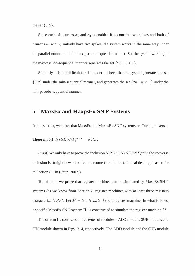
Since each of neuronsσ1 andσ2 is enabled if it contains two spikes and both of
neuronsσ1 andσ2 initially have two spikes, the system works in the same way under
the parallel manner and the max-pseudo-sequential manner.So, the system working in
the max-pseudo-sequential manner generates the set{2n | n ≥ 1}.
Similarly, it is not difficult for the reader to check that thesystem generates the set
{0, 2} under the min-sequential manner, and generates the set{2n | n ≥ 1} under the
min-pseudo-sequential manner.
5 MaxsEx and MaxpsEx SN P Systems
In this section, we prove that MaxsEx and MaxpsEx SN P systemsare Turing universal.
Theorem 5.1 NsSESNPmaxs∗
= NRE.
Proof. We only have to prove the inclusionNRE ⊆ NsSESNPmaxs∗
; the converse
inclusion is straightforward but cumbersome (for similar technical details, please refer
to Section 8.1 in (Paun, 2002)).
To this aim, we prove that register machines can be simulatedby MaxsEx SN P
systems (as we know from Section 2, register machines with atleast three registers
characterizeNRE). LetM = (m,H, l0, lh, I) be a register machine. In what follows,
a specific MaxsEx SN P systemΠ1 is constructed to simulate the register machineM .
The systemΠ1 consists of three types of modules – ADD module, SUB module, and
FIN module shown in Figs. 2–4, respectively. The ADD module and the SUB module
14

are used to simulate ADD instructions and SUB instructions of M , respectively; the
FIN module is used to output the computation result.
In general, for each registerr of M , a neuronσr in Π1 is associated whose content
corresponds to the content of the register. Specifically, ifthe registerr holds the number
n ≥ 0, then neuronσr will contain 6n+1 spikes. For each labelli of an instruction in
M , a neuronσli in Π1 is associated. Initially, all neurons have no spike, with the only
exception of neuronσl0 which is associated with the initial instructionl0 in M . Neuron
σl0 contains 2 spikes in the initial configuration, which corresponds to the fact thatM
starts a computation by applying the instruction with labell0. During a computation,
once a neuronσli receives 2 spikes, it becomes active and starts to simulate an instruc-
tion li : (OP(r), lj, lk) (OP is the operation ofADD or SUB) of M : starting with neuron
σli activated, operating neuronσr as requested byOP, then introducing 2 spikes in one
of the neuronsσlj , σlk , which becomes in this way active. When neuronσlh associated
with the halting label ofM is activated, the computation inM is completely simulated
in Π1.
Note that both in the ADD module and in the SUB module the rulesconcerning
neuronsσlj , σlk are written in the forma2 → aδ(lq) (q = j or k), because we do not
know whetherlj andlk are labels of ADD, SUB or halting instructions. That is why we
use the functionδ which is defined onH as follows:
δ(lt) =
1, if lt is the label of an ADD instruction,
2, otherwise,
wherelt ∈ H.
15
a2 a
aaa2 a
a
a3a3a2
a3a6/a6a6
a3/a
A
D
D
S
U
B
a10a6 /a6 a
a4/a
a10/a6 a5
a4a6/a6a6
a6 /a
a4/a
a4a6/a6a6
a6 /a
a4/a
⋮
a2 a2
a4/a
a2 a2
a4/a
a2 a l j a
2 a l k
l i
l i1
l i2 l i
3
r
l i2
l i4
l i5
l i6
l i11
l j l k
a5/a
a5/a
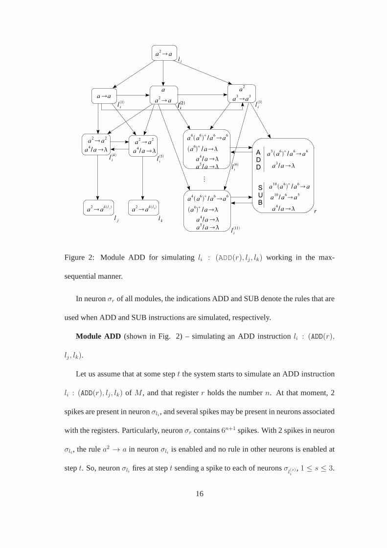
Figure 2: Module ADD for simulatingli : (ADD(r), lj, lk) working in the max-
sequential manner.
In neuronσr of all modules, the indications ADD and SUB denote the rules that are
used when ADD and SUB instructions are simulated, respectively.
Module ADD (shown in Fig. 2) – simulating an ADD instructionli : (ADD(r),
lj , lk).
Let us assume that at some stept the system starts to simulate an ADD instruction
li : (ADD(r), lj, lk) of M , and that registerr holds the numbern. At that moment, 2
spikes are present in neuronσli , and several spikes may be present in neurons associated
with the registers. Particularly, neuronσr contains6n+1 spikes. With 2 spikes in neuron
σli , the rulea2 → a in neuronσli is enabled and no rule in other neurons is enabled at
stept. So, neuronσli fires at stept sending a spike to each of neuronsσl(s)i
, 1 ≤ s ≤ 3.
16

Neuronσl(1)i
accumulates one spike, neuronσl(2)i
accumulates 2 spikes and neuronσl(3)i
accumulates 3 spikes, and so the rules in these neurons are enabled. Since the system
works in the max-sequential manner, only neuronσl(3)i
fires at stept + 1. The rule
a3 → a3 in neuronσl(3)i
is applied and 3 spikes are sent to each of neuronsσr andσl(s)i
,
6 ≤ s ≤ 11.
After 3 spikes are received from neuronσl(3)i
, neuronσr contains6n+1+3 spikes, and
so the rulea3(a6)+/a6 → a6 in neuronσr is enabled. At stept + 2, neuronσr fires by
the rulea3(a6)+/a6 → a6, consuming6n+1 spikes, leaving 3 spikes, and sending6n+1
spikes to each of the neurons to which a synapse is connected from neuronσr (because
of the exhaustive use of rules). This means that each of neurons σl(s)i
, 6 ≤ s ≤ 11,
receives6n+1 spikes, hence each of them contains6n+1 + 3 spikes at stept + 3. These
spikes will not be used in the neurons until a further spike isreceived.
Note that there may be several other neurons which receive the 6n+1 spikes from
neuronσr. If there existur ADD instructions (including ADD instructionli), andvr
SUB instructions that act on registerr, then there are in total6ur+2vr auxiliary neurons
to which a synapse is connected from neuronσr (as shown in Figs. 2 and 3, each ADD
module contains 6 auxiliary neurons to which a synapse is connected from neuronσr,
and each SUB module contains 2 auxiliary neurons to which a synapse is connected
from neuronσr). Each of the6ur + 2vr auxiliary neurons receives6n+1 spikes, hence
the forgetting rule(a6)+/a → λ is enabled. Let us recall that at stept+ 3 neuronsσl(1)i
andσl(2)i
can fire, neuronσr can fire by the rulea3 → λ. Since the system works in the
sequential manner induced by maximum spike number, the6ur+2vr auxiliary neurons
fire first, and one step is needed for the firing of a neuron. So, from stept + 3 to step
17
t + 6ur + 2vr + 2 the system removes each6n+1 spikes from the6ur + 2vr auxiliary
neurons. At stept+6ur +2vr +3, neuronσr fires by the rulea3 → λ, and so all spikes
in neuronσr are removed.
At step t + 6ur + 2vr + 4, neuronσl(2)i
fires by the rulea2 → a, sending one
spike to each of neuronsσl(s)i
, 6 ≤ s ≤ 11, and neuronsσl(3)i
, σl(4)i
, σl(5)i
. In this
way, each of neuronsσl(s)i
, 6 ≤ s ≤ 11, accumulates6n+1 + 4 spikes, and so the rule
a4(a6)+/a6 → a6 is enabled. In the following 6 steps, neuronsσl(s)i
, 6 ≤ s ≤ 11, fire
by the rulea4(a6)+/a6 → a6, where the order of firing is non-deterministically chosen.
The number of spikes in neuronσr becomes6n+2, which corresponds to the fact that
the number stored in registerr is incremented by one. After each rulea4(a6)+/a6 → a6
in neuronsσl(s)i
(6 ≤ s ≤ 11) is used, each of neuronsσl(s)i
, 6 ≤ s ≤ 11, contains 4
spikes. In the following 6 steps, neuronsσl(s)i
, 6 ≤ s ≤ 11, remove the 4 spikes by the
rulea4/a → λ. So, all auxiliary neurons to which a synapse is connected from neuron
σr return to the configuration where they contain no spike.
At stept+6ur+2vr+17, neuronσl(1)i
fires by the rulea → a, sending one spike to
each of neuronsσl(s)i
, 2 ≤ s ≤ 5. At this moment, each of neuronsσl(3)i
, σl(4)i
andσl(5)i
accumulates 2 spikes and neuronσl(2)i
accumulates one spike. Neuronsσl(2)i
andσl(3)i
return to the configuration where they contain one spike and two spikes respectively.
Neuronsσl(4)i
andσl(5)i
can fire by the rulea2 → a2. Since the system works in the max-
sequential manner, and neuronsσl(4)i
andσl(5)i
contain the same number of spikes, one of
neuronsσl(4)i
andσl(5)i
is non-deterministically chosen to fire at stept+6ur +2vr +18.
If neuronσl(4)i
fires by the rulea2 → a2 at stept + 6ur + 2vr + 18, then 2 spikes are
sent to each of neuronsσl(5)i
andσlj , enabling the rulea4/a → λ in neuronσl(5)i
and
18

the rulea2 → aδ(lj ) in neuronσlj . Neuronσl(5)i
fires by the rulea4/a → λ at step
t + 6ur + 2vr + 19 (because of the max-sequential manner), removing the spikes in
neuronσl(5)i
. Neuronσlj fires by the rulea2 → aδ(lj ) at the next step, which means that
the system starts to simulate the instructionlj of M . If neuronσl(5)i
fires by the rule
a2 → a2 at stept+6ur +2vr + 18, then the spikes in neuronσl(4)i
will first be removed
and then neuronσlk fires by the rulea2 → aδ(lk), starting to simulate the instructionlk
of M .
Therefore, the simulation of ADD instruction is correct: the system starts from
neuronσli and ends in one of neuronsσlj andσlk , non-deterministically chosen; at the
same time, the number encoded by spikes in neuronσr is incremented by one.
Module SUB (shown in Fig. 3) – simulating a SUB instructionli : (SUB(r), lj , lk).
Let us assume that at stept the system starts to simulate a SUB instructionli :
(SUB(r), lj, lk). This means that at this step neuronσli contains 2 spikes, and the neurons
associated with registers may contain several spikes. At step t, neuronσli fires by the
rulea2 → a2, sending 2 spikes to each of neuronsσl(1)i
, σl(2)i
andσl(3)i
, and so the rules in
these neurons are enabled. At stept+1, neuronσl(1)i
fires by the rulea4 → a4 (because
of the max-sequential manner), sending 4 spikes to each of neuronsσr, σl(5)i
andσl(6)i
.
A rule in neuronσr is enabled, and no rule in neuronsσl(5)i
andσl(6)i
is enabled. For
neuronσr, there are two cases.
If neuronσr contains6n+1, n > 0, spikes at stept (corresponding to the fact that
the number stored in registerr is n), then neuronσr fires by the rulea10(a6)+/a6 → a
at stept + 2. By using this rule,6n spikes are sent to neuronsσl(5)i
andσl(6)i
. At this
moment, each of neuronsσl(5)i
andσl(6)i
accumulates6n + 4 spikes. Note that neuron
19

a2 a2
a2 a2a
3/a2a
a
a4 a4a2
a3a6/a6a6
a3/a
A
D
D
S
U
B
a10a6 /a6 a
a4/a
a10/a6 a5
a5a6/a6 a6
a6 /a
a5/a
a3a2
a4/a
a4 a2
a3/a
a2 a l j a
2 a l k
l i
l i1
l i2 l i
3
r
l i7 l i
8
l i6
l j l k
a10 /a7a6
a3/a
a5a6/a
a6 /a
l i5
a10 a
a5/a
a3a3
a4 a4
l i4
Figure 3: Module SUB for simulatingli : (SUB(r), lj, lk)working in the max-sequential
manner.
σr will also send6n spikes to other auxiliary neurons to which a synapse is connected
from σr. If there existur ADD instructions andvr SUB instructions that act on register
r (including SUB instructionli), then there are in total6ur+2vr such auxiliary neurons.
So, each of the6ur + 2vr auxiliary neurons also receives6n spikes from neuronσr. In
the following 6ur + 2vr steps (from stept + 3 to stept + 6ur + 2vr + 2), each6n
spikes are removed from the6ur + 2vr auxiliary neurons by using the forgetting rule
(a6)+/a → λ, one neuron needs one step. At stept+6ur +2vr +3, the rulea4/a → λ
in neuronσr is applied, and so all spikes in neuronσr are removed.
20

At stept+6ur+2vr+4, no neuron can fire except for neuronsσl(2)i
andσl(3)i
. Since
neuronσl(2)i
contains more spikes than neuronσl(3)i
, under the max-sequential manner
neuronσl(2)i
fires by the rulea3/a2 → a at stept + 6ur + 2vr + 4, sending one spike
to each of neuronsσl(4)i
, σl(5)i
andσl(6)i
. In this way, each of neuronsσl(5)i
and σl(6)i
accumulates6n + 5 spikes, which enable the rulea5(a6)+/a6 → a6 in neuronσl(6)i
and
the rulea5(a6)+/a → λ in neuronσl(5)i
. Neuronsσl(5)i
andσl(6)i
are non-deterministically
chosen to fire at stept+6ur+2vr+5, because they contain the same number of spikes.
Actually, these two neurons will fire respectively at stept + 6ur + 2vr + 5 and step
t + 6ur + 2vr + 6. By using the rulea5(a6)+/a6 → a6 in neuronσl(6)i
, neuronσr
receives6n spikes (corresponding to the fact that the number stored in registerr is
decremented by one).
At stept + 6ur + 2vr + 7, neuronσl(6)i
removes its 5 spikes, neuronσl(3)i
fires by
the rulea2 → a2, sending 2 spikes to neuronsσl(1)i
andσl(4)i
. Neuronσl(1)i
returns to the
configuration where it contains 2 spikes, and neuronσl(4)i
accumulates 3 spikes which
enable the rulea3 → a3. At stept+6ur+2vr+8, neuronσl(4)i
fires by the rulea3 → a3,
sending 3 spikes to neuronsσl(7)i
andσl(8)i
. In the following 2 steps, neuronσl(7)i
fires
by the rulea3 → a2, and neuronσl(8)i
fires by the rulea3/a → λ respectively, where
the order of firing is non-deterministically chosen. For neuron σl(8)i
, the 3 spikes are
removed by the rulea3/a → λ. As for neuronσl(7)i
, 2 spikes are sent to neuronσlj by
the rulea3 → a2, which means that the system starts to simulate instructionlj of M .
If neuronσr contains 6 spikes at stept (corresponding to the fact that the number
stored in registerr is 0), then neuronσr fires by the rulea10/a6 → a5 at stept+2. In this
case, we can similarly check that neuronσlk becomes active at stept+ 6ur + 2vr + 11,
21

a2 a2
a4 a4a2
a3a6/a6 a6
a3/a
A
D
D
F
I
N
a4a6/a6a6
a4/a
lh
lh
1
1
a4a6/a6a6
a6 /a
lh
3
a8a6/a6 a
lh
4
a2 a
lh
5
a2 a2
lh
2
a8/aa
4/a
a a6/a6a6
aaout
a6 /aaa
Figure 4: Module FIN for outputting the result of computation working in the max-
sequential manner.
and the system starts to simulate instructionlk of M .
Therefore, the simulation of SUB instruction is correct: the system starts fromσli ,
and ends inσlj with the number encoded by spikes inσr decreased by one (if the number
stored in registerr is greater than 0), or inσlk with the number encoded by spikes inσr
keeping unchanged (if the number stored in registerr is 0). From the above explanation,
we can find that there exists no interference between two SUB modules, or between a
SUB module and an ADD module. All spikes in neurons of other modules sent by the
common neuronσr will be removed before systemΠ1 passes to the simulation of the
next instruction. Therefore, all SUB instructions can be correctly simulated.
Module FIN (shown in Fig. 4) – outputting the result of computation.
Let us assume that at stept neuronσlh in Π1 has accumulated 2 spikes and fires,
which means that the computation inM halts (that is, the halting instruction is reached).
22

We also assume that whenM halts numbern is present in register 1, so neuronσ1
contains6n+1 spikes at that moment. When neuronσlh fires, it immediately sends 2
spikes to each of neuronsσl(1)h
andσl(2)h
, enabling the rulea4 → a4 in σl(1)h
and the rule
a2 → a2 in σl(2)h
. At stept + 1, neuronσl(1)h
fires by the rulea4 → a4, sending 4 spikes
to neuronsσ1 andσl(3)h
. Neuronσ1 fires at stept + 2 by the rulea4(a6)+/a6 → a6
(because of the max-sequential manner), sending6n+1 spikes to each of neurons to
which a synapse is connected from neuronσ1. If there areu1 ADD instructions that
act on register 1 (let us recall that there is no SUB instruction that acts on register 1),
then the system has in total6u1 + 1 auxiliary neurons to which a synapse is connected
from neuronσ1, including neuronσl(3)h
in Fig. 4. At stept+3, neuronσl(3)h
accumulates
6n+1+4 spikes, while each of the other6u1 auxiliary neurons accumulates6n+1 spikes.
Neuronσl(3)h
fires at stept + 3 by the rulea4(a6)+/a6 → a6, sending6n+1 spikes to
neuronσl(4)h
, leaving 4 spikes in neuronσl(3)h
. The other6u1 neurons fire in the next6u1
steps by the rule(a6)+/a → λ, removing each6n+1 spikes from them. In the next 2
steps, the 4 spikes remaining in each of neuronsσ1 andσl(3)h
are removed by using the
rulea4/a → λ.
At stept+6u1+6, neuronσl(2)h
fires by the rulea2 → a2, sending 2 spikes to neuron
σl(4)h
. In this way, neuronσl(4)h
accumulates6n+1 +2 spikes. At stept+6u1+7, neuron
σl(4)h
fires by the rulea8(a6)+/a6 → a, sending6n spikes to neuronσl(5)h
, leaving 2 spikes
in neuronσl(4)h
. At the next step, the 2 spikes in neuronσl(4)h
are consumed by using the
rule a2 → a, sending one spike to neuronσl(5)h
, and so the rulea(a6)+/a6 → a6 in
σl(5)h
is enabled. At stept + 6u1 + 9, neuronσl(5)h
fires by the rulea(a6)+/a6 → a6,
sending6n spikes to neuronsσl(4)h
andσout. The6n spikes in neuronσout are removed
23
by the rule(a6)+/a → λ at the next step. At stept + 6u1 + 11, neuronσl(5)h
fires by
the rulea → a, sending one spike to neuronsσl(4)h
andσout. At this step, neuronσout
accumulates one spike, and neuronσl(4)h
accumulates6n + 1 spikes (these spikes will
not be used until one further spike is received). Neuronσout fires at stept+6u1+12 by
the rulea → a, so the number of spikes in neuronσl(4)h
becomes6n + 2 and one spike
is sent to the environment. In the next steps, in the system only neuronsσl(4)h
, σl(5)h
and
σout keep working. The number of spikes in neuronσl(4)h
is repeatedly divided by 6 until
it becomes 8, and for each division one spike is sent to the environment. Therefore,n
spikes in total are sent to the environment, which is exactlythe number stored in register
1 ofM at the moment when the computation ofM halts.
From the above description, it is not difficult for the readerto check that the register
machineM can be correctly simulated by the SN P systemΠ1 with exhaustive use of
rules working in the max-sequential manner. 2
The system constructed in the proof of Theorem 5.1 works in the max-sequential
manner, where one of the active neurons is non-deterministically chosen to fire when the
system has several active neurons with the maximum number ofspikes, which makes
the system non-deterministic. If we consider the system works in the max-pseudo-
sequential manner, then the non-determinism from choosingone of the active neurons is
lost. In what follows, we will show that SN P systems without such a non-determinism
are still Turing universal. That is, the following corollary holds.
Corollary 5.1 NsSESNPmaxps∗
= NRE.
24

a2 a
aaa2 a
a
a3a3a2
a3a6/a6a6
a3/a
A
D
D
S
U
B
a10a6 /a6 a
a4/a
a10/a6 a5
a4a6/a6a6
a6 /a
a4/a
a4a6/a6a6
a6 /a
a4/a
⋮
a2 a2
a
aa
a2/a
a2 a l j a
2 a l k
l i
l i1
l i2 l i
3
r
l i2
l i5
l i6
l i6
l i11
l j l k
a5/a
a5/a
a2 a2
a2 a
l i4
aaaa
l i7
l i8
Figure 5: Module ADD for simulatingli : (ADD(r), lj, lk) working in the max-pseudo-
sequential manner.
Proof. We can check that, under the max-pseudo-sequential manner,the SUB mod-
ule shown in Fig. 3 can also correctly simulate a SUB instruction, and the FIN module
shown in Fig. 4 outputs exactly the number stored in register1 at the moment when the
register machine halts. So, in order to prove Corollary 5.1 we only need to construct an
ADD module to simulate the ADD instruction. The ADD module can be constructed
by slightly modifying the ADD module shown in Fig. 2, which isdepicted in Fig. 5.
Similar to the ADD module shown in Fig. 2, in the module from Fig. 5 the num-
ber of spikes in neuronσr is first multiplied by 6 (corresponding to the fact that the
number stored in registerr is incremented by one), then neuronσlj or σlk is non-
deterministically chosen to fire. The firing of neuronsσlj andσlk is achieved in the
25

following way. After finishing the process of multiplying the number of spikes in neu-
ronσr by 6, neuronσl(4)i
accumulates exactly 2 spikes (one spike is received from neu-
ronσl(1)i
and the other spike is received fromσl(2)i
). So, neuronσl(4)i
can fire by the rule
a2 → a2 or a2 → a, non-deterministically chosen. If the rulea2 → a2 in neuronσl(4)i
is applied, then 2 spikes are sent to neuronsσl(5)i
andσl(6)i
, enabling the rulea2 → a2 in
σl(5)i
and the rulea2/a → λ in σl(6)i
. Under the max-pseudo-sequential manner, the two
rules are applied at the same step. The use of rulea2/a → λ removes 2 spikes from
σl(6)i
, while the use of rulea2 → a2 in σl(5)i
activates neuronσlj , which means that the
system starts to simulate the instructionlj of M . If the rulea2 → a in neuronσl(4)i
is
applied, then one spike is sent to neuronsσl(5)i
andσl(6)i
. At the next step, neuronsσl(5)i
andσl(6)i
fire at the same time (because of the max-pseudo-sequential manner), remov-
ing the spike from neuronσl(5)i
and sending one spike to neuronsσl(7)i
andσl(8)i
from
σl(6)i
. Each of neuronsσl(7)i
andσl(8)i
sends one spike to neuronσlk , and so neuronσlk is
activated and the system starts to simulate the instructionlk of M . 2
It remains open whether we can constructΠ1 in such a way that the maximum num-
ber of spikes appears in only one neuron during every computation (in such a system,
the max-sequential and max-pseudo-sequential manners would coincide).
6 MinsEx and MinpsEx SN P Systems
In the ADD module shown in Figure 2, after neuronσli fires, neuronsσ(1)li
, σ(2)li
, σ(3)li
become active. By the max-sequential manner, only after neuronσ(3)li
fires, neuronσ(2)li
can fire, then neuronσ(1)li
fires. When neuronσ(3)li
fires, the system starts the process
26
a3a
aa
a a5 /a5a5
a
A
D
D
S
U
B
a7a5 /a5 a
a2/a
a7/a5a4
a2a5/a5a5
a5 /a
a2/a
a2a5/a5a5
a5 /a
a2/a
⋮
aa
a2/a
aa
a2/a
a3a l j a
3a lk
l i
l i1
r
l i16 l i
17
l i7
l i11
l j l k
a4/a
a4/a
a6a5/a5 a5
l i2
a6a
a a5/a5a
l i3a
2/a
a5 /a
l i4
aa
a8a5/a5 a5
l i6
a8a
a a5/a5a
l i5a
2/a
a5 /a
l i12
aaaa
l i14
aa
l i13
a4/a
a4/a
a5 /a
a5 /a
aa
l i15
a3a2
l i18
a2/a a
2/a
a2/a
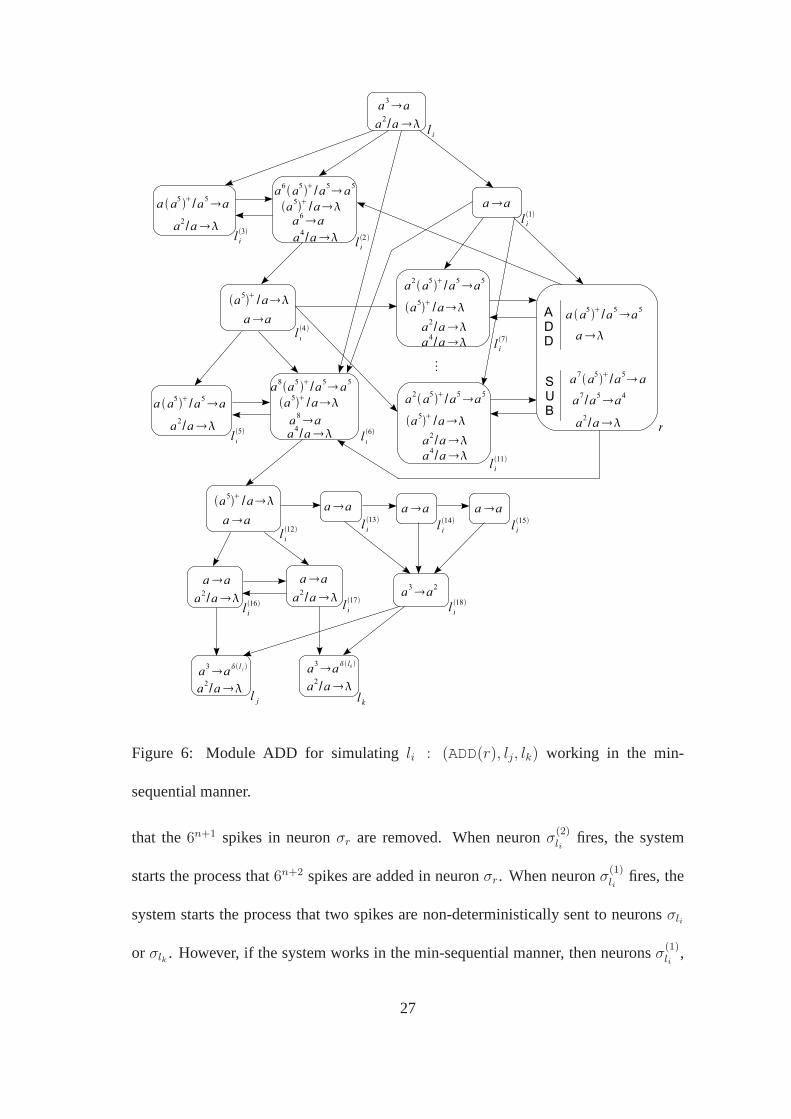
Figure 6: Module ADD for simulatingli : (ADD(r), lj, lk) working in the min-
sequential manner.
that the6n+1 spikes in neuronσr are removed. When neuronσ(2)li
fires, the system
starts the process that6n+2 spikes are added in neuronσr. When neuronσ(1)li
fires, the
system starts the process that two spikes are non-deterministically sent to neuronsσli
or σlk . However, if the system works in the min-sequential manner,then neuronsσ(1)li
,
27
a3a2
a2 a2
a a5/a5a5
a
A
D
D
S
U
B
a7a5/a5a
a2/a
a7/a5a4
a4a5/a5a5
a5 /a
a3a l j a
3a lk
l i
l i1
r
l i13
l j l k
a8a5
a4a5 /a
a5 /a
l i5
a8a
a4/a
a7a5/a5 a5
a5 /a
l i2
a7a2
a4/a
a5 /a
a2 a2
l i4
a6a2
a2a5/a5a
a4/a
l i3
a11a5 /a5 a5
l i6
a11 a2
a4/a
a2a5 /a5a
a4/a
a5 /a
a2 a2
a3a2
a2 a
l i9
aa
a2/a
l i14
a2 aa
l i16
a2 a2
l i11
a2 a2
l i12
a2 a2
l i10
a6a2
l i15
l i7
l i8
a2/a a
2/a
a2/a
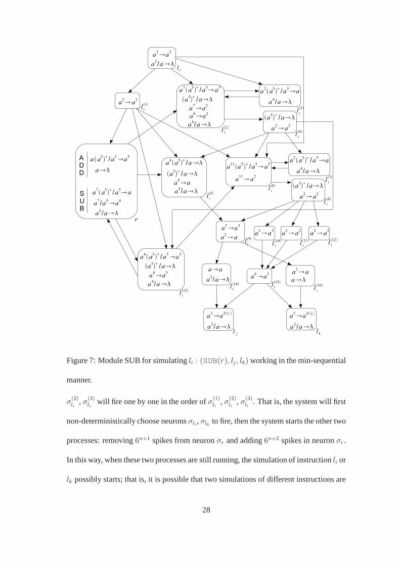
Figure 7: Module SUB for simulatingli : (SUB(r), lj, lk) working in the min-sequential
manner.
σ(2)li
, σ(3)li
will fire one by one in the order ofσ(1)li
, σ(2)li
, σ(3)li
. That is, the system will first
non-deterministically choose neuronsσli , σlk to fire, then the system starts the other two
processes: removing6n+1 spikes from neuronσr and adding6n+2 spikes in neuronσr.
In this way, when these two processes are still running, the simulation of instructionli or
lk possibly starts; that is, it is possible that two simulations of different instructions are
28

a3a2
a a5/a5a5
a
A
D
D
F
I
N
a2a5/a5a5
a2/a
lh
1
a2a5/a5a5
a5 /alh
5
a2 a2
lh
1
a2/a
a9a5/a5 a5
lh
2
a5 /a
a9a2
a2a5/a5a
lh
3a4/a
a5 /a
lh
4 a2 a2
a7a5/a5 a
a2a
lh
6a7/a
a a5/a5a5
aa
lh
7
a6a5/a5 a5
a6a2
lh
8
a a5/a5a
a3/a
lh
9
a5 /a
a2a2
a
out
a4 a
lh
10
a2 a2
lh
12
a2 a2
lh
11
Figure 8: Module FIN for ending the computation working in the min-sequential man-
ner.
in process at the same time, which will cause undesired simulation steps. Therefore, in
the min-sequential manner, the system constructed in the proof of Theorem 5.1 cannot
correctly simulate a register machine.
In what follows, by constructing appropriate SN P systems tosimulate register ma-
chines, we prove that MinsEx and MinpsEx SN P systems are alsoTuring universal.
Theorem 6.1 NsSESNPmins∗
= NRE.
Proof. The proof is similar to the one of Theorem 5.1. We construct anMinsEx SN
P systemΠ2 to simulate a register machineM . The systemΠ2 consists of three types
29

a3a
aa
a a5 /a5a5
a
A
D
D
S
U
B
a7a5 /a5 a
a2/a
a7/a5a4
a2a5/a5a5
a5 /a
a2/a
a2a5/a5a5
a5 /a
a2/a
⋮
a2 a
a
aa
a2/a
a3a l j a
3a lk
l i
l i1
r
l i16 l i
18
l i7
l i11
l j l k
a4/a
a4/a
a6a5/a5 a5
l i2
a6a
a a5/a5a
l i3a
2/a
a5 /a
l i4
aa
a8a5/a5 a5
l i6
a8a2
a a5/a5a
l i5a
3/a
a5 /a
l i12
a2 a2
aa
l i14
a2 a
l i13
a4/a
a4/a
a5 /a
a5 /a
aal i15
a3a2
l i19
a2/a a
2/a
a2/a
a2 a2
a2 a
l i17
Figure 9: Module ADD for simulatingli : (ADD(r), lj, lk) working in the min-pseudo-
sequential manner.
of modules – ADD module, SUB module, and FIN module shown in Figs. 6, 7 and 8,
respectively. In the modules, the functionδ is defined as in the proof of Theorem 5.1.
The numbern (n ≥ 0) stored in registerr is encoded as5n+1 spikes in neuronσr, and
each of neurons associated with an instruction is activatedwhen it contains 3 spikes.
30

In ADD module shown in Fig. 6, when neuronσl(1)i
fires, the system starts to the
following two processes: removing5n+1 spikes from neuronσr and adding5n+2 spikes
to neuronσr; neuronsσl(s)i
, 7 ≤ s ≤ 11, take care of the adding process. When neuron
σl(2)i
fires, the system starts to non-deterministically send three spikes to neuronσli or
σlk , which is implemented by neuronsσl(4)i
, σl(5)i
, σl(6)i
, andσl(s)i
, 12 ≤ s ≤ 18.
In the SUB module shown in Fig. 7, when neuronσl(1)i
fires, the system starts to
test whether neuronσr contains 5 spikes (i.e., the number in registerr of M is 0). If
neuronσr contains 5 spikes, thenσl(5)i
fires sending one spike to neuronσl(9)i
; with the
collaborative work of neuronsσl(s)i
, 2 ≤ s ≤ 16, s 6= 9, neuronσli receives three spikes,
while neuronσlk receives no spike. If neuronσr contains5n+1, n ≥ 1, spikes, thenσl(5)i
will not fire; the result of the collaborative work of neuronsσl(s)i
, 2 ≤ s ≤ 16, is that
neuronσli receives no spike, while neuronσlk receives three spikes.
In FIN module shown in Fig. 8, the auxiliary neuronsσl(s)i
, 1 ≤ s ≤ 12, implement
the process: for every 5 spikes in neuronσ1, neuronσout will receive 4 spikes and fire
sending one spike into the environment.
Similar to the proof of Theorem 5.1, we can check the work of modules ADD, SUB,
and FIN step by step. We here omit the details. 2
As in the case of the max-pseudo-sequential manner, we can prove that the univer-
sality result holds for MinpsEx SN P systems. That is, the following corollary holds.
Corollary 6.1 NsSESNPminps∗
= NRE.
Proof.We can check that the SUB module from Fig. 7 and the FIN module from Fig.
8 can also correctly work in the min-pseudo-sequential manner. A slightly modified
31

version of the ADD module from Fig. 6 can correctly simulate an ADD instruction,
which is shown in Fig. 9. 2
It remains open whether we can constructΠ2 in such a way that the minimum num-
ber of spikes appears in only one neuron during every computation (in such a system,
the min-sequential and min-pseudo-sequential manners would coincide).
7 Conclusions and discussions
In this work, we investigated the computation power of MaxsEx, MaxpsEx, MinsEx,
and MinpsEx SN P systems. We proved that all of the systems areTuring universal.
The results show that the power of SN P systems is not reduced if some restrictions are
imposed on the working manner of neurons and rules of the systems, or the systems
do not have the non-determinism resulting from the way of choosing one of the active
neurons with maximum or minimum spikes to fire.
In the SN P systems constructed in this work, forgetting rules are used, but the
feature of delay is not used. It is of interest to investigatethe contribution of the feature
of delay and forgetting rules to the computation power. Future investigations in this
aspect include whether MaxsEx, MaxpsEx, MinsEx, and MinpsEx SN P systems have
the same computation power when forgetting rules (and delays) are removed.
In this work, the result of a computation is defined as the number of spikes sent to the
environment by the output neuron. However, in neural computation based on spikes, it
is usual to use time as data support. So, it is natural to definethe result of a computation
as the time associated with spikes, for example, the interval of time elapsed between
32

the first two consecutive spikes sent out by the output neuron. The computation power
of MaxsEx, MaxpsEx, MinsEx, and MinpsEx SN P systems deserves to be investigated
when the result of a computation is defined as the interval of time elapsed between the
first two consecutive spikes sent out by the output neuron.
Acknowledgment
This work was supported by National Natural Science Foundation of China (61033003,
91130034, 61272152 and 61320106005), Ph.D. Programs Foundation of Ministry of
Education of China (20100142110072 and 2012014213008), and Natural Science Foun-
dation of Hubei Province (2011CDA027), Natural Science Foundation of Anhui Higher
Education Institutions of China (KJ2012A010 and KJ2012A008), and Scientific Re-
search Foundation for Doctor of Anhui University under Grant 02203104.
A series of suggestions made by the anonymous referees, who carefully read the
letter, are gratefully acknowledged.
References
Cavaliere, M., Ibarra, O. H., Paun, G., Egecioglu, O., Ionescu, M., & Woodworth, S.
(2009). Asynchronous spiking neural P systems.Theoretical Computer Science, 410,
2352 – 2364.
Chen, H., Freund, R., Ionescu, M., Paun, G., & Perez-Jimenez, M. J. (2007). On string
languages generated by spiking neural P systems.Fundamenta Informaticae, 75, 141
– 162.
33
Chen, H., Ionescu, M., Ishdorj, T. -O., Paun, A., Paun, G.,& Perez-Jimenez, M. J.
(2008). Spiking neural P systems with extended rules: universality and languages.
Natural Computing, 7, 147 – 166.
Freund, R. (2005). Asynchronous P systems and P systems working in the sequential
mode. In Mauri, G., Paun, G., Perez-Jimenez, M. J., Rozenberg, G., & Salomaa, A.,
editors,Membrane Computing, Volume 3365 ofLecture Notes in Computer Science,
pages 36 – 62. Springer-Verlag, Berlin, Germany.
Ibarra, O. H., Paun, A., & Rodrıguez-Paton, A. (2009). Sequential SN P systems based
on min/max spike number.Theoretical Computer Science, 410, 2982 – 2991.
Ibarra, O. H., Woodworth, S., Yu, F., & Paun, A. (2006). On spiking neural P systems
and partially blind counter machines.Proceeding UC’06 Proceedings of the 5th in-
ternational conference on Unconventional Computation, pages 113 – 129, Springer-
Verlag Berlin, Germany.
Ionescu, M., Paun, G., & Yokomori, T. (2006). Spiking neural P systems.Fundamenta
Informaticae, 71, 279 – 308.
Ionescu, M., Paun, G., & Yokomori, T. (2007). Spiking neural P systems with an
exhaustive use of rules.International Journal of Unconventional Computing, 3, 135
– 154.
Ishdorj, T. -O., Leporati, A., Pan, L., Zeng, X., & Zhang, X. (2010). Deterministic solu-
tions to QSAT and Q3SAT by spiking neural P systems with pre-computed resources.
Theoretical Computer Science, 411, 2345 – 2358.
34
Minsky, M. (1967). Computation – Finite and Infinite Machines. Prentice Hall, Inc.,
Upper Saddle River, NJ, USA.
Pan, L., Wang, J., & Hoogeboom, H. J. (2012). Spiking neural Psystems with astro-
cytes.Neural Computation, 24, 805 – 825.
Pan, L., Zeng, X., & Zhang, X. (2011). Time-free spiking neural P systems.Neural
Computation, 23, 1320 – 1342.
Paun, A., & Paun, G. (2007). Small universal spiking neural P systems.BioSystems,
90, 48 – 60.
Paun, G. (2000). Computing with membranes.Journal of Computer and System Sci-
ences, 61, 108 – 143. (See also Turku Center for Computer Science – TUCSReport
No. 208, 1998).
Paun, G. (2002).Membrane Computing. An Introduction. Springer-Verlag, Berlin,
Germany.
Paun, G., & Perez-Jimenez, M. J. (2009). Spiking neural Psystems. recent results,
research topics.Algorithmic Bioprocesses (Natural computing series), 5, 273 – 291.
Paun, G., Rozenberg, G, & Salomaa, A. editors (2010).The Oxford Handbook of Mem-
brane Computing. Oxford University Press, Inc., New York, NY, USA.
Rozenberg, G., & Salomaa, A., editors (1997).Handbook of Formal Languages.
Springer-Verlag, Berlin, Germany.
Wang, J., Hoogeboom, H. J., Pan, L., Paun, G., & Perez-Jim´enez, M. J. (2010). Spiking
neural P systems with weights.Neural Computation, 22, 2615 – 2646.
35

Xu, L., & Jeavons, P., (2013). Simple neural-like P systems for maximal independent
set selection.Neural Computation, 25, 1642 – 1659.
Zhang, X., Luo, B., Fang, X., & Pan, L. (2012). Sequential spiking neural P systems
with exhaustive use of rules.BioSystems, 108, 52 – 62.
Zhang, X., Zeng, X., & Pan, L. (2008). On string languages generated by spiking neural
P systems with exhaustive use of rules.Natural Computing, 7, 535 – 549.
36