on mathematicon mathematicalaallal modeling of shaped ...18367/fulltext01.pdf · on mathematicon...
TRANSCRIPT

On mathematicOn mathematicOn mathematicOn mathematicalalalal modeling of shaped charge modeling of shaped charge modeling of shaped charge modeling of shaped charge penetrationpenetrationpenetrationpenetration
Tudor Clipii
Maskinkonstruktion
Examensarbete
Institutionen för ekonomisk och industriell utveckling
ISRN LIU-IEI-TEK-A--08/00419--SE

ABSTRACT 1
FOREWORD 2
INTRODUCTION 3
THE SHAPED CHARGE 3
THE STUDY CONTEXT 4
PROBLEM SETTING 5
THE STANDARD THEORY 5
SUGGESTED ALTERNATIVE THEORY 6
TASK 6
TOOL 6
SETUP 8
GOVERNING EQUATIONS 8
DISCRETIZATION 9
Grid types 9
Grid choice 10
Meshing 10
MATERIAL MODELING 12
Models available 12
Model selection 13
GEOMETRIC SETUP 16
Symmetry 16
Shape 16
DATA INTERPRETATION 17
Program termination 17
Post processor examination 17
COMPUTATIONS 19
Computation 1: Element spacing 0 mm 19
Computation 2: Element spacing 2 mm 22
Computation 3: Element spacing 13 mm 26
Computations 4 and 5 30
CONCLUSIONS 31
RESULT 31
FURTHER RESEARCH TOPICS - SUGGESTIONS 34
Extreme inter-particle spacing 34
Multiple projectile jet 35
Entire SC jet 35
Material strength modeling results 36
REFERENCES 37

Tudor Clipii On mathematical modeling of
shaped charge penetration
1/39
Abstract
Shaped charges are a well established type of projectile, subjected to a lot of research
ever since emerging as a viable technology in the 1940s. The penetration achieved by
shaped charges decreases with increased standoff distance. This is often attributed to
the shaped charge jet losing its coherence. The Swedish Defence Research Agency
however, noted no such loss of coherence in its experiments. An alternative
explanation to the decrease of penetration was instead proposed. The object of this
thesis was to investigate this proposed theory. To this end, the hydrocode Autodyn
was used, modelling the impact of a high-velocity projectile into a generic target and
analysing the resulting behaviour of the target. Several setups were used and several
parameters were considered when evaluating the results. The conclusion of this thesis
is that the alternative explanation offered is not supported by the observed behaviour
of the target in the computer model.

Tudor Clipii On mathematical modeling of
shaped charge penetration
2/39
Foreword
The entire body of investigative work contained in this thesis took place in the spring
of 2002 at the Grindsjön facility of the Swedish Defence Research Agency. The bulk
of the thesis text was authored during that period as well. I want to take the
opportunity to thank Gunnar Wijk of said agency for his support and willingness to
answer a never ending stream of questions. His high regard for the analytical
calculations behind all theory has been a source of inspiration ever since.
The work on the report was however interrupted in its final stages by events outside
my control. It was resumed almost six years later and completed only thanks to the
support of Lars Johansson of University of Linköping. Lars patience and willingness
to read through yet another draft were key to the completion of this thesis.
Last, but not least, I want to thank my wife Yeliz for her support and understanding
during the entire period of finalizing the report. It would have never been finished
without it.
Tudor Clipii,
Södertälje 2008
Tudor Clipii
Introduction
The shaped charge
Over the last century, the armored vehicle has firmly established its presence on most
battlefields as an important, often decisive, feature. Naturally, an equally impressive
array of countermeasures has been developed over the years. Although the detail
diversity in this department is great, all methods of defeating armor rely either on the
kinetic energy imparted to the round by the firing gun or the chemical energy carried
within the round itself. This
There are several ways to extract the chemical energy stored in a warhead and direct it
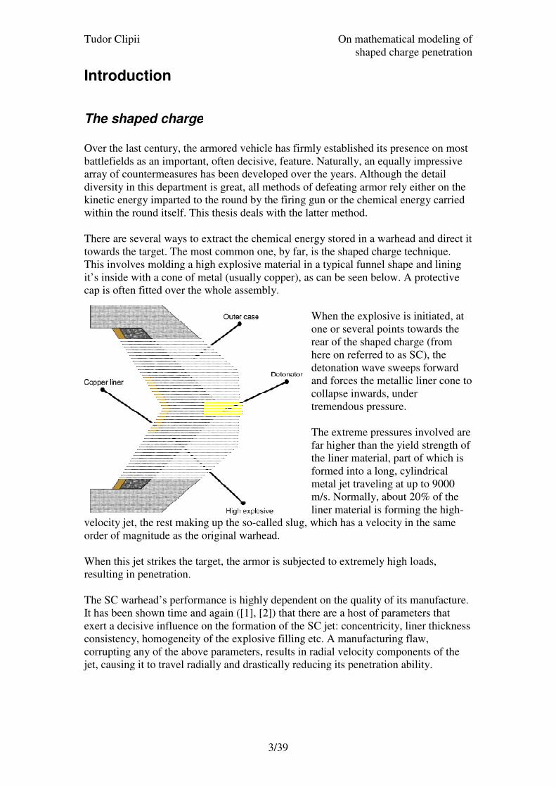
towards the target. The most common one, by far, is the shaped charge technique.
This involves molding a high explosive material in a typical funnel shape and lining
it’s inside with a cone of metal (usually copper), as can be seen below. A protective
cap is often fitted over the whole assembly.
velocity jet, the rest making up the so
order of magnitude as the original warhead.
When this jet strikes the target, the armor is subjected to extremely high loads,
resulting in penetration.
The SC warhead’s performance is highly dependent on the quality of
It has been shown time and again ([1], [2]) that there are a host of parameters that
exert a decisive influence on the formation of the SC jet: concentricity, liner thickness
consistency, homogeneity of the explosive filling etc. A manufacturing flaw,
corrupting any of the above parameters, results in radial velocity components of the
jet, causing it to travel radially and drastically reducing its penetration ability.
On mathematical mod
shaped charge penetration
3/39
The shaped charge
Over the last century, the armored vehicle has firmly established its presence on most
battlefields as an important, often decisive, feature. Naturally, an equally impressive
array of countermeasures has been developed over the years. Although the detail
iversity in this department is great, all methods of defeating armor rely either on the
kinetic energy imparted to the round by the firing gun or the chemical energy carried
within the round itself. This thesis deals with the latter method.
ral ways to extract the chemical energy stored in a warhead and direct it
towards the target. The most common one, by far, is the shaped charge technique.
This involves molding a high explosive material in a typical funnel shape and lining
a cone of metal (usually copper), as can be seen below. A protective
cap is often fitted over the whole assembly.
When the explosive is initiated,
one or several points towards the
rear of the shaped charge (from
here on referred to as SC), the
detonation wave sweeps forward
and forces the metallic liner cone to
collapse inwards, under
tremendous pressure.
The extreme pressures involved are
far higher than the yield strength of
the liner material, part of which is
formed into a long, cylindrical
metal jet traveling at up to 9000
m/s. Normally, about 20% of the
liner material is forming the high
velocity jet, the rest making up the so-called slug, which has a velocity in the same
order of magnitude as the original warhead.
target, the armor is subjected to extremely high loads,
The SC warhead’s performance is highly dependent on the quality of its
It has been shown time and again ([1], [2]) that there are a host of parameters that
t a decisive influence on the formation of the SC jet: concentricity, liner thickness
consistency, homogeneity of the explosive filling etc. A manufacturing flaw,
corrupting any of the above parameters, results in radial velocity components of the
sing it to travel radially and drastically reducing its penetration ability.
On mathematical modeling of
shaped charge penetration
Over the last century, the armored vehicle has firmly established its presence on most
battlefields as an important, often decisive, feature. Naturally, an equally impressive
array of countermeasures has been developed over the years. Although the detail
iversity in this department is great, all methods of defeating armor rely either on the
kinetic energy imparted to the round by the firing gun or the chemical energy carried
ral ways to extract the chemical energy stored in a warhead and direct it
towards the target. The most common one, by far, is the shaped charge technique.
This involves molding a high explosive material in a typical funnel shape and lining
a cone of metal (usually copper), as can be seen below. A protective
When the explosive is initiated, at
one or several points towards the
rear of the shaped charge (from
here on referred to as SC), the
ation wave sweeps forward
and forces the metallic liner cone to
collapse inwards, under
tremendous pressure.
The extreme pressures involved are
far higher than the yield strength of
the liner material, part of which is
formed into a long, cylindrical
al jet traveling at up to 9000
m/s. Normally, about 20% of the
liner material is forming the high-
called slug, which has a velocity in the same
target, the armor is subjected to extremely high loads,
its manufacture.
It has been shown time and again ([1], [2]) that there are a host of parameters that
t a decisive influence on the formation of the SC jet: concentricity, liner thickness
consistency, homogeneity of the explosive filling etc. A manufacturing flaw,
corrupting any of the above parameters, results in radial velocity components of the
sing it to travel radially and drastically reducing its penetration ability.

Tudor Clipii On mathematical modeling of
shaped charge penetration
4/39
The study context
The distribution of velocity along the jet is not uniform, but decreases linearly from
the tip towards the tail. This causes the jet to elongate over time, eventually breaking
up into smaller elements, with growing gaps in between.
The distance between the target and the point where the warhead is detonated is
known as the standoff distance and has a crucial influence on the amount of armor
penetrated. This distance is measured in calibers of the SC. The term caliber refers to
the external diameter of the explosive cone. Thus, 3calibers would mean 3 x 45 = 135
mm for a SC with 45 mm caliber. A typical standoff-penetration curve, describing the
relationship between the two, is described in [4].
It can readily be seen that an optimal standoff exists, usually around 4-5 warhead
calibers, resulting in maximum penetration. For standoffs greater than the optimal
value, penetration decreases fast.
In the theory of the field, there are a number of accepted explanations to this decrease
in penetration, usually claiming that rotation about an axis orthogonal to the direction
of the jet causes the fragments to his the target at various angles creating wider but
less deep holes. While this phenomenon certainly can be observed for warheads of
low to medium quality it is found in [3] that this is not the case for high quality
shaped charges. Apparently, after 10+ calibers of flight, the jet can still be reasonably
aligned. However, even these high quality shaped charges experience the same
reduction in penetration ability with increased detonation distance beyond optimum
standoff, albeit this effect is delayed for a couple of calibers.
This study is dedicated to examining a new explanation for this reduction of
penetration beyond optimum standoff, as put forward in [3].
Tudor Clipii On mathematical modeling of
shaped charge penetration
5/39
Problem setting
The standard theory
In the standard theory of the field, such as [1], [2], several post formation effects are
discussed. The velocity of the fragments is nearly constant, as the travelling time is
extremely short (tenths of milliseconds). Thus the kinetic energy of the jet at the time
of impact will be close to the initial kinetic energy, imparted to the jet on formation.
The reduction in penetration beyond optimum standoff, found in every experiment,
cannot be interpreted as loss of kinetic energy and requires an explanation. A number
of models have evolved to account for this phenomenon. Most evolve around the
“drifting and tumbling” of the jet particles as put forward in [2]. This motion would
cause the particles to strike the target at unfavorable angles, allowing only a small part
of their kinetic energy to contribute to the penetration depth (the rest resulting in
widening the hole entrance).
The exact nature of this set of motions has also been investigated quite extensively in
the late 70’s and throughout the 80’s, in studies such as [9]. The conclusion these
different research teams reached were somewhat similar: the critical factor in the
penetration reduction being discussed is a result of the “drifting and tumbling” of the
jet particles. More specific, small manufacturing errors in the SC result in forces
acting on the jet in directions orthogonal to the symmetry axis. These forces result in
sideways translation and rotation of the individual jet particles.
In one of these experiments [8] it was found that the results confirm the team’s
assumption that jet elements behave in a similar manner to cylindrical rods subject to
aerodynamic forces. The equation governing this motion is derived from the moment
law:
θθβθ cossin 2=&& where θ is the angle of rotation counterclockwise from the flight axis, where
yairD IDLVC 22
4
1ρβ =
CD is the drag coefficient at cross flow perpendicular to the flight axis. Here, V is the
flight velocity, L is the length and D the diameter of the jet particle in question.
The above model would suggest an effect that should be clearly visible on X-ray
photographs of the particulated jet beyond optimum standoff.
However, this effect is not readily identifiable on such X-ray photographs1, taken at
the Swedish Defence Agency’s facility in Grindsjön. The photographs in question
pictured 45mm precision SCs, in the fully particulated phase of the jet. In these
1 See Appendix 1

Tudor Clipii On mathematical modeling of
shaped charge penetration
6/39
photographs the particles do not appear to be tumbling, or move sideways, despite
being well beyond optimum standoff distance.
Suggested alternative theory
This realization led Gunnar Wijk, from the Swedish Defence Research Agency
(SDRA) to propose a different mathematical explanation to the reduction of
penetration beyond optimum standoff. His proposal suggests that the energy losses
that occur due to ‘the increased generation of elastic waves in the target’ are the main
reason for this reduction.
Mathematically, this new model was inspired by the equations normally used to
describe percussive breaking of concrete. These equations described the motion of an
elastic stress wave traveling along a steel rod, resulting in penetration of the concrete
block. If the concrete was given time to recover from the initial elastic compression, it
had to be compressed all over again resulting in much larger total energy required to
achieve the intended breaking.
Making an analogy to the rod penetration model (used to describe SC jet penetration,
among other things), Wijk concluded that this could be a reason to the reduction of
penetration above optimum standoff obvious in any SC experiment.
In [3], it was assumed that the target material has enough time to achieve some degree
of relaxation from the elastically compressed state it is in after the penetration of the
first particle, before the next one impacts. This assumption is vital to the hypothesis
put forward by Wijk.
Task
The purpose of this investigation was to ascertain whether the alternative theory
summarized above is consistent with results obtained by numerical simulations of SC
jet impact.
In order to achieve this goal, a simulation of a number of SC elements with a very
large (large relative air gaps in “normal” SC jets) air gap was to be run. The elements
in question would be perfectly aligned and not subjected to any acceleration (angular
or otherwise) or disturbance. This should, according to the presented alternative
theory, lead to a significant reduction in penetration, reduction in some degree
proportional to the size of the air gap. However, as standard theory is basing its
explanation of the phenomenon on such movements, a perfectly aligned segmented
SC jet should penetrate at least2 as much as a continuous jet of similar kinetic energy.
Tool
In order to simulate a SC jet and its impact, the simulation code Autodyn was used.
2 A slight increase in penetration performance might actually be expected, in agreement with standard
segmented projectile theory, which will be discussed in detail later on

Tudor Clipii On mathematical modeling of
shaped charge penetration
7/39
SC jet impacts are highly dynamic phenomena, because of the very high rates of
material flow, which make static assumptions rather wide off the mark. The inertial
effects dominate the process (unlike lower velocity impact, which is dominated by
material strength). In order to simulate such a high velocity penetration, one has to
solve the equations describing the conservation of mass, momentum and energy,
coupling them with a material model. The system of differential equations that results
from such an approach is (usually) too complex to be solved analytically. Thus, a
number of methods for approximated numerical solutions have been developed over
the years. Computer programs implementing such algorithms are known as
hydrocodes.
Currently, a number of such hydrocodes are commercially available. FOI has had a
tradition of using Autodyn™ from Century Dynamics, in both two- and three-
dimensional studies. It is a very capable piece of software, allowing for several
algorithms (each with its own discretization method). Also good analysis tools are
provided for post processor work, leaving the user with many and varied ways to
extract data from simulation runs. These were the reasons behind the selection of
Autodyn™ as the examination tool for the investigation at hand.

Tudor Clipii On mathematical modeling of
shaped charge penetration
8/39
Setup
As is always the case with technical calculations, a number of decisions had to be
made as to the exact setup of the calculations. In order to explain these, a further
explanation of the principles of dynamic impact modeling software is in order.
Governing equations
A continuum under impact, exposed to high loads with great distortion as result,
cannot be analyzed using static analysis relations. It is necessary to take into account:
• Mass conservation
• Linear momentum conservation
• Angular momentum conservation
• Energy conservation
• Volumetric response of materials
• Deviatoric response of materials
• Failure criteria and postfailure prescriptions (if applicable)
The above conditions yield a system of partial differential equations that is normally
impossible to solve analytically.
The principle behind any finite element algorithm is to divide the material continuum
into a finite number of separate elements, which interact with each other in a finite
number of points, called nodes. The net result of this discretization is a number of
solvable equations. The elements, also called cells, taken together form the so-called
mesh.
A set of initial conditions is specified for each mesh element. Advancing the time step
incrementally allows for a solution of the material’s movement and state over time.
Tudor Clipii On mathematical modeling of
shaped charge penetration
9/39
Discretization
The final number of equations to be solved is a function of the grid type, element size,
model size and geometry. The number of iterations needed to compute a certain event
with the duration T is T
t∆, where ∆t is the time increment, which depends on several
factors (mainly the size of the smallest cell in the grid). These numbers are interesting
as they give an estimate of the computer power and time needed to solve a given
problem.
Grid types
Two basic solution methods are in use: the Lagrangian and the Eulerian types. Each
has its advantages and disadvantages, so a compromise is always involved when
choosing the mesh type to be used in a given context.
The Lagrangian mesh type defines each material particles position at time t as a
function of the particles initial position (a1, a2, a3) and time t. The grid is locked onto
the material and moves with it. Thus, distortion in the material is reflected in equally
distorted cells. Since the time step is decreases with the width of the cells, a highly
distorted cell could result in extremely small time steps.
In problems characterized by high material flow, the cell distortion is a potentially
serious problem. Several techniques exist to address this issue. The goal is to
eliminate or enlarge the cell(s) whose dimension(s) limit the timestep. This can be
done in two basic ways: rezoning and erosion. When rezoning, the nodes (cell
boundaries) are repositioned in order to eliminate the more eccentric shaped cells.
This, however, can take a lot of time, as it can be necessary to perform this operation
rather often if the distortions are large, and the operation is seldom completely
automated, thus requiring operator intervention.
If the high rate of flow is a local phenomenon, affecting only a few cells, erosion may
be employed. This is a technique that automatically eliminates cells whose size
shrinks below a certain minimum. It does have the huge drawback that it is not a
physically consistent method, shifting around mass without really accounting for it.
Still, if the number of cells involved is low, and the cells are small enough, credible
results are still possible, and the CPU time used up is comparatively low.
The other major type of mesh is the Euler grid. In Eulerian notation, the grid is
considered fixed and the material flows through it. This eliminates the problem of cell
distortion with moving material. However, as the contents of a cell are not constant,
more bookkeeping is necessary for each time step, considerably increasing CPU time
requirements. Another problem is the difficulty in defining material boundaries, as
different materials tend to mix in the same cell, along the line where the materials
interact. These mixed cells require special techniques to be handled, and do not define
the exact borders between the mixed contents, only a mass ratio. This results in some
difficulty, for instance in establishing the depth of a penetration. However, the
Eulerian system has the advantage of not taking any shortcuts around the laws of
Tudor Clipii On mathematical modeling of
shaped charge penetration
10/39
physics. The mass is there and so is the energy, fulfilling all balance requirements.
The only simplification is the discretization itself, and the error is proportional to the
size of the grid elements (actually only down to the point where truncation errors
become so large, that it is counterproductive to further reduce the size of the
elements).
There are several other solution methods predefined in impact computation programs.
However, they all are derived from the two basic types listed above. As an example
could the ALE (Arbitrary Euler Lagrange) grid type be mentioned, along with other,
more specialized mesh variants, like Century Dynamic’s SHELL mesh, developed to
handle thin (zero thickness) cells effectively.
Grid choice
Presented with these grid types to choose from, a decision had to be made as to
exactly which method was to be used. Given the exact, scientific character of the task
at hand, the primary criterion was compliance with physical models rather than
computation efficiency. Thus, the Euler grid type was selected as the one to be used.
This limited the number of simulation runs available, as every computation took a
relatively large amount of time.
Meshing
Discretization means an implicit departure from the accuracy of an exact solution
method of the given theoretical model (which may be more or less in accordance with
experiment). The exact difference between the exact and the computed solution is
difficult to estimate. However, since at least the spatial derivatives are approximated
as continuos over each element, it is obvious that the number of elements in a given
zone is paramount to obtaining a good solution. The greater resolution, the closer to
infinitesimal the error becomes. This is especially true of regions with high stress and
strain gradients (if stress and strain are constant, mesh size does not matter, the
solution is exact).
The node resolution also has a decisive influence on the size of the timestep. The
Autodyn code limits the timestep according to the Courant-Friedrichs-Lewy condition
[1, 2], which states that, for a stable calculation, the following condition must be met:
c
xt
∆<∆
where, ∆t is the timestep, ∆x the cell width (measured parallel to the wave
propagation direction) and c is the speed of sound in the given material at the given
conditions (pressure, temperature etc.).
The number of equations to be solved for each time step is also proportional to the
mesh size. The finer the mesh, the more nodes to be solved for and each node requires
a separate set of equations solved.
Thus, it can be concluded that high node density is desirable from a precision
viewpoint, while making the mesh finer will considerably slow down the
computation, by lowering the time step and by increasing the computation time during

Tudor Clipii On mathematical modeling of
shaped charge penetration
11/39
each time step. These are the limiting factors in meshing a given material geometry. It
should also be added that increasing the mesh finesse is does not result in a linear
increase in precision. After a certain critical cell size is passed, a point of diminishing
returns is reached, when further lowering the cell size does not result in an increase in
computational accuracy. This is due to the truncation errors that occur every time the
computer rounds off the results for each cell and is dependent of the specific hardware
used in the computation. Still, for most modern machines, the time step will become
prohibitively small before this occurs.
To meet the contradicting goals of maintaining accuracy and computation speed, a
mesh of varying resolution was used. The cells were rectangular, in order to minimize
the time for setting up a new run (and nothing was gained by using trapezoidal
elements, the other viable alternative).
Since the Euler grid type is fixed in space and regions with high stress and strain
gradients need finer meshing, it is necessary to predict beforehand which parts of the
grid will be the scene of the most violent energy transfers. Roughly estimating the
expected penetration in the x direction and incrementally increasing the cell size in the
y direction did this.
After a large number of trial runs (of which no records were kept), it was established
that a grid of roughly 1500 by 500 nodes was large enough to yield credible results,
while keeping the CPU time within reasonable limits. The final meshing is too fine to
be visible in a figure covering the entire setup.

Tudor Clipii On mathematical modeling of
shaped charge penetration
12/39
Material modeling
Once the geometrical parameters of the model to be investigated are set, a material
model needs specifying. This is a model for the expected response of the materials
involved when subjected to stresses and strains and eventually the failure criteria, the
point where the material looses its ability to carry loads.
The exact model to be used is a crucial decision, with wide repercussions on the final
result. The model needed for this particular application had to be applicable to the
range of loads specific for this problem. That means the model had to be valid for
very high strains, typical for SC jet penetrations. Another priority was the models
physical interpretation: the inclusion of as few empirical, non-physical parameters as
possible was seen as a big advantage for any candidate model.
Models available
Several material models have been developed over the years in response to various
needs. Most of them have been developed in response to specific problems, and have
thus a restricted area of application. It is within this area that the empirical parameters
used in the model can be considered to be valid (since they are derived from
experiments reflecting the relevant range of settings). Another item of interest was the
availability of material constants, which varied from model to model. The materials
needed were steel (the exact type was not overly important, a common variant of any
kind would suffice) and OFHC copper, which is used in SC liner material.
In impacts where the velocity of the penetrator is below 1500m/s, the penetration
depth is mainly determined by the impact velocity, the density and mass of the
penetrator and the material strength of the target material [7]. In contrast, when the
penetrator velocity is above 2000 m/s the penetration is mainly determined by the
velocity and density of the projectile and the density of the target [7]. This type of
penetration is known as hydrodynamic.
When a target is struck by a shaped charge jet, the targets dynamic compressive yield
limit is exceeded by a very large factor. The material in the target behaves as a fluid
and flows due to the extreme pressures [10].
As stated previously, the material response is normally divided into several areas in
hydrocodes:
• Equation of state (EOS): this relates the volume to pressure and internal energy.
Its main purpose is to yield the pressure from the two other parameters.
• Strength model: this part of the model describes the deviatoric response of the
material (the deformation and its effects).
• Material failure: at some point in the simulation, the material will be unable to
sustain the stress it is subjected to and will fail. This means that the material will
stop being continuos and will develop cracks and voids.
• Post failure model: this part of the code establishes how the material behaves after
breaking apart, whether is stays together or breaks into further smaller pieces.
Tudor Clipii On mathematical modeling of
shaped charge penetration
13/39
Since a relatively large target block was used in the experimental computation
conducted (its width more than 5 times the expected penetration), only the first two
parts were interesting, as no failure could reasonably be expected.
Every cycle, the program calculates the internal energy from the specified EOS, the
pressure from the previous cycle and the volume change. Then, with the new value, it
obtains the new pressure. Depending on the material strength model, the pressure
and/or the internal energy/temperature is used to compute the yield shear stress.
Autodyn™ had a series of built in material models, and full advantage was taken of
them, as it was likely that, after a number of years in use, any major faults would be
corrected with the help of user input.
Model selection
The equation of state was taken from the built in library in Autodyn™, being of the
shock type for both the target and the projectile. It is a formulation well suited for
high velocity impacts, as in these cases, the EOS is decisive, as pressures and
temperatures reach very high values, affecting the target material in a dramatic
way[1]. This is not the case for lower velocity impacts however, as the material
strength tend to dominate the chain of events in those situations.
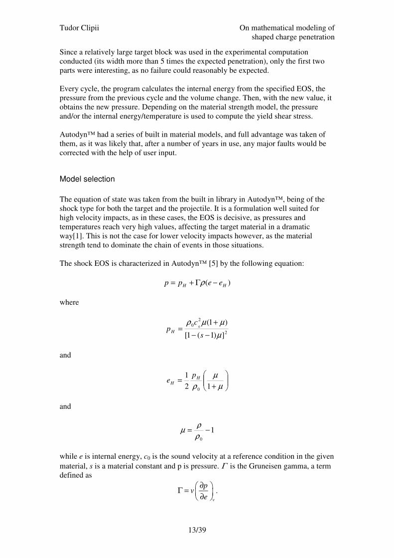
The shock EOS is characterized in Autodyn™ [5] by the following equation:
)( HH eepp −Γ+= ρ
where
2
2
0
])1(1[
)1(0
µ
µµρ
−−
+=
s
cpH
and
+=
µ
µ
ρ 12
1
0
H
H
pe
and
10
−=ρ
ρµ
while e is internal energy, c0 is the sound velocity at a reference condition in the given
material, s is a material constant and p is pressure. Γ is the Gruneisen gamma, a term
defined as
v
pv
e
∂ Γ =
∂ .

Tudor Clipii On mathematical modeling of
shaped charge penetration
14/39
However, Γρ is assumed to be constant. It should be noted that the denominator of the
pH expression limits the validity of the system. If (s-1)µ becomes 1, the expression
will go to infinity. However, s is chosen in such manner as to not have this occurrence
until the density (calculated from the known mass and volume of material in a cell)
becomes extremely high, something which makes the assumption that Γρ is constant
invalid anyway. For further details, the reader is directed to [5].
After much thought had been given to the question, the Zerilli-Armstrong model was
selected as the most suitable one for OFHC copper, being quite close to the set of
requirements stated previously. It is a model specifically developed for use in SC
calculations, whose development was sparked by the poor consistency obtained for
copper at very high flow rates with the Johnson-Cook model. Unfortunately, this
meant that the only material parameters widely spread for this model are the ones for
OFHC copper and Armco iron (another material poorly described by Johnson-Cook).
This model defines yield shear stress Y as:
εε &log
2043 ⋅⋅+⋅−⋅⋅+= TCTC
eCYY
where
ε is effective plastic strain
ε& is normalized effective plastic strain rate
T is temperature in degrees Kelvin
and Y0, C2, C3 and C4 are material constants defined by the user.
For the steel block modelled, the Steinberg-Guinan model [5] was initially used. The
parameters used described the behavior of 4340 steel, a rather common steel type in
such contexts. The material parameters from the built-in material library of
Autodyn™ were used, after being checked against a data leaf from an older
simulation engine (Pisces™), and found to be in agreement[6].
Unfortunately, it was established from the first runs that something was wrong with
the implementation of this model in Autodyn. The internal energy of the impacted
target reached extremely high and unrealistic values (resulting in temperatures in
excess of several thousand degrees), obviously not matching the energy input (in form
of the kinetic energy of the SC jet). However, Autodyn™ did not flag an energy sum
discrepancy (the program is supposed to check the energy balance every cycle). Thus,
the author assumes that a bug exists in the code as the model itself is theoretically
well founded and should work without problems. It should be noted that this
assumption has not been checked with Century Dynamics and should only be viewed
as an assumption.
After this initial setback, another model was selected, namely the common Johnson-
Cook (J-C) model. This model is widely used in hydrocodes as it combines reliability
with availability of material data for a wide range of materials. Its main drawback is,
however, a somewhat unphysical theoretical base, as it is a highly empirical model.
The Johnson-Cook model is well suited to this particular type of problem, as it takes
into account strain, rate of strain and temperature effects, all of which reach high
values in high velocity impacts. According to this model, the maximum shear stress a
given material can support at a certain time is expressed by:

Tudor Clipii On mathematical modeling of
shaped charge penetration
15/39
( )( )( )m
Hp
n
p TCBAY −++= 1log1 εε &
where
εpn is the normalized strain,
pε& is the normalized strain rate,
and roommelt
room
HTT
TTT
−
−= . The last term ensures that a completely molten metal will
have Y=0. A, B, C, n and m are material constants found in the built-in material
library.
The ε&log term needs a little explanation. As a logarithm, it tends to go to negative
infinity, as the strain rate approaches zero. This is, of course, not a representation of
realistic material behavior, so the Johnson-Cook model will set C to 0 if the strain rate
drops below a certain minimum (usually 1 s-1
). Unfortunately, this means the
expression above cannot be smoothly differentiated. Differentiating Y is of crucial
importance for establishing the direction of failure. Thus, it can be concluded that the
J-C model has one serious physical flaw in its strain rate dependency modeling.
Tudor Clipii On mathematical modeling of
shaped charge penetration
16/39
Geometric setup
One of the most crucial stages in setting up a hydrocode simulation is defining the
geometry of the problem. This involves defining the symmetry planes, the initial
shape of the interacting parts and initial conditions for the energy (be it kinetic,
chemical or thermal energy) as well as any boundary conditions.
Symmetry
In the 2D version of Autodyn™ that was used for this experiment, two different
symmetry settings were possible: planar and axial.
Planar symmetry means that the 2 dimensional shape drawn on the screen is assumed
to have thickness 1, thus making it possible to compute the volume. It is relatively
easy to realize that this symmetry assumption is not very well suited for projectile-
target representations, as projectiles are mostly long cylinders, something impossible
to model in planar symmetry.
Axial symmetry means that the volume of each element is obtained by rotating the on-
screen two-dimensional representation about the x-axis. It is thus possible to represent
cylinders of different shapes and non-constant radii. This type of symmetry is well
suited for ballistic simulations and was therefore used.
Shape
The simulated target used in the computations was a simple, cylindrical block of steel,
with radius of 75 mm and length of 150 mm. It was impacted along the axis of
revolution by the projectile described below. It was not constrained at any boundary.
The projectiles used were two cylindrical copper fragments, 4 mm long and 2 mm in
diameter. These were the dimensions found to be typical of a well developed SC-jet,
as illustrated in the X-ray photo of Appendix A. The speeds of the copper fragments
were 7800 m/s and 7500 m/s, also a reasonably realistic representation of typical SC
fragment speeds. The element starting closest to the target had the higher speed, in
agreement with the generally acknowledged fact that the speed of a SC jet decreases
from the tip towards the slug.
The distance between the two projectiles was the parameter varied in order to conduct
the investigation.

Tudor Clipii On mathematical modeling of
shaped charge penetration
17/39
Data interpretation
When an Autodyn™ computation is run, a very wide range of information is available
every cycle. A myriad of parameters from speed to density and strain are computed
and stored for each single cell. Of course, not everything can be saved for practical
reasons. The user has to choose a number of parameters to keep track of, and there are
a number of tools provided to do so.
The most complete solution is to save a cycle. This means that the entire computation
(every parameter for every cell) is saved, and can be reloaded at any time to analyze
any aspect of interest at that point in the computation. It is easy to understand that
such a saving takes some time to perform and takes a considerable amount of disk
space. Therefore, it is not very practical to use this method for every single parameter
investigation.
Another way of saving data during a computation is to instruct Autodyn™ to build a
graphical representation of a certain occurrence (at certain intervals, stated in time or
cycles) and then save it as an image. Later, the image can be viewed and several
images can be joined together in a film. This is a very useful feature as it displays
very well the changes the specific entity chosen goes through along simulated time.
Rendering these images is a very straightforward procedure and takes a relatively
magessmall amount of time, making it suitable to make quite a high number of such
images during one simulation run.
Both of the above methods were used. The first method, saving the whole problem,
had a secondary objective as well, in providing a restarting point should the program
crash irretrievably (an uncommon occurrence, but nevertheless present). Images were
taken frequently, typically at 15 cycle intervals.
Program termination
Autodyn™ will terminate a computation if instructed to do so after a given period of
time (alternatively number of cycles) or when it determines the energy balance is off
by a preset value (happens mostly when the movement of the materials has slowed
down very much, increasing the relative inaccuracy of the calculation
approximations). Every calculation run executed during this study was interrupted by
the time movement in the materials had diminished to insignificant values (1-2 m/s).
Post processor examination
After the program was terminated, the problem was saved in that state and then
analysis could be performed, to extract useful data.
First and foremost, the penetration achieved was measured. This requires some
defining, as Euler grids are not able to maintain clear boundaries between materials.
Thus, in the hole bottom there was a mixture of copper, steel and void. The
penetration was defined as the distance between the original outer boundary of the
target and the first cell in the hole bottom containing only steel. Typically, the
“mixed” cells were rather few (3 or 4) and considering the fact that they were around

Tudor Clipii On mathematical modeling of
shaped charge penetration
18/39
0.1 mm long each, we have negligible accuracy loss by the above definition. The
width of the hole was measured in a similar way.
After measuring the dimensions of the penetration, a number of credibility checks
were performed, as investigating the temperature and pressure distribution in order to
detect any glaring anomalies that may occur. This procedure was prompted by the
unsuccessful attempt to use the Steinberg-Guinan material model, when extreme (and
faulty) temperature ranges were achieved.
The main sources of information regarding the development of the penetration were
the pictures taken and saved by Autodyn™ at regular intervals. These were bundled
together and replayed as an animation of the penetration process.
Tudor Clipii
Computations
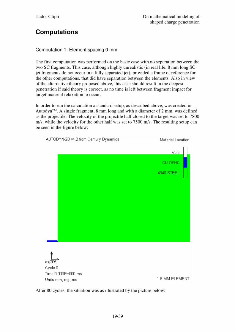
Computation 1: Element spacing 0 mm
The first computation was performed on the basic case with no separation between the
two SC fragments. This case, although highly unrealistic (in real life, 8 mm long SC
jet fragments do not occur in a fully separated jet), provided a frame of reference fo
the other computations, that did have separation between the elements. Also in view
of the alternative theory proposed above, this case should result in the deepest
penetration if said theory is correct, as no time is left between fragment impact for
target material relaxation to occur.
In order to run the calculation
Autodyn™. A single fragment, 8 mm long and with a diameter of 2 mm, was defined
as the projectile. The velocity of the projectile half c
m/s, while the velocity for the other half was set to 7500 m/s. The resulting setup can
be seen in the figure below:
After 80 cycles, the situation was as illustrated by the picture below:
On mathematical mod
shaped charge penetration
19/39
Computation 1: Element spacing 0 mm
The first computation was performed on the basic case with no separation between the
two SC fragments. This case, although highly unrealistic (in real life, 8 mm long SC
jet fragments do not occur in a fully separated jet), provided a frame of reference fo
the other computations, that did have separation between the elements. Also in view
of the alternative theory proposed above, this case should result in the deepest
penetration if said theory is correct, as no time is left between fragment impact for
get material relaxation to occur.
calculation a standard setup, as described above, was created in
Autodyn™. A single fragment, 8 mm long and with a diameter of 2 mm, was defined
as the projectile. The velocity of the projectile half closed to the target was set to 7800
m/s, while the velocity for the other half was set to 7500 m/s. The resulting setup can
be seen in the figure below:
After 80 cycles, the situation was as illustrated by the picture below:
On mathematical modeling of
shaped charge penetration
The first computation was performed on the basic case with no separation between the
two SC fragments. This case, although highly unrealistic (in real life, 8 mm long SC
jet fragments do not occur in a fully separated jet), provided a frame of reference for
the other computations, that did have separation between the elements. Also in view
of the alternative theory proposed above, this case should result in the deepest
penetration if said theory is correct, as no time is left between fragment impact for
a standard setup, as described above, was created in
Autodyn™. A single fragment, 8 mm long and with a diameter of 2 mm, was defined
losed to the target was set to 7800
m/s, while the velocity for the other half was set to 7500 m/s. The resulting setup can
Tudor Clipii On mathematical modeling of
shaped charge penetration
20/39
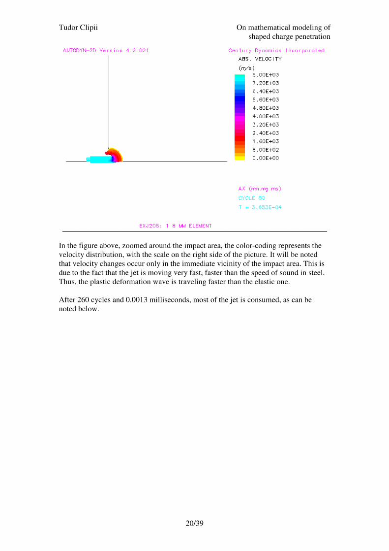
In the figure above, zoomed around the impact area, the color-coding represents the
velocity distribution, with the scale on the right side of the picture. It will be noted
that velocity changes occur only in the immediate vicinity of the impact area. This is
due to the fact that the jet is moving very fast, faster than the speed of sound in steel.
Thus, the plastic deformation wave is traveling faster than the elastic one.
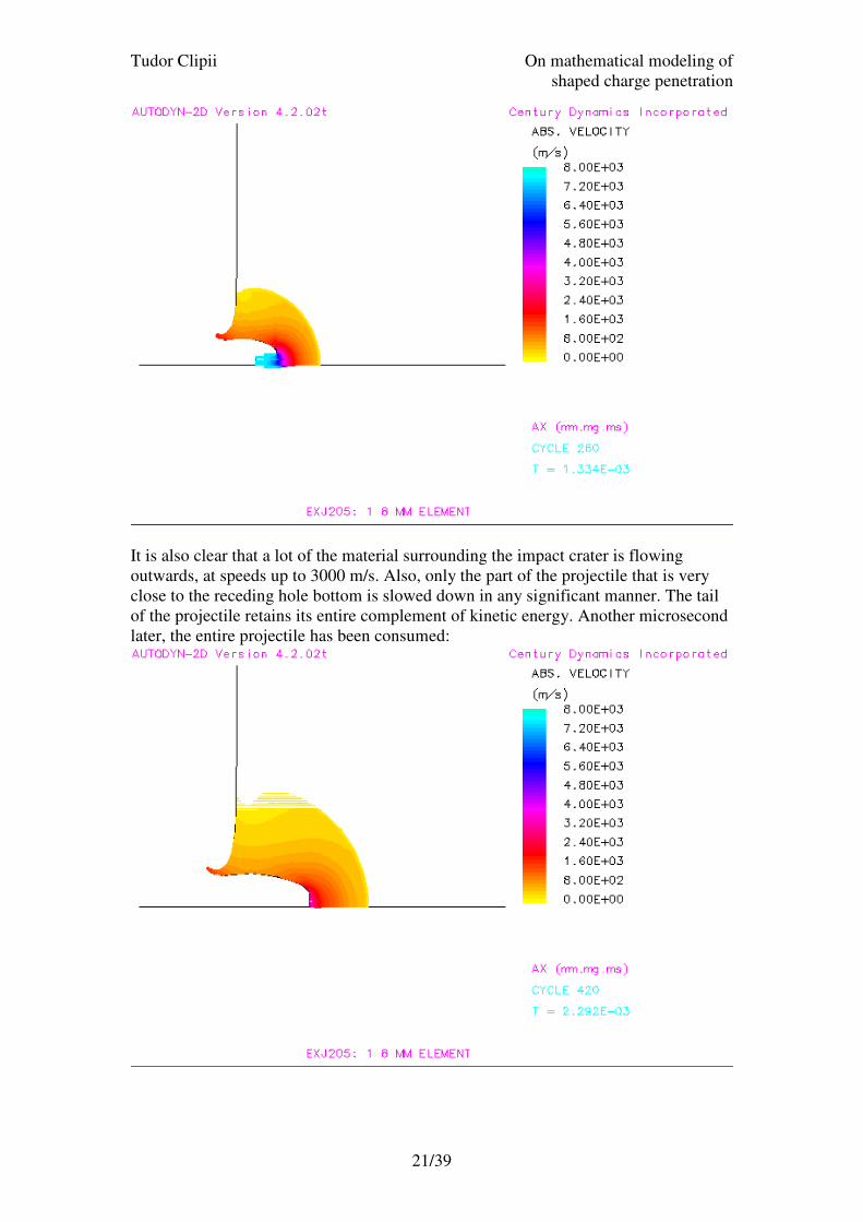
After 260 cycles and 0.0013 milliseconds, most of the jet is consumed, as can be
noted below.
Tudor Clipii On mathematical modeling of
shaped charge penetration
21/39
It is also clear that a lot of the material surrounding the impact crater is flowing
outwards, at speeds up to 3000 m/s. Also, only the part of the projectile that is very
close to the receding hole bottom is slowed down in any significant manner. The tail
of the projectile retains its entire complement of kinetic energy. Another microsecond
later, the entire projectile has been consumed:
Tudor Clipii On mathematical modeling of
shaped charge penetration
22/39
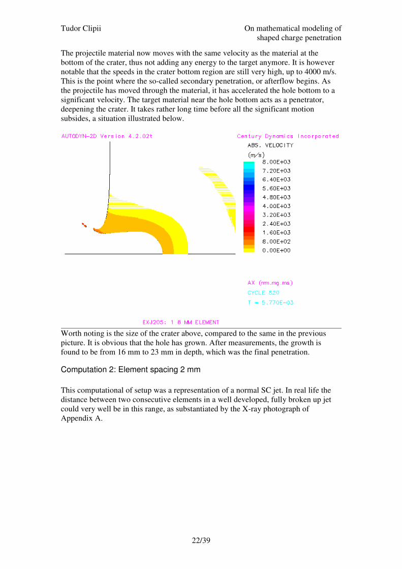
The projectile material now moves with the same velocity as the material at the
bottom of the crater, thus not adding any energy to the target anymore. It is however
notable that the speeds in the crater bottom region are still very high, up to 4000 m/s.
This is the point where the so-called secondary penetration, or afterflow begins. As
the projectile has moved through the material, it has accelerated the hole bottom to a
significant velocity. The target material near the hole bottom acts as a penetrator,
deepening the crater. It takes rather long time before all the significant motion
subsides, a situation illustrated below.
Worth noting is the size of the crater above, compared to the same in the previous
picture. It is obvious that the hole has grown. After measurements, the growth is
found to be from 16 mm to 23 mm in depth, which was the final penetration.
Computation 2: Element spacing 2 mm
This computational of setup was a representation of a normal SC jet. In real life the
distance between two consecutive elements in a well developed, fully broken up jet
could very well be in this range, as substantiated by the X-ray photograph of
Appendix A.
Tudor Clipii
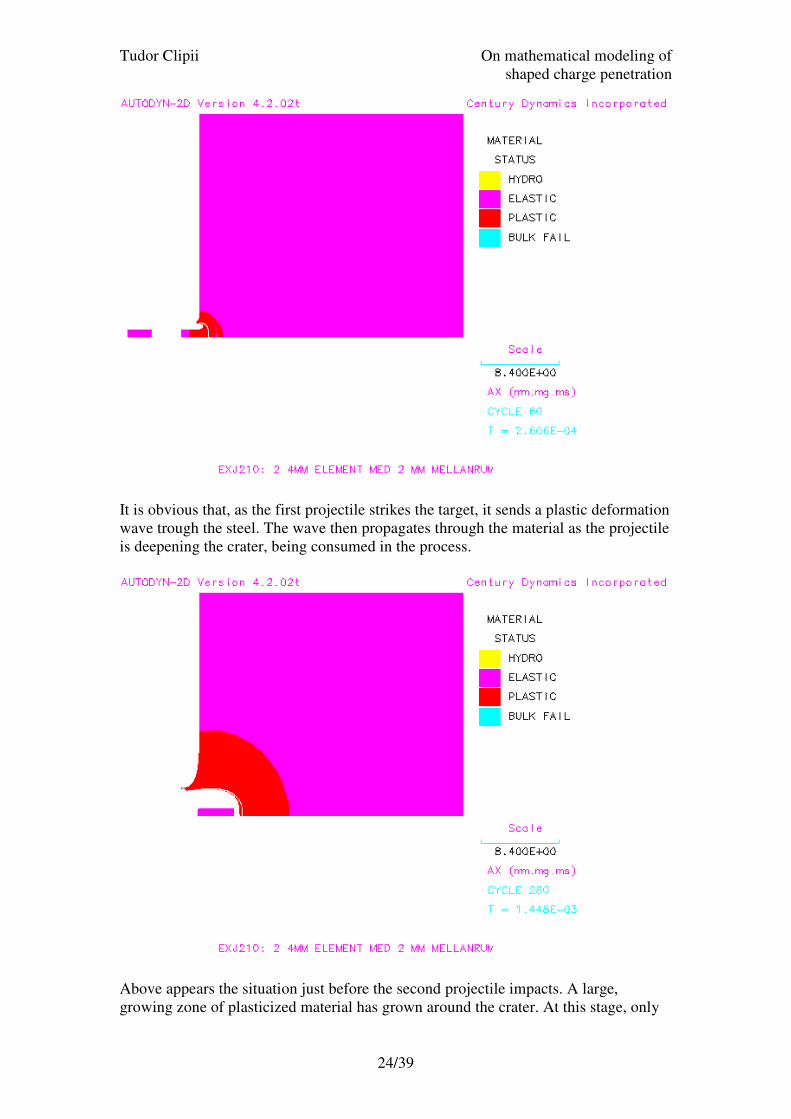
Below is representation of the situation as the first projectile is being expended into
the target. This time, material status is
can either be in plastic or elastic mode (hydro and bulk failure modes do not apply to
metals). This is determined by the loading of the material. If it exceeds the yield
limit, plastic deformation occurs.
On mathematical mod
shaped charge penetration
23/39
Below is representation of the situation as the first projectile is being expended into
the target. This time, material status is plotted instead of velocity fields. The material
can either be in plastic or elastic mode (hydro and bulk failure modes do not apply to
metals). This is determined by the loading of the material. If it exceeds the yield
limit, plastic deformation occurs.
On mathematical modeling of
shaped charge penetration
Below is representation of the situation as the first projectile is being expended into
plotted instead of velocity fields. The material
can either be in plastic or elastic mode (hydro and bulk failure modes do not apply to
metals). This is determined by the loading of the material. If it exceeds the yield
Tudor Clipii On mathematical modeling of
shaped charge penetration
24/39
It is obvious that, as the first projectile strikes the target, it sends a plastic deformation
wave trough the steel. The wave then propagates through the material as the projectile
is deepening the crater, being consumed in the process.
Above appears the situation just before the second projectile impacts. A large,
growing zone of plasticized material has grown around the crater. At this stage, only
Tudor Clipii On mathematical modeling of
shaped charge penetration
25/39
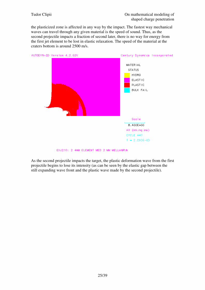
the plasticized zone is affected in any way by the impact. The fastest way mechanical
waves can travel through any given material is the speed of sound. Thus, as the
second projectile impacts a fraction of second later, there is no way for energy from
the first jet element to be lost in elastic relaxation. The speed of the material at the
craters bottom is around 2500 m/s.
As the second projectile impacts the target, the plastic deformation wave from the first
projectile begins to lose its intensity (as can be seen by the elastic gap between the
still expanding wave front and the plastic wave made by the second projectile).
Tudor Clipii On mathematical modeling of
shaped charge penetration
26/39
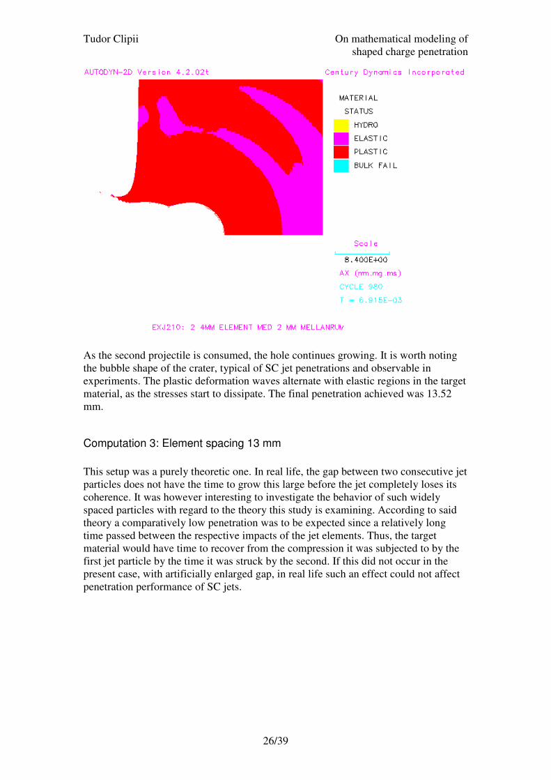
As the second projectile is consumed, the hole continues growing. It is worth noting
the bubble shape of the crater, typical of SC jet penetrations and observable in
experiments. The plastic deformation waves alternate with elastic regions in the target
material, as the stresses start to dissipate. The final penetration achieved was 13.52
mm.
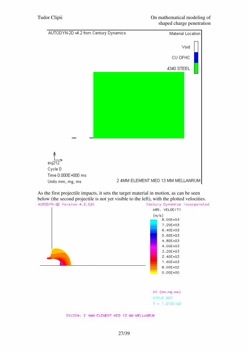
Computation 3: Element spacing 13 mm
This setup was a purely theoretic one. In real life, the gap between two consecutive jet
particles does not have the time to grow this large before the jet completely loses its
coherence. It was however interesting to investigate the behavior of such widely
spaced particles with regard to the theory this study is examining. According to said
theory a comparatively low penetration was to be expected since a relatively long
time passed between the respective impacts of the jet elements. Thus, the target
material would have time to recover from the compression it was subjected to by the
first jet particle by the time it was struck by the second. If this did not occur in the
present case, with artificially enlarged gap, in real life such an effect could not affect
penetration performance of SC jets.
Tudor Clipii
As the first projectile impacts, it sets the target material in motion, as can be seen
below (the second projectile is not yet visible to the left), with the plotted velocities.
On mathematical mod
shaped charge penetration
27/39
As the first projectile impacts, it sets the target material in motion, as can be seen
below (the second projectile is not yet visible to the left), with the plotted velocities.
On mathematical modeling of
shaped charge penetration
As the first projectile impacts, it sets the target material in motion, as can be seen
below (the second projectile is not yet visible to the left), with the plotted velocities.
Tudor Clipii On mathematical modeling of
shaped charge penetration
28/39
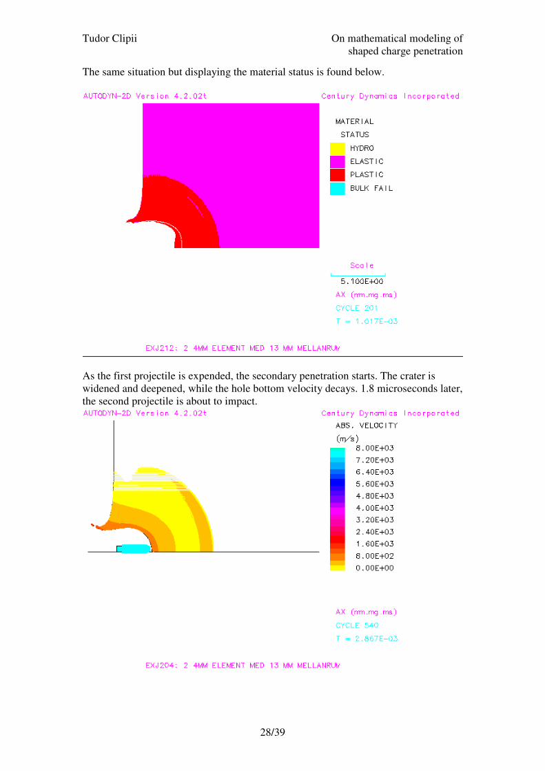
The same situation but displaying the material status is found below.
As the first projectile is expended, the secondary penetration starts. The crater is
widened and deepened, while the hole bottom velocity decays. 1.8 microseconds later,
the second projectile is about to impact.
Tudor Clipii On mathematical modeling of
shaped charge penetration
29/39
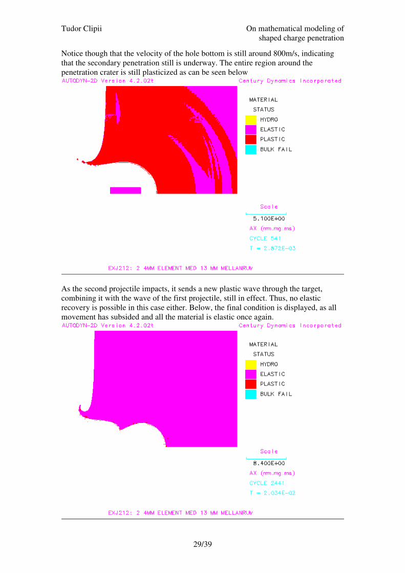
Notice though that the velocity of the hole bottom is still around 800m/s, indicating
that the secondary penetration still is underway. The entire region around the
penetration crater is still plasticized as can be seen below
As the second projectile impacts, it sends a new plastic wave through the target,
combining it with the wave of the first projectile, still in effect. Thus, no elastic
recovery is possible in this case either. Below, the final condition is displayed, as all
movement has subsided and all the material is elastic once again.

Tudor Clipii On mathematical modeling of
shaped charge penetration
30/39
Notice again the prominent bubble section of the crater, as well as the entrance lip,
both widely known phenomena in SC jet penetration, which suggest the computation
mimics natural response well. The final penetration was 15.6mm while the width of
the crater was 4.6mm.
Computations 4 and 5
Two more computations were conducted with this setup. As will be recalled from the
material strength modeling discussion, the J-C model had an unphysical
representation of the strain rate dependency. It was of certain interest to establish how
important this strain rate dependency was for the end result. Thus, the C constant was
manually set to 0 at all times and a computation was performed on a setup otherwise
identical to the one used for computation 3.
The result was so similar to the one obtained earlier that the pictures obtained are
interchangeable (actually, the material status illustrations from computation 3 are
really from computation 4, as the color palette of the originals were compromised due
to hardware problems). The resulting penetration was 15.20 mm deep and 4.9 mm
wide, thus somewhat shallower and wider that the one obtained with the original
material modeling.
Lastly, while it has been previously shown [1] that SC jets maintain a temperature
around 500 degrees in flight, these temperature values were not accounted for during
the computations made for this study. It was assumed that temperature does not have
a great influence on penetration depth, so the initial temperature specified was the
standard reference temperature in the material library, or 20 degrees Celsius (the
material constants are derived for this temperature).
It was desirable to investigate the influence of such factors, so a computation was
performed where the temperature of the SC jet was specified to be 700 degrees
Celsius. The resulting penetration was however similar to the ones obtained earlier,
thus the conclusion that jet temperature is not a factor of great importance. The craters
dimensions were 15.25 mm in depth and 4.9 mm in width. It should be noted that the
target model used was the modified J-C model from computation 4, with no strain rate
dependence.

Tudor Clipii On mathematical modeling of
shaped charge penetration
31/39
Conclusions
Result
From the computational results listed above, a number of conclusions could be drawn.
First, and most obvious, the penetration increased with growing gap between
consecutive jet particles. This effect was not expected according to the theory this
study is investigating. On the contrary, a diminishing penetration was the prediction
of said model, as target material has more time to recover from the compression it is
subjected to as the first projectile impacts.
As this does not seem to be the case, an explanation was required to somehow account
for the discrepancy between the proposed model and computational experiment. In the
following text, such an explanation will be proposed.
First, it was observed that, by the time the second impact took place, the movement of
the material in the hole bottom caused by the first projectile was not by any means
over. The material continued to move rather fast, even in case 3, with 13 mm of
spacing between projectiles, where the movement of the material was still around 800
m/s. It will be recalled that the suggested alternative theory was based on the
assumption that the target material is compressed after the first round strikes, storing
some of the energy of that projectile. This energy would then be lost if the target had
enough time to next impact for its material to recover from this compression.
However, the findings above clearly indicated that this was not the case. Instead, the
material was continually compressed by the moving mass around the hole area. The
continuous pressure does not allow for a relaxation of the compressed material. Thus,
no greater amount of energy was lost in this way. It is rather clear to the writer that
the energy loss has another explanation.
In the literature of the field[7], a preeminent analytical model for jet penetration is the
so-called hydrodynamic theory. It is only applicable for penetrations involving very
high velocities. The impact of a SC jet is an ideal application for this theory, as it
involves the highest speeds encountered in impact mechanics.
This theory states that the crater created by a jet grows in depth with the velocity:
jt
VU
ρρ+=
1
Where V is the speed of the jet, ρt and ρj are the densities of the target respective the
jet. By using the respective values 7800, 7.83 and 8.93, U is found to be 4028 m/s.
Measurements during the experiments gave values around 3880 m/s. This is close
enough for such a simple model, so it was accepted that the velocity of the hole
growth was constant throughout the primary penetration. Thus, during the primary
penetration, the jet is consumed at a rate of
Tudor Clipii On mathematical modeling of
shaped charge penetration
32/39
V – U =4000 m/s
This means the jet is able to penetrate
UUV
LP
j⋅
−=
where Lj is the length of the jet, after which it is expended. For a 4mm jet, moving
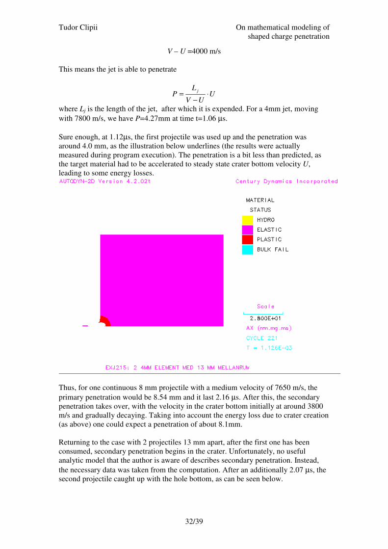
with 7800 m/s, we have P=4.27mm at time t=1.06 µs.
Sure enough, at 1.12µs, the first projectile was used up and the penetration was
around 4.0 mm, as the illustration below underlines (the results were actually
measured during program execution). The penetration is a bit less than predicted, as
the target material had to be accelerated to steady state crater bottom velocity U,
leading to some energy losses.
Thus, for one continuous 8 mm projectile with a medium velocity of 7650 m/s, the
primary penetration would be 8.54 mm and it last 2.16 µs. After this, the secondary
penetration takes over, with the velocity in the crater bottom initially at around 3800
m/s and gradually decaying. Taking into account the energy loss due to crater creation
(as above) one could expect a penetration of about 8.1mm.
Returning to the case with 2 projectiles 13 mm apart, after the first one has been
consumed, secondary penetration begins in the crater. Unfortunately, no useful
analytic model that the author is aware of describes secondary penetration. Instead,
the necessary data was taken from the computation. After an additionally 2.07 µs, the
second projectile caught up with the hole bottom, as can be seen below.

Tudor Clipii On mathematical modeling of
shaped charge penetration
33/39
During this time, the secondary penetration had deepened the crater to 6.7mm. Then,
a new penetration began, as the second projectile proceeded to dig into the crater
bottom. According to the hydrodynamic model above, the penetration was (using V =
7500 m/s) expected to be around 4.3 mm, and the projectile to be totally consumed
after 1.1 µs. Below is the slide taken by Autodyn™ at t = 4.30 µs, that is 1.11 µs later
than the previous picture.

Tudor Clipii On mathematical modeling of
shaped charge penetration
34/39
Although not readily visible in the picture, the second projectile is just used up. The
hole is now 10.9 mm deep, that is an increment of 4.2 mm from the time before the
impact. The predictions of the hydrodynamic model have been surprisingly accurate
so far.
However, the explanation for the deeper penetration of the fragmented jet, as
compared to the continuous one was now becoming clear. Assuming the same amount
of secondary penetration takes place after the second projectile is used up, this process
begins in a hole 8.1 mm deep for the continuous projectile and 10.9 mm for the
fragmented one. This should result in a final crater 2.8 mm deeper for the segmented
projectile. Still, as can be seen from the results above, the difference is only 1.88 mm,
thus, significantly lower. This must have something to do with the afterflow effect.
The hole from the single projectile was wider, so the explanation might lie in the fact
that a larger mass (the hole bottom being larger) moving during the secondary
penetration, in effect acting as a larger projectile. However, this is admittedly pure
speculation from the part of the author and further investigation is needed.
Further research topics - suggestions
During the preparatory work for this investigation, it quickly became clear that within
the limited time span available for the completion of the present thesis, a large
number of interesting questions would have to stay unanswered. In order not to let all
these by-products of the present work be lost in a non-constructive fashion, a number
of suggested topics for further research were compiled. Note that these are listed in no
particular order, so no assumption is made as to the feasibility or usefulness of the
studies.
Extreme inter-particle spacing
As is obvious from the above, the largest distance between jet particles that was used
for a simulation during this assignment was 13 millimeter. This is a very large
distance, considering that, with real SC’s, the distance between two consecutive
particles near the tip of the jet does not exceed the length of the particles themselves
(in this case 4 mm). However, as has been shown, when the second jet segment strikes
the hole bottom, the target material around the area of impact is still in motion from
the impact of the first jet fragment (the secondary penetration is still under way).
It would be very interesting to investigate the effect of gradually increasing the
spacing between the two fragments to and beyond the point where, by the time of the
second impact, material motion caused by the first one would have ceased. It would
be quite enlightening to obtain the optimum fragment spacing for maximum
penetration, as it would be very helpful for developing an understanding of the
secondary penetration phenomenon and its influence on subsequently impacting
projectiles.
In the author’s opinion, two cases might occur:

Tudor Clipii On mathematical modeling of
shaped charge penetration
35/39
1. The optimum penetration occurs when the second impact takes place at (or very
close to) the instant that the secondary penetration from the first projectile is
concluded. The material around the area of impact would still be compressed and
the energy of the first fragment would have been completely used up and
transformed into heat, aside from the part still stored in the compression of the
target material.
2. The greatest penetration occurs at some point well before the secondary
penetration of the first projectile comes to an end. In this case, energy from the
first projectile is partly stored in the material compression and partly in the
material motion, while the rest has transformed into deformation-generated heat.
If the first case were true, it would suggest that a large part of the penetration energy
might be expended compressing the material. The second case suggests that most of
the energy goes into accelerating the target material.
Multiple projectile jet
During the computations made for this study, a question arose regarding the exact
amount of influence the fragment number has on the final penetration. Thus, a trial
run was set up, with 8 1mm elements (2 mm in diameter). Four of these were initially
moving at 7500 m/s and the other four at 7800 m/s. Thus, the total mass and energy
were similar to the main experiment series that only considered two projectiles.
The resulting penetration from this experiment was quite interesting. The penetration
achieved 16.9 mm, more than 1 full millimeter deeper that what the main experiment
indicated. This is an indication that penetration increases with the number of
projectiles.
Such results have certain support in existing theory [7], which specifies that, given a
similar mass and velocity, a division of a continuous rod into several pieces separated
by small spaces would in effect extend the rod to a greater length since energy is
added during a longer time period, the time it takes the elements to travel the gaps in
the jet.
It would be interesting to investigate how much the penetration can be increased by
dividing the jet into ever-smaller fragments (even into the infinitesimal range). Also,
varying the spacing between consecutive particles might result in interesting values,
which in turn might spark new theoretical explanations.
Entire SC jet
So far, due to existing time constraints, only segments of SC jets have been
investigated. There is, however no real reason to refrain from modeling an entire SC
jet. The calculation would be extremely lengthy, but the results could be directly
compared to existing experimental data.

Tudor Clipii On mathematical modeling of
shaped charge penetration
36/39
Such comparison would shed light on many issues, from material modeling to
investigating how bad fragment alignment (the classic explanation on reduction of
penetration beyond optimum standoff) affect penetration.
Material strength modeling results
The reader is reminded that one computation (nr 4) was performed to assess the
functionality of the J-C model without the strain rate dependent term. The results were
a lower penetration and a wider crater. This is pointing to a higher Y without the strain
rate. That conclusion was somewhat unexpected, as higher strain rate should only
result in higher Y, never lower. Could it be that, at low strain rates (below 1) the
logarithmic term results in diminishing yield stress? If that is the case, the results
without strain rate dependency should be more accurate.
It is thus the opinion of the author that further investigation is needed before any final
conclusion might be drawn. An exact mapping of Y is possible in Autodyn™, and this
capability should be used to reach a final conclusion regarding the usefulness of the
said troublesome term.

Tudor Clipii On mathematical modeling of
shaped charge penetration
37/39
References
1. Zukas, J. A. and Walters, W. P., Fundamentals of Shaped Charges. John
Wiley & Sons, New York, 1989
2. Carleone, J., Tactical Missile Warheads. Progress in Astronautics and
Aeronautics, Vol. 155, American Institute for Astronautics and Aeronautics,
1993
3. Wijk, A. G., A New Theoretical Explanation of the Penetration Reduction for
Shaped Charge Jets Beyond Optimum Stand-Off. FOI (as yet unpublished)
4. Wijk, A. G., A New Mathematical Relation for the Relation Between Stand-
Off and Penetration of Shaped Charge Jets. FOI (as yet unpublished)
5. Autodyn Theory Manual. Century Dynamics Inc., 2001
6. Trigg, M., Hancock S., Kavaler, P., Hancock, H., Pisces 2D Elk Users
Manual, Physics International Company, 1981
7. Zukas, J. A., High Velocity Impact Dynamics. John Wiley & Sons, New York,
1990
8. Chi, Pei ; Sidhu, Harbans S. ; Mortimer, Richard W., A study of the break-up
of shaped charge jets. Drexel institute of tech Philadephia, 1963
9. Chou, P.C and Carleone, J., The stability of Shaped Charge Jet Break-up
Time, Journal of Applied Physics, 1977
10. Doig, Alistair, Some metallurgical Aspects of Shaped Charge Liners, Journal
of Battlefield Technology, Vol. 1, No. 1, 1998
.