on lte security: closing the gap between standards and ... · pdf fileon lte security: closing...
TRANSCRIPT

On LTE Security: Closing the Gap
Between Standards and Implementation
A Thesis submitted to the Faculty of
Worcester Polytechnic Institute
In partial fulfillment for the requirements for the
Degree of Master of Science
by
Nicholas DeMarinis
APPROVED:
Prof. Alexander M. Wyglinski, [email protected]
Prof. Hugh C. Lauer, [email protected]
Prof. Craig A. Shue, [email protected]

Abstract
Modern cellular networks including LTE (Long Term Evolution) and the evolving LTE-
Advanced provide high-speed and high-capacity data services for mobile users. As we become
more reliant on wireless connectivity, the security of voice and data transmissions on the
network becomes increasingly important. While the LTE network standards provide strict
security guidelines, these requirements may not be completely followed when LTE networks
are deployed in practice. This project provides a method for improving the security of LTE
networks by 1) characterizing a gap between security requirements defined in the standards
and practical implementations, 2) designing a language to express the encoding formats
of one of LTE’s network-layer protocols, 3) developing a compiler to translate a protocol
description in our language into an implementation, and 4) providing recommendations on
lessons learned during development of the language and compiler to support development
of future protocols that employ formal representations. In this way, our work demonstrates
how a formal language can be utilized to represent a cellular network protocol and serves
as an example for further research on how adding formalism to network standards can help
ensure that the security goals defined in the standards can be upheld in an implementation.
i
Table of Contents
Abstract . . . . . . . . . . . . . . . . . . . . . . . . . . . . . . . . . . . . . . . . . . . i
Table of Contents . . . . . . . . . . . . . . . . . . . . . . . . . . . . . . . . . . . . . . ii
List of Figures . . . . . . . . . . . . . . . . . . . . . . . . . . . . . . . . . . . . . . . iv
List of Tables . . . . . . . . . . . . . . . . . . . . . . . . . . . . . . . . . . . . . . . . v
1 Introduction . . . . . . . . . . . . . . . . . . . . . . . . . . . . . . . . . . . . . . . 1
1.1 Motivation . . . . . . . . . . . . . . . . . . . . . . . . . . . . . . . . . . . . . 1
1.2 Research contributions . . . . . . . . . . . . . . . . . . . . . . . . . . . . . . 3
1.3 Thesis Structure . . . . . . . . . . . . . . . . . . . . . . . . . . . . . . . . . . 4
2 Background . . . . . . . . . . . . . . . . . . . . . . . . . . . . . . . . . . . . . . . . 5
2.1 Brief History of Cellular Networks . . . . . . . . . . . . . . . . . . . . . . . . 5
2.2 3GPP Standardization Process . . . . . . . . . . . . . . . . . . . . . . . . . . 7
2.3 Overview of Cellular Network Architectures . . . . . . . . . . . . . . . . . . 9
2.4 What are the security threats to a cellular network? . . . . . . . . . . . . . . 10
2.4.1 Early Security Goals: GSM Networks . . . . . . . . . . . . . . . . . . 10
2.4.2 External Threats: Malicious Base Stations . . . . . . . . . . . . . . . 11
2.4.3 Insider Threats: Compromised User Equipment . . . . . . . . . . . . 12
2.4.4 Compromised Base Stations . . . . . . . . . . . . . . . . . . . . . . . 13
2.5 Overview of LTE Architecture . . . . . . . . . . . . . . . . . . . . . . . . . . 16
2.5.1 Fundamental Components . . . . . . . . . . . . . . . . . . . . . . . . 16
2.5.2 Key Features . . . . . . . . . . . . . . . . . . . . . . . . . . . . . . . 17
2.6 Implementation-based Security Threats . . . . . . . . . . . . . . . . . . . . . 18
2.6.1 Case Studies: SMTP and TLS . . . . . . . . . . . . . . . . . . . . . . 20
2.6.2 Standards vs. Implementation: The Knowledge Gap . . . . . . . . . 21
2.7 Chapter Summary . . . . . . . . . . . . . . . . . . . . . . . . . . . . . . . . 23
3 Methods . . . . . . . . . . . . . . . . . . . . . . . . . . . . . . . . . . . . . . . . . 24
3.1 Objective 1: Identify a protocol . . . . . . . . . . . . . . . . . . . . . . . . . 24
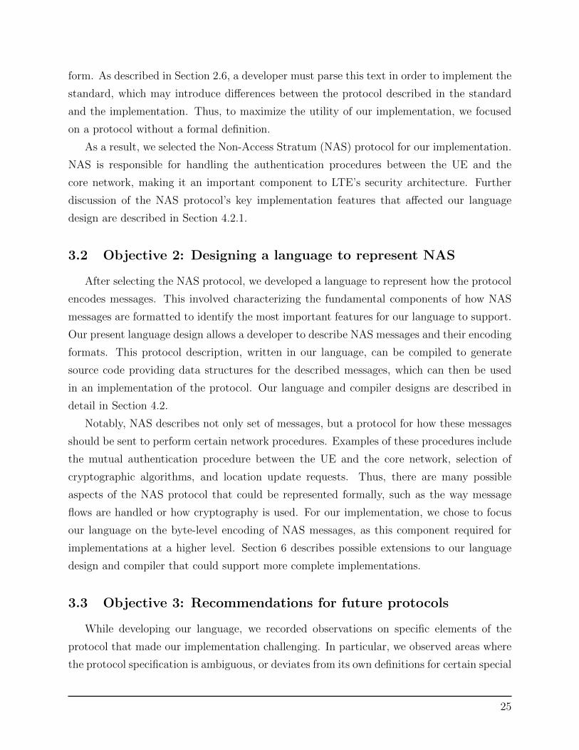
3.2 Objective 2: Designing a language to represent NAS . . . . . . . . . . . . . . 25
3.3 Objective 3: Recommendations for future protocols . . . . . . . . . . . . . . 25
4 Language design and implementation . . . . . . . . . . . . . . . . . . . . . . . . . . 27
4.1 Overview of NAS protocol . . . . . . . . . . . . . . . . . . . . . . . . . . . . 27
4.1.1 Message structure . . . . . . . . . . . . . . . . . . . . . . . . . . . . . 27
4.1.2 Encoding Formats . . . . . . . . . . . . . . . . . . . . . . . . . . . . 28
4.2 Language design . . . . . . . . . . . . . . . . . . . . . . . . . . . . . . . . . 30
ii

4.2.1 Key Features . . . . . . . . . . . . . . . . . . . . . . . . . . . . . . . 30
4.2.2 Packets . . . . . . . . . . . . . . . . . . . . . . . . . . . . . . . . . . 31
4.2.3 Types . . . . . . . . . . . . . . . . . . . . . . . . . . . . . . . . . . . 32
4.3 Compiler design and testing . . . . . . . . . . . . . . . . . . . . . . . . . . . 34
4.4 Chapter summary . . . . . . . . . . . . . . . . . . . . . . . . . . . . . . . . . 37
5 Recommendations on protocol designs . . . . . . . . . . . . . . . . . . . . . . . . . 38
5.1 Ambiguity in encoding descriptions . . . . . . . . . . . . . . . . . . . . . . . 38
5.2 Disparate standards documents . . . . . . . . . . . . . . . . . . . . . . . . . 39
5.3 Inheritance from other network standards . . . . . . . . . . . . . . . . . . . . 40
5.4 Chapter summary: Recommendations for reducing ambiguity . . . . . . . . . 40
6 Discussion and Future Work . . . . . . . . . . . . . . . . . . . . . . . . . . . . . . 42
6.1 Research contributions . . . . . . . . . . . . . . . . . . . . . . . . . . . . . . 42
6.2 Future work . . . . . . . . . . . . . . . . . . . . . . . . . . . . . . . . . . . . 42
6.3 Final discussion . . . . . . . . . . . . . . . . . . . . . . . . . . . . . . . . . . 43
References . . . . . . . . . . . . . . . . . . . . . . . . . . . . . . . . . . . . . . . . . . 44
Appendix A: Project source code . . . . . . . . . . . . . . . . . . . . . . . . . . . . . 48
iii

List of Figures
1 3GPP Project Coordination Groups . . . . . . . . . . . . . . . . . . . . . . . 8
2 Generic cellular network architecture . . . . . . . . . . . . . . . . . . . . . . 9
3 Example of macrocell and femtocell . . . . . . . . . . . . . . . . . . . . . . . 14
4 LTE logical architecture diagram . . . . . . . . . . . . . . . . . . . . . . . . 16
5 Conceptual map of distance between cellular network standards and physical
implementations. . . . . . . . . . . . . . . . . . . . . . . . . . . . . . . . . . 22
6 An example NAS message. . . . . . . . . . . . . . . . . . . . . . . . . . . . . 28
7 Example NAS message as specified in 3GPP standard TS 24.301. . . . . . . 29
8 An example packet encoding . . . . . . . . . . . . . . . . . . . . . . . . . . . 32
9 Compiler architecture . . . . . . . . . . . . . . . . . . . . . . . . . . . . . . . 35
10 Example generated class based on a packet definition . . . . . . . . . . . . . 36
11 Example decoding of generated Authentication Reject message . . . . . . . . 37
12 Listing of generated Attach Reject messages . . . . . . . . . . . . . . . . . . 37
13 Excerpt from TS 24.007 on usage of tags, or “Information Element Identifiers”
in network-layer messages. . . . . . . . . . . . . . . . . . . . . . . . . . . . . 39
iv

List of Tables
1 Comparison of 3GPP-family cellular network standards. . . . . . . . . . . . . 7
2 Example NAS messages. . . . . . . . . . . . . . . . . . . . . . . . . . . . . . 28
3 NAS message encoding formats . . . . . . . . . . . . . . . . . . . . . . . . . 30
v
1 Introduction
1.1 Motivation
Cellular networks provide vital communication services for an increasing number of users
around the world. According to the International Telecommunications Union (ITU), the
number of cellular network subscriptions has reached 7 billion in 2014 [1]. In developing
countries, the number of cellular network subscriptions per capita, or “penetration rate,” has
reached 90%, compared to 121% in developing countries, where many users have multiple
subscriptions. Thus, cellular networks are responsible for connecting these users together and
providing access to global resources like the Internet. To meet the increasing demand for
connectivity, wireless providers have developed new standards for allowing for higher network
capacity and faster data rates. The current leading standards for cellular communications
are LTE, or Long Term Evolution, and the evolving LTE-Advanced, which are developed by
the Third Generation Partnership Project (3GPP) to meet the design goals set by the ITU
for the fourth generation of wireless networks. LTE was designed to provide a significantly
more advanced network architecture than its predecessors, such that it can be extended as
cellular technologies evolve and as our population grows.
As we become more reliant on wireless connectivity, the security of cellular network
traffic becomes increasingly important. Early network generations like GSM (colloquially
known as “2G”) were designed to provide confidentiality against passive eavesdroppers and
to verify subscribers’ authenticity for billing purposes. However, it was discovered that this
threat model was too limited: GSM’s architecture was designed with the assumption that
all base stations were trusted devices. This allowed an outside attacker to set up a false (or
“rogue”) base station to accept users’ connections. Using such a device, an attacker could
send control messages to the connected devices to perform actions like disabling encryption
of traffic, forging messages, or denial-of-service (DoS) attacks against users connected to the
base station.
As later standards corrected GSM’s vulnerabilities, the threat model continued to evolve.
UMTS (known as “3G”), corrected the architectural vulnerability that made GSM vulner-
able to outside attackers by using stronger authentication mechanisms to prevent outside
devices from impersonating base stations. However, a more recent class of vulnerabilities
evokes a similar threat from inside the network. An increasing trend in cellular networks is
the deployment of small base stations to users in poor service or in areas of high network
congestion [2]. Notably, these devices, often called “femtocells,” are designed for deployment
1

in a user’s home or business, rather than the physically secure environment of a traditional
base station. This difference in physical security has enabled researchers to reverse-engineer
and compromise femtocell devices. Analyses conducted by DePerry et al. [3] and Borgaonkar
et al. [4] demonstrated various physical and remote attacks to gain root access on femtocell
devices using by exploiting relatively weak security measures. Once in control of the a fem-
tocell, the authors were able to intercept and forge certain traffic between connected devices
and the core network and hypothesized further attacks on the cellular network’s core to deny
availability or perform large-scale surveillance. Most critically, they demonstrated that these
devices are insecure by design, as network standards define base stations as trusted entities,
while commercial femtocell implementations are so easy to compromise with physical access.
Even though the 3GPP standards for femtocells require that devices should be physically
secure, this requirement does not hold in practice and thus undermines the security of the
network.
This exemplifies a knowledge gap between the organization creating the standards and
the developers that implement them. While the LTE standards developed by the 3GPP may
be designed to provide a more secure architecture, the software and hardware that implement
the standards may not implement them in such a way as to guarantee these properties. Thus,
a developer’s implementation of a protocol may deviate from the standards; for example,
1) the developer may take freedoms on parts of the standard that are not completely specified,
2) the developer’s interpretation of the specification may not match the standards body’s
interpretation, or 3) the developer may remove or add a feature (eg. a backdoor) that
differs from the standard. In a security-critical application, these differences may lead to
unintended vulnerabilities.
In this way, the attacks on femtocells described above raise questions on the security
practices in other cellular network hardware implementations, such as large-scale base sta-
tions or core network components. Since these devices are typically produced in a very
closed environment that includes many contracts and non-disclosure agreements, little open
research has been conducted to audit the security of cellular network hardware or how it is
configured and used in practice. Thus, how do we know that network operators are actually
following the 3GPP’s security standards? We discuss this in Section 2.6.1 by drawing on
widely-deployed Internet standards like email (SMTP) and Transport Layer Security (TLS)
as case studies. Since both of these standards have many possible security configurations
in practice, similar to LTE, we can infer that LTE networks face similar implementation
challenges.
2

LTE was designed to provide a new, robust architecture that can scale as cellular tech-
nologies evolve, but it also inherits the same security challenges as its predecessors. Notably,
LTE emphasizes network heterogeneity, or a reliance on various small base stations, which
research on the practical security of femtocells demonstrates is a serious security threat.
More critically, however, are the potential gaps between the standards and implementation—
similar to all network standards—that may compromise the network’s security despite its
robust design.
Therefore, our goal is to investigate a way to help close this gap between standards and
implementation to help ensure that the security goals intended in the standards are actually
implemented in practice. Some protocol standards attempt this by describing a protocol
using a formal language specification, which can then be used to generate an implemen-
tation that matches the standard. While this is true for some LTE specifications, certain
protocols do not include formal representations, which may make them particularly open to
implementation vulnerabilities.
1.2 Research contributions
In this project, we focus on just one protocol in LTE’s network standard, namely the Non-
Access Stratum (NAS) protocol, which is responsible for some of the components of LTE’s
authentication procedures. We develop a language for expressing the protocol’s encoding
based on the standard in order to demonstrate one example of closing the gap between its
specification in the standard and possible implementations. To facilitate this, we
1. Characterize the history of LTE’s security goals, related attacks, and how it led to the
LTE’s current requirements and threat model
2. Identify the NAS protocol as a specific point in LTE’s architecture that could introduce
vulnerabilities
3. Develop a language to express the NAS protocol’s encoding at a high level and translate
this representation into an encoding for its message formats, which represents one
example of connecting the 3GPP specification of the protocol with an implementation,
and
4. Provide recommendations based on lessons learned from creating the language on how
to develop future protocol designs that can be easily represented as a language
3

We hope that this work can help shape future protocol designs to help promote secure
implementations of network standards. We conclude with a discussion of future work to
extend the language to support more robust verification of implementations or as a starting
point for a testbed to identify potential protocol vulnerabilities.
1.3 Thesis Structure
The remainder of this document is organized as follows: Section 2 provides an overview
of security in cellular networks and discusses the gap between standards and specification.
Section 3 outlines our design goals and methods that led to the implementation of a language
to represent the NAS protocol. Section 4 provides an overview of the NAS protocol and
presents our language design which can represent it. Section 5 provides our recommendations
for future protocol designs to facilitate implementation as a language based on lessons learned
during our implementation. Finally, Section 6 summarizes our contributions and outlines
future work in using languages to improve security in LTE.
4

2 Background
This section outlines the challenges inherent to the design of cellular network architec-
tures that make them difficult to secure. In doing so, this section provides background on
the relevant history of cellular networks, and an overview of their major architectural com-
ponents. From there, we outline the major security goals of an LTE network and discuss
related work in identifying threats to cellular network architectures. Finally, we discuss the
difficulties in creating a verifiably secure network with respect to the standards and present
methods of dealing with this issue.
2.1 Brief History of Cellular Networks
Current cellular networks are the work of many decades of evolving wireless technologies.
These new technologies have been incorporated into standards released to help unify their
deployment across many network providers and countries around the world. Of the many
current standards, this section will discuss the family of standards that led to the develop-
ment of Long Term Evolution, as much of its architecture and security goals are inspired by
its predecessors.
One of the first modern standards for digital telephony was GSM, or the Global System
for Mobile Communications, was introduced in Europe in 1991 by the European Telecom-
munications Standards Institute (ETSI). The GSM standard intended to provide a unified,
global standard for mobile communications; it was designed to replace earlier mobile network
standards that used analog technologies, which were termed as the “first generation” of cel-
lular networks. In contrast, GSM described a standard for global voice communications and
represents the “second generation” of networks, popularly known as 2G. GSM was quickly
adopted throughout Europe and the world, reaching 100 million subscribers in almost 100
countries by 1998 [5]. Like traditional telephone systems and 1G networks, GSM was de-
signed for voice traffic; it utilized a circuit-switched network to route calls between devices.
In 2000, ETSI introduced the General Packet Radio Service (GPRS) to provide data services
for GSM networks. GPRS introduced a packet-switched network deployed alongside GSM’s
circuit-switched network to route data traffic to the public Internet. Initial deployments did
not provide much throughput, only reaching downlink speeds around 40Kbps due to the
need to compete with the circuit-switched voice traffic [6]. This was improved in 2002 with
the development of the third generation of mobile networks, or 3G.
5

The successor to GSM in this space was termed the Universal Mobile Telecommunications
System (UMTS), which built on GSM’s architecture but aimed to provide higher data rates
by using new frequency bands, encoding methods, and by emphasizing the importance of
data traffic on the network [7]. UMTS was developed by a group of representatives from
telecommunications companies in a number of countries called the 3GPP, or 3rd Generation
Partnership Project.
While UMTS met its goal of enhanced data rates, the wireless community saw the need
for a new architecture to allow for future expansion. Thus, the 3GPP developed Long Term
Evolution (LTE) was developed as part of the fourth generation of network architectures.
As its name suggests, a key goal behind LTE’s design was to provide an architecture that
could support future evolution of cellular technologies, like higher data rates and increased
capacity, while reducing the complexity of the network [8]. LTE uses an entirely packet-
switched architecture for both voice and data traffic in order to simplify the architecture
of its core network, called the Evolved Packet Core (EPC). To facilitate higher data rates,
LTE also uses more frequency bands and physical encoding schemes to increase its spectral
efficiency. This new architecture allowed for downlink speeds as high as 300Mbit/s and
uplink speeds up to 75Mbit/s, a notable improvement over previous standards.
While impressive, LTE is not marketed as a “4G network”, since it does not meet the
requirements defined for the term by the International Telecommunications Union (ITU),
which specifies a data rate of 1Gbit/s. To meet the requirements of a “true 4G” network,
the LTE standard was updated in 2011 under the name LTE-Advanced, which provides the
necessary physical layer changes to support the enhanced data rates [9].
A comparison of these various standards is shown in Table 1. Note that Table 1 and the
standards mentioned in this section represent only those most directly related to the evo-
lution of LTE. Other technologies common in the United States include the CDMA family
of networks, which derive from a “2G” standard based on Code Division Multiple Access
(CDMA). As technologies have evolved into the fourth generation of standards, LTE has
gained popularity over its competitors in other network families, making it the choice for
most carriers deploying “4G” technologies that previously used CDMA-based networks [8].
Examples of this in the United States include major carriers Verizon and Sprint, which pre-
viously relied on CDMA-based technologies, but are deploying LTE for their “4G” services.
Other US carriers including T-Mobile and AT&T provide wireless services using 3GPP-family
standards.
6

Table 1: Comparison of 3GPP-family cellular network standards.
Name Generation Networking type Peak data rate
Analog networks 1G Circuit-switched —
GSM 2G Circuit-switched —
GPRS 2.5G Packet-switched 56-114Kb/s
UMTS 3G Circuit and packet-switched 42Mb/s
LTE 4G LTE Packet-switched 300Mb/s
LTE-Advanced 4G Packet-switched 1Gb/s
2.2 3GPP Standardization Process
Any cellular networking standard describes a complex, distributed architecture that is
operated by many different carrier networks around the world. The process of developing
such a standard has many technical and regulatory challenges in order to balance the engi-
neering requirements of the network with practical and legal limitations. The standards for
GSM, UMTS, and LTE were developed and maintained by the 3GPP, an international orga-
nization made up of telecommunications corporations and national regulatory bodies. This
section briefly discusses the organization of the 3GPP and the process by which it develops
and maintains network standards.
Similar to the networks they create, the 3GPP has a complex organizational architecture.
At a high level, the 3GPP is composed of a series of Organizational Partners, or OPs,
which are groups of corporations and regulatory agencies in a specific country. Examples
of OPs include the European Telecommunications Standards Institute (ETSI) in Europe
and the Alliance for Telecommunications Industry Solutions (ATIS) in the United States.
OPs provide both technical expertise and input on the regulatory and security goals for its
specific country [10]. Each OP contains a number of member organizations—examples for
ATIS include corporations like Cisco, Sprint, Intel, Alcatel-Lucent, and regulatory bodies
like the Federal Communications Commission (FCC) and the Department of Commerce [11].
Members of these organizations are divided into Project Coordination Groups (PCGs)
and further divided into Technical Specification Groups (TSGs), which control specific stan-
dards documents on certain aspects of the network architecture. As an example, one PCG
manages the radio access network, or the specifications related to the network’s wireless
7

interfaces, and one specific TSG inside it manages the physical layer specifications. The
current makeup of PCGs and their corresponding TSGs is shown in Figure 1.
Figure 1: 3GPP Project Coordination Groups [10]
Each TSG has its own a set of elected officials, work items, and standards documents
for which it is responsible. Responsibilities for some specifications may be shared between
different groups [10]. Notably, only one group is dedicated to security aspects, which handles
architectural security requirements and develops the various encryption algorithms used
throughout the network.
To create a complete standard, the TSGs operate based on a larger “work plan” created
by the 3GPP as a whole, which provides milestones for releasing standards for deployment.
Since 2007, these milestones have included various “enhancements” to LTE, including LTE-
Advanced, which has contributed to the evolution of its architecture.
8

2.3 Overview of Cellular Network Architectures
While every cellular network standard has a different architecture, from a high level,
each type of network has the same set of fundamental components. The basic structure of a
cellular network is shown in Figure 2.
User Equipment
External Networks
User Equipment
Core Network
Base Station
Base Station
Base Station
Access Network
Figure 2: Generic cellular network architecture
The major components of such a network are:
• User Equipment (UE): These devices represent any mobile device controlled by a
user or customer on the network (mobile phone, tablet, modem, etc.), also known as
“end hosts”. By definition, UEs are mobile devices and can move to different points
on the network. In general, each UE contains a unique identifier so that they can
be individually recognized by the network. On 3GPP-family networks, the each UE
contains a Subscriber Identity Module (SIM) card that securely stores these identifiers.
• Base Stations (BS): Base Stations provide the wireless interface between the UE and
the core network. They are responsible for radio resource control, which entails main-
taining connections to each UE in its range and allocating wireless channel resources
accordingly. As UE move between different base stations on the network, base sta-
tions are responsible for communicating with the core to update each UE’s connection
information in a process called a handover.
• Access Network: The access network represents the subset of the network that
comprises the components responsible for communicating over the air interface, or
radio links between the base stations and user equipment.
9

• Core network: The core network is the subset of the network responsible for managing
devices and routing information across the network. The core network often differenti-
ates between control-plane and user-plane traffic. Control-plane, or signalling, traffic
refers to the necessary protocols and messages for keeping track of devices, such as at-
taching new devices to a base station, managing handovers, or allocating IP addresses
for data connections. User-plane traffic refers to traffic users’ voice and data traffic,
which must be routed to other UE on the carrier’s network, or to an external gateway
to access another network like the Internet, other carriers’ wireless networks, or the
Public Switched Telephone Network (PSTN).
These major components are provided by different implementations in each network
standard, but with the same major roles. Section 2.5 describes these components in further
detail for an LTE network.
2.4 What are the security threats to a cellular network?
As cellular network technologies have evolved, so have their security requirements and
guarantees. This section outlines the security threats faced by cellular networks as a whole in
order to describe the security goals that affect LTE networks. Here, we discuss the relevant
history of the security goals in cellular networks to establish a basis for LTE’s security goals
and architecture.
2.4.1 Early Security Goals: GSM Networks
In early cellular networks like GSM, the term “security” involved two design goals: confi-
dentiality against unauthorized eavesdropping, and authenticating users on the network for
billing purposes. In early telephone systems, skilled users developed methods for accessing
certain network features, such as long-distance calling, by reverse engineering the network’s
routing protocols to subvert the fees associated with these features. This process, known
as “phone phreaking” [12], was possible because these networks provided no method for
authenticating subscribers, and instead relied on the obscurity and relative secrecy of the
routing protocol to enforce fees.
GSM was designed with the goal of identifying authorized devices when they attach
to the network [13]. Each GSM UE contains a SIM card, a trusted device that stores
an identifier unique to each subscriber called the International Mobile Subscriber Identity
(IMSI) and a pre-shared key, called K or Ki. When a UE attaches to the network, the UE
10

can be authenticated using a simple challenge-response protocol using a random challenge
sent from the core network and K as a shared secret. Once a device is authenticated, the core
network can create a session for the device to track its actions for billing and call routing.
Another important concern for GSM was the confidentiality of users’ voice traffic. Since
a wireless channel is inherently a broadcast medium, the designers added support for encryp-
tion at the physical layer to prevent traffic interception by an unauthorized third-party [14].
Thus, the initial standard allowed for encryption, which is called ciphering in 3GPP stan-
dards, using one of two algorithms named A5/1 and A5/2, which were stream ciphers de-
signed specifically for GSM to provide confidentiality at a very low implementation cost.
These ciphers used a pre-shared key derived from K [15]. The designs for these ciphers
were initially kept secret to prevent outside cryptanalysis, but they were eventually reverse-
engineered and subsequently broken [16]. Modern GSM networks use a new cipher named
AS/3, which is stronger than its predecessors and is also used in UMTS networks. Newer
3GPP standards on GSM and GPRS discourage the use of AS/1 and AS/2, though both are
still deployed in practice.
This type of security architecture shows that GSM was designed to protect against ex-
ternal threats: unauthorized devices without a valid IMSI for the network, and external
eavesdroppers.
2.4.2 External Threats: Malicious Base Stations
After GSM was released, this security model was challenged by a new external threat:
unauthorized base stations. While the GSM standard authenticates user equipment, it does
not provide any means of authenticating the network itself. Thus, a GSM UE has no way to
determine if the base station to which it is connecting actually belongs to a legitimate carrier
network. This allows for the deployment of malicious or “rogue” base stations, which can
accept connections from legitimate UEs. This was first demonstrated by Mulliner et al. in
2009 [17] and since replicated and simplified by many researchers.
Using such an attack, a rogue base station masquerading as the core network can intercept
a handset’s communications or spoof calls and SMS messages. Furthermore, since the GSM
standard allows the the base station to determine which encryption modes are used for
transmission, a rogue base station can entirely disable ciphering using the null encryption
algorithm A5/0, leaving the device’s traffic visible in the clear. In this way, a rogue base
station takes advantage of GSM’s inherent lack of network authentication to eavesdrop on
11

all of a UE’s transmissions, or enable eavesdropping by a third party [17]. This influenced
the development of subsequent network standards such as UMTS.
Indeed, this technique is often used for the purposes of “lawful interception.” Law en-
forcement agencies can purchase devices that can be deployed in areas of interest that act as
cellular base stations and passively eavesdrop on users’ communications [18, 19, 20]. These
devices, which are often called IMSI catchers, can eavesdrop on the device’s IMSI numbers
allowing for further tracking of the users who own the devices.
To address GSM’s architectural vulnerabilities, UMTS was designed with a new threat
model that did not assume all base stations were trusted devices. To do this, UMTS utilizes
a new authentication procedure that provides mutual authentication of the user equipment
and the core network. In this procedure, the UE must prove its identity to the core network
and vice versa, allowing the UE to determine if it is connected to the legitimate carrier
network.
This process, termed Authentication and Key Agreement (AKA), entails an extended
procedure which occurs when a UE connects, or “attaches,” to the network. The AKA
procedure verifies the authenticity of both the UE and the core network using a series of
challenges based on pre-shared keys [21, 13].
Notably, while UMTS did address the critical architectural vulnerability that allows for
such easy deployment of rogue base stations, it does not completely eliminate the threat.
GSM remains widely deployed throughout the world alongside other networks. Thus, many
attacks are still feasible on newer networks by forcing devices to “downgrade” to GSM,
thereby denying the availability of other, more secure, networks in a given area [13].
2.4.3 Insider Threats: Compromised User Equipment
The security threats previously discussed involved attacks from malicious devices from
outside a network. Another notable class of attacks involve insider threats, or trusted devices
that may be compromised by an attacker.
One type of attack targets the “baseband processor” on UE devices, which is a special-
purpose processor inside every mobile phone that controls the phone’s radio interface. The
baseband processor is usually a separate processor core running a separate program from the
device’s application processor, which is typically the only processor accessible to the user.
Notably, the baseband processor may be considered a trusted device on the network, as the
network operator may not expect it to be accessed by a malicious party.
12

Attacks on the baseband processor have been performed locally on UE devices by gaining
root access [22] or exploiting memory corruptions like buffer overflows [23]. In addition,
attacks deployed from rogue base stations have been performed using messages sent via
Short Message Service (SMS, often simply known as “text” messages) [17, 24, 25], that have
allowed attackers to disrupt UE devices. Notably, the SMS standard allows transmission of
various control messages, including over-the-air configuration updates, in addition to text
messages. A rogue base station can masquerade as the core network to spoof an SMS
message—possibly with a malicious payload. Since UE on a GSM network have no means
of authenticating messages from the core network, the UE implicitly trusts these forged
messages and executes any control commands they may include. In this manner, SMS-based
attacks have been performed on GSM networks to crash applications, or change device
settings without the user’s intervention [17].
Extensions to these SMS-based attacks have been hypothesized on a larger scale, includ-
ing attacks involving cellular botnets, or groups of devices compromised by similar vulnera-
bilities [26]. Such a botnet could be used to perform Denial of Service (DoS) attacks on the
network core, denying availability to a portion of the network [27].
2.4.4 Compromised Base Stations
More critically, recent changes to cellular network architectures have made the threat
of rogue base stations more prevalent. As cellular traffic increases throughout the world,
networks are increasingly deploying small base stations in their service areas. A network
made up of many different types of such base stations is called a heterogeneous network.
While traditional base stations are typically large towers built in an area controlled by the
carrier, small cells, termed micro-, pico-, and femtocells, have a much more limited range, but
can be deployed in areas too small for a larger base station. An example femtocell is shown
compared to a traditional base station, or “macrocell,” in Figure 3. A typical femtocell has
a range of less than 100 meters, much smaller than a traditional base station, but is available
at a low manufacturing cost [2, 28]. This provides a cost-effective for a carrier to increase
its network’s capacity.
Network operators often deploy small cells to users in order to provide cellular service
in homes or small businesses in areas of high network congestion or poor service [31]. To
connect with the rest of the carrier’s network, femtocells and other small cells use an IP
network like the Internet as a backhaul, usually via a consumer Internet connection.
13

(a) A macrocell, or traditionalbase station. [29]
(b) A typical femtocell, a consumer de-vice about the size of a home Internetrouter. [30]
Figure 3: Example of macrocell and femtocell
The 3GPP standard TS33.320 provides security guidelines on femtocell devices [32]. Since
the devices connect to the cellular network from the Internet, an untrusted network, the stan-
dard includes requirements for authenticating femtocells and protecting the traffic between
them and the core network. For authentication, each femtocell must contain an authentica-
tion token or certificate, usually stored on a SIM card, which it uses to authenticate when
attaching to the network. Confidentiality and integrity are provided using IPSec, a protocol
layer that encrypts and authenticates packets at the network layer to provide end-to-end
security between two parties. In this case, the certificates are used to establish an IPSec
tunnel between the femtocell and the core network to protect sensitive core network traffic
from exposure over the public Internet. Notably, the standard also indicates that, similar to
traditional base stations, femtocells are “trusted environments,” in that they have a privi-
leged role in the network architecture and must remain secure from unauthorized tampering
with its hardware or software to avoid exposing this sensitive traffic.
From an architectural standpoint, femtocells serve the same role as a base station by
providing a radio interface for user equipment to the core network. However, femtocells
represent an important shift in the physical security of cellular base stations. Traditional base
stations are located in areas physically controlled by the network operator, while femtocells
are deployable anywhere and are not secure against physical tampering.
14
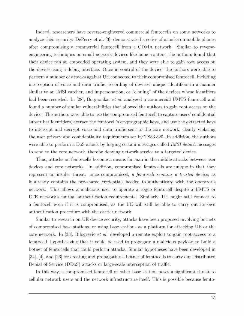
Indeed, researchers have reverse-engineered commercial femtocells on some networks to
analyze their security. DePerry et al. [3], demonstrated a series of attacks on mobile phones
after compromising a commercial femtocell from a CDMA network. Similar to reverse-
engineering techniques on small network devices like home routers, the authors found that
their device ran an embedded operating system, and they were able to gain root access on
the device using a debug interface. Once in control of the device, the authors were able to
perform a number of attacks against UE connected to their compromised femtocell, including
interception of voice and data traffic, recording of devices’ unique identifiers in a manner
similar to an IMSI catcher, and impersonation, or “cloning” of the devices whose identifiers
had been recorded. In [28], Borgaonkar et al. analyzed a commercial UMTS femtocell and
found a number of similar vulnerabilities that allowed the authors to gain root access on the
device. The authors were able to use the compromised femtocell to capture users’ confidential
subscriber identifiers, extract the femtocell’s cryptographic keys, and use the extracted keys
to intercept and decrypt voice and data traffic sent to the core network, clearly violating
the user privacy and confidentiality requirements set by TS33.320. In addition, the authors
were able to perform a DoS attack by forging certain messages called IMSI detach messages
to send to the core network, thereby denying network service to a targeted device.
Thus, attacks on femtocells become a means for man-in-the-middle attacks between user
devices and core networks. In addition, compromised femtocells are unique in that they
represent an insider threat: once compromised, a femtocell remains a trusted device, as
it already contains the pre-shared credentials needed to authenticate with the operator’s
network. This allows a malicious user to operate a rogue femtocell despite a UMTS or
LTE network’s mutual authentication requirements. Similarly, UE might still connect to
a femtocell even if it is compromised, as the UE will still be able to carry out its own
authentication procedure with the carrier network.
Similar to research on UE device security, attacks have been proposed involving botnets
of compromised base stations, or using base stations as a platform for attacking UE or the
core network. In [33], Bilogrevic et al. developed a remote exploit to gain root access to a
femtocell, hypothesizing that it could be used to propagate a malicious payload to build a
botnet of femtocells that could perform attacks. Similar hypotheses have been developed in
[34], [4], and [26] for creating and propagating a botnet of femtocells to carry out Distributed
Denial of Service (DDoS) attacks or large-scale interception of traffic.
In this way, a compromised femtocell or other base station poses a significant threat to
cellular network users and the network infrastructure itself. This is possible because femto-
15

UE Core Network
E-‐UTRAN(Radio Access Network)
External Networks
(IP, PSTN, Etc.)
HSSMME
S-‐GW P-‐GW
eNodeB
EPC(Evolved Packet Core)
Figure 4: LTE logical architectural diagram. Note that, like all cellular networks, an LTEnetwork is a large, distributed system—many instances of each component may exist on anetwork.
cells change the threat model for a cellular network: unlike previous network architecture,
the base station is no longer a trusted entity, but one that can be controlled by an attacker.
While the 3GPP provides requirements for the securely deploying femtocells, analyses con-
ducted in [4] and [35] have demonstrated that these requirements do not hold true in practice.
The 3GPP has acknowledged these threats in its own security standards, noting the possible
implications if their requirements are not guaranteed [32].
2.5 Overview of LTE Architecture
2.5.1 Fundamental Components
While the LTE architecture contains many new components, some components and much
of its terminology is inherited from earlier standards. The logical components of an LTE
network are shown in Figure 4.
As discussed in Section 2.3, LTE’s network is divided into two main components, the
radio access network and the core network. The access network is named E-UTRAN, or
Evolved UTRAN, which stands for UMTS Terrestrial Access Network, and incorporates all
of the radio interface components. The packet-switched core network, which is built on the
Internet Protocol (IP), is part of the System Architecture Evolution (SAE) standard and is
called the Evolved Packet Core (EPC). Together, the SAE and EPC standards are termed
16

the Evolved Packet System (EPS) [36]. These terms are often used interchangeably to refer
to the core network.
E-UTRAN, the access network, has the following components:
• User Equipment (UE): UE represent any devices that is under the control of a user,
as described in Section 2.3.
• Evolved NodeB (eNodeB): An eNodeB is a base station in an LTE network and is
an enhanced version of a UMTS base station, known as a NodeB.
The core network has the following components [36]:
• Home Subscriber Server (HSS): The HSS is a database that stores subscriber infor-
mation for the carrier’s network, including each UE’s unique identifiers and pre-shared
keys. The HSS is responsible for generating security keys for LTE’s authentication
procedures and maintaining state regarding the MME to which each UE is connected.
• Mobility Management Entity (MME): The MME is responsible for handling de-
vice authentication and creation of sessions that track a UE’s location throughout the
network, which are termed “bearer contexts.”
• PDN Gateway (P-GW): The Packet Data Network (PDN) gateway is responsible
for allocating IP addresses to each UE as well as maintaining quality of service (QoS).
• Serving Gateway (S-GW): The Serving Gateway provides the link between the
LTE network and external networks (eg. the Internet). The S-GW is responsible for
maintaining a “mobility anchor” for each UE to ensure packets are routed properly as
each UE moves about the network.
2.5.2 Key Features
LTE has a number of design elements that distinguish it from previous networks from
a security perspective. In addition to its improvements at the physical and link-layers that
enable higher data rates and channel capacities, LTE has a number of architectural differences
with respect to UMTS that make it interesting from a security perspective:
• Flat, IP-based architecture: LTE employs an entirely IP-based architecture, com-
pared to the fully or partially circuit-switched architecture present in previous stan-
dards. In addition, LTE is advertised as a “flat” architecture, meaning that it has
fewer specialized devices compared to previous networks.
17
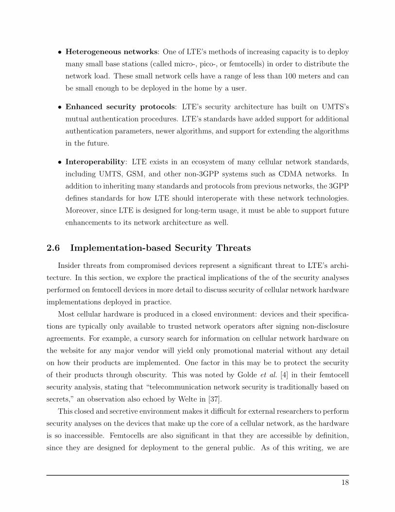
• Heterogeneous networks: One of LTE’s methods of increasing capacity is to deploy
many small base stations (called micro-, pico-, or femtocells) in order to distribute the
network load. These small network cells have a range of less than 100 meters and can
be small enough to be deployed in the home by a user.
• Enhanced security protocols: LTE’s security architecture has built on UMTS’s
mutual authentication procedures. LTE’s standards have added support for additional
authentication parameters, newer algorithms, and support for extending the algorithms
in the future.
• Interoperability: LTE exists in an ecosystem of many cellular network standards,
including UMTS, GSM, and other non-3GPP systems such as CDMA networks. In
addition to inheriting many standards and protocols from previous networks, the 3GPP
defines standards for how LTE should interoperate with these network technologies.
Moreover, since LTE is designed for long-term usage, it must be able to support future
enhancements to its network architecture as well.
2.6 Implementation-based Security Threats
Insider threats from compromised devices represent a significant threat to LTE’s archi-
tecture. In this section, we explore the practical implications of the of the security analyses
performed on femtocell devices in more detail to discuss security of cellular network hardware
implementations deployed in practice.
Most cellular hardware is produced in a closed environment: devices and their specifica-
tions are typically only available to trusted network operators after signing non-disclosure
agreements. For example, a cursory search for information on cellular network hardware on
the website for any major vendor will yield only promotional material without any detail
on how their products are implemented. One factor in this may be to protect the security
of their products through obscurity. This was noted by Golde et al. [4] in their femtocell
security analysis, stating that “telecommunication network security is traditionally based on
secrets,” an observation also echoed by Welte in [37].
This closed and secretive environment makes it difficult for external researchers to perform
security analyses on the devices that make up the core of a cellular network, as the hardware
is so inaccessible. Femtocells are also significant in that they are accessible by definition,
since they are designed for deployment to the general public. As of this writing, we are
18

unaware of any security audits in open literature performed on other components of modern
cellular network infrastructure.
In this way, research on femtocells provides unique insights into the security of production
hardware and how these hardware implementations may differ from the standards. Analyses
discussed in Sectionn 2.4.4 found poor security practices in commercially-available femtocell
devices—for example, open debug interfaces, unsigned firmware upgrade procedures, open
management interfaces for network services, and the use of unauthenticated control messages
from the core network. These provided vectors that enabled the authors to gain control of
the device, such as by uploading an altered firmware image.
This raises questions about the extent to which other core network hardware meets
the standards defined by the 3GPP to provide security. The vulnerabilities identified in
femtocells describe issues in the device’s configuration that violate the security 3GPP security
guidelines. But what if we extend this to consider vulnerabilities in the implementations for
the protocols used in the core network?
Consider, for example, LTE’s AKA procedure, which is used to authenticate devices
with the core network. The procedure mainly uses the Non-Access Stratum (NAS) protocol,
which is a binary message protocol defined between the UE and the MME (described further
in Section 4). The protocol has been well-studied, having been part of UMTS’s authenti-
cation procedure, and it has even been formally proven to guarantee mutual authentication
assuming that the required confidentiality and integrity properties are upheld [21]. When
evaluating the implementation, however, we may still need to consider the following ques-
tions:
• Does the protocol actually use integrity protection where specified? Does it verify
message authentication codes to reject invalid messages?
• Does the protocol accept messages from a UE before it has authenticated to the net-
work?
• Is encryption actually used where specified? Does the implementation use known weak
or deprecated encryption algorithms? How do we know?
• How are the packets in the protocol handled? Are they parsed in such a way to invite
exploits like buffer overflows that could cause the packet to be handled improperly?
These questions target the device’s implementation of the standard, rather than the
specification itself. While a given protocol implementation may operate successfully, just
19

like a femtocell may perform its role as a small base station, it may neglect certain security
requirements as defined by the standards. These make it insecure. We can find examples
of this by examining other widely-deployed protocols with security requirements that are
well-studied on the public Internet.
2.6.1 Case Studies: SMTP and TLS
Simple Mail Transport Protocol (SMTP), initially developed in the 1980s, is the de facto
standard for sending email messages. To deliver mail, the sender composes a message to
be sent from one mail server and accepted at the mail server of the intended recipient.
Since its introduction, the original standard (RFC 821 [38]) was developed, the protocol has
been extended to include richer message formats and many security measures to provide
confidentiality and integrity for messages during delivery and to authenticate the servers
responsible for sending mail. For example, the original protocol sent messages to other servers
in cleartext, allowing an eavesdropper to read the message. Since then, the standard has
been extended to support tunneling SMTP messages over Transport Layer Security (TLS)
to provide confidentiality and integrity protection when messages are transmitted. Notably,
TLS provides security for a point-to-point session—in this case, between mail servers or
between a client and their mail server, but TLS does not provide end-to-end security.
Just as many companies produce LTE network hardware, many different SMTP imple-
mentations exist, including open-source solutions like Postfix and sendmail, and commercial
closed-source implementations like Microsoft’s Exchange and IBM’s Lotus Notes. Again sim-
ilar to LTE’s architecture, there are many providers of email services to end-users, including
large Internet Service Providers to corporate networks.
Despite the many implementations and configurations of SMTP servers in the world,
SMTP is widely used in practice and is generally considered reliable. While SMTP can
reliably deliver mail, its support for security is not as dependable. Even though security
features like TLS have been standardized for many years and part of most SMTP server
implementations, it still not universally used in practice. In June of 2014, Google released a
dataset showing the proportion of email providers that used TLS for mail traffic with Google’s
servers [39]. When the data was released, only 50% of mail servers receiving outbound
traffic from Google supported TLS. Some of the organizations listed as not supporting TLS
were Internet Service Providers like Comcast and AOL. Since Google released the initial
dataset—which included the names of the providers not implementing TLS—the proportion
of providers using encryption has increased to 80%.
20

In this way, SMTP demonstrates a disparity between the standards, accepted best prac-
tice, and the various implementations of the protocol. Similar to SMTP, many LTE protocols
support optional cryptographic features like encryption or integrity protection. However, it
is unknown to what extent cellular network providers actually use these features or even
respect the cases where encryption is required by the standards.
TLS itself is a widely-used security protocol for providing confidentiality and integrity to
a number of applications, most notably web browsing and email. The initial standard was
released in 1995 as the Secure Sockets Layer (SSL) protocol and has been continually revised
to add new encryption algorithms for better security and address architectural vulnerabilities.
Thus, many versions of SSL and now TLS have been released and implemented by both clients
and servers for various applications that require security. Many implementations of TLS and
SSL exist in practice. Common examples include cryptographic libraries included with major
operating systems and browsers, such as OpenSSL in Linux, SChannel in Windows, and
SecureTransport in Mac OS X, as well as libraries built into major web browsers. In order
to maximize compatibility with older implementations, many of these implementations still
support outdated or deprecated versions of TLS, which has led to a number of widely-known
security vulnerabilities. As one example, a attack published in April 2014 named POODLE
exposed a vulnerability in many current versions of TLS by exploiting a mechanism that
allowed fallback to SSL version 3.0, an older variant of the standard with a longstanding
architectural vulnerability.
This demonstrates how practical usage of TLS differs from recommendations presented
in the network standards—even though security practices dictate the how a client or server
supporting TLS should be configured, a real-world implementation may use a different, less
secure configuration. Here, the challenge involves balancing the tradeoff of security vs. other
network requirements such as compatibility or performance.
This tradeoff exists in LTE as well and is readily apparent in the standards’ provisions
for allowing operators to define security policies on their network. However, the challenges
arises when reconciling these differing policies and implementations against the new need for
security against insider threats.
2.6.2 Standards vs. Implementation: The Knowledge Gap
Based on the previous security analyses of femtocell devices and observations of security
practices in other large systems, we can infer that the LTE core network is not without
implementation vulnerabilities. While the standards defined by the 3GPP may describe a
21

secure architecture, particular implementations may differ from the standard in ways that
do not adhere to the same security goals. This exemplifies a gap between the organization
creating the standards, the 3GPP, and the developers that implement them, as outlined in
Figure 5. In some cases, developers may take freedoms when implementing protocols that
are not clearly specified, or might misunderstand the specification.
Figure 5: Conceptual map of distance between cellular network standards and physicalimplementations. Note that the lines suggest possible mappings of hardware vendors tonetwork operators. The actual mappings are proprietary and not generally released.
This leads to disparity between the standard developed by the 3GPP and a hardware
vendor’s implementation, which could introduce vulnerabilities in a security-critical appli-
cation. Since LTE hardware is produced by an number of vendors, each may have different
interpretations of the standards. Further, network operators may introduce further differ-
ences in their specific configurations of LTE hardware. Since many security policy decisions
are left to network operators (a decision partly due to legal policies of different countries),
this step adds another level of disparity between the standards and the LTE service provided
to subscribers. Similar to SMTP and TLS, as described previously, these disparities may
lead to a wide array of implementations that function reliably, but may not meet LTE’s
security requirements.
In the cases of SMTP and TLS, disparities between current standards and best practices
were introduced as their respective standards evolved to include new security features. While
LTE is marketed as a new network architecture, it inherits many of the physical components
and their security challenges from previous networks. This may introduce some of the same
22

challenges as networks are deployed in practice. Moreover, LTE is designed to interoperate
with its predecessors GSM and UMTS, as well as other, non-3GPP networks, which may
provide additional areas for vulnerabilities.
These practical challenges exemplify how the disparity between the standards and phys-
ical implementations of LTE networks may pose a security threat. Thus, a key challenge
to ensuring LTE’s security involves identifying a way to reduce the potential for introduc-
ing implementations that may differ from the standards in such a way that could introduce
vulnerabilities.
2.7 Chapter Summary
This chapter has provided an overview of the major security challenges in cellular net-
works, focusing on how they have led to LTE’s security goals. Specifically, insider threats
represent an emerging challenge to cellular network security, as the threat of compromised
devices like femtocells allow an attacker access to the network’s core, which was once consid-
ered a trusted entity. As LTE networks continue to become more widespread, their reliance
on small cells makes this threat particularly concerning and calls into question the security
of the core network.
As a means of investigating this, we have identified a gap between the standards or-
ganization that provides LTE’s security goals and the developers involved in creating the
network. This provides an opportunity to introduce vulnerabilities that may compromise
the network’s security. Thus, in order to help ensure LTE’s security, we require a method
for more tightly connecting the standards that describe LTE’s protocols with physical im-
plementations. In this manner, we can help to eliminate ways in which differences may be
introduced into various implementations of LTE hardware to help ensure that the security
properties defined in the standards are maintained. In the next section, we describe our
process for identifying how to do this for one LTE protocol, as an example of one method to
help close this gap.
23

3 Methods
The overall goal of our implementation is to demonstrate one method of closing the gap
between LTE’s standards and the way they are implemented in practice. In doing so, we
hope that our work will serve as a starting point for further security research in LTE, as
well as provide recommendations for the development of future standards. In this project,
we select just one protocol in LTE’s network standard and develop a language to describe it,
providing one example for how a formal definition in a standard could aid the development
of a physical implementation. In order to do this, we the following objectives:
• Select one protocol in LTE’s network standards that exemplifies a gap between its
definition in the standards and practical implementations
• Devise a method for closing this gap—in our case, by developing a language to represent
it
• Using lessons learned from the development of the language, provide recommendations
on how future protocols could be designed to support expression as a language
The following sections describe our design process for carrying out these objectives.
3.1 Objective 1: Identify a protocol
LTE’s network-layer architecture is composed of a wide array of protocols with differing
responsibilities. Thus, we needed to select one such protocol as an example of the knowledge
gap that was relevant to LTE’s security and could benefit from a formal representation. To
provide an example related to the security challenges discussed in Section 2, we examined the
protocols involved in the authentication procedure between UEs and the core network. Since
traffic between UEs and the core is inherently routed through a base station, a vulnerability
in one of these protocols could be exploited by a compromised base station.
When examining the protocol stack between the UE and the core network, we also
desired to select a protocol complex enough to benefit from the formalism of a language.
Notably, some LTE protocols already provide formal definitions for certain components. For
example, the S1 protocol, which defines control and data-plane traffic for a number of LTE
devices, includes an ASN.1 definition to describe its message formats. This definition can
be compiled to generate a parser for S1 messages. However, not all LTE protocols provide
formal representations and are instead solely described by the standards documents in prose
24
form. As described in Section 2.6, a developer must parse this text in order to implement the
standard, which may introduce differences between the protocol described in the standard
and the implementation. Thus, to maximize the utility of our implementation, we focused
on a protocol without a formal definition.
As a result, we selected the Non-Access Stratum (NAS) protocol for our implementation.
NAS is responsible for handling the authentication procedures between the UE and the
core network, making it an important component to LTE’s security architecture. Further
discussion of the NAS protocol’s key implementation features that affected our language
design are described in Section 4.2.1.
3.2 Objective 2: Designing a language to represent NAS
After selecting the NAS protocol, we developed a language to represent how the protocol
encodes messages. This involved characterizing the fundamental components of how NAS
messages are formatted to identify the most important features for our language to support.
Our present language design allows a developer to describe NAS messages and their encoding
formats. This protocol description, written in our language, can be compiled to generate
source code providing data structures for the described messages, which can then be used
in an implementation of the protocol. Our language and compiler designs are described in
detail in Section 4.2.
Notably, NAS describes not only set of messages, but a protocol for how these messages
should be sent to perform certain network procedures. Examples of these procedures include
the mutual authentication procedure between the UE and the core network, selection of
cryptographic algorithms, and location update requests. Thus, there are many possible
aspects of the NAS protocol that could be represented formally, such as the way message
flows are handled or how cryptography is used. For our implementation, we chose to focus
our language on the byte-level encoding of NAS messages, as this component required for
implementations at a higher level. Section 6 describes possible extensions to our language
design and compiler that could support more complete implementations.
3.3 Objective 3: Recommendations for future protocols
While developing our language, we recorded observations on specific elements of the
protocol that made our implementation challenging. In particular, we observed areas where
the protocol specification is ambiguous, or deviates from its own definitions for certain special
25

cases. These observations have been compiled in Section 5 as recommendations for creating
future protocol designs that are more representable as a formal language. We hope that
these recommendations will help raise awareness of formal descriptions in designing message
formats, which could provide a method of resolving differences between specification and
implementation in these areas.
26

4 Language design and implementation
This section describes the design and implementation of our language and compiler to
represent encodings for the NAS protocol. We first provides an overview of the NAS protocol
in order to describe the key elements required in the language. We then describe the language
itself from a syntactic point of view to demonstrate how it can represent these components.
Finally, we present our initial design for a compiler that generates data structures for NAS
packet descriptions and discuss possible future extensions to our work.
4.1 Overview of NAS protocol
The Non-Access Stratum, or NAS, protocol is a control-plane protocol that supports
the “mobility” of user equipment on an LTE network, meaning it handles the addition,
removal, and tracking of UE devices on the network. Conceptually, NAS represents a logical
link between an LTE mobile device (UE) and the Mobility Management Entity (MME)
on the core network, which is responsible for keeping sessions for devices attached to the
network [40]. As discussed in Section 2, the NAS protocol provides the procedures for the
mutual authentication procedure between devices and the core network and the subsequent
derivation of cryptographic keys used for all further communications.
The NAS protocol is described in 3GPP standard TS 24.301 [40], which extensively
describes each procedure in the protocol and outlines the format of each message. All NAS
procedures are handled as a sequence of messages passed between a UE and the MME. Some
example messages and their roles are described in Table 2 [40].
Each message contains a number of fields, called information elements, which contain the
relevant message data to carry out the network procedure. The structure of these messages
and their encoding formats is described further in Section 4.1.2.
4.1.1 Message structure
Similar to many low-level protocols in other networks, NAS messages are encoded on a
byte level to reduce the size of messages. On the most basic level, each message contains a
header and a number of fields specific to the message.
A NAS header contains three fields to identify the protocol, the type of message, and
a security parameter, followed by the message fields, as shown in Figure 6. The security
parameter indicates if the message is encrypted or integrity protected; in these cases, a shim
27

Table 2: Example NAS messages.
Message Name Direction Description
Attach Request UE to MME Request addition to the network;starts authentication procedure andincludes a UE’s supported encryp-tion modes, etc.
Security Mode Command MME to UE Contains encryption algorithms andsecurity parameters selected by theMME
Authentication Request MME to UE Start of a challenge in the authenti-cation procedure
Tracking Area Update Request UE to MME Start of procedure to update trackingsession information
01234567
Header Type Protocol Type
Message Type
Field
Field
· · ·
Figure 6: An example NAS message.
header is prepended to the message containing the relevant data to decrypt or verify the
message.
4.1.2 Encoding Formats
While the headers for NAS messages are relatively straightforward, the fields that contain
the message payload are more complex. The specification provides a listing of the possible
fields that may be present in each message. An example is shown in Figure 7.
Each field has a presence specifier, indicating if the field must be included in the message
or is optional. Further, the listing also gives a size for each field. Some fields have a fixed
28

Figure 7: Example NAS message as specified in 3GPP standard TS 24.301. [40]
length in all packets of a given type, while the lengths of other fields may vary as specified
by a length tag.
To rectify these options, the standard provides various formats for encoding the different
types of fields. Optional fields are encoded by adding a unique value, called a “tag,” at the
start of the field. Fields with variable length are encoded by prepending the data field with
its length.
In the listing that specifies the fields for each message, each field is assigned a “format,”
which defines a method for encoding the field using these constructs. These encoding formats,
defined in another 3GPP standard [41], are named based on the data they include. The most
basic type, type V, only includes the message’s value with no extra information—this type
is used for mandatory fields. Other types include type TV, which includes a tag and is used
for optional fields. Similarly, type TLV is used for variable-length fields and includes a tag,
and a field length.
To complicate matters, different sizes of tags and lengths are used for certain types. The
standard defines two formats using length fields, one set with a single-byte length field, and
a set with a two-byte length field, which are named with the suffix “-E”, (eg, type TLV-E
is a TLV field with an extended length). Tags, which called Information Element Identifiers
(IEIs), are specified as either one byte, or four bits, depending on the field. These message
formats are summarized in Table 3.
This overview of the NAS protocol and its various message formats demonstrates the basic
components of a NAS message. Section 4.2 discusses how we identified a set of language
features based on the NAS protocol’s design to incorporate in our language.
29

Format Description Tag Length Length field size Value
T Tag only Yes No — No
V Value only No No — Yes
TV Tag and value Yes No — Yes
LV Length and value No Yes 1 byte Yes
TLV Tag, length, and value Yes Yes 1 byte Yes
LV-E Length and value No Yes 2 bytes Yes
TLV-E Tag, length, and value Yes Yes 2 bytes Yes
Table 3: NAS message encoding formats
4.2 Language design
In order to represent how the NAS protocol encodes messages, our language requires a way
to describe the data structures that comprise each packet defined in the protocol. This section
describes the design of our language. We first outline our language’s key requirements based
on the NAS specification and describe how they influenced the constructs in our language.
4.2.1 Key Features
At the most basic level, the NAS protocol describes a series of data structures based on a
defined format. Our design is based on this simple idea of specifying the elements in a data
structure, closely following how struct types are defined in the C programming language.
The target for our language was to use it to generate data structures that a developer
can use to access the various fields of a NAS packet while abstracting away the byte-level
encoding described in the standard. In this way, the language can help remove the challenge
of encoding the packet data structures into a byte stream as defined by the standard, thereby
removing the need for a developer to implement this step by hand. Our specific compiler
implementation was designed to generate a set of header files in C++ pertaining to the
packet data structures specified in the language. The goal of this was to provide an interface
that a developer could use to construct NAS packets for an implementation.
After examining the various formats in which NAS messages are specified, we identified
the following notable features of the NAS protocol to support in our language:
• Optional fields: Many fields in NAS packets are optional. These fields must be avail-
able in a data structure accessible to a programmer when building an implementation,
30

but do not appear in a transmitted packet unless they are utilized. This has the ob-
vious implication that the size and structure of a given packet may change based on
which fields are included, a significant difference from C structs. Thus, our language
must have the ability to specify mandatory and optional fields and encode only those
which are populated.
• Type formats: Every NAS message is specified with a type format that describes
how the message is encoded. Our language must have a way of expressing the rules
these types and encoding fields based on them.
• Half-byte fields: Many fields in NAS messages, including the header fields, use a size
of 4 bits to encode certain data in order to reduce message size. Notably, these fields
are used for enumerated types to represent elements like status codes.
Based on these requirements, we defined two fundamental constructs that define our
language: packets and types. Packets specify complete NAS messages, which contain a set
of fields. The definition of a packet specifies enough information to encode it into a stream
of bytes that comprise a valid NAS message. Types define the rules for encoding each field,
whether the field represents a simple data value encoded in a V type field, or a complex
structure in a TLV-E field.
While the overall goal of this project was to create a language implementing the NAS
protocol, an additional requirement of our design was to make our language definition generic
enough to specify other protocols that use constructs similar to the NAS protocol. This allows
our language design to extend to describing other protocol formats, allowing for possible
application to other protocols.
4.2.2 Packets
Packets represent a data structure that encodes a single NAS message. Conceptually,
the packet definition is very straightforward. Similar to a structure in the C programming
language, a packet is defined containing a set of ordered fields, as follows:
packet Alpha {
mandatory uint8 foo = 0xAB;
mandatory uint16 bar;
}
This example defines a packet named “Alpha” that contains two fields, foo and bar.
Each line specifying a field can contain four elements: a presence specifier, the field’s type,
31
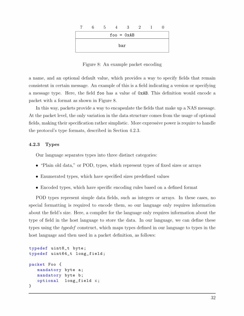
01234567
foo = 0xAB
bar
Figure 8: An example packet encoding
a name, and an optional default value, which provides a way to specify fields that remain
consistent in certain message. An example of this is a field indicating a version or specifying
a message type. Here, the field foo has a value of 0xAB. This definition would encode a
packet with a format as shown in Figure 8.
In this way, packets provide a way to encapsulate the fields that make up a NAS message.
At the packet level, the only variation in the data structure comes from the usage of optional
fields, making their specification rather simplistic. More expressive power is require to handle
the protocol’s type formats, described in Section 4.2.3.
4.2.3 Types
Our language separates types into three distinct categories:
• “Plain old data,” or POD, types, which represent types of fixed sizes or arrays
• Enumerated types, which have specified sizes predefined values
• Encoded types, which have specific encoding rules based on a defined format
POD types represent simple data fields, such as integers or arrays. In these cases, no
special formatting is required to encode them, so our language only requires information
about the field’s size. Here, a compiler for the language only requires information about the
type of field in the host language to store the data. In our language, we can define these
types using the typedef construct, which maps types defined in our language to types in the
host language and then used in a packet definition, as follows:
typedef uint8_t byte;
typedef uint64_t long_field;
packet Foo {
mandatory byte a;
mandatory byte b;
optional long_field c;
}
32

As in many other programming languages, enumerated types represent fields with a
specific set of values. Our language provides support for enumerated types with a parameter
to specify the size of the field they represent. Notably, our language’s support for enumerated
types allows for the specification of types smaller than one byte, to allow for the NAS
protocol’s use of these types for half-byte fields.
An enumerated type can be defined as follows:
enum Foo : 4 {
A = 0x1 ,
B = 0x2 ,
C = 0x4 ,
}
When compiled, the compiler is responsible for ensuring that these fields are included
with their specified sizes when encoded as a byte stream.
Encoded types require further expressiveness to describe a custom set of formats for
encoding at type. To provide a generic way of encoding all of the type formats defined in
the NAS standard, we describe an encoded type using two constructs: a structure definition
and an encoding definition. The structure definition defines how the data in the type is
formatted, similar to a packet or C struct. The encoding definition specifies how fields in
the structure are updated when the packet is encoded. In the NAS specification, this entails
filling the length field with the type’s size before encoding.
An encoded type is defined as in the following example, which describes a TLV type, as
defined in the NAS standard:
type TLV(tag , size) {
structure:
uint8 iei = tag;
uint8 length;
uint8 data[size];
encoding:
length = this_length;
}
As specified in Table 3, this type’s structure includes a single-byte tag field, a single-byte
length, and an array of bytes to represent the data portion, which allows for the variable-
length properties required of this type. The encoding portion of this type marks which field
should be populated with the size of the field at the time of encoding. The size of the field
is denoted by the keyword this length;
33

In addition, a type’s definition also allows for the specification of parameters to define a
specific instance of this type. Here, the parameters tag and size specify an the value of the
tag field and an initial size of the data field. These parameters are specified when a type is
used in a packet definition. The following example defines the NAS Authentication Failure
packet, which uses the TLV type and a number of enumerated types to represent the NAS
header:
packet AuthenticationFailure {
mandatory SecHeader headerType;
mandatory ProtoDescrim protoDescrim = EPS_MOBILITY_MANAGEMENT;
mandatory MsgType msgType = EPS_AUTH_FAILURE;
mandatory EmmCause cause;
optional TLV(0x30 , 16) authFailParam;
}
In this manner, we can define encoded types to represent all of the type formats defined
by the NAS standard in Table 3. As shown above, this allows us to specify the encodings
for the various field types used in NAS packets.
Section 6 describes future work for improving the expressiveness of our language.
4.3 Compiler design and testing
In order to develop an implementation based on a protocol specification defined in our
language, we developed a compiler to generate the described data structures.
For our implementation, we developed a compiler capable of generating these data struc-
tures as C++ header files. From there, we used the interface provided by these data struc-
tures to encode the packets and test them against an existing NAS protocol decoder.
Our compiler is designed to take a protocol defined in our language as an input and
generate a set of C++ header files for each packet and predefined type. We selected C++ as
a target language for code generation since it provided useful data structures for representing
packets while still providing the low-level operations necessary for working with a binary
protocol.
The compiler for our language follows a modular design, depicted in Figure 9. The major
components of the compiler are as follows:
• Lexer and Parser: These components are responsible for parsing the textual descrip-
tion of the protocol into tokens that can be recognized by the rest of the compiler. This
34

Figure 9: Compiler architecture
step is often known as the “front end” of the compiler. These components were gen-
erated by the open-source parser generator ANTLR [42]. ANTLR generates a parser
based on a formal grammar definition, which defines the language’s reserved words and
syntax.
• Abstract Syntax Tree (AST): Once parsed into a stream of tokens, the compiler
constructs a representation of the protocol described by the language in an Abstract
Syntax Tree. This data structure maintains a hierarchy of the various definitions in the
language, which can be parsed in order to perform operations like code generation. As
its name suggests, this provides a way of abstracting the language’s syntactic features
from the representation in the compiler.
• Symbol Table: A symbol table is a series of lookup tables that provide information
on the various elements defined in a language. In our compiler, a symbol is mainly
used to store information about each of the type definitions in the protocol to support
generation of the various packet data structures.
• Code Generation: This final step, known as the “back end,” parses the AST and
generates C++ header files for each packet in a given protocol definition. Thus, it uses
all of the information gathered in the previous parsing steps to generate a valid C++
header.
As with all modular compilers, this design allows for the development of different front-
ends and back-ends based on new requirements. For our language, this could mean developing
code generators for different languages, or allowing interoperability with verification tools like
model-finders. Further discussion of extensions to the compiler are described in Section 6.
The generated code for a protocol definition defines an interface that a developer can use
to build NAS packets. Taking advantage of C++’s object-oriented features, our compiler
35
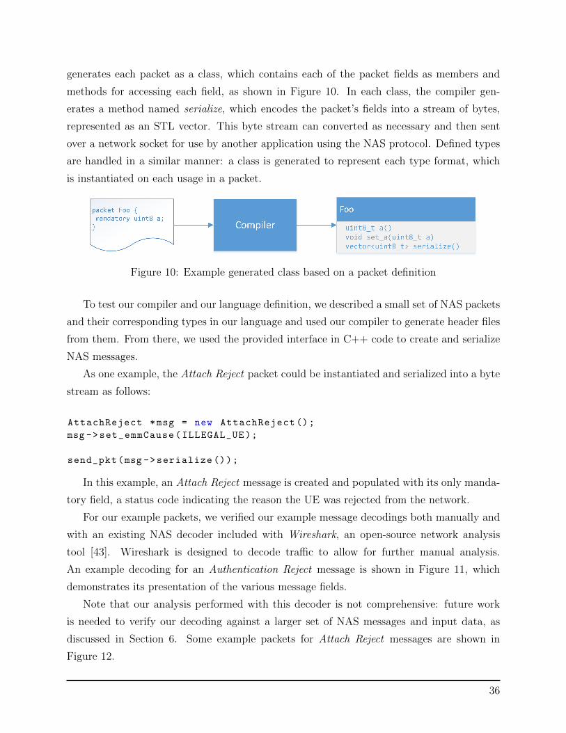
generates each packet as a class, which contains each of the packet fields as members and
methods for accessing each field, as shown in Figure 10. In each class, the compiler gen-
erates a method named serialize, which encodes the packet’s fields into a stream of bytes,
represented as an STL vector. This byte stream can converted as necessary and then sent
over a network socket for use by another application using the NAS protocol. Defined types
are handled in a similar manner: a class is generated to represent each type format, which
is instantiated on each usage in a packet.
Figure 10: Example generated class based on a packet definition
To test our compiler and our language definition, we described a small set of NAS packets
and their corresponding types in our language and used our compiler to generate header files
from them. From there, we used the provided interface in C++ code to create and serialize
NAS messages.
As one example, the Attach Reject packet could be instantiated and serialized into a byte
stream as follows:
AttachReject *msg = new AttachReject ();
msg ->set_emmCause(ILLEGAL_UE);
send_pkt(msg ->serialize ());
In this example, an Attach Reject message is created and populated with its only manda-
tory field, a status code indicating the reason the UE was rejected from the network.
For our example packets, we verified our example message decodings both manually and
with an existing NAS decoder included with Wireshark, an open-source network analysis
tool [43]. Wireshark is designed to decode traffic to allow for further manual analysis.
An example decoding for an Authentication Reject message is shown in Figure 11, which
demonstrates its presentation of the various message fields.
Note that our analysis performed with this decoder is not comprehensive: future work
is needed to verify our decoding against a larger set of NAS messages and input data, as
discussed in Section 6. Some example packets for Attach Reject messages are shown in
Figure 12.
36

Figure 11: Example decoding of generated Authentication Reject message
Figure 12: Listing of generated Attach Reject messages
The packet decodings given by Wireshark provide a simple method of manually verifying
packet encodings. This demonstrates our language’s ability to express simple NAS mes-
sages, generate code to represent them as data structures, and encode them as valid NAS
messages. Future work in this area could continue testing the compiler’s ability to express
more complex message types, such as those containing very large numbers of fields, to ver-
ify and help improve our implementation. Additional future work that could provide more
robust verification methods, such as using a dataset of existing NAS traffic, is described in
Section 6.
4.4 Chapter summary
This chapter has described our design for a language to express the NAS protocol and
a compiler to transform this representation into data structures. In this way, our design
provides an example of formally representing a protocol in the LTE standard as a formal
language and using it to develop an implementation. We hope that our design can be used as
an example that can be further extended to support more components of the NAS protocol.
In the next section, we discuss lessons learned regarding the NAS protocol’s implementation
to provide recommendations for how future protocols can be design to be more amenable to
a formal representation as a language.
37

5 Recommendations on protocol designs
While implementing our language design and compiler, we identified certain components
of the NAS standard that made it a challenge to represent as a language. These observations
relate to parts of the standard that may be ambiguous, or otherwise make it difficult for a
developer to create an implementation that matches the standard. As discussed in Section 2,
these gaps between the standard and implementation may violate the intended security
requirement, compromising the security of the network.
This chapter describes these observations and outlines a set of recommendations for
future protocol designs that may make them easier to represent as language. Our major
observations included:
• Ambiguity in specific encoding descriptions
• Disparate specifications in many standards documents
• Inheritance from older network standards
The following sections describe each observation and provide potential recommendations
to aid future protocol designs.
5.1 Ambiguity in encoding descriptions
Many 3GPP specifications provide generalized requirements or descriptions for certain
groups of protocols. While the NAS standard is defined in TS 24.301 [40], most of the
specifications on the specific packet encoding formats is described in another, more general
standard, TS 24.007 [41]. This standard describes message formats for network-layer proto-
cols, which are also used in certain radio-layer protocols. Moreover, some of the protocols
referenced in this standard date back to GPRS, a very early standard for providing data
services to cellular networks.
In order to handle the requirements of each of these protocols, the descriptions for en-
coding formats presented in this standard are often very complex. While this expected to
be expected, some descriptions are verbose to the point of introducing ambiguity in how an
implementation of any one protocol using this standard may be implemented.
One such example, shown in Figure 13, is an excerpt from Section 11.2.1.1.3 of TS
24.007 [41]. This excerpt describes how and when Information Element Identifiers (IEIs),
also known as tags, are included in certain message type formats. This one paragraph
38
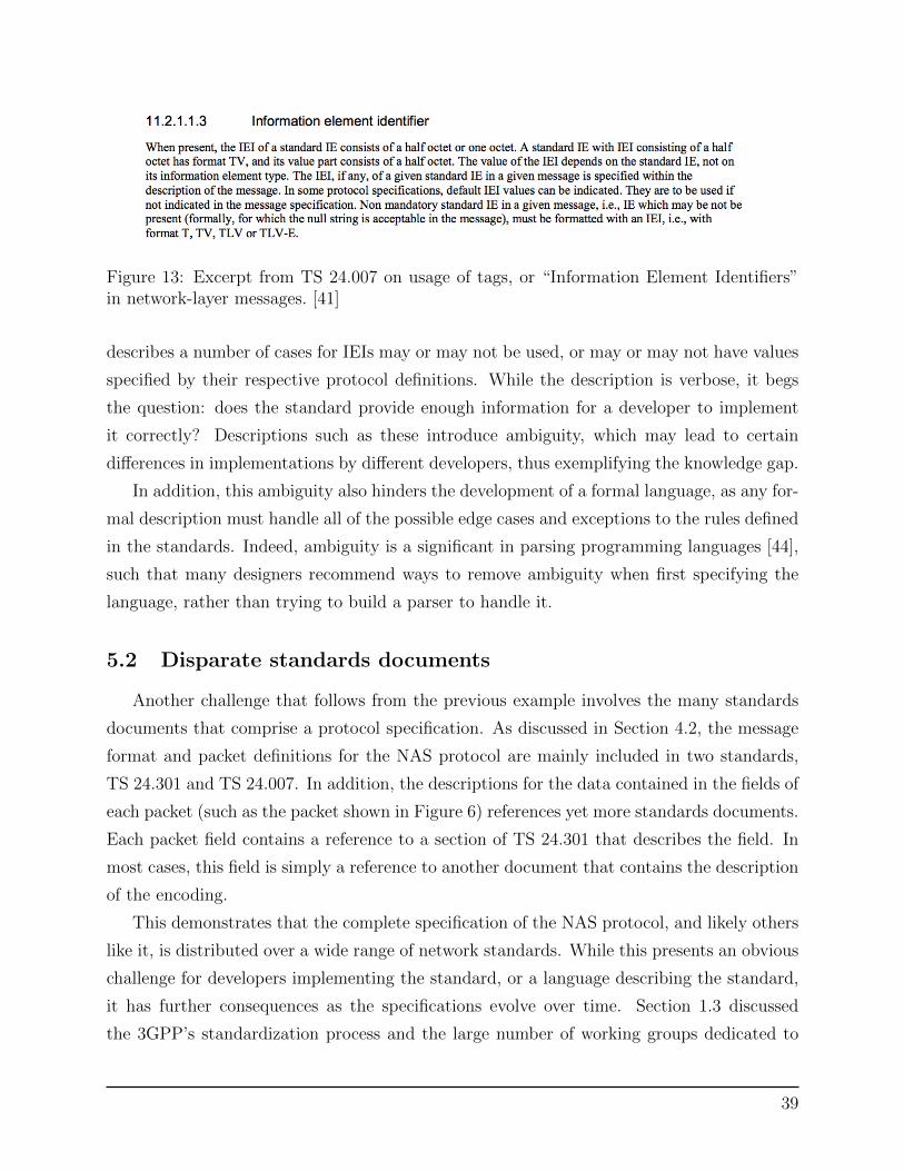
Figure 13: Excerpt from TS 24.007 on usage of tags, or “Information Element Identifiers”in network-layer messages. [41]
describes a number of cases for IEIs may or may not be used, or may or may not have values
specified by their respective protocol definitions. While the description is verbose, it begs
the question: does the standard provide enough information for a developer to implement
it correctly? Descriptions such as these introduce ambiguity, which may lead to certain
differences in implementations by different developers, thus exemplifying the knowledge gap.
In addition, this ambiguity also hinders the development of a formal language, as any for-
mal description must handle all of the possible edge cases and exceptions to the rules defined
in the standards. Indeed, ambiguity is a significant in parsing programming languages [44],
such that many designers recommend ways to remove ambiguity when first specifying the
language, rather than trying to build a parser to handle it.
5.2 Disparate standards documents
Another challenge that follows from the previous example involves the many standards
documents that comprise a protocol specification. As discussed in Section 4.2, the message
format and packet definitions for the NAS protocol are mainly included in two standards,
TS 24.301 and TS 24.007. In addition, the descriptions for the data contained in the fields of
each packet (such as the packet shown in Figure 6) references yet more standards documents.
Each packet field contains a reference to a section of TS 24.301 that describes the field. In
most cases, this field is simply a reference to another document that contains the description
of the encoding.
This demonstrates that the complete specification of the NAS protocol, and likely others
like it, is distributed over a wide range of network standards. While this presents an obvious
challenge for developers implementing the standard, or a language describing the standard,
it has further consequences as the specifications evolve over time. Section 1.3 discussed
the 3GPP’s standardization process and the large number of working groups dedicated to
39

maintaining these standards. As certain standards are updated or extended, there exists the
potential for adding further ambiguities or differences that may have unintended impacts on
the other standards they reference. While this is an inherent challenge to a large network
architecture, a description of the standard as a formal language would help to resolve this is-
sue, as it would enforce a singular representation of the protocol from which implementations
could be developed.
5.3 Inheritance from other network standards
In addition to merely referencing other network standards, many standards are designed
as extensions to previous protocols. This exemplifies the natural evolution of the cellular
network architecture, as discussed in Section 2.1. Many of the fields in the NAS protocol
definition are based on similar protocols or fields in UMTS networks, or even reference
older GPRS standards. In one specific example, one field that encodes a subscriber identity
number, the identity number is encoded in the arcane binary-coded decimal (BCD) format,
further demonstrating that the NAS protocol inherits components from its predecessors [40].
This means that the NAS protocol not only inherits a dependency on these older stan-
dards definitions, but also inherits any ambiguities or edge cases in their specifications or
message formats as well. This significantly complicates a language definition, which would
be required to rectify the disparate components into a single specification. From an imple-
mentation perspective, such reliance on older systems invites code reuse from other imple-
mentations and protocols, which may lead to additional differences between implementations
and thus security vulnerabilities.
5.4 Chapter summary: Recommendations for reducing ambiguity
This section has outlined a number of practices that may introduce ambiguities and
exceptions in network standards. These complications may lead developers to misunderstand
the specification and also hinder the development of a formal representation by adding
further complexity to the way these standards can be parsed. While the addition of a formal
representation in a language would help reduce ambiguity in such a protocol specification,
these issues suggest that further revision is needed in the way the standards are created and
maintained to help reduce the complexity of the standard. In light of this, we make the
following recommendations for future standards in order to aid representation as a language:
40

• Avoid exceptions and edge cases: A number of message formats discussed in Sec-
tion 5.1 contained a number of exceptions and edge cases to support the requirements
so many different implementations. Simply avoiding such edge cases at the time of the
protocol’s design would greatly simply a formal representation.
• Unify disparate representations of protocols: As discussed in Section 4.1, the
NAS protocol’s specification was dependent on a number of other, more general stan-
dards documents, which contained many exceptions and edge cases as a result. Future
standards should avoid such dependencies, or avoid adding further exceptions that
would create further complexity in a general standard.
• Carefully consider reuse of elements from previous standards: Reliance on
message formats from older network standards, which may have their own ambiguities
and edge cases adds further complexity to a standard’s definition. While evolution
from past standards is an inherent part of the development process, significant reuse
may be detrimental by complicating the specification.
This chapter outlined a number of ways that network standards may introduce ambi-
guity or complications that make an implementation or formal representation challenging.
These recommendations identify methods for reducing ambiguity in a protocol specification,
reducing the complexity required to create a formal representation of the language. We hope
that these recommendations can provide guidelines for the development of future protocols
as cellular technologies evolve.
41

6 Discussion and Future Work
6.1 Research contributions
The goal of this project was to identify ways to improve the security of LTE networks.
Our work has focused on providing a tool to help close the gap between standards and
implementation in LTE’s network layer protocols. In doing so, we have:
• Characterized LTE’s security goals and architecture to identify a gap between the
security requirements described in the standards and practical implementations
• Developed a language to express the NAS protocol’s encoding as well as a compiler to
translate the protocol description into an implementation, to provide one example for
closing this gap
• Provided recommendations based on lessons learned during development of the lan-
guage and compiler to support development of future protocols that employ formal
representations
In this way, our work demonstrates how a formal language can be utilized to represent a
cellular network protocol. We hope that our work helps to raise awareness of the disparity
between standards and implementation to support further research on how adding formalism
to network standards can help ensure that the security goals defined in the standards can
be upheld in an implementation.
6.2 Future work
We have outlined a number of extensions to this work that can further improve our
language design and compiler implementation:
• Improve validation of the language and compiler: As discussed in Section 4.3,
we verified our language and compiler design by describing a subset of messages in the
NAS protocol and manually decoding packets to verify their encodings. Further verifi-
cation could be conducted using a sample dataset of NAS traffic created by production
hardware or a commercial traffic generator that implements the NAS protocol. This
would enable further work to implement and verify more message types to help make
our implementation more comprehensive.
42

• Investigate further compiler backends: Our compiler was designed to generate
header files to encode NAS packets, which only represents one portion of a NAS proto-
col implementation. Further work could develop additional code generators that could
use the language representation to perform other functions, such as encoding packets
or generating traffic to help verify other implementations.
• Extend the language design to support more protocol aspects: As discussed
in Section 4.2, our language was designed to specify the encoding formats for NAS
protocols. Extensions to our language design could support further aspects of the
protocol, such as message flows, that describe the critical security features provided by
the protocol.
• Use the language as a verification tool: In addition to generating an imple-
mentation, our language design could also be applied to the research space of formal
verification of existing implementations of other protocols. This may be possible by de-
veloping a compiler backend to target existing verification tools, such as model-finders,
that can help ensure certain security properties are maintained.
We hope that our language and compiler design provides a framework for continued de-
velopment in representing NAS and other protocols. To support this, the source code for our
implementation will be published as an open-source project to enable further development
and community contributions, described further in Appendix A.
6.3 Final discussion
The goal of this project was to provide a method for improving LTE’s security by reducing
the gap between the security goals defined in the standards and practical implementations.
In doing so, we have developed a language design and compiler for representing the encoding
formats of the NAS protocol and generating source that can encode NAS messages. Our
work provides an example of how the formalism provided by a language can helping connect
a protocol’s specification with a practical implementation, which can help ensure that the
security requirements defined by a standard are upheld in practice. In addition, we provide
recommendations based on our work implementing the NAS protocol for how future protocol
designs can more easily utilize formal descriptions. We hope that our work helps to raise
awareness on how formal languages can be used in other standards to help improve their
security.
43

References
[1] I. T. Union, “The world in 2014: Ict facts and figures,” 2014. [Online]. Available: http:
//www.itu.int/en/ITU-D/Statistics/Documents/facts/ICTFactsFigures2014-e.pdf
[2] A. Germano, “The impact of femtocells on next generation lte mobile networks,” Femto-
Forum 3GPP, 2010.
[3] A. R. Doug DePerry, Tom Ritter, “Traffic interception and remote mobile phone cloning
with a compromised cdma femtocell,” DEF CON, 2013.
[4] N. Golde, K. Redon, and R. Borgaonkar, “Weaponizing femtocells: The effect of rogue
devices on mobile telecommunications.” in NDSS, 2012.
[5] G. Association, “History,” 2015. [Online]. Available: http://www.gsma.com/aboutus/
history
[6] 3GPP, “Gprs and edge,” 2015. [Online]. Available: http://www.3gpp.org/technologies/
keywords-acronyms/102-gprs-edge
[7] ——, “Umts,” 2015. [Online]. Available: http://www.3gpp.org/technologies/
keywords-acronyms/103-umts
[8] M. Nohrborg, “Lte,” 2015. [Online]. Available: http://www.3gpp.org/technologies/
keywords-acronyms/98-lte
[9] J. Wannstrom, “Lte,” 2015. [Online]. Available: http://www.3gpp.org/technologies/
keywords-acronyms/97-lte-advanced
[10] 3GPP, “About 3gpp home,” 2015. [Online]. Available: http://www.3gpp.org/
about-3gpp/about-3gpp
[11] ATIS, “Atis - north american organizational partner: 3gpp,” 2015. [Online]. Available:
http://www.atis.org/3gpp/
[12] D. Terdiman, “Unlocking ma bell: How phone phreaks came
to be,” CNET, 2013. [Online]. Available: http://www.cnet.com/news/
unlocking-ma-bell-how-phone-phreaks-came-to-be/
44

[13] M. Green, “On cellular encryption,” A Few Thoughts on Cryptography En-
gineering. [Online]. Available: http://blog.cryptographyengineering.com/2013/05/
a-few-thoughts-on-cellular-encryption.html
[14] M. Rahnema, “Overview of the gsm system and protocol architecture,” Communications
Magazine, IEEE, vol. 31, no. 4, pp. 92–100, 1993.
[15] M. Olawski, “Security in the gsm network,” IPSec. pl. Stream ciphers.
[16] E. Barkan, E. Biham, and N. Keller, “Instant ciphertext-only cryptanalysis of gsm
encrypted communication,” in Advances in Cryptology-CRYPTO 2003. Springer, 2003,
pp. 600–616.
[17] C. Mulliner, N. Golde, and J.-P. Seifert, “Sms of death: From analyzing to attacking
mobile phones on a large scale.” in USENIX Security Symposium, 2011.
[18] S. K. Pell and C. Soghoian, “Your secret stingray’s no secret anymore: The vanishing
government monopoly over cell phone surveillance and its impact on national security
and consumer privacy,” Harvard Journal of Law and Technology, Forthcoming, 2014.
[19] A. Soltani and C. Timberg, “Tech firm tries to pull back cur-
tain on surveillance efforts in washington,” Washington Post. [On-
line]. Available: http://www.washingtonpost.com/world/national-security/
researchers-try-to-pull-back-curtain-on-surveillance-efforts-in-washington/2014/
09/17/f8c1f590-3e81-11e4-b03f-de718edeb92f story.html
[20] M. Richtel, “A police gadget tracks phones? shhh! its secret,” New York Times, 2015.
[21] C. Tang, D. A. Naumann, and S. Wetzel, “Analysis of authentication and key estab-
lishment in inter-generational mobile telephony,” in High Performance Computing and
Communications & 2013 IEEE International Conference on Embedded and Ubiquitous
Computing (HPCC EUC), 2013 IEEE 10th International Conference on. IEEE, 2013,
pp. 1605–1614.
[22] L. Miras, “Baseband playground,” Ekoparty,, 2011.
[23] R.-P. Weinmann, “Baseband attacks: Remote exploitation of memory corruptions in
cellular protocol stacks.” in WOOT, 2012, pp. 12–21.
[24] Z. Lackey and L. Miras, “Attacking sms,” BlackHat 2009, 2009.
45

[25] W. Enck, P. Traynor, P. McDaniel, and T. La Porta, “Exploiting open functionality in
sms-capable cellular networks,” in Proceedings of the 12th ACM conference on Computer
and communications security. ACM, 2005, pp. 393–404.
[26] C. Mulliner and J.-P. Seifert, “Rise of the ibots: Owning a telco network,” in Malicious
and Unwanted Software (MALWARE), 2010 5th International Conference on. IEEE,
2010, pp. 71–80.
[27] P. Traynor, M. Lin, M. Ongtang, V. Rao, T. Jaeger, P. McDaniel, and T. La Porta,
“On cellular botnets: measuring the impact of malicious devices on a cellular network
core,” in Proceedings of the 16th ACM conference on Computer and communications
security. ACM, 2009, pp. 223–234.
[28] R. B. Borgaonkar, “Security analysis of femtocell-enabled cellular network architecture,”
Ph.D. dissertation, Universitatsbibliothek der Technischen Universitat Berlin, 2013.
[29] J. Ravi, “Cell phone tower,” Wikimedia Commons, 2011. [Online]. Available:
https://commons.wikimedia.org/wiki/File:Cell Phone Tower.jpg
[30] P. Team, “Verizon network extender review,” PhoneArena, 2009. [Online]. Available:
http://www.phonearena.com/reviews/Verizon-Network-Extender-Review id2110
[31] “Samsung network extender,” Verizon Wireless, 2015. [Online]. Available: http:
//www.verizonwireless.com/accessories/samsung-network-extender-scs-2u01/
[32] 3GPP, “Security of home node b (hnb) / home evolved node b (henb),” 3GPP Technical
Specification 33.320, Release 12, 2013.
[33] I. Bilogrevic, M. Jadliwala, and J.-P. Hubaux, “Security issues in next generation mobile
networks: Lte and femtocells,” in 2nd international femtocell workshop, no. EPFL-
POSTER-149153, 2010.
[34] N. Golde, K. Redon, and J.-P. Seifert, “Let me answer that for you: Exploiting broadcast
information in cellular networks,” in Proceedings of the 22nd USENIX conference on
Security. USENIX Association, 2013, pp. 33–48.
[35] R. Borgaonkar, N. Golde, and K. Redon, “Femtocells: a poisonous needle in the oper-
ator’s hay stack,” Black Hat Las Vegas, 2011.
[36] Alcatel-Lucent, “The lte network architecture: A comprehensive tutorial,” 2009.
46

[37] H. Welte, “Anatomy of contemporary gsm cellphone hardware,” Unpublished paper, c,
2010.
[38] J. B. Postel, “Rfc 821: Simple mail transfer protocol,” IETF, 1982. [Online]. Available:
https://tools.ietf.org/html/rfc821
[39] Google, “Transparency report: Email encryption in transit,” 2015. [Online]. Available:
https://www.google.com/transparencyreport/saferemail/
[40] 3GPP, “Non access stratum (nas) protocol for evolved packet system (eps),” 3GPP
Technical Specification 24.301, Release 12, 2014.
[41] ——, “Mobile radio interface signalling layer 3; general aspects,” 3GPP Technical Spec-
ification 24.007, Release 12, 2013.
[42] T. Parr, “Antlr,” 2014. [Online]. Available: http://antlr.org
[43] W. Foundation, “Wireshark,” 2015. [Online]. Available: https://wireshark.org
[44] D. Grune, K. van Reeuwijk, H. E. Bal, C. J. Jacobs, and K. Langendoen, Modern
compiler design. Springer Science & Business Media, 2012.
47

Appendix A: Project source code
The source code for our design will be published as an open-source project and maintained
at: http://github.com/ndemarinis.
48