on limitations of friendly jamming for confidentiality · on limitations of friendly jamming for...
TRANSCRIPT

On Limitations of Friendly Jamming for Confidentiality
Nils Ole Tippenhauer, Luka Malisa, Aanjhan Ranganathan, Srdjan Capkun
Institute of Information SecurityETH Zurich
Zurich, Switzerland{tinils,malisal,raanjhan,capkuns}@inf.ethz.ch
Abstract—Wireless communication provides unique securitychallenges, but also enables novel ways to defend againstattacks. In the past few years, a number of works discussed theuse of friendly jamming to protect the confidentiality of the com-municated data as well as to enable message authentication andaccess control. In this work, we analytically and experimentallyevaluate the confidentiality that can be achieved by the use offriendly jamming, given an attacker with multiple receivingantennas. We construct a MIMO-based attack that allows theattacker to recover data protected by friendly jamming andrefine the conditions for which this attack is most effective.Our attack shows that friendly jamming cannot provide strongconfidentiality guarantees in all settings. We further test ourattack in a setting where friendly jamming is used to protectthe communication to medical implants.
I. INTRODUCTION
The shared nature of the wireless communication channel
poses numerous security challenges, from eavesdropping by
a nearby attacker to selective interruption of communica-
tion by jamming. However, the physical layer of wireless
communications also enables novel ways to defend against
attacks. For example, wireless transceivers can collaborate
in order to prevent an attacker from interfering with, as
well as eavesdropping on, their communication. Recently,
a number of schemes were proposed in this space [1]–[7];
these schemes use the idea of friendly jamming—intentional
signal interference by collaborating and coordinated devices.
Friendly jamming is typically used to achieve the follow-
ing goals: (i) to prevent an attacker from communicating
with a protected device, and (ii) to prevent the attacker
from eavesdropping on messages sent by protected devices.
The first goal is related to access control, authentication
and intrusion detection, and is typically achieved by a
friendly jammer who jams all traffic to or from a protected
device [8]–[10]. The second goal is confidentiality and is
achieved in this setting by exposing the attacker to friendly
jamming such that the attacker’s channel, unlike the channel
of the protected receiver, is degraded to such an extent that
successful decoding of messages becomes infeasible.
We focus on confidentiality provided by friendly jamming
schemes. Although it might seem that the use of jamming for
confidentiality is unnecessary because confidentiality can be
simply achieved by encryption, there are numerous scenarios
where key distribution, performance, mismanagement, or
legacy issues prevent the establishment or use of shared
keys. One example is the case of medical implants, where
access to the implant data is safety-critical and must be
granted to medical professionals in all circumstances, even
in foreign domains to which appropriate credentials or keys
cannot be distributed [11], [12]. Another example is a
corporate setting where friendly jamming can be used as a
second layer of protection against unintentional information
leakage, mitigating the risk that misconfigured or legacy
systems do not use appropriate encryption [13]. Furthermore,
jamming can be used to protect initial key establishment, e.g.
in sensor networks [14].
Friendly jamming schemes that aim to achieve confiden-
tiality rely on the assumption that it will be hard for the
attacker to extract the message, as the jamming signal from
the friendly jammer and the signal carrying the confidential
message superimpose at the attacker’s antenna(s). The signal
at the attacker’s antennas and thus his ability to extract
the message depends on many factors: the jamming and
message signals, the mutual distances between the jammer,
message source and the attacker, their locations as well
as the environment itself. Some related work on friendly
jamming assume scenarios where the attacker has limited
capabilities in terms of the number or directionality of his
antennas and antenna placement [1], [2], [15]. Other related
works such as [11], [16] do not assume an attacker that is
restricted in terms of the number of antennas but instead
argue that one can defend against a MIMO eavesdropper
or an eavesdropper with a directional antenna by ensuring
that the friendly jammer is located significantly less than
half a wavelength from the data source. These works also
show that if the attacker is equipped with a single antenna,
proximity alone is not sufficient for confidentiality, but that
the ratio between the jammer and data source power is
equally a critical parameter. These arguments are based on
channel models and signal processing techniques commonly
used in wireless communication research. However, the
effectiveness of friendly jamming has so far not been studied
in scenarios in which the attacker is equipped with multiple
antennas.
In this work we analyze friendly jamming in scenarios
where the friendly jammer and the message source are
physically very close (closer than half of the signal’s carrier
2013 IEEE Symposium on Security and Privacy
1081-6011/13 $26.00 © 2013 IEEE
DOI 10.1109/SP.2013.21
160

��� � �
�
(a)
�� � �
��
(b)
Figure 1. Two common friendly jamming scenarios. In both, the attacker A is jammed by J and is unable to eavesdrop on a message M transmitted bythe transmitter D. The legitimate receiver R can still receive the message. We differentiate between the scenario in which the data source (D) and friendlyjammer (J) are far (a) and when they are close (b).
wavelength), given an attacker with two receiving antennas.
We introduce a new type of an attack, based on MIMO, that
allows the attacker to recover confidential messages from
distances sufficient for a practical attack. We demonstrate
our attack both analytically and experimentally.
In our analytical evaluation, based on a Line-of-Sight
(LoS) model, we show that the attacker can recover the
confidential message even when the friendly jammer and
the data source are few centimetres apart and the attacker is
several meters away.
Our experiments were done in the 402− 405MHz MICS
band. In our LoS experiments, the friendly jammer and the
data source were placed 15 − 30 cm apart (less than half a
wavelength for the MICS band). In this setting, we demon-
strate the successful recovery of confidential messages by
an attacker from up to 3m away, and in some cases from
further distances. In our NLoS measurements, we placed
the data source (a USRP) behind a layer of bacon and
ground beef, simulating a medical implant in human flesh
and we positioned the friendly jammer within 5 − 7 cm of
the data source. In this setting we were able to recover
confidential messages from distances of up to 2m with
success rates depending on environmental conditions. The
above distances between the jammer, data source and the
attacker correspond to many practical settings. Our results
also raise security concerns with the use of friendly jamming
for the protection of confidentiality of messages transmitted
by medical implants.1
1In our experimental results we shape the jamming signal power profilefor the FSK modulated data that our data source uses. The works in [11],[16] generate friendly jamming signal by combining multiple random whiteGaussian signals and by matching the shape of their power profile to thatof the implant. In this work, we do not restrict the type of jamming signalthat the friendly jammer generates as our attack helps in eliminating thejamming signal regardless of its type.
In this work we consider a relatively strong attacker,
who can place his antennas at chosen locations in the
vicinity of the victim’s system. Nevertheless, we believe
that in a number of scenarios, especially those where the
message source and the jammer are static (e.g., a patient
lies stationary during medical examination or a computer
that is used in an office), this attacker model is practical. In
the case of a mobile victim, our attack can still be used to in-
termittently recover parts of transmitted messages, violating
the confidentiality provided by friendly jamming schemes.
Note that since the transmitted messages are not protected
by any form of encryption, but that their confidentiality is
typically solely protected by friendly jamming, the attacker
may be able to recover full messages even if he is able to
receive only individual message fragments.
Through our analysis and experiments, we demonstrate a
fundamental limitation of friendly jamming schemes when
they are used for confidentiality and we refine the conditions
under which such schemes can be used. Our results however,
do not pertain only to friendly jamming, but can also be
seen as a further refinement of attacker models used in the
analysis of physical-layer security schemes—they highlight
again the importance of precise modeling of attacker’s
capabilities.
The structure of the paper is as follows. We give back-
ground information on friendly jamming schemes in Sec-
tion II. We then analyze the underlying model and assump-
tions in detail in Section III and show analytically under
which circumstances the attacker can eliminate the jamming
signal. We validate our findings experimentally in Section IV
and show that a practical attacker can remove the jamming
signals and recover the data. In Section V, we discuss the
impact of our findings and possible countermeasures. We
conclude the paper in Section VI.
161

II. BACKGROUND
In the context of confidentiality, friendly jamming is used
in a scenario in which devices rely on a friendly jammer to
prevent the attacker from overhearing the messages that they
exchange. A typical friendly jamming scenario consists of
four parties: a transmitter, receiver, attacker and a jammer.
The jammer’s goal is to sufficiently degrade the channel be-
tween the transmitter and the attacker such that the attacker
cannot decode the messages coming from the transmitter.
However, the jammer must not prevent the receiver from
decoding the messages.
We differentiate between two types of friendly jammer
systems:
• Remote jammer systems. In these systems, the dis-
tance between the transmitter and the jammer is much
larger than half a carrier wavelength. Here, a common
security assumption is that the attacker is equipped with
a single omni-directional antenna and thus cannot sepa-
rate the confidential message from the jamming signal.
However, in a number of scenarios, an attacker can
still try to use antenna directionality to his advantage
and extract the exchanged message. A remote jammer
system is illustrated in Figure 1(a).
• Nearby jammer systems. In these systems, the jam-
mer and the transmitter are less than half a carrier
wavelength apart. The main security assumption here
is that, in these systems, the jamming and data signal
envelopes are highly correlated ( [17] § 13.2.1) and are
thus assumed to be inseparable. We later show that this
assumption does not always hold. A nearby jammer
system is illustrated in Figure 1(b).
A. Friendly Jamming Schemes
Secrecy capacity [18] is a key notion in the information-
theoretic aspects of wireless security. It is defined as the
difference between the capacity of the intended communi-
cation channel and the capacity of the eavesdropper channel.
Prior work discusses a number of ways of quantifying and
increasing the secrecy capacity bounds of various types
of wireless channels. Proposed systems rely on one or
more relay nodes [1]–[4], multi-antenna transmitters [19]
or friendly jammers [5], [6] to increase secrecy capacity
by enhancing the receiver’s and degrading the attacker’s
channel. Proposed systems considered a single [6] as well
as multiple friendly jammers [7]. All the schemes primarily
considered only remote jamming.
A common attacker model used in the analysis of these
schemes was based on a single, passive eavesdropper [4]–
[6], [20] and if resilience against multiple eavesdroppers was
considered, eavesdropper collusion was not made a part of
the model [1], [19].
Goel and Negi [21] consider the case of transmitter,
receiver and attacker all having multiple antennas. However,
�
�
�
Figure 2. The scheme proposed in [11]: To secure communication to theimplant, the patient wears an IMD shield. The shield (J) serves as a friendlyjammer and prevents all direct communication to an IMD and makes surethat unauthorized devices (A) cannot decode messages transmitted by theIMD. A programming device (P ) which wants to communicate with theIMD has to first establish a secure channel with the shield.
the total number of attacker’s antennas in their analysis is
less than or equal to the number of transmitting antennas.
Pinto et al. [22] consider a more powerful attacker. They
analyze the secrecy capacity in the presence of colluding,
spatially-separated eavesdroppers. Within their model, the
eavesdroppers are allowed to share and combine information
to improve their chances of successfully decoding a message.
The authors conclude that an increasing number of colluding
eavesdroppers drastically reduces the achievable secrecy
capacity.
Kuo et al. consider the problem of secure initialization
of nodes in sensor networks [14]. The proposed scheme
employs a Faraday cage in order to significantly attenuate
signals which carry secret keying information. A friendly
jammer is placed outside of the Faraday cage to further
interfere with any potential eavesdroppers.
In the following, we describe a scheme that considered
the use of nearby jamming.
Gollakota et al. propose the use of nearby jamming to
ensure confidentiality and access control to implantable
medical devices (IMDs) [11].
In this scheme, a friendly jammer aims to protect an
“insecure” IMD, i.e., an IMD that does not implement any
security mechanisms. Without this protection, an attacker
could freely communicate with, as well as eavesdrop on,
data transmitted by the IMD. This would pose both safety
risks (malicious reconfiguration of the device) and privacy
concerns (leakage of private information). To protect against
these attacks, the user wears an additional device on a
necklace—the shield. The shield acts as a gateway for exter-
nal devices who want to communicate with the IMD—it will
prevent any direct external communication to the IMD by
jamming unauthorized queries of the IMD. In addition, the
shield will jam any transmissions from the IMD, preventing
anyone from eavesdropping on the message content. The
shield itself can cancel out his own jamming signal and
can thus correctly demodulate the data sent by the IMD.
162
Consequently, anyone who wishes to communicate with
the IMD must first contact the shield, who then forwards
the communication to the IMD. Because the shield is an
external device, unlike an IMD, it can easily establish a
secure channel to any legitimate reader.
For an attacker with a single antenna, the scheme ar-
gues that given close proximity of the jammer to the
data source, sufficient jamming power, and a well-formed
jamming signal, an attacker cannot recover the data signal.
To defend against an attacker with multiple antennas, the
work assumes that the respective channels of the IMD and of
the shield to the attacker cannot be separated with directional
antennas or techniques such as MIMO if the IMD and the
shield are significantly less than half of the communication
signal wavelength apart. As reasoning for this, it refers to
Chapter 1 in [23] and Chapter 7 in [24] — these references,
however, do not explore the use of MIMO-like techniques
in adversarial settings. In the example of medical implants,
this work considers a distance of few centimeters, without
giving a precise threshold. In terms of the attacker, the only
other restriction that is imposed is that the attacker must
be located further away from the jammer than the implant
(e.g., at distances 20 cm and greater). The attacker is not
restricted in terms of the number, location, or directionality
of the antennas that he uses. Despite considering a strong
attacker, the work focuses the evaluation of the proposed
scheme on an attacker with a single antenna.
III. JAMMING MITIGATION USING CHANNEL
RESOLUTION
Friendly jamming can only achieve data confidentiality if
the attacker cannot recover the data signal. Remote jammer
schemes, where the friendly jammer is far (> λ/2) from
the transmitting device, were studied in prior work and their
limitations in terms of attacker placement as well as number
and directionality of his antennas are well known. Nearby
jammer schemes promised to significantly raise the security
guarantees, based on the assumption that the friendly jammer
and the transmitting device are collocated. They pose no
special restrictions on the attacker, except that he is not too
close to the jammer or the transmitter. We focus on nearbyjammer schemes and show that their security guarantees are
weaker than it was so far believed.
The security of friendly jamming schemes is typically
argued by considering signal strengths, non-separability of
channels using MIMO techniques, and the information rate
of the combined data/jamming signal. Here, we investigate
channel non-separability arguments in more detail and ana-
lyze whether it is possible for the attacker to use techniques
similar to MIMO in order to separate the jamming and data
signal even if the jammer and transmitter are close.
We begin with a brief example of the attack to give an
intuition, and then derive why the attacker, in our setting, is
able to separate the data signal from the jamming signal.
A. Example of our Attack
Consider the following scenario shown in Figure 3b. The
attacker is equipped with two antennas (A and B) which
are equidistant from the jamming source (AJ = BJ), but
not equidistant from the data source (AD �= BD). Both
antennas receive a composite signal, consisting of a data
component as well as a jamming component. As a result,
the received signal at A and B have each a different relative
phase offsets between the data and signal component.
Because both antennas of the attacker are equidistant to
the jammer, the signal received by both antennas will contain
the jamming signal with same phase. The data component
is received with some phase offset δ depending on the geo-
metric setting. Lets assume that in this example, the phase
shift is equal to half a wavelength, i.e., δ = π (in radians).
In Figure 3a we depict the two received signals as well
as their individual components. By subtracting the received
signals, the attacker can remove the jamming component
and obtain an amplified data component. Since the jamming
components have the same amplitude and phase, it is easy
to see that they are eliminated when the signals are sub-
tracted. Differently, when two λ/2-shifted data components
are subtracted, they constructively interfere, resulting in an
amplified data signal.
From this example, it follows that there are indeed con-
stellations in which the attacker can recover the data signal.
We now investigate these conditions in more detail. We
first briefly review a standard MIMO line-of-sight (LOS)
channel model which states that the channel should not be
resolvable and signals should not be separable. We show
why this channel model does not exactly capture our use case
here—it requires a certain minimal distance between sender
and receiver. We then compute the approximation error of
this standard model for the nearby jammer case. Finally, we
identify a way to separate the data and jamming channel
leveraging the observation on the approximation error and
show, for selected settings, resulting bit error rates of the
attacker when he recovers the data signal.
B. MIMO Basics
In this context, multiple-input and multiple-output
(MIMO) denotes a setting in which a transmitter uses mul-
tiple antennas to transmit a wireless message to a receiver
with multiple antennas. Among other aspects, the channel
diversity between the transmitting and receiving antennas
enables the receiver to improve the received signal quality in
presence of fading channels and can also be used to improve
spectral efficiency. For example, multiple antennas can pro-
vide a simple power gain when aligned correctly. Multiple
antennas can also help to mitigate random effects of channel
fading. A normal MIMO setting assumes that sender and
receiver are collaborating to improve their communication.
In our setting, we are investigating whether the attacker can
recover signals sent by the transmitter in the presence of
163

���������
�����
������
������������������������
��
���
�
�
�
� � �
�
�
��
��������������
��� ���
�
�
�
�
�
Figure 3. A simplified scenario which illustrates our attack. Both the data source D and attacker E are within the jammed area. In this example, theattacker is equipped with two antennas (A and B) which are equidistant from the jamming source, i.e., AJ = BJ . The antennas are not equidistant fromthe data source.
a jammer, without the collaboration of neither jammer nor
transmitter. For a thorough introduction into MIMO, we refer
to [24].
C. Line-of-Sight MIMO Model
For our discussion, we assume that the attacker has two
omni directional antennas (A,B) which he can place at any
distance to the jammer J that is greater than the distance
between the jammer J and the data source D antennas. We
further consider a case in which the transmitting antennas
(D and J) are placed less than λ/2 apart from each other.
A standard way to model wireless transmissions in our
setting is the following description:
y = Hx+ w
Applied to our use-case, y = [sA sB ]T is the column
vector of signals received by the attacker, H is a channel
matrix, x = [sd sj ]T is the vector of source signals and
w is additional random channel noise. For the following
discussion, we omit the noise to simplify the equations.
The channel matrix H depends on the chosen channel
model. Here, we approximate the channel as several line-
of-sight paths. For this setting, a standard channel model
can be found in § 7.2.3 in [24], on which we will base
our discussion. We call the resulting channel matrix Hm to
differentiate from a second model we will introduce later.
The channel model Hm assumes that all transmitted
signals experience the same channel conditions and arrive
�
�
�
�
Figure 4. The geometric model for the IMD shield use case.
only with small phase offsets approximated based on the
geometric setup. To simplify the computations, the model
assumes that all signals are received along the same direc-
tion between A and D (shown in Figure 4). The relative
position of the other receiving antenna with regards to Ais expressed as distance Δrλ and the angle φr, the same
for the transmitting array with φt and Δtλ, respectively. Δt
and Δr are the length of the transmit and receive arrays,
normalized to the wavelength λ. To simplify the formulas,
we define Ω := cosφ. Based on these variables, the model
presents Hm as:
Hm = 2a exp
(−j2πd
λ
)er(Ωr)et(Ωt)∗ (1)
with
er(Ω) :=1√2
[1
exp(−j2πΔrΩ)
](2)
164

0 2 4 6 8 10 12 14 16 18 200
0.2
0.4
0.6
0.8
1
1.2
1.4
1.6
1.8
2
distance d in λ
δ in
rad
ians
Value predicted by Hm
Maximal value of δ with Δt=π .
Maximal value of δ with Δt=1
Figure 5. Approximation error for δ in the rectangular formation settingwith Δr = Δt = 0.5.
and
et(Ω)∗ := 1√2
[1 exp(−j2πΔtΩ)
](3)
and an attenuation factor a.
It can be seen that Hm has rank 1 and thus y must also
have rank at most 1. Indeed, although y has a dimension
equal to the number of antennas of the receiver, all antennas
essentially receive a linear combination of the same signals
if the rank of y is 1. It follows that the sources cannot be
separated based on these linear combinations alone.
In this way, the channel model Hm states that the attacker
cannot eliminate a second nearby signal source such as a
friendly jammer.
D. Analysis of Approximation Error
In § 7.2.3 in [24], an assumption for the MIMO model
we used was:
“Assuming again that the antenna array sizes are
much smaller than the distance between the trans-
mitter and the receiver [...]”
We now examine the approximation error of this LOS
MIMO model for our use case (in which the antenna array
sizes is not “much smaller” than the distance) and how this
approximation error influences the security of the proposed
friendly jamming scheme.
To summarize the parameters for the model, in our
use case we have two antenna arrays (RX/TX), with two
antennas each. The two antennas of the transmitting array
are set up such that Δt ≤ 0.5. The distance d between
the transmitting and receiving array is between 1 and 10wavelengths , thus violating the model assumption regarding
distance. In this setting, we are in particular interested in the
phase offset between the two transmitted signals sd, sn at the
two receiving antennas.
�
�
�
�
Figure 6. A simple rectangular model with Δrλ = Δtλ.
B
A
J
D
Figure 7. Geometry of the simulations: all 4 antennas form an isoscelestrapezoid. The simulations are run for varying d and AB
For simplicity, we will start with showing the approx-
imation error for a rectangular formation (Figure 6) with
distance d between the RX/TX arrays and each arrays with
two antennas Δr = Δt apart (both distances measured in
carrier wavelengths). For this, we insert φt = φr = 90◦ (via
Ωr and Ωt) into Equation 2 and Equation 3, which allows
us to rewrite Equation 1 as the following channel matrix,
which we will denote as Hm:
Hm = a
[e−j2πd/λ e−j2πd/λ
e−j2πd/λ e−j2πd/λ
]
Based on the geometry of the formation, we now also
compute the correct phase shifts, and derive our correct
channel matrix, which we call Hg), as
Hg = a
[e−j2πd/λ e−j2π
√d2+Δ2
t/λ
e−j2π√
d2+Δ2t/λ e−j2πd/λ
]
As Hg is clearly different to Hm (e.g. Hg has rank 2 for
Δt > 0 and a �= 0), the simplified model Hm has to have
some approximation error. In particular, we are interested
in the difference of phase offsets of the data and jamming
signal, i.e. δ = ∠h11−∠h12−∠h21+∠h22, where ∠hij is
the phase of the ith row and jth column entry of a channel
matrix H . For the model from [24], δ(d) = 0. In Figure 5,
we show the approximation error of the model for small
distances d, up to 20 times the carrier wavelength. It can be
seen that up to a distance of 2.5 wavelengths, δ can reach
0.1 and more. As we show later, such values for δ can allow
the attacker to eliminate the noise signal and recover the data
signal perfectly. Thus, the simplified approximation in Hm
should only apply to values of d much larger than λ, as was
the condition stated for the model.
165

0 100 200 300 400 500 600 700 800 900 1000−30
−25
−20
−15
−10
−5
0
5
10
attacker distance in cm
rela
tive
stre
ngth
of r
ecov
ered
dat
a si
gnal
(dB
)
403MHz, AB=100cm, DJ=5cm403Mhz, AB=35cm, DJ=15cm403Mhz, AB=50cm, DJ=15cm403Mhz, AB=100cm, DJ=15cm2.4GHz, AB=35cm, DJ=15cm2.4GHz, AB=50cm, DJ=15cm2.4GHz, AB=100cm, DJ=15cm
Figure 8. Theoretical limits for data signal amplification with simultaneousjamming signal elimination. In this plot, we assume an isosceles trapezoidformation between the signal sources and the attacker.
E. Description of Our Attack
Our attack allows the attacker to mitigate the jamming
signal and recover the data signal in the presence of friendly
jamming. The adversary uses a two-antenna array that he
places in the proximity of the transmitting array which
consists of a data source (D) and a jammer (J). As we
derived earlier, for small distances between the two arrays,
the attacker receives the two sets of jamming and data
signals with a non-negligible phase offset δ. This δ allows
the attacker to combine the signals received by A and Bsuch that the jamming signal component is annihilated and
the data signal recovered.
More precisely, the attacker combines the signals at Aand B to recover a signal y = c exp (−j2πΔc)sd, i.e., a
phase-shifted (by Δc) version of the data signal from Dwith different amplitude c. This signal combination can be
described by a vector r, where
y = rHx
For the example setting before, choosing rg = [hg22 −hg
12]causes the sj component to disappear from y. In other words,
let rg be
rg = [ e−j2πd −e−j2π√
d2+Δ2t ]
then consequently
y =
[e−j2πd
−e−j2π√
d2+Δ2t
]T
a
[e−j2πd e−j2π
√d2+Δ2
t
e−j2π√
d2+Δ2t e−j2πd
]x
which can be simplified as
y = a · sd(e−j4πd − e−j4π√
d2+Δ2t ).
Thus, using rg we obtain y, a phase shifted and amplitude
changed version of sd, where both amplitude and phase
0 100 200 300 400 500 600 700 800 900 10000
0.05
0.1
0.15
0.2
0.25
0.3
0.35
0.4
0.45
0.5
distance in cm
BE
R
403Mhz, AB=100cm, DJ=5cm403Mhz, AB=35cm, DJ=15cm403Mhz, AB=50cm, DJ=15cm403Mhz, AB=100cm, DJ=15cm2.4GHz, AB=35cm, DJ=15cm2.4GHz, AB=50cm, DJ=15cm2.4GHz, AB=100cm, DJ=15cmwithout cancellation
Figure 9. Simulation of expected BER at attacker before and after jammingcancellation. The results are plotted for different carrier frequencies anddistances between the attacker’s antennas. This simulation assumes a 16dBSNR in absence of the jamming signal and considers the w ignored earlier.
depend on the geometry of the setup, in this case d and
Δt. Note that the difference between the phases of both
terms here is the δ discussed earlier. The closer δ is to
±π (in radians), the higher the amplitude of sd in y. The
achievable δ directly depends on r, which itself depends on
the geometry of the setup.
F. Attack Performance in LOS Setting
We now perform simulations to evaluate the performance
of the attack for different values of d and AB. Due to the
many degrees of freedom for the placement of two antennas
of the attacker with respect to D and J , we restrict this
analysis to a symmetric setting, in which the four antennas
form an isosceles trapezoid. While this setting does not cover
all possible placements of the attacker’s antennas relative to
D and J , it shows how the attack performs with respect
to the distance between A and B, and the general distance
between attacker and D and J .
In the setting used in the simulations (Figure 7), all 4
antennas form an isosceles trapezoid where the TX anten-
nas are 15 cm apart (unless noted otherwise), and the RX
antennas are separated by either 35 cm, 50 cm, or 100 cm.
We now investigate the performance for different distances
d between both antenna arrays. Figure 8 shows the maximal
amplitude of the recovered data signal sd in y, relative to the
amplitude sd would have at A in the absence of J . Therefore,
a relative amplitude of 2 denotes a perfect recovery of the
data signal, in which the data components of both antennas
constructively add together and double the amplitude. It can
be seen that even for a close spacing of the TX antennas,
sd can be recovered from a distance of multiple meters,
depending on RX setup, with some attenuation of less than
20 dB. Because of the different wavelength of bands, such
166

as the 403MHz MICS band and the 2.4GHz ISM band,
the values of δ differ, and therefore the amplitude of the
recovered signal differs as well.
We now estimate the expected bit error rate (BER) at the
attacker to make the impact of our attack more intuitive. For
this, we assume the following: the transmitting and receiving
antennas are in the same formation as before (Figure 7),
with the data and jamming antenna spaced 15 cm apart. We
further assume that the attacker can receive the data signal
with low BER in the absence of the jamming signal, so
we assume his signal-to-noise ratio (SNR) to be 16 dB in
the absence of the jamming signal. We now also account
for the receiver noise w we ignored earlier, and assume
that the noise power at both antennas is the same, but the
noise is uncorrelated. Figure 9 shows the impact of the
friendly jamming signal transmitted with 20 dB more than
data signal, for three different configurations of attacker’s
antennas (antennas placed 35, 50, 100 cm apart). For the case
of AB = 100 cm, we also show results for data and jamming
source 5 cm apart. For reference, we also again also plot
data for the ISM band. We now point to a number of
observations that can be made from the figure. First, without
jamming cancellation, the BER at the attacker is 50%, as
expected. This means that if the attacker does not try to
cancel out jamming, he is not able to recover any data
from the transmission. Second, if the attacker’s antennas are
placed 50 cm apart, the attacker can receive the data signal
with a fairly low BER from a distance of up to 1m from
the transmitter. The BER only reaches 40% at distances of
more than 3m. Third, increasing the distance between the
antennas of the attacker further improves performance—with
attacker’s antennas placed 1m apart, the data signal can be
recovered with minimal BER at around 2 meter distance.
Note that even if the attacker exhibits a high BER, he might
learn some information about the transmitted message. Since
the messages are not protected by any form of encryption,
the attacker might be able to recover the full message even
at a high BER.
So far, we have assumed that the attacker can perfectly
align the jamming signal received on both his antennas. We
will validate this assumption in our experiments.
G. Summary of our Simulation Results
Our results show that our attack indeed allows the at-
tacker to recover the data signal in the presence of friendly
jamming. While the range of the attack for the 403MHz
case is limited to at most a few meters (depending on the
antenna setup of the attacker), the efficiency of the attack
increases for higher carrier frequencies such as 2.4GHz (e.g.
IEEE 802.11) if DJ is kept constant. For these frequencies,
the attacker should be able to mitigate the jamming signal
for distances of up to 10m with a 1m spacing between his
antennas.
����
������ ����� ���
���� ���
�������������
��
�������
������
����
�
�
�
�
���������������
������
�
Figure 10. Experimental setup showing the two attacker antennas, the datatransmitting USRP and the friendly jammer.
�
� �
�
Figure 11. The attacker uses two antennas (A and B) and an oscilloscopein order to record the combined data (D) and jamming (J) signals. Foreach measurement, the attacker antennas were manually moved around(but maintaining the distance ‘d’ between AB and DJ) until the data andjamming signal were reasonably separable during post-processing (detailsin Section V-A).
While these distances might not seem threatening at first,
we note that e.g., in the case of medical implants, the
communication range of IMD devices is also very limited in
normal operations. Our attack shows that friendly jamming
fails to protect the confidentiality of communication in the
MICS band.
While we concentrated on a specific geometric setup in
our evaluation, the attacker is not restricted to the isosceles
trapezoid setting (we discuss this more in Section V-A). In
addition, the attacker can use more than two antennas to
improve his performance.
IV. EXPERIMENTAL ANALYSIS
In this section, we experimentally verify the attack de-
scribed in Section III. First, we describe the experimental
setup used to demonstrate the feasibility for an attacker to
successfully demodulate data (within acceptable bit error
rates) in the presence of a friendly jammer. Then we give
167

Figure 12. Frequency spectrum of the jammer and data signal.
a brief overview of the evaluation metric used in the ex-
periments. Finally, we present our experimental results and
discuss their implications.
A. Experimental Setup
Our experimental setup consists of an attacker (here, a
passive eavesdropper), a data transmitter and a friendly
jammer. Figure 10 shows a block schematic of the complete
setup and Table II summarizes the system parameters used
in the experiments. We further describe the details of our
setup below.
1) Data Source and Friendly Jammer: Two Universal
Software Radio Peripherals (USRPs) are used to emulate
the data transmitter (D) and the friendly jammer (J). Both
entities D and J transmit using 0 dB gain omni directional
antennas. A picture of the data-jammer setup is shown in
Figure 11. Each data packet is 67 bits long with a 29 bitpreamble. The preamble is chosen such that it has high
auto-correlation properties. Data is modulated using binary
frequency shift keying, i.e., 1’s and 0’s are transmitted using
two discrete frequencies. In our setup, the two frequencies
are separated by 100KHz and upmixed to a RF carrier
frequency of 403MHz. The jamming signal is generated by
modulating random bits, which results in a spectrum closely
matching the spectrum of the data signal (Figure 12). It is
ensured that the jamming signal is always transmitted with
at least 20 dB more power with respect to the data signal.
2) Attacker: The attacker is implemented using two omni
directional vertical antennas connected to an oscilloscope
(Figure 11). For the experiments, the two attacker antennas
were placed AB = {35, 50} cm apart. In the experimental
setup, the attacker experiences multipath effects due to
reflection in the lab. Thus, the isosceles trapezoid formation
used in the LOS simulations does not necessarily provide
the optimal results. Consequentially, we allowed the attacker
to adapt the antenna placement to maximize performance,
while preserving the distance d to D, J and the distance
between the attacker antennas AB. As we will show later,
at some locations we were not able to find ideal placements
for the antennas of the attacker.
The received signals were recorded using two different
oscilloscope channels at a sampling rate of 10GSa/s and
later processed using Matlab [25].
1. lag = crosscorr(yA, yB)2. yA = shift(yA ± lag) or yB = shift(yB ± lag)3. yc = yA − yB4. y = fskdemod(downmix(yc))
Table IPSEUDO CODE OF THE JAMMING MITIGATION TECHNIQUE
IMPLEMENTED IN MATLAB.
3) Matlab Implementation: First, the signals are
bandpass-filtered to exclude unwanted channel activity.
Then the power levels of the signals are normalized
to match the amplitudes. As the signals are dominated
by the jamming components, this improves the match
of the two jamming components. The signals are then
phase-aligned by cross-correlating both the recorded signals
and determining the time lag between the two. Based on
the lag, one of the two received signals is appropriately
shifted. Since the jamming signal is assumed to have
considerably higher power compared to the data signal,
the cross-correlation effectively aligns the jamming signal
components while keeping the existing phase difference
between the data signal components intact. Computing
the arithmetic difference between the two aligned signals
results in the recovered data signal—this recovered signal is
an attenuated or amplified copy of the original data signal
as described in Section III. Figure 13 shows the signals
received at the two attacker antennas and the recovered
data signal post alignment and subtraction. The transmitted
data is determined after appropriate synchronization and
FSK demodulation of the recovered data signal. If yA and
yB are the signals received at the attacker antennas A and
B, the stepwise Matlab implementation is summarized as
pseudo code in Table I.
B. Evaluation Metric
The attacker’s ability to successfully recover the data
signal is evaluated based on the bit error rate of the de-
modulated data from the received signal y when compared
to original data in the transmitted signal sd. We express the
number of bit errors in the recovered data as a percentage
of data packet length. In our experiments, we vary the
distance between the attacker and D, J , and the power
levels of the jamming signal relative to data signal. For each
configuration, 15 different measurements were recorded and
the mean bit error rate computed.
168

40cm 50cm 70cm 1m 1.5m 2m 3m 3.5m 4m0
5
10
15
20
25
30
35
40
45
50
Distance of the attacker from DJ (d)
BE
R (
%)
DJ=15cm; AB=35cmDJ=30cm; AB=35cmDJ=30cm; AB=50cm
(a)
20 dB 25 dB 30 dB 35 dB0
5
10
15
20
25
30
35
40
45
50
Relative Power of Jammer to Data
BE
R (
%)
DJ=15cm
DJ=30cm
(b)
Figure 14. (a) Bit error rates obtained by the attacker while at various distances away from the data-jammer antenna configuration. The data and thejammer were configured to transmit in the MICS 403MHz band. The BERs indicated in the plot are arithmetic mean of 20 signal acquisitions at eachlocation. Every data point is an average over 20 measurements and data-jammer transmitting frequencies were centered around 403MHz. (b) Minimumjammer power required to prevent a passive eavesdropper 1m away from the data transmitting antenna.
Figure 13. Black and gray waveforms correspond to signals acquired fromtwo receiver antennas. Once the signals were aligned and subtracted, in redwe can see the clearly visible, remaining data signal component.
C. Measurements and Analysis
In this section, we present our experimental results and
briefly discuss their implications.
1) Effect of Attacker’s distance: As described in Sec-
tion III, the relative strength of the recovered data signal
degenerates as the distance of the attacker from D, J in-
creases. We experimentally verify our model and determine
the maximum distance at which an attacker can successfully
recover the data signal in real-world channel settings. The
power of the jamming signal is configured to be 20 dBmore than the data signal. For every distance between the
Parameter ValueAttackerAntenna type Omni-directional verticalNo. of antennas 2Sampling rate 10GSa/sData transmitterAntenna type Omni-directional verticalCarrier frequency 403MHzBandwidth (β) 300KHzPacket length 67 bitsData rate 150KbpsJammerAntenna type Omni-directional verticalJamming bandwidth 300 kHzNoise type Spectrum shaped random noiseRelative Power of Jammer {20, 25, 30, 35} dB
Table IISUMMARY OF THE SYSTEM PARAMETERS IN EXPERIMENTAL SETUP.
attacker and D, J , two sets of measurements are taken
setting the spacing between the data and jammer antennas
to 15 cm and 30 cm. The results of our experiments are
shown in Figure 14(a). The results show that the attacker can
efficiently recover data for distances greater than one meter
by using a small antenna array with AB = 30 cm when the
data source and jammer are closer than λ/2. By increasing
AB to 50 cm, we were able to recover data with less than
20% BER from a distance of 4m. For smaller values of DJor AB, the BER of the recovered data signal at the attacker
increases, as predicted in our simulation results presented in
Section III. Due to multipath effects in our lab environment,
we were not able to find a good placement for the antennas
around d = 1.5m.
169
50cm 1m 2m0
5
10
15
20
25
30
35
40
45
50
Distance of the attacker from DJ (d)
BE
R (
%)
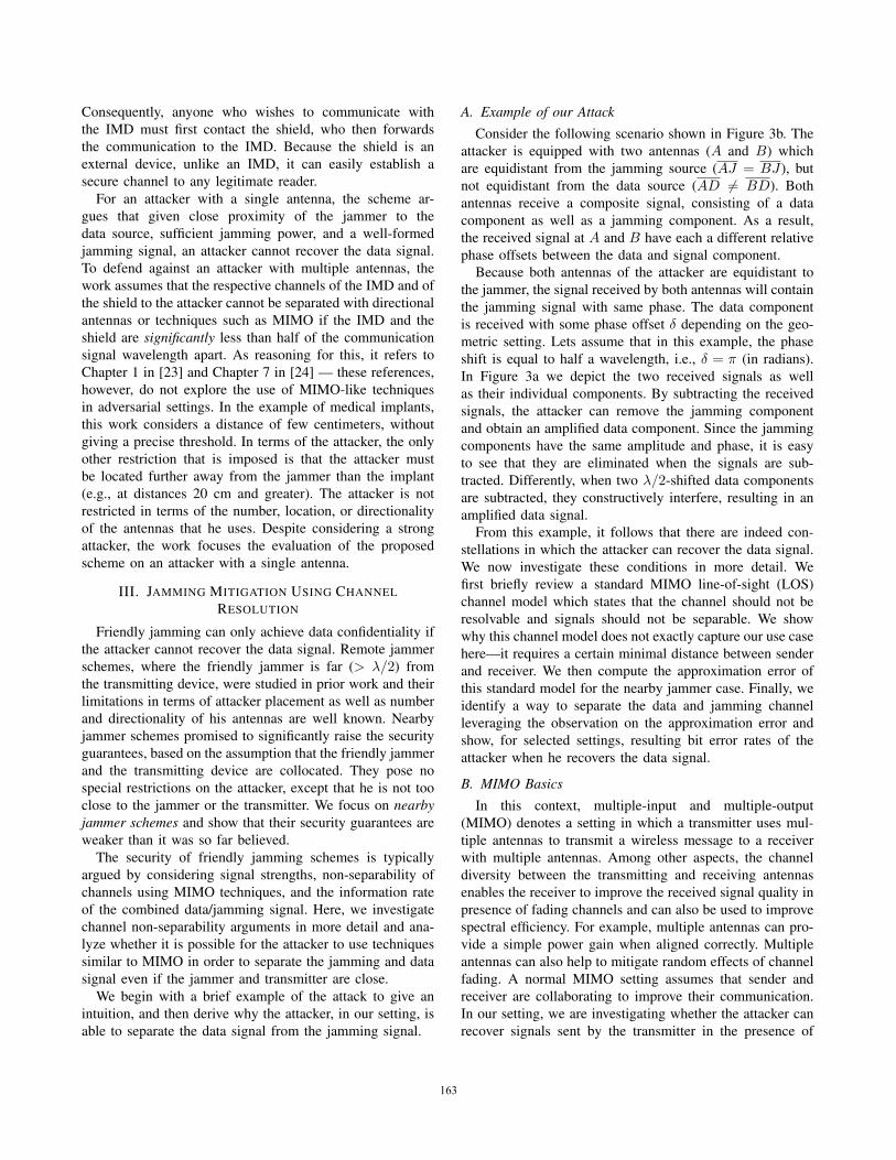
Figure 15. Bit error rates obtained by an attacker for various antennaorientations and positions when the data transmitting antenna D was placedinside a slab of meat to simulate NLOS conditions.
2) Effect of Jamming Signal’s Power: In the next set of
experiments, we fix the distance between the attacker and
D, J to 1m and vary the relative power of the jamming
signal w.r.t the data signal. The jammer is configured to
transmit at {20, 25, 30, 35} dB more than the power of the
data signal. Two sets of measurements with the jammer
placed at DJ = {15, 30} cm from the data transmitter is
taken. For all the measurements, the spacing between the
attacker antennas were fixed at AB = 50 cm. The results of
our experiments is shown in Figure 14(b). We observe that
for DJ = 30 cm, the attacker is able to recover 80% of the
data even with a relative jamming signal power of 30 dB.
However, for DJ = 15 cm, the bit error rate (BER) at the
attacker reaches almost 50%.
This shows that the jamming signal is not canceled
perfectly by the attacker. We estimate that this effect is due
to three possible sources of error: (i) imperfect alignment
of the jamming signals before cancellation, (ii) slightly
different channels for both receiving antennas in our real
world scenario, and (iii) uncorrelated receiving noise at the
receivers (the w we ignored earlier). Nevertheless, it can be
observed that our attack works in a number of scenarios.
3) For DJ � λ/2: In order to evaluate the attacker’s
effectiveness in separating the data from the jamming signal
when D and J are placed in very close proximity, we
experimented with DJ = 5 cm (i.e, DJ at-least an order
of magnitude less than λ). We observed BERs close to
50% at distances greater than 1m when using two omni-
directional antennas. However, with directional log-periodic
antennas [26] we were able to fully recover the data signal
from distances as far as 3m from DJ .
4) In NLOS Conditions: In this set of experiments, we
evaluate the ability of an attacker to recover messages in
scenarios where there is no LOS between the attacker and
the data transmitter. We simulated this setup by sandwiching
the data transmitting antenna (D) between 4 cm of ground
beef and a thin (1 cm) layer of bacon. Since there is no
restriction on the type of antenna an attacker can use, we
used directional log-periodic antennas for additional gain
and to minimize multipath channel effects. The attacker
antennas were placed at distances {0.5, 1, 2}m away from
D and J . The jamming signal was ensured to be at-least
20 dB more than the data signal. While our experimental
setup resembles the setting from [11], we note that there
are several differences. In particular, we use an USRP [27]
to generate the data signals instead of an IMD. In addition,
we use a different process to generate the spectrum-shaped
jamming signal.Figure 15 shows the BER observed at the attacker for
various orientations of attacker antennas A and B keeping
his distance d a fixed value. Even though the BER varies for
different orientations (which is expected due to non-static
channel conditions), the attacker was still able to recover
90% of the data in certain locations. This shows that there
are indeed constellations in space where the confidentiality
of data is breached under NLOS conditions. An exhaustive
analysis of effects of NLOS multipath channels on friendly
jamming schemes is left for future work.
V. DISCUSSION
In this section, we reflect on the results of the previous
sections and discuss possible extensions and related topics.
We start with the impact of medium BER attacks, discuss
the impact of multiple friendly jammers, possible counter-
measures, effects of SNR and multipath, and future work.
A. Placement of the AntennasSo far, we have not discussed how the attacker should
place his antennas to perform the attack. While finding
positions for A and B such that δ = π is easy in the
LOS setting without multipath, in real-world scenarios this
would require exact knowledge of channel conditions. Nev-
ertheless, we note that we were able to find good enough
placements for the antennas in our experiments relatively
easily, as the attacker can often still demodulate the data
signal with δ < π/2 and less. Our setting differs from
traditional benign communication scenarios in the sense that
it suffices for the attack to be successful some times, not
necessarily all the time. Also, unlike communication partners
in benign communication, we assume that the attacker can
afford to adapt the antenna placement for changing channel
conditions. This allows us to operate in more favorable
settings than the average fading channel. We also note that
the process of placing the antennas could be automated with
a mechanized antenna array, similar to [28].
B. Partial Information LeakageIn our simulation model and experiments we used BER as
an evaluation metric. While the consequences of a very low
170

BER (the attacker completely breaks confidentiality) and a
BER of 0.5 (confidentiality remains intact) at the attacker
are clear, we discuss the implications of partial information
leakage—for example, a BER of 0.2 at the attacker. In this
scenario, the attacker will successfully recover 80% of the
bits. In many cases, this leads to the attacker completely
breaking confidentiality, e.g., a patient’s name. In addition,
if the IMD sends the same data again (e.g. in a repeated
message), the attacker will be able to use this additional
information to recover the patient’s name, thus completely
breaking the system’s confidentiality.
C. Multiple Friendly Jammers
In this paper, we discussed friendly jamming schemes
that rely on a single jammer. This is a commonly used
system model when the goal is confidentiality, as the le-
gitimate receiver should be able to demodulate the data. In
most cases, the legitimate receiver also acts as the friendly
jammer. Schemes that use multiple jammers do not achieve
confidentiality of legitimate messages but are only able to
restrict unauthorized entities from using the communication
medium. To the best of our knowledge, the only scheme
which relies on multiple jammers for confidentiality is
one where the jammers form a “jamming fence” around a
protected area [15]. Nevertheless, in these settings, multiple
jammers are used to cover a greater area and not to improve
system’s confidentiality. Thus, these schemes assume that a
single jammer is enough to protect the confidentiality of the
messages. As such, we follow that our attack could also be
used to attack these proposals—at least for positions which
are only covered by a single jammer.
D. Countermeasures
From our analysis and experiments, we can draw several
conclusions on possible countermeasures against our attack.
While these do not guarantee complete confidentiality of
the system, they decrease the attacker’s probability of suc-
cess. In particular, our simulations and experimental results
underline the impact of close placement of J to D. As
we have shown, simply choosing DJ < λ/2 does not
prevent the attacker from receiving the data. Nevertheless,
the BER of the attacker rises with decreasing DJ . Therefore,
DJ should always be chosen to be as small as possible.
As λ depends on the carrier frequency, DJ must be be
smaller for higher frequencies to provide the same level
of protection. Therefore, sending data signals in the MICS
bands is easier to protect than, for example, IEEE 802.11
signals. In addition, we estimate that multiple jammers will
at least force the attacker to use more antennas for his
receiving array. As discussed before, the problem here is to
ensure that the intended receiver can still receive the message
despite the presence of multiple friendly jammers.
E. SNR and Multipath Effects
In our simulations while computing BER, we assume a
certain SNR at the attacker in the absence of the jammer.
This is because a performance evaluation of our attack
only makes sense if the attacker can receive the message
in the absence of a friendly jammer. For our simulations,
our estimations of the SNR at the attacker was 16 dB. The
attacker can improve his SNR by using better receiving
equipment (e.g. low noise amplifiers, better ADC, high-gain
antennas etc.). This would even improve the efficiency of
our attacks.
Another important factor affecting the performance of
our attacks are the multipath effects. In our analysis, we
concentrate on modeling line-of-sight channels. In practice,
multipath effects can degrade the performance of our at-
tack by introducing additional phase shifts or signal fading
effects. Nevertheless, our experiments, conducted in real-
world settings under the influence of multipath effects, still
yield realistic attacker scenarios. However, the performance
for non line-of-sight scenarios needs to be further explored.
It is to be expected that in the worst case, the attacker still
has a probabilistic chance of randomly being at a correct
position for his attack (similar to malicious interference
attacks in [29]).
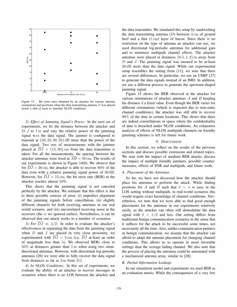
F. Effect of Signal Bandwidth and Modulation Scheme
We noted earlier that higher signal bandwidth results in a
more distorted reconstructed data signal.
To understand the effects of signal bandwidth on our
proposed attack, we consider the ratio r = β/fc of data
signal bandwidth β and its carrier frequency fc. While
for MICS signals this ratio is around 0.00075, in UWB
communications r could approach 0.25. The ratio directly
relates to the length of a baseband symbol, expressed in
carrier periods. In our presented cancellation scheme, the
two data components are subtracted with some phase shift,
ideally λ/2. For signals with very low bandwidth, adding a
λ/2-shifted version of itself completely cancels the signal
and subtracting it almost doubles the amplitude. For signals
with higher bandwidth, subtracting a λ/2-shifted version
will not completely cancel the signal, since the amplitudes
of the carrier will change considerably with each period.
Intuitively, with lower signal bandwidth, the signal is more
similar to its λ/2-shifted version, and thus the cancellation
(or amplification) will be better. Figure 16 shows how
different values of r affect the cancellation rate.
In this work we focused on low-bandwidth FSK as modu-
lation scheme. We leave the evaluation of other modulations
schemes (e.g. high bandwidth UWB signals) for future work.
G. Jamming for Access Control
Throughout the paper we focused on jamming for confi-
dentiality. Jamming can also be used for achieving access
control, i.e., using friendly jamming in order to deny access
171
����������� �� ������ ���� ������ ��
�
�
�
�
��
� �� �
Figure 16. Effect of the ratio between bandwidth and carrier frequency r = β/fc on cancellation effectiveness. Cancellation effect is larger for smallervalues of r.
to a protected device. Existing schemes implement one of
the following jammer classes.
• Fast jammer. A friendly jammer demodulates signals
intended for the protected device in real-time. Upon de-
modulating and inspecting parts of the frame, a choice
is made whether or not the frame is allowed. In case the
frame does not conform to a pre-defined access control
policy, the remaining portion of the frame will be
jammed. Such a strategy prevents the protected device
from successfully demodulating a complete adversarial
query.
• Slow jammer. The friendly jammer listens for mes-
sages destined for the protected device but does not start
jamming in mid-frame. The jammer receives the whole
frame and, in case the access control policy is violated,
starts jamming the reply of the protected device.
Xu et al. propose a scheme for securing IMD devices
against access from unauthorized sources [12]. Security is
enforced by a specialized device which employs friendly
jamming—the Guardian. The authors argue it is more re-
liable and effective to let the Guardian jam replies by the
IMD, instead of directly jamming query messages issued
by the attacker. The Guardian device can effectively set it’s
own jamming parameters because it knows the transmission
power and reply timing information of the protected IMD.
Rieback et al. proposed the concept of selective RFID
jamming to enforce access control of RFID tags [8], [9].
An external friendly jammer listens for queries towards
protected RFID tags. If the query is not allowed, based on
an access control policy, the tag reply is jammed.
The above works jam replies made by the protected
device, but not adversarial queries—they implement the slowjammer approach.
Martinovic et al. proposed a scheme based on a fast
jammer. The authors use the concept of friendly jamming in
sensor networks to enforce access control by jamming unau-
thenticated frames in mid-air [10]. The proposed scheme
prevents protected devices from successfully demodulating
unauthorized queries, i.e., it implements the fast jammer
approach.
Our proposed attack can be used against access control
schemes which implement the slow jammer approach. An
adversary can mount an active attack by sending unsanc-
tioned queries to protected devices. Friendly jammers detect
such queries and jam device replies. However, our scheme
is then used to remove the jamming component from the
reply. By doing so, an adversary is able to bypass the access
control policy and communicate with the protected device
in the same way as if a friendly jammer was not present.
VI. CONCLUSION
In this work, we revisit the confidentiality guarantees
provided by friendly jamming schemes. We focused on the
assumption that the attacker cannot recover the confidential
message if the friendly jammer and the message source
are in close proximity. We showed, both analytically and
experimentally, that this assumption does not hold. In our
experiments, performed in the MICS band, we demonstrated
the successful recovery of confidential messages from up
to 3m away, when a friendly jammer and the source were
placed only few centimeters apart. Our results show that
friendly jamming schemes have some fundamental security
limitations when they are used to achieve confidentiality.
VII. ACKNOWLEDGMENTS
This work was funded by the Swiss National Science
Foundation (SNSF) under the grant 200020 129605.
REFERENCES
[1] R. Negi and S. Goel, “Secret communication using artificialnoise,” in IEEE Vehicular Technology Conference, 2005.
[2] S. Goel and R. Negi, “Guaranteeing secrecy using artifi-cial noise,” IEEE Transactions on Wireless Communications,vol. 7, no. 6, pp. 2180–2189, 2008.
[3] A. Araujo, J. Blesa, E. Romero, and O. Nieto-Taladriz, “Co-operative jam technique to increase physical-layer securityin CWSN,” in COCORA 2012, The Second InternationalConference on Advances in Cognitive Radio, 2012, pp. 11–14.
172

[4] L. Dong, Z. Han, A. Petropulu, and H. Poor, “Cooperativejamming for wireless physical layer security,” in Proceedingof IEEE Workshop on Statistical Signal Processing (SSP), sept2009, pp. 417–420.
[5] X. Tang, R. Liu, P. Spasojevic and, and H. Poor, “Interferenceassisted secret communication,” IEEE Transactions on Infor-mation Theory, vol. 57, no. 5, pp. 3153 –3167, May 2011.
[6] J. Vilela, M. Bloch, J. Barros, and S. McLaughlin, “Friendlyjamming for wireless secrecy,” in Proceedings of the IEEEInternational Conference on Communications (ICC). IEEE,2010, pp. 1–6.
[7] ——, “Wireless secrecy regions with friendly jamming,”Information Forensics and Security, IEEE Transactions on,vol. 6, no. 2, pp. 256 –266, june 2011.
[8] M. R. Rieback, B. Crispo, and A. S. Tanenbaum, “Keep onblockin’ in the free world: Personal access control for low-cost RFID tags,” in Proc. 13th International Workshop onSecurity Protocols. LNCS, Apr 2005.
[9] ——, “RFID guardian: A battery-powered mobile devicefor RFID privacy management,” in Proc. 10th AustralasianConf. on Information Security and Privacy (ACISP 2005), ser.LNCS, vol. 3574. Springer-Verlag, July 2005, pp. 184–194.
[10] I. Martinovic, P. Pichota, and J. Schmitt, “Jamming forgood: A fresh approach to authentic communication in wsns,”in Proceedings of the second ACM conference on Wirelessnetwork security. ACM, 2009, pp. 161–168.
[11] S. Gollakota, H. Hassanieh, B. Ransford, D. Katabi, andK. Fu, “They can hear your heartbeats: Non-invasive securityfor implanted medical devices,” in Proceedings of the ACMSIGCOMM Conference, August 2011.
[12] F. Xu, Z. Qin, C. Tan, B. Wang, and Q. Li, “Imdguard: Secur-ing implantable medical devices with the external wearableguardian,” in INFOCOM, 2011 Proceedings IEEE. IEEE,2011, pp. 1862–1870.
[13] M. Wilhelm, I. Martinovic, J. B. Schmitt, and V. Lenders,“WiFire: a firewall for wireless networks,” in Proceedings ofthe ACM SIGCOMM Conference, 2011, pp. 456–457.
[14] C. Kuo, M. Luk, R. Negi, and A. Perrig, “Message-in-a-bottle:user-friendly and secure key deployment for sensor nodes,” inProceedings of the 5th international conference on Embeddednetworked sensor systems. ACM, 2007, pp. 233–246.
[15] S. Sankararaman, K. Abu-Affash, A. Efrat, S. D. Eriksson-Bique, V. Polishchuk, S. Ramasubramanian, and M. Segal,“Optimization schemes for protective jamming,” in Proceed-ings of the ACM International Symposium on Mobile Ad HocNetworking and Computing (MobiHoc), 2012, pp. 65–74.
[16] H. Al-Hassanieh, “Encryption on the air: non-invasive se-curity for implantable medical devices,” Ph.D. dissertation,Citeseer, 2011.
[17] A. Molisch, Wireless Communications. Wiley, 2011.
[18] S. Leung-Yan-Cheong and M. Hellman, “The gaussian wire-tap channel,” Information Theory, IEEE Transactions on,vol. 24, no. 4, pp. 451–456, 1978.
[19] X. Zhou and M. McKay, “Physical layer security with arti-ficial noise: Secrecy capacity and optimal power allocation,”in International Conference on Signal Processing and Com-munication Systems (ICSPCS). IEEE, 2009, pp. 1–5.
[20] O. Koyluoglu and H. El Gamal, “On the secrecy rate regionfor the interference channel,” in Proceedings of the Inter-national Symposium on Personal, Indoor and Mobile RadioCommunications (PIMRC). IEEE, 2008, pp. 1–5.
[21] S. Goel and R. Negi, “Secret communication in presence ofcolluding eavesdroppers,” in Proceedings of the IEEE MilitaryCommunications Conference (MILCOM), 2005, pp. 1–6.
[22] P. Pinto, J. Barros, and M. Win, “Wireless physical-layer se-curity: The case of colluding eavesdroppers,” in Proceedingsof the IEEE International Symposium on Information Theory(ISIT), 2009, pp. 2442–2446.
[23] W. Jakes, Microwave mobile communications, ser. IEEE Pressclassic reissue. IEEE Press, 1974.
[24] D. Tse and P. Viswanath, Fundamentals of wireless commu-nication. New York, NY, USA: Cambridge University Press,2005.
[25] “Matlab – a numerical computing environment,”The MathWorks, Inc; www.mathworks.com.
[26] Ettus, “Log periodic pcb directional antenna,”https://www.ettus.com/product/details/LP0410.
[27] ——, “Universal software radio peripheral (USRP),”http://www.ettus.com.
[28] T. Vo-Huu, E.-O. Blass, and G. Noubir, “Counter-jammingusing mixed mechanical and software interference cancella-tion,” in Proceedings of the ACM conference on Security andPrivacy in Wireless and Mobile Networks, 2013.
[29] C. Popper, N. O. Tippenhauer, B. Danev, and S. Capkun,“Investigation of signal and message manipulations on thewireless channel,” in Proceedings of the European Symposiumon Research in Computer Security, 2011.
173