on legalization of row-based placements andrew b. kahngsherief reda cse & ece departments...
Post on 21-Dec-2015
213 views
TRANSCRIPT

On Legalization of Row-Based Placements
Andrew B. Kahng Sherief RedaCSE & ECE Departments
University of CA, San DiegoLa Jolla, CA [email protected]
CSE DepartmentUniversity of CA, San Diego
La Jolla, CA [email protected]
Igor L. MarkovEECS Department
University of MichiganAnn Arbor, MI 48109
VLSI CAD Laboratory at UCSD

Outline
Introduction and Previous Work
Legalization Objectives
Legalization Method
Experimental Results
Conclusions

Introduction: Objectives Used in Legalization
An Illegal Placement due to Overlaps
Overlap may be due: buffer insertion, gate sizing, etc
Overlap must be removed, sample objectives include minimizing:
(i) Total distance moved, i.e., total perturbations(ii) Total increase in HPWL (wirelength)(iii) The maximum distance moved by a cell
Overlap
cell
row
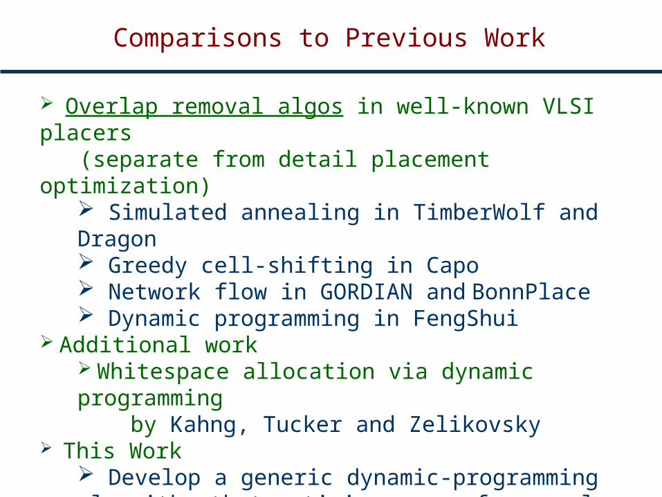
Comparisons to Previous Work
Overlap removal algos in well-known VLSI placers (separate from detail placement optimization)
Simulated annealing in TimberWolf and Dragon Greedy cell-shifting in Capo Network flow in GORDIAN and BonnPlace Dynamic programming in FengShui
Additional work Whitespace allocation via dynamic programming by Kahng, Tucker and Zelikovsky
This Work Develop a generic dynamic-programming algorithm that optimizes one of several objectives Study the effect of the objective choice on total wirelength and routability

Outline
Introduction and previous work
Legalization Objectives
Legalization Method
Experimental Results
Conclusions
Overview of the Legalization Procedure
We propose a two-phase approach for overlap removal:
Phase I: Juggle cells to meet row capacity constraints.
Phase II: Remove the overlaps within each row using a generic dynamic-programming approach according to a number of objectives.

Phase I: Cell Juggling
Juggle cells to meet row capacity constraints by moving cells from over-capacity rows to under-capacity rows.
Under-capacity rows
Over-capacity rows
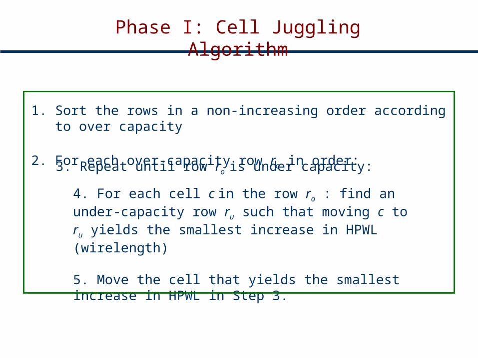
Phase I: Cell Juggling Algorithm
1. Sort the rows in a non-increasing order according to over capacity
2. For each over-capacity row ro in order:
3. Repeat until row ro is under capacity:
4. For each cell c in the row ro : find an under-capacity row ru such that moving c to ru yields the smallest increase in HPWL (wirelength)
5. Move the cell that yields the smallest increase in HPWL in Step 3.
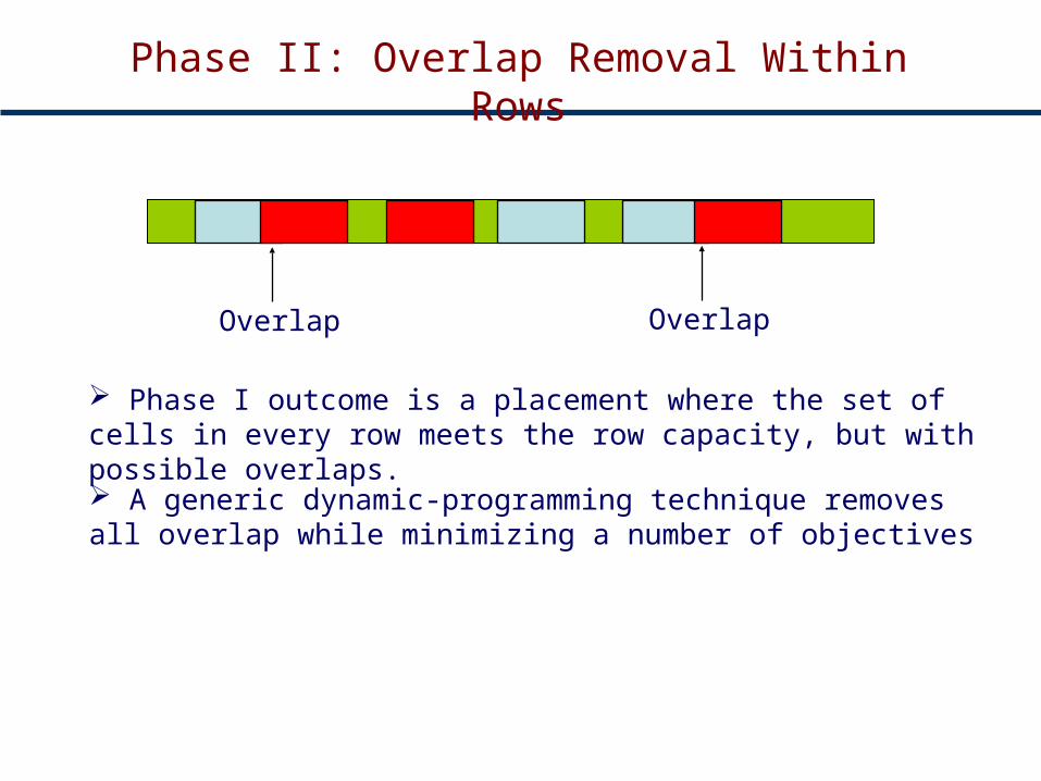
Phase II: Overlap Removal Within Rows
Overlap Overlap
A generic dynamic-programming technique removes all overlap while minimizing a number of objectives
Phase I outcome is a placement where the set of cells in every row meets the row capacity, but with possible overlaps.

Each chain represents the possible sites that a cell can be placed at
The order of chains correspond to the order of cells from left to right in a row
Overlap Removal Using Dynamic Programming
sites
cell 1
cell 2
cell 3
cell n
row
1 2 3 4 5 6 7 8 9 10 11 12start node
end node

Start and end sitesSites that cell will be placed atEmpty sites
Sites not included in calculation
There are many paths from the start and end nodes → select the one that optimizes one of our objectives
Overlap Removal Using Dynamic Programming
sites
cell 1
cell 2
cell 3
cell n
row 1 2
1 2 3 4 5 6 7 8 9 10 11 12

Min Total Distance Overlap Removal
1. Label a diagonal edge starting at some column j and chain c by the difference in distance between j and current location of cell c.
2. Label all horizontal edges by cost 0
3. Find the shortest path from start to end nodes using lexicographical sorting.
row c
2 1 10 2 3 4 5 6 7 8 9
12 0 1 2 3 4 5 6 7 8
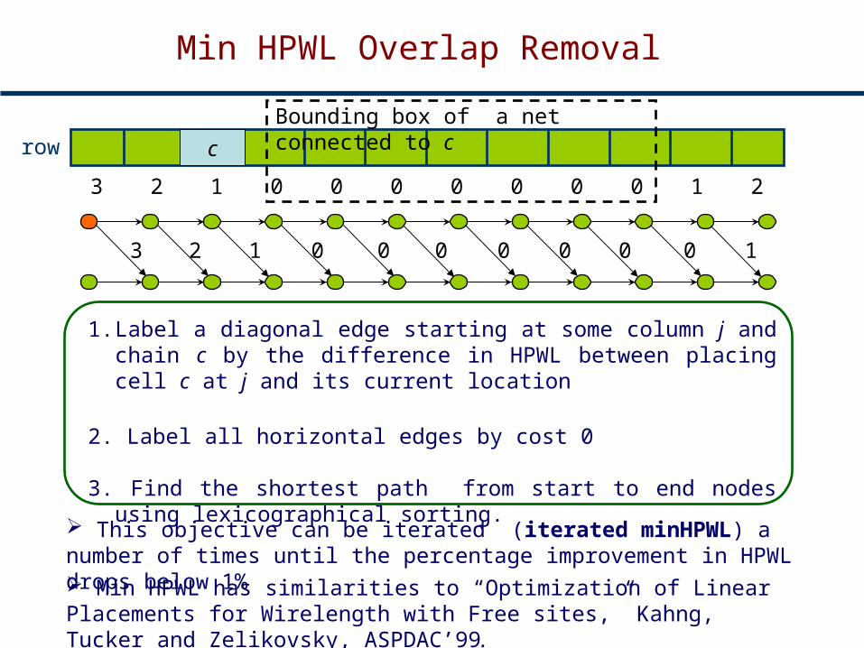
Min HPWL Overlap Removal
row c
3 2 01 0 0 0 0 0 0 1 2
23 1 0 0 0 0 0 0 0 1
1. Label a diagonal edge starting at some column j and chain c by the difference in HPWL between placing cell c at j and its current location
2. Label all horizontal edges by cost 0
3. Find the shortest path from start to end nodes using lexicographical sorting.
This objective can be iterated (iterated minHPWL) a number of times until the percentage improvement in HPWL drops below 1%
Bounding box of a net connected to c
Min HPWL has similarities to “Optimization of Linear Placements for Wirelength with Free sites,” Kahng, Tucker and Zelikovsky, ASPDAC’99.
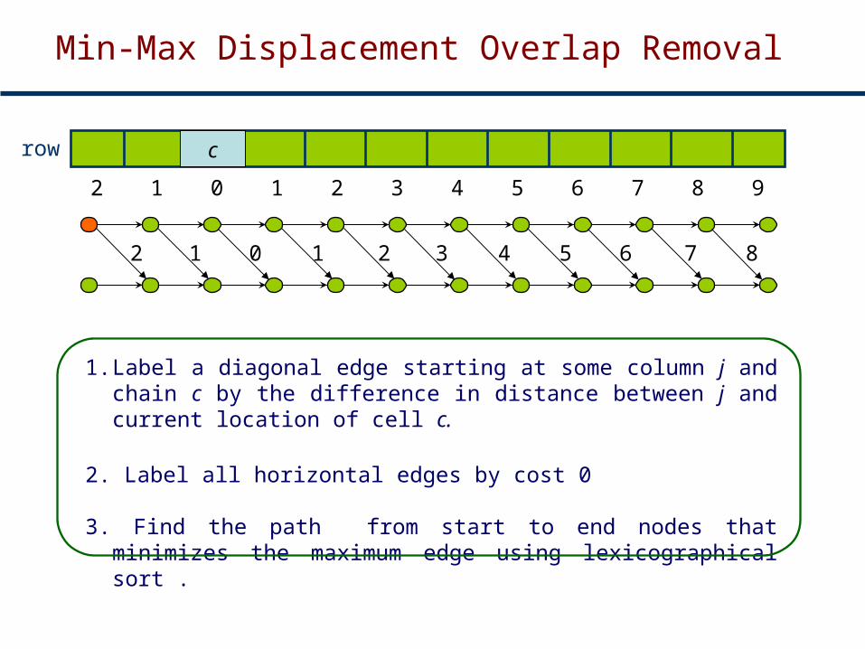
1. Label a diagonal edge starting at some column j and chain c by the difference in distance between j and current location of cell c.
2. Label all horizontal edges by cost 0
3. Find the path from start to end nodes that minimizes the maximum edge using lexicographical sort .
row c
2 1 10 2 3 4 5 6 7 8 9
12 0 1 2 3 4 5 6 7 8
Min-Max Displacement Overlap Removal

Outline
Introduction and Previous Work
Legalization Objectives
Legalization Method
Experimental Results
Conclusions

Experimental Results (IBM01)
Mode Overlaps HPWL Runtime(s) Impr (%)
ibm01 Capo illegal 964 5.517 -
Capo legalizer
0 5.586 -
QPlace –eco 0 5.639 1.0
min HPWL 0 5.519 6.9 2.13%
min Dist 0 5.623 1.3 0.28%
min-max Disp 0 5.699 1.3 -1.06%
Iterated minHPWL
0 5.462 39.1 3.14%
Improvement percentage is relative to QPlace -eco
We execute Capo (without its built-in legalizer) + Legalizer
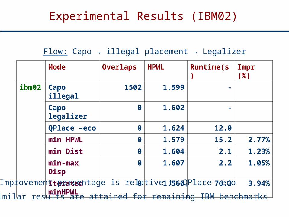
Mode Overlaps HPWL Runtime(s) Impr (%)
ibm02 Capo illegal 1502 1.599 -
Capo legalizer
0 1.602 -
QPlace –eco 0 1.624 12.0
min HPWL 0 1.579 15.2 2.77%
min Dist 0 1.604 2.1 1.23%
min-max Disp 0 1.607 2.2 1.05%
Iterated minHPWL
0 1.560 76.3 3.94%
Improvement percentage is relative to QPlace -eco
Experimental Results (IBM02)
Flow: Capo → illegal placement → Legalizer
Similar results are attained for remaining IBM benchmarks

Experimental Results
benchmark Objective HPWL Global Routing Metrics Violations
Overtrack Overcapacity
ibm01 min-max disp
5.773 4489 3755 11743
min dist 5.846 4489 3755 11743
minHPWL 5.625 4616 3799 12602
The min dist and min-max dist objectives attempt to preserve the whitespace map → preserves routability
Min HPWL objective optimizes wirelength, but may alter the whitespace map
Flow: Capo → illegal placement → Legalizer → Cadence’s WarpRoute
Conclusions
A generic dynamic-programming that handles a number of legalization objectives:
A two-phase legalizer is proposed
Minimum-total displacement Minimum-total HPWL Minimum-Max displacement
The effect of various objectives on routability and wirelength are evaluated
The effect of cut directions on the amount of overlap is studied

Thanks
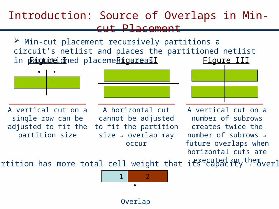
Introduction: Source of Overlaps in Min-cut Placement
A vertical cut on a single row can be adjusted to fit
the partition size
A horizontal cut cannot be adjusted to fit the partition size → overlap may occur
A vertical cut on a number of subrows creates twice the number of subrows →
future overlaps when horizontal cuts are executed on them
1 2
If a partition has more total cell weight that its capacity → overlap occurs
Overlap
Figure I Figure II Figure III
Min-cut placement recursively partitions a circuit’s netlist and places the partitioned netlist in partitioned placement areas

Effect of Cut-Sequence on Amount of Overlaps
Relationship between number of vertical cuts, total Wirelength, and number of overlaps.
Vertical cuts on a number of rows are the main reason for overlaps in min-cut placement