on database eeri - ieee computer societysites.computer.org/debull/83jun-cd.pdf · june1983 vol.6...
TRANSCRIPT
JUNE1983 VOL.6 No.2
a quarterly bulletin
of the IEEE computer societytechnical committee
on
Databaseeeri
Contents
Letter from the Editor
The Auragen System 4000 3
R. Gostanian
Transaction Processing in the PEFRPOS
Operating System 9
J.C. West, MA. Isman, and S.G. Hannaford
A Fault-Tolerant Transaction ProcessingEnvironment 20
P.S. Kastner
The Synapse Approach to High Systemand Database Availability 29
S.E. Jones
A Highly Reliable System for Distributed
Word Processing 35
NB. Cohen, S. Henderson, C. Won
Database Management Strategies to
Support Network Services 42
D. Cohen, J.E. Holcomb, MB. Sury
Experience with a Large Distributed
Banking System 50
J. Robert Good
Distributed Database Support 57
I. Aaro and J.G. Holland
Distributed Data Management Issues
in the LOCUS System 63
G.J. Popek and G. Thiel
Research in Database Programming:
Language Constructs and Execution
Models 68
J.W. Schmidt, M. Reimer, P. Putfarken, M. Mall,
J. Koch, and M. Jarke

Chairperson, Technical Committee
on Database Engineering
Professor P. Bruce Berra
Dept. ot Electrical and
Computer Engineering111 Link Hall
Syracuse University
Syracuse, New York 13210
(315) 423-2655
Editor-in-Chief,
Database Engineering
Dr Won Kim
IBM Research
K54-282
5600 Cotile Road
San Jose, Calif 95193
(4081 256-1507
Associate Editors,
Database Engineering
Prof Don Batory
Dept. of Computer and
Information Sciences
University of Florida
Gainesville, Florida 32611
19041 392-5241
Prof Alan Hevner
College of Business and Management
University of Maryland
College Park, Maryland 20742
(3011454-6258
Dr David Reiner
Sperry Research Center
100 North Road
Sudbury, Mass 01776
(6171 369-4000 x353
Prof Randy Katz
Dept of Computer Science
University of Wisconsin
Madison, Wisconsin 53706
(6081 262-0664
Dr. Dan Ries
Computer Corporation of America
4 Cambridge Center
Cambridge, Massachusetts 02142
(617) 492-8860
International Advisors,
Database Engineering
Prof. Francois Banciihon
1NRIA
Domaine de Voluceau—ROCQUENCOURT
B.P. 105—7B153 LE CHESNAY CEDEX
France
Prof. Stefano Ceri
Diparfimento di Elettronica,
Politecnico di Milano
P. za L. Da Vinci 32. 20133
Milano, Italy
Prof. Yoshifumi Masunaga
University of Information Science
Yatabe-Machi, Ibaragi-ken, 305, Japan
Prof. Daniel Menasce
Department of Information Science
Pontificia Universidade Catolica
Rue Marques de Sao Vicenfe
225-CEP 22453 Rio de Janeiro
Brazil
Database Engineering Bulletin is a quarterly pubhcationof the IEEE Computer Society Technical Committee on
Database Engineering. Its scope of interest includes: data
structures and models. access strategies. access control
techniques. database architecture, database machines.
intelligent front ends, mass storage for very large data
bases. distributed database systems and techniques.database software design and implementation, database
utilities, database security and related areas.
Contribution to the Bulletin is hereby solicited. News
items. letters. technical papers. book reviews, meetingpreviews, summaries, case studies. etc.. should be sent
to the Editor. All letters to the Editor will be considered for
publication unless accompanied by a request to the con
trary. Technical papers are unrefereed.
Opinions expressed in contributions are those of the indi
vidual author rather than the official position of the IC on
Database Engineering, the IEEE Computer Society. or
organizations with which the author may be affiliated.
Membership In the Database Engineering Technical
Committee is open to individuals who demonstrate willingness to actively participate in the various activities ot the
TC A member of the IEEE Computer Society may loin the
TC as a full member. A non-member of the Computer
Society may join as a participating member, with approvalfrom at least one officer of the TO. Both a full member and
a participating member of the IC is entitled to receive the
quarterly bulletin of the TO free of charge. until further
notice.
Membership applications and requests for back issues
should be sent to IEEE Computer Society. P0, Box 639,
Silver Spring, MD 20901. Papers and comments on the
technical contents of Database Engineering should be
directed to any of the editors.

Letter from ~ Edit~
This issue of Database Engineering focuses on highlyavailable systems. The first five articles are from com
mercial vendors who market fault—tolerant computer systems. The next three articles describe specific systemsthat were built for applications which required a highdegree of availability. The final article on this topicpresents some new research directions for maintaining system availability. This issue also includes one generalinterest paper from Germany on database programminglanguages.
More and more end users of automatic teller windows,on—line reservation systems, and word processors are
becoming dependent on the continuous availability ofinteractive computer systems. System failures, which can
shut down these or other applications, thus have an
increasing impact on the day to day operations of bothcompanies and individuals. Tandem Computers Incorporatedrecognizing the serious impact of such failures has been a
pioneer in the development of fault—tolerant systems. (Anoverview of the Tandem’s approach to fault—tolerance can
be found in the December 1983 issue of Database Engineer.jjig and is not repreated in this issue.)
Since Tandem’s success, numerous other companies are
developing fault—tolerant hardware and software systems.This issue contains overviews of the systems provided byAuragen, Computer Consoles, Stratus, Synapse, and Syntrex.Each article describes a different architecture and
operating system approach to maintaining high availability. The articles also describe how specific types offailures are handled.
The next three papers describe how high availabilityis maintained for specific distributed applications. A
paper from Bell Labs describes the redundancy and transaction processing of a system to support the Direct Services
Dialing Capability. A paper from Bank of Americadescribes a large bank teller support system and presentssome impressive availability statistics. A paper fromPhilips Data Systems then describes the transactionmechanisms they support to allow continuous processingeven though some of the updates have to be delayed.
The final paper, from UCLA, describes how the reliability and thus availability of systems can be increased
through direct operating system management. of distributedand replicated name spaces and general distributed transaction mechanisms.
1

I would like to thank the contributors to this issue.It is clear that there are many approaches to increasingsystem availability. I suspect that sometime in the nottoo distant future continous operations in the presence ofa small number of failures will become the norm of what isexpected from computer systems. I trust that the readerswill find the overviews of the different approaches as
interesting and informative as I have.
Future Issues
Database Engineering will continue to devote eachissue to a special topic. The topics of the next fourissues are described below:
1. Expert Systems. Dr. Adrian Walker (IBM Research, San
Jose) is the Guest Editor for the September issue.
2. Automated Office Systems. Prof. Fred Lochovsky (visitor at IBM Research, San Jose from the University ofToronto) is the Guest Editor of the December issue.Submission Deadline is August 1.
3. Statistical Database Management. Prof. Don Batorywill be the editor of the March, 1984 issue. Submission deadline is November 1.
4. Engineering Design Databases. Prof. Randy Katz willbe the editor in charge of the June, 1984 issue onthis topic. Submission deadline is February 1.
Papers relevant to these special topics should be submitted to the editor in charge of that issue and to Dr. WonKim, our Editor—in—Chief. As space is available we willalso accept a few general interest papers for each issue.These papers should be sent directly to Dr. Kim.
Daniel R. Ries
2

The Auragen System 4000
Richard Gostanian
Auragen Systems CorporationTwo Executive Drive, Fort Lee, NJ 07024 (201) 461—3400
The Auragen System 4000 is an expandable, fault—tolerant multi—
micro—processor designed to provide a foundation for a wide varietyof high availability applications in the transaction processing,comunications and office automation arenas. The wide applicabilityof the system is due to a combination of a novel architecture, the
implementation of a highly enhanced version of the UNIX operating
system, the addition of a full—function relational database manage
ment system and the inclusion of a rich complement of productivitytools and user—oriented application development aids.
Detailed discussions of each of these features can be found in
1]. Our purpose in this note is to briefly describe the most im
portant aspects of the Auragen approach to fault—tolerance.
I. Fault—Tolerant Design Goals
The essential ingredient of all fault—tolerance is redundancy——in both hardware and software. The amount of redundancy, and where
to employ the redundancy, is largely determined by the number and
the types of failures to which the system is designed to be immune.
In general, failures come in three flavors:
a) permanent physical failures such as shorted connectors,
burnt out chips, etc.
b) transient component failures due chiefly to temporaryenvironmental disturbances, and
c) operational mishaps such as data entry errors, the use
of erroneous software, etc.
Failures of type c) are the hardest to deal with and are best
handled by software. The easiest case is when mishaps occur in con
nection with the storage and retrieval of information from largefiles. Here there are a number of well—known recovery techniques,
involving the use of redo and undo logs, which have proved to be
quite robust, and require no special hardware to implement. Vari
ations on such techniques have been incorporated into AURALATE,the Auragen relational D~MS~ and wUl be discussed later. Unf-~ortun—
atly, however, the general problem of providing automatic recovery
from operational mishaps is very difficult to deal with in a syste
matic manner, and really falls outside the realm of fault—tolerant
computing as practised today.
Instead, designers of fault—tolerant computer architectures have
UNIX is a trademark of Bell Laboratories
3

sought largely to cope with physical failures. In the case of the
Auragen system, the main goal has been to produce a machine with
continuous, or nearly continuous, availibility despite the inevi
table occurances of physical failures. This goal has been achieved
by designing an architecture which
1) provides survivability through any single hardware
failure,2) enables users to repair failures (i.e. change faulty
boards) while the system is running and
3) enables users or field engineers to expand and recon
figure a system without having to shutdown and subse
quently sysgen again.
Except for possibly the requirement that users be able to repairand reconfigure systems themselves, none of these features are new;
what is new is the ways in which they have been implemented.
II. Hardware Organization
An Auragen system is a loosely coupled configuration of between
2 and 32 clusters, interconnected by two 16 megabyte/sec shared
buses. Under normal circumstances, in the absence of a bus failure,the two buses behave as a single 32 megabyte/sec bus.
The clusters themselves are tightly coupled multiprocessors con
sisting of their own memory, power supply, battery backup, several
different kinds of intelligent I/O controllers and 3 MC68000’s. One
of the 68000’s is used exclusively for performing operating system
functions, while the other two are used to process user tasks. All
peripherals are dual ported and are always attached to two separateclusters —— although peripherals need not be attached to each clus
ter. Discs, which have higher survivability requirements than other
peripherals, may optionally be configured to operate in mirrored
pairs.
This organization has enough hardware redundancy within a two
cluster system so as to be able to continue operating after any
single hardware failure. Systems with three or more clusters can
survive some types of multiple hardware failures.
III. Operating System Support
The Auragen operating system, AUROS, is a significant enhance
ment of UNIX System III. From the outside, it looks exactly like
a superset of System III, in that it supports all the standard UNIX
facilities and interfaces, in addition to some new and very user
friendly capabilities at the command level.
Internally however it is entirely different from System III.
Among the many enhancements are
a) a demand paged virtual memory system allowing virtual
addressing up to 32 Mbytes per process,
4

b) extensive interprocess communication facilities employ
ing both messages and shared memory,
c) a distributed process structure In which all I/O
services have been split off, from the kernel and
placed into separate server processes for mulitprocess—
ing efficency,d) automatic load balancing among clusters, and
e) a fault—tolerant mode of operation based on the automa
tic creation of backup processes in foreign clusters.
This last feature, which is described more fully in the next sec
tion is what gives the Auragen system its unique character in the
fault—tolerant marketplace. Indeed, because fault—tolerance is im
plemented at a very low level,
i.e. entirely within the AUROS ker
nel, any program which will run under UNIX System III, will run on
the Auragen system in a completely fault tolerant fashion —— with
out any special action on the part of the user.
IV. Fault—Tolerant Implementation
Prior to the mid 1970’s, virtually all fault—tolerant computers
employed duplicate components, either as standby spare parts, or in
a majority voting type of configuration, whereby the duplicate com
ponents would simultaneously replicate each other’s actions. The
types of machines built using these early approaches were invariab
ly special purpose systems intended mostly for military, space and
telephone switching applications. The major disadvantage of such
designs was one of cost; at least three or four times the number of
components needed to build an equivalent non—fault—tolerant ma
chine were required to build one of these systems —— but unfor
tunately no extra computing power could be derived from the duplicate components.
In the mid 70’s, Tandem Computers 2] pioneered an approach to
fault—tolerance which partially solved the problem of wasted duplicate resources. The Tandem design, which was aimed specifically at
the commercial transaction processing market, involved creating an
inactive process, P—bak, for each active process P. P and P—bak
would live in different processors, so that if a failure should oc
cur In P’s processor, P—bak would immediately be activated in its
processor. Since, in the absence of failures, P—bak does not exe
cute, this scheme allows all the duplicate hardware to be used for
non—redundant work most of the time.
The Auragen design began with the conviction that the- Tandem ~ap—
proch was the most cost effective of all approaches to fault—toler
ance, but that the Tandem implementation was less than optimal in
at least two ways.
First, the data portion of P—bak had to be kept almost exactly
up to date with P’s data space. This was done by having P send a
“checkpoint” message to P—bak everytime P did an I/O. AlthoughP—bak did no processing upon receipt of the checkpoint message, a
5

very significant amount of message traffic, and thus processor
activity, was generated in the process of handling the checkpoint—
ing mechanism.
The second shortcoming of the Tandem approach was that the crea
tion and awareness of P—bak, as well as the sending of the check—
pointing messages, was entirely the responsibility of the program
mer. This made the writing and testing of fault—tolerant programs
significantly more difficult than the development of non—fault—
tolerant applications. Tandem recently remedied this situation
somewhat by providing tools which would automatically do the
checkpointing for the programmer. Those tools however, are quite
disappointing in that they only handle a limited class of applica—
tons, and their use generates significantly more checkpointingoverhead than the amount which would be generated by a clever pro
grammer doing his own checkpointing.
To remove these two shortcomings, Auragen developed a technique
strongly analogous to the roliforward type of recovery employed
by many database management systems. A full description of the
method is given in 3], but the basic ideas are as follows. Instead
of having P checkpoint its data space at the occurance of every
I/O, AUROS arranges to have all messages received by P simultan
eously deposited in a message queue at P—bak. Only after P has
processed some system defined number of messages will P—bak’s data
space be synchronized with that of P. After the synchronizationis complete, all the messages queued at P—bak are discarded and
the whole process is repeated.
If a failure should occur which causes the activation of P—bak,then P—bak will begin execution at the point of its last synchronization. Since the message queue at P—bak contains all the messages
sent to P —— between the time of the last synchronization and the
failure —— P—bak can easily redo all the work done by P within
that interval, and continue on from there. Of course some care has
to be taken during the rollforward phase to insure that P—bak
does not redo any work which P has done that is already reflected
somewhere else in the system. A clever technique to handle this has
been devised, and Is fully described in 3].
The whole procedure of queuing messages, synchronizing the
P—bak’s with the P’s and initiating recovery upon fault detection
is entirely handled by AUROS. Fault detection Itself is Implementedby a variety of hardware and software methods. These include parity
checking, power level monitors, watchdog timers, background diagnostics and very careful checking of system call parameters.
The scheme of having a completely inactive P—bak, Infrequently
synchronized with P, clearly trades off a somewhat longer recovery
time —— 5 to 10 secoonds on a system—wide basis —— for significant
ly higher system performance during normal processing times. Since
permanent failures which bring down clusters are relatively rare
events —— maybe 5 or 6 times a year —— and since transient failures
will generally require recovery for only single processes, this
6
tradeoff seems highly desirable.
V. Database Management
As UNIX itself offers little in the way of sophisticated data
management services, it was necessary for Auragen to build a number
of such facilities on top of AUROS. Among the facilities providedare a multiuser B—tree—based ISAM —— intended for use with the
Auragen supplied COBOL —— and, more significantly, a full func
tion relational database management system, AURALATE. As an upward
compatable extention of IBM’s relational product SDL/DS, AURALATE
supports an impressive list of functional capabilities.
For a full description of AURALATE, the reader should refer to
1] and the references contained therein. Our interest in AURALATE
here is concerned solely with AURALATE’s recovery mechanisms, which
as we shall see, have interesting performance consequences.
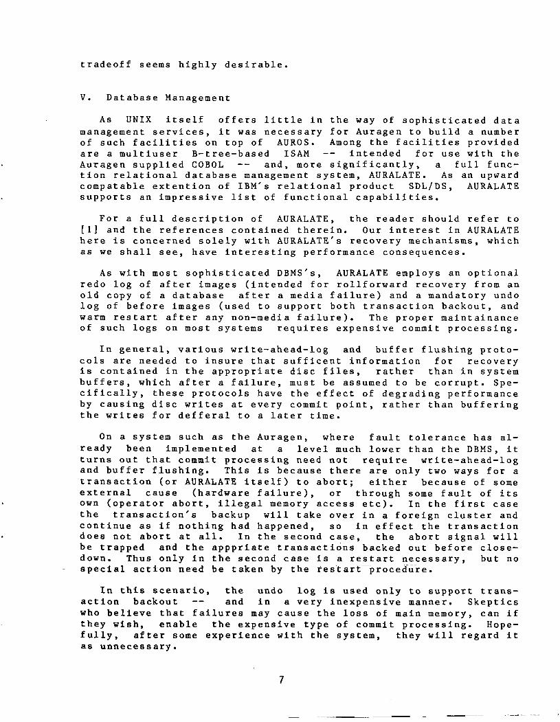
As with most sophisticated DBMS’s, AURALATE employs an optionalredo log of after images (intended for roliforward recovery from an
old copy of a database after a media failure) and a mandatory undo
log of before images (used to support both transaction backout, and
warm restart after any non—media failure). The proper maintainance
of such logs on most systems requires expensive commit processing.
In general, various write—ahead—log and buffer flushing proto
cols are needed to insure that sufficent information for recoveryis contained in the appropriate disc files, rather than in system
buffers, which after a failure, must be assumed to be corrupt. Spe
cifically, these protocols have the effect of degrading performanceby causing disc writes at every commit point, rather than bufferingthe writes for defferal to a later time.
On a system such as the Auragen, where fault tolerance has al
ready been implemented at a level much lower than the DBMS, it
turns out that commit processing need not require write—ahead—logand buffer flushing. This is because there are only two ways for a
transaction (or AURALATE itself) to abort; either because of some
external cause (hardware failure), or through some fault of its
own (operator abort, illegal memory access etc). In the first case
the transaction’s backup will take over in a foreign cluster and
continue as if nothing had happened, so in effect the transaction
does not abort at all. In the second case, the abort signal will
be trapped and the apppriate transactions backed Out before close—
down. Thus only in the second case is a restart necessary, but no
special action ne~ed be taken by th~ restart~proced~re.
In this scenario, the undo log is used only to support trans
action backout —— and in a very inexpensive manner. Skepticswho believe that failures may cause the loss of main memory, can if
they wish, enable the expensive type of commit processing. Hopefully, after some experience with the system, they will regard it
as unnecessary.
7
Another unnecessary luxury is the redo log, if the mirrored disc
option is used. Since the redo log requires additional disc writes,whereas writes to a mirrored disc are essentially free, once againwe see that a low level implementation of fault—tolerance can provide some performance benefits at higher levels.
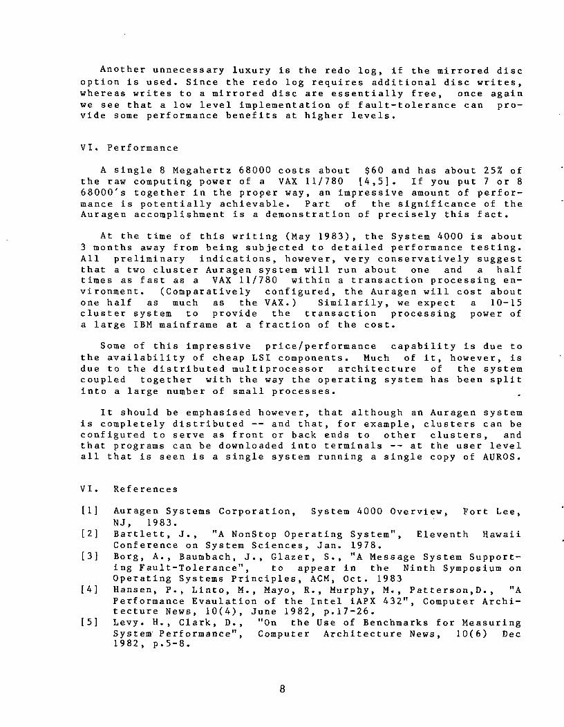
VI. Performance
A single 8 Megahertz 68000 costs about $60 and has about 25% of
the raw computing power of a VAX 11/780 4,5]. If you put 7 or 8
68000’s together in the proper way, an impressive amount of performance is potentially achievable. Part of the significance of the
Auragen accomplishment is a demonstration of precisely this fact.
At the time of this writing (May 1983), the System 4000 is about
3 months away from being subjected to detailed performance testing.All preliminary indications, however, very conservatively suggestthat a two cluster Auragen system will run about one and a half
times as fast as a VAX 11/780 within a transaction processing en
vironment. (Comparatively configured, the Auragen will cost about
one half as much as the VAX.) Similarily, we expect a 10—15
cluster system to provide the transaction processing power of
a large IBM mainframe at a fraction of the cost.
Some of this impressive price/performance capability is due to
the availability of cheap LSI components. Much of it, however, is
due to the distributed multiprocessor architecture of the system
coupled together with the way the operating system has been splitinto a large number of small processes.
It should be emphasised however, that although an Auragen system
is completely distributed —— and that, for example, clusters can be
configured to serve as front or back ends to other clusters, and
that programs can be downloaded into terminals —— at the user level
all that is seen is a single system running a single copy of AUROS.
VI. References
1] Auragen Systems Corporation, System 4000 Overview, Fort Lee,
NJ, 1983.
2] Bartlett, J., “A NonStop Operating System”, Eleventh Hawaii
Conference on System Sciences, Jan. 1978.
3] Borg, A., Baumbach, J., Glazer, S., “A Message System Supporting Fault—Tolerance”, to appear in the Ninth Symposium on
Operating Systems Principles, ACM, Oct. 1983
4] Hansen, P., Linto, M., Mayo, R., Murphy, M., Patterson,D., “A
Performance Evaulation of the Intel iAPX 432”, Computer Archi
tecture News, 10(4), June 1982, p.17—26.5] Levy. H., Clark, D., “On the Use of Benchmarks for Measuring
System Performance”, Computer Architecture News, 10(6) Dec
1982, p.5—8.
8

Transaction Processing in the PERPOS Operating System
J.C. West, M.A. Isman, S.G. Hannaford
Computer Consoles, Inc., Rochester, N.Y.
1.0 INTRODUCTION
PERPOS is an operating system developed by Computer Consoles, Inc.
(CCI) for a new family of general-purpose computer systems based
upon the Perpetual Processing architecture. These are expandable,fault-tolerant systems designed for on-line transaction
processing. The basic architecture has been in use since 1976 in
special purpose telephone industry applications. These new
systems combine many of the architecture concepts from those
previous systems with a set of new general purpose features. Theyfeature, in addition to fault-tolerance, UNIXTM_compatibletransaction processing supported by a shared global file system.
This architecture consists of three basic types of componentshaving distinct functional roles as application processors,coordination processors, and front-end processors* which are
interconnected through a local network. A system may be
configured with a variable number of components operating as
distributed front-end processors and a pool of applicationprocessors that dynamically share the work load and provide faulttolerance.
The multiple components of these systems are logically coupled bya specialized communications interface to operate as a singlefunctional entity, yet each is a separate, independently runningcomputer.
This paper focuses on the system features which provide the
multi-processor, fault-tolerant, transaction processingenvironment. The system is not limited to these features; it can
support many other application models including typical dialogue-oriented interactive sessions and loosely coupled distributed
processing. Different combinations of the same system featuresdetermine these other models; they are, therefore, indirectlydescribed, but not otherwise elaborated upon.
* These names for the system components are used to clarifyissues central to this paper. They are not intended to supplantthe names used in other literature from CCI concerning the
Perpetual Processing system.
9

2.0 SYSTEM ARCHITECTURE
The system architecture consists of a high-bandwidth local network
(Data Highway) which interconnects ~ pool of applicationprocessors, distributed front-end processors, and redundant
coordination processors, as shown in Figure 1. Each application
processor is directly connected to each of the mass storage units.
This arrangement allows the application processors to be
functionally interchangeable and independent of each other and to
run in parallel, sharing the single global file system. Exceptfor this multi-ported disk interface, no unique hardware
requirements are dictated by the architecture.
The application processors (AP) normally execute the main body of
the user’s application. The front-end processors (FEP) provide a
variety of functions, including terminal device handling,transaction generation, and foreign network interfaces. The
interprocessor coordination controller (ICC) serves as a central
coordination and synchronization point for the system.
FIgUre 1
SYSTEM ARCHITECTURE
10

2.1 Multi-Ported Disk Subsystem
The disk subsystem is conceptually the center of the architecture.
The primary function of the other components when running a
typical transaction application is moving data between disks and
terminals, doing a surprisingly small amount of processing in
between.
Perhaps the most unique attribute of the mass storage subsystem is
the handling of replicated disk areas. To gain flexibility and
save disk space, the redundancy of stored data is handled on a
partition basis, rather than on a volume basis. The number of
copies and their physical placement may be determined by the level
of performance and fault tolerance required by each application.Read accesses are optimized by using the first available copywhile data consistency is guaranteed by handling write accesses as
write-to-all copies.
The use of more than two replications of a data area is primarilya performance feature for data inquiry oriented applications.Sufficient data replications can allow each application processor
independent and simultaneous access.
2.2 Application Processors
Application processors are autonomous, each functioningindependently of (but in cooperation with) the other systemcomponents. Even though these processors operate independently,they function as parallel processors running the same application.Load balancing is provided by a feature of the protocol used as
part of the transaction interface between the front-end processorsand the application processors. The front-end processorsdistribute transactions to the application processors based on
application configuration and flow control information.
2.3 Coordination Processors
The system includes two coordination processors. At any giventime one is the active coordination processor and the other is a
warm standby. This standby is the only system component not
actively sharing in the application tasks.
The active coordination processor is the central point for
synchronizing global operations in the system. Global operationsare typically resource request~ Wh~ichcánnot be arbitrated within
a local component, or system status changes which must be
coordinated between multiple components. The largest percentageof these operations are data base locks used to synchronizeconcurrent access of a file by two or more application processors.
11

2.4 Front-end Processors
The system architecture permits a variety of front-end processors.
Ranging in functionality from simple terminal concentrators to
distributed application processors, they differ from applicationprocessors primarily in that FEPs have no direct access to the
global data base, whereas APs have no direct access to terminals.
In other words, front-end processors are functionally
distinguished from the application processors in that they
generally perform tasks which are not penalized by being separatedfrom the global file service.
In a typical transaction application, front-end processors supportsuch functions as screen formatting, sending transaction messages
to the application processors, receiving the replies, and
assisting in recovery process from some system faults. This
separation of “front~end” and “back—end” processing (the back end
is the pool of application processors) improves system modularity,reliability, and dynamic load balancing.
2.5 Data Highway
The application, coordination, and front-end processors are
interconnected by a duplex communications network. These dual
cables are in simultaneous use to enhance both the performance and
the reliability of the system. Based on a distributed packetswitching scheme using a CSMA/CD protocol adapted from Ethernet
1], the network implementation, which uses off-the-shelf
technology, is well suited to the architecture because of its
distributed control properties and high bandwidth.
2.6 Comparison with other Architectures
The Perpetual Processing architecture is a hybrid of centralized
server and distributed processing approaches. It provides direct
access to the file system with a central point of concurrencycontrol and recovery as in a centralized server environment. On
the other hand, it has the modularity and flexibility of a
distributed architecture; in addition, it provides reliabilityfeatures typically lacking in either centralized or distributed
systems.
This architecture also differs from most other fault-tolerant
systems. General-purpose fault-tolerant systems often consist of
a series of interconnected pairs of computer components where the
primary is used for application tasks and the backup comes into
use only if the primary fails. In such systems, operations run
redundantly on the backup or alternatively the primary may
“checkpoint” information needed to assume control to the backupafter each non-retryable step in the transaction execution 2].
12

The checkpointing approach allows the backup to do other tasks,but generates a high level of communication overhead. The
redundant execution approach requires specially designed non
productive hardware.
These other. fault-tolerant systems generally utilize fullydistributed architectures since they already rely on distributed
processing concepts to implement primary and backup computers.This architecture leads to performance limitations, especially for
large data base oriented applications.
The PERPOS approach to processor fault handling is to use standard
transaction recovery techniques 3] 4] to backout partiallycomplete transactions (when needed) and to restart them on another
processor. Recovery is simplified by the central data base and
central lock server architecture (see the section on concurrency
control and recovery) and automated by the front-end processors.
This design causes minimal system complexity and overhead while
providing fault-tolerant execution.
3.0 TRANSACTION PROCESSING FEATURES
Traditional definitions of transaction management include
scheduling, resource management, concurrency control, and error
recovery functions 4]. The last two are associated with
maintaining data consistency and usually are closely related to
the data base management features of the system. These will be
treated separately below.
3.1 Process Control
Transaction management has often been implemented in the form of
entirely new facilities built on top of a general-purposeoperating system, duplicating the operating system functions of
process control and recovery management. We have combined process
management and transaction management to avoid this duplicationand provide some generalized new features of distributed process
control that effectively exploit the system architecture.
The PERPOS transaction execution environment consists of a network
of sender and server processes distributed across the front-end
and application processors. This approach is conceptually similar
to a number of distributed data base proposals 4] 5] 6] 7].The transaction senders are typically responsible for the~- human -
~ifltêfface functions and the servers for data base update or
inquiry functions. In PERPOS these processes are not constrained
from utilizing any of the other features available on the system.They become senders and/or servers primarily by how they are
invoked and the communication scheme that ties them together, not
by following special programming rules.
13

Transaction server processes are allocated by a transaction
initializer (daemon) in each application processor. They may be
allocated when a message is received for that particular server or
may be pre-allocated and execute many transaction instances to
reduce allocation and deallocation overhead.
Transaction program allocation, message distribution, and many
transaction management functions are controlled by a central
transaction description table. This table describes how
applications are to be distributed among the applicationprocessors (they can be unbalanced if desired), how messages are
to be parsed and distributed to each program, and how the
processes are to be allocated (pre-allocation, concurrency level,
recovery class, etc.). An administrative utility allows on-line
modification of this table.
The program interface to transmit or receive a transaction message
consists of standard ‘read’ and ‘write’ system calls. Librarysub-routines permit both sender and server programs to structure
transaction messages to include text and data areas, screen format
descriptions, field attributes, and other application-specificinformation. Filters are also available to strip all but the text
from a message, so that UNIX commands which expect a stream of
characters may be used directly as transaction server programs.
This interface design allows standard UNIX language compilers,
program development tools, debuggers, and even off-the-shelf
programs to be used for application development, yet provides the
special process control, performance and recovery attributes
needed for on-line application processing.
The key feature developed for this sender/server separation is the
communications scheme which connects the two components. This
scheme is also fundamental to achieving the load balancing and
fault tolerance objectives. It reliably delivers messages from
any terminal in the network to one of the appropriate server
processes on any of the application processors. This many-to-many
terminal-to-process interface for transactions is distinctlydifferent from the one-to-one interface of a UNIX ~!login~! session
(which is also supported). The layered protocol which
accomplishes this communications scheme automatically compensatesfor newly added components, components lost due to a fault, or
changes in work load on the running components.
3.1 Concurrency Control and Recovery
In addition to the process control functions described above,transaction management is typically responsible for concurrency
control and error recovery. These are closely integrated with the
data base management facility to provide deadlock resolution and
to prevent system crashes or aborted transactions from violatingdata base consistency.
14

We agree with Stonebraker 81 that the most desirable approach to
achieve internal parallelism of data base access and yet avoid
duplication of operating system facilities for scheduling and
multi-tasking is to use a process-per-user instead of the sIngle-run-time-server DBMS model. For the DBMS to be distributed into
user processes requires improved management of the operatingsystem buffer pooi, an efficient central lock table, and efficient
task switching. Actually, providing these facilities in PERPOS
was the only practical solution to supporting a general DBMS since
the single-server DBMS approach has inherent conflicts with the
multiple application processor architecture.
The notion of “atomic” transactions 4] 6] has so far been the
key to ensuring the consistency of a database in the face of
concurrent operations. A transaction is a series of data base
actions (e.g., read or write a record) which corresponds to a
single change in the real world. The “atomic” property of
transactions is provided by keeping track of all data base changesand undoing or redoing changes after a fault so that the effect of
the transaction is all-or-nothing. Accomplishing this all-or-
nothing execution requires atomicity at both logical and physicallevels. The physical level consists of managing writes to all
copies of a replicated data area and updating the file system’sinternal data structures to maintain consistency; the PERPOS
kernel handles these tasks transparently to the application.Logical level atornicity ensures that multiple physical requests(e.g. ‘read’ and ‘write’ system calls) are treated as a singleatomic operation; it is provided by the DBMS, file-access method
libraries, or directly by application programs.
Implementing atomicity at the logical level is much easier in this
system architecture than in other distributed processing systems.Neither the data base nor the locks are distributed, which means
most complex deadlock and “commit” protocol issues can be avoided.
The single global data base allows most applications to use
single-process transactions. A single process need not use two-
phase commit protocols or other schemes to get all processingsites to agree unanimously on committing the transaction.
Moreover, a centralized lock scheme using the coordination
processor prevents “global deadlocks,” where transactions in
different nodes are waiting on each other to free separate local
locks.
Perpetual Processing applications can, therefore, use single-machine concurrency control and recovery schemes. Also, since the
front-end and coordinat-ion processors ~are not affected by an
application processor failure, they are available to facilitate
simplified, automated recovery. In effect, an applicationprocessor failure is handled in the same manner as a transaction
abort. The data base locks remain set in the coordination
processor (one of the requirements for atomicity) so that the data
are unchanged by other transactions. When the front-end processor
15

is informed by the network control logic that an applicationprocessor has failed (or that a transaction has aborted), it
initiates the recovery procedure.
This recovery procedure differs for different types of
transactions. Transactions fall into three general classes:
repeatable, automatically recoverable, and manually recoverable.
In strict atomicity theory a transaction is “repeatable” if it
will reproduce the original output if rerun 4]. A transaction
which does not update any stored data is repeatable without
recovery. A transaction is “recoverable” if it holds exclusive
use locks on any data it changes and share locks on any data it
reads until the commit point. In plactice, transactions can be
made recoverable or repeatable using many techniques.
Recovery is automatically provided for transactions that use the
system DBMS or file-access methods. The front-end processor is
responsible for initiating recovery transactions, when necessary,
and for resending lost transactions after a transaction abort or
application processor fault. These recovered or resubmitted
transactions will naturally migrate to other applicationprocessors due to the communication interface design.
Strictly following these atomicity rules is not always necessary.
Transactions which are not atomic can also be very useful for
certain applications. For example, in an application where
transaction sequence is not important, the use of share locks on
read data could be dropped. Concurrency can be increased and
locking overhead reduced by not holding read locks until the
commit point or by not using read locks at all. In some
applications (e.g., word processing) the data is less sensitive,and small inconsistencies can be corrected manually. In this
case, delaying the updates until a commit point is reached is not
necessary. This approach is usually used only on a copy of the
data, so the original is still available as a failback. Note that
regardless of the degree of logical level atomicity used, physicallevel atomicity is always mandatory because inconsistencies in the
file system structure would generally cause a system outage.
3.3 Performance Features
PERPOS supports a number of features geared toward allowingcritical applications to obtain their needed system resources.
Basic time-sharing “fair” scheduling algorithms may not be
sufficient for some transaction processing applications. In order
to allow a wide range of transaction processes with different
response requirements to execute concurrently, memory-residencyoptions and extended user-process priorities are provided. Keyprocesses can be locked in memory and run before any time-sharing
type process if the system administrator desires.
16

Data base access performance can be optimized using contiguous
pre-allocated files and features which control kernel buffer poolmanagement. Execution speed can be further increased by using an
initial stack-size designation to prevent run-time stack growthhandling. With proper use of these and other features, highpriority transactions can avoid most common causes of operatingsystem overhead and contention with lower priority tasks.
4.0 USER VIEW
PERPOS provides a UNIX-compatible user interface and program
execution environment. The popular UNIX operating system is
widely known and needs no further description here 9]. It is a
flexible, adaptable system. Achieving UNIX compatibility within
our distributed architecture did present some interestingchallenges. The key design tasks were in providing user
transparency for transaction management, data replication,multiple concurrent application processors, and distributed front-
end processors.
The user view of the system is a single machine environment. That
the system consists of a network of many application processors
and front-end processors instead of a single machine is made
transparent by the transaction and virtual terminal interfaces.
Transaction sender and server programs communicate through a
facility much like a UNIX pipe, while a login session interface
reads and writes a stream of characters just as in a single
processor UNIX.
Data replication is another feature made transparent to user
programs. Reference to a logical disk partition through the file
system automatically will allow a read-from-any- or a write-to-
all-physical-copies. Transparent device access logic uses
standard file system path names for peripherals, just like a
single machine. Moreover, peripherals on any front-end or
application processor are accessed with the same path name from
any component. In addition to simplifying the user view, this
virtual device interface provides system reconfigurationflexibility and makes process migration much easier as a componentfailure recovery technique.
Of course the actual system architecture is not hidden from systemadministration programs. An interactive extent (i.e., disk
partition) maintenance utility is provided to print or modifylogical/physical extent control information (extent name,
location, onhine/offline/error state, etc). Another utility maybe used to introduce new extents or bring them up-to-date and
online. Similar interactive utilities are available for network
maintenance (examining and modifying component state information)and transaction processing application maintenance (transactiondescription table modification).
17

5.0 CONCLUSION
The development of PERPOS started in June 1980 and has included
from 6 to 15 implementers. The PERPOS system has been running in
the development lab on PDP 11/44 application processors since mid-
1982. It was then ported to Motorola 68000-based processors and
has been operational as a full system since December 1982. Future
plans include incorporating many additional hardware developments,including higher performance processors, additional networkinginterfaces, and collapsing the same system functionality into
fewer components.
This system is unique in that it has fault-tolerant features that
do not rely on special hardware and which actually improve, rather
than distract from, system performance for certain applications.The architecture provides productive redundancy where every
processor is handling an active processor load (no checkpointingor process pairs) and the read-from-any logic makes use of all
copies of a replicated database.
Perhaps the most outstanding feature is the user transparency of
many aspects of the architecture and operation. To users this
system appears the same as a typical single process UNIX computer.The Perpetual Processing features are hidden under standard
program interfaces and administrative utilities. Even new
features, like transaction processing, have very few semantical
differences from a standard UNIX environment.
References
1] Metcalf R.M., and Boggs D.R., “Ethernet: Distributed Packet
Switching for Local Computer Networks,” CACM (July, 1976)
pp. 395 - 404.
2] Bartlett, J.N., “A Nonstop Kernel,” CACM (December,1981) pp.
22 — 29.
3] Verhofstad, J.S.M., “Recovery Techniques for Database
Systems,” ACM Computing Surveys (June 1978) pp. 167 - 195.
4] Gray J., “Notes on Data Base Operating Systems,” ReportRJ2188 IBM Research Laboratory, San Jose, CA (October 1978).
5] Hwang C.F., Lin C.S., Parsayl K., Licktenberger W., and
Laliotis T., “A Database Server Architecture for Local
Networks,” IEEE Cat. No. 82CH1739-2 (February 1982), pp.
28-31.
6J Sturgis H., Mitchell J., and Israel J., “Issues in the Designand Use of Distributed File System,” Xerox Corporation, Palo
Alto Research Center, pp. 55 - 69.
18

7] Wilkinson W.K., “Database Concurrency Control and Recovery in
Local Broadcast Networks,” Computer Science Technical Report*448, University of Wisconsin (September 1981).
8] Stonebraker M., “Operating System Support for DataBase
Management,” CACM (July 1981) pp. 412 - 418.
9] D.M. Ritchie and K.L. Thompson, “The UNIX Time SharingSystem,” CACM (July 1974) pp. 365 - 375.
19

A FAULT-TOLERANT TRANSACTION PROCESSING ENVIRONMENT
Peter S. Kastner
Stratus Computer, Inc.
The Stratus/32 multiprocessor, fault—tolerant system for commercial
applications supports on—line transaction processing, batch process
ing, word processing and interactive program development. It uses a
combination or hardware and software that provides continuous pro
cessing ot user programs during computer failure without check
point/restart programming at the user or system level. Central to
the system’s fail—safe operation are processing modules, each o~
which has redundant logic and communication paths, logic and CPU
boards and main and disk memory. Twin components operate in parallel with each other; when one fails, its partner carries on.
Architectural Overview
The Stratus/32 processing modules are connected via the StrataLINK
high—speed coaxial link. Each processing module consists of memory,two Motorola Corp. 68000 CPUs, at least one disk and various peripheral controllers and devices (Fig. 1)
.Both 68000 CPUs are visible
to the operating system, and each executes its own instruction
stream using a shared memory.
Fig. 1. A Stratusl32 system consists of as many as 32 processing modules connected by a high-speed coaxial link. The modules can be
located anywhere within an office building or can be adjacent to each other.
20

Each processing module can be configured as fully redundant, par
tially redundant or non—redundant. The degree of a module’s redun
dancy determines the module’s resistance to hardware failure. A
fully redundant module can withstand failure of essentially any com
ponent in the module without performance or data loss and without
user program interruption. Multiple modules are used only to
achieve greater system capacity; they never serve as backup for
other modules.
Stratus’s distributed virtual operating system (VOS) runs in each of
the processing modules. All modules are equal and can operate inde
pendently, but through the use of transparent local networking soft
ware, VOS makes the entire set of processing modules appear as a
single computer system to programs, programmers and applicationusers.
Although each peripheral device is attached to a processing module,VOS makes all devices available to programs running in any module.
Similarly, a program running in a module creates processes to run in
the same module or in others. An interactive terminal user can cre
ate processes to execute commands or to run programs in any module.
The users need not be aware of the module they are using. Likewise,batch jobs can run anywhere in the system.
All VOS service requests have a uniform interface that is inde
pendent of the processing module on which the work will be performed. For example, a request to open a tile has the same form and
arguments regardless of where the file resides. VOS examines the
file name, looks in a device table to determine the module that owns
the device and performs the requested operation or makes a network
request over the StrataLINK to the VOS running the owning module.
The requesting program does not see the network request. Conse
quently, user programs are unaware of the location of files or de
vices and see the multiple—module network as a single virtual—com
puter system (Fig. 2).
Fig. 2. The Stratus/32 virtual operating system (VOS) makes all processing modules appear as part of a single virtual system in which a/l
devices. files and system resources are accessible as if it were a single computer.
21

Examining the Hardware
A processing module includes one or more cabinets that contain a
complete computer with a logic—board chassis, dual power supplies,peripheral devices and terminal port. A single cabinet holds a
fully redundant module consisting of two 143M—byte disk drives, a
magnetic tape, l6M bytes of memory, redundant CPU boards and a set
of redundant peripheral controllers (Fig. 3).
Fig. 3. A Stratus/32 processing module can contain 16M bytes of
memory, a full set of redundant controllers, two 1 43M-byte disks, a
tape drive and two software-visible CPUs. (Additional disks and
tapes are held in adjacent cabinets.)
A high—speed bus with a 125—nsec. cycle time is central to
processing—module organization. The bus —— virtually two Duses op
erating in parallel —— has two sets of data and control—logic paths.Each .Logic Doard that can be attached to the bus can detect its own
failure and shut itself down. It can also run with a redundant
board that continues to operate in the event of its partner’s fail
ure. Neither logic board is primary, and neither is aware of the
other. The pair of boards appears collectively to other system com
ponents as a rail—safe entity.
Redundant
Redundant
disks
I.
22

The self—checking technique used by each type of board differsslightly, but generally involves the uses of two sets of logic on aboard. Each set performs every operation in parallel with theother. When data are to be sent to the bus or to a device, the results produced by the two sets of logic are compared. If identical,the result is sent onto the bus or to the device. Dissimilar re—suits indicate a board failure, and no data are sent. In this case,a red LED on the board is lit, and an interrupt signal is sent onthe bus. Until the board is tested and logically reconnected bymaintenance software, it remains off—line. The board’s redundantpartner continues to operate, and no other component of the systemis aware of the failure (Fig. 4).
Fig. 4. Self-checking disk controller. Two sets of logic operate in
parallel with each other. If their results differ, a warning light goes on,
and no data are sent until the situation is corrected.
23

The CPU board contains two complete sets of logic and is self—check
ing. Four Motorola 68000 processors provide each board with two
processors visible, to the operating system (Fig. 5).
A redundant
partner CPU board ensures continuous processing in the event ot a
failure ot a CPU board. At a component price of approximately $100
for each 68000, this is a cost—effective solution to continuous pro
cessing that was not practical until the availability ot VLSI tech
nology.
Fig. 5. A single Stratus/32 CPU board contains four Motorola
68000 processors that provide two software-visible processors. The
board is fully self-checking and contains redundant virtual/physical
address-translation maps.
Redundancy is achieved by using a pair of logic boards of each logical entity in the system. Each board is attached to both halves of
the bus, and both boards operate in parallel, performing identical
operations. The output of both boards is placed on the bus at the
same instant and is guaranteed to be identical.
Memory is auplicated in a redundant system so that N megabytes of
program—visible memory is implemented using 2N megabytes of physicalmemory with N megabytes attached to each of two memory controllers.
When data are written to a given memory location, both memory con
trollers respond and write the data into their memory. When data
are read from memory, both controllers respond and read from their
memory.
The controllers and the memory are synchronized and appear to the
rest o~ the system as a single logical entity. Memory subsystemsare not paired with CPUS, bus halves or other system components.
Memory is implemented from 64K RAMs and is packaged on 2M—byteboards. It has a 375—nsec. read—cycle time and is four—way inter
leaved.
The memory system can be dynamically reconfigured to be redundant or
non—redundant. This allows a module to use all available memorywhen full redundancy is not needed. Reconfiguration can occur on
line without affecting running programs.
24

Disks cannot run completely synchronized with each other; they re
quire help from the operating system to provide continuous pro
cessing. Each aisk can be configured to have a duplicate. The mir
ror disk is attached to a separate controller to protect from con
troller failure. When a program writes a record to a redundant
disk, the operating system writes records to the disk and to its
mirror. When a program reads from the disk, the operating systemreads from the disk that is not busy or whose heads are best positioned to read the record. If a read error occurs, the record is
read tram the other disk.
StrataLINKS, like disks, cannot run synchronized. However, the op
erating system has sufficient software error detection to run dual
StrataLINKS as separate parallel links until one fails. Failure at
a link is detected, and data are retransmitted aver the other link
without affecting users of the link.
A failure_sc~narjo
When a logic board or an attached peripheral device fails, it putsitself otf—line, lights a red light on the board and transmits an
interrupt to the operating system. Maintenance software in the system tests the failed board to determine if the failure was transient
or hard. In either case, the failure is noted in a hardware—failure
log file, and selected terminals are notified of the failure. If
the board passes the maintenance—software check, it is resynchro—nizea with its redundant partner and put back on—line, and its red
light is turned off. If the board fails the software check, it re
mains otf—line, and a red light on the system control panel is lit.
A maintenance software process automatically calls the Stratus na
tional service center and passes a data packet containing site and
failure information when hard failures occur. Stratus service peo—
pie Know within a minute of customer failures.
A failed oaard can be replaced in a running system by a nontech
nical person without special tools and without affecting any userts
program. VOS dynamically reconfigures itself when a board is added
or removed trom the system.
Transaction Processing
The Stratus/32 transaction processing encompasses several products.Included are:
VOS File SystemStrataNET
Transaction Processing FacilityForms Management Facility
The Virtual Operating System (VOS) File System manages all the in
put, storage, and output of users’ data. Its flexible file organizations make access easy and efficient from any processing module
in any system within a geographically distributed Stratus network.
25

Data are accessed without regard to physical location or storage de
vice. Files are organized in a directory structure by disk within
processing module. Data objects can be located from anywhere in a
network ot systems by explicitly using the module/directorypathname, or by using a user—defined link to the explicit pathname.There are also a number of features which locate objects implicitly.VOS manages the global file system and controls the allocation,
placement, and recovery of disk space. The input and output mecha
nisms are designed to provide maximum efficiency for interactive
transaction applications.
Data security is very important in a distributed application and
Stratus provides data security as an integral part of VOS. Each
file has an access control list consisting of pairs of user IDs and
associated access rights (execute, read or read/write). Access
rights can be specified by user or group of users and are enforced
by the VOS File System. Access—control lists provide file securitywithout embedding passwords into programs. The lists operate on the
basis of people or groups who access the file; consequently, theyare easy to administer and use. Security is provided regardless of
what program or system commands are used to access files.
~tr ataNE..T
StrataNET, the Stratus networking software, permits two or more
Stratus nodes to run as if they were a single system. Just as users
ot individual processing modules of a system have access to their
entire system, users of a networked system have access to the entire
network without any network—oriented requests or commands. Normal
file operations and inter—process communication operatetransparently to the user’s program. File and directory access con
trol apply to requests across the network. StrataNET has its own
security options that allow the system administrator to permit, permit after network password check, or deny incoming requests on each
system node.
Transaction Processing Facility
The Stratus Transaction Processing Facility (TPF) simplifies application development and provides fast response in a high volume on
line transaction processing environment. Development is simplifiedbecause TPF provides all the system tools and structures required to
develop transaction processing applications. The application pro
grammer is tree to concentrate on application programs. Applicationprograms can be writen in cOBOL, PL/l, BASIC, FORTRAN, or Pascal.
All language features can be used, including I/O statements. Fast
response is achieved with multi—tasking, multiple transaction
servers, and the use of a large program address space.
TPF orfers functions specialized to meet the demands or on—line
transaction processing. It coordinates the receipt and delivery of
messages for an application communicating with hundreds or termi—
26

nals, and initiates a user processing routine upon receipt of a mes
sage trom a terminal or device. TPF monitors the progress of each
user routine, and provides for the parallel execution of multipletransactions.
Terminal handling requester processes and application server
processes can reside anywhere within a system or anywhere within a
network of systems. An application developed to run on a singleprocessing module can easily be run on several modules with no
change to the programs. (Figure 6).
TPF provides for the orderlygrowth of applications —— without the need to reprogram or even to
recompile —— by flexibility in the use of message queues. There are
message queues for communication between a server and the
requesters. A single queue can connect any number of servers with
any number ot requesters. Queues can be redirected dynamically bychanging the pathname of the queue to point to another module on the
same or different system.
ii’F 0t4 F-~kLT~E’LE bL~L~4~
TPF provides complete file protection for transactions, includingtransactions that involve updating data on multiple computer systemswithin a network. This protection ensures data integrity regardlessof extended power failures, communication line failures, systemsoftware failures, application program errors, and operator errors.
The file protection features of TPF simplify the server program de
sign D~ providing the functions that maintain data consistency and
integrity during transaction processing. START, COMMIT and ABORT
transaction commands ensure data consistency and integrity. START
marks the beginning of a transaction, and COMI,UT marks the end.
When COMMIT is issued, the file updates are guaranteed to be com
pleted by VOS regardless of failures due to any cause. The ABORT
transaction results in all files being restored to their pre—STARTstate. Since data can reside on a single processing module or can
be distributed over many processing modules and systems, these com
mands provide data integrity independent of its physical location.
TPF and VOS ensure that the data remain consistent in the unlikelyevent of a tailüre.
if-p
Figure
27
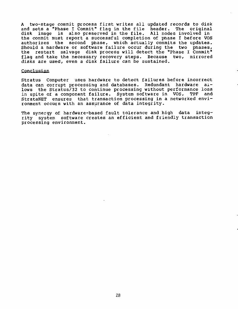
A two—stage commit process first writes all updated records to disk
and sets a “Phase I Commit” flag in the file header. The originaldisk image is also preserved in the file. All nodes involved in
the commit must report a successful completion of phase I before VOS
authorizes the second phase, which actually commits the updates.Should a hardware or software failure occur during the two phases,the restart salvage disk process will detect the “Phase I Commit”
flag and take the necessary recovery steps. Because two, mirrored
disks are used, even a disk failure can be sustained.
Conci usi~i
Stratus Computer uses hardware to detect failures before incorrect
data can corrupt processing and databases. Redundant hardware aj.—
lows the Stratus/32 to continue processing without performance loss
in spite of a component failure. System software in VOS, TPF and
StrataNET ensures that transaction processing in a networked envi
ronment occurs with an assurance of data integrity.
The synergy of hardware—based fault tolerance and high data integ
rity system software creates an efficient and friendly transaction
processing environment.
28

THE SYNAPSE APPROACH TO HIGH SYSTEM AND DATABASE AVAILABILITY
Stephen E. Jones
Synapse Computer Corporation801 Buckeye Court
Milpitas, CA. 95035
INTRODUCTION
The Synapse N+1 (TN) is a computer system oriented to online transaction
processing which emphasizes database integrity and functionality, system
availability, and modular growth across a wide performance range. This paper
gives a brief overview of the hardware and software, then highlights the
approach to achieving high availability. This approach involves five key
concepts:
* Redundant Hardware Components — There is a least one more of each
component than is required for satisfactory operation, hence the name
N+1. These components are not ‘extra’, but in full use at all times.
* Automatic Failure Detection and Reconfiguration — The hardware and
software can detect a failed component, reconfigure the systemwithout It, and continue without operator intervention.
* Fail—safe Database Storage — The DBMS assures that the database will
always be consistent following a failure and that committed data will
not be lost.
* Application State In Database — This fail—safe storage is used by the
system Itself to maintain the state of the online application
systems.
* Online Database Maintenance — The application does not need to be
taken of fline in order to do database backup or reorganization.
THE HARDWARE
The hardware architecture is designed to optimize performance,expandability, availability and concurrency.
Mu]~tiple Ha~dwa~e Components-
Basic to the N+1 approach is that there is at least one more of each
hardware component than Is necessary for acceptable system operation. The
system has multiple processors, buses, memory boards, power supplies, disk
controllers, disks, etc. so that no single hardware failure will render the
system Inoperative. Secondary storage may be mirrored on a logical volume
basis, which may be all or part of a physical volume. Disk drives are sealed
Winchester—type units for higher reliability. Systems are configured with
multiple paths to disks or tapes and will automatically use a secondary path
29
in the event of a failure.
Tight.lry Coupled AFehiteet~uIa
The basic architecture is tightly coupled, centered around the Synapse
Expansion Bus (TM). The Expansion Bus is actually two independent buses with
an aggregate data transfer rate of 64 megabytes/second. Up to 28 processors
may be attached to the bus. They may be either General Purpose Processors
(GPP’s) or Input/Output Processors (lOP’s), each of which Is Motorola 68000
based. GPP’s execute user programs and the majority of the Synthesis (TM)
operating software from shared memory. lOP’s each manage up to 16 device
controllers or communications subsystems. Unlike the GPP, the lOP executes
operating system software from its own 128 Kbyte local memory. lOP’s have DMA
capability to shared main memory.
One problem that multi—processor systems have had In the past Is bus or
memory contention. Synapse has solved this problem with a sophisticated
memory caching scheme. Each GPP has a two set associative cache of 16K bytes.Modifications to the cache are not written through and requests for memory
owned by another cache are satisfied between processors without going to
memory. This mechanism allows a full complement of CPP’s to be added to a
system without degradation.
The tightly coupled architecture provides high performance due to
superior sharing - of resources such as memory and processors. Basic queuingbehavior in the system is single queue, multiple server whereas behavior in
loosely coupled systems is more correctly modeled by serveral single queue,
single server systems. The tightly coupled architecture also provides simplerhardware redundancy. Removing a failed GPP, for example, from the system is
trivial since all CPP’s can uniformly access all memory and 41 peripherals.
Con•figur~able and Rxpandable
Since GPP’s, lOP’s, and memory modules are very independent, systems may
be configured to the optimal mix of processor, I/O, and memory capacity. Each
processor, controller, and megabyte of memory is physically a 15” x 17” board.
There are a total of 64 slots in a single N+1 system cabinet. The system may
be grown simply by adding boards. Additional processors are totallytransparent to user software. They are simply added to the resource pool
managed by the operating system.
THE SOFTWARE
In this section we briefly describe the levels of system software, termed
System Domains, from the hardware out to the user.
System Levels ~Deains~
Monitor— At the lowest level is the Monitor which is stored in ROM. This
code controls hardware self—test and system booting.
Kernel Operating System (KOS) — The KOS is the next layer. Its majorfunctions are memory management, physical I/O, process/processor scheduling,and system reconfiguration.
30

Database (DB) — Directly above the KOS is the Database domain. This software
implements the transaction model, provides fail—safe storage through loggingand recovery code, supports the relational data model, and provides a B*_tree
access method.
Extended Operating System (EOS) — Above the DB code is the Extended Operating
System. This layer uses the DB mechanisms to provide a named object system.This is a hierarchical directory name space for all system objects, e.g~
files, tables, devices, forms, etc. The EOS also provides device independent:1/0.
Transaction Processing (TP) — Above the EOS, is the Transaction Processingdomain. This includes a screen access method and menu system, transaction
thread management, and application restart.
User — Above TP is the user domain. This is where the Command LanguageInterpreter and application programs execute.
The Proease Medal
The process model was designed to optimize the production Transaction
Processing application which is very overhead intensive. Much of its time is
spent satisfying requests for system services, such as I/O or database
accesses. Thus special emphasis was placed during design on minimizing the
overhead required to change context in order to get such a service. The
processor has 16 Mbytes of direct addressability in a segmented addressingscheme. Each of the system domains has a one megabyte segment of
addressability for its. code and another one (or two) for data. Thus
requesting a system service is a jump to a different virtual address within
the same process. The Cross Domain Call and its associated return take a
total of 100 MiCROseconds. This compares with six to ten MILLIseconds for an
interprocess call, a technique used in many minicomputer operating systems.
The Applieatiea Madel
Synapse has integrated software into the basic system which is normallyassociated with add—on transaction processing monitors. The purpose is to
improve the system performance and to simplify the writing of transaction
processing applications. Application systems are built of program units which
are small, separately compiled program modules. Each typically receives a
screen of input, processes it, and displays another screen while terminating.Thus while terminal operators are viewing screens, there is very little
process state and no program state. The TP subsystem provides the mechanisms
to combine multiple Program Units into a single Application Unit and to
provide control of process flow from one Program Unit to the next. The TP
subsystem optionally checkpoints the process state and screen contents between
these units. Thus in the case of a failure, terminals are returned to their
latest screen. In a small percentage of cases, one screen may need to be
reentered.
31

DATARAS~ ORIENTATIQN
The Synapse DBMS plays a central role in the system, including its highavailability requirement. The basic approach is to keep critical information
in database which provides a fail—safe storage. The database functionalitywas a necessary component of the Synapse system for the customer. However,Synapse’s DBMS is unique in that it resides at a very low level within the
operating system and is used extensively by higher levels of system code.
Synapse made it a basic, low—level component for several reasons:
* Performance — DBMS’s often incur a large amount of overhead due to
being built on top of a file system. Synapse has optimized the OS
design for DBMS usage.
* Integrity — The database system provides a fail—safe storage. To do
this with acceptable performance, coordination with low—level
physical I/O is required.
* Simplicity — Higher levels of the operating system use the database
functionality, greatly simplifying their design.
A few points regarding DBMS functionality:
— Relational — It differs from most other currently available
relational systems in its low level, production orientation. The
data manipulation lnterf ace is through language extensions in Pascal
and COBOL. Syntax is similar to file I/O in each system plus a
construct to provide the select operator.
— Assertions — Relational domains are separate system objects which mayhave integrity assertions associated with them. When adding or
modifying tuples, if attributes are drawn from domains havingassertions, they will be checked.
— Transactions — All database activity falls within a per—process
transaction. Commit and Rollback statements in the programminglanguages terminate a transaction and implicitly mark the beginningof the next. Write—ahead log techniques are used to implementtransactions GRAY1]. The log files are mirrored to protect from
disk failures.
— Concurrency — Degree three transaction consistency is the default
GRAY2]. Physical locking with escalation is done on tuple, page or
table granularity. Lock modes are exclusive or shared. Locks are
Implicitly placed when data is touched and freed at end of
transaction. Deadlock detection is done by maintaining wait—for
graphs.
— B*_tree indexes — Indexes are physically separate from data. Index
traversal is highly concurrent and deadlock free. Selection
expressions are evaluated on the data page. Index keys may be
composed of multiple, non—adjoining attributes of different data
types.
32

— Dynamic backup — Relations may be backed up while being modified. At
restore time, changes that were being made during the backup are
rolled out using the same logging u~chanism that implementstransaction rollback.
HANDLING FAULTS
Having briefly described each major component of the system, we can now
walk through the basic approach to handling faults. The following steps
describe the events which occur in a ‘worst case’ failure scenario. This is
one that will cause a complete system restart, as opposed to less critical
failures which may be dealt with without restart.
1. Fault is detected. This may be by parity or other internal hardware
checks, or by an access violation. The memory system provides 2Kbyte
granularity in address mapping with read, modify and execute modes. Access
violations for processes executing in user domain are process fatal. There is
an addressing mode for system domains termed ‘covered’ which is read—only for
system data structures. If an access violation occurs in a system domain
while in this mode, it is process fatal. A process fatal error causes the
process (and its current transaction) to be aborted and restarted. An access
violation occuring in an uncovered system domain is due to hardware
malfunction or software logic error and is system fatal. For system fatal
errors, we proceed to the following steps.
2. KOS marks the failed component. If the fault is due to an internal check,the KOS knows the failed component. This information is recorded in
non—volatile memory for use during restart.
3. Begin reboot. The KOS halts the system to begin a reboot scenario.
Memory is not trusted.
4. Hardware Self—test. The monitor conducts self—test of each unit in
parallel. There is extensive self—test code for verifying each component.
5. KOS initializes.
6. Reconfiguration. The KOS reconfigures the hardware if there is a failed
component. Accesses to I/O devices are rederived around failed components.
Interleaving of memory will be modified if a memory contrpller has failed.
7. DB initializes. At this point the Database recovery system will restore
the database tables to a consistent state. This is done by undoing all
uncommitted transactions and redoing all committed transactions whose
modifications had not made it out to the disk.
8. EOS Initializes.
9. TP initializes. The TP system has maintained state in the database on
each application currently running in the system. This information is
essentially for each terminal: the person operating it, the current screen,
the contents of the variable fields on that screen, and the next program unit
to execute. TP will create a process for each terminal, set its state, and
start it.
33
10. Applications continue. All incomplete transactions have had their
effects removed, so applications simply run again from the input resupplied bythe IT system. For most applications there is no special logic for dealingwith restarts. At this point all processes are continuing normally.
Once the system Is back up, failed boards can be swapped without time pressure
and new boards added without affecting the system.
SUMSMAR’~
The Synapse approach provides protection from a broader class of failures
than most other fault—tolerant approaches. A hardware—based approach attempts
to anticipate all possible types of failures and provide compensating designto provide continuous operation. This is really an unbounded problem. The
approach is effective for many types of failures, but leaves the system just
as vulnerable as conventional systems for failures that fall outside the
failures handled by the design. ~Jithout a transaction—based DBMS, the
database may be quite inconsistent when the system comes up. This could be
disastrous in a transaction processing application and is specificallyaddressed by the N+1 system.
The Synapse approach is based on database transactions and deals with
human, software, and environmental failures in addition to simple componentfailures. The hardware architecture is tightly coupled which yields excellent
performance, configurability and expandability. The transaction processingsoftware provides users simplicity and ease of use in developing online
applications.
Note: Synapse, N+1, Expansion Bus, and Synthesis are trademarks of Synapse
Computer Corporation
REFERENCES
GRAY1} Gray, J., “Notes on Database Operating Systems,” Ope~atIng Systems
Ai~ AdvanGed Cour~se Springer Verlag Lecture Notes in Computer Science, V. 80,T~80.
GRAY2] Gray, J.N., Lone R.A., Putzolu, G.R., and Traiger, I.L., “Granularityof Locks and Degrees of Consistency in a Shared Data Base,” IBM Report RJ 1654
( 24264), 1975.
34

A RICHLY RELIABLE SYSTEM
FOR DISTRIBUTED WORD PROCESSING
Neil B. Cohen, Scott Henderson, Chak Won
Syntrex, Industrial Way West, Eatontown, N.J. 07724
1. INTRODUCTION
Syntrex is an office automation company that has designed highlyreliable computer systems for word processing applications. In this paper we
will describe some of the characteristics of our fully redundant file server,
known as Gemini.
2. SYNTREX SYSTEM OVERVIEW
Syntrex builds an intelligent stand—alone word processing terminal
called Aquarius. The terminal supports standard word—processing functions such
as text editing, printing, a spelling check package, communications software
etc. The terminal connects to several standard typewriters and fits easily on
a secretary’s desk.
Users can connect up to 14 Aquarius terminals in a small cluster systemcalled emini3,5,61. Gemini consists of a central file server which manages a
file system that can be shared by all 14 Aquarii. Gemini is a fully redundant
system. It provides users with an “Always Up”” environment in which to work,in addition to allowing file sharing, and larger storage capacities than one
can get with stand—alone, floppy disk systems.
Gemini systems can be connected via an thernet—like4] interface to
form SYNNET. Users can access documents across the network in a manner that is
totally transparent to the application programs.
The software that runs on a stand—alone word processor is the same
software that runs on Gemini and Synnet, so customers can upgrade their
systems without having to learn new operating techniques.
3. OPERATING SYSTEM
The Syntrex Operating System (SOS) was developed for the Aquarius. SOS
is a sophisticated message switched operating system. We assume that the
reader is familiar with standard operating system concepts such as kernels,
messages, processes, tasks, etc. These will not be defined in the text that
follows. The process and interrupt structure of SOS is similar to that of
hoth21, where system control relies upon teams of processes to perform
specific functions. We have also relied heavily on the concept of a
ink1,3,71, which is used for inter—process communication, and will be
described below.
Many features of the operating system, such as the process scheduler, or
the memory management routines have been implemented in different ways at
different times during the past three years. The inter—process communication
mechanism, which makes this operating system as useful as it is, has undergone
only minor coding improvements during that time.
35

Processes communicate by sending messages to one another. The messages
are routed from process to process by the SOS kernel(s). A message consists of
a message header, followed by an (optional) message body. The header contains
information about the link on which the message was sent, an (optional) replylink (see below), the message type, and the length of the message body.Certain pre—defined message types exist for use with well—known processes
(such as open a file, write a record, create a new process, etc.)
Messages are sent over links. A link is a capability for one—way
communication over a channel between two processes. It is important to note
that a link is unidirectional
When the kernel is told to send a message on a link, it compares its own
machine id with the machine id of the destination process. The Aquariusterminal is given a machine id at the time the operating system is started. If
the destination process is located on the same machine, then the message is
queued directly to the destination. If the machine id is different, then the
kernel places the message on the queue to Gemini. The communication line
protocol will transmit the message to Gemini, where it will be routed to its
destination machine. The kernel in the destination machine then queues the
message to the destination process. It is important to realize that the
communicating processes remain unaware that they are located in different
machines.
When a process creates a new link, it is said to own the link. Ownershipof a link may not be transferred. The owner of a link will receive any message
sent on the link. Until given away, the owner process also holds the link.
The holder of a link can send a message on the link. Subject to having the
appropriate permissions, the holder of a link may give the link away to
another process, thus allowing that process to send a message to the link
owner. The holder of a link cannot determine the identity of the owner. This
helps ensure that there are no hidden dependencies between processes which
would make networking difficult.
The distributed nature of the operating system has allowed applications(such as the editor) to be developed without regard to whether the data files
are located on a local floppy disk, the local gemini unit, or on a remote
gemini located elsewhere. Users have a single, consistent method of accessingfiles which does not change as the customer expands from a stand—alone
terminal to a network of clustered systems.
4. GEMINI
4.1. Overview
Gemini was designed to meet a number of different goals. Primary among
them were automatic information backup and minimal customer down—time, as well
as ease of use for the customer.
Our user community is extremely non—technical. Procedures such as
backing up disks are foreign to normal office operation, and are often avoided
or forgotten by users of automated systems. Gemini’s automatic real—time
36

backup alleviates this problem, protecting users against the loss of
information and at the same time providing a measure of protection againstlost work time due to a down system.
It should be noted that the system is not designed to keep a fullyredundant system operating at all costs, or to connect Gemini units togetherto provide load sharing or further redundancy (a la andem5,7]). Rather, the
system is designed to continue operating without backup in the face of anysingle failure of hardware or software. This allows the customer to continue
to do useful work until such time as a service person can get to the site to
repair and restore the damaged half of the system.
Figure 4.1 shows the hardware used in a Gemini. Each half of the systemcontains a 14 inch Winchester disk drive (this may be expanded to 4 drives per
side), a disk controller (DC), an Aquarius Interface board (Al), a block of
memory that is shared by both the DC and the Al, plus power supplies, batterybackup unit, and phone connection.
The software is designed so that one side of the Gemini is designated“Master”, and the other “Slave”. Messages from an Aquarius are received and
processed simultaneously by the master and the slave. Output from the Gemini
is sent to the Aquarius by the master only. The slave monitors the
communication line while the master is transmitting, and then prepares to
receive the next Aquarius message. At any instant, the slave is prepared to
take over from the master if a failure occurs.
Communications between the Gemini and the Aquarii take place over 14
high—speed, synchronous communications lines. The link level protocol Is a
(slightly) modified version of DLC3,6]. The frame types referred to below
are standard HDLC frame types. For example, RR’s are used to acknowledge the
receipt of IFRAMES (data packets). RNR’s are used to implement flow control
when necessary.
4.2. Master/Slave Relationship
The master/slave relationship is built into the software at the lowest
possible level of the Al. The individual disk controllers do not know if theyare operating as master or slave, or even if they have an active partner at
all. They simply respond to messages asking that disk blocks be read or
written. The operating system in the DC is essentially the same as that of the
individual Aquarius.
The Al is responsible for ensuring that identical messages are beingprocessed on each half of the system. For example, when a message from an
Aquarius is received, the master and slave decode the message, and send the
(HDLC) frame type to their partner. They compare the frame type they actuallyreceived from the communication line with the information from their partner.If the two sides agree, then the frame can be processed. If they don’t agree,the frame must be discarded. For Aquarius to Gemini transmissions, the onlyway the master and slave are likely to disagree is if one side receives the
frame correctly, and the other side has a CRC error. This is a possible, but
rare occurrence.
37

The knowledge of the simplex/duplex master/slave state of the machine
is handled on a strict need—to—know basis. Consider a system running in
simplex (one half active) mode when a message is received from an Aquarius. As
above, the protocol handler decodes the frame type and “sends it to the other
side”. The routine that handles the actual master/slave communications is the
only one that knows that the “other side” is not active. So this routine takes
the information and pretends it has just been received from the “other side.
When the routine returns, the protocol handler discovers that the “other side”
has in fact received the same type of packet, and the frame can be processed.
Transmissions from the Gemini to the Aquarius require that the two
halves synchronize themselves properly. Since the disks operate independently,it is possible that one disk will respond to a request more quickly than the
other (for example, one side may read a block, while the other finds a
marginal disk surface and has to retry several times). When the protocol
handler in the Al prepares to transmit, it must compare the frame type it
wants to send with the frame that its partner has. If the frames are the same,
the master initiates the transmission. As mentioned above, the slave does not
transmit messages; it monitors the master’s transmissions. If the master side
dies, the slave will start transmitting (since it now becomes the de facto
master). When the master and slave disagree on the type of packet to send,
they settle the question by means of a “lowest common denominator” routine.
For example, if the master wants to send an IFR.AME, and the slave wants to
send only an RR, the lowest common denominator is an RR. The master will defer
the transmission of the data frame for a while, allowing the slave Al to get
the data from its disk controller. Eventually, both the master and slave will
have data to transmit, and it will be sent to the Aquarius. Another example
would occur if one side runs out of buffers due to a backlog in the disk, and
the other side does not. The blocked side will try to send RNR (flow—control)
messages, while the other will be sending RR’s or IFRAME’s. The lowest common
denominator in this case is the RNR, resulting in the temporary f low—
controlling of the Aquarius.
4.3. Error handling
Many different types of errors can occur with a system such as Gemini.
Some result from errors in applications programs, some from communications
line failures, hardware failures, and still others from external events (power
failures, people tripping over cables etc.) The system is designed to recover
completely where possible, to continue operatixi~ on one side in the face of a
single, non—recoverable error, and to shut down gracefully when necessary.
The Gemini can do nothing about errors in applications programs.
Rowever, we have found that almost any error that occurs in an application
program running on Gemini can be duplicated on a stand—alone Aquarius. Such
errors do not affect the operating condition of the Gemini.
Standard HDLC recovery procedures are used to re—transmit missed or
garbled link level messages. The system keeps a log of errors (all errors, not
just link level errors) on the disk. If too many recoverable errors occur, the
system will make a “trouble brewing” report to the service center (see the
Service Genie~, below).
38

In the case of a serious failure of either the master or the slave, the
“bad” side is turned off, and the •good” side continues to run. Aquarius
applications are not Interrupted. The customer Is not informed of the failure.
Instead, the Syntrex Service Genie~N places a phone call to the nearest SyntrexService Center, and reports the failure. The service center then will contact
the customer to arrange a convenient time to come out to repair the damagedhalf of the system. During the time between the failure and the repair, the
users have no automatic backup of their work.
The Service Genie is designed so that it will continue to place the
phone call at regular intervals until it gets through to the Service Center.
This avoids the problem of two systems calling simultaneously, and one gettinga busy signal.
The system must protect itself against several different classes of
errors. First, the physical hardware may fail. These errors usually can be
detected by software. They include parity errors, bad disk drives,communication chip failures etc. When this happens, the bad side logs an error
on the good side (a panic message), and shuts itself down. The good side will
continue to run, and will place the Service Genie call. A second class of
failures are catastrophic program failures. This would include such things as
freeing an unallocated message buffer, accessing non—existent memory, etc.
These normally represent “Impossible conditions” and are caught by very
defensive programming. Again, an error message is sent to the good side, and
the system switches over to simplex operation. Service personnel may read the
error logs on both the master and slave in order to determine the cause of a
particular failure.
Some errors will pinpoint the location of the failure almost down to the
chip level, while others can only indicate a general failure of a side or a
board (for example, “DC has gone inactive” gives no indication to the service
person as to ~ the DC shut off, but it does tell him/her which board should
be replaced. The defective board can be returned to the service center for
analysis, while the customer is back up and running in duplex).
A third class of errors are so—called •soft” program errors. These
include communication line errors (bad crc, bad address etc.), expiration of
timers etc. In most cases, the software will recover from these errors.
However, too many errors may indicate marginally functional hardware. If too
many errors occur in a small period of time, the system places a “warning”
phone call to the service center. The system will continue to run in duplexmode, even after the Service Genie call.
For some failures, it is not possible to decide whether the master or
the slave Is the side that is broken. For example, If the two sides agree that
they want to send an IFRAME to an Aquarius, but one side’s message is 50 bytes
long, and the other has a 512 byte message, then obviously the disks have
returned different data. The system can not operate in duplex mode if the
disks are different, so one side has to be turned off, but there is no way of
knowing which message is the correct one. In cases such as this (In itself, an
“impossible situation”) the slave is arbitrarily declared bad, and the master
continues to run. The master will place the Service Genie call. Of course, if
the master is the bad side, it is possible that further failures will occur,
resulting in the complete shutdown of the system.
39

Powerfail is an external event that causes both sides of the system to
shut down. The Gemini is equipped with battery units that allow It to survive
for several minutes after the power fails. During this time, files are closed,
and the system ensures that both disks are properly synchronized. When the
power is restored, the system can be turned on, and it will run properly in
duplex mode. The powerfail is noted in the error log on both sides of the
system.
Finally, there is one potential flaw that must be addressed. At one of
the first customer sites, someone carelessly knocked the phone off the hook;when a failure did occur, the Service Genie could not make its call! The
system ran for several days in simplex mode before anyone noticed that there
was a problem. To rectify this, the system is now designed to place an “I’m
Alive” call from both the master and the slave on a regular (once per week)basis. The service center keeps track of when these calls are expected.Failure to receive a call indicates a problem that must be investigated.
5. SUMMARY
Syntrex has built an easy—to—use, highly reliable office automation
system. The system can be upgraded as needed from a stand—alone system to a
small cluster to a network of clusters with a minimal impact on the customer,
and with the best possible protection for the customers’ information that we
have been able to build.
6. REFERENCES
1] Basset F., Howard J., Montague J., Task Communication in Demos,
Proceedings of the Sixth Sigops, November, 1977, pp. 23—31.
2] Cheriton et. al., Thoth, A Portable Real—Time Operating System, Universityof Waterloo, Department of Computer Science Report CS—li—Il, Oct. 1977.
31 Cohen et. al., Gemini — A Reliable Local Network, Proceedings of 6’th
Berkely Workshop on Distributed Data Management & Computer Networks, February,
1982, pp. 2—22.
4] Digital Equipment Corporation, Intel Corporation, and Xerox Corporation,The Ethernet, A Local Area Network, Version 1.0, September 30, 1980.
5] Highleyman, W., Survivable Systems, Computerworid — In Depth,
Computerworld, 1980.
61 International Standards Organization, High Level Data Link Control
Proposal Doc. No. 1005—ISO TC97/SC6.
71 Solomon 14., Finkel R., The ROSCOE Distributed Operating System,
Proceedings of the Seventh Sigops Principles, December, 1979, pp. 108—114.
40

I~I
( ~8A~~WP &9Ck’~-’P
4—i
41
I,

DATABASE MANAGEMENT STRATEGIES To
SUPPORT NETWORK SERVICES
D. Cohen, J. E. Holcomb, M. B. Sury
Bell Laboratories
Holmdel, New Jersey 07733
1. INTRODUCTION
The Bell System Telecommunications Network is rapidly evolving in
new directions to take full advantage of the emerging Stored Pro—
gram Controlled (sPc) Network technology. The SPC network is
comprised of electronic switching systems, operator systems and
distributed databases interconnected by a data network (Common
Channel Interoffice Signaling, ccis). The SPC Network offers
opportunities to support many new potential customer services such
as expanded 800 1) and Direct Services Dialing Capability (DsDC)
2].
As observed in 2], these services are based on a distributed
architecture with two key network components: the Network Control
Point (NCP) which is a database management system and the Action
Point (ACP), which is a call processing system.
The basic components of a network service are described in the fig
ure below. When a call is made from a local office to a customer
of such a service, the call is routed to an ACP.
TE~MIMALI
42

The special sequence of digits dialed will control routing, and is
actually the address of a unique record maintained within the net
work which contains call processing instructions. The ACP
transmits the dialed address and a request for instructions,
through the CCIS network to the NCP that maintains this customer
record. The NCP returns the related response through the CCIS net
work. The ACP routes the call according to instructions received
from the NCP. Since the service depends on the NCP, NCP reliabilityand recovery strategy are critical aspects of the design.
The following section describes the database administration stra
tegy for the proposed DSDC services. Section 3 describes the
redundancy built in for reliability and survivability. Section 4
shows how DSDC services are supported with the use of Distributed
Database Management concepts such as multicopy updates, concurrency
control, audits and recovery.
2. DATABASE ADMINISTRATION
The database of customer records is maintained by a set of NCPs
that are distributed geographically across the nation to meet per
formance, reliability and survivability needs. According to particular market forecasts, NCP capacity, and performance requirements,several NCPs are required to provide service. To meet the reliabil
ity objectives, redundant hardware and duplex processing are used.
In particular, the NCPs are built using 3B—2OD~ processors 3).Each NCP maintains four on—line copies of the customer record data
base, and the copies are stored on separate disk drives to satisfyreliability and capacity needs.
Survivability considerations result in a mated architecture, where
each NCP is assigned a mate at a different geographic site. Copiesof each customer record at an NC~ are also stored at its mate. One
of the two NCPs that contain copies of a customer record, is designated as the primary for that record. If an NCP fails in spite of
its redundant hardware, its mate will take over responsibility for
handling ACP call processing requests. The geographic distribution
of the •primary and mate NCPs reduces the probability of their
simultaneous failure due to destruction.
Under normal conditions, the entire call processing load associated
with a customer record would be handled by the corresponding
* The 3B-20D is a product of Western Electric Corporation.
43

primary NCP, while the mate would be used only as an on—line
switchable backup.
Besides Call Processing, NCPs would support also customer record
updates. An administrative system called the User Support System(uss) would be employed to create new customer records and to
modify existing ones. Using terminals connected to the USS, custo
mers of DSDC services could build their records in a customized
manner to suit their business needs. The USS would transmit
through an Operations Support Network (OSN), each record to the NCP
designated as the record’s primary.
The primary NCP would be responsible for coordinating the update of
its own copies and those stored at the mate NCP. Updates to the
four local copies of a customer record and those at the mate are
handled by the NCP operating system in a way transparent to the
customer, so that it appears externally as if there was a single
copy at a single NCP site. In the following discussion, the updateof local copies at an NCP site will be considered as a single stepof the update algorithms.
3. REDUNDANCY
3.1 Reliability
The NCP databases form a critical element of the network architec
ture. Failures which disable access to a customer record result in
service interruption to that customer. So, the NCPs have to be
highly reliable and available. To meet these objectives, the NCPs
are built using 3B—20D processors 3]. The processor providesbuilt in error detection, correction, and recovery features to
ensure a smooth system operation.
As the term “duplex” implies, there are two identical processors in
a 3B—20D. Of these, one is “active” and the other is “standby” at
any given time. Each processor has a central control unit which has
direct access to its own main memory, and to the disk system of
both the processors, and indirect access to the other processor’smain memory. During normal operations,the active processor
automatically and continuously updates the standby processor’s main
memory. Thus, if the active processor fails due to either a
hardware or a software error, the standby is ready at all times to
take over as the active unit. And one processor can be tested,serviced or reprogrammed while the other is in operation. The
input/output processor, the disk file controller and the communica
tion links between a primary NCP and its mate are also duplicated.A detailed description of the 3B—20 processor is found in 3].
44

3.2 Survivability
To meet the survivability needs of the service, each customer
record is stored at two geographically separated NCPs. Under nor
mal conditions, the call processing load is split between the two
NCPs by an appropriate distribution of customer records. For a
particular customer, call processing would always be handled by the
corresponding primary NCP. The split can be modified by changingthe primary designation of a subset of customer records from one
NCP to another, using a network management transaction. If an NC?
fails in spite of its redundant hardware, call processing associ
ated with customer records for which it has been designated as pri
mary, is transferred to its mate through the CCIS network. This
operational NC? will process calls related to both the customer
records for which it has been designated as the primary before the
failure, as well as those for which the failed NC? has been the
primary.
4. TRANSACTION PROCESSING
The NCP databases are required to support network services. This
section shows how the database concepts for multicopy updates, con
currency control, audits, and recovery are implemented to supportDSDC services.
4.1 Multicopy Updates
Customers may initiate changes in their service and activate them
directly. Updates could be submitted from multiple sources and con
currently 24 hours per day. The coordinating site concept 4,5,6]was chosen to support these inultisource, multicopy updates. This
requires all changes, independent of their origin, to be forwarded
to the primary NC? associated with the record. The primary NC? acts
as the coordinating site and is thus responsible to propagate the
changes to the copies at the mate. The primary NCP also would
verify the transaction for consistency and for authorization, and
would log the transaction on disk. If the authorized transaction
is valid, the primary NCP would acknowledge the user. This ack
nowledgment would represent a commitment on the part of the systemto complete the transaction even in the case of system failures.
At this point the change would be forwarded to the mate NCP, where
it would be implemented and activated. Activation of an updatemeans that calls would be processed based on the updated version of
the record. The primary NCP would activate the update only after
it received an acknowledgment from the mate on the successful com
pletion of the update. Once the update is activated at the primaryNc~, the system would create an entry in its completed update
45

transaction log.
Under normal conditions, the update algorithm would activate the
change first at the mate NC?, and then at the primary NC? to reduce
the possibility of an “update disappearance.” An update is said to
“disappear” if some calls are processed using a version of the
record which reflects the update while some later calls are pro
cessed using an older version of the record which is not affected
by this update. Such a disappearance effect is seen if the primaryNC? were to activate an update first, process some calls, and sub
sequently fail before the same update was performed at the mate
NC?. In this case, a switch to the mate for call processing would
result in. the update disappearance since the mate NCP would be pro
cessing calls based on the older version.
If communications fail between the primary NCP and the mate NCP,then each NCP would activate the changes without waiting for the
mate’s acknowledgement and would store in a special history queueall the transactions completed since the failure of the communica
tion link. Since neither NC? is down, the CCIS network would con
tinue sending the call processing messages to the appropriate primary NC?. Similarly, the USS would continue sending customer
record updates to the appropriate primary NCP. When communications
between the NCPs are restored, the NCPs would exchange history
queues.
4.2 Concurrency Control
In DSDC services there would be a need to support concurrent mul—
tisource updates of customer records and to assure that updatesoccur without interfering with each other and that they occur in
the order intended by the user 7]. Different users (e.g., custo
mers, operations support personnel, etc.) may concurrently submit
update transactions related to the same customer record. Con
currency control would be implemented by a locking mechanism at the
primary NCP. After an update has been validated and accepted bythe primary NCP, the customer record being updated would be locked
at the primary NCP so that further updates (to that record) are not
processed until the lock is removed. The record would stay locked
at the primary NC? until the update is activated at the primary and
the completed transaction logged. This means that under normal
conditions, the lock stays until both the primary and the mate are
updated. The locking mechanism would enforce the same order of
updates at the primary and the mate NCPs. The locking information
would be kept in a system lock table, so that in the event of a
system failure, this table could be used by the recovery process to
identify abnormally terminated update transactions and to restore
database consistency 8].
46

4.3 Audits and Synchronization
In spite of careful design and testing, database inconsistencies
may occur. Besides various routine audits on the database, demand
audits would be used whenever database inconsistencies are
suspected. Audit failures would be reported to the recovery
mechanism.
A data inconsistency related to a customer record may be between
the on—line copies at the primary site, or between the on—line
copies at the mate site, or between the primary and mate copies.
Synchronization transactions issued by operations personnel throughthe support system, would synchronize the contents of all on—line
copies of the customer record at the two NCP sites. This could be
used to correct update disappearances.
4.4 Recovery Procedures
The main objectives of the recovery process are to restore service
as soon as possible and to minimize permanent loss of data It is
also important to eliminate recovery dependencies between the sites
of the network. With the exception of major catastrophes, a site
should be able to recover by Itself, and restore service.
To meet the above objectives, three levels of failures are identi
fied and separate recovery procedures are designed for each. In a
first level failure, the failed NCP has enough data available on—
site to recover to the pre—failure state. Recovery tools include a
roll—forward process 8) using an off—line backup copy and a com
pleted update transaction log. In this case, the update function
at the failed site would be suspended and would not be transferred
to the mate during the primary’s failure.
In a second level failure, an NCP would not have on—site enoughdata needed for reconstruction. If the off—line copy had been des
troyed, a database copy would be created at the mate site and tran
sported to the failed NCP site. If the transaction log alone had
been destroyed, then the transaction log at the mate site would be
transported to the failed site, where it would be used along with
the (local) off—line backup copy to reconstruct the database. In
this case, the update function would be switched to the mate duringthe primary’s failure.
In a third level failure, all on—line and off—line at both primaryand mate sites would have been destroyed. In this case, the data
base of customer records at the support system would be used for
recovety.
47

If an NC? fails its call processing function would be transferred
to its mate NCP. If the update function is not transferred to the
mate, then the failed NCP can resume call processing soon after
recovery. This is because no changes would have been made duringthe failure to the records for which the failed NCP is the primary.On the other hand, if the update function is transferred to the
mate NC?, then the failed NCP cannot renew call processing immedi
ately •after recovery. This is because the database at the
recovered NCP would not include the effects of the recent updateswhich were received and activated at the mate NC? during the
primary’s failure. A special history queue of updates would be
prepared at the mate site of all transactions completed since the
failure. Once the primary NC? has recovered its database, the primary NC? would first apply the updates from the history queue in
the mate, and then renew service.
5. SUMMARY
The SPC Network employs many current database techniques to providea reliable vehicle for customers in constructing services theydesire. This paper described how high availability and high relia
bility could be supported in the distributed database environment
of the network services by using standard database techniques, such
as multicopy updates, concurrency control, audits, and crash
recovery.
6. ACKNOWLEDGEMENTS
M. Erk, R. M. Ermann, J. W. Nippert and G. A. Raack contributed
significantly in shaping the database architecture proposed for
DSDC Services. We greatfully acknowledge the helpful discussions
provided by C. Lidor, R. C. Kayel, and R. J. Stewart which improvedthe content and readability of this paper.
REFERENCES
1] Wolfe, R. H., “A Distributed Database to support 800 Ser
vice,” Proc of 1CC82 June 13—17, 1982.
2] Roca, R. T., and Sheinbein, D., “DSDC: A New Network Capability,” Proc of 1CC82 June 13—17, 1982.
48

3] Mitze, R. W. et al, “The 3B—20D Processor and DMERT as a Base
for Telecommunications Applications”, Bell System Technical
Journal, Computing Science and Systems,-pp. 171—180, Vol.62,No.1, Part 2, January 1983.
4] Thomas, R. H., “A Solution to the Update Problem for MultipleCopy Databases Which Uses Distributed Control,” BBN ReportNo. 3340 July 1975.
5] Cohen, D., “Implementation of a Distributed Database Management System to Support Logical Subnetworks,” The Bell SystemTechnical Journal Vol.61, No.9, November 1982.
6] Stonebraker, M., “Concurrency Control and Consistency of Mu!—
tiple Copies of Data in Distributed INGRES,” Third BerkeleyWorkshop on Distributed Data Management and Computer Net
works 1978.
7] Bernstein, P. A., et al “Analysis of Serializability in SDD—
1: A System for Distributed Databases,” CCA Report No. CCA—
77—05, 1977.
8] Gray, J. N., “Notes on database operating systems,” IBM
Research Report RJ—2188, February 1978.
49

Experience with a Large Distributed Banking System
J. Robert Good
Bank of America
Systems Research 3438
Box 37000, San Francisco, California 94137
System Overview: The Distributive Computing Facility (DCF), automates the tel
ler function for Demand Deposit Accounts (i.e. checking accounts) and Savings De
posit Accounts at Bank of America. The system, which has been operational for
over five years, provides inquiry and memo posting functions to the ten million
account database. Updates are “memo” in that the system does not replace the flow
of paper instruments (e.g. checks and deposit slips) which is still the basis for
updating the true account ledgers. The ledgers are maintained by batch accountingsystems using tape-resident account masterfiles. Every morning condensed files
produced by these batch systems are loaded onto the DCF system replacing the files
from the previous day.
There are about 1100 branches of Bank of America in California, each with an aver
age of one Programmable Control Unit (PCU), one administrative terminal and eightteller terminals. The branches are supported by leased lines which hub into one
of two data centers in Los Angeles and San Francisco. The overall network scope
is: 10,000 terminals, 1,120 Programmable Control Units (PCU), and 115 communi
cation lines (2400 BPS FDXSDLC) with PCUs multidropped up to 14 per line.
Each data center houses a DCF cluster which provides the transaction services
against half of the statewide account data base and supports half the terminal
network. Each DCF cluster is comprised of eight DCF Modules connected by a local
network. The Module itself is a local computer network comprised of four GA
16/440 minicomputers and is the basic unit of transaction processing in the sys
tem. The DCF clusters are linked with a pair of 9600 RDLC lines to allow any
terminal to gain access to any account. Both clusters have the same hardware con
figuration including 40 disk spindles where the database resides.
The typical input message is about 20 characters and the response 120. The trans
action processing profile is simple and not resource intensive. The mix between
inquiry and update transactions is: 60-70% inquiry (3 disk reads), and 30-40% updates (3 reads, 1 replace).
The statewide transaction load is divided approximately 55% in Los Angeles and 45%
in San Francisco. The Los Angeles volumes are: 390,000 transactions per average
day, over 500,000 transactions per peak day, 84,000 transactions per peak hour,and 30 transactions per peak second
DCF Module: Two of the four processors are communications frontends called Mes
sage Handling Processors (MliPs) and the other two are database backends called
File Management Transaction Processors (FMTPs). Figure 1 shows the module configuration. The four processors communicate over a 1.2 megabits per second communi
cations bus called the intra-module link. The protocol is SDLC multi-pointcontention and there is no master station.
Each module also contains a line printer, a TTY, four tape drives and eight disk
spindles of 64 megabytes each. The printer, owned by one of the MHPs, is used as a
hardcopy log of all status messages originated by any of the processors. The TTY
50

is used as an emergency system console and for maintenance. It is switchable to
any of the four processors. Each NHP owns two tape drives for message logging.These tape drives are switched to the F1’ITPs for data base load and unload. Thedisks contain a portion of the data base, the program libraries for MHPs and
FNTPs, and control files. Notice that the MHPs have no disk, so they are IPL’dfrom an FIITP through the intra-module links.
The module is configured such that the aver
age load can be handled by half the hard
ware. Every component has a backup normallysharing the load equally. Backup components
automatically assume full processing load
when a failure occurs.
During normal operation, one MHP/FNTP pairworks on half the module’s lines and data
base, the other pair working on the other
half. There is a watchdog timer on each
processor. If the processor does not reset
the timer periodically, the timer turns the
processor off and notifies the peer (MHP or
FNTP). If the failed processor is an MHP,the peer NH? assumes responsibility for the
module’s full complement of lines. If the
failed processor is an FMTP, the peer as
sumes control of the full module database.
The T~iHPs recognize an FMTP failure when mes
sage communications are unsuccessful. Aftera preset interval, the MHPs will assume the inaccessible FHTP is down and beginsending all messages addressed to this module’s FMTPs to the single survivor.When a processor is re-IPL’d, it automatically recovers its regular share of
equipment and transaction load.
Any work in progress on a failed processor is lost. This simple recovery philosophy is acceptable because a transaction updates at most a single file record.There is no automated message recovery. The terminal users provide the messagerecovery by submitting a query for an account in the case no response is received,and resubmitting the account update if necessary.
DCF as a Network of Modules: The previous discussion described the hardware and
general function of a module. The data and external lines are partitioned over as
many modules as necessary to control the network and meet the transaction processing requirements of peak message traffic. t~Iodules are connected with a redundant
pair of communication buses identical to the intra-module network described above.
However, the inter-module network is distinct from each module’s four node in
tra-module network in that only MHPs are connected.
The determinant of the number of modules is the processing rate of the FMTP and thenumber of applications. A NH? can handle approximately 50 messages per second and
up to 16 lines in normal mode, or 32 during peer failure operation. An FNTP can
only handle about four messages per second. Currently the account database andthe external lines are partitioned across five modules in each cluster. There isalso one module for a DCF cluster management application and two spare modules for
expansion in each cluster.
51

Programs operating in the IBM batch environment use a control file to produce dai
ly database load tapes for each FMTP after the batch ledger posting systems com
plete. Also on the tapes are routing tables and line/station tables for the
related MHPs. These become part of the MHP resident software after the next IPL
and inform each MHP as to the PCU configuration and database distribution. The
latter table maps a particular branch number to the FMTP which has the database
for that branch. Mapping is clearly necessary to properly route messages.
DCF Cluster Management: A DCF cluster presents a single system image to the operations staff without introducing a single point of failure. This capability was
implemented because 32 or more independently operated computers could present a
difficult operational problem. A special application called the Network Operations Center (NOC) was developed as well as unique hardware to provide remote
processor IPL and status display.
The NOC is a set of software developed to provide computer operator console func
tions. There is a dedicated DCF module where the full set of input and outputfunctions reside. Each processor in the cluster (MHPs and FMTPs) has a set of exe
cution routines that execute commands entered at the NOC. Commands are entered on
terminals connected to the NOC FMTP’s for execution on any processor. The com
mands are interpreted by the NOC FMTPs and put into a standard internal form. Theyare sent through the NOC module’s intra-module link to the NOC MHP for routing to
the target processor, command responses are routed back to the NOC FMTP and dis
played on the originating terminal. In situations where a processor generates a
message to the operator, it is logged on the respective modulets printer and a
copy is forwarded to the NOC module for action/information. The switchable TTY
configured in each module serves as an operator console when the NOC is down byswitching it to an MHP. A subset of NOC command input and output formatting rou
tines is present in each MHP.
Remote IPL and status display capability was developed for all processors to allow
processor IPLs from a single remote panel. Each processor also has software con
trolled display lights on this panel to indicate normal mode, hard stop, and in
tervention required conditions. Unique IPL RON controllers were fabricated for
each FMTP and MHP which provide: normal IPL, backup version IPL, and full memory
dump. These functions can be activated either from the remote panel or local to
the respective processor. In the case of the MHP, the full memory dump goes to
tape, with FMTP to disk. There are several additional options for normal and
backup IPL on the FMTP. There is normal IPL from program libraries which takes
about three minutes. A normal and backup IPL from a memory image is also providedwhich takes 10 seconds. The library load is only used when new software is intro
duced.
External Network Management: The external network covers the state of Califor
nia and involves the facilities of over 50 independent phone companies. It was
clear that to provide the required availability extensive diagnostic equipment was
necessary to pinpoint problems. This led to the development of the Network Con
trol Center (BANC). Sophisticated telecommunications diagnostic equipment allowsnetwork technicians to diagnose problems in the external network. Racal-Milgo T-7
optioned modems provide a side band diagnostic channel which is automatically used
by a DEC PDP 11/45 to monitor the line and modem condition. The PDP 11 providescommands that can be transmitted on this side band to exercise or change the sta
tus of remote modems.
With respect to the control of the 1100 PCUs, it was decided not to put secondarystorage on the PCUs and instead to provide the ability to load them through the
52

network from a central database of PCtJ programs. This was done due to the cost of
the floppy disk drives (1100 is a large multiplier) and by the need to control the
version of the software that was in each PCU. A special application was developedfor every module with external lines. This application resides in the FMTPs and
can load any number of PCtJs concurrently. The line loading caused by the amount of
data transmitted, however, necessitates a limit during peak transaction loads. A
PCtJ can be booted by an IPL button on the unit or invoked by an operator command.
Typical Message Flow: Figure 2, shows Northern California Branch 200 and illus
trates message flow. The Branch contains a PCU which is one of the drops on a line
connected to MHP AM1 in the San Francisco data center. The following examples as
sume a teller in that branch is negotiating a check drawn a Bank of America branch.
AM1 is continually polling the PCU
in branch 200. ~ihen the teller en
ters the transaction and presses the
send key, the PCU responds positive
ly to the next poll and sends in the
message.
The message has been mapped by the
PCU onto a standard DCF message for
mat and the target application has
been identified. AM1 stamps the
message with its ID, the line ID,and the PCU ID for use later in
routing the response. AM1 selects
the appropriate application routing
algorithm. For Demand Depost Application (DDA) messages, the account
number being debited is separatedinto its component parts: branch
number and account number within
branch. The routing table mentioned above is indexed to identify the location of
the necessary branch data. Two cases will be discussed:
Case 1: This occurs if the check is drawn on Branch 200, and the data for branch
200 is on San Francisco Module A as shown. AM1 does input routing, determines that
the data is on AF2 and sends the message to AF2 on the intra-module link. AF2
queues the message and when next-on-queue, the DDA software is brought into memo
ry, memo reduction in balance for the account is effected, and the response to the
teller is sent back to AM1 on the intra-module link.
Case 2: This occurs if the account being debited is domiciled in branch 800. The
data for this branch is on HF2 in Los Angeles. The input message routing algorithmof AM1 yields the Los Angeles center ID. AIll’s inter-center routing table yieldsthe inter-module link address of BM1 which has one of the inter-center links to
Los Angeles. This is a two entry table, containing BM1 and Hill. After each in
ter-center routing action ocurs in Au, the entries are flipf lopped to attempt to
evenly load both paths to Los Angeles. BM1 is then sent the message over the in
ter-module link. Bill goes through the same input routing process as Au, and fur
ther discovers that it has the link to the Los Angeles center, so the message is
sent over the inter-center link.
53

BN1 in Los Angeles then performs the same input routing as the previous two t.IHP’s.
HF2 is identified as the target FMTP, and it receives and processes the message as
described above.
When HF2 has processed the message, the response is returned to HM2 through the
intra-module link. HM2 does response routing based on the originating MHP ID
(SF-AM1), discovers it belongs to San Francisco and accesses the inter-center
routing table to make the appropriate routing decision to transmit the response
back to AM1.
In any of the above flows, a single processor or link failure will not affect the
sucessful transmission of the message unless a processor fails while that message
is in transit and before being sucessfully transmitted to the next point. The
paths chosen for transmission clearly would be different if one of the links or
processors mentioned above were down. If both paths to a target are down, an error
message is returned to the teller. If both paths are down preventing a response
from being returned to its origination point, the message is discarded after beinglogged to the NOC. If an intercenter link is down, the MHP with the down line will
forward a message to the other gateway MHP. If both lines are down, the second
gateway to get the message will recognize this situation and dispose of the mes
sage as described above based upon whether it is an input or response message.
Software: The operating software was specially constructed by Bank Staff in a
joint development with the vendor. The FMTP has extensive software error handlinglogic. This was developed because application software and disk-related system
support functions reside there. All of these were identified as much more likelyto change than the MHP software. The FMTP handles two types of errors: Recovera
ble and Non-recoverable.
Recoverable errors are those that can be associated with a particular message.
These types of errors are defined to be those occuring when the software is not op
erating in interrupt handling state. Examples are stack overflow or underf low,
protection violation, or invalid request for supervisor services. The occurance
of this type of error causes diagnostic information to be captured and the message
to be discarded.
A Non-recoverable error is defined to be one which occurs during interrupt handl
ing or a recursive error condition generated by the inability to recover from a
suspected recoverable error. When such an error occurs, a memory dump is taken
and the processor halted. This causes an automatic switchover of disks to the
surviving FNTP and a switchover notification message to be sent to the NOC.
FMTP switchover processing occurs when a processor fails and the peer must assume
responsibility for all the disks. This involves handling the interrupt from the
System Safe Controller of the failed FMTP, initializing the disk controllers that
are now to be managed by the survivor, reading in the file control blocks and highlevel indices, and preparing for application access of these files.
Switchback processing occurs after a failed FMTP has IPL’d and is requesting re
sponsibility for its normal complement of disks prior to resumption of transaction
processing. After the restarting FMTP has IPL’d itself by accessing the disks
through the dual ported controller, it sends a message to the survivor requestingresponsibility for its disks. The restarting FMTP then opens its complement of
files and begins normal transaction processing. MHPs detect that the restartingFMTP is available for processing when it begins to respond to its ~tItm alive” mes
sages which all processors exchange on a regular basis.
54

Operat~ona~ Experience: The system is very successful from a performance, avail
ability, and operability standpoint. Using representative data from the peak hour
in Los Angeles (10:00 a.m.): 87% of transactions receive a response within 3 sec
onds (as measured at the PCU), 99% of transactions receive a response within 6
seconds, FMTP database load takes less than one hour.
Because of the distributed nature of this system, the scheme for calculating the
availability statistics warrants some explanation. The duration of unavailabili
ty of any component is recorded by the operations staff. The unavailability of a
duplicated component does not affect the user, so does not affect the computed
availability numbers. When both prime and backup components are unavailable, the
user is affected. The availability statistics reflect the severity of the outage
as well as the duration. For instance, the DDA data is distributed over 40 disk
spindles in each center. The data is not duplicated. If a spindle is unavailable
for 40 minutes, 1/40th of the database is down. Central site unavailabity for
that outage is one minute. If a DDA module is unavailable for 40 minutes (bothMHPs or both FMTPs), 1/5th of the database is unavailable. The central site una
vailability for that incident is eight minutes. The monthly figures are then
figured by taking these weighted unavailability statistics and dividing by the
committed minutes of operation for the month to yield the monthly statistic.
End user unavailability is the central site unavailability plus the network una
vailability. Network unavailability is average PCU unavailability due to PCU
problems plus average PCU unavailability due to line problems. Using Los Angelesstatistics for the first seven months of 1982, DCF delivered 99.96% central site
availability and 99.64% end user availability. The causes of the end-user per
ceived unavailability are: 50% due to line problems, 39% due to PCU problems, and
11% due to central site problems
During the first seven months of 1982, the Los Angeles data center averaged 63
line problems per month. These took an average of 287 minutes to resolve. There
were 54 PCU failures per month averaging 260 minutes of outages. 266 teller and
139 administrative terminals failed on average per month. These numbers representthe number of times vendors were called to resolve problems. The trouble calls
from users to the network technicians average well over 2000 per month. The net
work technicians are able to resolve about 50% of trouble calls themselves. Theyare able to do this in large part because of the Network Control Center (BANC).
The contribution of central site unavailability to overall unavailability is quitelow (11%). The month of June in 1982 was analyzed in detail because it appearedfairly representative. The following central site failures were recorded: 23
failures, 128 minutes of component unavailability, 6 minutes average to fix with
only five failures visible to users because of redundancy and automatic backupThis resulted in 30 minutes of module unavailability for the month which was re
corded as 6 minutes of central site unavailability (30 minutes I 5 modules in the
cluster).
Conclusions: The system is highly available and central site unavailability con
tributes very little to the overall system unavailability. If any improvementswere to be made, attention to the communication line unavailability would have the
best potential for improvement. Several design features of DCF have clearly had
a beneficial impact on availability:
1. Redundancy Redundant components with automatic switchover reduces the visi
bility of failures to end users.
55

2. Granularity Spreading the load over multiple modules also reduces the im
pact of a total module failure.
3. Rapid IPL The ability to IPL the FMTPs in 10 seconds creates situations in
which an IPL is the first thing done when strange things happen, not the last.
The above features must be set in the context of a system having no message integ
rity. Processor failures cause message loss. The system does not have a 24 hour
operating requirement, allowing hardware maintenance, software maintenance, and
testing to occur at off-hours.
A significant factor contributing to centralsite availability is the stability of
the software, with less than three changes being made per month. These are mostlyMHP table changes reflecting a change in terminal, line, or PCU configuration.
Very few software caused outages are visible to users. This is somewhat deceptivehowever. During the initial conversion of the system, the availability was con
sistently over 99% even when the software was very failure prone. This was a
result of the granularity, rapid IPL capability plus the fact that most errors
were FMTP application software failures of the recoverable variety where processor
shutdown did not occur.
The overall conclusion to be drawn is that a network of minicomputers have been
effectively used to support a large terminal based application in place of a more
traditional mainframe approach. The Distributive Computing Facility is settingthe standard within Bank of America for the operability and availability of online
systems.
56

Distributed Database Support
I. Aaro, J.G. Holland *)
Philips Data SystemsJarfglla, Sweden
Apeldoorn, Netherlands
1. Introduction
In a traditional real—time system all data reside in a central database
and transactions operating on the database are handled completelywithin one central computer. By a transaction we mean a sequence of
operations which transfer the database from one consistent state to
another one. This sequence is atomic, that is, itis executed
completely or not at all.
More formally expressed a transaction defines both a success—unit (itis executed completely or not at all) and an integrity unit (the data
it uses is not accessible by other transactions). It is the
responsibility of the programmer to define where in a program a
transaction starts and ends. The transaction handling system of the
DBMS will then guarantee that the transaction is executed properly.
In a distributed system data reside in many computers and the execution
of a transaction in such a system usually means that data in many
different computers have to be accessed. That is, the transaction
processing Is distributed and it is the responsibility of the network
data manager to guarantee that a transaction is executed completely or
not at all. This can be a tricky problem in the general case. However
we have found that by splitting a transaction into a main transaction
and one or more secondary transactions which cooperate according to
certain rules, the transaction control can be simplified. It becomes
especially simple if all real time updating of the database is replacedby so called delayed updating. Delayed updating means that the database
is updated after that the system has signalled to the user that the
transaction has been completed. The network datamanager in the nodes
involved will guarantee that the requested updates really are done. The
delay before the database is updated can vary from just some
milliseconds to batch update during the night (applicationdefined).
*) Acknowledgements
We. want to thank our colleagues, S. Arnborg, T. Beerda, Tsj.Beetstra, H. Ljungkvist, P. Oman, B. Sanden, J.J. Schenk and
L. Zwanenburg in Apeldoorn and Jarfglla for their valuable
contributions in the discussions on distributed processing.
57

2. Architecture-
In our model a distributed database system consists of a set of nodes
which are interconnected via public and/or via local networks. The
relevant nodes in such a system can be classified as:
— terminal node
handles one or more workstations and executes dialogue—oriented
parts of transactions. This node type has no local database.
— database node
contains a local database and all software needed to handle it.
Data in such a database can be accessed from other nodes. No
workstations are directly connected to a database node.
— complete node
include both terminal node and database node capabilities.
Networking nodes, e.g. gateways, are notregarded in this paper. We
assume that high level transmission services up to the transport level
of the OSI reference model are available at each node.
The above node types can be combined to form different types of
distributed database system structures. Moreover, the architecture
permits one computer to hold more than one node. For example, one
computer can hold one or more database nodes where each such node is
an independent unit. Each node has a unique logical name, own data
etc. The node names are globally known and are used to address the
nodes.
From an application programmerTh point of view the distributed
database consists of a set of logical databases. Logical node names
are used as references when an application process in one node wants
to access data in another node. To find the proper node name, the
requesting process can use a locate function. This function will
either consult directories or execute a user defined algorithm to getthe proper node name.
The application programs are structured into Main Transaction Programs(MTP5) and Secondary Transaction Program (STPs) and these cooperate to
execute transactions.
MTPs are front—end programs and the execution of such a program is
initiated by a user. The execution of a MTP takes place in a terminal
node or in a complete node. MTPs handle the man—machine dialog,
processes information and accesses the database, both local and non
local databases can be accessed. A non local access means that a
command message is sent to that node which holds the data requested.An answer message will later return the results.
58
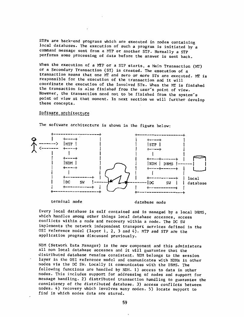
STPs are back—end programs which are executed in nodes containinglocal databases. The execution of such a program is initiated by a
command message sent from a MTP or another STP. Normally a STPperforms some processing of data before the answer is sent back.
When the execution of a NT? or a STP starts, a Main Transaction (NT)or a Secondary Transaction (ST) is created. The execution of a
transaction means that one MT and zero or more STs are executed. MT isresponsible for the execution of the transaction and it willcoordinate the execution of the involved STs. When the NT is finishedthe transaction is also finished from the userTh point of view.
However, the transaction need not to be finished from the systemThpoint of view at that moment. In next section we will further developthese concepts.
Software architecture
The software architecture is shown in the figure below:
-+ ÷
0 I +—---+ I I +----+ I> IMTP I I I ISTP I I
< +----+ I I +----+ I,‘ I I I I I I
_
I +----.+ I I 4—---+- + II INDM I I I INDM I DBMS I II -~-----+ I I -~-------÷- + L_J
I + ~ I I —+ I localI IDC SW IDC SW I database
1 -+ I I ÷ -+
+ -+ —1-
terminal node database node
Every local database is self contained and Is managed by a local DBMS,which handles among other things local database accesses, access
conflicts within a node and recovery within a node. The DC SW
implements the network independent transport services defined in theOSI reference model (layer 1, 2, 3 and 4). MTP and STP are the
application program discussed previously.
NDM (Network Data Manager) is the new component and this administersall non local database accesses and it will guarantee that the
distributed database remains consistent. NDM belongs to the session
layer in the OSI reference model and communicates with NDMs in othernodes via the DC SW. Locally it communicates with the DBMS. The
following functions are handled by NDM. 1) access to data in othernodes. This includes support for addressing of nodes and support for
message handling. 2) distributed transaction handling to guarantee the
consistency of the distributed database. 3) access conflicts betweennodes. 4) recovery which involves many nodes. 5) locate support to
find in which nodes data are stored.
59

3. Distributed transaction handling
The notion transaction is defined in the Introduction. In a non
distributed sytem the end user interaction and the database processingwill in general proceed in parallel. The database reflects the most
current situation, that is, it is in accordance with the most recent
transaction.
In a distributed system the Network Data Manager is responsible for
the execution of the MT and the related STs. MTs and STs can cooperatein many different ways. We have found that a great deal of
applications can be handled with three types of cooperation. For each
cooperation type we have defined a ST type. The ST types are:
sub transaction
A ST of this type is always executed simultaneously with the
invoking MT and forms with respect to transaction commitment and
cancellation one integrated transaction, that is
— database modifications generated by the sub transaction will
only become definitive after commitment by the MT at the end
of the MT.
— a premature cancellation of the MT (by itself or by the
system) also cancels the sub transactions.
So the functions “COMMIT” and “ROLLBACK” having a MT as
subject will extend their scope such that also the sub
transactions executed or under execution in other nodes will
be involved in the functions.
When a sub transaction has finished its task it will get the
status ready—to—commit. A sub transaction in ready—to—commitstate can only be committed or rolled—back by the invoking MT.
This ST type is used for real time updating of a database.
side transaction
A side transaction is — like a sub transaction — a ST which is
executed simultaneously with the invoking MT. The difference is
that when it has finished its task all database modifications it
has generated are definitive. NDM gives no support in the
revocation afterwards by the MT.
Although this fact restricts the usage of a side transaction,there is still an Important area where It can be appliedsuccessfully, namely for for inquiry of a database. An inquirynever needs rollback and therefore can be performed as a side
transaction.
The advantage of a side transaction is that its control requiresless internal transmission of control information and
consequently it has a better throughput and responsiveness.
60

delayed transaction
A ST of this type runs independently of the invoking MT and it is
never executed simultaneously with the MT. Invocation calls for
delayed transactions will namely be effectuated only after the MT
has terminated normally. Cancellation of a MT impliescancellation of the invocation requests for delayed transactions
done by the MT. It is because of this fact that the delayedtransaction will not be able to return output Information to the
MT.
NDM guarantees that invocation calls for delayed transactions are
forwarded to the right destination nodes and that the requested
delayed transactions really are executed completely. The
guarantee Is valid even if there are times problems with the
physical communication lines or if an involved computer crashes.
If for some reason a requested delayed transaction cannot be
started or finished in a proper way a system failure has happenedand NDM will take care of this and send a message about the
incident to an operator at some network control center.
Delayed transactions may themselves also invoke other delayedtransactions e.g. in the node of the originating MT (post
processing).
By considering a transaction as a MT and one or more STs of different
types we assume that application system design can become simpler.
Only in those systems where real time update Is a necessity are STs of
type sub transaction required. We believe that many applicationshandle only transactions which consists of side transactions and
delayed transactions.
Side transactions are used for querying the database and delayedtransactions for updating the database.
The advantages of this approach are:
short response time. The user has not to wait until all updatesreally are done.
— works also in offline situations.
— small overhead In NDM for recovery purposes.
priorities can be assigned to queries and updates. There are also
possibilities to postpone updates during peak hours.
The drawback of this approach are:
— the values in the database are not completely up to date. The
updates are not done immediately.— the distributed database can be inconsistent for some time.
However it will converge to a consistent state gradually.
These drawbacks have little importance in applications where the risk
for access conflicts is small and/or where it does not matter if the
data are absolutely up to date: for example in banking systems It does
not matter If the balance of an account becomes negative, many
reservation systems accept overbooking.
61
4. Restart
To be able to restart after a local database crash, back—up copies of
the local databases have to be taken regularly. A back—up copy at one
node can be taken independently of the other nodes in the network. A
back—up copy can be taken when a local database is In a consistent
state. This happens when all MTs, sub transactions and delayedtransactions in a node are completely finished. By closing a node for
new updating transactions a local database will soon enter a
consistent state. Normally this happens quickly, however if a node
contains sub transactions in a ready—to—commiC State and the
invoking MTs are in other computers and these are down, it can take a
long time before a consistent state is reached.
The restart procedures must cover the following error situations:
— line failure
— local database crash
— error in after—image logTo be able to recover from these error situations NDM must contain
some extra overhead. The amount of overhead needed for delayedtransactions is rather small because delayed transactions have only a
local scope. However the overhead needed to handle recovery of sub
transactions is both complicated and extensive.
Moreover a distributed database system must also be able to restart
after many coincident errors. The normal restart procedures work well
if one or many line errors occur and/or one or many local databases
crashes at the same time. This is also valid for different
combinations of line errors and errors in the after image logs.
However, if a local database and its after—image log are damaged at
the same time a catastrophe has happened, that is, it is not possibleto restart with information available locally. This situation also
arises when a node is totally destroyed because of fire, sabotageetc. To restart from such a situation information stored in other
nodes is needed. Special restart procedures must be used and these
often require manual participation. The restart front a catastrophe is
simplified very much if only delayed transactions are used for
database updates.
5. Conclusions
Dividing a transaction in a Main Transaction (the user oriented
process) and Secondary Transactions (the database processes) will helpto develop secure and ~reliabl~ dlstribut&d systems. In addition the
use of only delayed transactions for updating will make transaction
processing much simpler. In that case local COMMIT and ROLLBACK
happens, and this simplifies restart and recovery. Only the secure
execution of the local delayed transactions must be guaranteed.
In how many applications is real time updating a user requirement?We believe that many applications can be developed with only the use
of STs of type delayed for distributed database updates.
62

Distributed Data Management Issues
in the LOCUS SysLem*
Gerald J. Popek and Greg Thiel
University of California at Los Angeles
1. introduction
The LOCUS project at UCLA has taken the view that issues in distributed computeroperation should be primarily addressed at the operating system level, so that all clients:data bases, transaction processors, language systems, and application software can take
advantage of the solutions. Accordingly, LOCUS, a Unix compatible. distributed operatingsystem operational on an Ethernet of VAX computers at UCLA, provides a very high degree of
network transparency, both for the file system and tasks. A global name facility, supportedby partial replication, is provided. High reliability features such as support for replicatedfiles across the network, nested transactions, and graceful partitioned operation are all
present. ‘A LOCUS bibliography is given at the end of this paper.
However, the best test of a distributed operating system results from its use by applications. For example, one expects the existence of network transparency plus operating system reliability features would make it feasible to obtain considerable distributed data
management functionality merely by running a single machine data base system in a
LOCUS-like environment. (Parallel processing of an individual query would have to be added,of course.) But a test of this stategy is necessary.
In pursuing this approach to distributed data management at UCLA, a number of database issues related to distribution have surfaced. In this note, we wish to comment on threeof them: name spaces, the relationships among transaction mechanisms, and multilevel
logs. We turn to these now.
2. Distributed Name SpacesThe distributed file system component of an operating system must provide a distri
buted name space supported by at least partially replicated catalogs. The name space of a
data base management system is similar to a file system name space. if the underlying dis
tributed operating system (DiOS) provides a global and transparent name space, togetherwith extensive replication and recovery support after partitioned operation, as found in
LOCUS, then substantial advantage may be obtained by an appropriate mapping of the distributed data base management system’s (DDBMS) name space onto the DiOS’s name space.This section indicates how that mapping can be done.
Consider the nature of the DDBMS name space. it should be global and transparent,using partial replication for the supporting catalogs, in order to provide flexibility and ease
of use {PopekB3J. The strongest motivation for replication support for a global name spaceis the flexibility it provides when combined with transparency. When a transparent, globalname space is provided, applications can easily move from being centralized to being distributed, if, in addition, the name space is compatible with a centralized DBMS (CDBMS) then
the applications of the CDBMS can be directly transported to the DDBMS and run withoutmodification.
Two considerations suggest it should also be hierarchical in nature. in a large distributed system, name collisions at the data base level could be frequent (for example, manyerri.ployee data bases). A hierarchical name space would avoid this problem. Further, if the
DDBMS supports partitioned relations*, a hierarchical relationship among them is natural.
‘This research has been supported by Department of Defense contract DSS-MDA-903-82-C-
0189.
Partitioned relations provide, in norm~i operation, the ability to store portions of relations
at diferent sites, and yet have the data base system ma3ce their composition transparent to
the user.
63

One critical aspect of a distributed system’s name space is the affect of a failure on the
support mechanism. A user should see minimum adverse affects after a failure. Consider a
catalog replicated at two sites and the affect of a communication failure between the sites.
Catalog operations on the two catalog copies must be able to continue independently and a
catalog merge algorithm must be able to make the two copies consistent when the failure is
corrected. The partitioned operation concept is this view that functions can continue to be
provided in spite of failures and the underlying system will make things “right” when thefailure is resolved. In LOCUS, partitioned operation and merge is provided as an integralpart of the directory system used to support the name space.
2.1. DDBMS To DiOS Name MapptngThe D1OS’s name mechanisms can provide most of the name support if the DDBMS’s
name space is directly mapped to the DiOS’s name space. For example, the directoryrecovery procedure would perform the merge and conflict detection of the DDBMS’S name
catalog required after network reconnection. In this way the DDBMS does not rebuild muchof the functions of the DiOS. Also, with one common mechanism, functionality and performance improvements are shared by both “users’.
The alternative is for the DDBMS to build its own name space within files of the DiOS. Inthis case, the DDBMS must duplicate many of the functions provided by the DiOS: replicationof the appropriate entries, partition merges of the catalogs, etc. On the other hand, performance tuning is DDBMS specific. The catalog could look much Like a normal relation, for
example. Representation of the hierarchy may be confusing when displayed in this fashion,however.
There are other DDBMS tables, such as protection catalogs, which also share common
characteristics with the naming facility. They benefit in a similar fashion from use of the
underlying system directory management facilities.
2.2. DiOS Requirements
Mapping the DDBMS’s name space onto the DiOS’s name space places several requirements on the DiOS’s name support mechanism..
First the user needs to be able to associate some variable length data with each direc
tory entry in order to store the catalog information. The user must be able to change thedata (update the catalog information) and the system must be able to detect conflictingupdates (that result from partitioned operation, for example). Lastly, the DDBMS must beable to specify a particular entry easily. For this purpose there should be a directory entryidentifier equivalent to a tuple identifier, as if the catalog were a real relation. The DDBMScan then have tuple identifiers for all relation and catalog tuples and. only be concerned at
the access method level about representation.
2.5. A Proposed Mapping
Given the DiOS functions proposed above, the DDBMS name space can be supported inthe following manner.
For each node in the DDBMS hierarchy there will be a directory in the DiOS file system.The children of the node will be entries in the directory. in addition each entry will contain
any additional data describing the child nQde. AlL other- catalogs will -be -maintained irr~a~
~hil~d~iirè~tTóry wiih~uples being directory entries in their directory. The catalog’s inforrnation will be stored in the user supplied data of the directory entries that comprise the cata
log. in order for the recovery mechanism to perform properly the name of a directory entrymust be a unique key for the catalog.
We assurDe the relational model for thscus~ion purposes.
64

A case study is presently being completed to test this view of distributed data management. The single machine Ingres database system is being integrated into the distributedLOCUS environment, using a name map quite similar to what has just been outlinedThiel83J.
3. Transactions in a Distributed Environment
It. is becoming the conventional wisdom that the atomic character of transactions in distributed environments, especially in the face of failures, will be increasingly important.Nested transactions have been suggested as a natural consequence of assembling independently developed software packages, and as a way to limit the efTect of intra-transactionfailure. A commonplace example would be a program X, itself a transaction, that involves anexisttng database function, uses a prepackaged transaction-processor for another service,and performs some of its own updates directly to the underlying file system. Assume thatboth the DB and TI’ are bu.ilt to perform their functions atomically.
3.1. The Problem
Currently available transaction mechanisms are inadequate as tooLs to support such anenvironment. First, it is typical in virtually all available systems today that the transactionfacility is implemented in the application package: the data base system, the transaction-processor, etc. The interfaces to these functions that are made available to clients (peopleorprograms) are simple:
Begin.IransactjonAb orL..transac tion
En&jransactjon
are typical. This approach makes it impossible in general to construct the program X mentioned above and assure its atomicity. The reason is illustrated by the code fragment below.
X BEGIN TRANS DE
BEGIN TRANS TI’
F~E WRITE
END TRANS DB
END TRANS
Failure between the two END TRANS calls means that the DB transaction completed while theTP transaction aborted. (Note that properly nesting the called transactions does not solvethe problem either.)
Further, of course, it is the responbility of X’s recovery software to undo its own. fileupdates. This amounts to building another transaction mechanism. Its decision to completeor abort also cannot be synchronized from the available interfaces.
3.2. Possible SoluUon~
There are several approaches to this problem of assembling nested transactions. First,if an inverse operation exists for each transaction (e.g. DEBIT/CREDIT. CREATE/DELETE), orif an UNDO log is retained, and it is possible to determine which transactions completed andaborted, and recovery mechanisms can be run. immediately upon resumed operation, (sothat the results of apparently completed transactions have not yet been seen), then thecompleted transactions can be undone. In a distributed envrionrnent however, it is difficultin general to fulfIll this last requirement.
65

Second, one could require that the functional interface to each transaction mechanism
be altered to give finer control. At least a PREPARE command must be made available,whose semantics are the familiar internal step of the two phase commit protocol. Then it is
possible to compose transactions by having the parent transaction PREPARE all of the participants before completing any of them. It is still the responsibility of the application program X to implement its own transaction mechanism, to make sure that all participant transactions are PREPARED before ENDing them, and to record sufficient information in its logso that recovery operates correctly.
Lastly, one could provide a full nested transaction in a basic distributed operating system. All application packages would use it in the standard simple way, and the mechanism
is built once. This is the approach taken in the Locus system. While the mechanism is
extensive (approximately 7000 lines of C code for two phase commit, mtra and inter transac
tion synchronization, version stacks and associated control software) the mechanism exe
cutes surprisingly fast, primarily imposing a cost at the end of the parent transaction that is
just a few times greater than that required to close all resources anyway. This approach is
very attractive if one can accept a. homogeneous distributed operating system base. Other
wise, the other options need to be considered.
3.3. Multi-Level LogsTransaction implementations typically involve extensive use of logs and supporting
fadilties. Many applications create objects which are log-like for reasons other than transac
tion support. Therefore, a log type could be considered as a reasonable facility to be provided by the underlying system. When the transaction support is provided by the OS then
the generalized log type provided by the OS would permit all the OS’s applications to use this
object type for any log-like activities. Since a DBMS represents one major class of OS applications it is reasonable to expect that database related applications may well be able to take
advantage of a log object type. Therefore we are ex~rninir1g a multi-level log mechanism.
As an example, consider a three level software system composed of a operating systemkernel, a DBMS and a editor built on top of the DBMS. At the operating system level many
types of asynchronous and synchronous events may be logged: configuration changes,software failures, device errors, two-phase coordinator commit points, etc. At the DBMS
level more data needs to be logged, including software failures, usage data, partitionedoperation information and catalog recovery information. The editor may keep a keystrokefile or information in order to provide the user with an undo function. Such logging facilities
are being investigated as part of the LOCUS based distributed database effort.
4. Conclusion
Repeatedly it appears that one can profitably avoid solving the same problem at multi
ple levels in computing systems. To do so however requires understanding the tasks to be
accomplished at each leveL so that commonality and restructuring can be accomplished.Each of the approaches raised in this note is an attempt to develop this commonality.
5. References
ENGLISH, Robert M. and Gerald J. .Popek,”Dynamic Reconfiguration of a Distributed Operating System, UCLA Technical Report.
FAJSSOL, S., Availability and Reliability 1s~ues in Distributed Databases, Ph.d. Dissertation,
Computer Science Department. Unversity of California, Los Angeles, August 1981.
GOLDGERG, Arthur, Steve Lavenberg, and Gerald J. Popek, “A Validated Distributed SystemPerformance Model”, UCLA Technical Report.
66

GOLDBERG, Arthur and Gerald J. Popek, “Measurements of a Distributed Operating System:LOCUS”, UCLA Technical Report.
LEITh1ER, Gerald and Gerald J. Popek, “An Algebraic Model for the Specification and
Verification of Distributed Systems”, UCLA. Technical Report.
MOORE-CHOW, Johanna D., Erik T. Mueller and Gerald J. Popek, “Nested Transactions and
Locus”, UCLA Technical Report.
MuELLER, Erik T., Johann.a D. Moore and Gerald J. Popek, “A Nested Transaction Mechanismfor LOCUS”, UCLA Technical Report.
PARKER, D. Stott, Gerald J. Popek, Gerard Rudisin, Allen Stoughton, Bruce Walker, EvelynWa.lton. Johanna Moore-Chow, David Edwards, Stephen Kiser, Charles Kline ,“Detection of Mutual Inconsistency in Distributed Systems”, to appear IEEE Transactionson Software Engineering, May 1983.
POPEK, Gerald J., J. Moore-Chow, D. Edwards, C. Kline, G. Rudisin. G. Thiel, B.Walker, “A Net
work Transparent, High Reliability Distributed System”, Proceedings of the Bth
Symposium on Operating Systems Principles.
POPEK, Gerald J. and Bruce Walker, “Transparency and its Limits in Distributed OperatingSystems”, UCLA Technical Report.
FOPEK, Gerald J., Greg Thiel and Charles S. Kline, “Recovery of Replicated Storage in Distributed Systems”, UCLA Technical Report.
TI-flEL, G., Partitioned Operation and Distributed Data Base Management System Catalogs,Ph.d. Dissertation, Computer Science Department, Unversity of California, Los
Angeles, June 1983.
WALKER, Bruce J. and Gerald J. Popek, “The LOCUS Distributed File System” UCLA Technical
Report.
67

Research in Database Programming:
Language Constructs and Execution Models
* * * * 4
J.W. Schmidt M. Reimer P. Putfarken M. Mall 3. Koch M. Jarke
(*) (fl) (.4)
Universität Hamburg ETH ZUrich New York University
Fachbereich Informatik Institut für Informatik GBA - CRIS
SchlOterstr. 70 ETH - Zentrurn 90 Trinity Place
D-2000 Hamburg 13 CH-8092 Zurich New York, N.Y. 10006
Fed. Rep. of Germany Switzerland U S A
I. The Database Programming Languages (DBPL) Project
The DBPL project at the University of Hamburg is centered around the
integration of database models and programming languages. It is
motivated by the insight that most of the interfaces used to access real
databases are not stand-alone data sublanguages but complex programs
requiring the functionality of a high-level programming language and of a
database model, both integrated into a unilingual and homogeneous
framework (SCHM77]. SCHM78L The relational approach to databases and
Pascal-like programming languages, both known for their well-designeddata structuring capabilities, have proven as a framework particularly
suitable for that integration effort.
The usefulness of high level database programming languages has been
demonstrated by several successful applications of the database
programming language Pascal/R (SCHM80I. It is used for teaching database
management courses, for database applications (e.g.. 50 Mbytes in fisheryresearch BIOM81]), for the development of database programming
methodologies tBRODB1), and as a target language for very high level
languages like TAXIS at the University of Toronto. and the natural
language system HAM-ANS at the University of Hamburg.
The DBPL project evolved from ideas resulting from the design and
implementation of Pascal/P from 1975 to 1979. The project has the
objective to investigate in more depth language constructs and execution
models for essential database programming problems. In particular,issues of query evaluation and transaction management as well as their
mutual interaction are addressed. The project takes a high level
approach in the sense that it emphasizes the development 0f high level
language constructs together with their transformation and evaluation
over representational issues. A notion central to our approach is that
of a selector for relation variables providing abstract access to
subrelation variables. The concept of a selected relation variable is
used to essentially support query evaluation as. -well a-s transaction and~
integrity control.
The DBPL pro)ect (principal investigator: Joachim W. Schmidt) -
is supported by the Deutsche Forschungsgemeinschaft (DFG)
under grant no. Schm. 450/2-1.
68
2. The Selector Concept
Since, in practice, several users contribute to the data integratedinto a relation, individual users often do not require access to full
relation variables. In the following, we sketch the notion of a selector
(MALL82] that provides access to selected parts of relation variables.
The uniqueness of key values within a relation provides a basis for
selecting and altering individual relation elements. Let us assume that
the relation, relk, has a key composed of the two attributes ki and k2.
In Pascal/R syntax the statement
IF SOME r IN relk (<r.kl,r.k2) <kvl,kv2))
THEN relk :~ C <.. ,kvl, . .
,kv2, ..)
ELSE relk :~ C. . ,
kvl, . . ,
kv2, . .
> 3;
replaces (:&) the value of the relation element with the specific key
value, <kvl,kv2>, by a record <..,kvl,..kv2, ..). or inserts (:~i a new
element, if an element with this key value does not exist. The above
statement is equivalent to the assignmentrelk :~ C EACH r IN relk: NOT (<r.kl ,r.k2> <kvl ,kv2>)
,kvl.. . ,kv2, ..> 3;
If we switch from the set-like perception of relations taken so far
to an array-like or table-like view, the above statement can be
interpreted as an assignment of the record <..,kvl,..,kv2,..) to the
relation element identified by its key value, (kvl,kv2>. We identify a
relation element by means of a so-called element selector and write,
e.g., relk(kvl,kv2]. Assigning a record variable, rec, to a selected
relation element, relktkvl ,kv23 :~ rec. is defined to be equivalent to
the following conditional assignment:
IF <rec.kl,rec.k2> <kvl,kv2>
THEN relk (EACH r IN relk: NOT(<r.kl,r.k2> <kvl,kv2)), rec]
ELSE (exception);
The notion of an element selector can be generalized to selectors
denoting arbitrary subrelation variables. This is achieved through the
concept of a selector generator that allows for the definition of
selectors based on arbitrary selection predicates. The above element
selector, for example, is equivalent to the definition
SELECTOR sk (kfl:kltype; kf2:k2type) FOR rel: relktype;
BEGIN EACH r IN rel: <r.kl,r.k2) <kfl,kf2> END;
which introduces a selector name, parameters, a formal base relation and
a selection predicate. The notation relk(kvl,kv2] is therefore
equivalent to elksk(kvl,kv2)] selecting the relation relk through the
selector, sk, with the key value, <kvl.kv2>, as actual parameter.
In its most general form, a selector is based on an arbitraryselection predicate p
SELECTOR sp (...) FOR rel: reltype;
BEGIN EACH r IN rel: p(r, . . .) END;
and the assignment relk(spt . . .:~ rex is equivalent to
IF ALL x IN rex (p(x, . .
THEN relk :~ (EACH r IN relk: NOT p(r,. . .
)
EACH x IN rex: TRUE]
ELSE ~exception);
69
A predicative notation for the selection of subrelations is of highvalue for the definition of access rights and integrity constraint3 as
well as for the definition of generalized access paths (permanent
selectors). Sections three and four describe how the strategies for
query evaluation and transaction management applied in the DBPL projecttake advantage of selectors.
3. Query Evaluation
From a database programmers point of view, a query is a
relation-valued expression based on a selection predicate. The predicate
is a well-formed formula of an applied many-sorted predicate calculus
with existential and universal quantifiers where the “sorts” are the
range relations (relation expressions) to which element variables are
bound.
A general evaluation procedure for relational expressions performs
the following steps JARK82a];
(1) It applies logical transformations to the expression that
- standardize the expression (e.g., transform into prenex normal
form) in order to simplify subsequent transformations,
- simplify the query (remove redundancy) to avoid double work, and
- ameliorate the query (e.g., apply the range nesting method as
described below) to streamline the evaluation and to allow
special case procedures to be applied.
(2) It maps the transformed expression into alternative access plans.
(3) It chooses the cheapest access plan and executes it.
This procedure provides the framework for our research activities in
query evaluation JARKB2b].
The recognition and adequate processing of special classes of
expressions plays an important role in our approach to query
optimization. We have identified syntactic properties of a class of
quantified queries, so-called perfect expressions ()ARKB33, lending
itself to particularly efficient evaluation. Perfect expressions include
quantified tree queries and certain classes of cyclic queries. We have
developed range-nesting techniques that, given some perfect expression,
produce an equivalent (range-) nested expression, which subsequently
controls a stepwise execution of the evaluation procedure (inner nestings
first). At each evaluation step a subexpression is evaluated that is at
most as complex as
EACH r IN rel: SOME/ALL x IN rex ( p(r,x) )]
where rex denotes an already evaluated inner expression and where p(r,x)
stands for a conjunction of dyadic terms. Certain combinations of
comparison operators and quantifiers, e.g.,
(EACH r IN rel: ALL x IN rex ( r.A < x.A )]
give rise to further simplification of a single step, e.g..
(EACH r IN rel: r.A < MIN(rex,A)]
ancL~so contribu~te to-a ‘cheap’ evaluation of quantified queries that are
usually perceived as being rather ‘expensive’.
The method can be improved further by explicitly making use of
permanent selectors. Prior to its evaluation, any subexpression can be
checked if it is equivalent to some selector predicate, for which the
corresponding selector is supported by an access path. If so, a
70

subexpression, (EACH r IN rel: p(r. ..)], can be replaced by the
equivalent selected variable, rel(sp].
Advanced access methods are explored with respect to their
usefulness for our approach to query processing. We are especially
interested in multi-dimensional access methods. i.e., access methods that
efficiently support access over attribute combinations. Such access
methods directly implement various classes of conjunctive
intra-relational queries, such as point queries, range queries and
partially specified queries. Thus, they are the prime candidates for the
support of permanent selectors.
Finally, we are working on extending the scope of query optimization
from one expression to a set of expressions. In database programming
languages where concurrent access to databases is supported by language
constructs for the formulation of compound database operations
(transactions), there are two lines of attack. First, we are working on
the simultaneous optimization of all expressions contained in one
transaction (vertical scope extension), and second, we are investigatingthe idea of a shared query optimizer that processes expressions of a set
of active transactions simultaneously (horizontal scope extension). Both
approaches have specific coordination requirements with respect to
concurrency control (e.g., minimizing the chance of transaction backup).
Furthermore, they differ in the set of viable architectural alternatives
for their implementation (e.g., vertical scope extension can be
implemented by linking a completely separate query optimizer to each
transaction, whereas horizontal scope extension always requires some sort
of synchronization). In addition to a substantial improvement of overall
performance we expect to achieve further insight into the complex
interdependencies of query evaluation and transaction management.
~. Transaction Management
In addition to concepts for data selection, a database programming
language has to provide linguistic support for transaction definition. A
transaction is a compound database operation that transforms a database
from one consistent state into another. In EREIMB1) and (MALL82], •the
procedure concept of high level programming languages has been extended
to a transaction concept by adding the semantics that transactions are
executed either entirely or not at all.
A set of transactions can be executed in parallel if no transaction
changes a (selected) relation shared with another transaction. It is the
responsibility of the concurrency control component of a database system
to make sure that a (selected) relation variable with the access right,WRITE, is imported exclusively, i.e., by only one transaction at a time.
Since selected relation variables, as introduced in section two, are
variables in their own right, transactions can import them and can
operate concurrently on non-overlapping partitions of the same relation.
In the DBPL project, we investigate two types of predicative
approaches to concurrency control. The (predicate) locking method avoids
conflicts between parallel transactions a-priori by guaranteeing the
dlsjointness of (selected) relation variables before the database is
accessed. ~irco the disjointness test is purely based on access
71

intentions (predicates) locking of predicates has the disadvantage that,
in general, more conflicts are signaled than may actually occur.
An alternative method analyzes conflicts a-posteriori when the
actual data changed by parallel transactions are known. The test for
disjointness consists of querying these data by the predicates defining
the selected variables that are imported by the transaction to be
analyzed. An execution of a transaction is conflict-free, if and only if
the query against the data changed by the transactions that completed
during its execution produces an empty relation.
Since the performance of pure a-priori approaches as well as of pure
a—posteriori approaches is acceptable only under extreme - pessimistic
resp. optimistic - assumptions about the transaction load, we are
experimenting with combined methods that are adaptable to changing load
profiles. Another motivation for combined methods is the insight that
concurrency control and query optimization require coordination. We are
working on a basically a-posteriori transaction handler that schedules,
however, ‘read-only’ transactions due to a-priori principles. In that
case the query optimizer can simultaneously eva]:uate queries of read-only
transactions without risking that any of these transactions has to be
restarted because of a conflict.
5. Current status of the DBPL Pro~ect
The design of the database programming language DBPL has been
completed using Modula-2 as its algorithmic kernel MALL82], tSCHM83].
Language compiler, query optimizer and concurrency manager are being
implemented on a VAX-li under VMS in Modula-2, which our group moved from
a POP-li to the VAX-il and adapted to the VMS environment K0CH82].
References
810M81] “Post-FIBEX Data Interpretation Workshop~, BIOMASS Report
Series No. 20, SCAR/SCOR/IABO/ACMR, Hamburg, September 21st to
October 9th, 1981.
(8R0082] Brodie, M.L. “On Modelling Behavioural Semantics of
Databases”, Proc. 7th VLOB Conf.,Cannes, 1981.
tJARK833 Jarke, M., Koch, J. “Range Nesting: A Fast Method to
Evaluate Quantified Queries”, Proc. ACM-SIGMOD Conf.,
San Jose,
California, May 1983.
tJARKB2a) Jarke, M.,Koch, 3. “A Survey of Query Optimization in
Centralized Database Systems”, Technical Report CRIS 64 GBA 82-73,
New York University, Nov. 1982.~
(JARK82b] Jarke, H., Schmidt, J.W. ‘Query Processing Strategies in the
Pascal/P Relational Database Management SystemS~, Proc. ACH-SIGMOD
Conf.,Orlando, Florida, June 1982.
72

Lr~OCH82) Koch, J.,Mall, M.
,Putfarkeri, P. “Modula-2 for the VAX:
Description of a System Transfer” (in German~, Proc. of the Meeting of
the German Chapter of the ACM on Pascal-like Programming Languages.
Kid, July 1982.
MALLB2] Mall, M.,Reimer, M.
,Schmidt, LW. ‘Data Selection, Sharing,
and Access Control in a Relational Scenario”, Symposium on Conceptual
Modelling: Perspectives from Artificial Intelligence, Databases and
Programming Languages, Intervale, New Hampshire, June 17-20, 1982,
to be printed in “Perspectives on Conceptual Modelling”
Springer-Verlag, 1983,
(REIM81] Reimer, M.,Schmidt, J,W. “Transaction Procedures with
Relational Parameters”, ETH Zurich, Institut fuer Informatik,
Report 45, October 1981.
(SCHM83] Schmidt, J.W,,Mall, M, “Abstraction Mechanisms for Database
Programming”, Proc. ACM-SIGMOD Conf., San Francisco, June 1983.
(SCHM8O] Schmidt, J,W, und Mall, M. “Pascal/R Report”, Fachbereich
Informatik, Universitaet Hamburg, Bericht Nr.66, January 1980.
(SCHM79] Schmidt, J.W, “Parallel Processing of Relations:
A Single-Assignment Approach”, Proc 5th VLDB Conf,,
Rio de Janeiro,
October 1979.
SCHM7B] Schmidt, J.W. “Type Concepts for Database Definition”,
Shneiderman, B. “Databases: Improving Usability and Responsiveness”,Academic Press, 1978,
(SCHM77) Schmidt, J,W. “Some High Level Language Constructs for Data of
Type Relation”, ACM Transactions on Database Systems, Vol.2, No.3,
September 1977,
PUBLICATIONS ORDER FORMReturn with remittance to:
IEEE Computer Society Order DepartmentP.O. Boo 90452
Woridway Postal Center
Los Angeles. CA 90~ U.S.A.
Discoonts. Orders, and Shipping Policies:
Member discounts apply or, the FIRST COPY OF A MULTIPLE
COPY ORDER Ito, the same title! ONLY! Additional copies are
sold at list price.
Priority shipping in U.S. or Canada. ADD t5.00 PER BOOK
ORDERED. Airmail service to Meoico and Foreign Countries.
ADD $15.90 PER BOOK ORDERED.
Requests for refunds/returns honored for 60 days from date of
shipment 190 days I or overseas!.
ALL PRICES ARE SUBJECT TO CHANGE WITHOUT NOTICE
ALL BOOKS SUBJECT TO AVAILABILITY ON DATE OF
PAYMENT.
ALL FOREIGN/OVERSEAS ORDERS MUST BE PREFAb.
Minimum credit card charges excluding postage and handlingl.
,$ 15.90.
Service charge for checks returned or espired credit cards.
$10.60.
PAYMENTS MUST BE MADE IN U.S. FUNDS ONLY.
DRAWN ON A U.S. BANX. UNESCO coupons. International
money orders, travelers checks are accepted. PLEASE 00 NOT
SEND CASH.
METHOD OF PAYMENT ICHECK ONEI
CHECK ENCL.
PLEASE SHIP TO:
I,.J,_I I I I I I I I I I I I 11111 I I I I I I
11111 I II 111111 I I liii 11111 IAFFILIATION Icnorpany or attention of I
I1HHIHIHIIIIIIHHHIHIHIADDRESS ILine - II
1111111111111 IIIH 11111111111 I IADDRESS Line . 21
ID iT TI III LI H H I ~ Ill II I H I 1
111111111 I 11111 I I I 11111 1111 LUCOUNTRY
I I I 11111 lrequiredfordiscosntl I I I 1111111IEEE/COMPUTER SOCIETY MEMBER NUMBER FHONETEIEX NUMBER
I 1111111 liii 1111111PURCHASE ORDER NUMBER AUTHORIZED SIGNATURE
ORDER HANDLING CHARGES Ibased os the S value
of your order—nor including sales tan and postagel
For orders totaling. Add:
$ 1.90 to p 10.60 $ 2.60 handling charge
10.01 to $ 25.1st $ 3.60 handling charge$ 25.01 to S 50.90 $ 4.00 handling charge
$ 50.01 to 5160.60 $ 5 00 handling charge
$190.01 to $290.90 $ 7.00 handling charge
over 5200.90 510.00 handling charge
If your selection is no longerin print, will you accept
microfiche at the same price’
Yes No
= ~
SUB TOTAL $_____________
CALIFORNIA RESIDENTS ADD 6% SALES TAX $____________
HANDLING CHARGE IBASED ON SUB-TOTALI $___________
OPTIONAL PRIORITY SHIPPING CHARGE____________
TOTAL $___________
VISA MASTERCARD AMERICAN EXPRESS
III I 11111 11111111 lUll________
CHARGE CARD NUMBER EXPIRATION SIGNATURE
DATE
73

DISTRIBUTED PROCESSING
AND DATABASES
Tutorial: Distributed System Design
Burt H. Leibowitz and John H. Carson
Concentrates on design methods for distrib
uted computing systems, providing both an
immediately useful design approach and a
framework for future research. A “baseline”
design approach, uniting known procedures,
techniques, and computer aids, is described
and used to guide tutorial topics. This tutorial
is structured according to the baseline designactivities as if they were completely genericto all levels. Level-related differences are dis
cussed where deemed important. Specific
chapters cover analysis, partitioning, alloca
tion, and synthesis. Contains 23 reprints.
267 (ISBN 0-8186-0120-5): October 1979,
414 pp. NM, $20.00; M, $15.00
Tutorial: Distributed Control
(2nd Ed.)
Robert E. Larson, Paul L. McEntire,
and John 0. O’Reilly
Divided into five chapters with two appendi
ces, this tOtoriál di~cUssés the theory aväil
able for decentralized control and indicates
how that theory can be applied to distributed
computing systems. The basic concepts are
explained in detail and are illustrated by nu
merous examples. This tutorial contains ex
tensive original material, 28 reprinted articles,
an annotated bibliography, and author and
subject indices.
451 (ISBN 0-8186-0696-7): October 1982,394 pp.
Tutorial: Distributed Data Base
Management
James B. Rothnie, Jr., Philip A. Bernstein,
and David W. Shipman
This tutorial presents an overview of both re
lational and distributed data-base manage
ment systems and discusses other data base
related subjects such as retrieving disperseddata from distributed systems, the concur
rency control mechanism of distributed sys
tems, query processing, a solution to the
concurrency control problem for multiple
copy data bases, multi-copy resiliency tech
niques, and centralized and hierarchical
locking. Contains 10 reprints.
212 (ISBN 0-8186-0116-7): October 1978,
206 pp. NM, $14.00; M, $10.50
Order books with your membership
application and receive member ratesi
Tutorial: A Pragmatic View of
Distributed Processing Systems
Kenneth J. Thurber
Based on a series of seminars dealing in partwith the meaning of distributed processingand introducing overall concepts in distribut
ed systems, this books utilizes a top-down
approach, beginning with the overall conceptand working toward implemented hardware
structures. Its main purpose is to illustrate the
problems and promises, while keeping the
reader informed of the pitfalls and progress.
The tutorial is organized into eight sections,
each consisting of a discussion of the main
issues in the category of interest and a set of
reprints selected to illustrate the major
points.
299 (ISBN 0-8186-0134-5): May 1980, 616
pp. NM, $28.00; M, $21.00
W~M
DATA BASE MANAGEMBITIN ThE 1980’s
Tutorial: Data Base Management in
the 80’s
James A. Larson and Harvey A. Freeman
This tutorial addresses the kinds of data base
managernenLsystems (DBMS).~that- will be
available through this decade. Interfaces
available to various classes of users are de
scribed, including self-contained query lan
guages and graphical displays. Techniquesavailable to data base administrators to de
sign both logical and practical DBMS archi
tectures are reviewed, as are data base
computers and other hardware specifically
designed to accelerate database manage
ment functions.
Tutorial: Distributed Processing(Third Edition)
This tutorial presents an introductory overview
of distributed processing. Three major areas of
distributed processing are defined: points of
use systems; resource sharing networks; and
multiple processor systems. Characteristics,
examples, benefits, and trade-otis are presented for each area. Presents technological is
sues involving processors, communications,
intercomputer coupling, executive software
structures, system architectures, component
selection, and allocation of functions and
data files to multiple processors. Several
case histories are discussed to provide in
sight into design issues, cost effectiveness,
and management problems. Contains 56
reprints.
363 (ISBN 0-8186-0132-9): revised April
1981, Third Edition, 640 pp.
NM, $25.00; M, $18.75
0 I, ~
. .
—
F F
V ~ii.:i1_~U
LI 1—
0
NM, $36.00, M, $18.00
369 (ISBN 0-8186-0128-0): September1981,472 pp. NM, $25.00; M, $18.75

authoritative and popularTutorials on Networks
Harvey A. Freeman and Kenneth J. Thurber
This tutorial describes the interconnection of
microcomputers into networks. It is the first
tutorial exclusively devoted to systems or
networks of microcomputers. Commercial
users, research laboratories, educational in
stitutions, and the military have all been at
tracted to the network approach. The 31
reprinted papers are the best currently avail
able in the field. Five sections cover: the ori
gins of microcomputer networks, techniquesand issues relating to interconnecting net
works, network operating systems, descrip
tions of currently available commercial
microcomputer networks, and case studies
of networks and approaches.
395 (ISBN 0-8186-0136-1): December 1981,
288 pp. NM, $20.00; M, $15.00
Tutorial Computer Networks
(3rd Edition)
Marshall Abrams, Robert P. Blanc, and
Ira W. Cotton
The most recent revision of IEEE ComputerSociety’s most popular tutorial covers the
areas of network topology, communica
tions media, network technology and its ef
fect on network performance, resource
sharing requirements and techniques, and
new approaches to network performance
measurement, access, and management.
Specific examples illustrate concepts and
terminology to enable novices to easily understand specific topics.
297 (ISBN 0-8186-0104-3): 1980 Revision,
520 pp. NM, $20.00; M, $15.00
Tutorial: Local Computer Networks
(2nd Edition)
Kenneth J. Thurber and Harvey A. Freeman
Forty reprints in this tutorial lead up to an
entirely new section on example LCN pro
ducts. Thirty-eight of these papers are divid
ed into sections by LCN type in both
distributed processing and system enhance
ment contexts. Additionally, the text includes
two introductory papers and an editorial over
view for each of the sections.
368 (ISBN 0-8186-0142-6): June 1981, 371
pp. NM, $20.00; M, $15.00
Tutorial: Office Automation Systems
Kenneth J. Thurber
This tutorial explores the frontiers of office
automation. It examines current technol
ogies being proposed for office automation
functions and the state of the art in these
technologies. It concludes with a hypothetical office system design, which attempts to
structure the functions of an office in a hierar
chical fashion. Primarily intended for manag
ers, system analysts, programmers, and
other technical personnel who are interested
in the future of office automation, local net
works, office equipment, and distributed
systems.
339 (ISBN 0-8186-0152-3): December 1980,
902 op. NM, $14.00; M, $10.50
An important topicin the eighties!
Tutorial: The Security of Data in
Networks
Donald W. Davies
Presenling the major advances in the applications of cryptography since the mid-seven
ties, this tutorial covers the main componentsfrom which a secure data network can be de
signed and describes some of the potentialweaknesses of such a system. Techniques to
keep data secure from “line-tapping” are ex
plored as well as ways to develop and evaluate
the security of networks. Tutorial includes 22
reprints, extensive original work, an annotated
bibliography, and subject index.
366 (ISBN 0-8186-0146-9): August 1981,
242 pp. NM, $20.00; M, $15.00
Tutorial: Microcomputer Networks
IEEE Computer Societyover 70,000 members strong
details of membershipon page 29
tutorial:THE SECURITY OF DATA In NETWORKS
~t~OLD W D~S
O,oto, of Nn,cal OJSys, S Crnj,,, Soence

fl $6.50
fl $2.00
D $8.50
0 $14.50
O $11.75
o $3.75
0 $16.00
0 $27.25
Use the numbers to identify your plant activity and your own work, If more than one activity is involved, use the code number for the most prevalent.Note: if you select “other” (or work and plant code or “other personnel’ for job function code, be sure to explain on the lines provided.
O $23.50
O $7.50
0 $32.00
0 $54.50
WORK AND PLANT (Enter codes)
Plant Your own work
1. Large computers- -2~Mlnfcomputers
3. MicrocOmputers4. Computer peripheral equipment5. Data processing systems (system
integration)6. Office and business machines
7. Test, measurement, and
instrumentation equipment8. Communications systems and equip.9. Navigation and guidance systems and
equipment10. Consumer entertainment electronic
equipment11. Consumer electronic appliances12. Other consumer electronics
13. Industrial controls, systems, and equip.14. Components and subassemblies
15. MaterIals and hardware
16. Aircraft, missiles, space and groundsupport equipment
17. ‘Oceanography and support equipment18. Medical electronics19. Industrlatcompanies wit hinOEM
incorporating electronics equip. in Iheir
end product, not elsewhere classified20. Independent research, test, and design
laboratory and consultant (Only if youare not connected with a mf9, Co.)
21. Government agency and military22. Industrial companies using and/or
incorporating any electronic productsin their mar, ~acturing, research, or
development activities
23. Communication (radio, TV, police)24. Transportation services (airline,
railroads, etc.)25. Computer and data processing
services: service bureaus, software
services, timesharing, consulting26. All of her commercial users
27. Power generation equip. manufacturer28. Power production (atomic, elec., etc.)29. Power generation30. Powertransrnission31. PoWerdl5tilbutlon32. Utilities, escept power (telephone,
telegraph, pipelines, etc.)33. Distributor34. Schoot, university, or library35. Others (explain)
JOB FUNCTIONS (Enter code)1. General and corporate management2. Design and development engineering
(software, cIrcuits, components,equipment, Systems)
3. Engineering services evaluation (qualitycontrol, reliability standards, tests)
4. Member ot Technical Staff (MTS)5. Basic research6. Manufacturing and production7. Physicist, Scientist
8. Engineering support (draftsman, lab
assistant, technician)9. Purchasing and procurement
10, Marketing, including sales—
11. Computer Systems analysis12. Engineerin9 systems planning and
design (utilities)13. Operations including Construction and
maintenance (utilities)14. COnsulting15. Other”EE’s”16. Otherengineers(explain17. Dean, professor, instructor, etc.
18. Student
19. Retired
20. Other personnel (explain___________
JOB CATEGORY (Enter code)______
1. Management other than engineering2. Engineering and scientific management3. EngineeringlPhysicist/Scientiat4. Software management5. Software scientist/engineer
______
MAIL TO: IEEE COMPUTER SOCIETY, 10662 LOS VAQUEROS CIRCLE, LOS ALAMITOS, CA 90720.
Membership ApplicationCheck here for your free copy of
O Microprocessors and Microcomputers or
o Selected Reprints in Software
MA~L~NG ADDRESS
First name Middle inilual(s( Iasl name
Street address
Cily StatelCounlry Zip
Full signature Date
OCCUPATION
Title or position
Firm name
Firm address
City State/Country Zip
IEEE membershIp no. or aftiltat. socIety Grade
m.mb.rshtp no. (II applIcable)
Date of birth U Male
EDUCATION (highest level completed)
U Female
Name oI educalional instituliofi
Course Degree received Date
ENDORSEMENT (Name one individua), preferably an IEEE
member, who knows you professionally.)
Name (prinl fl IuIIl
Street address
City State/Country Zip
schedule of feesImportant: Pay the FULL-YEAR rate if your application is postmarkedbetween September 1, 1982 and February 28, 1983. Pay the HALF-YEARrate if your application is postmarked between March 1, 1983 and August3~, 1983. Membership and publications expire December31.
Half-Year Full-Year
• a non-IEEE member who wishes to join the
Computer Society Only U $16.00 U $32.00
• an IEEE member who wishes to join the
Computer Society U $5.00 U $10.00
IEEE membership no.______________________
• a non-IEEE member who wishes to join bothIEEE and the ComputerSociety U $50.50 U $86.00
PUBLICATION OPTIONS
If, in addition to your automatic subscription to COMPUTER Magazine,you woutd also like to receive: add:
• IEEE Computer Graphics & Applications (3061) . .
U $6.00 U $12.00
• IEEE Micro (3071) U $6.00 U $12.00
• Transactions on Computers (1161) U $4.00 U $8.00
• Transactions on Computer-Aided Design of
Integrated Circuits and Systems (1391) U $3.00 U $6.00
• Transactions on Software Engineering (1171) U $4.50 U $9.00• Transactions on Pattern Analysis and Machine
Intelligence(1351) U $4.00 U $8.00
• Journal of Solid State Circuits (4101) U $2.50 U $5.00
• Journal of Oceanic Engineering (4201) U $2.00 U $4.00
• Proceedings of the IEEE (5011)(available Only to IEEE members) U $6.50 U $13.00
Tolal amount remitted with this application:
(Make checks or money orders payable to IEEE. Mail to the IEEE ComputerSociety, 10662 Los Vaqueros Circ)e, Los Alamilos, CA 90720.)
IEEE members in Region? (Canada) and 8 (Western Europe and the Mid-East) maydeduct $6 from full-year rates, $3 from half-year rates. IEEE members in Regions 9 and10 may deduct $13 from full-year rates, $6.50 from half-year rates. ACM members who
join both the IEEE and the Computer Society may deduct $5 from full-year rates, $2.50from half-year rates.
Hardcopy bulk air option for members in Regions 8-10: Western Europe, Latin America(including Mesico(, and the Far East.
Add the following amount(s) for two-
week delivery for COMPUTER, IEEE
Computer Graphics & Applications,and IEEE Micro, and two- to sia.week Western Europe All Other Areas
delivery for Transactions: Half-Year Full-Year Half-Year Full-Year
COMPUTER 0 $7.00 0 $14.00 0 $26.25 0 $52.50
IEEE Computer Graphics &
Applications 0 $3.50 0 $7.00 0 $13.25 0 $26.50
IEEE Micro 0 $2.25 0 $4.50 0 $8.75 0 $17.50
Transactions on Computers 0 $4.75 0 $9.50 0 $17.50 0 $35.00
Transactions on Computer-AidedDesign of Integrated Circuits
a,rdSystems 0 $1.50 0 $3.00 0 $5.75 0 $11.50
Transactions on Software
Engineering 0 $3.25 0 $6.50 0 $11.75 0 $23.50
Transactions on Pattern Analysisand Machine Intelligence 0 $3.25
Journal 01 Oceanic Engineering 0 $1.00
Journal of Solid State Circuits U $4.25
Proceedings of the IEEE 0 $7.25
“Western Europe” includes Albania, Austria, Belgium, Bulgaria, Cyprus, Czechoslo
vakia, Denmark, Finland, France, East Germany, West Germany, Gibraltar, Greece,Greenland, Holland, Hungary, Iceland, Ireland, Italy, Liechtenstein, Luxembourg, Malta,Monaco, Norway, Poland, Portugal (and Azores), Rumania, Spain (and Canary Islands),Sweden, Switzerland, Turkey, United Kingdom, USSR, and Yugoslavia. “All other areas”
includes all other countries outside the U.S., Canada, and Mexico.
FOR OFFICE USE ONLY
Mrwbe,Nuwbe’
Ii iiiiiStiCnr~y Z,pcoeec,tr
I lii IIRnfl COu,~
I 1201 1221SnC
1,flsubxex CIS Co,~niry ~C BwCodv G~ede B,ind~re
11S~.
1Se 2~Se
IIEio~ouni3233
F14j41C181239~O
I Is jC A! TI I 8131Visa or Master Charge No, I I I I I 1~f I fl
Expiration date ELI Li Check or money order enclosed

