on conditioning of resistive strain gage channel connected ... · on conditioning of resistive...
TRANSCRIPT
T E C H N I C A L A R T I C L E
On Conditioning of Resistive Strain Gage Channel Connectedin Quarter Bridge Configuration in Measurement of ModeratelyLarge Strains
A. Ziołkowski, J. Luckner, and L. Dietrich
Institute of Fundamental Technological Research, Polish Academy of Sciences, Warsaw, Poland
KeywordsExperimental Data Acquisition, Data
Processing, Nonlinear Transfer Functions,
Nonlinear Signal Conditioning, Experimental
Strain/Stress Analysis, Accurate Finite Strain
Measurements, Resistance Strain Gages,
Nonlinear Sensors, Small/Technical Strain,
Logarithmic/Natural Strain, Moderate Strains,
Quarter Bridge Configuration, Wheatstone
Bridge Circuits, Shunt Calibration, Scaling
Amplifier Gain
CorrespondenceA. Ziołkowski,
Department of Intelligent Technologies,
Institute of Fundamental Technological
Research,
Warszawa 02–106, Poland
Email: [email protected]
Received: May 11, 2013;
accepted: May 14, 2014
doi:10.1111/ext.12107
Abstract
In response to engineering needs of measuring moderate or large strains inmetallic structures’ progress in resistance strain gages, technology resultedin widening the measurement range of this type of sensors to a range of10–15%. For precision strain measurement applications, especially when aconsiderable number of measurement points are involved, single strain gagesensors are commonly used in quarter Wheatstone bridge configurations.Extension of measurement range to moderate strains requires taking intoaccount inherent nonlinearities in signal transfer functions of the elementspresent in measurement chain. This work discusses in detail the mostimportant ones, that is resistive gage sensor and quarter bridge measurementconfiguration nonlinearities to indicate that they are of the same order formoderate strains. Quite straightforward, shunt calibration procedure, takinginto account these nonlinearities, is delivered or proposed enabling eliminationof systematic errors. Thus, optimum accuracy of strain measurementsmatching the characteristics of components of strain measurement systemcan be conveniently achieved upon following simple steps. Inverse hyperbolictangent—εLn = tanh− 1(2 · e0/Eex)—linking scalar logarithmic strain and bridgereduced output voltage is shown to be a transfer function of strain measurementsystem with gage sensor in quarter bridge configuration for moderate or largestrains.
Introduction
Measurement of strains in a specific location of anengineering structure is a commonly encounteredengineering task. For that purpose technologyof resistance strain gages connected in variousWheatstone bridge configurations is a reliable,popular, and regularly used tool. The most frequentcommercial use of measuring strain is in indirectmeasurement of various other physical quantitiessuch as weight, force, or acceleration. In theseapplications, gage sensors are connected in half orfull bridge layout in load cell devices and strainsmeasured are small, remaining in elastic envelopeof gage material behavior. In this article, attention
is focused on measurement of moderate, large for
metallic materials, in the range of 10–15% with strain
gage connected in quarter bridge configuration—a
measurement layout commonly used in precision
strain measurement applications in the course of
scientific research or development activities.
In resistive gages, measurement technique of strain
gages are bonded to the surface of structural element
or specimen made of a specific material to be tested
and then connected to the Wheatstone bridge circuit.
The very small output voltage of unbalanced bridge
requires amplification and filtering which is done
with the aid of operational amplifier. Finally, the
strain measurement signal is processed to recover
Experimental Techniques (2014) © 2014, Society for Experimental Mechanics 1
On Conditioning of Quarter Bridge Circuit A. Ziołkowski, J. Luckner, and L. Dietrich
strain value with the aid of a PC to be stored ordisplayed on a monitor.
To achieve the required accuracy of the measuredstrain a number of factors must be taken into accountdepending on specific measurement conditions, suchas type of strain measurement (static, dynamic,long term, or cyclic), operating temperature andrange of its variation, long wiring from strain gageto measurement unit, or possible excessive self-heating of strain gage sensor—see for exampleSection 12.4.10 Watson in Sharpe Ed. for amore extensive discussion.1 Depending on localmeasurement conditions selection of appropriatesensors, other elements of measurement system, andtheir tuning by proper selection of a number ofparameter values are done by a procedure commonlycalled calibration.
An important element of tuning (calibration) ofstrain measurement system is the so called shuntcalibration, which should be rather called shuntscaling. With the aid of shunt scaling/calibrationprocedure proper gain of operation amplifier/s can beestablished and overall functioning of the system canbe checked. In the procedure, virtual deformation issimulated upon connecting shunt resistor in parallelto one of the legs of the Wheatstone bridge. Theshunt calibration procedure is popular because it isconceptually simple, quick, and requires rather cheapadditional tooling which makes it very cost effective.Kreuzer2 showed that shunt signal can serve as precisecalibration signal in small strains measurementregime assuring relative error of measurement notexceeding 0.2%. Here, it is shown that high precisionof strain measurement using shunt scaling can beachieved when measuring moderate or large strains.
There exists broad and widely known literaturedevoted to calibration of various strain gage Wheat-stone bridge circuits—see for example chapter 12 inSharpe Ed.,1 chapter 1 in Lee et al.,3 MeasurementComputing Corporation Manual,9 or Kreuzer.2 How-ever, usually the very first assumption adopted inmodeling approaches of various calibration methodsis assumption on linearity of input–output transferfunction of the whole measurement system, and allits subunits. This is well acceptable for small strainmeasurements but not in the case of moderate orlarge strain measurements. The subject of nonlinear-ities of strain gage quarter bridge circuits has alreadyattracted attention of researchers and practitioners,see for example Refs. 5 and 10, but it is seldom if atall discussed within the context of measurement oflarger strains, on the level of a range of 10–15%.
In this article, the issue of calibration or scalingof strain gage measurement channel with the aidof shunt resistor method is discussed, taking intoaccount physical nonlinearities of gage sensor andbridge circuitry. The straightforward, one point,shunt calibration/scaling procedure with enlistedexplicitly required input parameters – shunt resistornot necessarily being switched on in active legof the Wheatstone circuit is a practical result ofthis study. The proposed procedure is targeted forall those situations in which it is necessary tomeasure moderately large strains and high accuracyof measurements is required. This article deliversinformation that the most simple mathematicalformulas are obtained in experimental large strainmeasurements when logarithmic strain measureis used for description of engineering structuredeformations.
Strain Measurement Channel and Its Conditioning
To accurately evaluate measured strain, the wholechain of measurement signal must be carefullyinvestigated to determine the overall transfer functionof measurement channel using eout = f T(ε), whereε denotes some convenient strain measure, and eout
is the normalized output voltage eout ∈ 〈 − 10, + 10〉[V]. Decoding of output voltage obtained on theoutput of measurement channel with inverse oftransfer function delivers the value of measured strainε = f −1
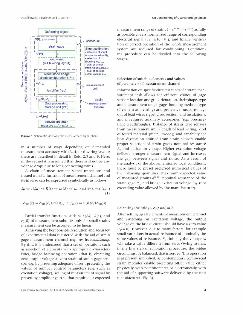
T (eout). Strain measurement signal undergoesa number of transformations from mechanicaldeformation input to electrical voltage output inthe process of measurement. The stages of thesetransformations are schematically shown in Fig. 1.Upon mechanical loading, a segment of some initiallength l0 deforms—elongates or shortens, by adistance �l. A change of length, �l, of strain gagebonded to the specimen surface induces change ofits relative resistance, �R/R. Variation of resistanceof a gage connected in a balanced Wheatstone bridgecircuit expresses itself as a nonzero-reduced voltagee0/Eex on the output of the bridge, where Eex denotesbridge excitation voltage. The small voltage on bridgeoutput is linearly gained by operational amplifier toobtain normalized voltage eout = Ku · e0 on output ofmeasurement channel, where constant Ku denotesoverall gain of operational amplifier(s). This outputvoltage is then processed to obtain strain value ε.
Special care must be undertaken when strain gageis located at long distance from bridge measurementunit, as resistance of connection wires resultsin voltage drops. This problem can be remedied
2 Experimental Techniques (2014) © 2014, Society for Experimental Mechanics
A. Ziołkowski, J. Luckner, and L. Dietrich On Conditioning of Quarter Bridge Circuit
Figure 1 Schematic view of strain measurement signal chain.
in a number of ways depending on demandedmeasurement accuracy with 3, 4, or 6 wiring layout;these are described in detail in Refs. 2,3 and 9. Here,in the sequel it is assumed that there will not be anyvoltage drops due to long connecting wires.
A chain of measurement signal transitions andnested transfer function of measurement channel andits inverse can be expressed symbolically as follows:
�l ↔ ε (�l) ↔ R (ε) ↔ e0 (R) ↔ eout (e0) ⇔ ε = ε (eout)
(1)
eout (ε) = eout (e0 (R (ε))) , ε (eout) = ε (R (e0 (eout))) .
Partial transfer functions such as ε(�l), R(ε), ande0(R) of measurement subunits only for small strainsmeasurement can be accepted to be linear.
Achieving the best possible resolution and accuracyof experimental data registered with the aid of straingage measurement channel requires its conditioning.By this, it is understood that a set of operations suchas selection of elements with appropriate character-istics, bridge balancing operation (that is, obtainingzero output voltage at zero strain of strain gage sen-sor; e.g. by presetting adequate offset), presetting thevalues of number control parameters (e.g. such asexcitation voltage), scaling of measurement signal bypresetting amplifier gain so that required or expected
measurement range of strains 〈− εmax, + εmax〉 as fullyas possible covers normalized range of correspondingelectrical signal (i.e. ±10 [V]), and finally verifica-tion of correct operation of the whole measurementsystem are required for conditioning. Condition-ing procedure can be divided into the followingstages.
Selection of suitable elements and valuesof parameters of measurement channel
Information on specific circumstances of a strain mea-surement task allows for efficient choice of gagesensors location and grid orientation, their shape, typeand measurement range, gages bonding method (typeof cement and curing) and protective measures, lay-out of lead wires (type, cross section, and insulation),and if required auxiliary accessories (e.g. pressure-tight feedthroughs). Distance of strain gage sensorsfrom measurement unit (length of lead wiring, kindof tested material [metal, wood]) and capability forheat dissipation emitted from strain sensors enableproper selection of strain gages nominal resistanceR0 and excitation voltage. Higher excitation voltagedelivers stronger measurement signal and increasesthe gap between signal and noise. As a result ofthe analysis of the abovementioned local conditions,there must be preset preferred numerical values ofthe following quantities: maximum expected valueof measured strains εmax, nominal resistance of thestrain gage R0, and bridge excitation voltage Eex (notexceeding value allowed by the manufacturer).
Balancing the bridge, e0(ε = 0) = 0
After setting up all elements of measurement channeland switching on excitation voltage, the outputvoltage on the bridge circuit should have a zero value(e0 = 0). However, due to many factors, for examplesmall variations in actual resistance of nominally thesame values of resistances Rα, initially the voltage e0
will take a value different from zero. Owing to that,in the first step of calibration procedure, the bridgecircuit must be balanced, that is zeroed. This operationis at present simplified, as contemporary commercialstrain modules enable presetting offset value eitherphysically with potentiometer or electronically withthe aid of supporting software delivered by the unitmanufacturer (Fig. 3).
Experimental Techniques (2014) © 2014, Society for Experimental Mechanics 3
On Conditioning of Quarter Bridge Circuit A. Ziołkowski, J. Luckner, and L. Dietrich
Shunt calibration/scaling procedure of measurementchannel checking that everything works properly
Matching of strain measurements range,〈− εmax, + εmax〉, with nominal range of outputelectric signal 〈 − 10, + 10〉 [V] and thus obtainingthe best resolution of measurements is assured bypresetting proper value of operational amplifier gainKu. The value of gain Ku specific for particular mea-surement conditions is very frequently determinedwith the aid of shunt calibration or scaling procedure.The same procedure serves for checking proper andaccurate operation of the whole strain measurementchannel which terminates initial steps for actualstrain measurements.
Decoding of strain value from measurementchannel output voltage requires knowledge of explicitform of the overall transfer function eout = f T(ε) in thecase of moderate strain measurements. This issue isdiscussed in the following sections.
Strain Measures for Moderate/Large Strain GageMeasurements
The concept of strains proved to be very useful in thedescription of deformations of any material body. Itemploys three elements: actual configuration, referenceconfiguration, and strain measure function. Althoughreference configuration can be selected at will, asreference configuration it is usually selected initialconfiguration (undeformed). A popular family of 3Dstrain measures finding widespread use at present intheoretical, numerical, and experimental mechanicsis defined as follows:
E(m) = (Um − I
)/m, m �= 0, E(0) = ln (U) , m = 0
(2)
F ≡ dx/dX, F = RU = VR; U = (FTF
)1/2
=∑
λi ui ⊗ ui, V = (FFT)1/2 =
∑λivi ⊗ vi
where F denotes the deformation gradient, xthe position vector of a material point in actualconfiguration, X the position vector of material pointin reference (initial) configuration, I the second-orderunit tensor, U and V the right and left stretch tensorsresulting from polar decomposition of deformationgradient, λi; i = 1, 2, and 3 are common forboth stretch tensors principal stretches—eigenvaluesof stretch tensors, ui, vi; i = 1, 2, 3 denotematerial (Lagrangian) and spatial (Eulerian) principaldirections of stretch tensors U and V. R is the
orthogonal polar rotation (material rotation) tensor(RTR = I).
All the most popular Lagrangian (‘‘embed-ded’’ in reference, configuration) strain mea-sures belong to this family, for example E(2) ≡0.5 (U2 − I) = 0.5 (FTF − I) the Green Lagrange strain,E(0) ≡ ln(U) the logarithmic (Hencky) strain, orE(1) = U − I the Biot strain. The corresponding Eule-rian (‘‘embedded’’ in actual configuration) strainmeasures can be obtained by replacement of rightstretch tensor with the left one in Eq. 21, forexample Eulerian logarithmic strain is e(0) = ln (V) =∑
ln (λi)vi ⊗ vi. Neither nominal strain tensor (non-
symmetric) E(N) ≡ F − I, nor small strains tensorE(s) ≡ 0.5 (F + FT − 2I) —also called technical or engi-neering strain—does satisfy the requirements posedon the tensor strain measure appropriate for describ-ing large deformations, as they are not invariant undermaterial rotation due to the presence of rotation ten-sor R in their definitions (Eq. 23).
Upon spectral decomposition of deformation-gradientLagrangian strain measures (Eq. 2) and their Euleriancounterparts can be expressed with family ofscalar so called scale functions of principal stretchesf (λi)
E(m) =∑
f (λi)ui ⊗ ui,
e(m) = RE(m)RT =∑
f (λi)vi ⊗ vi
f (λi) = ((λi)
m − 1)/m, m �= 0, f (λi) = ln (λi) , m = 0
(3)The scale functions have the properties f (λi)|λi=1 =
0 and df (λi) /dλi|λi=1 = 1. It is clear that strainmeasures from Eqs. 2 and 3 are completely equivalentand can be recalculated from one to the other ifonly all components of deformation gradient F areknown in some coordinates frame—this is usuallynot the case in resistive strain gage test method unlesssome additional assumptions are made besides actualexperimental measurements.
When deformations are small usually rotationtensor is close to unit tensor (R ∼= I), and then threestrain measures, small, nominal, and Biot becomefully equivalent E(s), E(N) R∼=I−−−→ U − I = E(1). It isclear that Biot strain makes a natural, properlydesigned extension of small strains tensor conceptinto moderate/large deformations. In order to avoidambiguities in nomenclature we will use here a termtechnical strain to mean small, nominal, and Biot strainmeasures when deformations are small, and to meanBiot strain measure when deformations are moderateor large.
4 Experimental Techniques (2014) © 2014, Society for Experimental Mechanics
A. Ziołkowski, J. Luckner, and L. Dietrich On Conditioning of Quarter Bridge Circuit
Hill11 relying on the presumption that total work indeformation process cannot depend on the way of itsdescription—remains invariant under change of strainmeasure—introduced the concept of stress measureT(m) work conjugate to any Lagrangian strain measureE(m) from the family of Eq. 2 as follows:
ρ0w = tr (τd) = tr(T(m) E(m)
) ; τ ≡ J σ = (ρ0/ρ) σ ,
d ≡ 0.5(L + LT) (4)
J ≡ det (F) = dv/dV = ρ0/ρ, L ≡ ∂v/∂x = FF−1;v = dx/dt nda = JF−TN dA
where ρ0 is density in reference configuration, w isspecific work (per unit of mass), τ is Kirchoff stress,J is determinant of deformation gradient, ρ is densityin reference configuration, σ denotes Cauchy stress, dis the deformation velocity tensor—rate of stretchingtensor, L is the velocity gradient tensor, T(m) is stressmeasure work conjugate to strain measure E(m),and the over-dot operation denotes usual materialderivative.
Base free–index free, formulas for stress measureT(m) work conjugate to E(m) are rather complicatedexcept for a few cases. It can be shown that thefollowing measures of stress and the strain are workconjugated in the sense of Hill
ρ0w = tr(σ (1)E(1)
) = tr(σ (2)E(2)
) ;ρ0w = tr
(σ (N)F
) = tr(σ (IPK)FT) (5)
σ (1) = 0.5(σ (2)U + Uσ (2)
), σ (2) = J F−1σ TF−T,
σ (IPK) = Jσ TF−T, σ (N) = J F−1σ = σ (IPK) T
where σ , σ (1), σ (2), σ (N), and σ (IPK) denote theCauchy, Biot, II Piola-Kirchoff, Nominal, and IPiola-Kirchoff stress tensors, respectively. Thus Biotstress is work conjugate to Biot strain, II Piola-Kirchoff stress to Green-Lagrange strain regardless ofmaterial symmetry— isotropic or anisotropic. Nominalstress is work conjugate to nominal strain but asindicated earlier this strain measure is not properlydefined to describe large deformations. It can alsobe shown that ρ0w = tr
(τ e(0)
)for isotropic materials.
This means that Kirchoff stress τ is work conjugate toEulerian logarithmic strain e(0) in the case of isotropicmaterials.
All force-deformation processes can be described infully equivalent, physically consistent manner withthe aid of whichever, freely selected work-conjugatepair of stress and strain measure tensors—theirrespective components. Using such pair in preparation
of experimental stress–strain curves assures that thearea under respective curves has the physical meaningof work of deformation.
In principle, all strain measures from familyof Eqs. 2 and 3, Lagrangian or Eulerian can beused interchangeably to describe large deformationsprocess in large deformation resistive strain gagetest method. Selection of particular strain measureis dictated by efficiency, specific needs, or simplicityof mathematical expressions. For example, in finiteelement method (FEM) of numerical computations,the Green-Lagrange strain measure is frequently usedbecause it allows to attain versatility and numericalefficiency, as it is easy to compute the value ofstress measure and work conjugate to it (σ (2)) fora material of any symmetry, and no costly spectraldecomposition of deformation gradient is needed foreach time step to compute actual value of Green-Lagrange strain. A disadvantage of this measureis its spherical and deviatoric part that describesdilatational and distortional effects in a coupledway. Only logarithmic strain measure has valuableproperty in which its spherical part describes purelydilatational deformation of the material element,while its deviatoric part describes purely distortionaldeformation at finite deformations as in E(0) =13 ln (J) 1 + dev
(E(0)
).6
Discussion of many subtleties of finite deformationsdescription goes beyond the scope of this work.Instructive presentation of invariances (under changeof strain measure and/or reference configuration) indescription of elastic–plastic deformation of metallicmaterials can be found in Refs. 6 and 7 Anillustrative, comparative study of simple shear test(plane stress conditions—generalized plane strain)of a specimen made of isotropic metal- andrubber-like materials containing explicit formulasdescribing the deformation process in several workconjugate stress–strain pairs can be found inRef. 8.
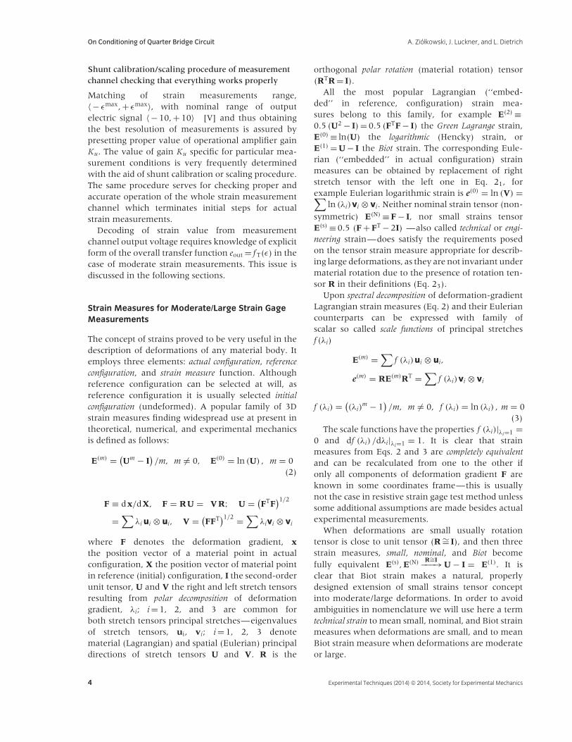
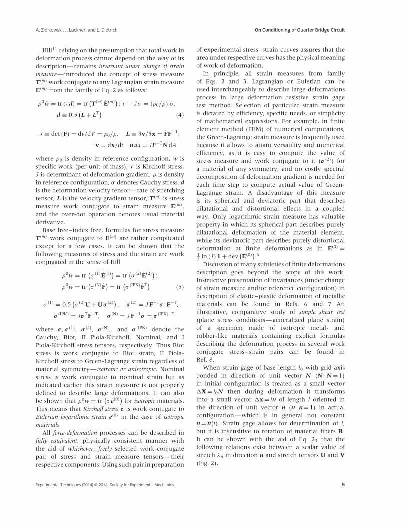
When strain gage of base length l0 with grid axisbonded in direction of unit vector N (N · N = 1)in initial configuration is treated as a small vector�X = l0N then during deformation it transformsinto a small vector �x = ln of length l oriented inthe direction of unit vector n (n · n = 1) in actualconfiguration—which is in general not constantn = n(t). Strain gage allows for determination of l,but it is insensitive to rotation of material fibers R.It can be shown with the aid of Eq. 23 that thefollowing relations exist between a scalar value ofstretch λn in direction n and stretch tensors U and V(Fig. 2).
Experimental Techniques (2014) © 2014, Society for Experimental Mechanics 5
On Conditioning of Quarter Bridge Circuit A. Ziołkowski, J. Luckner, and L. Dietrich
Figure 2 Schematic representation of large deformation kinematics
during resistive gage strain measurement.
λ2n = N· U2N = n· V2n ⇔ λn = n· Vn; λn ≡ l/l0,
n = RN, U = RTVR (6)
l2 = l2n· n = �x·�x = �X· FTF�X = �X· U2�X
= (l0 N) · U2 (l0 N) = (N· U2N
)l20
From the above it is clear that single grid straingage allows acquiring experimentally single value ofdirectional stretch λn. A strain gage does not allowfor measurement (registration) of rotation tensorR. Thus, it is impossible to determine right stretchtensor U, and/or F with resistive strain gages, onlycomponents of left stretch tensor V can be determined(Eq. 62).
Let us introduce two definitions, designations ofscalar strain measures based on stretch λn frequentlyencountered in engineering practice
εt ≡ λn − 1 = (l − l0) /l0 = �l/l0,
εLn ≡ ln (λn) = ln (l/l0) ; λn ≡ l/l0 (7)
εLn = ln (1 + �l/l0) = ln (1 + εt) , εt = exp (εLn) − 1
Expansion of natural logarithm into power seriesshows that for small strains, in the elastic rangeof metallic materials behavior, with excellent accu-racy εLn
∼= εt (power expansion of logarithm εLn =ln (1 + εt) = εt − 1
2ε2t + 1
3ε3t − 1
4ε4t + · · · ; |εt| < 1).
The following connections exist between compo-nents of Eulerian strain measures from family ofEq. 32 and directional stretch λn (Eq. 61,2).
e(1)nn = n· e(1)n = n· Vn − n· n = λn − 1 = εt,
e(2)nn = n· e(2)n = 1
2
(n· V2n − n· n
) = 1
2
(λ2
n − 1)
(8)
εLn = ln (n· Vn) �= n· ln (V) n = n· e(0)n = e(0)nn
Stress and/or strain analysis during research anddevelopment works frequently involves concurrentexperimental strain gage measurements and largedeformations FEM simulations. According to Eq. 8, forverification purposes, experimental strain εt should becompared with numerically determined projection ofEulerian Biot strain e(1)
nn , or experimental expression12
(λ2
n − 1)
should be compared with e(2)nn , that is
projection on direction n of numerically obtainedEulerian Green-Lagrange strain. It is interesting tonote that 2e(2)
nn = 2εt + ε2t .
In general case, there is no simple connectionbetween scalar logarithmic strain εLn —also called true,natural or Hencky strain, and projection of Eulerianlogarithmic strain on direction n (εLn �= e(0)
nn ; Eq. 83). Inorder to determine experimental value of logarithmicstrain tensor e(0) —its components or projectionsin fixed coordinate frame—all components ofstretch tensor V must be known from experimentalmeasurements. In the case of plane strain deformationfor example, in order to determine three unknowncomponents of stretch V, three noncollinear stretchesλn1, λn2, λn3 must be measured—for example withthree grids strain gage. Upon solving a set of threealgebraic equations using λni = ni · Vni; (i = 1, 2, 3),actual value of tensor e(0) and its projection e(0)
nn canbe determined (Eq. 83).
When one of the targets of the analysis islocal material behavior, full information on stretchtensor V is also required. Its value is necessaryfor determination of the value of work conju-gate stress measures, that is rotated Biot stressRσ (1)RT = 1
2 J(V−1σ + σV−1
)in the case of Eule-
rian Biot strain e(1) and rotated II Piola Kirchoffstress Rσ (2)RT = J V− 1σV− 1 in the case of EulerianGreen-Lagrange strain e(2). The area under chartσ t − εt has the physical meaning of the work ofdeformation, regardless of material symmetry whichcould be anisotropic, where σt = n· (Rσ (1)RT
)n =
n· 12 J
(V−1σ + σV−1
)n.
The scalar logarithmic strain εLn exhibits usefulproperty of additiveness, that is upon summingup several consecutive strain measurements ofdeforming material the same value is obtained asif measurement has been done in a single step (Eq.9a). Technical strain εt does not possess this property(Eq. 9b).
ε1Ln + ε2
Ln + ε3Ln = ln (l1/l0) + ln (l2/l1) + ln (l/l2)
= ln ((l/l2) · (l2/l1) · (l1/l0)) = ln (l/l0) = εLn
(9a)
6 Experimental Techniques (2014) © 2014, Society for Experimental Mechanics
A. Ziołkowski, J. Luckner, and L. Dietrich On Conditioning of Quarter Bridge Circuit
ε1t + ε2
t + ε3t = (l1 − l0) /l0 + (l2 − l1) /l1 + (l − l2) /l2
�= (�l1 + �l2 + �l3) /l0 = �l/l0 = εt
(9b)
In a special case of moderate or large strainsimple tension (extension) test principal directions ofdeformation remain constant. Then for isotropicmaterials work conjugate components of tensorialstress and strain measures (τ − e(0)) are scalarlogarithmic strain εLn and scalar Kirchoff stressτ . It is a well-known experimental fact thatmetallic materials flow plastically without changein volume (V 0 = V , A0l0 = Al) and behave likeincompressible material. Taking advantage of suchbehavior uniaxial Cauchy stress value σ can bedetermined with very good accuracy withoutmeasuring actual cross section area (A) using the for-mula σ = F/A = σ n A0/A = (1 +�l/l0) σ n = (1 + εt) σ n;where σ n ≡ F/A0 is nominal stress and A0 is initialcross section of a specimen. Upon the same incom-pressibility condition, uniaxial Kirchoff stress is equalto Cauchy stress τ = (V/V 0)σ = σ (Eq. 42), at simpletension of metallic materials. Thus, the area understress–strain curve σ − εLn has the physical meaningof work of deformation and correctly describesconstitutive properties of tested material.
Overall Transfer Function of Measurement Systemin the Case of Large Strains
For purposes of the discussion of the present section,it has been adopted that three assumptions arevalid: (1) electrical resistance of strain gage metallicgrid material is related to its length and crosssection by Kelvin law (); (2) strain gage metallicgrid material behaves in an incompressible wayin plastic deformation regime (); (3) influence ofplastic deformation on variation of specific electricalresistivity of strain gage metallic grid material in plasticdeformation regime can be neglected ().
Resistive strain gage sensor transferfunction—�R/R0(ε)
Physically resistive gage technology is based on therelationship discovered by Kelvin linking electricalresistance with metallic wire length
R = ρel l/A (10)
where R denotes conductor resistance in ohms [],ρel is specific resistivity in [m], l is wire conductorlength [m] and A is conductor cross section area
[m2]. Initially strain gage has nominal resistanceR0 = ρel l0/A0. Commercially, there are available seriesof types of gages with various nominal resistances.Most frequently in metal deformation measurementsthe gages with a nominal resistance of 120 or350 ohms [] are used. Assumption 1 is accepted herethat relation in Eq. 10 is valid for moderately largedeformations. Upon differentiation Eq. 10 results inthe following:
dR/R = dρel /ρel+ dl/l − dA/A, or
dR/R = dρel /ρel+ 2dl/l − dV/V (11)
Linearly elastic, isotropic materials at simpletension change volume in accordance with theformula dV/V = (1 − 2v)dl/l. When linear elastic,isotropic, metallic material of strain gage grid operatesin small strain regime, that is in its elastic rangeof behavior then upon introducing the recentvolume change expression into Eq. 112, dR/R =dρel /ρel + (1 + 2v)dl/l is obtained.
Originating from Kelvin’s law, relation in Eq. 112 isnot used in practice for small strains measurements, asit is difficult to accurately evaluate variation of specificelectric resistivity term dρel /ρel, which is itself a func-tion of deformation in an elastic range of strain gagemetallic grid behavior—chapter 9 of Watson.1 Insteadactual strain gage characteristic is determined exper-imentally, for example in accordance with guidelinesof ASTM-E251 standard.1 In small strains gage cali-bration procedure a constant of proportionality GFis determined—called gage factor—which enters tem-plate formula as follows:
�R/R0 = GF·�l/l0 = GF· εt (12)
Manufactures of strain gages specify the value ofgage factor in a leaflet accompanying any specific typeof a strain gage sold by them.
Let us return to Kelvin law. In moderate orlarge strain measurements, it is reasonable to acceptAssumption 2 that strain gage metallic grid material,operating in plastic deformation regime, behavesin incompressible way dV/V = 0 (dl/l + dA/A = 0).Under plastic deformation of strain gage metallic gridmaterial also Assumption 3 is very well justified thatchange in its specific electrical resistivity is negligible(dρel /ρel = 0). Upon these conjectures the following
Experimental Techniques (2014) © 2014, Society for Experimental Mechanics 7
On Conditioning of Quarter Bridge Circuit A. Ziołkowski, J. Luckner, and L. Dietrich
relations are valid (Eq. 112)
dR
R= 2dl
l,
l∫l0
dR
R=
l∫l0
2dl
l⇔ ln
(R
R0
)= 2 ln
(l
l0
)
= 2εLn,R
R0=
(l
l0
)2
(13)
(1 + �R/R0) = (1 + �l/l0)2 , �R/R0 = (1 + εt)
2 − 1
= 2εt + ε2t , �R/R0 = exp (2· εLn) − 1
In obtaining Eq. 136 relation in Eq. 75 hasbeen used. From Eq. 132 it can be concludedthat sensitivity of strain gage metallic grid relativeelectrical resistance with respect to scalar logarithmicstrain is constant and equal to 2 in plastic rangeof grid deformation ((1/R)(dR/dεLn) = 2). Comparinglinear template relation �R/R0 = GF · εt adopted forsmall deformations measurements with relations inEq. 132 or 136 valid for moderate or large strainmeasurements upon Kelvin law, it is clear that thebest matching of characteristics is obtained, no kinkon transition from elastic to plastic range, if straingage used for moderate or large strain measurementshas gage factor as close to 2 as possible. In factthe most popular strain gages with grid made ofconstantan have gage factor very close to the valueof 2. While conjectured here Assumptions 1–3 arerealistic based on state-of-the-art knowledge and it ishighly recommended to execute further systematicexperimental studies of strain gage metallic gridmaterial’s behavior targeted at determination of theirelectric resistance variation as a function of moderateor large strains.
Wheatstone bridge in quarter bridge configurationsignal transfer function—e0/Eex(�R/R0)
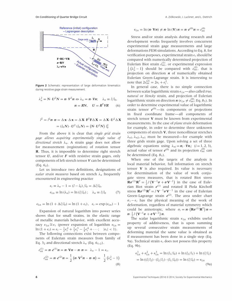
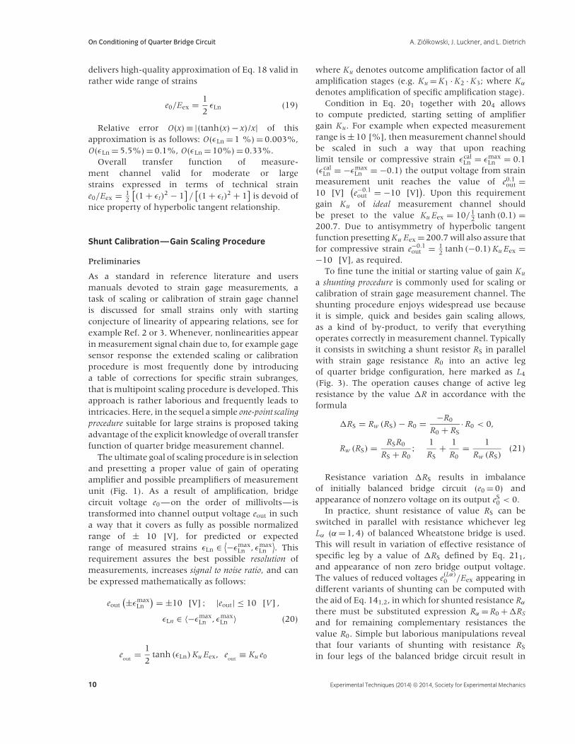
The Wheatstone bridge circuit has gained applicationin resistance strain gages technology because it isvery sensitive in detecting and tracking of verysmall variations of voltage (0.01 [V]) resulting fromminiscule variation of strain gage resistance, onthe order of 10th of Ohm. Strain measurementconfiguration with Wheatstone bridge circuit inquarter bridge layout is shown in Fig. 3. ResistorR0 (R4) represents nominal resistance of a strain gagesensor—the most commonly encountered strain gagesensors have nominal resistance of 120 or 350 [].Resistors R1, R2, and R3 are completing resistors ofthe bridge placed in its nonactive legs.
Figure 3 Schematic view of strain gage measurement layout with only
one active leg—quarter bridge configuration.
Excitation voltage Eex is usually within the rangeof 1 to 10 [V] (Eex ∈< 1, 10 > [V]). Values of bridgeoutput voltage e0 varying with strain ε detected bystrain gage sensor are on the level of millivolts.Due to that the measurement signal e0 has to beamplified with operating amplifiers to bring it tostandardized range eout ∈< − 10, 10 > [V], where eout
denotes standardized output of measurement channelon output of measurement unit (Fig. 1).
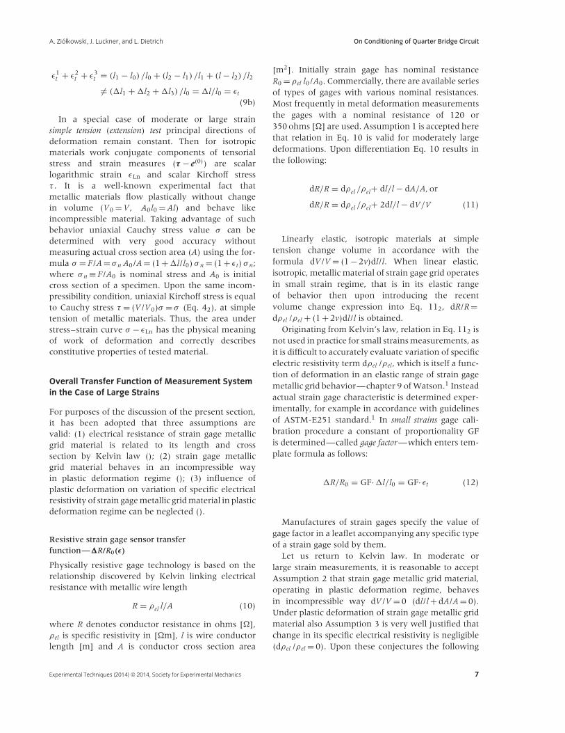
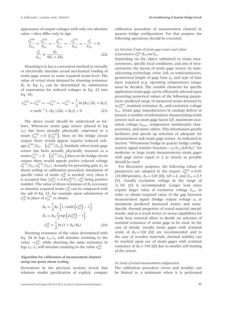
It is worth mentioning that contemporary com-mercial strain gage modules are quite sophisticatedand equipped with a number of features enablingmitigation of adverse conditions negatively influ-encing measurement accuracy. For example straingage module of Measurement Computing Company(Fig. 4), recalled after Fig. 7.05 in Ref. 9, provides foreach measurement channel the capability for adjust-ing excitation voltage, bridge offset, and amplificationgain. The six-wire connection feature enables auto-matic stabilization of a value of excitation voltage andcompensation for voltage drop on lead wires. How-ever, due to economical reasons three-wire layout isencountered much more frequently in engineeringpractice, ensuring simply compensation for differ-ence in lead wires resistance and change of resistancedue to temperature variations along the lead wires(section 1.5.2 in Ref. 3). Electronics and softwareof modern strain gage modules allow for very easyimplementation of calibration method discussed inthis work in the sequel.
Upon Ohm’s law, the following relations must befulfilled (R1 + R4) · i1 = Eex, (R2 + R3) · i2 = Eex (Fig. 3).Then simple manipulations lead to the follow-ing expressions for output voltage of Wheatstonebridge e0,
e0
Eex= R4
R4 + R1− R3
R3 + R2,
e0
Eex= R2
R3 + R2− R1
R1 + R4(14)
e0 ≡ R4i1 − R3i2 = R2i2 − R1i1
8 Experimental Techniques (2014) © 2014, Society for Experimental Mechanics

A. Ziołkowski, J. Luckner, and L. Dietrich On Conditioning of Quarter Bridge Circuit
Figure 4 Schematic diagram of one
channel of state-of-the-art commercial
strain gage module enabling
compensation for excitation voltage
drop, presetting offset, adjustment of
gain, and thus very accurate
measurements, after measurement
computing.9
Balancing of the bridge, expressed mathematicallywith equality e0 = 0, requires that the followingcondition of proportionality must be fulfilled
e0 = 0 ⇔ R4
R1= R3
R2(15)
The values of resistors Rα completing straingage measurement circuit are usually selected tomatch the nominal value of gage sensor resistanceR0 = R1 = R2 = R3. Balanced measurement channelhas the property that the bridge output voltagetakes the value of zero (e0 = 0), when strain is zero(ε = 0).
In accordance with Eq. 141, a change by �R innominal resistance of strain gage connected in quarterbridge configuration (Fig. 3), will result in appearanceof nonzero value of reduced voltage on the outputof initially balanced bridge (R0 = R1 = R2 = R3) asfollows:
e0
Eex= R0 + �R
R0 + �R + R0− 1
2= 1
2
12�R/R0(
1 + 12�R/R0
) ,
�
RR0 = 2
2e0/Eex
(1 − 2e0/Eex)(16)
In the case of tensile strains (�R > 0) the voltagee0 takes positive values, while in the case ofcompressive strains (�R < 0) the voltage e0 takesnegative values. For example, when strain gagewith nominal resistance R0 = 120 [] and GF = 2is submitted to small tension strain of offset yieldstrain εt = 0.002 (2000 μstrains; 1 μstrain = 1 ·10−6),then its electrical resistance will change as per Eq.12 by �R = 2 · 120 · 0.002 = 0.48 [] (�R/R0 = 0.004).
Such change of resistance will induce reduced voltagee0/Eex on the bridge circuit output of 1 millivolt volt−1
(e0/Eex = 1 · 10− 3 [V/V]).In many cases of stress (strain analysis) metallic
structure operates only in elastic envelope ofdeformation. Upon substituting gage sensor responsein Eq. 12 (εt < 0.002) into bridge circuit transferfunction in Eq. 16 (�R/R0 ≤ 0.004) and neglectinghigher than linear terms, the well known small strainslinear quarter bridge formula is recovered
e0/Eex = 1
4GFεt
(e0/Eex = 1
4�R/R0
)(17)
Please note that Assumptions 1–3 conjectured inprevious section concern strain gage grid metallicmaterial and not materials for which strains aremeasured.
Overall transfer function of measurement channel
Elimination of �R/R0 in Eq. 161 with the aidof Eq. 136 leads to the following relationships,under Assumptions 1, 2, and 3 made in the abovesection, that are valid for moderate or large strainmeasurements
e0
Eex= 1
2
exp (2· εLn) − 1
(exp (2· εLn) + 1)= 1
2tanh (εLn) ,
εLn = tanh−1 (2e0/Eex) ≡ 1
2ln
(1 + 2e0/Eex
1 − 2e0/Eex
)
(18)
It is interesting to note that in power seriesexpansion of hyperbolic tangent no quadratic term ispresent—tanh (εLn) = εLn − 1
3ε3Ln + 2
15ε5Ln + · · ·. This
Experimental Techniques (2014) © 2014, Society for Experimental Mechanics 9
On Conditioning of Quarter Bridge Circuit A. Ziołkowski, J. Luckner, and L. Dietrich
delivers high-quality approximation of Eq. 18 valid inrather wide range of strains
e0/Eex = 1
2εLn (19)
Relative error O(x) ≡ |(tanh(x) − x)/x| of thisapproximation is as follows: O(εLn = 1 %) = 0.003%,O(εLn = 5.5%) = 0.1%, O(εLn = 10%) = 0.33%.
Overall transfer function of measure-ment channel valid for moderate or largestrains expressed in terms of technical straine0/Eex = 1
2
[(1 + εt)
2 − 1]/[(1 + εt)
2 + 1]
is devoid ofnice property of hyperbolic tangent relationship.
Shunt Calibration—Gain Scaling Procedure
Preliminaries
As a standard in reference literature and usersmanuals devoted to strain gage measurements, atask of scaling or calibration of strain gage channelis discussed for small strains only with startingconjecture of linearity of appearing relations, see forexample Ref. 2 or 3. Whenever, nonlinearities appearin measurement signal chain due to, for example gagesensor response the extended scaling or calibrationprocedure is most frequently done by introducinga table of corrections for specific strain subranges,that is multipoint scaling procedure is developed. Thisapproach is rather laborious and frequently leads tointricacies. Here, in the sequel a simple one-point scalingprocedure suitable for large strains is proposed takingadvantage of the explicit knowledge of overall transferfunction of quarter bridge measurement channel.
The ultimate goal of scaling procedure is in selectionand presetting a proper value of gain of operatingamplifier and possible preamplifiers of measurementunit (Fig. 1). As a result of amplification, bridgecircuit voltage e0 —on the order of millivolts—istransformed into channel output voltage eout in sucha way that it covers as fully as possible normalizedrange of ± 10 [V], for predicted or expectedrange of measured strains εLn ∈ ⟨−εmax
Ln , εmaxLn
⟩. This
requirement assures the best possible resolution ofmeasurements, increases signal to noise ratio, and canbe expressed mathematically as follows:
eout(±εmax
Ln
) = ±10 [V] ; |eout| ≤ 10 [V] ,
εLn ∈ 〈−εmaxLn , εmax
Ln 〉 (20)
eout
= 1
2tanh (εLn) Ku Eex, e
out≡ Ku e0
where Ku denotes outcome amplification factor of allamplification stages (e.g. Ku = K1 · K2 · K3; where Kα
denotes amplification of specific amplification stage).Condition in Eq. 201 together with 204 allows
to compute predicted, starting setting of amplifiergain Ku. For example when expected measurementrange is ± 10 [%], then measurement channel shouldbe scaled in such a way that upon reachinglimit tensile or compressive strain εcal
Ln = εmaxLn = 0.1
(εcalLn = −εmax
Ln = −0.1) the output voltage from strainmeasurement unit reaches the value of e0.1
out =10 [V]
(e−0.1out = −10 [V]
). Upon this requirement
gain Ku of ideal measurement channel shouldbe preset to the value Ku Eex = 10/ 1
2 tanh (0.1) =200.7. Due to antisymmetry of hyperbolic tangentfunction presetting Ku Eex = 200.7 will also assure thatfor compressive strain e−0.1
out = 12 tanh (−0.1) Ku Eex =
−10 [V], as required.To fine tune the initial or starting value of gain Ku
a shunting procedure is commonly used for scaling orcalibration of strain gage measurement channel. Theshunting procedure enjoys widespread use becauseit is simple, quick and besides gain scaling allows,as a kind of by-product, to verify that everythingoperates correctly in measurement channel. Typicallyit consists in switching a shunt resistor RS in parallelwith strain gage resistance R0 into an active legof quarter bridge configuration, here marked as L4
(Fig. 3). The operation causes change of active legresistance by the value �R in accordance with theformula
�RS = Rw (RS) − R0 = −R0
R0 + RS· R0 < 0,
Rw (RS) = RSR0
RS + R0; 1
RS+ 1
R0= 1
Rw (RS)(21)
Resistance variation �RS results in imbalanceof initially balanced bridge circuit (e0 = 0) andappearance of nonzero voltage on its output eS
0 < 0.In practice, shunt resistance of value RS can be
switched in parallel with resistance whichever legLα (α = 1, 4) of balanced Wheatstone bridge is used.This will result in variation of effective resistance ofspecific leg by a value of �RS defined by Eq. 211,and appearance of non zero bridge output voltage.The values of reduced voltages e(Lα)
0 /Eex appearing indifferent variants of shunting can be computed withthe aid of Eq. 141,2, in which for shunted resistance Rα
there must be substituted expression Rα = R0 +�RS
and for remaining complementary resistances thevalue R0. Simple but laborious manipulations revealthat four variants of shunting with resistance RS
in four legs of the balanced bridge circuit result in
10 Experimental Techniques (2014) © 2014, Society for Experimental Mechanics
A. Ziołkowski, J. Luckner, and L. Dietrich On Conditioning of Quarter Bridge Circuit
appearance of output voltages with only one absolutevalue—they differ only in sign
e(L4)0
Eex= e(L2)
0
Eex= − e(L3)
0
Eex= − e(L1)
0
Eex= − eS
0
Eex< 0;
eS0
Eex≡ R0
4RS + 2R0(22)
Shunting is in fact a convenient method to virtuallyor electrically simulate actual mechanical loading ofstrain gage sensor to some required strain level. Thevalue of virtual strain imitated by shunting resistanceRS in leg Lα can be determined by substitutionof expressions for reduced voltages in Eq. 22 intoEq. 182
ε(L4)Ln = ε
(L2)Ln = −ε
(L3)Ln = −ε
(L1)Ln = 1
2ln [RS/ (RS + R0)]
= tanh−1 [−R0/ (2RS + R0)] < 0 (23)
The above result should be understood as fol-lows. Whenever strain gage sensor (placed in legL4) has been actually physically compressed to a
strain ε(L4)Ln < 0
(ε
(L2)Ln
), then on the bridge circuit
output there would appear negative reduced volt-
age e(L4)0 /Eex
(e(L2)0 /Eex
). Similarly when strain gage
sensor has been actually physically tensioned to a
strain ε(L1)Ln > 0
(e(L2)0 /Eex
)then on the bridge circuit
output there would appear positive reduced voltagee(L1)0 /Eex (e(L3)
0 /Eex). Actually for presetting gain Ku inshunt scaling or calibration procedure simulation ofspecific value of strain εcal
Ln is needed, very often itis accepted that
∣∣εcalLn | ≈ 0.8 |εmax
ln
∣∣; εcalLn being positive
number. The value of shunt resistance of RS necessaryto simulate required strain εcal
Ln can be computed withthe aid of Eq. 23, for example upon substitution ofεcal
Ln in place of ε(L3)Ln to obtain,
RS = 1
2R0·
[1/ tanh
(εcal
Ln
)− 1
],
RS = R0/[exp
(2εcal
Ln
)− 1
],
εcalLn = 1
2ln (1 + R0/RS) (24)
Shunting resistance of the value determined withEq. 24 in legs L4, L2 will simulate straining to thevalue −εcal
Ln , while shunting the same resistance inlegs L3, L1 will simulate straining to the value εcal
Ln .
Algorithm for calibration of measurement channelusing one-point shunt scaling
Derivations in the previous sections reveal thatrelations enable specification of explicit, compact
calibration procedure of measurement channel inquarter bridge configuration. For that purpose thefollowing operations should be executed.
(a) Selection of type of strain gage sensor and valuesof parameters εmax
Ln ,R0,and Eex
Depending on the object submitted to strain mea-surements, specific local conditions, and aim of mea-surements the layout of strain gage sensor, its man-ufacturing technology (wire, foil, or semiconductor),geometrical length of gage base l0, and type of baselayer required (e.g. operating temperatures range)must be decided. The suitable elements for specificapplication strain gage can be efficiently selected uponpresetting numerical values of the following param-eters: predicted range of measured strain denoted by±εmax
Ln , nominal resistance R0, and excitation voltageEex. Strain gage manufacturers in catalogs deliver atpresent a number of information characterizing strainsensors such as strain gage factor GF, maximum exci-tation voltage Emax, temperature nonlinearity char-acteristics, and many others. This information greatlyfacilitates and speeds up selection of adequate formeasurement task strain gage sensor. As indicated inSection ‘‘Wheatstone bridge in quarter bridge config-uration signal transfer function—e0/Eex(�R/R0)’’ formoderate or large strain measurements strain gageswith gage factor equal to 2 as closely as possibleshould be used.
For illustrative purposes, the following values ofparameters are adopted in the sequel: εmax
Ln = 0.01(10,000 μstrain), R0 = 120 [], GF = 2, and Eex = 2.5[V]. Usually excitation voltage in the range of〈1, 10〉 [V] is recommended. Longer lead wiresrequire larger value of excitation voltage Eex, inorder to obtain required value of the gap betweenmeasurement signal (bridge output voltage e0 atmaximum predicted measured strain) and noise.Specific thermal properties of tested material (metal,wood), and as a result better or worse capabilities forJoule heat removal allow to decide on selection ofnominal resistance of strain gage to be used. In thecase of metals, usually strain gages with nominalstrain of R0 = 120 [] are recommended and inthe case of wooden materials, thermal stability canbe reached upon use of strain gages with nominalresistance of R0 = 350 [] due to smaller self-heatingof the sensor.
(b) Setup of actual measurement configuration
The calibration procedure errors and troubles canbe limited to a minimum when it is performed
Experimental Techniques (2014) © 2014, Society for Experimental Mechanics 11
On Conditioning of Quarter Bridge Circuit A. Ziołkowski, J. Luckner, and L. Dietrich
on actual physical measurement configuration. Firststrain gage should be bonded in required location andconnected with lead wires with preamplifiers and/ormeasurement unit in bridge circuit. The accuracy andquality of measurement results depend strongly onthe precision and quality of strain gage cementingprocedure. Gage bonding techniques and bondingmaterials are at present a wide branch of strain gagetest methods, discussion of which even casually goesbeyond the scope of this paper. It is worth noting,however, that the cement must be matched to thetype of substrate, durability of measurement, as wellas the predicted temperature range. For example verylow temperatures induce decrease of cement elasticityand can result in separation of strain gage.
(c) Balancing the bridge
Upon setting up measurement layout and switchingon excitation voltage it usually appears to be unbal-anced e0(εLn = 0) �= 0. It can be balanced physically toobtain e0(εLn = 0) = 0 [V] with the aid of potentiome-ter when measurement module is equipped with suchoption. Otherwise this can be done by presetting off-set in the software of measurement module. Initialunbalancing usually results from small variation ofnominal equal resistances of complementary resistorsof bridge circuit and/or unequal length of lead wires.
(d) Selection of shunt resistor RS (↔ εcalLn )
It is usually recommended that shunt resistor RS issuch that after shunting it in selected leg of bridgecircuit, Lα, it simulates virtual straining of straingage sensor, here assumed to be located in leg L4
(Fig. 3), to about 80% of maximum expected strainvalue, εcal
Ln ≈ ±0.8εmaxLn . Definite value of simulated
strain is of lesser significance but it is necessarythat shunt resistor RS must be of high quality andstability. Required accuracy of shunt resistor RS
depends on nominal value of strain gage, excitationvoltage, and required accuracy of measurements, forexample 0.01 [V] of eout. It can be estimated, fromcondition |�eout/�RS| ≤ 0.01 using the relationshipe(L4)out = −KuEexR0/ (4RS + 2R0) that originated from
Eqs. 22 and 205. Precision of shunt resistor influenceseffectiveness of calibration procedure, which is doneby matching the actual measured value of outputvoltage eout appearing when equilibrated bridgecircuit is shunted with resistor RS with the voltagevalue predicted by Eq. 26. When the value ofcalibration strain is decided, the value of requiredshunt resistance RS
(εcal
Ln
)to simulate strain εcal
Ln canbe determined by Eq. 24. For example when εmax
Ln =
0.01, then simulation of compressive strain −εcalLn =
−0.8εmaxLn = −0.008 requires shunting leg L4 (or L2)
with resistance RS = 120/[exp(2 · 0.008) − 1] = 7440[] (R0 = 120). The same resistance shunted in leg L1
(L3) will simulate tensile strain εcalLn = 0.008. In this
specific case accuracy of ± 1 [] of RS is sufficient toobtain accuracy of eout better than 0.01 [V].
(e) Determination and presetting the values of amplifiers gain
Ku
The predicted, starting value of operational amplifiersetting Ktr
u can be determined upon one-point scalingcondition eout
(−εmaxLn
) = −10 [V] (Eq. 20),
Ktru = 20/
[Eex· tanh
(εmax
Ln
)](25)
Calculated from Eq. 25 value of total gain Ktru
should be input into relevant field of software ser-vicing strain gage module. In software of somemanufacturer’s total gain can be split into sev-eral positions, for example gain of preamplifier,main gain, and fine tuning gain. Accepting val-ues of parameters of illustrative case that startedin point (a), εmax
Ln = 0.01, Eex = 2.5 [V], startingvalue of total gain is Ktr
u = 20/ [2.5· tanh (0.01)] =800.0
(Ktr
u Eex = 2000.0 [V]).
If measurement channel would be ideal then uponpresetting measurement software total gain value toKtr
u and shunting leg Lα with shunt resistor in Eq. 24to simulate calibration strain in Eq. 23 there shouldappear nonzero output voltage of the followingvalue
eout = 1
2tanh
(εcal
Ln
)Ktr
u Eex,
eout = 10 tanh(εcal
Ln
)/ tanh
(εmax
Ln
)(26)
Equation 262 has been obtained from Eq. 261 withthe aid of Eq. 25. Returning to the discussed specificcase shunting of RS = 7440 [] in leg L4 results ineout =− 8.00 [V] (−εcal
Ln = −0.008), and shunting it inleg L1 results in eout = +8.00 [V]
(εcal
Ln = 0.008).
Actual voltage read on the output of strain gagemodule will usually deviate from the value predictedby Eq. 26 because of various types of inaccuracies,or losses of real physical layout, for example notideally matched values of balancing resistances Rα.In such a case, the value of setting Ktr
u → Ku shouldbe changed until actual and predicted values by Eq.26 of output voltage agree with desired accuracy, forexample ±0.01 [V]. Whenever measurement channelis properly put together and it consists of good qualityelements then such fine tuning corrections should beminute.
12 Experimental Techniques (2014) © 2014, Society for Experimental Mechanics
A. Ziołkowski, J. Luckner, and L. Dietrich On Conditioning of Quarter Bridge Circuit
(f) Verification of calibration procedure
It is advisable to verify calibration procedure. Thiscan be done by connecting shunt resistor withdifferent resistance or shunting the original resistorin different leg of bridge circuit. If different resistorR1
S is shunted in leg Lα —simulating strain ε1Ln in
accordance with Eq. 23, the output voltage ofmeasurement module should attain the value eout =10 tanh
(ε1
Ln
)/ tanh
(εmax
Ln
)—ε1
Ln = ε1Ln
(R1
S
)(Eq. 24).
(g) Recovering the strain value
Correctly scaled measurement channel allows forregistration of signals in the form of output voltagevalues, |eout| ≤ 10 [V]. The signals can be stored raw,and processed later to recover values of strains withthe aid of Microsoft Excel. The other possibilityavailable in contemporary electronic modules andservicing its software is to use ”computationalchannel” option, with the aid of which the valuesof strain can be obtained on line using the relationresulting from Eqs. 182 and 205,
εLn = tanh−1(
2eout
KuEex
)= 1
2ln
(1 + 2eout/ (KuEex)
1 − 2eout/ (KuEex)
)
(27)
As indicated in Eq. 19 when strain |εLn| ≤ 5.5 %(55000 μs), Eq. 27 can be replaced withεLn = 2eout/KuEex upon accepting relative errorless than 0.1%—O(εLn = 5.5 %) = 0.1 %).
Complete list of activities required for conditioningof strain measurement channel in quarter bridgelayout taking advantage of one-point shunt scalingor calibration procedure is compactly specified inTable 1.
Improvement of Moderate Strains MeasurementAccuracy
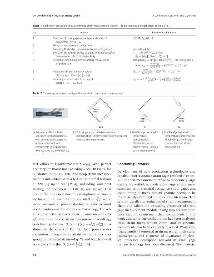
To elucidate developments of the previous sections,we present in this section a problem of improvingprecision of strain measurements, which arosein a research project devoted to testing of athermomechanical behavior of the Ni51%at-Ti shapememory alloy submitted to multiaxial loadings.Geometry of tubular specimen used in testingprogram is shown in photo placed in cell (a) of Table 2.An external and internal diameter of a specimen was19.0 and 16.0 mm, respectively. The gage length ofthe specimen was equal to 60.0 mm.
For thermomechanical testing, specimen has beenmounted in a biaxial universal testing machineequipped with temperature chamber using home
designed grips. A series of thermomechanical tests hasbeen executed. During each test specimen was firstcooled to specific low temperature at no mechan-ical load, next it was submitted to mechanicalloading–unloading cycle of simultaneous axial forceand torque at constant low temperature. Finally, thespecimen was heated to 330 [K] temperature at zeromechanical load. Three components of strain tensorwere measured: axial εz, hoop εθ , and shear εrθ . Allstrain components were measured in configurationswith temperature compensation as is schematicallyindicated in cells (b)–(d) of Table 2. Effectivelyshear strain was measured in half bridge configu-ration and axial and hoop strains in quarter bridgeconfigurations. The shear strain εrθ was measuredusing rosette strain gage of type EP-08-125RA-120,while axial and hoop strains were measured usingsingle grid strain gages of type EP-08-125DQ-120,the strain gages were produced by Vishay. One setof strain gages was bonded on mechanically loadedtest specimen, while the second was bonded on ref-erence specimen (not loaded mechanically) madeof the same NiTi material. The reference specimenwas placed in temperature chamber in vicinity oftest specimen so that both have the same tempera-ture during testing process. Nominally two types ofstrain gages used in testing program had a maxi-mum strain range of 0.2 (20%). The measurementsystem has been connected, and shunt scaled or cal-ibrated in accordance with conventional one-point‘‘small strains’’ calibration procedure using shuntresistor corresponding to calibration strain value ofεcal
t = 0.01 (1%). According to adopted program oftests the expected values of measured strain compo-nents amounted to 10.0 (10%). Actually, the level ofloadings has been decreased to prolong longevity ofspecimen and strains reached only 5%. The authorswere conscious of deterioration of strain measure-ments accuracy with increasing maximum value ofmeasured strain components during execution of theexperimental program due to measurement chaincomponents nonlinearities. However, only recentresults of this study delivered opportunity to improveaccuracy of the then obtained results. This has beenattained by first recovering signal �R/R0 using lin-ear relations of standard small strains calibration.Next this signal has been substituted in Eq. 136
to obtain correct, that is taking into account straingage and quarter bridge layout nonlinearities, val-ues of measured axial and hoop strains. Comparisonof Eqs. 17 and 19 reveals that the numerical valuesof strains interpreted under small strains calibrationprocedure to be technical strain values (εt) are in
Experimental Techniques (2014) © 2014, Society for Experimental Mechanics 13
On Conditioning of Quarter Bridge Circuit A. Ziołkowski, J. Luckner, and L. Dietrich
Table 1 Calibration procedure of quarter bridge strain measurement channel—to be repeated per each strain channel (Fig. 1)
No Activity Parameters, Relations
1 Selection of strain gage sensor type and values of
parameters εmaxLn ,R0,Eex
εmaxLn ,R0,Eex, GF = 2
2 Setup of measurement configuration3 Balancing the bridge, for example by presetting offset e0(ε = 0) = 0 [V]4 Selection of shunt resistance value RS for required εcal
Ln ; or
determination of εcalLn for available RS
RS ↔ εcalLn (εcal
Ln ≈ ±0.8εmaxLn )
RS = 12 R0·
[1/ tanh
(εcal
Ln
) − 1]
5 Prediction, fine tuning, and presetting the values of
amplifiers gain
Trial gain Ktru = 20/
[Eex tanh
(εmax
Ln
)]. Fine tuning gain Ku
until |eout = 10 tanh(εcal
Ln
)tanh(εmax
Ln )− emeasured
out | ≤ 0.01 [V].
6 Validation of calibration procedure(R1
S = 12 R0·
[1/ tanh
(ε1
Ln
) − 1]) |eout = 10·tanh
(ε1
Ln
)tanh(εmax
Ln )− emeasured
out | ≤ 0.01 [V]
7 Decoding of strain value from output
voltage—εLn = εLn(eout)
εLn = tanh−1(
2eoutKuEex
)≡ 1
2 ln(
1+2eout/(KuEex)
1−2eout/(KuEex)
)
Table 2 Tubular specimen and configurations of strain components measurement
(a) Geometry of NiTi tubular
specimen for multiaxial tests
with bonded strain gages for
measurement of three
components of strain tensor:
axial εz, hoop εθ , and shear εrθ .
(b) Full bridge layout with temperature
compensation. Effectively half bridge layout for
shear strain measurement.
(c) Half bridge layout with
temperature
compensation.
Effectively quarter
bridge channel for axial
strain measurement.
(d) Half bridge layout with
temperature compensation.
Effectively quarter bridge
channel for hoop strain
measurement.
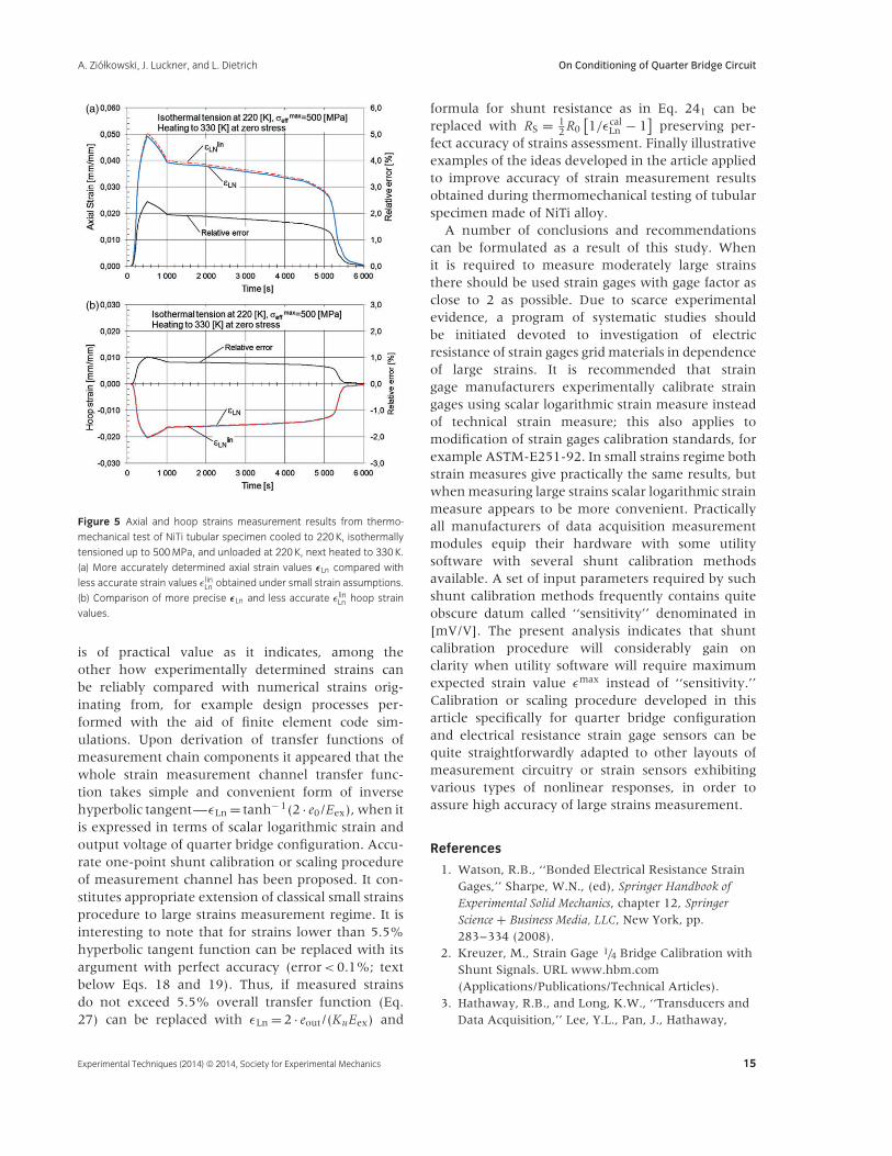
fact values of logarithmic strain (εLn), with perfect
accuracy for strains not exceeding 5.5%. In Fig. 5, for
illustrative purposes, axial and hoop strain measure-
ment results obtained in a test of isothermal tension
at 220 [K] up to 500 [MPa], unloading, and next
heating the specimen to 330 [K] are shown. Less
accurately processed due to assumptions of linear-
ity logarithmic strain values are marked εlinLn , while
more accurately processed—taking into account
nonlinearities—strain values are marked εLn. The rel-
ative error between less accurate measurement results
εlinLn and more precise strain measurement result εLn
is defined as follows: Oε (x) = | (εLn − εlinLn
)/εlin
Ln | (it is
shown in the charts of Fig. 5). Upon power series
expansion of logarithmic strain in terms of corre-
sponding technical strain—Eq. 74 and text below, it
is easy to show that Oε (x) ∼= 12εlin
Ln [%].
Concluding Remarks
Development of new production technologies andcapabilities of resistance strain gages resulted in exten-sion of their measurement range to moderately largestrains. Nevertheless, moderately large strains mea-surement with electrical resistance strain gages andconditioning of measurement channel seems to beinsufficiently examined in the existing literature. Thiscalls for detailed investigation of strain measurementchain and calibration or scaling procedure of straingage measurement module taking into account non-linearities of measurement chain components. In thiswork quarter bridge configuration has been analyzed.First, strain measurement chain, and its essentialcomponents, has been explicitly revealed. Work con-jugate family of tensorial strain measures, their scalarcounterparts, and elements of invariance of phys-ical processes description relevant in strain gagetest methodology has been discussed. The material
14 Experimental Techniques (2014) © 2014, Society for Experimental Mechanics
A. Ziołkowski, J. Luckner, and L. Dietrich On Conditioning of Quarter Bridge Circuit
(a)
(b)
Figure 5 Axial and hoop strains measurement results from thermo-
mechanical test of NiTi tubular specimen cooled to 220 K, isothermally
tensioned up to 500 MPa, and unloaded at 220 K, next heated to 330 K.
(a) More accurately determined axial strain values εLn compared with
less accurate strain values ε linLn obtained under small strain assumptions.
(b) Comparison of more precise εLn and less accurate ε linLn hoop strain
values.
is of practical value as it indicates, among theother how experimentally determined strains canbe reliably compared with numerical strains orig-inating from, for example design processes per-formed with the aid of finite element code sim-ulations. Upon derivation of transfer functions ofmeasurement chain components it appeared that thewhole strain measurement channel transfer func-tion takes simple and convenient form of inversehyperbolic tangent—εLn = tanh− 1(2 · e0/Eex), when itis expressed in terms of scalar logarithmic strain andoutput voltage of quarter bridge configuration. Accu-rate one-point shunt calibration or scaling procedureof measurement channel has been proposed. It con-stitutes appropriate extension of classical small strainsprocedure to large strains measurement regime. It isinteresting to note that for strains lower than 5.5%hyperbolic tangent function can be replaced with itsargument with perfect accuracy (error < 0.1%; textbelow Eqs. 18 and 19). Thus, if measured strainsdo not exceed 5.5% overall transfer function (Eq.27) can be replaced with εLn = 2 · eout/(KuEex) and
formula for shunt resistance as in Eq. 241 can bereplaced with RS = 1
2 R0[1/εcal
Ln − 1]
preserving per-fect accuracy of strains assessment. Finally illustrativeexamples of the ideas developed in the article appliedto improve accuracy of strain measurement resultsobtained during thermomechanical testing of tubularspecimen made of NiTi alloy.
A number of conclusions and recommendationscan be formulated as a result of this study. Whenit is required to measure moderately large strainsthere should be used strain gages with gage factor asclose to 2 as possible. Due to scarce experimentalevidence, a program of systematic studies shouldbe initiated devoted to investigation of electricresistance of strain gages grid materials in dependenceof large strains. It is recommended that straingage manufacturers experimentally calibrate straingages using scalar logarithmic strain measure insteadof technical strain measure; this also applies tomodification of strain gages calibration standards, forexample ASTM-E251-92. In small strains regime bothstrain measures give practically the same results, butwhen measuring large strains scalar logarithmic strainmeasure appears to be more convenient. Practicallyall manufacturers of data acquisition measurementmodules equip their hardware with some utilitysoftware with several shunt calibration methodsavailable. A set of input parameters required by suchshunt calibration methods frequently contains quiteobscure datum called ‘‘sensitivity’’ denominated in[mV/V]. The present analysis indicates that shuntcalibration procedure will considerably gain onclarity when utility software will require maximumexpected strain value εmax instead of ‘‘sensitivity.’’Calibration or scaling procedure developed in thisarticle specifically for quarter bridge configurationand electrical resistance strain gage sensors can bequite straightforwardly adapted to other layouts ofmeasurement circuitry or strain sensors exhibitingvarious types of nonlinear responses, in order toassure high accuracy of large strains measurement.
References
1. Watson, R.B., ‘‘Bonded Electrical Resistance StrainGages,’’ Sharpe, W.N., (ed), Springer Handbook ofExperimental Solid Mechanics, chapter 12, SpringerScience + Business Media, LLC, New York, pp.283–334 (2008).
2. Kreuzer, M., Strain Gage 1/4 Bridge Calibration withShunt Signals. URL www.hbm.com(Applications/Publications/Technical Articles).
3. Hathaway, R.B., and Long, K.W., ‘‘Transducers andData Acquisition,’’ Lee, Y.L., Pan, J., Hathaway,
Experimental Techniques (2014) © 2014, Society for Experimental Mechanics 15
On Conditioning of Quarter Bridge Circuit A. Ziołkowski, J. Luckner, and L. Dietrich
R.B., and Barkey, M.E., (eds), Fatigue Testing andAnalysis, Theory and Practice, Elsevier, Amsterdam, theNetherlands, pp. 1–56 (2005).
4. ASTM-E251-92, Standard Test Methods forPerformance Characteristics of Metallic BondedResistance Strain Gages, 2003.
5. Errors Due to Wheatstone Bridge Nonlinearity, TechnicalNote TN-507-1 Micro-Measurements, Document No11057, 19 November 2010, URLwww.micro-measurements.com.
6. Raniecki, B., Nguyen, H.V., and Ziołkowski, A., ‘‘Onthe Incremental Plastic Work and Related Aspects ofInvariance—Part 2,’’ Acta Mechanica: 79–109 (2008).
7. Nguyen, H.V., Raniecki, B., and Ziołkowski, A., ‘‘Onthe Incremental Plastic Work and Related Aspects ofInvariance—Part 1,’’ Acta Mechanica 189: 1–22(2007).
8. Ziolkowski, A., ‘‘Simple Shear Test in Identificationof Constitutive Behaviour of Materials Submitted toLarge Deformations—Hyperelastic Materials Case,’’Engineering Transactions 54: 251–269 (2006).
9. Data Acquisition Handbook, A Reference For DAQand Analog & Digital Signal Conditioning 3rd
Edition, chapter 7, Measurement ComputingCorporation, 2004–2012, pp. 81–88.
10. Kreuzer, M., Wheatstone Bridge Circuits ShowAlmost No Nonlinearity and Sensitivity Errors WhenUsed for Single Strain Gage Measurements, 2004.URL www.hbm.com (Applications/Publications/Technical Articles).
11. Hill, R., ‘‘Aspects of invariance in solid mechanics’’,Adv. Appl. Mech. 18: 1–75 (1978).
Notations
XY: XY − XijY j or XijY jk or XijklY kl
X · Y: XiY i or XijY ij, tr(XY) = XijY ji
X ⊗ Y: XiY j
XT: Transpose of X(
XTij = Xji
)X− 1: Inverse of X
(X−1
ij Xjk = δik
)1: Unit tensor (δij)
16 Experimental Techniques (2014) © 2014, Society for Experimental Mechanics