on-board decision support through the integration of ... · mlu mid life update ... part i: a crew...
TRANSCRIPT

NLR-TP-2001-611
On-Board Decision Support through theOn-Board Decision Support through theOn-Board Decision Support through theOn-Board Decision Support through theIntegration of Advanced InformationIntegration of Advanced InformationIntegration of Advanced InformationIntegration of Advanced InformationProcessing and Human Factors TechniquesProcessing and Human Factors TechniquesProcessing and Human Factors TechniquesProcessing and Human Factors TechniquesThe POWER Project
H.H. Hesselink, G.D.R. Zon, F. Tempelman, J.W. Beetstra,
A.M. Vollebregt, D.P. Hannessen

NationaalNationaalNationaalNationaal Lucht- en Ruimtevaartlaboratorium Lucht- en Ruimtevaartlaboratorium Lucht- en Ruimtevaartlaboratorium Lucht- en RuimtevaartlaboratoriumNational Aerospace Laboratory NLR
NLR-TP-2001-611
On-Board Decision Support through theOn-Board Decision Support through theOn-Board Decision Support through theOn-Board Decision Support through theIntegration of Advanced InformationIntegration of Advanced InformationIntegration of Advanced InformationIntegration of Advanced InformationProcessing and Human Factors TechniquesProcessing and Human Factors TechniquesProcessing and Human Factors TechniquesProcessing and Human Factors TechniquesThe POWER Project
H.H. Hesselink, G.D.R. Zon, F. Tempelman, J.W. Beetstra,
A.M. Vollebregt, D.P. Hannessen
This investigation has been carried out under a contract awarded by Netherlands Ministryof Defence, contract number DGM/DWOO/N98-38.Netherlands Ministry of Defence has granted NLR permission to publish this report.
This report is based on a presentation held at the NATO SCI lecture series on "TacticalDecision Aids and Situational Awareness" in Amsterdam (1-2 November 2001), Sofia(8-9 November 2001), Madrid (12-13 November 2001) and Patuxent River (MD)(19-20 November 2001) and at the NVvL (Nederlandse Vereniging voor Luchtvaart-techniek, Amsterdam, 29 November 2001.
The contents of this report may be cited on condition that full credit is given to NLR andthe authors.
Division: Information and Communication TechnologyIssued: December 2001Classification of title: Unclassified

-3-NLR-TP-2001-611
Summary
As advanced crew support technologies will be available more and more in future militaryaircraft, it is necessary to have a good understanding of the possibilities in this area, taking intoaccount operational demands, technical possibilities, human factors, evaluation, and validationaspects. A Crew Assistant (CA) is a decision support system for air crew, designed to improvemission effectiveness and redistribute crew workload in such a way that the crew canconcentrate on its prime tasks.
The POWER (Pilot Oriented Workload Evaluation and Redistribution) project is a NetherlandsNational Technology Project. The project is aimed at demonstrating a generic CA environmentand individual tactical decision support tools to military pilots in a simulated environment, theNSF (National Simulation Facility), a six-degrees of freedom cockpit in a visual dome.
The project is a technology demonstration project to show new CA features. An advancedsoftware architecture has been set up, based on multi-agent technology, where software "agents"co-operate in sharing information and using resources on an as-needed basis. Each agent is anautonomous piece of software that is able to anticipate courses of action and performs itsfunction pro-actively.
Several prototypes of crew assistant agents have been developed and integrated in order tofacilitate a CA demonstrator and a large-scale experiment with operational pilots from the RoyalNetherlands Air Force (RNLAF) has been carried out to demonstrate the effects of CAtechnology as decision support, to validate tools, and to measure the effects of on-boarddecision support in enhancing pilot situational awareness.
The prototypes and experiments have proven the benefits of demonstrating the technology topilots; after initial scepticism, they felt confident with using the tools after a while without beingafraid to loose their skills for manual actions. The experiments also proved the benefits of CrewAssistant tools with respect to mission effectiveness and tactical task accomplishment in highlycomplicated situations. From a technical perspective, the possibility for real-time and any-timeon-board reasoning was proven.
This paper describes the demonstration CA environment and provides insight into the differentCA components. Part one describes the environment as a generic CA architecture that can beinstalled on a simple work station as well as in a full-scale simulation environment. The secondpart of this paper describes the aforementioned experiment, where the NLR Counter MeasureManager (NCMM) and the contents of the experiment will be detailed.

-4-NLR-TP-2001-611
Abbreviations
AI Artificial IntelligenceAIP Advanced Information ProcessingCA Crew AssistantCAMA Crew Assistant Military AircraftCASSY Cockpit Assistant SystemCTM Counter Measure TechniqueCOGPIT Cognitive CockpitDERA Defence Evaluation Research AgencyDoD Department of DefenceECG ElectrocardiogramECOP Electronic Co-pilotEPOG Eye Point Of GazeEUCLID European Co-operation for the Long Term in DefenceEW Electronic WarfareHF Human FactorsHMI Human Machine InterfaceHR Hart RateHRV Hart Rate VarianceMAW Missile Approach WarningMFD Multi Function DisplayMLU Mid Life UpdateMLW Missile Launch WarningMSDF Multi-Sensor Data FusionNADDES NLR Avionics Display Development and Evaluation SystemNCMM NLR Counter Measure ManagerNLR National Aerospace Laboratory
(Nationaal Lucht- en Ruimtevaartlaboratorium)NSF National Simulation FacilityPA Pilot's AssociatePOWER Pilot Oriented Workload Evaluation and RedistributionRCM Reflex Counter MeasureRGPO Range Gate Pull OffRNLAF Royal Netherlands Air ForceRPA Rotorcraft Pilot's AssociateRWR Radar Warning ReceiverSAM Surface to Air Missile
-5-NLR-TP-2001-611
Contents
PART I: A CREW ASSISTANT ARCHITECTURE 6
1 Introduction 6
2 Crew Assistant Technology 7
3 The Architecture 103.1 A Functional Architecture based on Multi-Agent Technology 113.2 Reasoning with Uncertainty for Profile Recognition 143.3 Manoeuvre Prediction with Case Based Reasoning 153.4 NLR’s Counter Measure Manager (NCMM) 163.5 Display Development with NADDES 17
PART II: A THREAT MANAGEMENT DECISION SUPPORT EXPERIMENT 18
4 NLR Counter Measure Manager (NCMM) 19
5 A threat management support experiment 225.1 Experiment Description 225.2 Experiment design 245.3 Measurements and equipment 245.4 Results 25
6 Conclusions from the POWER project 27
7 References 28
(30 pages in total)

-6-NLR-TP-2001-611
PART I: A CREW ASSISTANT ARCHITECTURE
1 Introduction
Software and human factors are becoming major part of current and future on-board avionics.Current developments in software engineering and advanced information processing techniquesenable complex crew assistant applications, especially support of the aircraft crew in carryingout primary and secondary tasks is more and more provided by electronic systems. Applicationof crew assistants in fighter aircraft is a challenging task, both for the research and developmentof the software, as for the human factors aspects concerning its optimal use and trust of the pilotin the system.
The POWER (Pilot Oriented Workload Evaluation and Redistribution) project, is a NetherlandsNational Technology Project. The project is aimed at demonstrating a generic Crew Assistant(CA) environment and individual tactical decision support tools to pilots in a simulatedenvironment, the NSF (National Simulation Facility), a six-degrees of freedom F-16 cockpit in avisual dome. This demonstrator has been the focus of the project.
Current progress in advanced information processing, new advances in human factors, and thepossibility to validate new avionics so that pilots learn to trust the system, form the basis for thispaper in order to support RNLAF in the acquisition and usage of new aircraft. In this paper, ageneric simulation environment is discussed, that enables different levels of crew assistantdemonstration and experimentation. The environment proposed is based on multi-agenttechnology, where a generic Crew Assistant environment can be plugged onto a "simple"scenario generator on a work station or to a full-scale flight simulation facility, like the NSF.
Several prototypes of CA agents have been developed and integrated in order to facilitate theCA demonstrator:• A profile recognition agent takes input from different sensors and recognises profiles in a
data fusion assembled picture. The agent reasons with uncertainty in the observation anduses Bayesian Belief Networks to model the profile and sensor's characteristics.
• A manoeuvre prediction agent assesses an opponent's manoeuvre and predicts the pattersthat will be flown when in air-to-air combat. This tool is based on case-based reasoningtechnology.
-7-NLR-TP-2001-611
• The NCMM (NLR counter Measure Manager) agent advises counter measures againstthreats, e.g. SAM-sites. The tool is based on expert system technology.
• An HMI is designed with an NLR built tool, NADDES (NLR Avionics DisplayDevelopment and Evaluation System), for increasing pilot situation awareness.
This paper will provide an overview of the POWER project. It has been set up in two parts,where the first part describes the generic CA architecture and part two describes a large scaleexperiment that has been carried out. Chapter two will introduce crew assistant technology andchapter three will describe the software architecture, which is based on multi-agent technology.Chapter four describes the technical aspects of the simulation environment the experiment.Chapter five describes the setting and results of this experiment.
2 Crew Assistant Technology
Fighter pilot's workload is rapidly increasing. Modern military operations take place in acomplex environment to accomplish a spectrum of missions. The most important factor in theincrease in workload concerns the operational environment of current fighter aircraft:• The increase of the complexity of the military environment in general (e.g. combined joint
task forces, peace keeping/peace enforcement).• The increase of the complexity of the types of missions to be flown.• The increase in the number of different (kinds of) threats.
Another factor is the technological developments of fighter aircraft. The increase in aircraftspeed and aircraft types and on-board systems causes the aircraft itself to become much moredifficult to manage, putting more pressure on the crew. During high-stress situations, the crewcan get overloaded with information, while it has to perform a multitude of actions. Figure 1illustrates the possible information overload and decision making process.
A Crew Assistant is an on-board decision support system that supports the crew in performingits mission. It aims at improving mission effectiveness, flight safety, and/or survivability byproviding the crew with concise and relevant information, depending on the mission phase, thusenabling the crew to concentrate on mission decisions and make more effective decisions.[Urlings 1995]. In essence, Crew Assistants change the nature of the information that sensorsprovide to enable decision making, hence "information" is transferred to "knowledge". CrewAssistants are decision support systems for air crew, designed to improve mission effectivenessand redistribute crew workload in such a way that the crew can concentrate on its prime tasks.Ideally, a CA assists a pilot, or other crew members, by providing the following kind offunctions:

-8-NLR-TP-2001-611
• Acquire the necessary information and merge the input from different sensor andinformation systems into one timely and consistent view of the current situation (the statusof different on-board systems, the situation outside, etc.).
• Process the merged information to give advice (weapons selection, route planning, tacticsevaluation, fuel management, etc.).
• Perform tasks autonomously when so instructed by the pilot or another crew member(autopilot, target tracking, systems monitoring, etc.).
Figure 1. The information requirements of the crew [Yannone, 1985].
As advanced crew support technologies will be available more and more in future (military)aircraft, it is necessary to have a good understanding of the possibilities in this area, taking intoaccount operational demands, technical possibilities, human factors, evaluation, and validationaspects.
The current state-of-the-art in advanced information processing now makes intelligent pilotassistant through a CA technically feasible, including real-time on-board data acquisition,fusion, and processing. Advanced information processing techniques, like expert systems andneural networks, and methods for constraint reasoning, case based reasoning and reasoning withuncertain and incomplete information, can be used in the military cockpit. Research in HumanFactors technology aspects, will make the techniques available to the human operator. For an

-9-NLR-TP-2001-611
overview of systems and technologies, see e.g. [Boers 1999], [Van Gerwen 2000-1],[Verhoeven 2000].
In the course of the years, several CA programs have been set up. The Crew Assistant MilitaryAircraft (CAMA) is a German DoD programme that investigates the use of an intelligentelectronic crew member in the military transport application [Strohal 1997], [Frey 1999].Within the programme, flight simulator trials have been performed in the simulator of theUniversity of the German Armed Forces. Flight experiments are scheduled in an in-flightsimulator. Hands-on experience and feed back from pilots is a factor in the development ofsystems that must be gained. One project that takes a human factors perspective on CAs is theCognitive Cockpit (COGPIT) project, that has been set up by the UK Ministry of Defence inconjunction with the Defence Evaluation Research Agency (DERA). This project seeks todevelop a theoretically grounded, human-centred approach for guiding a principleddevelopment of intelligent pilot aiding concepts for cockpit automation [Taylor 1998],[Taylor 2000]. It researches the cognitive engineering aspects of the pilots to couple knowledge-based systems for situation assessment and decision support with concepts and technologies foradaptive automation and cockpit adaptive interfaces. Other CA projects are Pilot's Associate(PA) [Holmes 1991], Rotorcraft Pilot's Associate (RPA) [Collucci 1995], CoPiloteElectronique, Cockpit Assistant System (CASSY) [Onken 1997], and the Electronic Co-pilot(ECOP) [Stein 1987].
These programs take either a technological or a human centred focus on CAs. We believe thatfor a good integration of CA technology in the cockpit, the relationship between the fields ofAdvanced Information Processing (AIP) and Human Factors (HF) should be exploited further.The POWER project brings together the fields of military operations research, advancedinformation processing and human factors. It combines techniques from artificial intelligenceand human machine interaction in such a way that pilots are supported with advanced crewassistants, wherewith the information is provided to them in a sense that a fused picture of theworld emerges. Apart from the technological aspects, the POWER project has strong roots inthe analysis of requirements and needs from operational fighter pilots. The project will helpdecision makers in technology assessments for acquiring new aircraft and equipment andmanufacturers in making strategic decisions on technological programmes.
In many cases, information will be time dependent, inaccurate and incomplete. The use ofuncertain and incomplete information should be further investigated and must be considered inthe design of the Human Machine Interface (HMI). The project therefore, focuses on thefollowing challenges:

-10-NLR-TP-2001-611
• Provide a flexible demonstration environment for crew assistant technology, based onoperational demands from fighter pilots.
• Provide examples of crew assistant technology, based on new advanced AIP and HFaspects.
• Provide insight in new real-time reasoning techniques for reasoning with uncertainty.• Provide a quantitative scientific base that proves the benefit and user acceptance of CA
technology.• Perform experiments with the demonstration environment that lays a basis for further work
in the field of introducing CA technology to the RNLAF.
3 The Architecture
Until recently, work in on-board automation focussed on the introduction of single self-supporting functions. The advantage of this is high reliability in case of single failures, whereother independent systems take over. Instead of relying on the information that one sensorprovides, CA decision support functions in essence focus on the integration of information andthe provision of a complex and fused picture to the pilot. This creates new demands for thesoftware and hardware architecture and the human factors aspects.
Decision support functions are concerned with data acquisition, fusion, and processing and useinformation from different sources, so that an architecture is needed, where the system does notrely on one information source and does not contain any critical processing nodes. We believethat an architecture based on agent technology can and will play an important role in the nearfuture in avionics. Agent-based architectures have been introduced for on-board decisionsupport systems in e.g. TANDEM [Barrouil 1999], the Cognitive Cockpit [Taylor 2000], andfor on board multi-sensor data fusion [Bossé 1999].
The strength of software agents is that they can be made to interact with other software agentsor human users. Agents are “small” autonomous black boxes, which handle their own clearlydefined tasks. A system of agents that co-operates is called a multi-agent system. Agents, ifwell-designed as separate processing units, enable communication between multiplesubsystems, without putting a strain on one specific part of the system. Their loose couplingprovides a possibility to introduce new technology throughout the aircraft's lifetime, especiallyat "end of the line" functions, like weapon systems, where it is relatively easy to validate newtechnology.
This chapter will give an overview of the proposed multi-agent architecture and will describethe most important CA components that have been provided with the POWER project.

-11-NLR-TP-2001-611
3.1 A Functional Architecture based on Multi-Agent TechnologyThe proposed architecture has been based on the results of earlier projects, like the EUCLID(European Co-operation for the Long Term in Defence) Research and Technology project 6.5[Zuidgeest 1995]. This NLR-led project on CAs for military aircraft started with extensive userinterviews to establish an inventory of operational user problems and needs for pilots flyingF-16, Tornado, and AM-X. The project came up with a generic on-board CA architecture andindicated a challenge in the application of multi-agent systems and knowledge based systems.
The architecture that has been set up for the POWER project distinguishes four groups offunctional agents. The groups are (1) data and information input agents, like sensors and themulti-sensor data fusion agent, (2) data processing agents which form the actual crew assistantfunctions, (3) information output agents mainly to the pilot, and finally, (4) the weapon agents.Apart from these, other agents perform functions for controlling and monitoring the overallsystem's status and health. In this paper, we will focus on the functional part of crew assistants,see figure 2.
The four functional groups further subdivided in seven subgroups (see slight colour differencesin figure 2), discussed below.
Figure 2. Functional architecture of on-board agents

-12-NLR-TP-2001-611
Internal sensor agents are system components that transform the raw input data from the sensorhardware to an understandable format for the Multi-Sensor Data Fusion (MSDF) component. Inour example, we included sensors to detect and distinguish SAMs and to detect incomingmissiles.• A Radar Warning Receiver (RWR) provides the position of ground threats, including an
indication whether the SAM is in search, track, or guidance.• The Missile Launch Warning (MLW) is a passive infrared plume detector that provides
missile information while its motor is burning.• The Missile Approach Warning (MAW) is an active short range radar that detects a missile
body, usually in a two to three miles range.
External sensor agents are components that obtain their information from sensors orinformation systems that are physically located outside the aircraft, for example an AWACS ora Link-16. These sensor agents transform data and information into an understandable formatfor the MSDF agent or for the CA agents.
The Multi-Sensor Data Fusion agent combines the sensor information from all internal andexternal sensors into a combined sensor data picture. This agent may perform complex situationassessment tasks. In the current implementation, this is a fusion process that only provides theinformation to the CA's that is really necessary for the CAs to perform their task. Differentprojects have already shown the complexity of a multi-sensor data fusion process and haveproposed architectures [TA-10], [Bossé 1999]. The latter proposes an agent based architecturefor multi-sensor data fusion, which shows the flexibility of agent systems, where agents candelegate tasks to (sub-)agents.
Crew Assistant agents are the intelligent pilot support functions. The ones mentioned in figure 2are elaborated in the POWER project (based on [Zuidgeest 1995]), however, the range of pilotsupport functions is not limited to these. CAs can be further classified into functions asinformation finding in the fused sensor picture (like profile recognition, see section 3.2), pilotadvice (like manoeuvre prediction, see section 3.3, and NLR's Counter Measure Manager, seesection 3.4 and chapter 4), pilot monitoring, mission monitoring, etc. Other classifications arepossible, like [Barrouil 1999], [Taylor 2000].
Weapon agents control the weapon delivery. In this example, a number of softkill weapons tocountermeasure ground threats is displayed. Their intelligence for example consists of providingthe correct jamming against a recognized threat or dispensing a complex pattern of chaff andflare.

-13-NLR-TP-2001-611
The Display agent is responsible for assembling an integrated picture of crew assistantinformation and for prioritizing information provision to the pilot. If necessary, it can holdinformation that is considered less important at a certain moment or less time critical, if the pilotis assumed to get overloaded with information. Once the situation is more relaxed, it can decideto provide this information. An even more intelligent display agent can decide what informationshould be provided on which cockpit display, or what information should be provided on whichpart of the cockpit display and automatically adapt the contents of the available displays if at (acertain part of) one of the displays an information overload is eminent. This technology,however, should be introduced with care [Verhoeven 2000].
The Human Machine Interface agent is the actual cockpit display that provides the informationon the user interface. It may take inputs from the user.
For a generic CA demonstration environment, we require a crew assistant independently fromits operational environment. Obviously, a generic demonstration environment, especially acomplex one as a crew assistant requires a number of general tools, like scenario generationtools and environment databases. The currently developed environment connects the tools toITEMS, which provides a topographical scenario and an F-16 aircraft model. This enables thepossibility to connect the crew assistant to e.g. a fly box, see figure 3, to the NLR's F-16 mockup simulator, and to the NSF, see figure 4.
Figure 3. Flybox and workstation configuration Figure 4. National Simulation Facility

-14-NLR-TP-2001-611
3.2 Reasoning with Uncertainty for Profile RecognitionReasoning with uncertainty will be an important aspect of CA technology. Even the informationfrom a fused sensor picture will usually contain unclear elements. To investigate possibilities ofreal-time reasoning with uncertainty, a profile recognition agent was developed.
Any crew assistant will gather information from its environment, process this information, andact upon it. Probabilistic methods for reasoning with uncertainty have gained a lot of interest inthe last few decades. The introduction of Bayesian Belief Networks [Pearl 1988], [Jensen 1996]made practical application of probabilistic reasoning possible. Most applications have beentargeted at decision support in the medical domain where the variables in the model typicallyhave a few states and no real-time constraints exist. In contrast, the decision support systems forfighter pilots have to deal with many real-valued sensor readings that provide measurementsevery split second and that need to be processed in real-time [Van Gerwen 2000-2].
Suppose an aircraft has on-board sensors to identify profiles. In this example, different profilesare considered and the aircraft sensors can measure length, width, and speed of the objects thatare sensed. However, sensor accuracy depends on weather conditions, in particular visibility,cloud coverage, and humidity. This scenario is modelled through a Bayesian Belief Network asgiven in figure 5. Each of the profiles modelled, has an a-prior probability distribution.
Length Width Speed
LengthMeasure WidthMeasure
Object
Radar
CloudCoverageVisibility
WeatherType
Humidity
Figure 5. Bayesian Belief Networks for profile recognition

-15-NLR-TP-2001-611
The goal of this research is to look into the possibility of creating an anytime algorithm for aBayesian Belief Network. Anytime algorithms are algorithms that trade performance for time.As the amount of time is increased, an anytime algorithm improves the quality of the output.One of the features of anytime algorithms is that it can provide intermediate results at anymoment, so that the available processing power and time can be regulated.
Propagating evidence in a Bayesian belief network can be a very time-consuming task (it is NP-hard). One solution might be an algorithm that uses state-space abstraction. We examineddifferent AI techniques, like Breadth First, Breadth First Split, and Highest Belief First. Figure 6gives the results of the different methods.
In the CA agent, we have shown that state-space abstraction in combination with a strategy suchas Highest Belief First has interesting features required for an anytime algorithm. The proposedmethod outperforms simpler methods like Breadth First and Breadth First Split.
time (ms)
Figure 6. Running the BBN with different techniques to facilitate state space abstraction
3.3 Manoeuvre Prediction with Case Based ReasoningThe proposed Manoeuvre Prediction agent seeks to enhance the situation awareness of the pilotin a dogfight situation. Given information on the opponent’s aircraft, like position and speed,the agent will try to determine the manoeuvre it is performing. Using this information, the agentcan predict the future path of the opponent’s aircraft. This information is then presented to the

-16-NLR-TP-2001-611
pilot, thus enhancing situational awareness. Benefits for this tool can be found in the earlierphases of a dogfight, where the opponent just enters visual range and the pilot is making anassessment of his radar and visual clues to determine the most beneficial counter actions.
The rapid changing environment in which such an application has to operate called for a strictreal-time or any-time approach for the Manoeuvre Prediction agent. We also wanted to exploitthe fact that every encountered dogfight involves manoeuvres that the application could use forfuture manoeuvre prediction.
It was decided, to use the case based reasoning technique from the field of artificial intelligencefor implementing the Manoeuvre Prediction agent. The case bases reasoning technique willstore cases (one manoeuvre is one case) in a database and provide means by which a newlyencountered case can be compared to existing cases. The most similar case (manoeuvre) can beretrieved and used as source to indicated the encountered case. The newly encountered case willbecome part of the database for future use. This way of working is highly intuitive for humans,we learn from experience and try to recognise by comparing the current situation to pastexperiences.
The scientific challenge for implementing the Manoeuvre Prediction was to make the case basedreasoning process work in real-time. We solved this by ordering the cases by individualelements of the manoeuvre (e.g. speed or distance from own-ship). Having an order in thedatabase gives fast information where to look for the most similar case. In the end the searchalgorithm will quickly find the most similar case, but more importantly the algorithm will alsoperform well in anytime and will produce a fairly similar case, once interrupted.
Using the advanced software architecture of multi-agent technology the results from theManoeuvre Prediction application are made available to the other applications (agents). Theseagents can use this information for their own purposes. The HMI agent will graphically displaythe information for the situational awareness of the pilot. The NCMM agent may use thisinformation to take counter measures based on the enemy’s aircraft predicted position. Theinformation may be sent to agents of nearby ground or airborne forces for their tactical decisionaid or situational awareness.
3.4 NLR’s Counter Measure Manager (NCMM)The NCMM agent determines the most effective use of actors to counter detected threats. Suchan agent enables co-ordinated counter measures that can not be performed manually using theseparate systems. Most notably, this involves counter measures combining jamming and chaff.

-17-NLR-TP-2001-611
Furthermore, the manager can enhance effectiveness by combining counter measures to countermore than one threat simultaneously [Tempelman 1999], [Eertink 2000].
More information on the NCMM can be found in the second part of this paper, which describesan experiment to study the effects of decision support in the military cockpit and that has beencarried out with the NCMM.
3.5 Display Development with NADDESAn HMI (Human Machine Interface) is designed with an NLR built tool, NADDES (NLRAvionics Display Development and Evaluation System) for increasing pilot situation awareness.NADDES is a development environment that has specifically been developed for theconstruction of avionics displays and as such, it provides a number of predefined components.
For the aforementioned demonstrations, separate HMIs have been developed. Since alldemonstrations use the same development environment, they can easily be integrated to formone situation awareness picture for the pilot. The display manager agent decides whichinformation to display on the available on-board HMIs.
An example of a NADDES developed HMI for the NCMM is given in figure 7.
1
22
2
3
41
SA 3 SA 3
Figure 7 NCMM display

-18-NLR-TP-2001-611
PART II: A THREAT MANAGEMENT DECISIONSUPPORT EXPERIMENT
The second part of this paper describes a Crew Assistant and Situation Awareness experimentthat has been carried out involving operational RNLAF pilots in the NSF simulator at NLR,Amsterdam. We will first give an elaborated overview of the NCMM tool that has been usedand then focus on the details of the experiment.
The current military theatre becomes ever more complex and demanding for the pilot. Thisdevelopment is potentially threatening to the situational awareness of pilots and as such, to theirsafety. Solutions to keep track of the situation are sought, amongst others, in automated tacticaldecision aids. To what extend will pilots benefit from such systems? Will mission performanceincrease? What are the disadvantages? To answer these questions an experiment was designed,which will be described in this part of the paper. The experiment can be characterised best as anevaluation by fighter pilots of a threat management support system.
Figure 8. F-16 MLU cockpit
The experiment is performed in the NLR National Simulation Facility (NSF), see figures 4and 8. This simulator is configured with an F-16 MLU cockpit. Mission profiles and controlsused by the pilots during the experimental runs were recorded. Instrumentation and fittingsallowed variables such as heartbeat frequency, eye point-of-gaze, pupil size, and eye blink rateto be measured.
Pilots flew through scenarios in which they encountered several threats. The task load betweenthe scenarios was varied by the amount of surface threats that were implemented in thescenarios. In half of the test runs pilots had to deal with the treats manually, while in the otherhalf an automated system initiated appropriate counter measures by itself.

-19-NLR-TP-2001-611
Afterwards pilot performance, subjective and objective mental workload and the pilotappreciation of the automated threat management system were evaluated. For the experiment,we used the NCMM, mentioned in section 3.4 and further extensively described in chapter 4.Chapter 5 will present the experiment set up and describe the results.
4 NLR Counter Measure Manager (NCMM)
To countermeasure SAMs, the pilot has several options available. Generally, the best course ofaction is to avoid entering SAM rings, but this cannot always be avoided, especially when pop-up threats are encountered. Depending on the type of threat and its state, the pilot can jam ordispense chaff en flares. Usually, these counter measures are combined with a manoeuvre.
The NCMM agent determines the most effective use of actors to counter detected threats. Suchan agent enables co-ordinated counter measures that can not be performed manually using theseparate systems [Tempelman 1999], [Eertink 2000]. A schematic representation of themanager’s architecture is supplied in figure 9.
MSDFHMI
MSDF-RM
ITEMS
ITEMS-RMRCM Activator CMT Scheduler System
RCM KB CMT KB
RESOURCE MANAGER
Figure 9. The NCMM in the simulation environment.
The MSDF agent delivers environment data, most notably sensor tracks and threat information,to the resource manager. The resource manager is the core of the NCMM. It consists of tworule-based knowledge bases: the Reflex Counter Measure (RCM) Knowledge Base and theCounter Measure Technique (CMT) Knowledge Base. The first associates sensor tracks directlyto single counter measures (e.g., chaff, flare, a jamming technique, a manoeuvre), in situationswhere immediate action is required. The latter connects threats, i.e., fused sensor tracks, under

-20-NLR-TP-2001-611
certain positional conditions to a series of counter measures, after which the dynamicallyplanning CMT Scheduler fits these into the existing counter measure schedule.
An example of the represented CMT knowledge is given in table 1. Rule number 12(highlighted in the table), for example, represents what can be done to counter a threat of typeSAM1 in track (T) mode, which has threat level (lethality) 4 on a scale of 0 to 10. The SAM1 isdetected by two sensors, the Radar Warning Receiver (R) and the ALQ (J). With an expectedeffectiveness of 8 on a similar scale, it can be countered by a combination of Range-Gate Pull-Off (a jamming technique) followed by dispensing 4 bundles of chaff with an interval of 0.2seconds (4C0.2), if the condition on the threat’s position is fulfilled.
The knowledge in the resource manager is highly flexible. It can be adapted easily to includenewly constructed counter measure techniques and it can be modified to reflect the availabilityof other agents in the aircraft in which the NCMM is running.
Various operational modes are available in the NCMM. These determine the availability ofassets in various circumstances. For example, it can be necessary to not use jamming countermeasures, as the enemy can detect these. Selecting the operational mode ‘Run Silent’ will thentake care of this. Furthermore, the NCMM agent supports system modes, determining theamount of automation of the system. These vary from manual, in which case only advises aregiven, to fully automatic, in which case all counter measures except manoeuvres are executedautomatically and in time. For reasons of pilot convenience, manoeuvres will only be advised.
The NCMM was evaluated and validated in a semi-realistic simulation environment calledITEMS. Various scenarios were flown in various modes. A simple scenario, in which no threatsoverlap, is shown in figure 10. The flexibility of the manager was demonstrated by running itboth in a simulated F-16 and in an Orion P3, the latter having far less counter measurepossibilities. The NCMM demonstrated improved effectiveness and efficiency of usingcountermeasures against threats in a number of multi-threat scenarios, compared to manuallythreat countering. Advantages are that series of counter measures that require exact timing withrespect to each other can be executed automatically, that the NCMM can combine countermeasures to counter multiple threats, and that the NCMM can take the effect of a countermeasure against a threat to other threats into account in highly complicated situations.

-21-NLR-TP-2001-611
ID Threat Mode TL Sensors Effectiveness GCMT1 SAM1 S 3 R 5 OTCONDITION: None# Simple example: SAM1 search radar (low TL) detected by RWR only; Turn to evade the site.
2 SAM1 S 3 R+J 8 N1SCONDITION: None# As above, only now the site is also detected by the ALQ, so jamming can be used (Noise).
12 SAM1 T 4 R+J 8 RGPO1C+4C0.2CONDITION: Threat at (20°<F<60°)∨ (300°<F<340°)# Sam is tracking the aircraft. Combination of RGPO and chaff is effective, but only at certainazimuth angles
32 SAM1 L 9 R+J+MA 8 VGPO1CONDITION: Time Till Intercept≥5s# see number 34.
34 SAM1 L 10 R+J+MA 5 6GturnIntoCONDITION: Time Till Intercept<5s# Missile is launched, detected by MAW. Assuming semi-active missile, VGPO can beattempted. If this fails (TTI<5s), perform last ditch manoeuvre
Table 1. Part of the CMT knowledge base
FRIENDLY HOSTILE
SAM4
SAM4
SAM1
SAM2
AAA
IR3
IR2
IR1
SAM3
480 kts
t=8 min
t=20.5 min
t=30.5 min
t=36 min
SAM1
150 or20000 ft
180 NM70 NM
150 NM
Figure 10. Example scenario for NCMM validation.

-22-NLR-TP-2001-611
5 A threat management support experiment
This chapter describes the experiment set up and the results.
5.1 Experiment DescriptionThe purpose of the current experiment is to demonstrate the advantages and disadvantages of aCA. The experiment will show whether automation about threat management tasks is beneficialto the mission compared to the current situation, in which pilots have to perform these taskswithout such support. To define the additional value of the support, the mission performance,the subjectively and objectively measured fatigue and workload of the pilots has beeeninvestigated. NCMM served as the threat management support system (the CA).
The experiment was designed to answer the following specific questions:• Does decision support improve pilot performance (fighter performance, mission
effectiveness), especially in situations in which a great deal of the pilot’s attention is neededfor other tasks (high taskload saturation)?
• Will pilots appreciate the tool when they can be convinced that the pilot always remains incontrol?
• Will the integrated way of information presentation, that is part of the CA interface in thecurrent experiment, aid the pilots in gaining and remaining their situational awareness?
• Will pilots get a better understanding and appreciation of the tool after they are given timeto test it thoroughly?
• Will pilots either experience a workload decrease, a performance increase, or a combinationof both as a result of the CA?
• The moments with the highest workload are needed here. Heart rate during those momentsshould be compared between the CA on and the CA off.
Nine operational male F-16 pilots from the Royal Netherlands Airforce participated each forone day in the experiment. The right Multi Function Display (MFD) was reserved entirely forNCMM. Swapping the NCMM page, or removing it from the MFD, was not possible. The pilotwas informed about NCMM system mode before the run started.
During half of the runs NCMM operated in the standby mode. In this mode NCMM providesexplanatory information about the location and type of the surface threats and the flight pathonly. In this mode NCMM does provide the same information as what is now available on thecurrent F-16 MLU Multi Function Displays in combination with the Radar Warning Receiver(RWR). The pilot selected and executed the counter measures against the threats manually. He

-23-NLR-TP-2001-611
had to actively dispense chaff and flare and select the jamming mode. Manoeuvres had to beexecuted manually.
During the other half of the runs NCMM operated in the automatic mode. In this mode NCMMdecides when to expend chaff and flare and dispenses them automatically. The pilot candispense additional chaff and/or flare manually in this mode. Also the appropriate jammingmodes are selected automatically. In addition, NCMM also advises about appropriatemanoeuvring. However, the execution of the manoeuvres has to be done by the pilot.
The pilots’ task was to fly six low altitude weapon delivery missions. Each run had the samemission goals but the mission profile was different every time. Pilots were instructed to stay tothe assigned flight path as much as possible. They were also asked to fly low altitude, thoughnot too low so that they would not fly below radar coverage. The pilots were recommended touse NCMM advice if they felt that it was tactically sound, but to otherwise execute their ownplan. Each scenario consisted of a short flight (duration was about ten to fifteen minutes) inwhich the subjects encountered a number of threats. During the runs several threats could popup. Given the nature of NCMM it was decided to use, primarily, surface threats. Pre-plannedthreats and steer points were chosen such that the missions that the pilots were flying could wellbe compared. Pop-up threats always combined to a pre-planned threat in such a way that alogical course of action would follow. An example of a mission with pre-planned threats isgiven in figure 11. The dashed circles represent the threats with a numbered classification(fictive). The line is the route to be followed, including numbered way points. Way pointnumber five is the target.
1
5-Target
64
3
27
1 2
1
3
3
3
3
Figure 11. Example mission with pre-planned threats.

-24-NLR-TP-2001-611
5.2 Experiment designIn one condition NCMM provided decision support (automatic mode). This condition wascompared to a condition in which NCMM provided explanatory information about the threatsonly (standby mode) but no advice was offered.
The effect of NCMM was investigated both under high task load and low task load conditions.During half of the runs the pilot was flying in a low workload environment. A limited amount ofsurface threats was present during those runs. During the other half of the runs a high workloadenvironment was presented. In these scenarios more surface threats were present and enemyfighter aircraft could be encountered.
The benefits of NCMM were compared between the two NCMM modes and the two levels oftask load. The above means that the pilots had to fly scenarios in four different configurations.
Since pilots had to fly six runs each and because it was undesired that they transferredexperience between scenarios, three different mission profiles were developed. The runs wereassigned over these profiles and the four experimental conditions. This approach ensured thatpilots never flew the same run twice. It also ensured that they flew three runs with NCMM instandby and three in automatic mode and it finally ensured that they flew three runs in a highand three in a low workload condition.
5.3 Measurements and equipmentDuring the missions, all information that was exchanged between the agents and between theagents and the pilots was logged. Besides, psycho-physiological measurements were taken andthe pilots were asked to fill out questionnaires at several moments during the day.
In close co-operation with operational experts, simulator events have been valued in terms ofperformance. Based upon the hypotheses a selection of simulator and NCMM variables wasmade, in order to be recorded. These comprise amongst others: countermeasures made byNCMM (in automatic mode), countermeasures made by pilot (in stand by mode), missionduration, amount of time spent in search or track of threats, deviations from the flight path, andweapon delivery events.
Heart rateIn addition to the simulator logfiles, other objective indicators of mental workload, namelypsychophysiological parameters, were recorded by the Vitaport 1 system. Those comprise theelectrocardiogram (ECG) and respiration. ECG was measured with three Ag/AgCl electrodes.One was attached approximately 4 cm. above the jugular notch of the sternum, one at the apex

-25-NLR-TP-2001-611
of the heart over the ninth rib, and the ground electrode was placed above the right iliac crest.The ECG was used to determine the Heart Rate (HR) and Heart Rate Variance (HRV).Respiration was measured using a pair of strain gauge transducers around the chest and theabdomen, so that the influences of respiration rate, and speech, on HRV could be filtered outlater. During the offline data analysis HR artefact correction was carried out according to aprocedure described by [Mulder 1988].
Eye Point-of-GazeEye Point-of-Gaze is the point on a predefined surface were an imaginary line coming straightfrom the centre of the eye crosses that surface via the lens of the eye. As such this is the centralpoint in the pilot’s field of vision. This point was measured by means of an EPOG-recordercalled GazeTracker [Mooij 1996]. The duration that a pilot looks at a particular area of interest,is called a “dwell”, which was stored in a computer file. In addition to the dwell-times thescanning pattern, the amounts of fixations, the pupil diameter, and eye the blink activity (whichpermits blink rate, duration, and other measures to be derived) of the pilots’ left eye wererecorded as indicators of fatigue and mental and visual workload [Harris 1986], [Wilson 1987],[Wilson 1993], [Stern 1994]. The scanning behavior was considered to be an indicator of thepilot’s mental state and focus of attention. The commonly accepted assumption was made that ifa pilot looks at a particular area of interest he is mentally processing the data that are manifest atthat area.
5.4 ResultsThe pre- and post experiment questionnaires demonstrates that pilot opinion, regarding anumber of NCMM related items, had changed after using the NCMM in the experiment.
In figure 12, the pilot ratings before and after the experiment are displayed. The left side of thegraph shows the answers to the “system design issue” questions. The right half shows theanswers to the “system application (use) issues”. The red line represents the average of all pilotresponses to the pre-experiment questionnaire. The green line represents the average of all pilotresponses to the post-experiment questionnaire. Distances between the two lines may be seen asan indication of the “change of mind” of the pilots after using NCMM in the NSF for severalhours. While often the trends of both lines are the same, there are differences as well. Roughlyspeaking the differences (distances between the two lines) comprise the following issues.

-26-NLR-TP-2001-611
Comparison before - after questionnaire
-1
-0,8
-0,6
-0,4
-0,2
0
0,2
0,4
0,6
0,8
1
1Systemdesignissues
4 7 10 13 16 1System
application(use)
issues
4 7 10 13 16 19 22
Question number
Z-sc
ore
BeforeAfter
Figure 12. Responses to questionnaires before and after the experiment. Answers were firsttransferred to Z-scores1. After that, the average over all pilots was calculated, and plotted inthis figure.
With respect to the system design related questions, it was observed that the pilots were moreconvinced, after using NCMM, that:• It performs like a real pilot.• Integration in the aircraft may be adequate.• It does not show too much irrelevant/distracting details.• NCMM is capable of taking pilot personal preferences into account.• NCMM is sufficiently sensitive to specific mission demands.
The most important results concerning the system application (use) were that pilots, after usingNCMM, were more convinced that:• They have confidence in the system and will as such use it.• They will not necessarily (eventually) loose EW related skills when using NCMM.• They will not pay too much attention to NCMM.
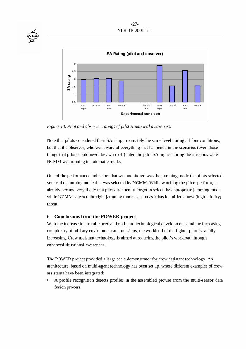
Situational Awareness (SA) as rated by the pilots themselves and by an observer is visualised infigure 13
1 Z scores are standardised scores. They were calculated using the following formula: Z score = (raw score - mean) / standarddeviation.
-27-NLR-TP-2001-611
SA Rating (pilot and observer)
6,5
7
7,5
8
8,5
9
autohigh
manual autolow
manual NCMMWL
autohigh
manual autolow
manual
Experimental condition
SA ra
ting
Figure 13. Pilot and observer ratings of pilot situational awareness.
Note that pilots considered their SA at approximately the same level during all four conditions,but that the observer, who was aware of everything that happened in the scenarios (even thosethings that pilots could never be aware off) rated the pilot SA higher during the missions wereNCMM was running in automatic mode.
One of the performance indicators that was monitored was the jamming mode the pilots selectedversus the jamming mode that was selected by NCMM. While watching the pilots perform, italready became very likely that pilots frequently forgot to select the appropriate jamming mode,while NCMM selected the right jamming mode as soon as it has identified a new (high priority)threat.
6 Conclusions from the POWER projectWith the increase in aircraft speed and on-board technological developments and the increasingcomplexity of military environment and missions, the workload of the fighter pilot is rapidlyincreasing. Crew assistant technology is aimed at reducing the pilot’s workload throughenhanced situational awareness.
The POWER project provided a large scale demonstrator for crew assistant technology. Anarchitecture, based on multi-agent technology has been set up, where different examples of crewassistants have been integrated:• A profile recognition detects profiles in the assembled picture from the multi-sensor data
fusion process.

-28-NLR-TP-2001-611
• A manoeuvre prediction can be used in dogfight situations to predict and anticipate enemyaircraft's manoeuvres.
• NCMM is the NLR Counter Measure Manager to assist the pilot in taking counter measuresagainst ground threats.
The focus of the project has been decision support in operational fighter aircraft scenariosthrough the integration of AIP and HF aspects in the military cockpit. We have shown theintegration of these areas by examining different AIP techniques and their integration in thecockpit. Display design has been carefully taken place to take the HF aspects into account. Astep has been made in the quantitative and qualitative effects of on-board decision supportfunctions in an experiment where operational F-16 pilots participated.
We examined the possibilities for real-time and especially any-time reasoning in on-boardapplication. Any-time algorithms provide the possibility to interrupt the reasoning process atany moment thus enabling optimal processor performance and use. Promising techniques areBayesian Belief Networks and case based reasoning.
Future work will be directed to the maintenance of the architecture provided and to the furtherintegration of agents, both functional and for system control and monitoring. More work needsto be carried out to reasoning with uncertainty. The environment can be used to facility moreexperiments.
7 References
[Barrouil 1999] Barrouil, Cl. et.al., TANDEM: An Agent-oriented Approach for Mixed SystemManagement in Air Operations, NATO Research and Technology Organisation symposiumon Advanced System Management and System Integration Technologies for ImprovedTactical Operations, Florence, Italy, September 1999.
[Boers 1999] Boers, E.J.W. et.al., PoWeR-II: State of the Art in Crew Assistants, NLR,Amsterdam, NLR-TR-99155, December 1999.
[Bossé 1999] Bossé, E., P. Valin, and A. Jouan, A Multi-Agent Data Fusion Architecture for anAirborne mission Management System, NATO Research and Technology Organisationsymposium on Advanced System Management and System Integration Technologies forImproved Tactical Operations, Florence, Italy, September 1999.
[Colluci 1995] Colluci, F., Rotorcraft Pilot’s Associate update: The Army’s Largest Science andTechnology program, Vertiflite, March/April, 1995.
[Eertink 2000] Eertink, B.J., F.W. Uilhoorn, F. Tempelman, H.F.R. Arciszewski, NTP SPEWManager final report, NLR, Amsterdam, NLR-CR-2000-562, October 2000.

-29-NLR-TP-2001-611
[Frey 1999] Frey, A., A. Lenz, and R. Onken, Core Elements of the Cognitive Assistant SystemCAMA, NATO Research and Technology Organisation symposium on Advanced MissionManagement and System Integration Technologies for Improved Tactical Operations,Florence, Italy, September 1999.
[Harris 1986] Harris, R.L., B.J. Glover, and A.A. Spady, Analytical Techniques of PilotScanning Behavior and Their Application, NASA Hampton, Technical Paper 2525.
[Holmes 1995] Holmes, D.I., and J.P. Retelle, The Pilot’s Associate, Exploiting the IntelligentAdvantage, Knowledge Based System Applications for Guidance and Control, AGARD CP474, AGARD, NATO, Neuilly-sur-Seine, France, 1995.
[Hoogeboom 1997] Hoogeboom, P.J., Human Factors Evaluations, Data Analysis andReduction Techniques (HEART) - General Description, NLR, Amsterdam, NLR-CR-97597, 1997.
[Jensen 1996] Jensen, F.V., An Introduction to Bayesian Belief Networks, UCL Press, 1996.[Mooij 1996] Mooij & Associaties (G.D.R. Zon and H.A. Mooij), GazeTracker for Real-time,
Omni-directional and Digital Point-of-Gaze Determination - Installation and OperationGuide, EPOS Version 4.3, MA-95-15, December 1996.
[Mulder 1988] Mulder, L.J.M., Assessment of Cardiovascular Reactivity by Means of SpectralAnalysis, Thesis, RijksUniversiteit Groningen, The Netherlands.
[Onken 1997] Onken, R., Functional Development and Field Test of CASSY – A KnowledgeBased Cockpit Assistant System, Knowledge-Based Functions in Aerospace Systems,AGARD Lecture Series 200, AGARD, Neuilly-sur-Seine, France, 1995.
[Pearl 1988] Pearl, J., Probabilistic Reasoning in Intelligent Systems: Networks of PlausibleInference, Morgan Kaufmann, San Mateo, 1988.
[Stein 1987] Stein, K.J., Lockheed Developing Electronic Co-pilot in Support of ATF ProgramEffort, Aviation Week & Space Technology, pp. 73-76, August 1987.
[Stern 1994] Stern, J.A., Blink Rate: A Possible Measure of Fatigue, Human Factors 36(2), 285- 297.
[Strohal 1997] Strohal, M, and R. Onken, The Crew Assistant Military Aircraft (CAMA), 7th
International Conference on Human-Computer Interaction, San Francisco, CA, August1997.
[Taylor 1998] Taylor, R.M., The Human-Electronic Crew: Human Computer CollaborativeTeamworking, 1st NATO RTO Human Factors and Medical Panel Symposium onCollaborative Crew Performance in Complex Operational Systems, Edinburgh, UK, April1998.
[Taylor 2000] Taylor, R.M., Cognitive Cockpit Engineering: Coupling Functional StateAssessment, Task Knowledge Management and Decision Support for Context SensitiveAiding, Taylor, R.M. et.al., TTCP Technical Panel 7, Human Factors in AircraftEnvironments, Workshop on Cognitive Engineering, Dayton, OH, May 2000.

-30-NLR-TP-2001-611
[Tempelman 1999] Tempelman, F., Real-Time Self-Protection Electronic Warfare Managementin Fighter Aircraft, NATO Research and Technology Organisation symposium onAdvanced System Management and System Integration Technologies for ImprovedTactical Operations, Florence, Italy, September 1999.
[Urlings 1995] Urlings, P.J.M., JJ. Brants, R.G. Zuidgeest, and B.J. Eertink, Crew AssistantArchitecture, RTP 6.5 Crew Assistant, EUCLID CEPA 6, D-CAA-WP1.3-NL/03A, NLRAmsterdam, 1995.
[Van Gerwen 2000-1] Van Gerwen, M.J.A.M., E. Rondema, F. Tempelman, and H.E. Veldman,Knowledge and Reasoning in Crew Assistant Applications, NLR, Amsterdam, NLR-TR-2000-650, December 2000.
[Van Gerwen 2000-2] Van Gerwen, M.J.A.M. and E. Rondema, PoWeR-II: Anytime BayesianBelief Networks, Proposed Solution, NLR, Amsterdam, NLR-TR-2000-654, December2000.
[Verhoeven 2000] Verhoeven, R.P.M., et.al., PoWeR-II: Crew Assistant Systems: HumanFactors Aspects and HMI Considerations, NLR, Amsterdam, NLR-TR-2000-649, March2001
[Wilson 1987] Wilson, G.F., et.al., Physiological Data Used to Measure Pilot Workload inActual Flight and Simulator Conditions, Proceedings of Human Factors Society - 31stAnnual Meeting, 1987.
[Wilson 1993] Wilson, G.F., A. Badeau, and V. Gawron, Evaluation of Two Inflight SensorsUsing Heart Rate and Eye Blink Measure, Aviation Psychology, 1993.
[Yannonne 1985] Yannone, R.M., The Role of Expert Systems in the Advanced Tactical Fighterof the 1990’s, Proceedings of the 1985 National Aerospace and Electronics Conference,Dayton OH, IEEE, New York, 1985.
[Zuidgeest 1995] Zuidgeest, R. Advanced Information Processing for On-Board Crew Assistant,NLR News, number 21, July 1995.