on applying controlled switching to transmission...
TRANSCRIPT
1
On Applying Controlled Switching to TransmissionLines: Case Studies
Karcius M. C. Dantas, Washington L. A. Neves, Damásio Fernandes Jr., Gustavo A. Cardoso, Luiz C. Fonseca
Abstract— The goal of this work is to evaluate the controlledswitching method when applied to different transmission linesat the North-Northeast Brazilian Power System Grid taking intoaccount trapped charges and shunt compensation effects. Thecontrolled switching algorithm is implemented in the AlternativeTransients Program (ATP) using the MODELS language and itsperformance is compared to the pre-insertion resistors method bymeans of EMTP simulations. Situations where transmission linesare transposed and not transposed are considered. The resultsattest the efficiency of the controlled switching method, limitingswitching overvoltages to 1.45 per unit for shunt compensatedtransmission lines.
Index Terms— Controlled Switching, Electromagnetic Tran-sients, Switching Overvoltages, Transmission Lines
I. INTRODUCTION
CONTROLLED switching is the term used to describe theapplication of electronic control devices to control the
mechanical closing or opening of circuit breaker contacts [1],[2]. It has been a desirable method for stress reduction and inparticular for reduction of switching overvoltages, becomingan issue of widespread interest to the utilities and manu-facturers [3], [4]. Its benefit and feasibility were presentedby CIGRE Task Force 13.00.1, with emphasis on mitigationof switching surges and related economical features due tothe reduction of insulation levels of large capacitor banks,elimination of circuit breakers auxiliary chamber, compactionof transmission lines and reduction of arresters rating [5], [6].
Regarding to line circuit-breakers, controlled closing and re-closing may provide an increase of power apparatus life timeand improvement on power quality. In addition, it eliminatesthe need for pre-insertion resistors, and may limit switchingovervoltages to acceptable values, especially when used inconjunction with surge arresters [7]. The suitable makinginstant for controlled switching of an unloaded line is thetime in which the voltage across the circuit breaker contactsfor each phase is zero and the predicted time span betweenthe closing instant of the first and the last pole is as small aspossible [8].
This work was supported by Brazilian National Research Council (CNPq).K. M. C. Dantas, W. L. A. Neves, D. Fernandes Jr. and G. A. Cardosoare with Department of Electrical Engineering at Federal University ofCampina Grande, 882 Aprígio Veloso Av, Bodocongó, Campina Grande- PB, CEP: 58.109-970, Brazil. E-mail: (karcius, waneves, damasio, gcar-doso)@ee.ufcg.edu.br. Luiz C. Fonseca is with Companhia Hidro Elétrica doSão Francisco (CHESF), 333 Delmiro Golveia St, San Martin, Recife - PE,CEP: 50.761-901, Brazil. E-mail: [email protected].
Paper submitted to the International Conference on Power Systems Transients(IPST2009) in Kyoto, Japan June 3-6, 2009
This paper aims to evaluate the controlled switching methodwhen applied to different transmission lines at the North-Northeast Brazilian Power System Grid taking into accounttrapped charges and shunt compensation effects. The methodis based on a very simple zero crossing algorithm withconstraints and is implemented in the Alternative TransientsProgram (ATP) [9] using the MODELS language [10].
Controlled switching has been evaluated by means of EMTPsimulations using fully transposed transmission lines [8]. Here,situations where transmission lines are not 100% balancedare considered and the controlled switching performance iscompared to the pre-insertion resistors method. The resultsattest the efficiency of the controlled switching, limitingswitching overvoltages to 1.45 per unit for shunt compensatedtransmission lines considering all case studies. Besides, thecontrolled switching method performed well for both 100%and not 100% balanced transmission lines.
II. CONTROLLED SWITCHING FUNDAMENTALS
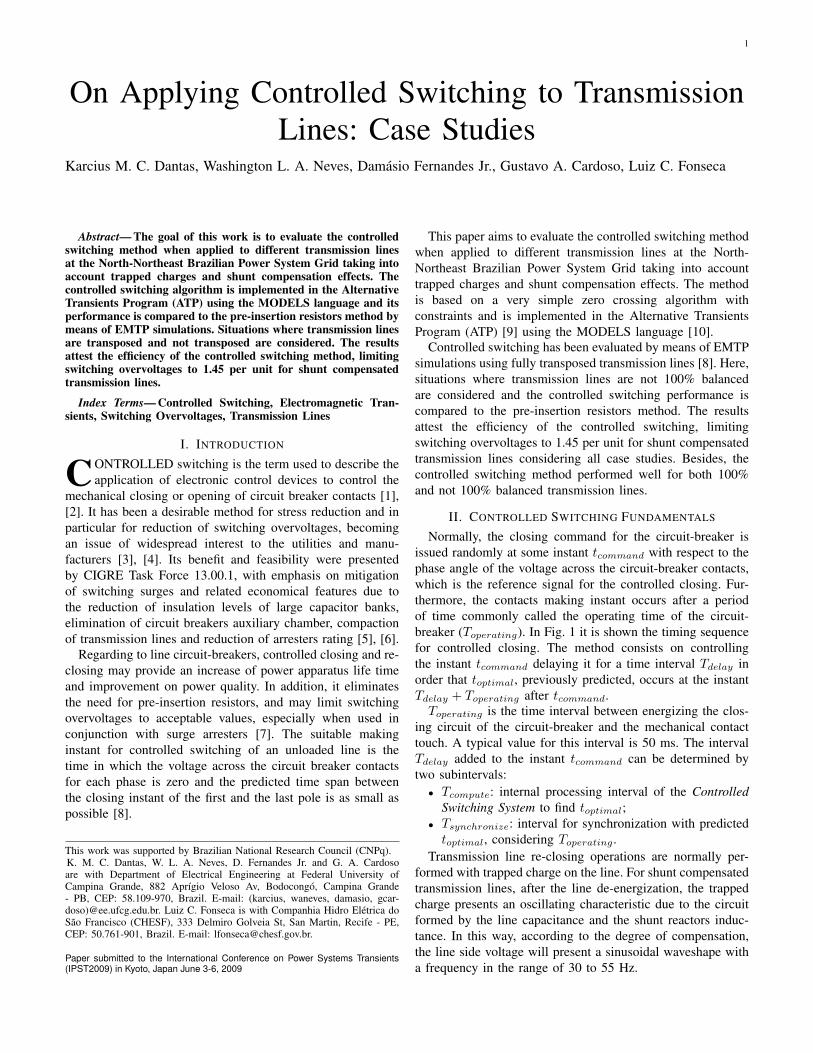
Normally, the closing command for the circuit-breaker isissued randomly at some instant tcommand with respect to thephase angle of the voltage across the circuit-breaker contacts,which is the reference signal for the controlled closing. Fur-thermore, the contacts making instant occurs after a periodof time commonly called the operating time of the circuit-breaker (Toperating). In Fig. 1 it is shown the timing sequencefor controlled closing. The method consists on controllingthe instant tcommand delaying it for a time interval Tdelay inorder that toptimal, previously predicted, occurs at the instantTdelay + Toperating after tcommand.
Toperating is the time interval between energizing the clos-ing circuit of the circuit-breaker and the mechanical contacttouch. A typical value for this interval is 50 ms. The intervalTdelay added to the instant tcommand can be determined bytwo subintervals:• Tcompute: internal processing interval of the Controlled
Switching System to find toptimal;• Tsynchronize: interval for synchronization with predicted
toptimal, considering Toperating .Transmission line re-closing operations are normally per-
formed with trapped charge on the line. For shunt compensatedtransmission lines, after the line de-energization, the trappedcharge presents an oscillating characteristic due to the circuitformed by the line capacitance and the shunt reactors induc-tance. In this way, according to the degree of compensation,the line side voltage will present a sinusoidal waveshape witha frequency in the range of 30 to 55 Hz.
2
Fig. 1. Schematic controlled closing sequence.
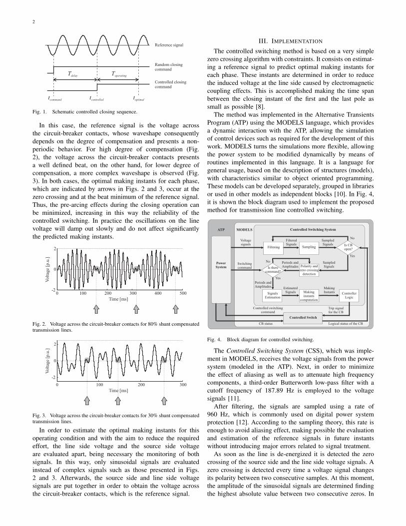
In this case, the reference signal is the voltage acrossthe circuit-breaker contacts, whose waveshape consequentlydepends on the degree of compensation and presents a non-periodic behavior. For high degree of compensation (Fig.2), the voltage across the circuit-breaker contacts presentsa well defined beat, on the other hand, for lower degree ofcompensation, a more complex waveshape is observed (Fig.3). In both cases, the optimal making instants for each phase,which are indicated by arrows in Figs. 2 and 3, occur at thezero crossing and at the beat minimum of the reference signal.Thus, the pre-arcing effects during the closing operation canbe minimized, increasing in this way the reliability of thecontrolled switching. In practice the oscillations on the linevoltage will damp out slowly and do not affect significantlythe predicted making instants.
Fig. 2. Voltage across the circuit-breaker contacts for 80% shunt compensatedtransmission lines.
Fig. 3. Voltage across the circuit-breaker contacts for 30% shunt compensatedtransmission lines.
In order to estimate the optimal making instants for thisoperating condition and with the aim to reduce the requiredeffort, the line side voltage and the source side voltageare evaluated apart, being necessary the monitoring of bothsignals. In this way, only sinusoidal signals are evaluatedinstead of complex signals such as those presented in Figs.2 and 3. Afterwards, the source side and line side voltagesignals are put together in order to obtain the voltage acrossthe circuit-breaker contacts, which is the reference signal.
III. IMPLEMENTATION
The controlled switching method is based on a very simplezero crossing algorithm with constraints. It consists on estimat-ing a reference signal to predict optimal making instants foreach phase. These instants are determined in order to reducethe induced voltage at the line side caused by electromagneticcoupling effects. This is accomplished making the time spanbetween the closing instant of the first and the last pole assmall as possible [8].
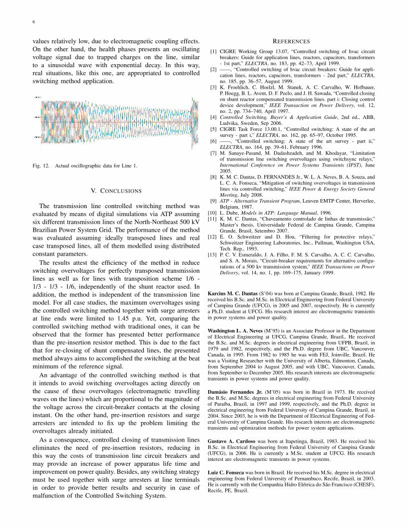
The method was implemented in the Alternative TransientsProgram (ATP) using the MODELS language, which providesa dynamic interaction with the ATP, allowing the simulationof control devices such as required for the development of thiswork. MODELS turns the simulations more flexible, allowingthe power system to be modified dynamically by means ofroutines implemented in this language. It is a language forgeneral usage, based on the description of structures (models),with characteristics similar to object oriented programming.These models can be developed separately, grouped in librariesor used in other models as independent blocks [10]. In Fig. 4,it is shown the block diagram used to implement the proposedmethod for transmission line controlled switching.
Fig. 4. Block diagram for controlled switching.
The Controlled Switching System (CSS), which was imple-ment in MODELS, receives the voltage signals from the powersystem (modeled in the ATP). Next, in order to minimizethe effect of aliasing as well as to attenuate high frequencycomponents, a third-order Butterworth low-pass filter with acutoff frequency of 187.89 Hz is employed to the voltagesignals [11].
After filtering, the signals are sampled using a rate of960 Hz, which is commonly used on digital power systemprotection [12]. According to the sampling theory, this rate isenough to avoid aliasing effect, making possible the evaluationand estimation of the reference signals in future instantswithout introducing major errors related to signal treatment.
As soon as the line is de-energized it is detected the zerocrossing of the source side and the line side voltage signals. Azero crossing is detected every time a voltage signal changesits polarity between two consecutive samples. At this moment,the amplitude of the sinusoidal signals are determined findingthe highest absolute value between two consecutive zeros. In

3
addition, the period of these signals are determined by meansof two consecutive zero crossing.
Then, when the switching command is issued and basedon the last values determined for the period, amplitude andzero crossing of the sinusoidal signals, the CSS estimatesthe reference signals in future instants taking into accountToperating . In this way, a list of possible optimal makinginstants can be determined for each phase. Now, taking asreference the switching command, which occurs at a randominstant tcommand, the Controller Logic acts delaying thiscommand for a time interval necessary to accomplish theswitching operation of each phase at an optimal making instantin the future (toptimal) in a way that the time span betweenthe closing instant of the first and the last pole is as small aspossible.
The Controlled Switch in the MODELS is responsible forthe coordination of the switching command for the switches inthe power system modeled at the ATP. These switches emulatethe operation of the circuit-breaker. So, when the ControllerLogic acts, the trip signal for the switches at the ATP is sent byMODELS and the switching command for the circuit-breakeris controlled via digital simulations. Yet, this Controlled Switchhas the task of indicating the logic state of the circuit-breaker(open or closed) to the CSS, in order that the system may actas soon as the circuit-breaker is opened.
IV. CONTROLLED SWITCHING EVALUATION
The controlled switching method is evaluated by means ofdigital simulations via ATP. It is analyzed the re-closing of six500 kV shunt compensated transmission lines at the North-Northeast Brazilian Power System Grid, whose electrical-geographic map is shown in Fig. 5. A dead time of 500 mswas considered for all case studies.
Fig. 5. North-Northeast Brazilian Power System Grid.
The sequence data of the lines as well as its extension arepresented in Table I. In Table II, the transmission lines shuntcompensation data are presented. The shunt reactors of Lines1 and 3 have respectively a 150 Ω neutral resistance and a 585Ω neutral reactor. The neutral of the other shunt reactors aresolidly grounded. The reactor winding resistances range from1.58 to 6.12 Ω. The geometry of Line 6 is shown in Fig. 6and its conductor data in Table III.
TABLE ITRANSMISSION LINES EXTENSIONS AND SEQUENCE PARAMETERS.
Lines Sequence R (Ω/km) X (Ω/km) ωC (µf/km)
Line 1 Zero 0,3996 0,9921 3,0839(169,0 km) Positive 0,0333 0,3170 5,2033
Line 2 Zero 0,2416 0,8723 3,4484(268,7 km) Positive 0,0255 0,2821 5,8808
Line 3 Zero 0,3818 1,407 3,246(205,6 km) Positive 0,0246 0,3219 5,150
Line 4 Zero 0,3240 1,3580 2,781(319,0 km) Positive 0,0227 0,3127 5,159
Line 5 Zero 0,2254 0,9437 3,5919(341,0 km) Positive 0,0170 0,2685 6,2026
Line 6 Zero 0,3493 1,3490 3,538(248,4 km) Positive 0,0252 0,2653 6,2794
TABLE IISHUNT COMPENSATION DATA.
Transmission Terminal Reactive Power (Mvar) CompensationLine Sending Receiving Degree (%)
Line 1 - 100 45Line 2 150 150 76Line 3 200 104 115Line 4 150 150 73Line 5 292 146 83Line 6 - 150 38
Fig. 6. Geometry of Line 6.

4
TABLE IIICONDUCTORS DATA OF LINE 6.
Parameters Phase Conductor Ground WireType Grosbeak EHS 3/8”
Outside diameter (cm) 2,515 0,914GMR (cm) 1,0211 0,8949
AC Resistence (Ω/km) 0,0996 4,307
A. Case Studies
In order to properly evaluate the method, statistical scatterwith respect to the operating time of the circuit-breaker mustbe considered. In this way Toperating is given as a function ofthe nominal operating time of the circuit-breaker (Tnominal)and of the statistical scatter on the operating time (∆Tstatistic),as follows.
Toperating = Tnominal + ∆Tstatistic . (1)
The statistical scatter can be represented by statisticalswitches, modeled at ATP, with a Gaussian probability dis-tribution and described by a standard deviation σ. Accordingto [1], the maximum scatter may be approximated by Equation(2). So, considering a maximum scatter of 2 ms, the standarddeviation is approximately 0.67 ms.
∆Tstatistic = 3σ . (2)
Another characteristic that must be considered is the rateof decay of the dielectric strength of the circuit-breaker(dvCB/dt). In order to avoid the pre-arcing effects, it wasconsidered that the dvCB/dt is greater than the maximumvalue of the power system voltage derivative [13].
For the case studies, the lines 1 to 5 are consideredperfectly transposed and modelled using distributed constant-parameters. In addition, the steady-state is adjusted to 550kV, which is the maximum normal operating condition atthe 500 kV Brazilian Power System. The value of 550 kVis used as reference in this paper. For all simulations, 420kV class metal oxide arresters (MOA) are connected at bothterminals of the transmission lines and are modeled accordingto their V-I characteristic curves obtained from [4]. This MOAis normally used at the 500 kV Brazilian Power System andhas a protection level of 830 kV at 2 kA.
The controlled switching performance is compared to thepre-insertion resistor’s (PIR) method, using a resistance of 400Ω and a insertion time of 8 ms, which are typical values usedat the Brazilian Power System. The optimum resistor valueis determined by means of studies on overvoltages along thelines due to the insertion and short-circuit of the resistors. Itwas not observed at the simulations significative difference atthe voltage profile along the lines when using resistor valuesbetween 200 and 400 Ω.
For each case analyzed in this paper, a total of 300 statisticalsimulations was performed and the maximum overvoltagevalues along the lines are shown in Fig. 7. In order tomake easier the comparative analysis of the used methods formitigation of switching overvoltages in transmission lines, it isshown in Table IV the maximum overvoltage values for eachsituation considered.
From these statistical values, it can be observed that theapplication of pre-insertion resistor or controlled switching to-gether with surge arresters are effective in reducing switchingovervoltages along the lines. Among all cases, the maximumovervoltage value using the controlled switching method was1.45 p.u., while using the pre-insertion resistor this value was1.80 p.u.
Fig. 7. Overvoltages along the transmission lines: (a) Line 1; (b) Line 2; (c)Line 3; (d) Line 4; (e) Line 5.
TABLE IVMAXIMUM OVERVOLTAGE VALUES
Transmission Overvoltage (p.u.)
Line MOA PIR-MOA CSS-MOA
Line 1 2,45 1,60 1,40Line 2 2,05 1,60 1,30Line 3 1,95 1,65 1,30Line 4 2,35 1,80 1,40Line 5 2,30 1,70 1,45
MOA - Metal Oxide Arrester.PIR - Pre-insertion Resistor together with MOA.CSS - Controlled Switching System together with MOA.
B. Transmission line with three transposition towers
At section IV-A the performance of the controlled switchingmethod was evaluated using perfectly transposed transmissionlines. This consideration contributes to the effectiveness ofthe method due to the fact that the negative and positive line

5
sequence parameters are the same. So, for shunt compensatedtransmission lines, the line side voltage after the line de-energization presents mainly only one frequency component,which is related to the positive sequence parameters.
However, in practical situations, the lines are not 100%balanced. On the other hand, at the Brazilian Power SystemGrid, normally it is used a transposition scheme known as1/6 - 1/3 - 1/3 - 1/6, which uses three transposition towersas ilustrated in Fig. 8. In this way, the lines are divided intofour parts, respectively with 1/6, 1/3, 1/3 and 1/6 of its length.In this section, the controlled switching method is applied totransmission line with this transposition scheme.
Fig. 8. Transposition scheme 1/6 - 1/3 - 1/3 - 1/6.
Due to availability of data, Line 6 was used for thispurpose. As a matter of comparison, the line was modeledwith distributed constant parameters in two different ways:perfectly transposed and not transposed with the transpositionscheme above. In Fig. 9 it is shown the line side voltages forthe perfectly transposed line re-closing using the controlledswitching method. It can be observed that during the re-closingoperation, practically there is no overvoltages. In Fig. 10 it isshown the line side voltages for the same re-closing operationconsidering the line with the transposition scheme of Fig. 8.Once more, during the re-closing operation, practically thereis no overvoltages, attesting the efficiency of the method.
In this way, it can be concluded that the performance of thecontrolled switching method was satisfactory for both cases:lines perfectly transposed and with the transposition scheme1/6 - 1/3 - 1/3 - 1/6. In fact, when using this transpositionscheme, a certain degree of symmetry is attributed to theline. In this way, as illustrated in Fig. 11, it can be observedthat the line side voltages for each phase are practically thesame when considering a line perfectly transposed or with thetransposition scheme mentioned above. This fact justify thegood performance of the method for both situations.
Fig. 9. Voltage signals for re-closing of a line perfectly transposed.
Fig. 10. Voltage signals for re-closing of a line with transposition scheme1/6 - 1/3 - 1/3 - 1/6.
Fig. 11. Comparison of voltage signals: line perfectly transposed and linewith transposition scheme 1/6 - 1/3 - 1/3 - 1/6.
In Fig. 12 it is shown an actual oscillographic data forLine 1. It can be observed from this record the occurrenceof a single-phase to ground fault, which cause the line de-energization and the line re-closing in the following. After de-energization, the phase with fault presents a voltage signal with
6
values relatively low, due to electromagnetic coupling effects.On the other hand, the health phases presents an oscillatingvoltage signal due to trapped charges on the line, similarto a sinusoidal wave with exponential decay. In this way,real situations, like this one, are appropriated to controlledswitching method application.
Fig. 12. Actual oscillographic data for Line 1.
V. CONCLUSIONS
The transmission line controlled switching method wasevaluated by means of digital simulations via ATP assumingsix different transmission lines of the North-Northeast 500 kVBrazilian Power System Grid. The performance of the methodwas evaluated assuming ideally transposed lines and realcase transposed lines, all of them modelled using distributedconstant parameters.
The results attest the efficiency of the method in reduceswitching overvoltages for perfectly transposed transmissionlines as well as for lines with transposition scheme 1/6 -1/3 - 1/3 - 1/6, independently of the shunt reactor used. Inaddition, the method is independent of the transmission linemodel. For all case studies, the maximum overvoltages usingthe controlled switching method together with surge arrestersat line ends were limited to 1.45 p.u. Yet, comparing thecontrolled switching method with traditional ones, it can beobserved that the former has presented better performancethan the pre-insertion resistor method. This is due to the factthat for re-closing of shunt compensated lines, the presentedmethod always aims to accomplished the switching at the beatminimum of the reference signal.
An advantage of the controlled switching method is thatit intends to avoid switching overvoltages acting directly onthe cause of these overvoltages (electromagnetic travellingwaves on the lines) which are proportional to the magnitude ofthe voltage across the circuit-breaker contacts at the closinginstant. On the other hand, pre-insertion resistors and surgearresters are intended to fix up the problem limiting theovervoltages already initiated.
As a consequence, controlled closing of transmission lineseliminates the need of pre-insertion resistors, reducing inthis way the costs of transmission line circuit breakers andmay provide an increase of power apparatus life time andimprovement on power quality. Besides, any switching strategymust be used together with surge arresters at line terminalsin order to provide better results and security in case ofmalfunction of the Controlled Switching System.
REFERENCES
[1] CIGRE Working Group 13.07, “Controlled switching of hvac circuitbreakers: Guide for application lines, reactors, capacitors, transformers- 1st part,” ELECTRA, no. 183, pp. 42–73, April 1999.
[2] ——, “Controlled switching of hvac circuit breakers: Guide for appli-cation lines, reactors, capacitors, transformers - 2nd part,” ELECTRA,no. 185, pp. 36–57, August 1999.
[3] K. Froehlich, C. Hoelzl, M. Stanek, A. C. Carvalho, W. Hofbauer,P. Hoegg, B. L. Avent, D. F. Peelo, and J. H. Sawada, “Controlled closingon shunt reactor compensated transmission lines. part i: Closing controldevice development,” IEEE Transaction on Power Delivery, vol. 12,no. 2, pp. 734–740, April 1997.
[4] Controlled Switching, Buyer’s & Application Guide, 2nd ed., ABB,Ludvika, Sweden, Sep 2006.
[5] CIGRE Task Force 13.00.1, “Controlled switching: A state of the artsurvey - part i,” ELECTRA, no. 162, pp. 65–97, October 1995.
[6] ——, “Controlled switching: A state of the art survey - part ii,”ELECTRA, no. 164, pp. 39–61, February 1996.
[7] M. Sanaye-Pasand, M. Dadashzadeh, and M. Khodayar, “Limitationof transmission line switching overvoltages using switchsync relays,”International Conference on Power Systems Transients (IPST), June2005.
[8] K. M. C. Dantas, D. FERNANDES Jr., W. L. A. Neves, B. A. Souza, andL. C. A. Fonseca, “Mitigation of switching overvoltages in transmissionlines via controlled switching,” IEEE Power & Energy Society GeneralMeeting, July 2008.
[9] ATP - Alternative Transient Program, Leuven EMTP Center, Herverlee,Belgium, 1987.
[10] L. Dube, Models in ATP: Language Manual, 1996.[11] K. M. C. Dantas, “Chaveamento controlado de linhas de transmissão,”
Master’s thesis, Universidade Federal de Campina Grande, CampinaGrande, Brasil, Setembro 2007.
[12] E. O. Schweitzer and D. Hou, “Filtering for protective relays,”Schweitzer Engineering Laboratories, Inc., Pullman, Washington USA,Tech. Rep., 1993.
[13] P. C. V. Esmeraldo, J. A. Filho, F. M. S. Carvalho, A. C. C. Carvalho,and S. A. Morais, “Circuit-breaker requirements for alternative configu-rations of a 500 kv transmission system,” IEEE Transactions on PowerDelivery, vol. 14, no. 1, pp. 169–175, January 1999.
Karcius M. C. Dantas (S’04) was born at Campina Grande, Brazil, 1982. Hereceived his B.Sc. and M.Sc. in Electrical Engineering from Federal Universityof Campina Grande (UFCG), in 2005 and 2007, respectively. He is currentlya Ph.D. student at UFCG. His research interest are electromagnetic transientsin power systems and power quality.
Washington L. A. Neves (M’95) is an Associate Professor in the Departmentof Electrical Engineering at UFCG, Campina Grande, Brazil,. He receivedthe B.Sc. and M.Sc. degrees in electrical engineering from UFPB, Brazil, in1979 and 1982, respectively, and the Ph.D. degree from UBC, Vancouver,Canada, in 1995. From 1982 to 1985 he was with FEJ, Joinville, Brazil. Hewas a Visiting Researcher with the University of Alberta, Edmonton, Canada,from September 2004 to August 2005, and with UBC, Vancouver, Canada,from September to December 2005. His research interests are electromagnetictransients in power systems and power quality.
Damásio Fernandes Jr. (M’05) was born in Brazil in 1973. He receivedthe B.Sc. and M.Sc. degrees in electrical engineering from Federal Universityof Paraíba, Brazil, in 1997 and 1999, respectively, and the Ph.D. degree inelectrical engineering from Federal University of Campina Grande, Brazil, in2004. Since 2003, he is with the Department of Electrical Engineering of Fed-eral University of Campina Grande. His research interests are electromagnetictransients and optimization methods for power system applications.
Gustavo A. Cardoso was born at Itapetinga, Brazil, 1983. He received hisB.Sc. in Electrical Engineering from Federal University of Campina Grande(UFCG), in 2006. He is currently a M.Sc. student at UFCG. His researchinterest are electromagnetic transients in power systems.
Luiz C. Fonseca was born in Brazil. He received his M.Sc. degree in electricalengineering from Federal University of Pernambuco, Recife, Brazil, in 2003.He is currently with the Companhia Hidro Elétrica do São Francisco (CHESF),Recife, PE, Brazil.