omega carver user's guide · to resume carving. starting the dust collection system click the...
TRANSCRIPT

OMEGA® CarverUser's Guide
PN-1898-D 16 JULY 2010

Information in this document is subject to change without notice.
No part of this document may be reproduced or transmitted in any form or by any means, electronic or mechanical, for any purpose, without the expressed written consent of Ohio Willow Wood.
© Copyright 2010 Ohio Willow Wood. All rights reserved.
OMEGA® and Tracer® are registered trademarks of Ohio Willow Wood.
Windows® is a registered trademarks of Microsoft® Corporation.
Names and examples used in this document are fictitious unless otherwise noted.
Published By Ohio Willow Wood Mt. Sterling, Ohio
USA
2
3
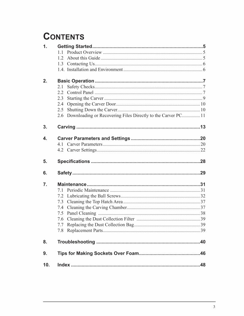
Contents1. Getting Started ...................................................................................5
1.1 Product Overview ................................................................................... 51.2 About this Guide ..................................................................................... 51.3 Contacting Us .......................................................................................... 61.4. Installation and Environment .................................................................. 6
2. Basic Operation .................................................................................72.1 Safety Checks .......................................................................................... 72.2 Control Panel .......................................................................................... 72.3 Starting the Carver .................................................................................. 92.4 Opening the Carver Door ...................................................................... 102.5 Shutting Down the Carver ..................................................................... 102.6 Downloading or Recovering Files Directly to the Carver PC ............... 11
3. Carving .............................................................................................13
4. Carver Parameters and Settings ....................................................204.1 Carver Parameters ................................................................................. 204.2 Carver Settings ...................................................................................... 22
5. Specifications ..................................................................................28
6. Safety ................................................................................................29
7. Maintenance .....................................................................................317.1 Periodic Maintenance ........................................................................... 317.2 Lubricating the Ball Screws .................................................................. 327.3 Cleaning the Top Hatch Area ................................................................ 377.4 Cleaning the Carving Chamber ............................................................. 377.5 Panel Cleaning ..................................................................................... 387.6 Cleaning the Dust Collection Filter ..................................................... 397.7 Replacing the Dust Collection Bag ....................................................... 397.8 Replacement Parts ................................................................................. 39
8. Troubleshooting ..............................................................................40
9. Tips for Making Sockets Over Foam ..............................................46
10. Index .................................................................................................48

4
5
1. GettinGstarted
1.1 Product Overview
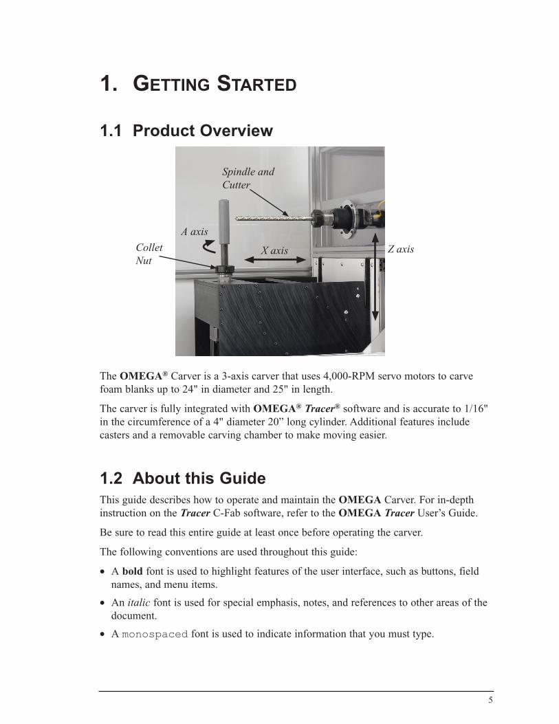
The OMEGA® Carver is a 3-axis carver that uses 4,000-RPM servo motors to carve foam blanks up to 24" in diameter and 25" in length.
The carver is fully integrated with OMEGA® Tracer® software and is accurate to 1/16" in the circumference of a 4" diameter 20” long cylinder. Additional features include casters and a removable carving chamber to make moving easier.
1.2 About this GuideThis guide describes how to operate and maintain the OMEGA Carver. For in-depth instruction on the Tracer C-Fab software, refer to the OMEGA Tracer User’s Guide.
Be sure to read this entire guide at least once before operating the carver.
The following conventions are used throughout this guide:
• A bold font is used to highlight features of the user interface, such as buttons, field names, and menu items.
• An italic font is used for special emphasis, notes, and references to other areas of the document.
• A monospaced font is used to indicate information that you must type.
Spindle and Cutter
Collet Nut
A axis
X axis Z axis

1.3 Contacting UsYou can contact Ohio Willow Wood at 800-848-4930 or via the Internet at www.owwco.com.
1.4. Installation and EnvironmentThe OMEGA Carver is to be installed and serviced only by Ohio Willow Wood personnel.
The environment in which the carver is installed should include the following:
• A clean, dry area with as little dust as possible. Avoid exposure to rain and water droplets.
• A flat, stable, and level floor
• Suitable lighting
• A workspace area of 98 inches by 45 inches for installation of the carver and dust collection system
• No electrical machines or devices within 65 feet that may produce high-frequency noise. Examples of such machinery include: • Arc welder• Resistance welder• High frequency drier• Electric discharge machine
• Input voltage of 230V Single Phase at 60Hz
• Input current of 20A
• Internet access
6
7
2. BasiCoperation
2.1 Safety ChecksIf any of the following abnormalities are detected, take corrective action prior to using the carver:
• Abnormal noises or vibration
• Damage to the carver
• Software/hardware not operating in the manner intended
• Cooling fans not functioning
• Error messages in the display
2.2 Control Panel
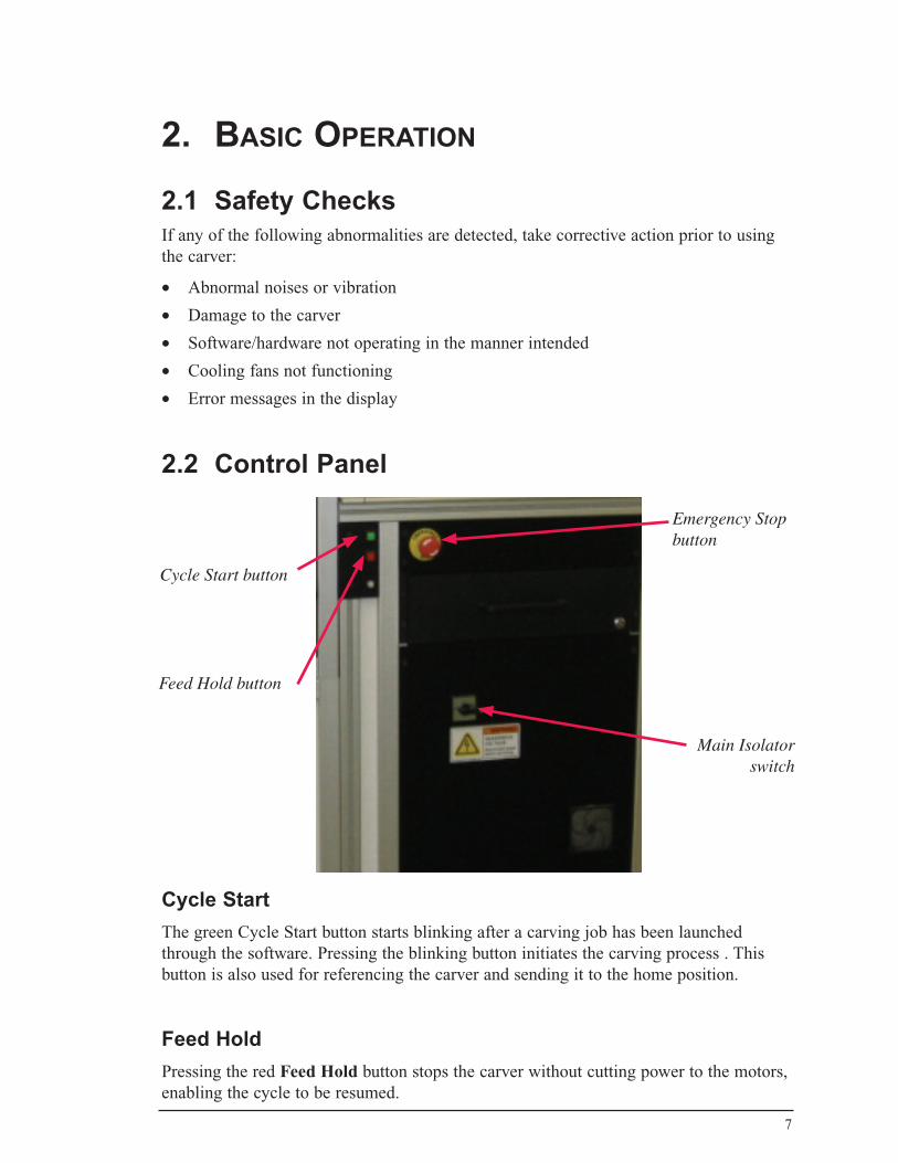
Cycle StartThe green Cycle Start button starts blinking after a carving job has been launched through the software. Pressing the blinking button initiates the carving process . This button is also used for referencing the carver and sending it to the home position.
Feed Hold Pressing the red Feed Hold button stops the carver without cutting power to the motors, enabling the cycle to be resumed.
Main Isolatorswitch
Feed Hold button
Cycle Start button
Emergency Stopbutton

Main IsolatorThis switch is used to isolate the carver from the local main supply. The switch can be locked in the OFF position to protect against unauthorized use of the carver.
Emergency StopThis button is used to stop the carver in an emergency situation.
Pressing the Emergency Stop button stops the power to the drives circuits. The motors may take a few seconds to run down after the button has been pressed. Resetting the Emergency Stop button turns the drives back on.
When the Emergency Stop button is pressed, the Cycle Start and Feed Hold buttons will blink rapidly until the Emergency Stop button is reset.
8
9
2.3 Starting the Carver1. Turn on the Main Isolator switch located on the front lower panel of the carver. The
PC turns on.
2. If necessary, log on to the network.
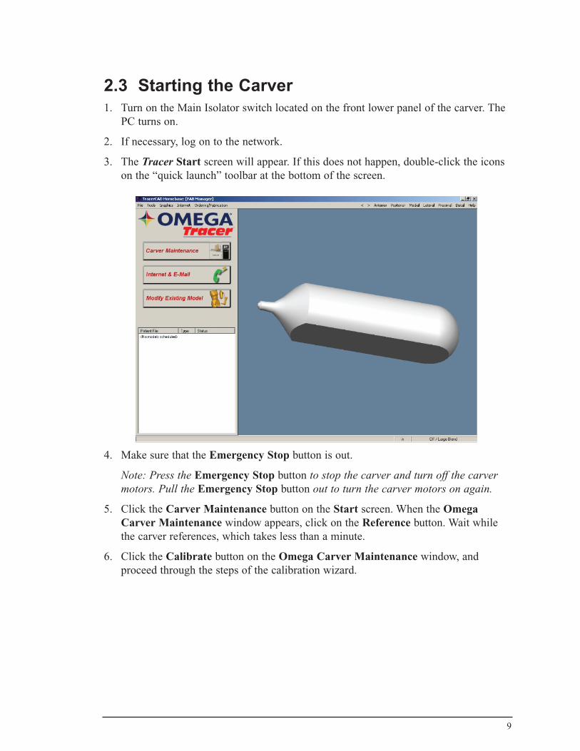
3. The Tracer Start screen will appear. If this does not happen, double-click the icons on the “quick launch” toolbar at the bottom of the screen.
4. Make sure that the Emergency Stop button is out.
Note: Press the Emergency Stop button to stop the carver and turn off the carver motors. Pull the Emergency Stop button out to turn the carver motors on again.
5. Click the Carver Maintenance button on the Start screen. When the Omega Carver Maintenance window appears, click on the Reference button. Wait while the carver references, which takes less than a minute.
6. Click the Calibrate button on the Omega Carver Maintenance window, and proceed through the steps of the calibration wizard.
10
2.4 Opening the Carver DoorThe carver door has been designed for one-handed use. Be careful not to trap or hit any body parts when opening or closing the enclosure. Take appropriate safety precautions to eliminate contact with dust in the enclosure. Wear suitable coveralls, a particulate mask, and safety goggles.
The carver door is electrically interlocked to protect the operator and ensure that the machine can only carve with the door closed. If the door is opened when the carver is cycling, the carver will stop.
To prevent foam dust off of the keyboard, make sure that the keyboard tray is pushed in before opening the carver door.
2.5 Shutting Down the Carver1. Shut down the software applications and PC in a safe manner.
2. Push the Emergency Stop button.
2. Turn off the Main Isolator switch and secure if necessary.
1111
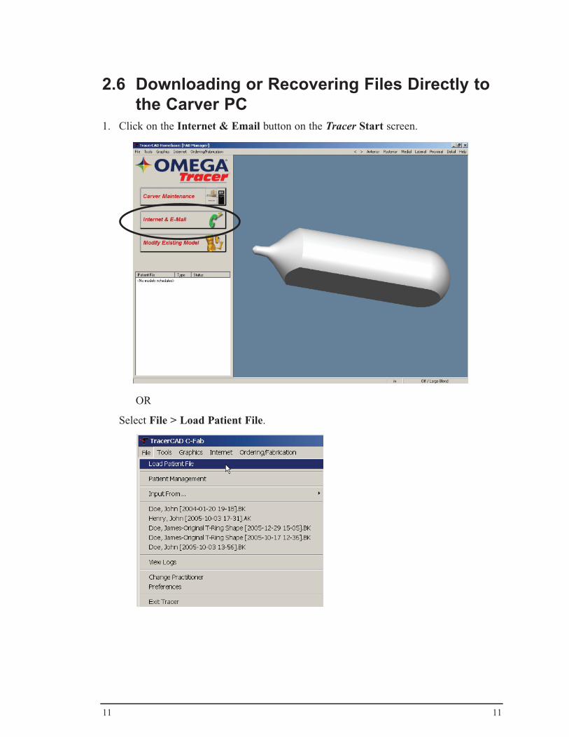
2.6 Downloading or Recovering Files Directly to the Carver PC
1. Click on the Internet & Email button on the Tracer Start screen.
OR
Select File > Load Patient File.
12
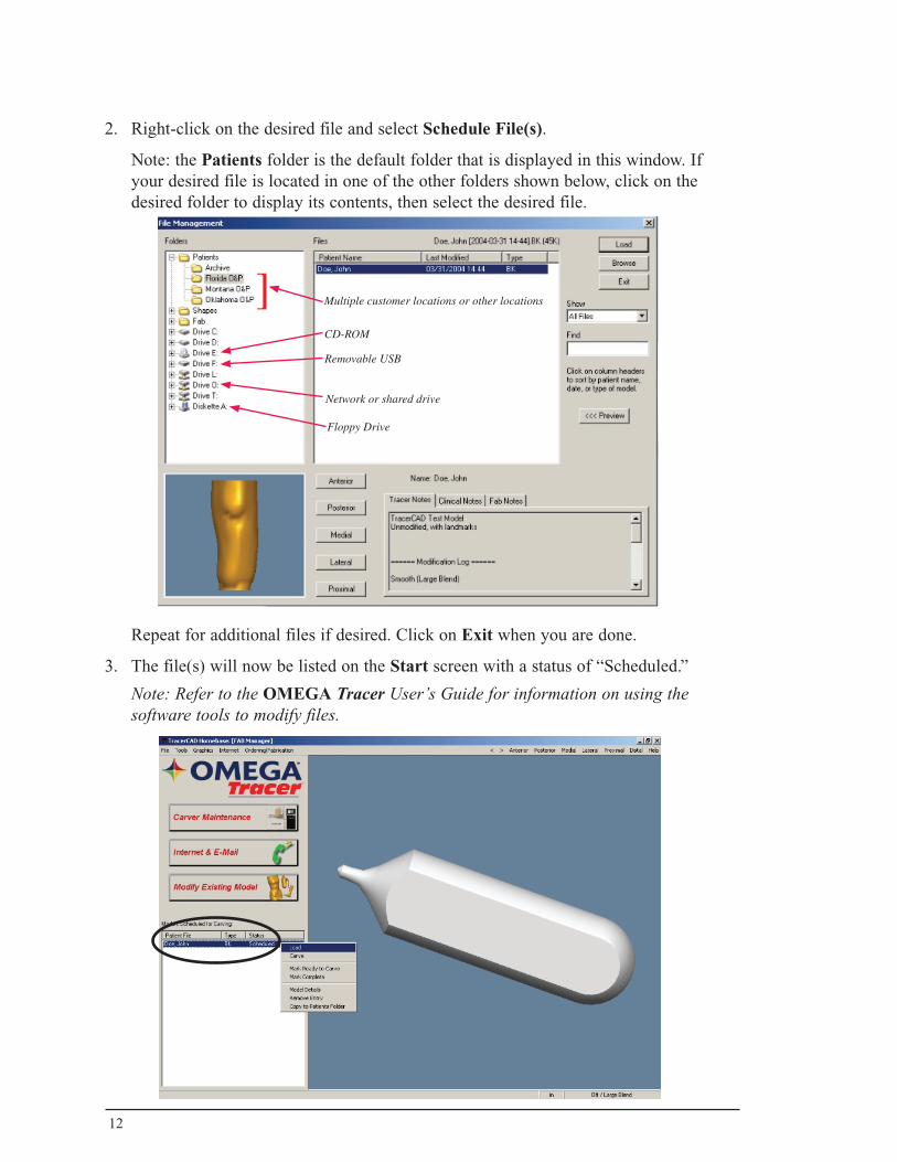
2. Right-click on the desired file and select Schedule File(s).
Note: the Patients folder is the default folder that is displayed in this window. If your desired file is located in one of the other folders shown below, click on the desired folder to display its contents, then select the desired file.
Repeat for additional files if desired. Click on Exit when you are done.
3. The file(s) will now be listed on the Start screen with a status of “Scheduled.”
Note: Refer to the OMEGA Tracer User’s Guide for information on using the software tools to modify files.
]Removable USB
Network or shared drive
Floppy Drive
Multiple customer locations or other locations
CD-ROM
13
3. CarvinG
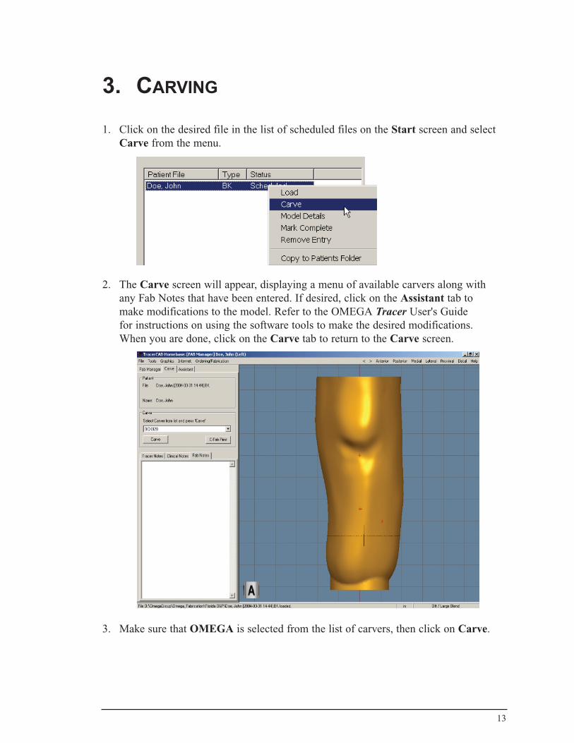
1. Click on the desired file in the list of scheduled files on the Start screen and select Carve from the menu.
2. The Carve screen will appear, displaying a menu of available carvers along with any Fab Notes that have been entered. If desired, click on the Assistant tab to make modifications to the model. Refer to the OMEGA Tracer User's Guide for instructions on using the software tools to make the desired modifications. When you are done, click on the Carve tab to return to the Carve screen.
3. Make sure that OMEGA is selected from the list of carvers, then click on Carve.
14
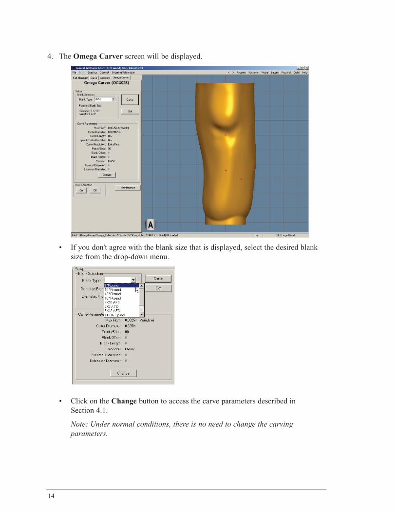
4. The Omega Carver screen will be displayed.
• If you don't agree with the blank size that is displayed, select the desired blank size from the drop-down menu.
• Click on the Change button to access the carve parameters described in Section 4.1.
Note: Under normal conditions, there is no need to change the carving parameters.
15
5. Load the blank into the carver as follows:
• Press the mandrel into the blank material to the shoulder of the mandrel.
Note: beware of any sharp points on the mandrel.
• Open the carver door.
• Using the Collet Wrench that is included with the carver, loosen the Collet Nut if needed (shown on page 5).
• Set the mandrel into the collet. Spin the foam blank until the slot on the bottom of the mandrel engages with the pin at the bottom of the collet.
• Tighten the Collet Nut with the Collet Wrench.
• Close the carver door.
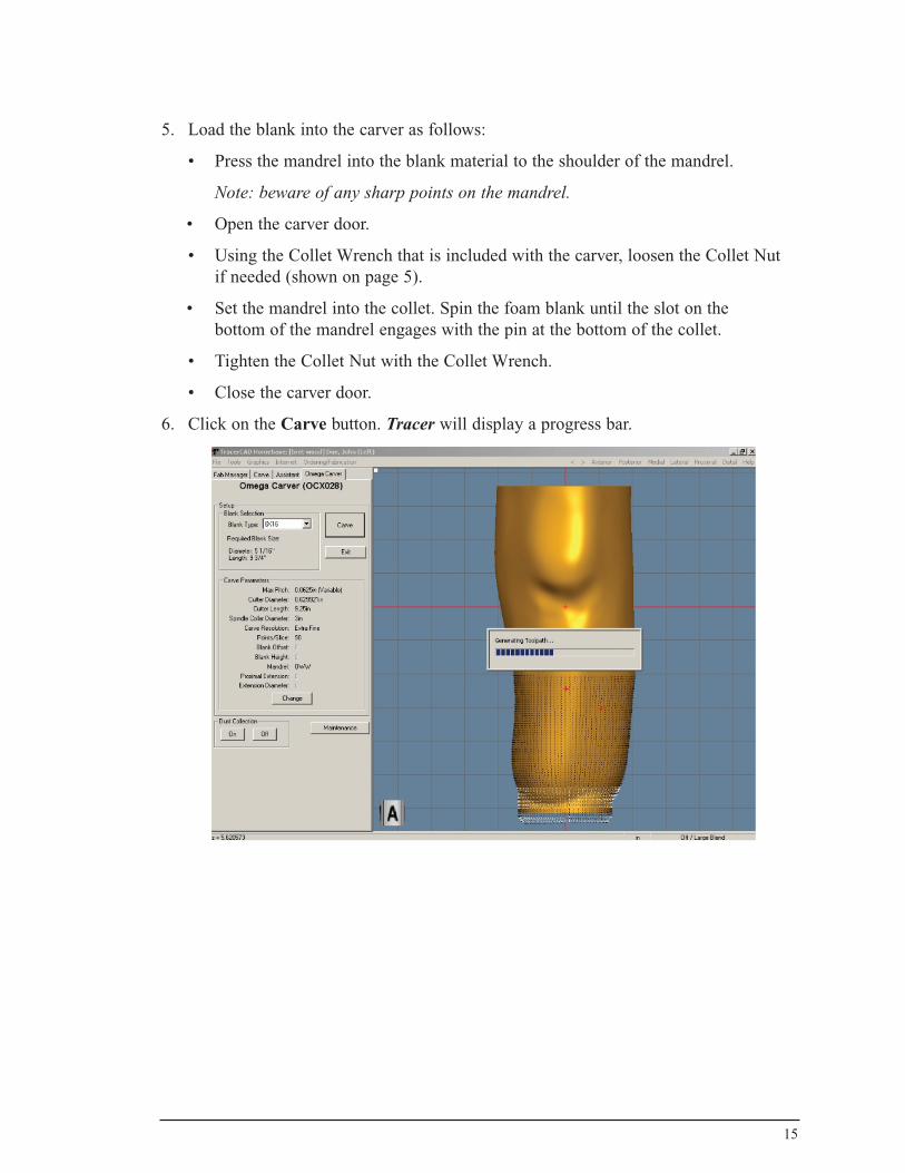
6. Click on the Carve button. Tracer will display a progress bar.
16
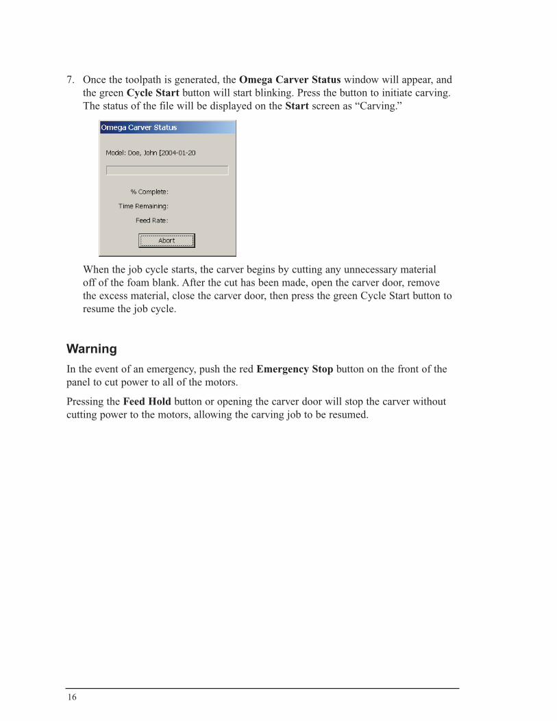
7. Once the toolpath is generated, the Omega Carver Status window will appear, and the green Cycle Start button will start blinking. Press the button to initiate carving. The status of the file will be displayed on the Start screen as “Carving.”
When the job cycle starts, the carver begins by cutting any unnecessary material off of the foam blank. After the cut has been made, open the carver door, remove the excess material, close the carver door, then press the green Cycle Start button to resume the job cycle.
Warning In the event of an emergency, push the red Emergency Stop button on the front of the panel to cut power to all of the motors.
Pressing the Feed Hold button or opening the carver door will stop the carver without cutting power to the motors, allowing the carving job to be resumed.
17
While the Carver is Running:
Opening the Carver Door
Opening the carver door will stop the carver without cutting power to the motors. The green Cycle Start button will start to blink after the door is opened. Press the button to resume carving.
Pressing the Feed Hold Button
Pressing the Feed Hold button will stop the carver without cutting power to the motors. The green Cycle Start button will start to blink after the door is opened. Press the button to resume carving.
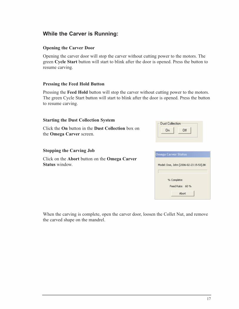
Starting the Dust Collection System
Click the On button in the Dust Collection box on the Omega Carver screen.
Stopping the Carving Job
Click on the Abort button on the Omega Carver Status window.
When the carving is complete, open the carver door, loosen the Collet Nut, and remove the carved shape on the mandrel.
18
Carving Additional Files
The ability to load other files while a file is currently being carved allows the files to be “prepared” for carving. (For example, a distal adapter can be added.) When the current file is complete, the new file can be started with out the delay of placing the adapter on the model.
To load additional files while another model is still carving:
1. Click on the desired file in the list of scheduled files on the Start screen and select Mark Ready to Carve from the menu.
2. The Carve screen will appear, displaying a menu of available carvers along with any Fab Notes that have been entered. If desired, click on the Assistant tab to make modifications to the model. Refer to the OMEGA Tracer User's Guide for instructions on using the software tools to make the desired modifications. When you are done, click on the Carve tab to return to the Carve screen.
3. Make sure that OMEGA is selected from the list of carvers, then click on Carve.
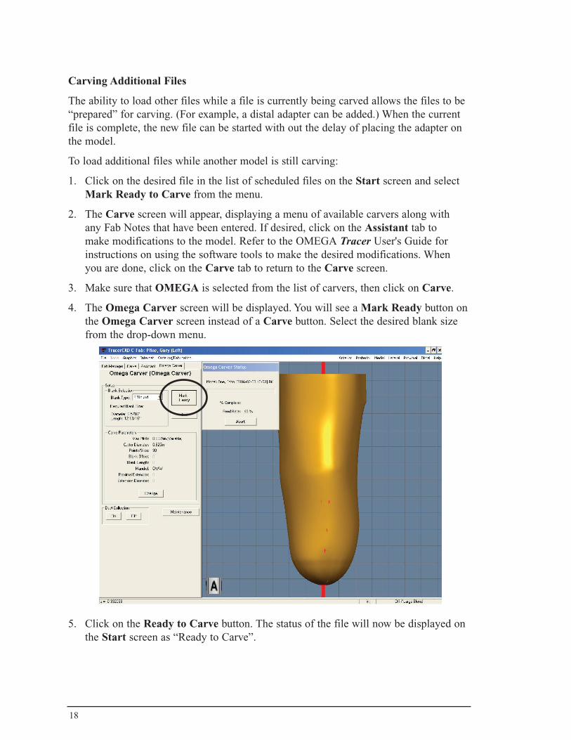
4. The Omega Carver screen will be displayed. You will see a Mark Ready button on the Omega Carver screen instead of a Carve button. Select the desired blank size from the drop-down menu.
5. Click on the Ready to Carve button. The status of the file will now be displayed on the Start screen as “Ready to Carve”.
19
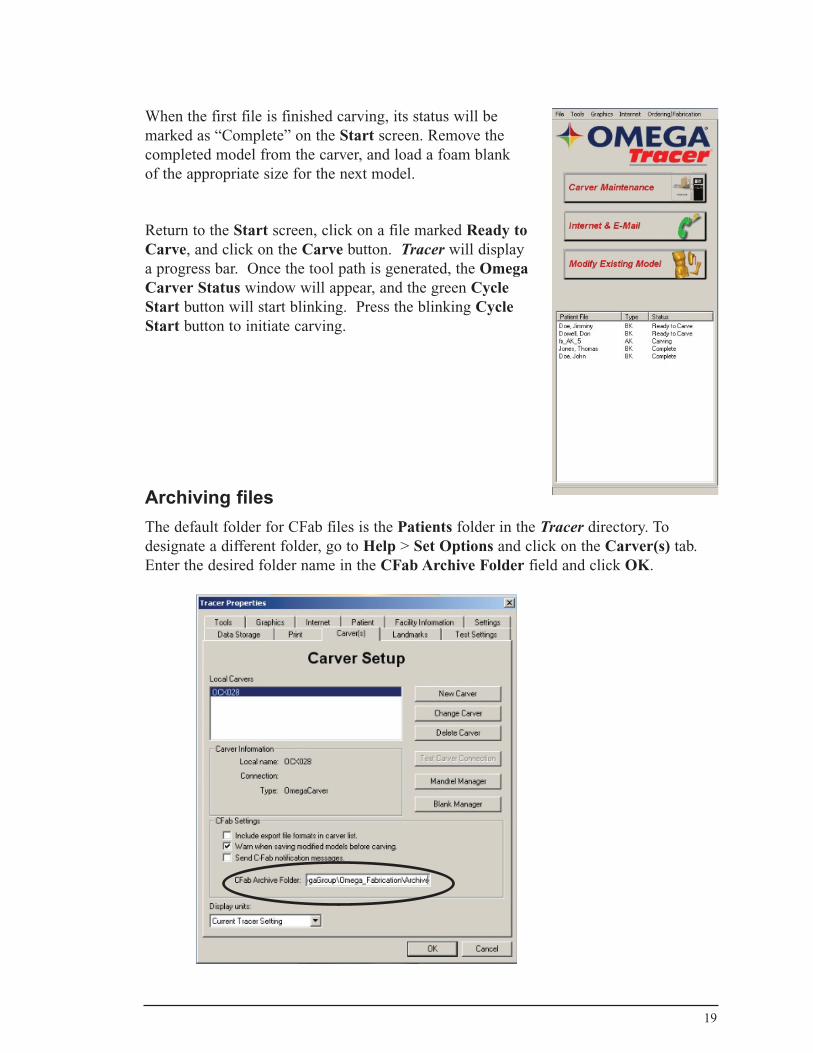
When the first file is finished carving, its status will be marked as “Complete” on the Start screen. Remove the completed model from the carver, and load a foam blank of the appropriate size for the next model.
Return to the Start screen, click on a file marked Ready to Carve, and click on the Carve button. Tracer will display a progress bar. Once the tool path is generated, the Omega Carver Status window will appear, and the green Cycle Start button will start blinking. Press the blinking Cycle Start button to initiate carving.
Archiving filesThe default folder for CFab files is the Patients folder in the Tracer directory. To designate a different folder, go to Help > Set Options and click on the Carver(s) tab. Enter the desired folder name in the CFab Archive Folder field and click OK.
20
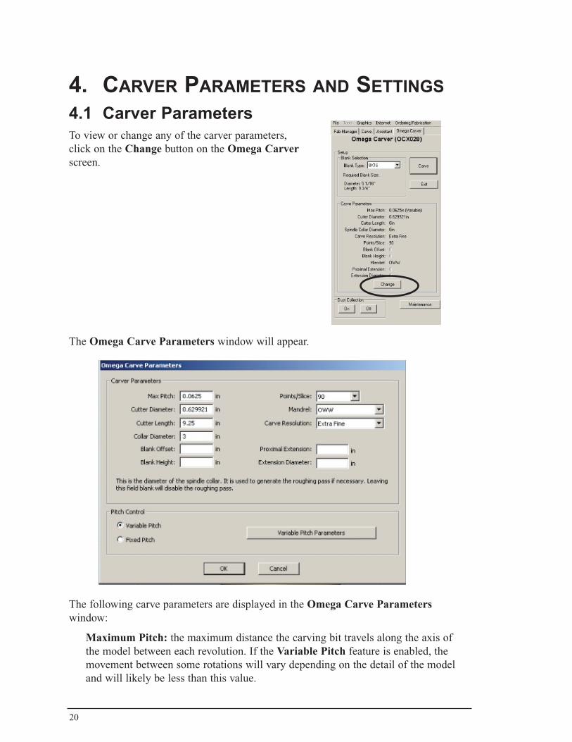
4. CarverparametersandsettinGs4.1 Carver ParametersTo view or change any of the carver parameters, click on the Change button on the Omega Carver screen.
The Omega Carve Parameters window will appear.
The following carve parameters are displayed in the Omega Carve Parameters window:
Maximum Pitch: the maximum distance the carving bit travels along the axis of the model between each revolution. If the Variable Pitch feature is enabled, the movement between some rotations will vary depending on the detail of the model and will likely be less than this value.
21
Cutter Diameter: the diameter of the carver bit. Tracer expects a round cutter. It is important to set this accurately since this value is used to compensate for the diameter of the cutter when carving models.
Blank Offset: shifts the model proximally in the blank (away from the chuck). This option is typically used when the mandrel might interfere with the carving. Tracer remembers the setting for each model type (this is particularly useful for AFOs). Note that the blank must be long enough with this value added to carve the model.
Blank Length: carves the model at the most proximal end of a blank of this length.
Note: Only one Blank Offset or Blank Length is allowed.
Cutter Length: the exposed length of the cutter. Enter 9 1/4" for this setting.
Collet Diameter: Enter 3" for this setting.
Points/Slice: the number of data points to be sent to the carver for every revolution (slice) of the model. Only 90 points/slice and 180 points/slice are supported. Usually 90 is sufficient and recommended.
Mandrel: Make sure that OWW is selected as the mandrel. The OMEGA Carver is designed to work only with the OWW mandrel.
Proximal Extension: the amount (if any) that you would like to carve beyond the proximal end of the model.
Proximal Diameter: allows you to expand the diameter of the proximal extension by the amount specified. This is useful for providing a smooth surface that tapers away from the model when vacu-forming over the carved model.
Variable Pitch: Tracer incorporates a technology that analyzes the model and adjusts the pitch for the smoothest finish possible. Select this option to use a Variable Pitch, which is the setting that is recommended by Ohio Willow Wood for most applications. To change the variable pitch parameters, click on the Variable Pitch Parameters button. Under normal circumstances these parameters do not need to be changed; they should only be changed under the guidance of OMEGA Tracer Technical support
Fixed Pitch: Select this option to disable Variable Pitch and use a pitch equal to the maximum pitch setting. This setting is only recommended for models that are not sensitive to the “grooving” created during the carving process.
22
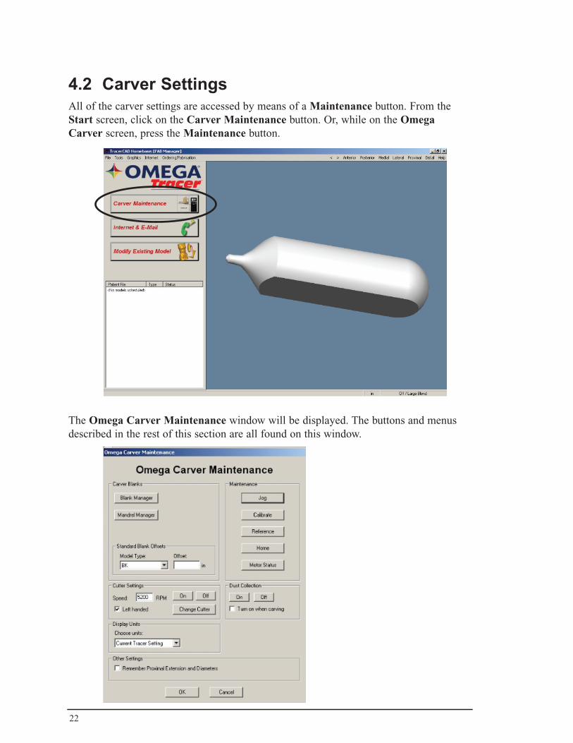
4.2 Carver SettingsAll of the carver settings are accessed by means of a Maintenance button. From the Start screen, click on the Carver Maintenance button. Or, while on the Omega Carver screen, press the Maintenance button.
The Omega Carver Maintenance window will be displayed. The buttons and menus described in the rest of this section are all found on this window.
23
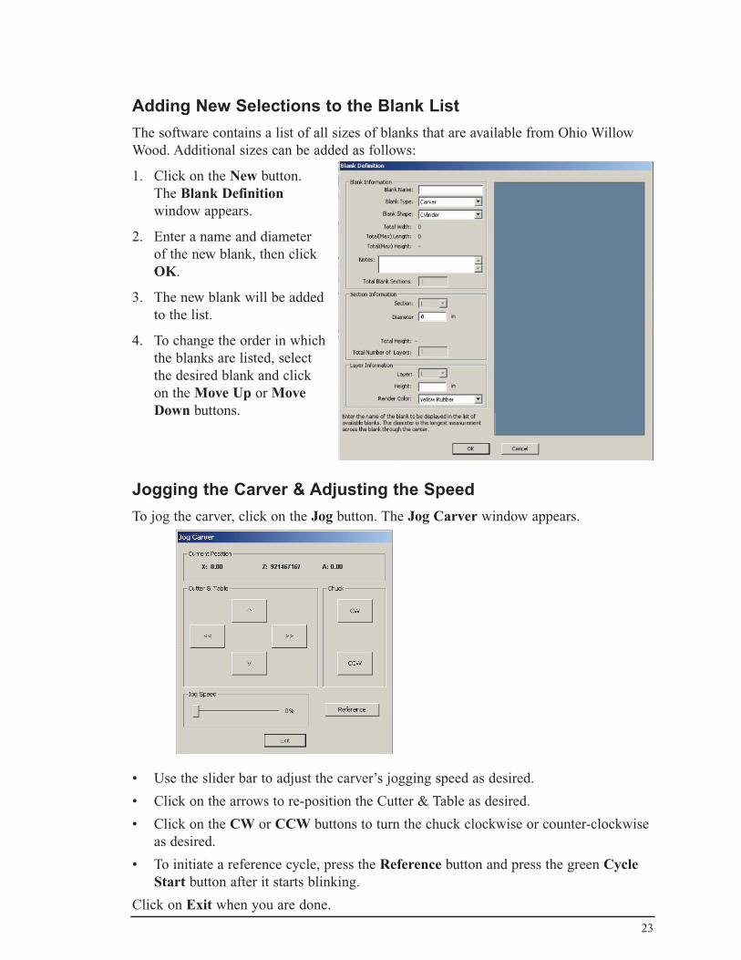
Adding New Selections to the Blank ListThe software contains a list of all sizes of blanks that are available from Ohio Willow Wood. Additional sizes can be added as follows:
1. Click on the New button. The Blank Definition window appears.
2. Enter a name and diameter of the new blank, then click OK.
3. The new blank will be added to the list.
4. To change the order in which the blanks are listed, select the desired blank and click on the Move Up or Move Down buttons.
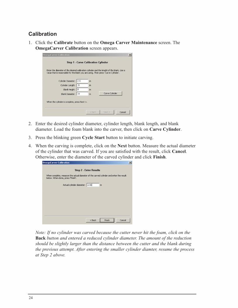
Jogging the Carver & Adjusting the SpeedTo jog the carver, click on the Jog button. The Jog Carver window appears.
• Use the slider bar to adjust the carver’s jogging speed as desired.
• Click on the arrows to re-position the Cutter & Table as desired.
• Click on the CW or CCW buttons to turn the chuck clockwise or counter-clockwise as desired.
• To initiate a reference cycle, press the Reference button and press the green Cycle Start button after it starts blinking.
Click on Exit when you are done.
24
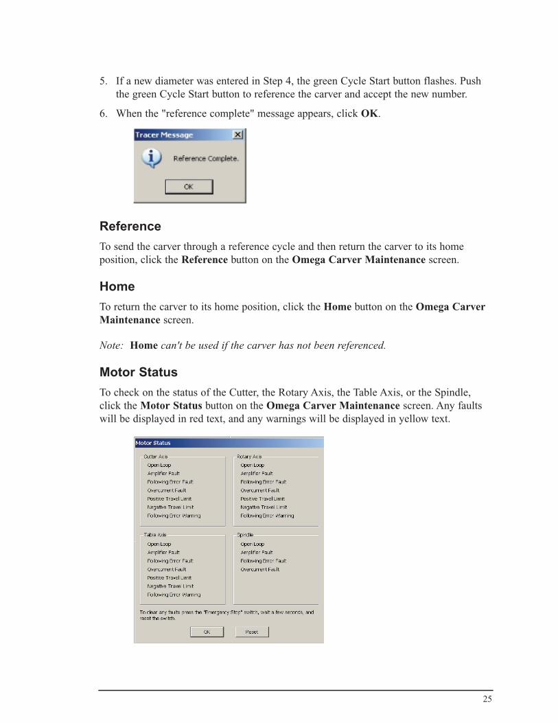
Calibration1. Click the Calibrate button on the Omega Carver Maintenance screen. The
OmegaCarver Calibration screen appears.
2. Enter the desired cylinder diameter, cylinder length, blank length, and blank diameter. Load the foam blank into the carver, then click on Carve Cylinder.
3. Press the blinking green Cycle Start button to initiate carving.
4. When the carving is complete, click on the Next button. Measure the actual diameter of the cylinder that was carved. If you are satisfied with the result, click Cancel. Otherwise, enter the diameter of the carved cylinder and click Finish.
Note: If no cylinder was carved because the cutter never hit the foam, click on the Back button and entered a reduced cylinder diameter. The amount of the reduction should be slightly larger than the distance between the cutter and the blank during the previous attempt. After entering the smaller cylinder diamter, resume the process at Step 2 above.
25
5. If a new diameter was entered in Step 4, the green Cycle Start button flashes. Push the green Cycle Start button to reference the carver and accept the new number.
6. When the "reference complete" message appears, click OK.
ReferenceTo send the carver through a reference cycle and then return the carver to its home position, click the Reference button on the Omega Carver Maintenance screen.
HomeTo return the carver to its home position, click the Home button on the Omega Carver Maintenance screen.
Note: Home can't be used if the carver has not been referenced.
Motor StatusTo check on the status of the Cutter, the Rotary Axis, the Table Axis, or the Spindle, click the Motor Status button on the Omega Carver Maintenance screen. Any faults will be displayed in red text, and any warnings will be displayed in yellow text.
26
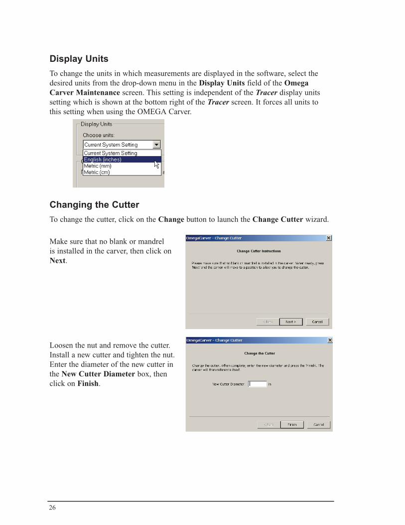
Display UnitsTo change the units in which measurements are displayed in the software, select the desired units from the drop-down menu in the Display Units field of the Omega Carver Maintenance screen. This setting is independent of the Tracer display units setting which is shown at the bottom right of the Tracer screen. It forces all units to this setting when using the OMEGA Carver.
Changing the CutterTo change the cutter, click on the Change button to launch the Change Cutter wizard.
Make sure that no blank or mandrel is installed in the carver, then click on Next.
Loosen the nut and remove the cutter. Install a new cutter and tighten the nut. Enter the diameter of the new cutter in the New Cutter Diameter box, then click on Finish.

27
Dust CollectionClick the On button to turn on the Dust Collection function; click the Off button to turn the funtion off.
Placing a check in the Turn on when carving box will cause the Dust Collection system to turn on automatically each time a carving job is started. Once the system is started automatically, it will continue to run until it is turned off using the Off button on this screen or on the Omega Carver Maintenance screen.
Remember Proximal Extension and Diameter
Place a check in this box on the Omega Carver Maintenance screen if you would like the carver to remember the proximal extension and diameter that you enter in the Omega Carve Parameters screen (refer to Section 4.1). These values are remembered on a per-model basis.
28
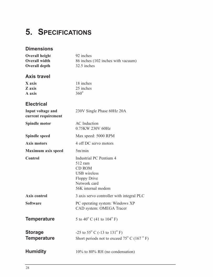
5. speCifiCations
Dimensions Overall height 92 inchesOverall width 86 inches (102 inches with vacuum)Overall depth 32.5 inches
Axis travel X axis 18 inchesZ axis 25 inchesA axis 360o
Electrical Input voltage and 230V Single Phase 60Hz 20Acurrent requirement
Spindle motor AC Induction 0.75KW 230V 60Hz
Spindle speed Max speed: 5000 RPM
Axis motors 4 off DC servo motors
Maximum axis speed 5m/min
Control Industrial PC Pentium 4 512 ram CD ROM USB wireless Floppy Drive Network card 56K internal modem
Axis control 3 axis servo controller with integral PLC
Software PC operating system: Windows XP CAD system: OMEGA Tracer
Temperature 5 to 40o C (41 to 104o F)
Storage -25 to 55o C (-13 to 131o F)
Temperature Short periods not to exceed 75o C (167 o F)
Humidity 10% to 80% RH (no condensation)
29
6. safetyPlease read and fully understand this instruction manual before using the carver. Be sure to understand all safety precautions and warnings prior to operation and maintenance. Operation and servicing of automated equipment involves potential hazards and it is important that you take precautions to avoid injury.
• Ohio Willow Wood cannot anticipate all possible circumstances that might involve a potential hazard. The warnings listed in this manual therefore do not necessarily cover all circumstances.
• If a procedure, tool, work method, material, or operating technique not specifically recommended by Ohio Willow Wood is used, make that such a procedure does not endanger yourself and others.
• Observe all federal, state, and local regulations, as well as your employer’s health and safety practices, when operating the carver.
• If English is not read and understood by any carver operators, display safety precautions and warnings in their native language(s) on the carver.
• Ohio Willow Wood will not be held responsible for any incidental or consequential damages or other costs resulting from abuse or misapplication of the carver.
• Keep hands clear of moving machinery. Loose fitting clothing, jewelry, hair or ties may become entangled in the machinery. Do not wear these items while operating or servicing the machine.
• Electric shocks can kill. The carver control enclosure should only be opened by competent service personnel. The carver control enclosure should never be powered up with the protective covers removed.
• The carver is intended for use in a variety of countries using different supply voltages. The carver is set up for use on one particular supply voltage. The machine identity label on the back of the carver clearly shows which supply voltage is required.
• The carver has been fitted with various devices in order to protect against any short-circuit or overload conditions.
• Do not remove, disable, or bypass the various safety and protection devices (guards and safety door etc.) fitted for the safety of the operator.
• Always unplug the carver's power cord before performing maintenance of any kind.
• Never modify the machine without prior written permission of Ohio Willow Wood. If modification of the machine has been made without permission, including removal or stopping functions of protective devices, Ohio Willow Wood accepts no liability whatsoever.

30
• During operation of the carver, the following items should be strictly observed to avoid a generation of unexpected fire:
1. Do not machine flammable material.
2. Do not place flammable articles around the machine.
3. If the machine is smoking or smells of smoke or burning, immediately stop the machine. Shut the carver down in a controlled manner and isolate the power. Do not use again until the cause has been located and removed.
• Avoid cutting excessively hard materials e.g. hard wood and/or preventing the machine spindle to move as this may damage the machine.
• Ohio Willow Wood recommends using suitable and sufficient extraction while operating the carver. Dispose of extracted waste in accordance with your local authority regulations.
31
7. maintenanCe
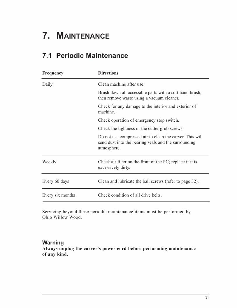
7.1 Periodic Maintenance
Frequency Directions
Daily Clean machine after use.
Brush down all accessible parts with a soft hand brush, then remove waste using a vacuum cleaner.
Check for any damage to the interior and exterior of machine.
Check operation of emergency stop switch.
Check the tightness of the cutter grub screws.
Do not use compressed air to clean the carver. This will send dust into the bearing seals and the surrounding atmosphere.
Weekly Check air filter on the front of the PC; replace if it is excessively dirty.
Every 60 days Clean and lubricate the ball screws (refer to page 32).
Every six months Check condition of all drive belts.
Servicing beyond these periodic maintenance items must be performed by Ohio Willow Wood.
WarningAlways unplug the carver's power cord before performing maintenance of any kind.
32
7.2 Cleaning and Lubricating the Ball ScrewsIn order to keep the ball screws dust-free and properly lubricated, this procedure must be performed at least once every 60 days.
Items required:
• A general-purpose, graphite-free lubricant such as Mobil Vactra Oil No.2
• Rubbing alcohol
• Towels
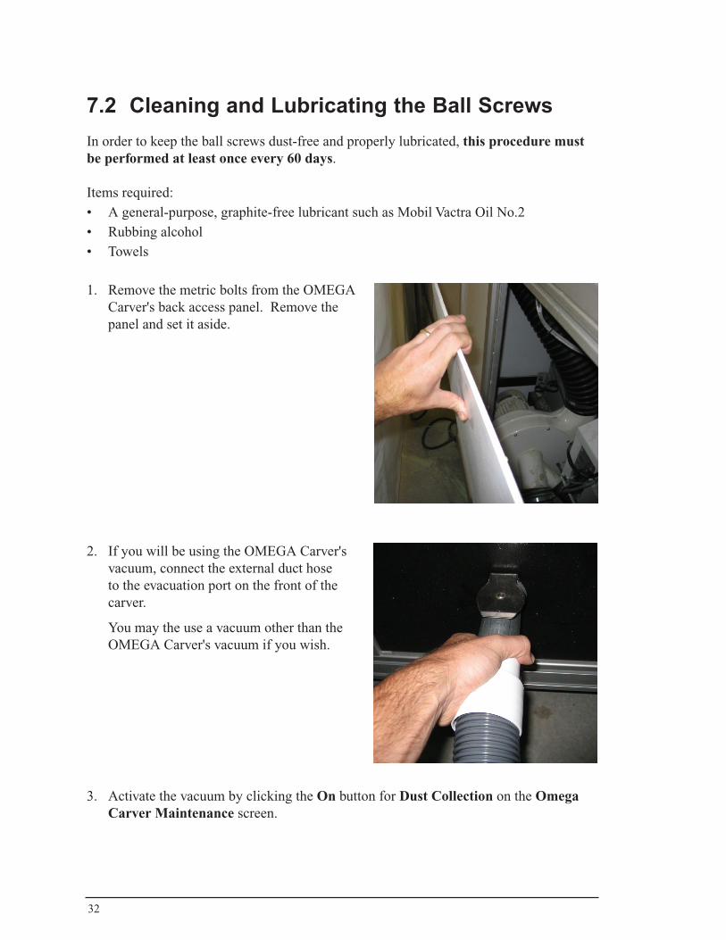
1. Remove the metric bolts from the OMEGA Carver's back access panel. Remove the panel and set it aside.
2. If you will be using the OMEGA Carver's vacuum, connect the external duct hose to the evacuation port on the front of the carver.
You may the use a vacuum other than the OMEGA Carver's vacuum if you wish.
3. Activate the vacuum by clicking the On button for Dust Collection on the Omega Carver Maintenance screen.
33
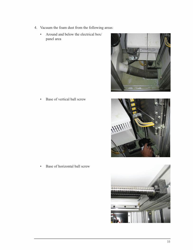
4. Vacuum the foam dust from the following areas:
• Around and below the electrical box/panel area
• Base of vertical ball screw
• Base of horizontal ball screw
34
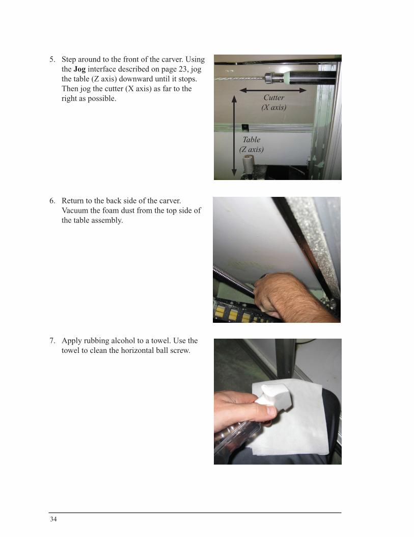
5. Step around to the front of the carver. Using the Jog interface described on page 23, jog the table (Z axis) downward until it stops. Then jog the cutter (X axis) as far to the right as possible.
6. Return to the back side of the carver. Vacuum the foam dust from the top side of the table assembly.
7. Apply rubbing alcohol to a towel. Use the towel to clean the horizontal ball screw.
Cutter (X axis)
Table(Z axis)
35
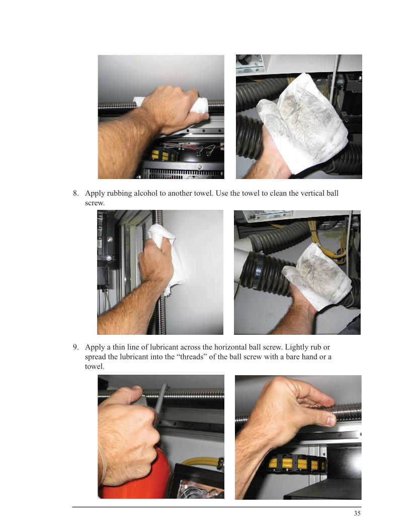
8. Apply rubbing alcohol to another towel. Use the towel to clean the vertical ball screw.
9. Apply a thin line of lubricant across the horizontal ball screw. Lightly rub or spread the lubricant into the “threads” of the ball screw with a bare hand or a towel.
36
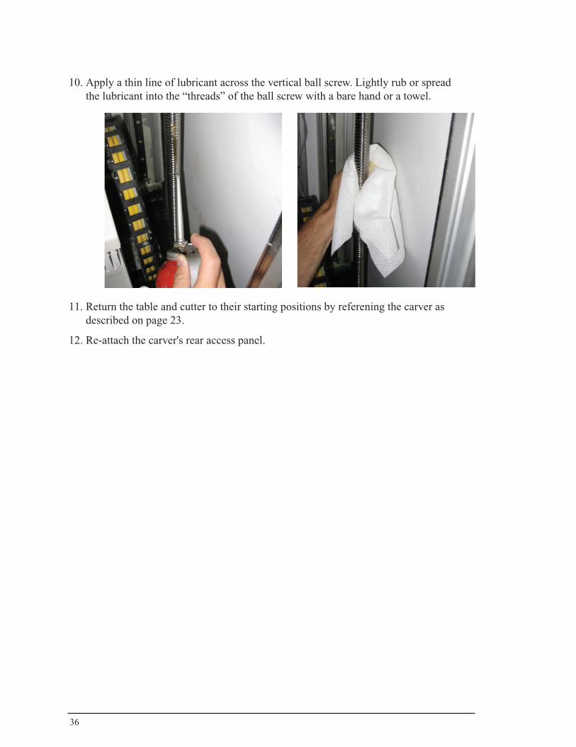
10. Apply a thin line of lubricant across the vertical ball screw. Lightly rub or spread the lubricant into the “threads” of the ball screw with a bare hand or a towel.
11. Return the table and cutter to their starting positions by referening the carver as described on page 23.
12. Re-attach the carver's rear access panel.
37
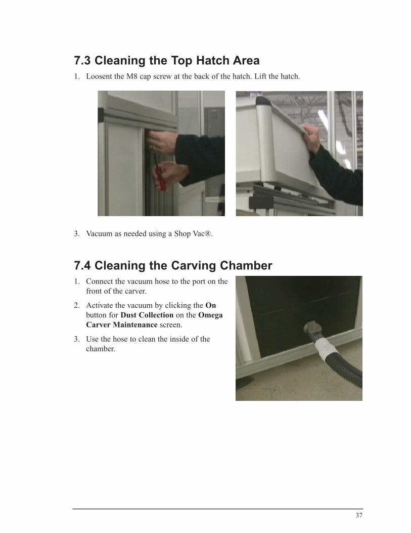
7.3 Cleaning the Top Hatch Area1. Loosent the M8 cap screw at the back of the hatch. Lift the hatch.
3. Vacuum as needed using a Shop Vac®.
7.4 Cleaning the Carving Chamber1. Connect the vacuum hose to the port on the
front of the carver.
2. Activate the vacuum by clicking the On button for Dust Collection on the Omega Carver Maintenance screen.
3. Use the hose to clean the inside of the chamber.
38
7.5 Panel Cleaning
Cleaning the clear panels
1. Soften dirt by wiping with lukewarm water.
2. Gently remove dirt with a sponge or soft cloth and a solution of lukewarm water and ordinary household cleaner or mild soap.
3. Repeat the cleaning process, then dry the panel with a soft cloth.
Notes: • Do not scrub clear panels with brushes or instruments.• Avoid contacting the surface with Butyl Cellosolve, Isopropanol, or any other
solvents.• Avoid any abrasives or cleaners of a highly alkaline nature.• Test any cleaner on a small area of the carver prior to use.• Solvent cleaners which state they are suitable for use on polycarbonates may not be
safe for use on the clear panels.
Cleaning the white panels
1. To remove dust, wipe in one direction with a solution of soap and water. Note: wiping in a circular motion can create a build-up of static charge.
2. Remove any residual soapy film with a lint-free wipe moistened with heptane, octane, methyl alcohol, or methylated sprits. These solvents will also remove greasy deposits and dust or dirt adhering to the surface. Take appropriate safety measures when using any of these cleaning agents.

39
7.6 Cleaning the Dust Collection Filter Turn the handle on the top of the to rotate the cleaning flapper inside the canister. This will shake the dust from the filter and allow it to fall into the collection bag.
7.7 Replacing the Dust Collection Bag Note: Wearing a particle mask/respirator for protection against fine dust particles during cleaning is highly recommended.
1. Remove the Collector Bag by pushing the Snap Ring of the Collection Bag upwards at an angle and pulling the Collection Bag and Snap Ring out.
2. Empty the contents into an appropriate container.
3. Place the Snap Ring over the top of the new Collection Bag and fold over the bag approximately three inches.
4. Insert the Snap Ring of the Collection Bag into the bottom of the housing at an angle.
5. Pull down on the Snap Ring to make sure it “seats” in the housing.
Note: make sure the Snap Ring “snaps” into place in the housing, and also that the Collection Bag hangs down approximately 3" so that there are no air leaks.
7.8 Replacement Parts
FB-001 Carver MandrelFB-003 Spinal MandrelOMEGA-5237 Carver Cutting BitOMEGA-3610 Metal Shielded Collection Bags (Set of 5)

40
8. trouBleshootinG
The OMEGA Carver Will Not Reference
Definition:
The green button will not stop flashing when the operator attempts to reference the OMEGA Carver.
Likely cause(s):
1. One of the safety eyes (proximity switches) either inside the door or underneath the top hatch is not making contact with the metal safety brackets. There may be a build-up of foam dust between the bracket and the proximity switch.
2. The startup procedure has not been done in the correct sequence.
3. One of the Axis motors may be unresponsive because an amplifier may have failed on the GEO Brick (motor controller). The cutter assembly will move but the Table/Chuck assembly will not travel in any direction.
4. The power cord on the GEO brick has come loose, or is not completely making contact.
5. The Config file that was originally flashed into the controller has become corrupted.
Solution:
1. Press in the Emergency stop button, abort the reference sequence by clicking on abort, open the carving door, and then shut the door. Verify that the door is tightly latched shut. Pull the emergency button back out. Attempt to reference the OMEGA Carver again.
2. Always verify that the OMEGA Carver's front door is always closed during the start-up procedure. This will insure that there is a constant connection between the four safety eyes.
3. One of the safety eyes could be malfunctioning. In that circumstance the operator should contact OMEGA Tracer support.
4. Attempt to jog the OMEGA Carver. The operator should immediately contact OMEGA Tracer support if the Table/Chuck assembly will not travel in anydirection.
5. If reconfiguring the OMEGA Carver’s GEO Brick is necessary, contact OMEGA Tracer support.
41
Motor Fault
Definition:
One of the OMEGA Carver’s servo motors is being "taxed" or is attempting to move past the specified limits.
Likely cause(s):
1. The Axis motor did not receive enough power to activate the motor.
2. There was an error in the positioning of the motor, or was not phased properly.
3. A new cutter was installed or the cutter was rotated by hand.
4. There was an amplifier fault on the GEO Brick controller.
5. The “chuck” was over-tightened.
6. The settings that control the rotation of the chuck, the motion of the spindle assembly, and the table are set too low (or too high) and need to be adjusted.
7. Dust particles have collected within the spindle axis motor's or the table axis motor's housings, and the dust buildup is binding up the motor. In this specific case you may actually hear a "knocking" or "clunking" sound when the table or spindle axis attempts to move.
Solution:
1. Press the Emergency stop button and then release the Emergency Stop Button. Attempt to reference or carve the shape file again.
2. Press the Emergency stop button and then release the Emergency Stop Button.Click the "reset" button in the motor status panel. The errors on screen should then go away. Attempt to Reference the carver or "jog" the machine's axis again. If an "amplifier" error appears or does not clear (located in the motor status panel), than it is likely that an amplifier on the GEO brick has failed. This can be verified by looking directly at the GEO brick to identify the error code that might be flashing.
3. If the motor fault is occurring randomly during the carving phase, then it is very likely that the GEO brick parameters need to be changed or edited. Please contact OMEGA Tracer support.
4. Clean and lubricate the ball screws (refer to page 32).

42
Carved Shape (Foam Model) Measurements Are Incorrect
Definition:
The circumference of the shape that is outputted by the OMEGA Carver is too small or too large, or the shape is deformed in some manner.
Likely cause(s):
1. The cutting bit could be loose or may have traveled out.
2. The mandrel may not have been secured tightly.
3. The OMEGA Carver may be out of calibration.
4. A software error could have occurred.
Solution:
1. Verify that the cutter is firmly in the spindle housing and that the collet ring is tightened.
2. Verify that the mandrel is inserted properly and tightened. Remember that the OMEGA Carver mandrels are “keyed” to specifically fit the OMEGA Carver’s chuck.
3. Calibrate the carver and verify that the OMEGA Carver is indeed calibrated.
4. Insure that all the people who operate the OMEGA Carver are taking circumfer-ence measurements in the same way, and make sure that they are all using the same operational practices.
5. Always operate with most current version of the Tracer software.

43
The OMEGA Carver’s PC Will Not Boot Up
Definition:
The OMEGA Carver’s PC will not boot up. The PC does not make any sound, nor will the monitor power up, and all activity lights are off on the front of the PC.
Likely cause(s):
1. The power supply in the on-board PC has been hit with some type of power surge.
2. The Main Breaker has been “tripped” or the fuses have failed.
Solution:
1. Verify the power connections on the PC. Verify that the activity lights on the front of the PC chassis are lit when power is restored to the OMEGA Carver.
2. Verify that the four main breaker switches on the OMEGA Carver are powered on, and that the fuses under the block numbered FU221 are functional. Contact OMEGA Tracer support at this point for further instruction.
Carver Maintenance Button (Within Tracer) Is Inactive
Definition:
Tracer loads as it should and the initial screen looks normal. But when the operator clicks on the Carver Maintenance button, Tracer locks up or does not proceed.
Likely cause(s):
1. Tracer can not communicate with the GEO Brick controller via USB port be-cause of a driver mismatch or GEO Brick firmware corruption, or a general failure within the GEO Brick (motor controller).
Solution:
1. Go to Start > Control Panel > Performance and Maitenance > System. Click on the Hardware tab, then click on the Device Manager button. Check to see if 2.0 UMAC DELTA TAU DEVICE is listed under "Universal Serial Bus Controllers."
• If this device is not listed, then it is likely that the GEO brick is down, or that the USB connection has failed on the GEO brick. Verify that the GEO brick is running and has power.
• If this device is listed, this means that the firmware has been corrupted on the GEO brick. Contact OMEGA Tracer support for further instruction.
44
Spindle/Cutter Stops Suddenly While Carving a Model
Definition:
The Cutter spins and stops abruptly; green and amber lights briefly flash or continue to flash. Using the E-stop button doesn't clear the problem. The cutter continues to stop during the carving sequence (either in the initial cutoff, or while the model is being carved).
Likely cause(s):
1. There is likely a loose wire connection, at either the motor contactor (mounted directly next to the SOLA power supply) or the connection directly on the back of the E-Stop.
Solution:
1. Access the electrical panel and verify that two wire connections are secure.
The Red "Pause" Button Does Not Function or Will Not Pause/Stop the Carver From Running
Definition:
One of the two metal brackets is not making contact with the safety eyes (proximity switches).
Likely cause(s):
1. The OMEGA Carver has redundant safety eye switches (two separate sets of two switches). If all four of these safety eyes are not making contact with metal (at either the door bracket or the top hatch bracket), the red "pause" button will not function. It will light up and flash, but when it will not work when pressed.
2. This could also cause the OMEGA Carver’s cutter to stop while the rest of the machine continues to run. This could be destructive to the OMEGA Carver’s hardware.
Solution:
1. While the OMEGA Carver is powered on, remove the access panel from the back of the carver. Check to see if all four of the safety eye switches are lit up. (One set is directly in front of you when you are standing at the back of the carver; the other set is located just to the right hand side of the PC casing, where the frame of the carver meets the framing of the top half of the carving chamber.) If one of these safety eyes is not lit up, then you will need to manually turn it until it lights up.
Note: it may also be necessary to adjust the metal bracket in the top hatch.

45
The "Chuck" Continues To Spin During the Reference Sequence
Definition:
The proximity switch underneath the chuck/table is not making contact.
Likely cause(s):
1. The cable link or proximity switch is loose.
Solution:
1. Jog the table axis all the way up until it stops.
2. Find the gray or yellow cable connection that connects to the chuck assembly (underneath the table).
3. Verify that the proximity switch is lit.
4. Turn the cable clockwise to ensure that it is tight and that it is making contact with the sensor.
5. Clean out the area and the sensor with compressed air. It is possible that a buildup of dust is causing the problem.
6. Jog the chuck clockwise (CW), then counter-clockwise (CCW). Then reference the carver again.
46
9. tipsformakinGsoCketsoverfoam
Socket Type
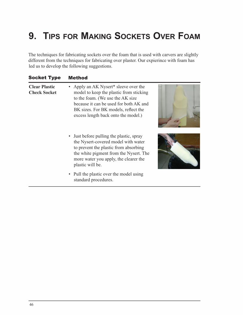
• Apply an AK Nysert* sleeve over the model to keep the plastic from sticking to the foam. (We use the AK size because it can be used for both AK and BK sizes. For BK models, reflect the excess length back onto the model.)
• Just before pulling the plastic, spray the Nysert-covered model with water to prevent the plastic from absorbing the white pigment from the Nysert. The more water you apply, the clearer the plastic will be.
• Pull the plastic over the model using standard procedures.
Clear Plastic Check Socket
Method
The techniques for fabricating sockets over the foam that is used with carvers are slightly different from the techniques for fabricating over plaster. Our expierince with foam has led us to develop the following suggestions.
47
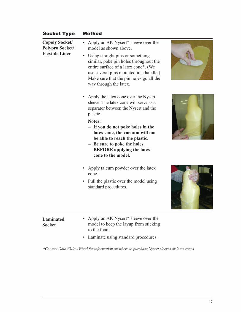
• Apply an AK Nysert* sleeve over the model as shown above.
• Using straight pins or something similar, poke pin holes throughout the entire surface of a latex cone*. (We use several pins mounted in a handle.) Make sure that the pin holes go all the way through the latex.
• Apply the latex cone over the Nysert sleeve. The latex cone will serve as a separator between the Nysert and the plastic.
Notes: – If you do not poke holes in the
latex cone, the vacuum will not be able to reach the plastic.
– Be sure to poke the holes BEFORE applying the latex cone to the model.
• Apply talcum powder over the latex cone.
• Pull the plastic over the model using standard procedures.
Copoly Socket/ Polypro Socket/Flexible Liner
Laminated Socket
• Apply an AK Nysert* sleeve over the model to keep the layup from sticking to the foam.
• Laminate using standard procedures.
*Contact Ohio Willow Wood for information on where to purchase Nysert sleeves or latex cones.
Socket Type Method

48
IndexAAbort 17Adjusting the Speed 23Archive Folder 19axis motors 28axis speed 28axis travel 28A axis 5
Bball screws 32blank 15Blank Definition 23Blank Length 21Blank Offset 21
Ccarving 13C-Fab 5Calibration 24Carver Maintenance button 22Carver Mandrel 39Carver Parameters 20Carver Settings 22Carve button 15Carve Cylinder 24Carve screen 13, 18Carving 16Carving Additional Files 18Carving Tool 39CFab Archive Folder 19Change button 14, 20changing the cutter 26Changing the Cutter 26Check Socket 46Cleaning the Ball Screws 32Cleaning the Carving Chamber 37Cleaning the Dust Collection Filter 39Cleaning the Top Hatch Area 37Clear Plastic Check Socket 46Collection Bag 39collet 5, 15Collet Diameter 21Config file 40control panel 7Copoly Socket 47current 6, 28Cutter 23cutter 5cutter, changing 26
Cutter Diameter 21Cutter Length 21Cycle Start 17Cycle Start button 7, 16, 23
DDiameter
Cutter 21Proximal 21
dimensions 28Display Units 26door 10, 15, 17Downloading or Recovering Files 11Dust Collection 27Dust Collection Bag 39Dust Collection Filter 39Dust Collection System 17
EEmergency Stop button 7, 8, 9, 16environment 6Extension
Proximal 21
Ffabricating sockets over foam 46Fab Notes 13, 18Feed Hold button 7, 16, 17filter 39Fixed Pitch 21Flexible Liner 47foam 46foam blank 15
GGEO Brick 40, 41, 43
HHome 25humidity 28
Iinstallation 6Internet & Email button 11
JJogging the Carver 23Jog button 23Jog Control window 23

49
LLaminated Socket 47latex cone 47Length 21Load Patient File 11lubricant 32Lubricating the Ball Screws 32
MMain Isolator switch 8maintenance 31Maintenance button 22Main Isolator switch 7, 9, 10Mandrel 21, 39Mark Ready 18Mark Ready to Carve 18Maximum Pitch 20modify files 12motor controller 40motor fault 41Motor Status 25Move Down 23Move Up 23
NNysert 46
OOffset 21Omega Carver Maintenance window 22, 32Omega Carver screen 14, 18, 22Omega Carve Parameters window 20operation 7
P
panelscleaning 38
panel cleaning 38parameters 20Parts 39Pitch
Fixed 21Maximum 20Variable 21
Points/Slice 21Polypro Socket 47Proximal Diameter 21Proximal Extension 21proximity switches 40, 44
RReady to Carve 18Reference 25, 40reference cycle 23Remember Proximal Extension and Diameter 27Replacement Parts 39Replacing the Dust Collection Bag 39
Ssafety 29Schedule File(s) 12servo motors 41settings 22shutting down the carver 10Snap Ring 39sockets 46software tools 12specifications 28Spinal Mandrel 39spindle 5spindle motor 28spindle speed 28Standard Carving Tool 39starting the carver 9Start screen 9Status window 16stopping the carver 10Stopping the Carving Job 17Storage Temperature 28
TTable 23talcum powder 47temperature 28Tips for Making Sockets Over Foam 46troubleshooting 40
Vvacuum 32Variable Pitch 21voltage 6, 28
XX axis 5, 34
ZZ axis 5, 34

50

51
OHIO WILLOW WOOD®free the body...free the spirit®
15441 Scioto Darby RoadMt. Sterling, OH 43143phone 740.869.3377 / 800.848.4930 fax 740.869.4374 www.owwco.com
Ohio Willow Wood Company B.VKeizersgracht 62/641015 CS AmsterdamThe Netherlands