omb321100 bts3900 gsm v1r2 data configuration based on lmt issue1.21
DESCRIPTION
OMB321100 BTS3900 GSM V1R2 Data Configuration Based on LMT ISSUE1.21TRANSCRIPT

www.huawei.com
Copyright © 2010 Huawei Technologies Co., Ltd. All rights reserved.
英文标题 :40-47pt
副标题 :26-30pt
字体颜色 : 反白内部使用字体 :
FrutigerNext LT Medium
外部使用字体 : Arial
中文标题 :35-47pt
字体 : 黑体 副标题 :24-28pt
字体颜色 : 反白字体 : 细黑体
BTS3900 GO V1R2 Data Configuration based on LMT

Copyright © 2010 Huawei Technologies Co., Ltd. All rights reserved. Page2
References
BSC6900 LMT User Guide
BSC6900 Initial Configuration Guide
BTS3900 Initial Configuration Guide

Copyright © 2010 Huawei Technologies Co., Ltd. All rights reserved. Page3
Objectives
Upon completion of this course, you will be able to:
Know the principle of data configuration
Master BTS3900 GO initial data configuration though
Web LMT
Understand the meaning of some important
parameters

Copyright © 2010 Huawei Technologies Co., Ltd. All rights reserved. Page4
Contents
1. Web LMT Introduction
2. Steps of Data Configuration

Copyright © 2010 Huawei Technologies Co., Ltd. All rights reserved. Page5
Web LMT Introduction
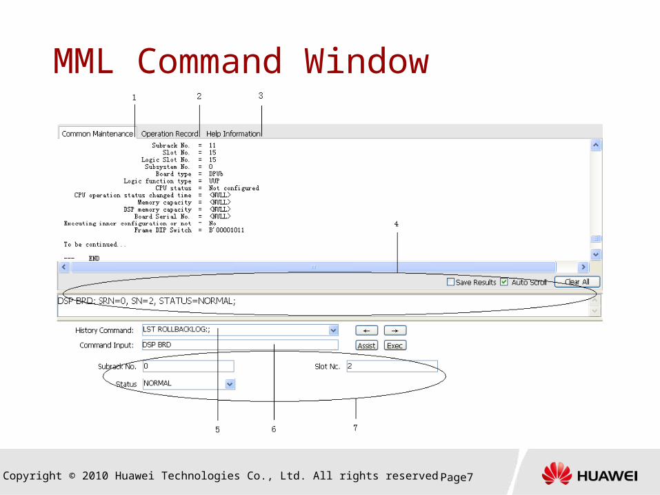
The LMT provides graphical user interface (GUI) for
you to operate and maintain the BSC6900 and BTS.
The alarm management, trace management,
performance monitoring, and device maintenance
can be performed through menu operations.
The MML commands can be run for data
configuration and O&M on the web-LMT.

Copyright © 2010 Huawei Technologies Co., Ltd. All rights reserved. Page6
Web LMT Introduction
Copyright © 2010 Huawei Technologies Co., Ltd. All rights reserved. Page7
MML Command Window

Copyright © 2010 Huawei Technologies Co., Ltd. All rights reserved. Page8
Contents
1. Web LMT Introduction
2. Steps of Data Configuration

Copyright © 2010 Huawei Technologies Co., Ltd. All rights reserved. Page9Page9
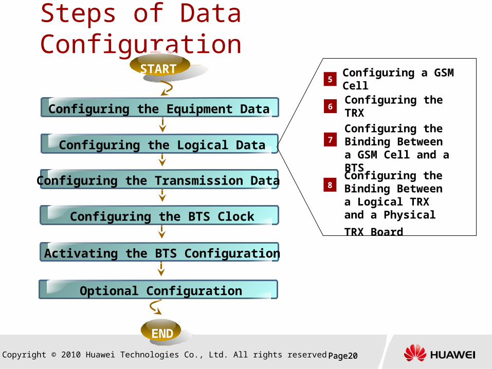
Steps of Data Configuration
END
START
Configuring the Logical Data
Configuring the Equipment Data
Activating the BTS Configuration
Configuring the Transmission Data
Configuring the BTS Clock
Optional Configuration

Copyright © 2010 Huawei Technologies Co., Ltd. All rights reserved. Page10Page10
Steps of Data Configuration
END
START
Configuring the Logical Data
Configuring the Equipment Data
Activating the BTS Configuration
Configuring the Transmission Data
Configuring the BTS Clock
Optional Configuration
ADD BTS1
2
3
ADD BTSCABINET
ADD BTSRXUCHAIN
4ADD BTSRXUBRD
SET BTSRXUBP
Copyright © 2010 Huawei Technologies Co., Ltd. All rights reserved. Page11
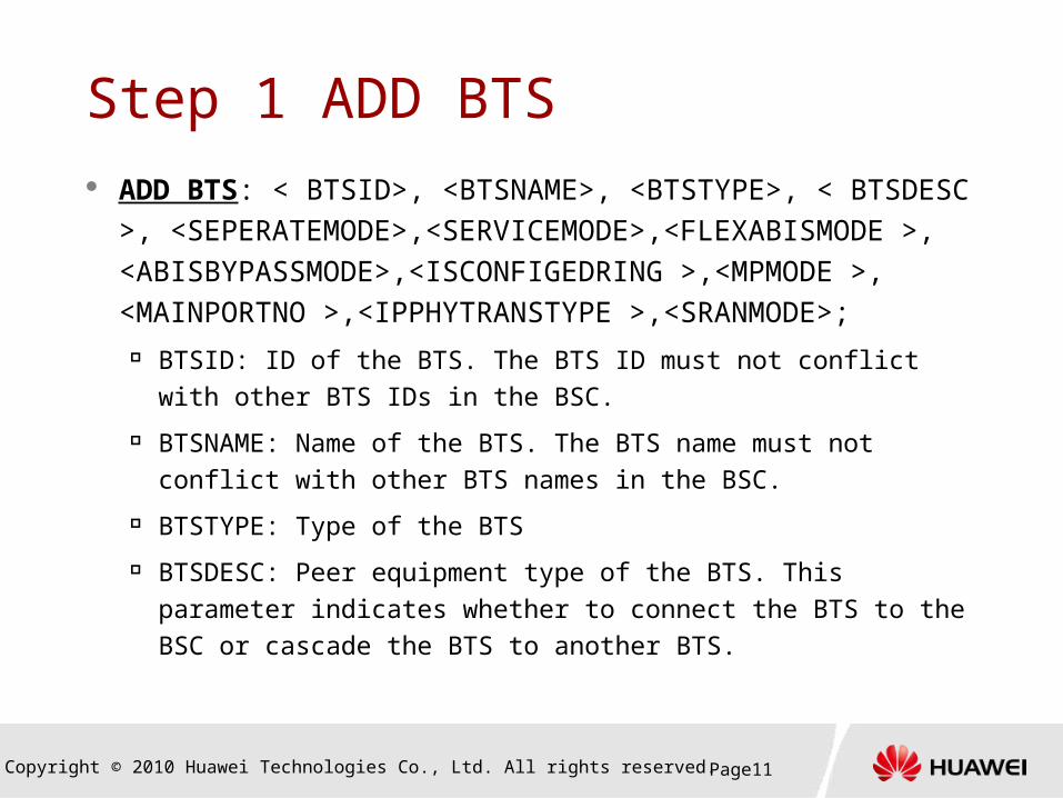
Step 1 ADD BTS ADD BTS: < BTSID>, <BTSNAME>, <BTSTYPE>, <
BTSDESC >, <SEPERATEMODE>,<SERVICEMODE>,<FLEXABISMODE >, <ABISBYPASSMODE>,<ISCONFIGEDRING >,<MPMODE >, <MAINPORTNO >,<IPPHYTRANSTYPE >,<SRANMODE>;
BTSID: ID of the BTS. The BTS ID must not conflict with other BTS IDs in the BSC.
BTSNAME: Name of the BTS. The BTS name must not conflict with other BTS names in the BSC.
BTSTYPE: Type of the BTS
BTSDESC: Peer equipment type of the BTS. This parameter indicates whether to connect the BTS to the BSC or cascade the BTS to another BTS.

Copyright © 2010 Huawei Technologies Co., Ltd. All rights reserved. Page12
Step 1 ADD BTS
ADD BTS
SEPERATEMODE: Whether to enable the BTS to support
the separation between the physical and logical
SERVICEMODE: Service bearer mode of the BTS
FLEXABISMODE: Service timeslot assignment mode for
the BTS
ABISBYPASSMODE: Whether to enable the BTS to
support bypass
ISCONFIGEDRING: Whether to enable the BTS to
support ring networking

Copyright © 2010 Huawei Technologies Co., Ltd. All rights reserved. Page13
Step 1 ADD BTS ADD BTS
MPMODE: Timeslot multiplexing mode at the Abis interface
of the BTS.
MAINPORTNO: Number of the port to which the active OML
of the BTS is connected
PPHYTRANSTYPE: Type of the physical IP transmission
medium
SRANMODE: Whether to enable the BTS to identify an object
in the BTS in normalized mode, for example, to identify a
board by the slot No., subrack No., and cabinet No. and to
identify a transmission port by the port No. in a board

Copyright © 2010 Huawei Technologies Co., Ltd. All rights reserved. Page14
Step 2 ADD BTSCABINET
ADD BTSCABINET: <IDTYPE>, <BTSID>,<CN>,
<SRANMODE>, <TYPE>, <CABINETDESC>;
CN: Number of the cabinet
SRANMODE: Whether to support the SRAN mode
TYPE: Type of a cabinet
CABINETDESC: Descriptive information of the BTS
cabinet

Copyright © 2010 Huawei Technologies Co., Ltd. All rights reserved. Page15
Step 3 ADD BTSRXUCHAIN
ADD BTSRXUCHAIN: <IDTYPE>, <BTSID>, <RCN>,
<TT>, <HCN>,<HSRN>,<HSN>,<HPN>
RCN: Number of the RXU chain or ring
TT: RXU topology type, that is, RXU ring topology or RXU
chain topology.
HCN: Number of the cabinet where the head board of the
RXU chain or ring is located

Copyright © 2010 Huawei Technologies Co., Ltd. All rights reserved. Page16
ADD BTSRXUCHAIN: <IDTYPE>, <BTSID>,
<RCN>, <TT>,
<HCN>,<HSRN>,<HSN>,<HPN>;
HSRN: Number of the subrack where the head board of
the RXU chain or ring is located.
HSN: Number of the slot where the head board of the
RXU chain or ring is located.
HPN: The number of the optical port of the head board
in the RXU chain or ring.
Step 3 ADD BTSRXUCHAIN

Copyright © 2010 Huawei Technologies Co., Ltd. All rights reserved. Page17
Step 4 ADD BTSRXUBRD
ADD BTSRXUBRD: <IDTYPE>, <BTSID>,
<BT>,<CN>,<SRN>,
<SN>,<RXUNAME>,<RXUCHAINNO>,< RXUPOS>
BT: Type of the newly added RXU board
CN: Number of the cabinet
SRN: Number of the subrack where the BTS board is
located
SN: Number of the slot where the BTS board is located
RXUNAME: Name of an RXU

Copyright © 2010 Huawei Technologies Co., Ltd. All rights reserved. Page18
Step 4 ADD BTSRXUBRD
ADD BTSRXUBRD: <IDTYPE>, <BTSID>,
<BT>,<CN>,<SRN>,
<SN>,<RXUNAME>,<RXUCHAINNO>,< RXUPOS>
RXUCHAINNO: Number of the RXU chain where the
board is located
RXUPOS: Position of the RXU board on an RXU chain

Copyright © 2010 Huawei Technologies Co., Ltd. All rights reserved. Page19
Step 4 SET BTSRXUBP SET BTSRXUBP:
<IDTYPE><BTSID><RXUIDTYPE><RXUCHAINNO
><RXUPOS ><RXUTYPE><SndRcvMode
><WORKINGSTANDARD >
SndRcvMode: RFU Antennal Sending Receiving Mode
GUI Value Range: SGL_ANTENNA(Single Feeder[1TX + 1RX]),
SGLDOUBLE_ANTENNA(Single Feeder[1TX + 2RX]),
DOUBLE_ANTENNA(Double Feeder[2TX + 2RX]),
DOUBLEFOUR_ANTENNA(Double Feeder[2TX + 4RX]),
DOUBLESINGLE_ANTENNA(Double Feeder[1TX + 1RX]),
DOUBLEDOUBLE_ANTENNA(Double Feeder[1TX + 2RX])
WORKINGSTANDARD: Working Standard : GU, GO, UO, LTE
Copyright © 2010 Huawei Technologies Co., Ltd. All rights reserved. Page20Page20
Steps of Data Configuration
END
START
Configuring the Logical Data
Configuring the Equipment Data
Activating the BTS Configuration
Configuring the Transmission Data
Configuring the BTS Clock
Optional Configuration
5
6
7
Configuring the TRXConfiguring the Binding Between a GSM Cell and a BTS Configuring the Binding Between a Logical TRX and a Physical TRX
Board
8
Configuring a GSM Cell

Copyright © 2010 Huawei Technologies Co., Ltd. All rights reserved. Page21
Step 5 Configuring a Cell
Configuring a GSM cell involves configuring a cell, mapping
between the cell and the OPC, and frequencies for the cell.
ADD GCELL
This command is used to add GSM internal cells
ADD GCELLFREQ
This command is used to add frequencies to a GSM internal
cell
ADD GCELLOSPMAP
This command is used to add the mapping between a cell and
an originating signaling point (OSP)

Copyright © 2010 Huawei Technologies Co., Ltd. All rights reserved. Page22
Step 5 Configuring a Cell-ADD GCELL ADD GCELL: <CELLID>, <CELLNAME>, <TYPE>,
<MCC>, <MNC>, <LAC>, <CI>;
CELLID: Index of a cell, uniquely identifying a cell in a BSC
CELLNAME: Name of a cell, uniquely identifying a cell in a BSC
TYPE: This parameter specifies the frequency band of new cells.
MCC: Mobile country code
MNC: Mobile network code
LAC: Location area code
CI: Identity code of a cell

Copyright © 2010 Huawei Technologies Co., Ltd. All rights reserved. Page23
Step 5 Configuring a Cell-ADD GCELLFREQ ADD GCELLFREQ: <IDTYPE>, <CELLID>,
<FREQ1>,<FREQ2>;
FREQ1: Frequency 1
FREQ2: Frequency 2
EXAMPLE
ADD GCELLFREQ: IDTYPE=BYID, CELLID=0, FREQ1=1,
FREQ2=2;

Copyright © 2010 Huawei Technologies Co., Ltd. All rights reserved. Page24
Step 5 Configuring a Cell- ADD GCELLOSPMAP ADD GCELLOSPMAP: <IDTYPE>, <CELLID>,
<CELLNAME>, <OPC>;
IDTYPE: Type of an index
CELLID: Index of a cell, uniquely identifying a cell in a BSC
CELLNAME: Name of a cell, uniquely identifying a cell in a
BSC
OPC: Code of the original signaling point (OSP) in the
signaling network
EXAMPLE
ADD GCELLOSPMAP: IDTYPE=BYID, CELLID=0, OPC=1000;

Copyright © 2010 Huawei Technologies Co., Ltd. All rights reserved. Page25
Step 6 Configuring the TRX
Configuring the TRX for the BTS. This involves
configuring the logical TRX and BCCH.
ADD GTRX This command is used to add a logical TRX and configure the
binding between the logical TRX and the cell

Copyright © 2010 Huawei Technologies Co., Ltd. All rights reserved. Page26
Step 6 Configuring the TRX-ADD GTRX ADD GTRX: < IDTYPE>, <CELLID>, <TRXID>,
<FREQ> , <ISMAINBCCH>;
TRXID: ID of the TRX. The TRX ID must be globally
unique
FREQ: Frequency of the TRX, Value Range: 0~1023
ISMAINBCCH: Whether to enable the TRX to carry the
main BCCH in the cell

Copyright © 2010 Huawei Technologies Co., Ltd. All rights reserved. Page27
Step 7 Configuring the Binding Between a GSM Cell and a BTS ADD CELLBIND2BTS: <IDTYPE>, <CELLID>,
<BTSID>;
IDTYPE: Type of an index
CELLID: Index of a cell, uniquely identifying a cell in a
BSC
CELLNAME: Name of a cell, uniquely identifying a cell
in a BSC
BTSID: ID of the BTS
BTSNAME: Name of the BTS
Copyright © 2010 Huawei Technologies Co., Ltd. All rights reserved. Page28
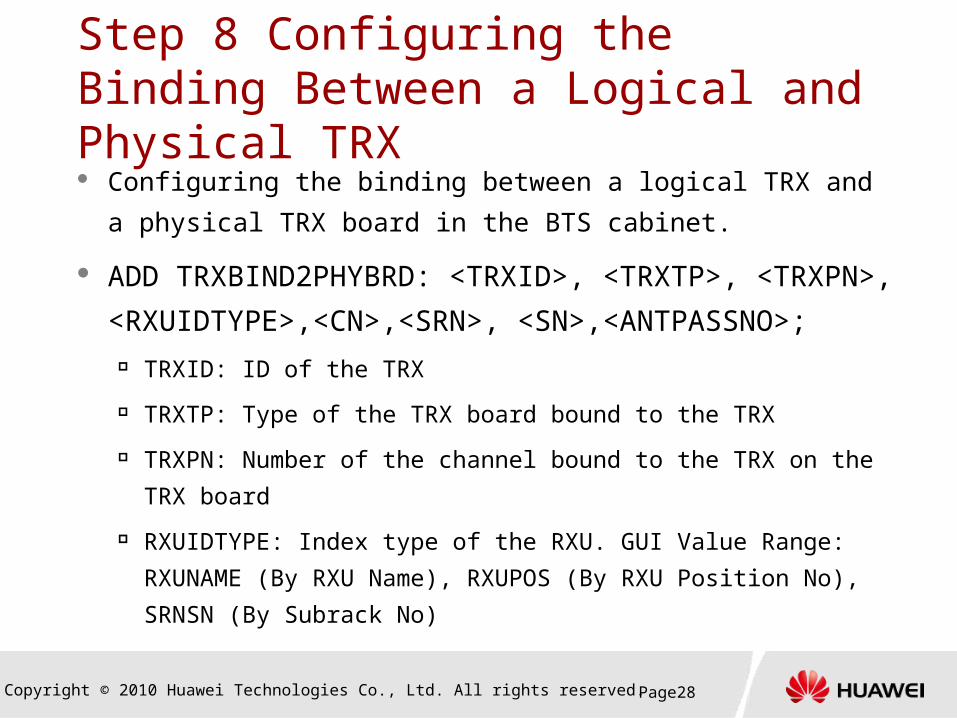
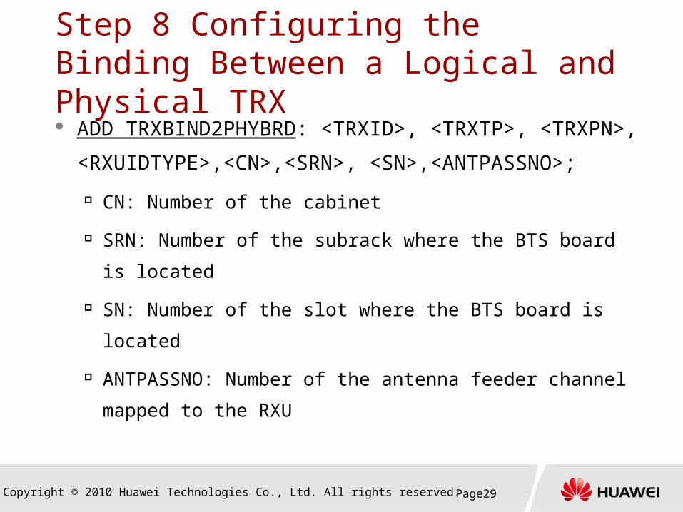
Step 8 Configuring the Binding Between a Logical and Physical TRX Configuring the binding between a logical TRX and a physical
TRX board in the BTS cabinet.
ADD TRXBIND2PHYBRD: <TRXID>, <TRXTP>, <TRXPN>,
<RXUIDTYPE>,<CN>,<SRN>, <SN>,<ANTPASSNO>; TRXID: ID of the TRX
TRXTP: Type of the TRX board bound to the TRX
TRXPN: Number of the channel bound to the TRX on the TRX board
RXUIDTYPE: Index type of the RXU. GUI Value Range: RXUNAME
(By RXU Name), RXUPOS (By RXU Position No), SRNSN (By
Subrack No)
Copyright © 2010 Huawei Technologies Co., Ltd. All rights reserved. Page29
Step 8 Configuring the Binding Between a Logical and Physical TRX ADD TRXBIND2PHYBRD: <TRXID>, <TRXTP>,
<TRXPN>, <RXUIDTYPE>,<CN>,<SRN>,
<SN>,<ANTPASSNO>;
CN: Number of the cabinet
SRN: Number of the subrack where the BTS board is
located
SN: Number of the slot where the BTS board is located
ANTPASSNO: Number of the antenna feeder channel
mapped to the RXU
Copyright © 2010 Huawei Technologies Co., Ltd. All rights reserved. Page30
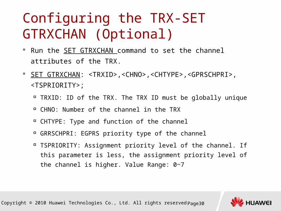
Configuring the TRX-SET GTRXCHAN (Optional) Run the SET GTRXCHAN command to set the channel attributes
of the TRX.
SET GTRXCHAN: <TRXID>,<CHNO>,<CHTYPE>,<GPRSCHPRI>,
<TSPRIORITY>;
TRXID: ID of the TRX. The TRX ID must be globally unique
CHNO: Number of the channel in the TRX
CHTYPE: Type and function of the channel
GRRSCHPRI: EGPRS priority type of the channel
TSPRIORITY: Assignment priority level of the channel. If this
parameter is less, the assignment priority level of the channel is
higher. Value Range: 0~7

Copyright © 2010 Huawei Technologies Co., Ltd. All rights reserved. Page31
Configuring the TRX-SET GTRXDEV (Optional) Run the SET GTRXDEV command to set the device attributes of
the TRX.
SET GTRXDEV: <POWL >,<POWT >,<OPTL >,<SDFLAG >, <TCHAJFLAG >,<PL8PSK >,<RCVMD > ,<SNDMD >, <CPS >
POWL: Power Level
POWT: Power Type
OPTL: TRX Priority
SDFLAG: Shut Down Enabled
TCHAJFLAG: TCH Rate Adjust Allow
PL8PSK: TRX 8PSK Level
RCVMD: Receive Mode
SNDMD: Send Mode
CPS: Allow Dynamic Shutdown TRX

Copyright © 2010 Huawei Technologies Co., Ltd. All rights reserved. Page32Page32
Steps of Data Configuration
END
START
Configuring the Logical Data
Configuring the Equipment Data
Activating the BTS Configuration
Configuring the Transmission Data
Configuring the BTS Clock
Optional Configuration
TDM/HDLC1
IP Over FE/GE
IP Over E1
2
3

Copyright © 2010 Huawei Technologies Co., Ltd. All rights reserved. Page33
Configuring TDM/HDLC Transmission Data ADD BTSCONNECT: <IDTYPE>, <BTSID>, <INPN>,
<DESTNODE>, <SRN>, <SN>, <PN>; INPN: Number of a BTS port
INCN: Number of the in-port cabinet on a BTS
INSRN: Number of the in-port subrack on a BTS
INSN: Number of the in-port slot on a BTS
DESTNODE: Type of the object that connects to the BTS.
Value range: BTS, BSC6900, and DXX

Copyright © 2010 Huawei Technologies Co., Ltd. All rights reserved. Page34
ADD BTSCONNECT: <IDTYPE>, <BTSID>, <INPN>,
<DESTNODE>, <SRN>, <SN>, <PN>;
SRN: Number of the subrack where the BSC6900 board
connected to the BTS is located
SN: Number of the slot
PN: Number of the port through which the BTS is connected
to the BSC6900
EXAMPLE
ADD BTSCONNECT: IDTYPE=BYID, BTSID=1, INPN=0,
DESTNODE=BSC, SRN=11, SN=0, PN=1;
Configuring TDM/HDLC Transmission Data
Copyright © 2010 Huawei Technologies Co., Ltd. All rights reserved. Page35
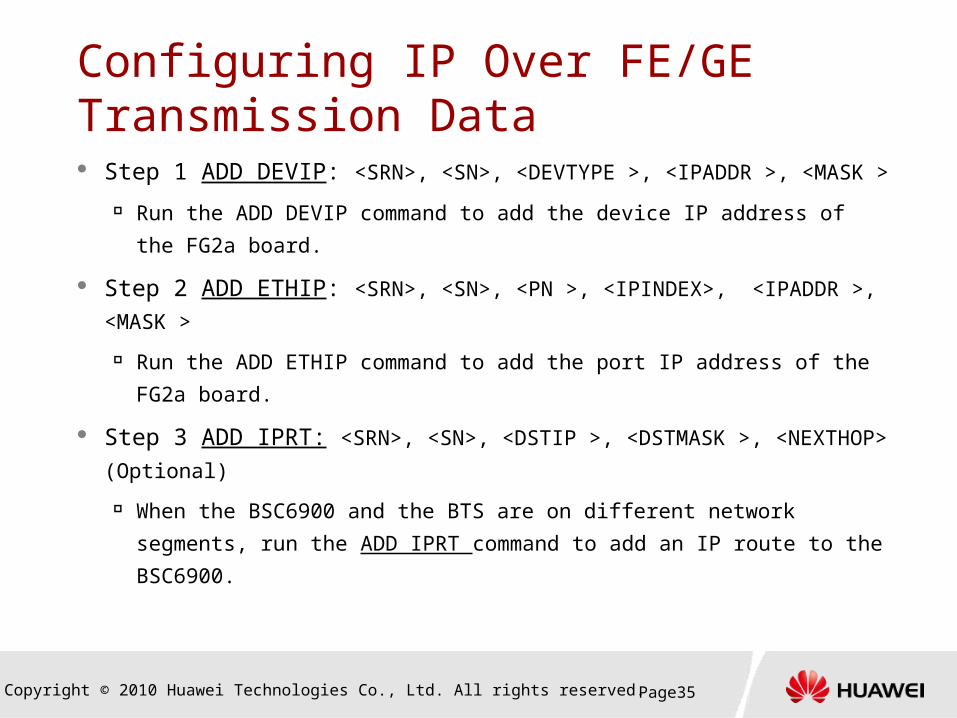
Step 1 ADD DEVIP: <SRN>, <SN>, <DEVTYPE >, <IPADDR >,
<MASK >
Run the ADD DEVIP command to add the device IP address of the
FG2a board.
Step 2 ADD ETHIP: <SRN>, <SN>, <PN >, <IPINDEX>, <IPADDR >,
<MASK >
Run the ADD ETHIP command to add the port IP address of the
FG2a board.
Step 3 ADD IPRT: <SRN>, <SN>, <DSTIP >, <DSTMASK >,
<NEXTHOP> (Optional)
When the BSC6900 and the BTS are on different network segments,
run the ADD IPRT command to add an IP route to the BSC6900.
Configuring IP Over FE/GE Transmission Data
Copyright © 2010 Huawei Technologies Co., Ltd. All rights reserved. Page36
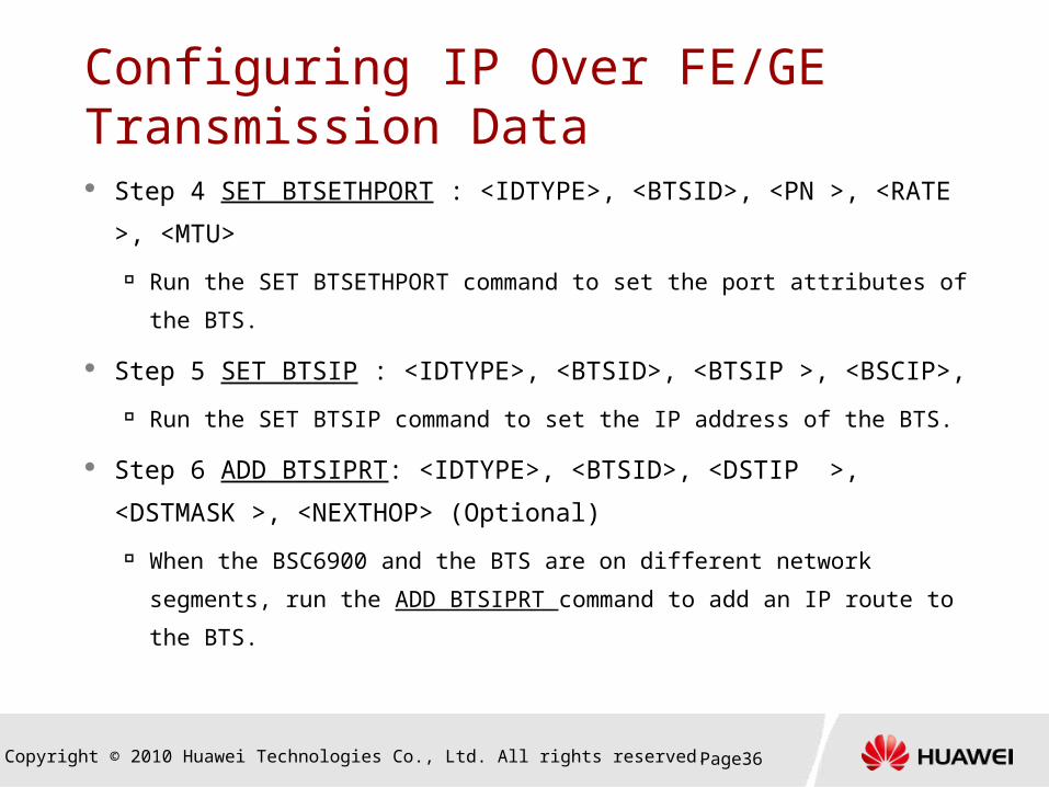
Step 4 SET BTSETHPORT : <IDTYPE>, <BTSID>, <PN >,
<RATE >, <MTU>
Run the SET BTSETHPORT command to set the port attributes of
the BTS.
Step 5 SET BTSIP : <IDTYPE>, <BTSID>, <BTSIP >, <BSCIP>,
Run the SET BTSIP command to set the IP address of the BTS.
Step 6 ADD BTSIPRT: <IDTYPE>, <BTSID>, <DSTIP >,
<DSTMASK >, <NEXTHOP> (Optional)
When the BSC6900 and the BTS are on different network
segments, run the ADD BTSIPRT command to add an IP route to
the BTS.
Configuring IP Over FE/GE Transmission Data
Copyright © 2010 Huawei Technologies Co., Ltd. All rights reserved. Page37
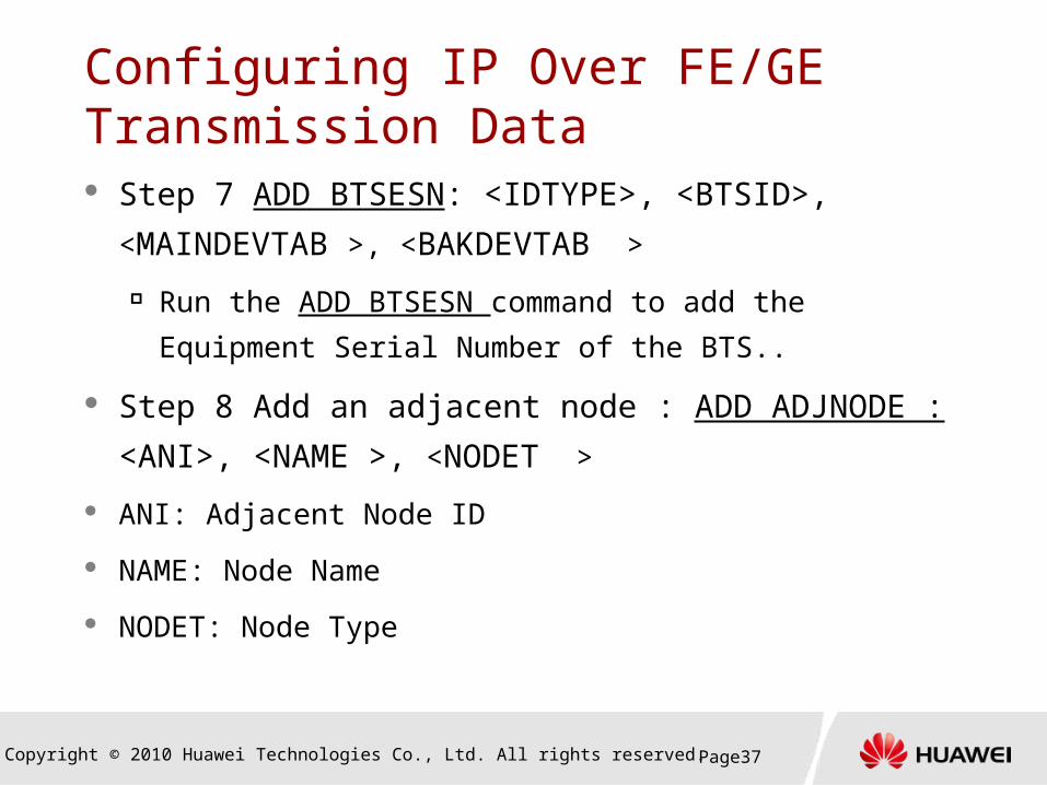
Step 7 ADD BTSESN: <IDTYPE>, <BTSID>,
<MAINDEVTAB >, <BAKDEVTAB >
Run the ADD BTSESN command to add the Equipment
Serial Number of the BTS..
Step 8 Add an adjacent node : ADD ADJNODE :
<ANI>, <NAME >, <NODET >
ANI: Adjacent Node ID
NAME: Node Name
NODET: Node Type
Configuring IP Over FE/GE Transmission Data
Copyright © 2010 Huawei Technologies Co., Ltd. All rights reserved. Page38
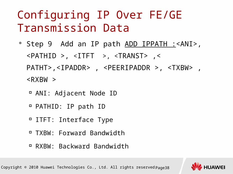
Step 9 Add an IP path ADD IPPATH :<ANI>,
<PATHID >, <ITFT >, <TRANST> ,<
PATHT>,<IPADDR> , <PEERIPADDR >, <TXBW> ,
<RXBW >
ANI: Adjacent Node ID
PATHID: IP path ID
ITFT: Interface Type
TXBW: Forward Bandwidth
RXBW: Backward Bandwidth
Configuring IP Over FE/GE Transmission Data

Copyright © 2010 Huawei Technologies Co., Ltd. All rights reserved. Page39
Step 1 ADD BTSCONNECT: <IDTYPE>, <BTSID>,
<INPN>, <DESTNODE>, <SRN>, <SN>, <PN>;
Run the ADD BTSCONNECT command to add a
connection between the BTS and the BSC6900.
Step 2 ADD a PPP link (Optional)
ADD PPPLNK: <SRN>, <SN>, <BRDTYPE >, <PPPLNKN >,
<TSBITMAP> ,<LOCALIP>, <PEERIP>
ADD BTSPPPLNK: <IDTYPE>, <BTSID>, <PPPLNKN >,
<PN >, <TSBITMAP>
Configuring IP Over E1 Transmission Data
Copyright © 2010 Huawei Technologies Co., Ltd. All rights reserved. Page40
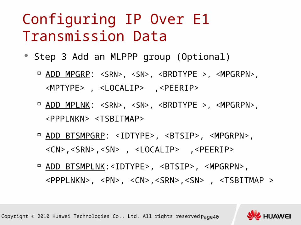
Step 3 Add an MLPPP group (Optional)
ADD MPGRP: <SRN>, <SN>, <BRDTYPE >, <MPGRPN>,
<MPTYPE> , <LOCALIP> ,<PEERIP>
ADD MPLNK: <SRN>, <SN>, <BRDTYPE >, <MPGRPN>,
<PPPLNKN> <TSBITMAP>
ADD BTSMPGRP: <IDTYPE>, <BTSIP>, <MPGRPN>,
<CN>,<SRN>,<SN> , <LOCALIP> ,<PEERIP>
ADD BTSMPLNK:<IDTYPE>, <BTSIP>, <MPGRPN>,
<PPPLNKN>, <PN>, <CN>,<SRN>,<SN> , <TSBITMAP
>
Configuring IP Over E1 Transmission Data
Copyright © 2010 Huawei Technologies Co., Ltd. All rights reserved. Page41
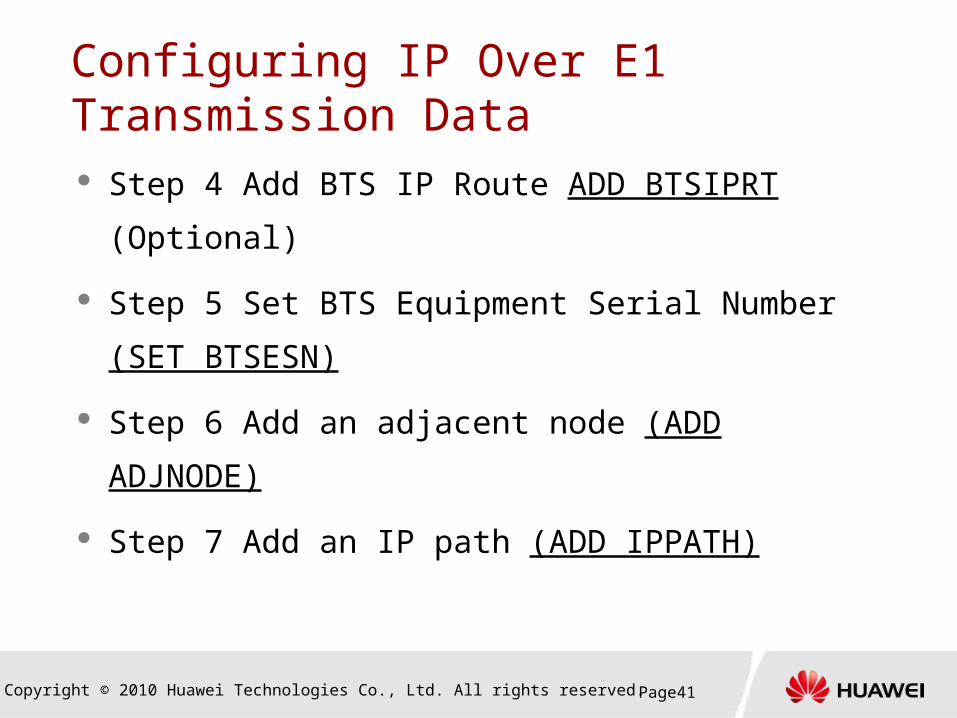
Step 4 Add BTS IP Route ADD BTSIPRT
(Optional)
Step 5 Set BTS Equipment Serial Number (SET
BTSESN)
Step 6 Add an adjacent node (ADD ADJNODE)
Step 7 Add an IP path (ADD IPPATH)
Configuring IP Over E1 Transmission Data

Copyright © 2010 Huawei Technologies Co., Ltd. All rights reserved. Page42Page42
Steps of Data Configuration
END
START
Configuring the Logical Data
Configuring the Equipment Data
Activating the BTS Configuration
Configuring the Transmission Data
Configuring the BTS Clock
Optional Configuration
SET BTSIPCLKPARA
1
SET BTSCLK2

Copyright © 2010 Huawei Technologies Co., Ltd. All rights reserved. Page43
Set BTS IP Clock Server
Set BTS IP Clock Server SET BTSIPCLKPARA :<BTSID>,
< CLKPRTTYPE >, < SYNMODE >,< SYNTIMEDAY >,<
SYNTIMEHOUR >, < SYNTIMEMIN >,< MASTERIPADDR >,
BTSID: BTD Index
CLKPRTTYPE : Clock Protocol Type
SYNMODE : Clock Synchronization Mode
SYNTIMEDAY : Days of Inter Sync Period
SYNTIMEHOUR : Hours of Inter Sync Period
SYNTIMEMIN : Minutes of Inter Sync Period
MASTERIPADDR : Master Clock Server IP Address
Copyright © 2010 Huawei Technologies Co., Ltd. All rights reserved. Page44
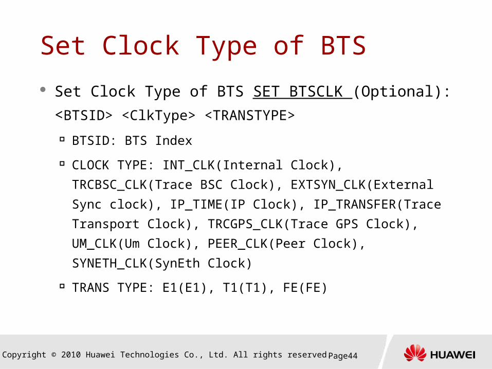
Set Clock Type of BTS SET BTSCLK (Optional):
<BTSID> <ClkType> <TRANSTYPE>
BTSID: BTS Index
CLOCK TYPE: INT_CLK(Internal Clock), TRCBSC_CLK(Trace
BSC Clock), EXTSYN_CLK(External Sync clock), IP_TIME(IP
Clock), IP_TRANSFER(Trace Transport Clock),
TRCGPS_CLK(Trace GPS Clock), UM_CLK(Um Clock),
PEER_CLK(Peer Clock), SYNETH_CLK(SynEth Clock)
TRANS TYPE: E1(E1), T1(T1), FE(FE)
Set Clock Type of BTS

Copyright © 2010 Huawei Technologies Co., Ltd. All rights reserved. Page45Page45
Steps of Data Configuration
END
START
Configuring the Logical Data
Configuring the Equipment Data
Activating the BTS Configuration
Configuring the Transmission Data
Configuring the BTS Clock
Optional Configuration
ACT BTS

Copyright © 2010 Huawei Technologies Co., Ltd. All rights reserved. Page46
Activating the BTS Configuration CHK BTS :<IDTYPE>, <BTSID>;
Use this command to check the BTS data integrity.
ACT BTS: <IDTYPE>, <BTSID>;
IDTYPE: Index type of the BTS.
BTSID: ID of the BTS.
BTSNAME: Name of the BTS

Copyright © 2010 Huawei Technologies Co., Ltd. All rights reserved. Page47Page47
Optional Configuration
END
START
Configuring the Logical Data
Configuring the Equipment Data
Activating the BTS Configuration
Configuring the Transmission Data
Configuring the BTS Clock
Optional Configuration
1
2
Neighboring cell relations configurationGPRS/EDGE configuration
Copyright © 2010 Huawei Technologies Co., Ltd. All rights reserved. Page48Page48
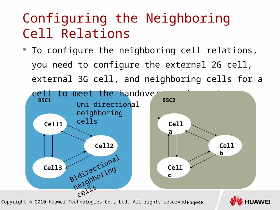
Configuring the Neighboring Cell Relations To configure the neighboring cell relations, you need to
configure the external 2G cell, external 3G cell, and
neighboring cells for a cell to meet the handover
requirement.BSC1
Cell1
Cell2
Cell3
BSC2
Cell a
Cell b
Cell c
Uni-directional neighboring cells
Bidirectional
neighboring cells

Copyright © 2010 Huawei Technologies Co., Ltd. All rights reserved. Page49Page49
Configuring the Neighboring Cell Relations Add a 2G external cell. (ADD GEXT2GCELL)
Add a 3G external cell. (ADD GEXT3GCELL)
Add a 2G neighboring cell for the specified
originating cell. (ADD G2GNCELL)
Add a 3G neighboring cell for the specified
originating cell. (ADD G3GNCELL)

Copyright © 2010 Huawei Technologies Co., Ltd. All rights reserved. Page50Page50
Configuring the Neighboring Cell Relations Add a 2G external cell. (ADD GEXT2GCELL)
Add a 2G neighboring cell for the specified originating
cell. (ADD G2GNCELL)

Copyright © 2010 Huawei Technologies Co., Ltd. All rights reserved. Page51
Configuring GPRS/EDGE
Page51
To configure GPRS/EDGE the cell need to be enable
with packet channels. Also the cell should be activated
with GPRS and EDGE function, according to
requirement.
Cell, with no GPRS/EDGE
Cell with GPRS
Cell with GPRS and EDGE

Copyright © 2010 Huawei Technologies Co., Ltd. All rights reserved. Page52
Configuring GPRS/EDGE Run the ( SET GCELLGPRS) command to set the parameters
as follows:
If external PCU is used, set GPRS to
SupportAsExtPcu(Support as external Pcu)
If built-in PCU is used, set GPRS to
SupportAsInnPcu(Support as built-in PCU)
If EDGE is used in the cell set EDGE to YES
Copyright © 2010 Huawei Technologies Co., Ltd. All rights reserved. Page53
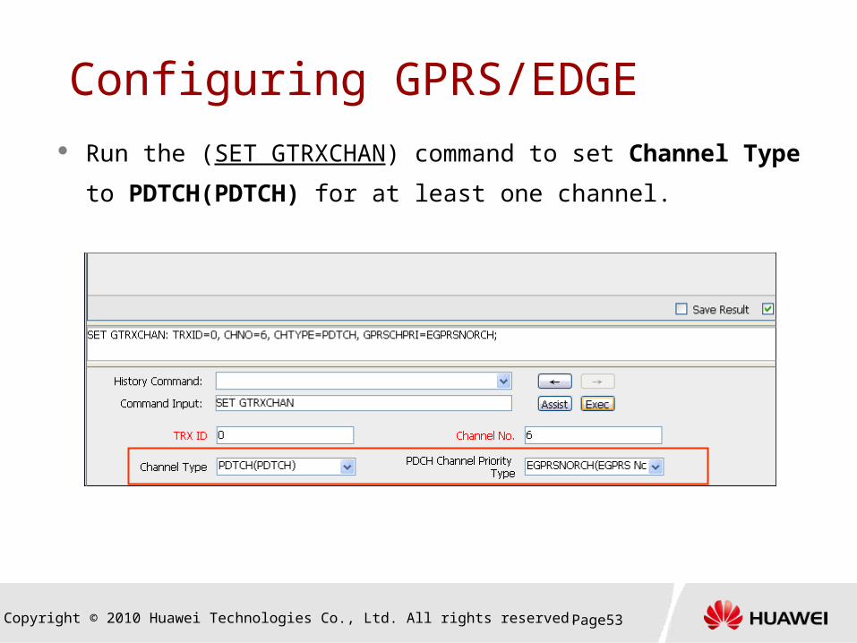
Configuring GPRS/EDGE Run the (SET GTRXCHAN) command to set Channel Type
to PDTCH(PDTCH) for at least one channel.

Copyright © 2010 Huawei Technologies Co., Ltd. All rights reserved. Page54
Configuring GPRS/EDGE To set idle timeslots for data (in TDM transmission mode) :
(SET BTSIDLETS)
To set IPPATH for data (in IP transmission mode) : (ADD
IPPATH)

Copyright © 2010 Huawei Technologies Co., Ltd. All rights reserved. Page55
Summary
The concept of Web LMT
Initial GSM data configuration steps of BTS3900
Configuring the Equipment Data, Logical Data,
Transmission Data, Clock Data
Activating the BTS Configuration Optional Configuration

Thank youwww.huawei.com