om wilo actun opti ms 6084879 03 en
TRANSCRIPT

6084879·Ed.03/2021-01 DIN A5
Wilo-Actun OPTI-MS...
Pioneering for You
en Installation and operating instructions
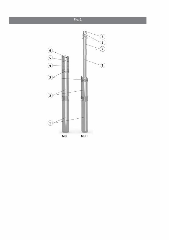
Fig. 1
MSI MSH
1
2
3
4
5
6
6
5
17
8

Fig. 2
1
3
2
5
4
1
3
2
7
65
4
32
78
65
4
1
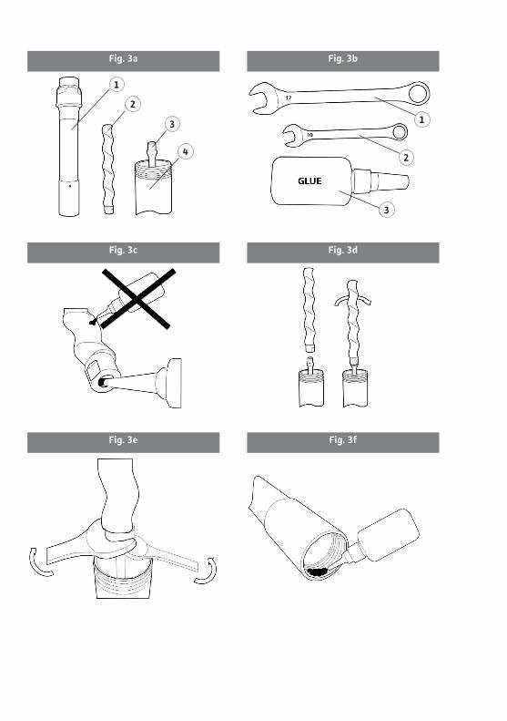
Fig. 3fFig. 3e
Fig. 3bFig. 3a
Fig. 3dFig. 3c
1
2
3
4
1
2
3

Fig. 3hFig. 3g
Fig. 3jFig. 3i
Fig. 4bFig. 4a
Fig. 4c
1
5 4 3
2
6 7
1
8
4
7

Fig. 6
7
8
Fig. 5
2 31 65
24 5 6
3
1

Fig. 7
2,5 m
A A B
1
2


Installation and operating instructions Wilo-Actun OPTI-MS... 9
English
1. Introduction 101.1. About this manual 101.2. Copyright 101.3. Subject to changes 101.4. Warranty 10
2. Safety 112.1. Identification of safety instructions 112.2. Personnel qualifications 132.3. Electrical work 132.4. Monitoring devices 142.5. During operation 142.6. Fluids 152.7. Operator’s obligations 15
3. Application/Use 163.1. Intended use 163.2. Improper use 17
4. Product description 174.1. Design 174.2. How it works 194.3. Monitoring devices 194.4. Operating modes 204.5. Technical data 204.6. Scope of delivery 214.7. Accessories (optionally available) 21
5. Transport and storage 215.1. Delivery 215.2. Transport 225.3. Storage 235.4. Return delivery 24
6. Installation 246.1. General 246.2. Installation types 256.3. Electrical connection 276.4. Motor protection 306.5. Installation 306.6. Dry-running protection 35
7. Commissioning 367.1. Electrical system 377.2. Initial commissioning 377.3. Operation 387.4. Conduct during operation 39
8. Decommissioning/Disposal 398.1. Temporary shutdown 408.2. Shutdown for maintenance work
or storage 408.3. Recommissioning 418.4. Disposal 41
9. Maintenance and repair 42
10. Troubleshooting 4210.1. Faults 42
11. Appendix 4411.1. Spare parts 44

10 WILO SE 2021-01 DIN A5
English INTRODUCTION
1. Introduction
1.1. About this manualThe installation and operating instructions are an integral part of the product. Read these instructions before all activities and keep them accessible at all times. Strict ob-servance of these instructions is a prerequisite for the intended use and correct handling of the product. Observe all information and markings on the product.The original operating instructions were written in German. All other languages of these instructions are translations of the original operating instructions.
1.2. CopyrightThis operating and maintenance manual has been copyrighted by the manufacturer. Under no circumstances may any of the content be reproduced, distributed or used for any competitive purpose without authorization and handed to third parties.
1.3. Subject to changesThe manufacturer reserves the right to make technical modifications to the product or individual components. Illustrations used may differ from the original and serve only as example illustrations of the product.
1.4. WarrantyFor the warranty and warranty period the information in the current “General Terms and Conditions” applies (see: www.wilo.com/legal).Any deviations must be contractually agreed and shall then be given priority.
Warranty claimsProvided that the following points have been adhered to, the manufacturer is obliged to repair any qualitative or constructive defects:
• The defects were reported in writing to the manufacturer within the warranty period.• Application according to intended use.• All monitoring devices are connected and were checked before commissioning.
DisclaimerA disclaimer rules out any liability for personal injury, material damage or financial losses. This exclusion of liability follows as soon as one of the following points applies:
• Inadequate configuration due to unsatisfactory or false information provided by the operator or employer
• Non-observance of the Installation and Operating Instructions• Improper use• Improper storage or transport• Faulty installation or dismantling• Insufficient or incorrect maintenance• Unauthorized repairs
Installation and operating instructions Wilo-Actun OPTI-MS... 11
SAFETY English
• Inadequate installation site• Chemical, electrical or electrochemical influences• Wear
2. SafetyThis section contains basic indications which must be observed during the individu-al phases of life. Failure to observe these installation and operating instructions may endanger people, the environment as well as the product and lead to the loss of any damages claims. A failure to observe may bring about the following dangers:
• Danger to persons due to electrical, mechanical and bacteriological effects as well as electromagnetic fields
• Danger to the environment due to leakage of hazardous substances• Material damage• Failure of important functions of the product
In addition, observe the instructions and safety instructions in the following sections!
2.1. Identification of safety instructionsIn these installation and operating instructions, safety instructions are used for material damage and personal injury. These safety instructions are illustrated differently:
• Safety instructions for personal injury start with a signal word, have a corresponding prefixed symbol and are grayed out.
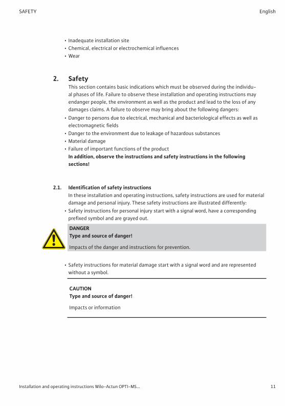
DANGER Type and source of danger!
Impacts of the danger and instructions for prevention.
• Safety instructions for material damage start with a signal word and are represented without a symbol.
CAUTION Type and source of danger!
Impacts or information

12 WILO SE 2021-01 DIN A5
English SAFETY
Signal words• DANGER!
Non-compliance causes death or serious injury!• WARNING!
Non-compliance can cause (serious) injury!• CAUTION!
Non-compliance can cause material damage or even total loss.• NOTICE!
Useful information about handling the product
SymbolsThe following symbols are used in these instructions:
Danger symbol: General hazard
Danger symbol, for example, electrical current
Danger symbol: Risk of cuts
Danger symbol: Risk caused by electromagnetic waves
Danger symbol: Risk of explosion
Danger symbol: Suspended loads
Danger symbol: Risk of falling

Installation and operating instructions Wilo-Actun OPTI-MS... 13
SAFETY English
Danger symbol: Hot surfaces
Danger symbol: Risk of crushing
Useful information
2.2. Personnel qualificationsPersonnel must:
• Be informed of the locally applicable accident prevention regulations.• Have read and understood the installation and operating instructions.
The personnel must have the following qualifications:• Electrical work: A qualified electrician must carry out the electrical work.• Installation/dismantling work: The technician must be trained to handle the necessary
tools and required fixation materials for the available installation site.• Maintenance work: The technician must be familiar with the use of operating fluids and
their disposal. Furthermore, the technician must have basic knowledge of engineering.
Definition “Qualified Electrician”A qualified electrician is someone with suitable technical training, knowledge and expe-rience who can identify and avoid the dangers associated with electricity.
2.3. Electrical work• A qualified electrician must carry out the electrical work.• When connecting to the power supply, adhere to the local regulations as well as the
provisions of the local energy supply company.• Before all work, disconnect the product from the power supply and take measures to
prevent unauthorized switch-on.• The personnel is instructed in how to implement the electrical connection as well as in
the shutdown methods of the product.• Adhere to the technical information in these installation and operating instructions as
well as on the rating plate.• Ground the product.• Observe the manufacturer’s regulations when connecting to electrical switchgears.• Immediately replace faulty connection cables. Contact customer service.

14 WILO SE 2021-01 DIN A5
English SAFETY
2.4. Monitoring devicesThe following monitoring devices must be provided by the customer if the pump is connected to a power supply grid:
Circuit breaker• Install the circuit breaker in accordance with the manufacturer instructions. Observe
local regulations.• Further protection devices (e.g. overvoltage, undervoltage, or phase-failure relay, etc.)
must be provided on-site for sensitive power supplies.
Residual-current device (RCD)• Adhere to the regulations of the local energy supply company! We recommend using a
residual-current device.• If persons could come into contact with the product and conductive liquids, secure
connection with a residual-current device (RCD).
2.5. During operationWhen operating the pump, always follow the locally applicable laws and regulations for work safety, accident prevention, and handling electrical machinery.The operator must specify a personnel work plan for a safe workflow. All personnel is responsible for ensuring that regulations are observed.The pump is equipped with moving parts. During operation, these parts rotate in order to pump the fluid. Certain substances in the fluid can result in very sharp edges forming on the moving parts.
WARNING: rotating parts! The rotating parts can crush and sever limbs. Do not reach into the hydraulics or touch the rotating parts when the machine is in operation. Switch off the pump and allow the rotating parts to come to a standstill prior to maintenance and repair work!

Installation and operating instructions Wilo-Actun OPTI-MS... 15
SAFETY English
2.6. FluidsEach fluid differs in respect of composition, corrosiveness, abrasiveness, dry matter content, and in many other aspects. Generally, our pumps can be used for many appli-cations. Please note that if requirements change (density, viscosity or general composi-tion), this can also affect many operating parameters of the pump.If the pump is used in or switched over to a different fluid, observe the following:
• For use in drinking water applications, make sure that all parts that come into contact with the medium are suitable for such use. This must be checked in accordance with the local regulations and laws.The pumps must not be used in wastewater and sewage and/or with fluids that are hazardous to health.
2.7. Operator’s obligations• Provide the installation and operating instructions in a language that personnel can
understand.• Ensure the required level of training of personnel for the specified work.• Provide the required protective equipment and ensure that the personnel wear the
protective equipment.• Ensure that the attached safety and information signs on the product are always legible.• Instruct personnel in how the system operates.• Eliminate any potential risks posed by electricity.• Fit dangerous components within the system with an on-site guard.• Secure and mark the work area.• Define a personnel work plan for safe workflow.
Children and persons under 16 years of age or with limited physical, sensory or cognitive capacities are prohibited from handling the product! Persons under 18 years of age must be supervised by a technician!

16 WILO SE 2021-01 DIN A5
English APPLICATION/USE
3. Application/UseDANGER: electrical hazard When using the pump in swimming pools or other basins that can be entered, there is a risk of electrocution.
NOTE:
• Use is strictly forbidden if there are people in the pool or basin!
• If there are no people in the basin, protec-tive measures must be taken according to DIN EN 62638 (or the appropriate national regulations).
RISK of fatal injury from magnetic field! The permanently magnetized rotor inside the motor presents an acute danger to persons with pace-makers. Non-observance may result in death or the most serious of injuries.
• Do not open the motor!• Only allow Wilo customer service to dismantle
and install the rotor for maintenance and repair work.
• Persons with pacemakers must observe the gen-eral behavioral guidelines applicable to handling electrical devices when working on the pump!
NOTICE: The magnets inside the motor do not pose a danger provided the motor is completely mounted. As such, the pump assembly does not pose a special danger to persons with pacemakers, who can safely approach a pump without any restrictions.
3.1. Intended useSubmersible pumps are suitable for:
• Water supply from boreholes, wells and rainwater storage tanks.• Domestic and commercial water supply, sprinkling and irrigation.• Pumping water without long-fiber and abrasive constituents.

Installation and operating instructions Wilo-Actun OPTI-MS... 17
PRODUCT DESCRIPTION English
Pumping drinking waterWhen used to pump drinking water, the local guidelines/laws/regulations must be checked to establish whether the pump is suitable for this application.Pumps do not meet the specifications of the German drinking water regulations (TrinkwV) and they have not been approved as per ACS or local guidelines, such as KTW and elastomer guideline.
3.2. Improper use
DANGER – explosive fluids! It is strictly prohibited to pump explosive fluids (gasoline, kerosene etc.). The pumps are not de-signed for these fluids!
NOTICE: Submersible pumps must not be connected to the public power supply network! They are designed to be supplied exclusively from
• Photovoltaic systems• Independent AC power sources or networks sup-
plied by these sources
Submersible pumps must not be used for pumping:• Wastewater• Sewage/faeces• Untreated sewage
Intended use also includes observance of these instructions. Any use other than the intended use is regarded as improper use.
4. Product description
4.1. DesignFully submersible, multistage submersible pump with integrated non-return valve to supply wastewater and drinking water, available as centrifugal pump in flanged bowl construction (MSI) or progressive cavity pump (MSH).The unit can be installed vertically or horizontally. The motor is cooled by the pumped fluid. Therefore, the unit must always be operated immersed. The limit values for maxi-mum fluid temperature, minimum flow rate and voltage ranges must be adhered to.Vertical installation is possible with or without cooling shroud depending on the config-uration. In cases of horizontal installation, a cooling shroud must always be provided.

18 WILO SE 2021-01 DIN A5
English PRODUCT DESCRIPTION
Fig. 1: Description of the submersible pump
1 Internal frequency converter 5 Non-return valve
2 Permanent magnet motor 6 Pressure connection
3 Suction piece 7Stator tube with eccentric screw (MSH)
4 Multistage hydraulics (MSI) 8 Support pipe (MSH)
4.1.1. HydraulicsThe pump is not self-priming, i.e. the fluid must flow in either automatically or with supply pressure and the minimum submersion (2.5 m) must be ensured at all times.
Actun OPTI-MSIMultistage hydraulics with radial impellers in sectional construction. The hydraulics housing, the pump shaft and the impellers are made of stainless steel. The connection on the pressure side is designed as a vertical threaded flange with a female thread and integrated non-return valve.
Actun OPTI-MSHProgressive cavity pump featuring eccentric screw within a double-helix rubber stator.The hydraulics housing, the pump shaft and the eccentric screw are made of stainless steel. The connection on the pressure side is designed as a vertical threaded flange with a female thread and integrated non-return valve.
4.1.2. MotorThe drive unit is a stainless, encapsulated permanent magnet motor featuring inte-grated frequency converter. The permanent magnet motor has been cast hermetically featuring coiling insulated by paint, it has been resin-impregnated and features self- lubricating bearings.The motor is cooled by the pumped fluid. Therefore, the motor must always be operated immersed. The limit values for maximum fluid temperature and minimum flow velocity must be adhered to.The integrated frequency converter enables operation with AC or DC power sources. Consequently, the Actun OPTI-MS pump is particularly suitable for operation with solar power. In applications with solar modules the integrated MPPT (Maximum Power Point Tracking) algorithm enables an adaption to the available power to maximize the pumped flow rate (dynamic MPPT).The connection cable has bare cable ends, is longitudinally watertight and is connected to the motor by a detachable plug.

Installation and operating instructions Wilo-Actun OPTI-MS... 19
PRODUCT DESCRIPTION English
4.1.3. Motor fillingThe motor has been filled ex works with a water-glycol mixture. This filling guarantees that the pump is frost-proof at temperatures down to -20 °C.The motor is designed in such a way that it cannot be filled from outside. The manufac-turer alone can fill the motor.
4.1.4. SealA mechanical seal has been installed between motor and hydraulics.
4.2. How it worksThe pump can be switched on and off using a separate switch (main switch or DC switch) that must be provided by the customer. The separate switch means the power supply can be cut if required. The pump need not be switched on or off manually. When the pump is switched on, it operates autonomously and is controlled as well as moni-tored by the integrated electronics.Connect accessories, such as the Wilo-MS Control switchgear and additional accesso-ries (sensors), to implement pressure-dependent pump control.
Behavior during mains operationAfter having switched on the power supply, the integrated frequency converter starts up the pump to its maximum speed and the pump supplies at full power.
Behavior under solar power supplyAfter having switched on the power supply and as soon as the minimum voltage re-quired to operate the motor has been generated, the frequency converter starts up the pump. Depending on the available power provided by the solar panels, the frequency converter generates the maximum available speed. If the voltage drops below the required minimum value, the frequency converter switch-es off the pump.
4.3. Monitoring devicesThe pumps are equipped with the following monitoring devices:
• Undervoltage• Overvoltage• Excess current• Temperature• Dry-running protection with pre-wired water level sensor
These functions are implemented by the integrated electronics system and do not have to be connected separately.

20 WILO SE 2021-01 DIN A5
English PRODUCT DESCRIPTION
4.4. Operating modes
Operating mode S1 (continuous duty)The pump can operate continuously at the rated load without exceeding the permissible temperature.
4.5. Technical data
Wilo-Actun OPTI-MS...
Voltage range: See rating plate
Frequency [f DC]: 50/60 Hz
Rated power [P2]: See rating plate
Rated speed [n]: See rating plate
Max. delivery head [H]: See rating plate
Max. volume flow [Q]: See rating plate
Activation types [AT]: Direct
Protection class: IP68
Insulation class [Cl.]: F
Operating mode (immersed) [OTS]: S1
Operating mode (non-immersed) [OTE]: -
Maximum current consumption [Imax]: See rating plate
Rated motor current [IN]: See rating plate
Max. switching frequency: 30/h
Max. immersion depth: 150 m
Fluid temperature [t]: 3…35 °C
Max. sand content: 50 g/m³
Min. flow at motor: 0.2 m/s
OPTI pressure connection MSH4.01-03: MSH4.02-02: MSI4.01-18 ... MSI4.04-33: MSI4.05-04, MSI4.05-08: MSI4.06-06 ... MSI4.06-21: MSI4.08-03, MSI4.08-05 MSI4.011-05 ... MSI4.017-06:
Rp 1¼Rp 1¼Rp 1¼Rp 1½Rp 1½
Rp 1½ (Rp 2, with enclosed adapter)Rp 2

Installation and operating instructions Wilo-Actun OPTI-MS... 21
TRANSPORT AND STORAGE English
Type key
Example: Wilo-Actun OPTI-MSH4.02-02
Actun Submersible pump product range
OPTI Series
MSProduct typeMS = Multipower Solar
HHydraulic versionH = progressive cavity pump (Helical Rotor)I = stainless steel centrifugal pump (Inox)
4 Rated diameter in inches
02 Rated volume flow in m³/h
02 Number of steps
4.6. Scope of delivery• Submersible pump with flat cable (2.5 m)• Sealing kit (casting resin cable connector with integrated water level sensor)• Installation and operating instructions• Hydraulics for individual installation (MSH only), with required thread adhesive• For OPTI-MSI4.08… only: Adapter for discharge side, Rp 1½" to Rp 2"
4.7. Accessories (optionally available)• Cooling shroud• Motor cable• Signal cable• Wilo-MS Control switchgear to operate one Wilo-Actun OPTI-MS with enhanced
functional scope• All necessary electrical components to set up and operate a solar pump station
( photovoltaic cable, DC switch, male MC4 connector, etc.)
5. Transport and storage
5.1. DeliveryThe shipment must be checked for defects immediately upon receipt (damage, com-pleteness). Document any defects on the freight documentation! The transport compa-ny or manufacturer must be notified of any identified defects on the day the shipment was received. Claims reported after this date can no longer be invoked.

22 WILO SE 2021-01 DIN A5
English TRANSPORT AND STORAGE
5.2. Transport
WARNING! Suspended loads! Persons must not remain under suspended loads! There is a risk of (serious) injury due to falling parts. The load must not be moved over work areas in which persons are present!
WARNING! Head and foot injuries due to a lack of protective equipment! During work there is a risk of (serious) injury. Wear the following protective equipment:
• Safety shoes• If lifting equipment is used, a protective helmet
must also be worn!
DANGER! Tipping loads! Do not place the unit without having secured it. Risk of injury if the pump tips over!
NOTICE: The magnets inside the motor do not pose a danger provided the motor is completely mounted. As such, the pump assembly does not pose a special danger to persons with pacemakers, who can safely approach a pump without any restrictions.
Only the appropriate and approved lifting gear, transportation and hoisting gear may be used. These must have sufficient load-bearing capacity to ensure that the pump can be transported safely. If chains are used, they must be secured against slipping.The personnel must be qualified for the tasks and must follow all applicable national safety regulations during the work.The pumps are delivered by the manufacturer or shipping agency in suitable packag-ing. This normally precludes the possibility of damage occurring during transportation and storage. The packaging must be stored in a safe place for reuse if the product is frequently used at different locations.

Installation and operating instructions Wilo-Actun OPTI-MS... 23
TRANSPORT AND STORAGE English
5.3. StorageNewly supplied submersible pumps are prepared so that they can be stored for at minimum 1 year. The pump must be cleaned thoroughly before it is put into temporary storage.Observe the following for storage:
• Place the pump on a firm surface and secure it against slipping and falling over. Sub-mersible pumps can be stored vertically or horizontally. If pumps are stored horizontally, ensure that they do not bend.Otherwise, impermissible bending stress can arise in the hydraulics and the pump may be damaged. Support the hydraulics accordingly to prevent damage!
DANGER! Tipping loads! Do not place the unit without having secured it. Risk of injury if the pump tips over!
• New Wilo-Actun OPTI-MS submersible pumps can be stored in temperatures be-tween -20 °C and 50 °C. The storage area must be dry. We recommend a frost-proof room for storage with a temperature between 5 °C and 25 °C.
• The submersible pump must not be stored in rooms in which welding work is carried out, because the resulting gases or radiation can damage the elastomer components and coating.
• The pump’s suction and pressure connections must be permanently sealed to prevent contamination.
• All connection cables must be protected against kinking, damage, and moisture ingress.
DANGER: electricity! Damaged connection cables can cause fatal injury! Defective cables must be replaced by a qualified electrician immediately.
CAUTION: beware of moisture! Moisture penetrating the cable will damage both the pump and the cable. For this reason, never im-merse the cable end in the fluid or any other liquid.
• The submersible pump must be protected from direct sunlight, heat, dust and frost.• If the submersible pump has been stored for a long period of time, it must be cleaned
of impurities such as dust and oil residue before commissioning. Check the impellers to make sure they run smoothly.

24 WILO SE 2021-01 DIN A5
English INSTALLATION
Note: Elastomer parts and coatings become brittle over time. If the product is to be stored for longer than 6 months, we recommend checking these parts and replacing them as necessary. Consult the manufacturer in this regard.
• If the storage period exceeds one year, we recommend removing rotating parts and checking their correct condition and function. Also connect the pump to the power supply without starting up the motor. For this purpose, the water level sensor must have been removed completely from the fluid to prevent a motor start. Connect the unit to the power supply to charge the electrolyte capacitors of the installed frequency converter.
CAUTION: beware of moisture! Moisture penetrating the cable will damage both the pump and the cable. For this reason, never im-merse the cable end in the fluid or any other liquid.
5.4. Return deliveryPumps that are returned to the factory must be properly packaged. This means that impurities have been removed from the pump and that it has been decontaminated if used with fluids that are hazardous to health.For shipping, the parts must be packed in tear-proof plastic bags of sufficient size in such a manner that they are tightly sealed and leak proof. Furthermore, the packaging must protect the pump from damage during transportation. If you have any questions, please contact the manufacturer!
6. InstallationObserve the following to prevent damage to the product or serious injury during installation:
• Installation work – assembly and installation of the submersible pump – may only be carried out by qualified persons. The safety instructions must be followed at all times.
• The submersible pump must be inspected for transport damage before any installation work is carried out.
6.1. GeneralIn the event of pumping through longer pressure pipes (particularly in the case of longer ascending pipes), pressure surges can occur.Pressure surges can result in destruction of the pump/system and noise pollution due to valves opening and closing suddenly. Water hammers can be reduced or prevented by applying suitable measures (e.g. non-return valves with an adjustable closing time, electrically actuated shut-off devices, special routing of the pressure pipe).

Installation and operating instructions Wilo-Actun OPTI-MS... 25
INSTALLATION English
Observe the minimum water submersion when using level control devices. It is imper-ative to prevent trapped air in the hydraulics housing and the pipe system and remove any trapped air using suitable ventilation systems. Protect the submersible pump from frost.
6.2. Installation types• Vertical stationary installation, immersed. If the submersible pump is not installed in a
well, it is necessary to install a cooling shroud.• Horizontal stationary installation, immersed – only in conjunction with a cooling shroud!
The pressure output of the submersible pump must always be above the horizontal axle!
Examples of installation with solar power supply (Fig. 2)
Fig. 2: Installation with solar power supply
1 Actun OPTI-MS.. 5 Water tank
2 Solar panel 6 Float switch
3 Connection cable (power supply) 7 Signal cable
4 Pressure pipe 8 MS Control switchgear (optional accessory)

26 WILO SE 2021-01 DIN A5
English INSTALLATION
Preparing MSH version (Fig. 3)The Actun OPTI-MSH pump (version with eccentric screw) is delivered in disassembled state to guarantee easy and safe shipping.
Fig. 3: Actun OPTI-MSH single components (Fig. 3a)
1Stator tube with non-return valve
3 Flexible drive shaft
2 Eccentric shaft 4 Support pipe
Required to correctly assemble single components:• M17 open-end wrench (Fig. 3b, item 1)• M10 open-end wrench (Fig. 3b, item 2)• Thread adhesive (within scope of delivery) (Fig. 3b, item 3)
Assembly1. Apply thread adhesive to the female thread of the eccentric screw (Fig. 3c).2. Manually screw on the eccentric shaft onto the flexible drive shaft (Fig. 3d).3. Tighten the eccentric shaft using the M17 open-end wrench and in this process use the
M10 open-end wrench to counter on the flexible drive shaft (Fig. 3e).4. Apply thread adhesive to the female thread of the stator tube (Fig. 3d).5. Coat the eccentric screw with clean water (Fig. 3g).
CAUTION: beware of damage! It is necessary to coat with clean water so it is pos-sible to slide on the stator. In any other case the friction resistance between rubber stator and eccentric screw would prevent sliding on the progressive cavity or cause damage. Do not apply adhesive to the eccentric screw!
6. Manually slide the stator tube over the eccentric shaft and slide onto the connecting pipe (Fig. 3h).
7. Position the pump wrench on the non-return valve and tighten the stator tube by hand to fasten the connection (Fig. 3i).
CAUTION: beware of damage/malfunctions! Wait a minimum of 60 minutes before starting up the pump (Fig. 3j). In any other case threads may come loose and cause malfunctions or damage to the pump.

Installation and operating instructions Wilo-Actun OPTI-MS... 27
INSTALLATION English
6.3. Electrical connection
RISK of fatal injury due to electrocution! Improper electrical connections can lead to fatal electrical shocks. Electrical connections may only be carried out by a qualified electrician approved by the local energy supply company, in accordance with locally applicable regulations.
NOTICE: Submersible pumps must not be connected to the public power supply network! They are designed to be supplied exclusively from
• Photovoltaic systems• Independent AC power sources or networks sup-
plied by these sources
• The mains connection current and voltage must be as stated on the rating plate.• Connect the connection cable in accordance with the applicable standards and regula-
tions and according to the conductor assignment.• Any available monitoring devices must be connected and tested to ensure that they are
working properly.• Earth the submersible pump according to the regulations.
Units that are permanently installed must be grounded in compliance with nationally applicable standards.
• If a separate protective ground conductor connection is available, it must be connected to the marked drilled hole or ground terminal (;) using a suitable screw, nut, toothed lock washer, and flat washer. The cross section of the cable for the protective ground conductor must comply with the local regulations.
• A power supply separator must be provided by the customer!• Main switch for connection to a power supply grid• DC switch for operation with photovoltaics systems
• We recommend using a residual-current device (RCD).• Switchgear units must be purchased as accessories.
6.3.1. Extending cableThe pump is delivered ex works with a connected connection cable for the power supply and connected signal cables routed in parallel. The connection cable and the signal cable (if used) must be extended to the required length on site prior to installation to suit the available space in the borehole using the enclosed sealing kit. The sealing kit is intended to extend round cables.
28 WILO SE 2021-01 DIN A5
English INSTALLATION
Observe the minimum diameter of the connection cable required for extension regardless of the individual wire cross-section for connection:
• 12 mm for the connection cable intended for power supply (large hole in the casting mold)
• 8 mm for the signal cable, if available (small hole in the casting mold)Compliance with the minimum diameter prevents escaping sealing resin during casting.
Sealing kit, scope of delivery• 4 crimp connectors; yellow, for connection cables from 4 mm2 (AWG 11) to
6 mm2 (AWG 9)• 4 crimp connectors; blue, for connection cables from 1.5 mm2 (AWG 15) to
2.5 mm2 (AWG 13)• 3 crimp connectors; red, for signal cables (if available) from 0.75 mm2 (AWG 18) to
2.5 mm2 (AWG 13)• 1 casting mold with mold lid• 1 container with casting resin (250 ml)• 1 container with hardening fluid (100 ml)• 1 wooden spatula for mixing
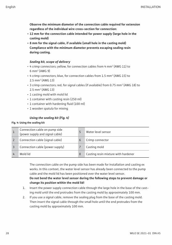
Using the sealing kit (Fig. 4)Fig. 4: Using the sealing kit
1Connection cable on pump side (power supply and signal cable)
5 Water level sensor
2 Connection cable (signal cable) 6 Crimp connector
3 Connection cable (power supply) 7 Casting mold
4 Mold lid 8 Casting resin mixture with hardener
The connection cable on the pump side has been made for installation and casting ex works. In this context, the water level sensor has already been connected to the pump cable and the mold lid has been positioned over the water level sensor. Do not bend the water level sensor during the following steps to prevent damage or change its position within the mold lid!
1. Insert the power supply connection cable through the large hole in the base of the cast-ing mold until the end protrudes from the casting mold by approximately 100 mm.
2. If you use a signal cable, remove the sealing plug from the base of the casting mold. Then insert the signal cable through the small hole until the end protrudes from the casting mold by approximately 100 mm.

Installation and operating instructions Wilo-Actun OPTI-MS... 29
INSTALLATION English
3. Strip 50 mm of the cable sheaths on connection cables and signal cables.4. Cut the individual wires of pump and connection cables to the specified lengths so that
associated, individual wires correspond accordingly.5. Strip the ends of individual wires.6. Connect the individual wires of pump and connection cables using the correspondingly
matching crimp connectors. Check that the connection is secure.7. Add the full quantity of hardener to the casting resin and carefully stir using the en-
closed wooden spatula.8. Bring the casting mold to an upright position (connection cable at the bottom, pump
cable at the top) and secure it in this position so that the casting mold cannot tip over. In this process, do not squeeze the casting mold.
9. Shake the casting resin mixture into the casting mold up to a fill level of approximately 10 mm below the mold opening.
10. Evenly pull the connection cable through the base of the casting mold until the mold lid seals the casting mold. In this process, hold the pump cable and carefully feed it through. Make sure the water level sensor is not pulled into the casting mold when you are pulling through connection cables!
11. Secure the pump cable so that no pressure is applied to the mold lid and it has been positioned evenly on the casting mold.
12. If necessary wipe escaped casting resin from the connection cable.13. Leave the casting resin mixture to harden for a minimum of 3 hours (at ambient tem-
peratures ≥ 16 °C) without moving the casting mold.Once you have completed this step, check that the connections are not damage and check the earthing duct. Measure the resistance between the motor housing / pump and the ground terminal of the cable connection and check that it is below 3 Ω.Once again measure the insulation resistance prior to connecting the connection cables to the switchbox / main switch. This way, you can identify damage caused during installation.
• Use an insulation tester (measuring voltage is 500 V) to measure the resistance of the connection cable and the signal cable (if available).
• The resistance must not fall below the following values during initial commissioning:• Power supply connection cable: min. 100 MΩ,• Signal cable: min. 100 MΩ.If the insulation resistance is too low, it is possible that moisture has penetrated into the cable and/or the motor. Do not connect the pump. Consult the manufacturer!
If the insulation resistance is OK, connect the unit to the mains supply by connecting the connection cables to the switchbox.Electrical connections may only be made by a qualified electrician!

30 WILO SE 2021-01 DIN A5
English INSTALLATION
6.3.2. Wilo-Actun OPTI-MS electrical connection (Fig. 5)
Fig. 5: Wilo-Actun OPTI-MS connection cable
Item Wire color Connection
1 Black Power input for AC or DC (phase/neutral and polarization identified by frequency converter)2 Black
3 Black Water level sensor (already connected)
4 Yellow/green Earthing
5 White Signal cable to directly connect a switch (e.g. float or pressure switch) or Wilo-MS Control; Wires must be short-circuited and insulated if the signal cable is not used!6 Red
6.4. Motor protectionThe motor protection is integrated in the frequency converter:We also recommend installing a residual-current device (RCD).Local and national regulations must be observed when connecting the pump.
6.5. Installation
DANGER: heights! When installing the pump and its accessories, work is sometimes performed directly at the edge of the well or tank. Carelessness and/or wearing inappro-priate clothing may result in a fall. There is a risk of fatal injury! Take all safety precautions to prevent a fall.
Observe during pump installation:• This work must be carried out by qualified personnel and electrical work must be carried
out by an electrician.• The operating space must be clean, free of coarse solids, dry, frost-free and, if neces-
sary, decontaminated. It must also be suitable for the particular pump. There must be sufficient water inflow for the submersible pump’s maximum output in order to prevent dry run and/or air intake.
• When working in tanks, wells or boreholes, a second person must be present for safety reasons. If there is a risk of toxic or asphyxiating gases building up, the necessary pre-cautions must be taken.

Installation and operating instructions Wilo-Actun OPTI-MS... 31
INSTALLATION English
• Ensure that lifting equipment can be set up without any trouble, since this is required for installing and dismantling the pump. It must be possible to reach the pump safely in its operating and storage locations using the lifting equipment. The set-down location must have a solid bearing surface. The lifting gear must be attached to the defined lifting eyes to transport the pump. When using chains, these must be connected to the lifting eyes using a shackle. Lifting gear must be technically approved.
• Connection cables must be routed in such a way that safe operation and easy installa-tion/dismantling are possible at all times. Do not carry or pull the pump by the connec-tion cable. The pump is delivered ex works with a connected connection cable for the power supply and connected signal cables routed in parallel. The power supply connection cable and the signal cable (if used) must be extended to the required length on site prior to installation to suit the available space in the borehole using the enclosed sealing kit (see Section 6.5.1). Check the cable cross-section used and the routing type chosen. Make sure the available cable length is sufficient.
• Observe the corresponding protection class when using switchgear. As a rule, install switchgear overflow-proof.
• Structural components and foundations must be of sufficient stability in order to allow the product to be fixed securely and functionally. The end user or the supplier is respon-sible for the provision of the foundations and their suitability in terms of dimensions, stability, and strength.
• Check that the available consulting documents (installation plans, operating space configuration, feed conditions) are complete and correct.
• Observe all regulations, rules and laws for working with heavy and under suspended loads. Wear appropriate protective clothing!
• Observe the locally applicable accident prevention and safety regulations of profession-al and trade associations.
NOTICE:
• To achieve the necessary cooling, the pump must always be immersed when in operation. Ensure minimum water submersion at all times!
• Do not use an additional non-return valve on the pressure side. This would result in system malfunction.
6.5.1. Vertical pump installationIn this installation method, the submersible pump is installed directly on the ascending pipe. The installation depth is determined by the length of the ascending pipe. In narrow well shafts, a centring device must be used because the pump must not come into con-tact with the walls of the well as this could damage the cable and pump. Use hoisting gear with sufficient bearing capacity.

32 WILO SE 2021-01 DIN A5
English INSTALLATION
The motor must not sit on the bottom of the well as this can lead to tensions and slag-ging of the motor. This would mean that heat dissipation is no longer guaranteed and the motor could overheat.In addition, the pump should not be installed at the same height as the filter pipe. The intake current can draw up sand and solid material, which would mean that the motor cooling is no longer guaranteed. This would also result in increased wear of the hydraulics. To prevent this, it may be necessary to use a cooling shroud or install the pump in the vicinity of unperforated well casings.
Installation with threaded pipesFig. 6: Installation
1 Unit 7 Square timber (2x)
2 Ascending pipe 8 Cable clip
3 Supporting clamp 9 Mounting bracket
4 Lifting equipment LsStatic water level(pump not in operation)
5 Connection cable LdDynamic water level(pump in operation)
6 Minimum submersion
NOTICE: Observe the following prior to installing threaded pipes:
• The threaded pipes must be screwed into each other leak-tight and firmly. To achieve this, wrap the threaded pin with hemp or Teflon tape.
• When screwing in the pipes, make sure that the pipes are aligned (not tilted) to ensure that the thread is not damaged.
• Observe the submersible pump’s direction of rotation and use suitable threaded pipes (right-hand or left-hand thread) so that they do not come loose by themselves.
• Threaded pipes must be secured against inadvertently coming loose.
1. Extend the connection cable installed ex works according to the space available in the borehole. For this purpose, use the enclosed sealing kit to extend by the required length.
2. Fit the first pipe to the pressure connection of the of the pump. Screw together all necessary pipes if only few pipes are required and the lifting equipment has reached a sufficient height.

Installation and operating instructions Wilo-Actun OPTI-MS... 33
INSTALLATION English
3. Fit a mounting bracket to the pressure connection of the respective last pipe and fit a supporting clamp below the flange.Make sure that the cable is not damaged by the supporting clamp. The cable must always be routed outside the supporting clamp!
4. Secure the lifting equipment to the mounting bracket and lift the complete unit.5. Swivel the unit over the borehole and slowly lower it.
Make sure the cable and well walls are not damaged!
6. Route the connection cable along the piping. Always fasten the cable below and above a pipe adaptor using a cable clip.
7. Place two square timbers over the well shaft. Lower the unit until the supporting clamp is resting on the square timbers.
8. If necessary, connect an additional pipe and repeat the process until the pump has been positioned at the required depth.
9. Disassemble the mounting bracket from the pressure pipe and fit the well closure (e.g. well cover) on the discharge pipe.
WARNING: danger of crushing! During installation the entire weight is resting on the lifting equipment and the bearer cable may be subject to tension. This can result in severe crush-ing! Before disassembling the mounting bracket, make sure that the bearer cable is NOT under tension.
10. Fasten the lifting equipment to the well closure and hoist the entire unit (consisting of the pump, piping and well closure).
11. Remove the supporting clamp, square timbers and guide the connection cables to the outside through the well closure.
12. Place the unit on the well and fasten the well closure.13. Fit the pressure pipe to the tap on the well closure and route the connection cables to
the switchbox.

34 WILO SE 2021-01 DIN A5
English INSTALLATION
Installing piping for deep wellsLong piping is needed for deep wells. With lengths of 10 m or more, impermissible bending stress may occur when lifting the piping and it may become damaged.To prevent this, the piping must be installed successively in short lengths.To do this, the individual sections (recommendation: max. 3 m) are lowered into the borehole and installed one after the other. This way, longer piping can be installed for deep wells without any problems.
NOTICE: Metal pressure pipes must be integrated into equi-potential bonding according to the locally applicable regulations and approved rules of technology:
• In this process, make sure the contacts are con-nected across an area that is as large as possible and guarantee a low-resistance connection!
Installing flexible pipingThe pump can also be used with flexible piping (e.g. hoses). In this case, the piping is fitted to the pressure connection and then lowered into the borehole together with the pump.Observe the following in the process:
• Nylon or stainless steel guys are used to lower the pump.• The guy must have sufficient bearing capacity for the complete system (pump, piping,
cable, water column).• The guy must be fastened to the attachment points (eyelets) provided on the pressure
port for that purpose. If these attachment points are not available, an intermediate flange containing suspension points must be installed.
DANGER due to improper fixation. The guy must not be wound around the pressure port or affixed to the piping. This could result in slipping or the piping might become separated. There is an increased risk of injury! Always attach the guy to the specified attachment points!
Installation and operating instructions Wilo-Actun OPTI-MS... 35
INSTALLATION English
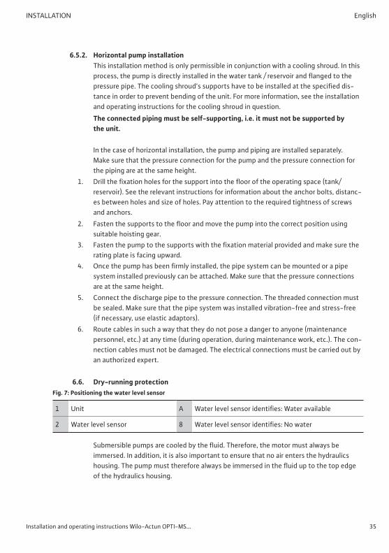
6.5.2. Horizontal pump installationThis installation method is only permissible in conjunction with a cooling shroud. In this process, the pump is directly installed in the water tank / reservoir and flanged to the pressure pipe. The cooling shroud’s supports have to be installed at the specified dis-tance in order to prevent bending of the unit. For more information, see the installation and operating instructions for the cooling shroud in question.The connected piping must be self-supporting, i.e. it must not be supported by the unit.
In the case of horizontal installation, the pump and piping are installed separately. Make sure that the pressure connection for the pump and the pressure connection for the piping are at the same height.
1. Drill the fixation holes for the support into the floor of the operating space (tank/reservoir). See the relevant instructions for information about the anchor bolts, distanc-es between holes and size of holes. Pay attention to the required tightness of screws and anchors.
2. Fasten the supports to the floor and move the pump into the correct position using suitable hoisting gear.
3. Fasten the pump to the supports with the fixation material provided and make sure the rating plate is facing upward.
4. Once the pump has been firmly installed, the pipe system can be mounted or a pipe system installed previously can be attached. Make sure that the pressure connections are at the same height.
5. Connect the discharge pipe to the pressure connection. The threaded connection must be sealed. Make sure that the pipe system was installed vibration-free and stress-free (if necessary, use elastic adaptors).
6. Route cables in such a way that they do not pose a danger to anyone (maintenance personnel, etc.) at any time (during operation, during maintenance work, etc.). The con-nection cables must not be damaged. The electrical connections must be carried out by an authorized expert.
6.6. Dry-running protectionFig. 7: Positioning the water level sensor
1 Unit A Water level sensor identifies: Water available
2 Water level sensor 8 Water level sensor identifies: No water
Submersible pumps are cooled by the fluid. Therefore, the motor must always be immersed. In addition, it is also important to ensure that no air enters the hydraulics housing. The pump must therefore always be immersed in the fluid up to the top edge of the hydraulics housing.

36 WILO SE 2021-01 DIN A5
English COMMISSIONING
In the event of installation of the water level sensor on the ascending pipe, make sure that it is not exposed to water running down the ascending pipe. Use a suitable well cover to protect the ascending pipe from penetrating rainwater!
Automatic restart after dry runThe motor immediately stops if dry-running protection is triggered. The integrated electronics system attempts to restart the motor at 5-minute intervals until correct operating conditions have been re-established.
7. CommissioningThe “Commissioning” section contains all the important instructions for the operating personnel for starting up and operating the pump.The following general conditions must always be met and checked:
• Installation type, including cooling (does a cooling shroud have to be installed?)• Minimum water submersion / Max. immersion depth
These general conditions must also be checked after a long period without opera-tion, and any defects detected must be repaired!
Always keep this manual either by the pump or in a place specially reserved for it, where it is accessible for the entire operating personnel at all times.In order to prevent damage or serious injury when commissioning the pump, the follow-ing must be observed:
• Commissioning of the pump may only be carried out by qualified and trained personnel in accordance with the safety instructions.
• All persons working on or with the pump must have received, read, and understood this operating and maintenance manual.
• All safety devices and emergency cut-outs must be connected and checked to ensure that they work properly.
• Electrical and mechanical adjustments must be made by qualified personnel.• The pump is suitable for use under the specified operating conditions.
In general, people must be kept out of the working area of the pump. No persons are allowed in the work area during start-up or operation.
• Make sure a second person is present at all times when you are working in wells and tanks. Adequate ventilation must be ensured if there is danger of toxic gases forming.

Installation and operating instructions Wilo-Actun OPTI-MS... 37
COMMISSIONING English
7.1. Electrical systemConnection of the pump and installation of the connection cable as described in the “Installation” section and in accordance with the applicable national guidelines and regulations (for example the VDE guidelines in Germany).
• The pump must be properly protected and earthed.• Ensure all monitoring devices are connected and have been tested.• A power supply separator (main switch or DC switch for operation with photovoltaics
systems) must be provided on site!
RISK of fatal injury due to electrocution! Improper electrical connections can lead to fatal electrical shocks. Electrical connections may only be carried out by a qualified electrician approved by the local energy supply company, in accordance with locally applicable regulations.
Direction of rotation controlThe direction of rotation is controlled via the integrated frequency converter. It in-ternally guarantees correct polarity and the pump automatically rotates in the correct direction.
7.2. Initial commissioningCheck the following prior to initial commissioning:
• The pump was installed and connected correctly.• Insulation check was carried out.• For applications in closed pipe systems:
The system has been vented and flushed.
7.2.1. Venting the pump and piping (for closed pipe systems)• Open all slide valves in the pressure pipe.• Switch on the power supply (main switch or DC switch, see Section 6.5). Depending
on the available supply voltage (mains operation or solar power supply) the pump now operates at maximum delivery rate.The air escapes through the corresponding air vent valves. If air vent valves have not been installed, check the taps so the air can escape here!
• Once the pump and pipe system have been vented, once again disconnect the pump from the power supply and close any potentially open taps.

38 WILO SE 2021-01 DIN A5
English COMMISSIONING
7.3. Operation
7.3.1. Before switching onCheck the following prior to switching on the submersible pump:
• Proper and secure cable routing (e.g. no loops)• Firm fit of all components (pump, piping, etc.)• Operating conditions:
• Fluid temperature• Immersion depth
• Open all the gate valves in the pressure pipe. The pump must not be switched on when the slide valves are throttled or closed.
7.3.2. Switching on• Switch on the power supply (main switch or DC switch, see Section 6.5). If the supply
voltage is available, the pump automatically switches on and off as per the operating conditions.
7.3.3. After having switched on
Behavior during mains operationAfter having switched on the power supply, the integrated frequency converter starts up the pump to its maximum speed and the pump supplies at full power.The rated current is briefly exceeded during the start-up procedure. Once the start-up procedure has completed, the operating current may no longer exceed the rated current.If the motor does not start immediately after the pump is switched on, immediately disconnect the power supply. The start pauses specified in the “Technical data” section must be observed before starting up again. If the fault recurs, the unit must be switched off again immediately. The pump must only be restarted once the fault has been rectified.
Behavior under solar power supplyAfter having switched on the power supply and as soon as the minimum voltage re-quired to operate the motor has been generated, the frequency converter starts up the pump. Depending on the available power provided by the solar panels, the frequency converter generates the maximum available speed. If the voltage drops below the required minimum value, the frequency converter switch-es off the pump.

Installation and operating instructions Wilo-Actun OPTI-MS... 39
DECOMMISSIONING/DISPOSAL English
7.4. Conduct during operationWhen operating the pump, always follow the locally applicable laws and regulations for work safety, accident prevention, and handling electrical machinery. Operators must clearly specify staff activities to guarantee safe operating processes. All personnel is responsible for ensuring that regulations are observed.The pump is equipped with moving parts. During operation, these parts rotate in order to pump the fluid. Certain substances in the fluid can result in very sharp edges forming on the moving parts.
WARNING: rotating parts! The rotating parts can crush and sever limbs. Do not reach into the hydraulics or touch the rotating parts when the machine is in operation. Switch off the pump and allow the rotating parts to come to a standstill prior to maintenance and repair work!
The following must be checked at regular intervals:• Operating voltage (permissible deviation +/- 5 % of the rated voltage)• Frequency (permissible deviation +/- 2 % of the rated frequency)• Current consumption (permissible deviation between phases is a maximum of 5 %)• Switching frequency and switching pauses (see technical data)• Minimum water submersion• Quiet and low-vibration running• Gate valves in the pressure pipe must be open.
8. Decommissioning/DisposalAll work must be carried out with the greatest care.Proper protective clothing is to be worn.When carrying out work in wells and/or tanks, the respective local protection measures must be observed in all cases. A second person must be present for safety reasons.Auxiliary lifting devices in technically perfect condition and officially certified lifting gear must be used to lift and lower the pump.
RISK of fatal injury due to malfunction! Lifting gear and lifting devices must be in a perfect technical condition. Work may only commence if the lifting device has been checked and found to be in perfect working order. If it is not inspected, fatal injuries may result!

40 WILO SE 2021-01 DIN A5
English DECOMMISSIONING/DISPOSAL
8.1. Temporary shutdownFor this type of shutdown, the pump remains installed and is not cut off from the elec-tricity supply. In the event of temporary shutdown the pump must remain completely immersed so that it is protected from frost and ice. Ensure that the temperature of the fluid and in the operating space does not fall below +3 °C.This ensures that the pump is always ready for operation. For extended downtime, a regular (monthly to quarterly) 5 minute test run should be carried out.
CAUTION! Only perform test runs under the proper operating and usage conditions. Never run the machine dry! Failure to observe this provision can lead to irrepa-rable damage!
8.2. Shutdown for maintenance work or storage• Switch off the system and secure it against being switched on again by unauthorized
persons.• Have a qualified electrician disconnect the pump from the mains.• Close the slide valves in the pressure pipe after the well cover.
You can then begin disassembly.
CAUTION: beware of burns! Housing parts may heat up to well above 40 °C during operation. There is a risk of burns! After switching it off, let the pump cool down to ambient temperature.
8.2.1. RemovalIn the case of vertical installation, disassembly takes place in the same way as installation:
• Disassemble the well cover.• Dismantle the ascending pipe and unit in the reverse order to installation.
When configuring and selecting lifting equipment make sure that it is adequate to lift the entire weight of piping, pump including connection cables and water column!
When installed horizontally the water tank / reservoir must be drained completely. Thereafter the pump can be released from the pressure pipe and disassembled.
8.2.2. Return delivery / StorageFor shipping, the parts must be packed in tear-proof plastic bags of sufficient size in such a manner that they are tightly sealed and leak proof. The parts may only be shipped by forwarding agents who have been instructed appropriately.Please also refer to the “Transport and storage” section.
Installation and operating instructions Wilo-Actun OPTI-MS... 41
DECOMMISSIONING/DISPOSAL English
8.3. RecommissioningBefore recommissioning, the submersible pump must be cleaned of contaminants.The submersible pump can then be installed and put into operation in accordance with the specifications in this operating and maintenance manual.The submersible pump may only be switched on again if it is in proper working order.
8.4. Disposal
8.4.1. Operating fluidsOils and lubricants must be collected in appropriate containers and properly disposed of in accordance with EC Directive 75/439/EEC as well as in compliance with the provisions of sections 5a and 5b of the German Waste Act (AbfG) or the applicable local laws.Water-glycol mixtures have been categorized as water-polluting class 1 in accordance with VwVwS 1999. When disposing of the unit, adhere to DIN 52 900 (for propanediol and propylene glycol) and/or local guidelines.
8.4.2. Protective clothingProtective clothing worn for cleaning and maintenance work is to be disposed of in accordance with the German Waste Code TA 524 02 and EC Directive 91/689/EEC.
8.4.3. Information on the collection of used electrical and electronic productsProper disposal and appropriate recycling of this product prevents damage to the envi-ronment and dangers to your personal health.
NOTICE: Disposal in domestic waste is prohibited! In the European Union, this symbol may have been included on the product, the packaging or the accom-panying documentation. It means that the electrical and electronic products in question must not be disposed of along with domestic waste.
To ensure proper handling, recycling and disposal of the used products in question, please note the following points:
• Only hand over these products at designated, certified collecting points.• Observe the locally applicable regulations!
Please consult your local municipal authority, the nearest waste disposal site, or the dealer who sold the products to you for information on proper disposal. For further information on recycling, go to www.wilo-recycling.com.

42 WILO SE 2021-01 DIN A5
English MAINTENANCE AND REPAIR
9. Maintenance and repairAny repairs to the motor or replacement of the motor filling must be carried out by Wilo customer service only.
10. TroubleshootingIn order to prevent damage or serious injury when repairing malfunctions on the unit, observe the following:
• Attempt to remedy a fault only if you have qualified staff available. This means that each job must be carried out by qualified personnel. For example, electrical work must be performed by a trained electrician.
• Always secure the unit against an accidental restart by disconnecting it from the mains. Take appropriate safety precautions.
• Always have a second person on hand to ensure the unit is switched off in an emergency.
• Secure moving parts to prevent injury.• Unsanctioned modifications to the unit are made at the operator’s own risk and release
the manufacturer from any warranty obligations.
10.1. Faults
10.1.1. Fault: The unit will not start or only starts after a delay1. Electricity supply interrupted, short-circuit or earth fault in the connection cable and/or
motor winding• Have the motor and wires checked by a specialist and replaced if necessary• Check the error messages on the frequency converter
2. With solar power operation: Solar panels do not generate sufficient power• Check the alignment of the solar panels and correct if necessary• Check solar panels for dirt and clean if necessary• In the event of an insufficient exposure to the sun as a result of the time of day or
cloudy skies, switch over to mains operation or a generator or wait for the weather conditions to improve
3. Fuses, the motor protection switch, and/or monitoring devices were triggered• Have a specialist inspect the connections and correct them as necessary• Install and set motor protection switches and miniature circuit breakers according to
the technical instructions, reset monitoring devices• Check that the impeller runs freely. If necessary clean it and ensure it runs freely again

Installation and operating instructions Wilo-Actun OPTI-MS... 43
TROUBLESHOOTING English
10.1.2. Fault: Unit is running but not pumping1. No fluid available
• Check fluid level or inlet, if necessary open slide valve• Clean the supply line, slide valve, suction piece, suction port, or suction strainer• During standstill, the pressure pipe drains; check the pipework for leakage and the
non-return valve for contaminants; remedy errors2. Impeller blocked or impaired movement
• Switch off the unit, secure it against being switched back on again and free the impeller
3. Defective piping• Replace faulty parts
10.1.3. Fault: The unit runs, but not within the specified operating values1. Inlet blocked
• Clean the supply line, slide valve, suction piece, suction port, or suction strainer2. Impeller blocked or impaired movement
• Switch off the unit, secure it against being switched back on again and free the impeller
3. Air in the system• Vent the system
4. Defective piping• Replace faulty parts
5. Inadmissible levels of gas in the fluid• Consult the manufacturer
6. Excessive decrease in the water table during operation• Check the system’s supply and capacity
10.1.4. Fault: The unit does not run smoothly and is noisy1. Suction port, suction strainer, and/or impeller clogged
• Clean the suction port, suction strainer, and/or impeller2. Impeller stiff
• Switch off the unit, secure it against being switched back on again and free the impeller
3. Inadmissible levels of gas in the fluid• Consult the manufacturer
4. Signs of wear• Replace worn parts
5. Defective motor bearing• Consult the manufacturer
6. Unit is installed under tension• Check installation, use rubber expansion joints if necessary
44 WILO SE 2021-01 DIN A5
English APPENDIX
10.1.5. Further steps for troubleshootingIf the points listed here do not rectify the fault, contact customer service. They will be able to help you in the following ways:
• Telephone or written support from customer service• On-site support from customer service• Inspection or repair of the unit at the factory
Please note that you may be charged for some services provided by our customer ser-vice. For more details, please contact customer service.
11. Appendix
11.1. Spare partsSpare parts can be ordered from the manufacturer’s customer service. Provide the serial and/or article numbers to avoid return queries and incorrect orders.
Subject to change without prior notice.


WILO SEWilopark 1D-44263 DortmundGermanyT +49(0)231 4102-0F +49(0)231 [email protected] for You
Local contact atwww.wilo.com/contact