oil shale and coal combustion inside a fluidized bed … · certain amount of organic matter under...
TRANSCRIPT
Abstract—Oil shale, as well as, solid fuels like coal and wood
ships is used in fluidized bed technology for a wide range of applications. The characteristics of fluidized bed combustion using sand as bed materials with particles diameter of 0.6 - 1.18 mm were studied experimentally. An experimental test rig has been designed and manufactured to produce a good fluidization in a wide range of operating conditions. Cold experiments were carried before performing hot experiments to predict the suitable initial bed height, which has been seen to be 3-cm. LPG fuel, has been used as a gaseous fuel. The effects of bed material on gas temperature distribution along the combustor height are investigated and presented in the present work. The combustion of oil shale and coal in fluidized bed combustor were verified by adding a continuous flow rates with reducing the quantities of LPG. The photos of the bed in cold and hot states are presented. The results show the great dependent of the parameters under study on the bed characteristics and solid fuel combustion.
Keywords—Fluidized Bed, Oil shale, Sand, Gaseous fuels, Coal, Wood ships.
I. INTRODUCTION IL shale is commonly defined as a fine-grained sedi¬mentary rock containing organic matter that yields
substantial amounts of oil and combustible gas upon destructive distil¬lation. Most of the organic matter is insoluble in ordinary organic solvents; therefore, it must be decomposed by heat¬ing to release such materials. Underlying most definitions of oil shale is its potential for the economic recovery of energy, including shale oil and combustible gas, as well as a number of byproducts. A deposit of oil shale having economic poten¬tial is generally one that is at or near enough to the surface to be developed by open-pit or conventional underground mining or by in-situ methods [1-4]. The oil shale is any compact laminated sedimentary rock with more than 33% ash which is capable of yielding a certain amount of organic matter under a suitable process. The main positive sides of the large-scale use of oil shale are the security of supply for the state energy sector and the relative price independence from the world market. The negative sides are great environmental damage due to mining and use of oil shale and low calorific value of oil shale [5-7].
Classification of Oil Shale: There are varying
*Ibrahim I. A., Shabaan M. M, And Gad H. M. are Mechanical Power Engineering Dept., Faculty of Engineering, Port Said University, Port Said, Egypt. (corresponding author’s phone: +201220252531; fax: ; e-mail:[email protected] ).
classifications of oil shales depending on their mineral content, type of Kerogen, age, depositional history, and organisms from which they are derived. The age of the oil shale deposits ranges from Cambrian to Tertiary age. Lithologies range from shales to marl and carbonate rocks, all of which form a mixture of tightly bound organic and inorganic materials. Oil shales have been divided into three categories based on mineral composition – carbonate-rich shale, siliceous shale and cannel shale. Carbonate-rich shales derive their name from the large amount of carbonate minerals such as calcite and dolomite. As many as twenty carbonate minerals have been found in oil shale, the majority of which are considered authigenic or diagentic. Carbonate-rich oil shales, particularly that of lacustrine-sourced deposits, have usually the organic-rich layers sandwiched between carbonate-rich layers. These deposits are hard formations that are resistant to weathering and they are difficult to process using ex-situ methods. Siliceous oil shales are usually dark brown or black shales. They are not rich in carbonates but rather in siliceous minerals such as quartz, feldspar, clay, chert and opal [8].
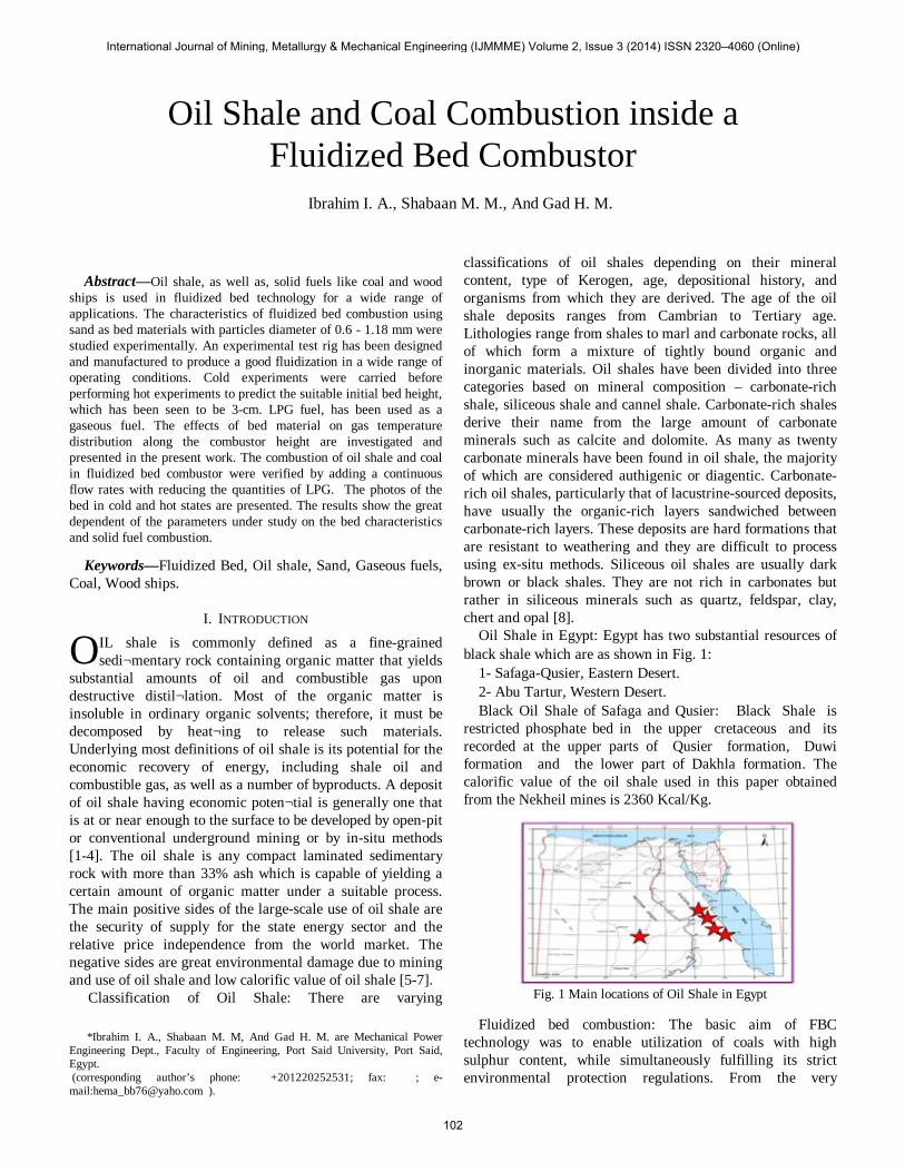
Oil Shale in Egypt: Egypt has two substantial resources of black shale which are as shown in Fig. 1:
1- Safaga-Qusier, Eastern Desert. 2- Abu Tartur, Western Desert. Black Oil Shale of Safaga and Qusier: Black Shale is
restricted phosphate bed in the upper cretaceous and its recorded at the upper parts of Qusier formation, Duwi formation and the lower part of Dakhla formation. The calorific value of the oil shale used in this paper obtained from the Nekheil mines is 2360 Kcal/Kg.
Fig. 1 Main locations of Oil Shale in Egypt
Fluidized bed combustion: The basic aim of FBC
technology was to enable utilization of coals with high sulphur content, while simultaneously fulfilling its strict environmental protection regulations. From the very
Oil Shale and Coal Combustion inside a Fluidized Bed Combustor
Ibrahim I. A., Shabaan M. M., And Gad H. M.
O
International Journal of Mining, Metallurgy & Mechanical Engineering (IJMMME) Volume 2, Issue 3 (2014) ISSN 2320–4060 (Online)
102

beginning, work focused on the development of large boilers, mainly for utility electric energy production. A fluidized-bed (FB) is obtained by passing a fluid at a sufficient rate up through a mass of solid particles held in a (often cylindrical) vessel. As the name indicates, the action of passing the fluid up through the mass of particles causes it to take on fluid like Properties [9]. Fluidized bed powder: Geldart [10] classified powders into four groups according to their fluidization properties at ambient conditions. The Geldart Classification of Powders is now used widely in all fields of powder technology. The fluidization properties of a powder in air may be predicted by establishing in which group it lies. heat transfer in fluidized-bed combustors is better than any combustion system because the heat transfer by radiation from solid particles [9]. It is important to note that at operating temperature and pressures above ambient a powder may appear in a different group from that which it occupies at ambient conditions. This is due to the effect of gas properties on the grouping and may have serious implications as far as the operation of the fluidized bed is concerned [11-13].
II. EXPERIMENTAL SET UP Test rig: The apparatus used is a vertical combustor which is first fed with combustible mixture (LPG and Air) from the bottom through a distributor plate, which is consists of numerous nozzles (50 nozzles each has 7 holes with 2 mm diameter). The combustor is filled by sand particulates for limited height. The initial height of the bed determined from cold tests. These particulates are the fluidization medium. The particulates diameters lay in the range of (0.6:1.18 mm). Fig.2 shows the schematic diagram of the apparatus.
1- Gas bottle 2- Pressure regulator 3- Orifice meter 4- U-tube manometer 5- Gas distributor 6- Distributor plate 7- Glass window 8- Cooling water out 9- Flame trap 10- U -tube manometer 11- Orifice meter 12- Air duct 13- Control valve 14- Air blower
Fig. 2 Experimental test rig and combustor The combustor is a vertical cylindrical steel tube of 213 mm diameter and 1200 mm height. The combustor is
surrounded by a cylindrical water jacket for cooling. The combustor contains one vertical side, 10 tapping holes of 19 mm diameter arranged axially along the combustor to measure any desired phenomena, and it has a glass window to see the fluidization in cold and hot states. There are two feeding cones on the top, one for solid fuels (wood ships and coal). The other cone is for making-up the fluidized-bed particulates. Fig. 2 shows the combustor details. The combustion air is admitted from a centrifugal air blower to the combustor through a 4˝ steel pipe. The air mass flow rate was controlled by gate valve. The combustion air flow rate is measured by means of a calibrated orifice meter, which is connected to a U-tube water manometer. The gaseous fuel flows from a pressurized gas cylinder, with LPG at about 3 bar. The fuel flow rate is measured by means of a calibrated orifice meter before entering the mixing chamber. Distributor plate, the aim of the distributor plate is to ensure that the mixture distributed across the area of the bed uniformly. The distributor diameter is 190 mm. The distributor plate consists of 50 nozzles; each nozzle has 7 holes with 2 mm diameter each. Six holes are distributed radially and one axially. The nozzles are distributed in a radial manner with equal distance along the cross section area of the distributor. Fig. 3 shows the distributor plate and nozzles.
Fig. 3 Distribution plate and nozzles
Flame trap The idea of flame trap is to prevent the combustion wave to reach the mixing chamber where the gaseous fuel and oxidant are mixed and being explosive. The flame trap composed of multi copper tube, which quenches the flame wave by increasing the cooling area, which is presented, by circumertial area of the tube.
Crushing machine The crushing machines, which have been used for crushing the oil shale and coal, named as Los Angeles, Fig. 4 shows the preparing of solid fuel to combustion, The machine consists of a rolled steel drum having an inside diameter of 711 mm and internal length 508 mm, the drum is rotated by a speed of between 30 and 33 R.P.M The motor, controls and drum are mounted on a robust steel frame together with steel tray for unloading the specimen. The unit is supplied complete with a set of 12 abrasive charges. In the present work a fine wire thermocouple of Platinum - 6 % Rahdium Vr. Platinum - 30 % Rahdium of 0.3 mm in diameter is used for gas temperature measurements at some sections inside
International Journal of Mining, Metallurgy & Mechanical Engineering (IJMMME) Volume 2, Issue 3 (2014) ISSN 2320–4060 (Online)
103
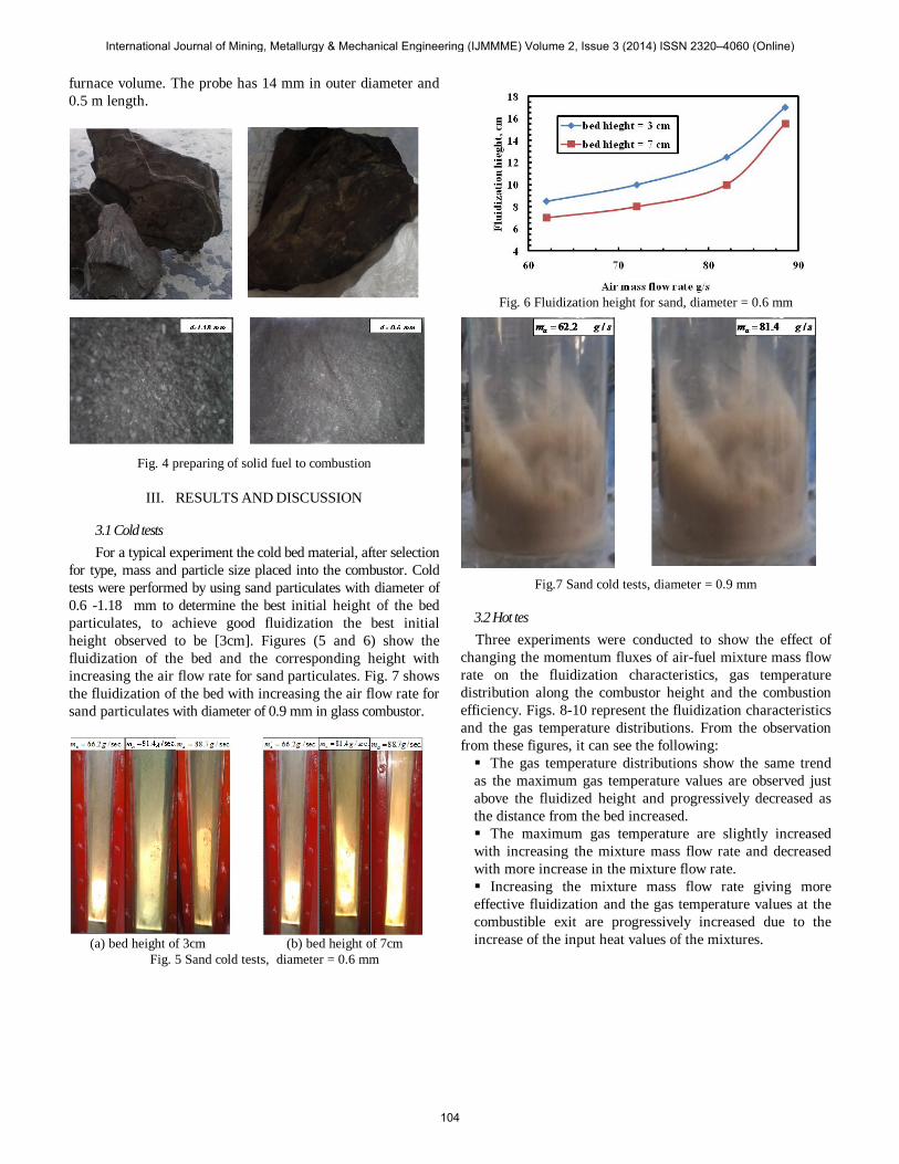
furnace volume. The probe has 14 mm in outer diameter and 0.5 m length.
Fig. 4 preparing of solid fuel to combustion
III. RESULTS AND DISCUSSION
3.1 Cold tests For a typical experiment the cold bed material, after selection for type, mass and particle size placed into the combustor. Cold tests were performed by using sand particulates with diameter of 0.6 -1.18 mm to determine the best initial height of the bed particulates, to achieve good fluidization the best initial height observed to be [3cm]. Figures (5 and 6) show the fluidization of the bed and the corresponding height with increasing the air flow rate for sand particulates. Fig. 7 shows the fluidization of the bed with increasing the air flow rate for sand particulates with diameter of 0.9 mm in glass combustor.
(a) bed height of 3cm (b) bed height of 7cm
Fig. 5 Sand cold tests, diameter = 0.6 mm
Fig. 6 Fluidization height for sand, diameter = 0.6 mm
Fig.7 Sand cold tests, diameter = 0.9 mm
3.2 Hot tes Three experiments were conducted to show the effect of
changing the momentum fluxes of air-fuel mixture mass flow rate on the fluidization characteristics, gas temperature distribution along the combustor height and the combustion efficiency. Figs. 8-10 represent the fluidization characteristics and the gas temperature distributions. From the observation from these figures, it can see the following: The gas temperature distributions show the same trend as the maximum gas temperature values are observed just above the fluidized height and progressively decreased as the distance from the bed increased. The maximum gas temperature are slightly increased with increasing the mixture mass flow rate and decreased with more increase in the mixture flow rate. Increasing the mixture mass flow rate giving more effective fluidization and the gas temperature values at the combustible exit are progressively increased due to the increase of the input heat values of the mixtures.
International Journal of Mining, Metallurgy & Mechanical Engineering (IJMMME) Volume 2, Issue 3 (2014) ISSN 2320–4060 (Online)
104

Fig. 8 Gas temperature distribution along combustor height (a) and a photo for fluidized bed (b) Fuel: LPG, m.
f = 1.3 g/s, m.a =24 g/s.
diameter = 0.6 mm
Fig. 9 Gas temperature distribution along combustor height (a) and a photo for fluidized bed (b) Fuel: LPG, m.f = 1.3
g/s, m.a =24 g/s. diameter = 0.9 mm
Fig.10 Gas temperature distribution along combustor height (a) and a photo for fluidized bed (b) Fuel: LPG, m.f = 1.3
g/s, m.a =52.5 g/s. diameter = 0.6 mm
Before adding the solid fuel the oil shale and coal crashed using crushing machine to get a suitable size of particulates to combustion, see Fig. 4. A set of experiments were carried out using a crashed oil shale and coal of particle
diameter ranging from 0.6 - 1.18 mm) with using reduced quantities of LPG fuel. The solid fuels are continuously fed by using a particle feeder to the combustor. Figs.11-13 shows the combustion of different kinds of the solid fuel with the sand bed material. It could prove the ability of the experiment test rig to fire any kind of the solid fuels by using the fluidization techniques [14]. In hot tests, the LPG fuel was burned with sand as bed materials. The experiments were conducted to show the effect of momentum flux of air-fuel mixture mass flow rate on the fluidization characteristics.
.sec/24
.sec/3.1shale oilWithout
gmgm
a
LPG
=
=⋅
⋅
.sec/24
.sec/1shale oilWith
gmgm
a
LPG
=
=⋅
⋅
.sec/24
.sec/6.0shale oilWith
gmgm
a
LPG
=
=⋅
⋅
.sec/24
.sec/0.0shale oilWith
gmgm
a
LPG
=
=⋅
⋅
Fig. 11 The combustion steps of oil shale for sand diameter of 0.6
mm
.sec/24
.sec/3.1shale oilWithout
gmgmLPG
=
=⋅
⋅
.sec/24
.sec/1shale oilWith
gmgm
a
LPG
=
=⋅
⋅
.sec/24
.sec/6.0shale oilWith
gmgm
a
LPG
=
=⋅
⋅
.sec/24
.sec/0.0shale oilWith
gmgm
a
LPG
=
=⋅
⋅
Fig. 12 The combustion steps of oil shale for sand diameter of 0.9
mm
Fig. 13 The combustion steps of coal for sand diameter of 0.9 mm
0
10
20
30
40
50
60
70
80
500 600 700 800 900 1000 1100
Hie
ght,
cm
Gas temperature,°C
0
10
20
30
40
50
60
70
80
500 600 700 800 900 1000 1100 1200Gas temperature, °C
Hie
ght,
cm
0
10
20
30
40
50
60
70
80
500 600 700 800 900 1000
Hie
ght,
cm
Gas temperature,°C
International Journal of Mining, Metallurgy & Mechanical Engineering (IJMMME) Volume 2, Issue 3 (2014) ISSN 2320–4060 (Online)
105

IV. CONCLUSION A series of experiments have been conducted out for a cylindrical fluidized bed combustor using sand with (0.6 - 1.18 mm) as bed materials and LPG as gaseous fuel; carry information on the combustion process. Based on the information and data presented, the following findings were obtained: For cold tests: • Increasing the momentum flux the bed height increased. • The bed height in 0.6 mm sand is greater than the bed height
in 1.18 mm sand. • Increasing the initial bed height the fluidization height decrease. For hot tests: • The bed height in hot tests is greater than cold tests for the
same conditions. • When increasing the momentum flux the average temperature
increase due to the greater amount of fuel burnt. • The temperature difference between the lower section
and the higher section decrease. • When increasing the air mass flow rate the average temperature
decrease. • The ability design of the experimental test rig to fire any
kind of the solid fuels by using the fluidization techniques.
REFERENCES [1] Yavuzkurt, S., Gutfinger, C. and Dayan, J., “Fluidization”, John Wiley
and Sons, New York, Vol. 143, (1979). [2] Hammad, M., Zurigat, Y., Khzai, S., Hammad, Z. and Mubydeem,
O.,”Fluidized bed combustion unit for oil shale”, International Oil Shale Conference: “Recent Trends in Oil Shale”, Amman, 7-9 November (2006).
[3] Dyni, J. R., “Geology and Resources of Some World Oil-Shale Deposits”, Oil Shale, Vol. 20, pp.193– 252,(2003).
[4] Altun, N. E., Hicyilmaz, C., Hwang, J. Y., Suatbagci, A. Kok, M. V., “Oil Shales in The world and Turkey; Reserves, Current Situation and Future Prospects: A review”, Oil Shale, Vol. 23, pp.211– 227,(2006).
[5] Veski, R., Palu, V. and Kruusementr. K., “Co-Liquefaction of Kukersite Oil Shale and Pine Wood in Supercritical Water”, Oil Shale, Vol. 23, pp.238 248, (2008).
[6] Sensoz, S., Putun, E. and Kockar, O. M., “Liquid products from pyrolysis of synthetic blends of Turkish oil shales and lignites”, Energy Sources, Vol. 22, pp. 751–761, (2000).
[7] Gavin, J. M. “Oil Shale”, Washington, etc., (1924). [8] Hutton, A.C., “Petrographic classification of oil shales”, International
Journal of Coal Geology, Vol. 8, pp. 203–231, (1987), [9] Simeon, N. O., “Fluidized bed combustion”, Marcel Dekker, Inc. (2004). [10] Geldart D., “The design of distributors for gas-fluidized beds”, Powder
Technology, Vol. 42 pp. 67-78(1985). [11] Baron, J. Bulewicz E.M., Zukowsk, W. Kandefer S. and Pilawska
M.,”Combustion of hydrocarbon fuels in a bubbling fluidized bed”, Combustion and Flame Vol.128 pp 410–421(2002).
[12] Wang L., Wu P. and Ni X., “Combustion of liquid petroleum gas in a fluidized bed furnace with a jetting-mixing distributor”, Powder Technology, Vol.170, pp.8693, (2006).
[13] Zukowski W.,” Acoustic effects during the combustion of gaseous fuels in a bubbling fluidized bed”, Combustion and Flame, Vol.117, pp. 629–635, (1999).
[14] Shabaan, M.M.,” Effect of bed material type on combustion efficiency of fluidized bed combustor” ERJ, Vol.33, pp.97-109, (2010).
International Journal of Mining, Metallurgy & Mechanical Engineering (IJMMME) Volume 2, Issue 3 (2014) ISSN 2320–4060 (Online)
106