oi psqx03 eng 1 - avintos
TRANSCRIPT

Version 2017/05/08 ©2017 PS Automation GmbH
Subject to changes!
Operating Instructions PSQx03

2
Contents
Type key ............................................................................................................................................................................ 2
1. Symbols and safety ....................................................................................................................................................... 3
2. Usage as per specification ............................................................................................................................................. 4
3. Storage .......................................................................................................................................................................... 4
4. Operational conditions ................................................................................................................................................. 4
4.1 Installation position ................................................................................................................................................ 5
5. Function ........................................................................................................................................................................ 5
6. Manual operation ......................................................................................................................................................... 6
7. Valve mounting ............................................................................................................................................................. 7
8. Setting the mechanical stops ........................................................................................................................................ 7
8.1 Adjustment of the position indicator ...................................................................................................................... 8
9. Setting the position switches ........................................................................................................................................ 8
10. Setting the torque limit ............................................................................................................................................... 9
11. Electric supply ........................................................................................................................................................... 10
11.1 Wiring diagram .................................................................................................................................................... 10
12. Commissioning .......................................................................................................................................................... 12
13. Service/maintenance ................................................................................................................................................ 12
13.1 Cleaning ............................................................................................................................................................... 12
13.2 Spare parts .......................................................................................................................................................... 13
14. Appendix ................................................................................................................................................................... 13
14.1 Accessories .......................................................................................................................................................... 13
14.2 Declaration of Incorporation of Part Completed Machinery and
EC Declaration of Conformity in compliance with the Directives on EMC and Low Voltage ..................................... 14
Type key
example
PSQ203 / 400VAC / 50-60Hz / 64W / 250Nm / 28
Actuator type
Voltage supply
Frequency
Max. input power
Torque
Operating speed [s/90°]

3
1. Symbols and safety Dangers of non-compliance with safety regulations PSQx03 actuators are built to state-of-the-art technology and are safe to operate. Despite this, the actuators may be
hazardous if operated by personnel that has not been sufficiently trained or at least instructed, and if the actuators
are handled improperly, or not used as per specification.
This may
• cause danger to life and limb of the user or a third party,
• damage the actuator and other property belonging to the owner,
• reduce safety and function of the actuator.
To prevent such problems, please ensure that these operating instructions and the chapter on "1. Symbols and
safety" in particular have been read and understood by all personnel involved in the installation, commissioning,
operation, maintenance and repair of the actuators.
Basic safety notes • The actuators may only be operated by skilled and authorized operating personnel.
• Make sure to follow all security advices mentioned in this manual, any national rules for accident prevention, as
well as the owner´s instructions for work, operation and safety.
• The isolating procedures specified in these operating instructions must be followed for all work pertaining to the
installation, commissioning, operation, change of operating conditions and modes, maintenance, inspection,
repair and installation of accessories.
• Before opening the actuator cover, ensure that mains supply is isolated and prevented from unintended re-
connection.
• Areas that can be under voltage have to be isolated before working on them.
• Ensure that the actuators are always operated in faultless condition. Any damage or faults, and changes in the
operational characteristics that may affect safety, must be reported at once.
Danger signs The following warning symbols are used in this manual:
Caution! There is a general risk of damage to health and/or properties.
Danger! Electrical voltages may be present that are dangerous to life!
There is a risk of damage to health and/or properties with danger to lives.
With power supply 24 VAC the open motor phase can produce voltages up to 35 V due to motor
generated induction voltage.

4
Other notes • The motor surface may have elevated temperature when servicing, inspecting or repairing it immediately after
operation. Danger of burning the skin!
• Always observe the relevant operating instructions when fitting PS accessories or operating the actuator with
PS accessories.
• Connections for signal in- and output are double isolated from circuits that can be under dangerous voltage.
2. Usage as per specification • The PSQx03 quarter turn actuators are exclusively designed as electric valve actuators. They are meant to be
mounted on valves for motor operation.
• Any other use is considered to be not in accordance to standard specification, and the manufacturer cannot be
held liable for any damage resulting from it.
• The actuators may not be used outside the limits laid out in data sheets, catalogues and order documentation.
Otherwise the manufacturer cannot be held liable for any resulting damage.
• Usage as per specification includes the observance of the operating, service and maintenance conditions laid
down by the manufacturer.
• Not to be regarded as usage as per specification are mounting and adjustment of the actuator, and servicing.
Special precautions have to be taken while doing this!
• The actuators may only be used, serviced and repaired by personnel that are familiar with them and informed
about potential hazards. The specific regulations for the prevention of accidents have to be observed.
• Damages caused by unauthorized modifications carried out on the actuators are excluded from the
manufacturer's liability.
• Supply voltage may be switched on only after properly closing the main cover or terminal box.
3. Storage The following must be observed with regards to proper storage:
• Only store the actuators in ventilated, dry rooms.
• Store the actuators on shelves, wooden boards etc. to protect them from soil moisture.
• Cover the actuators with plastic foil to protect them from dust and dirt.
• Protect the actuators against mechanical damage.
4. Operational conditions • The standard actuators can be operated at ambient temperatures from -20°C to +80°C
• Ambient temperature range for modulating duty is from -20°C to +60°C.
• The operating modes correspond to IEC 60034-1, 8: S2 for 3-point operation, and S4 for control duty (see data
sheet for specific values for each actuator type).
• For protection against moisture and dust, the actuator enclosure rating is IP67 according to EN 60529. To ensure
the protection rating, the cover must be fitted correctly and the holding screws tightened crosswise. The cable
glands must be suitable for the cables and correctly fitted to the actuator.
• When installing the actuators, leave enough space to permit cover removal (figure 1).
• Any installation position is allowed except "cover pointing downwards" (figure 2).

5
Figure 1: Installation dimensions
Dimensions A B C D E F G H I
PSQ103 267 161 128 104.5 237 158 241 111 125
PSQ203 355 228 194 122.5 307 185 289 109 200
PSQ503/703 416 240 198 171.5 358 235 337 128 200
PSQ1003/1503 416 240 198 171.5 289 235 362 128 250
4.1 Installation position
Outdoor usage
When using actuators in environments with high temperature
fluctuations or high humidity, we suggest a heating resistor to be
fitted to prevent the build-up of condensation within the enclosure.
Figure 2: Installation position
5. Function The electric quarter-turn actuators series PSQx03 are designed to operate valves with 90° motion. The PSQ actuators
are provided with a mechanical interface according to ISO 5211 for valve mounting. The motor torque is transmitted
via a spur gear onto the sun wheel of a „Wolfrom“-gear. The rotating output wheel of the „Wolfrom“-gear holds a
removable drive bush to connect the actuator with the valve stem. Two adjustable position switches are limiting the
electrical motion in both directions by interrupting the motor current or control circuit when reaching the adjusted
position.
The 90° motion is mechanically adjustable by +/- 5° by means of two stop screws. Torque switches are installed for
each direction (at PSQ103 and bigger).

6
The handwheel does allow comfortable manual operation in case of power failure or for commissioning. The
handwheel is idle when the motor is operating the actuator, but engaged in any position without clutching or
declutching.
Electrical wiring is done to a terminal block under the actuator cover.
6. Manual operation
Figure 3: Handwheel assembly
The handwheel does provide manual operation in case of power failure or commissioning. It is idle when the motor
is operating and always ready for operation without clutching or declutching.
Figure 4: Manual operation
The actuators are supplied with a loosely enclosed
handwheel. Mount the handwheel according to
figure 3.
Do not exceed the adjusted electrical
stroke limits by handwheel.
The mechanical limits must be set
accordingly.
Failure to observe this warning will change
the electrical feedback setting!

7
7. Valve mounting The PSQx03 actuators are provided with a mechanical interface according to ISO 5211 for valve mounting. The
„Wolfrom“ gear contains a removable drive bush to connect the actuator to the valve stem.
1 = actuator flange
2 = drive bush
3 = indicator tooth
4 = marking hole
• Ensure that the mechanical dimensions of the valve flange
and the valve shaft suits the actuator flange (1).
• The inner contour of the drive bush (square, round bore with
keyway, double-D) must correspond to the valve shaft. The
drive bush (2) has an indicator tooth (3) or a marking hole (4)
which clearly defines the position of the drive bush. There
also is a corresponding marking at the actuator (recess or
coloured marking). The tooth may be filed off, if appropriate.
• Clean all surfaces of the connection area, slightly lubricate
drive bush and valve shaft.
• Insert drive bush into the actuator first. Ensure that the
marking of the drive bush and the actuator correspond to
each other.
• Position the actuator on the valve. Tighten the screws in a
diagonal sequence with the required torque.
For valve mounting please ensure that the cover of the actuator is always closed in order to avoid
that components inside the actuator are damaged.
8. Setting the mechanical stops There are two adjustable screws installed for setting the mechanical limit of the 90° motion.
When setting the mechanical end positions, only the handwheel may be used. Do not operate the
actuator electrically.
• Remove the protection cap (figure 6, item 3) from either stop screw.
• Unscrew both hexagon sockets anti-clockwise by approximately 5 turns.
• Move the actuator to the closed position by turning the handwheel clockwise.
Turn stop screw for closed position (figure 6, item 1) to the stop.
• Move the actuator to the open position by turning the handwheel anti-clockwise.
Turn stop screw for open position (figure 6, item 2) to the stop.
• Screw back protective caps (figure 6, item 3).
Item 1: Stop screw CLOSED position
Item 2: Stop screw OPEN position
Item 3: Protective caps
Figure 6: Mechanical stops
Figure 5: Actuator flange
4

8
8.1 Adjustment of the position indicator
The position indicator is a two-coloured half ball turning
under a transparent dome with blackened quarter segments.
Take off the cover and turn the half ball as appropriate to
adjust the position indicator.
9. Setting the position switches
Figure 8: Setting the switching cams for position switches
The standard position switches serve to switch off the motor when the desired limits are reached.
Additional position switches are potential-free opening/closing contacts and serve to indicate the valve position.
They are available as accessories. The switches are activated by cams. These cams are stepless adjustable on their
shaft by means of a friction coupling.
Item 1: Switching cam CLOSE position
Item 2: Switching cam OPEN position
Item 3: Bridge for screw driver support
NOTE:
Use the bridge (figure 8, item 3) as support for the screw driver when adjusting the cams.
Ensure that the mains supply is secured against accidental switching-on!
Figure 7: Adjustment of the position indicator
3
2 1

9
• Run the actuator electrically to the closed position until the valve is closed and the actuator is switched off by the
torque switch.
• Turn the cam of the CLOSE position switch (figure 8, item 1) with an isolated screw driver (4 mm blade width)
anti-clockwise until the micro switch is heard to click.
• Run the actuator electrically to the open position until the valve is fully open and the actuator is switched off by
the torque switch.
• Turn the cam of the OPEN position switch (figure 8, item 2) with an isolated screw driver (4 mm blade width)
clockwise until the micro switch is heard to click.
• Drive the actuator away from either end position to release the stop screws.
• Turn both stop screws counter-clockwise by one turn.
• Replace protection caps (figure 6, item 3) onto the stop screw holes after setting the position switches.
10. Setting the torque limit There is one torque switch installed for each direction that cuts off the motor current when operated (single phase
motors).
The quarter-turn actuator is set and checked by the manufacturer in order to limit the actuator to the nominal
torque in both directions. The reduction of the maximum output torque is possible by setting the switch brackets, to
suit the specific requirements of the valve.
• Loosen the torque setting screws (fig. 9,
item 3) and turn the switch brackets to the
required position.
• Fix this positions by tightening the screws.
Item 1: Switch bracket „CLOSE“
Item 2: Switch bracket „OPEN“
Item 3: Fixing screws
Figure 9: Brackets holding the switches
There are marks on both switch brackets.
When moving those marks against the center
of the set screw, the following torque
adjustments can be achieved (Figure 10).
Figure 10: Torque setting (shown at mark 4)
1 3
2
1
2
3
4
5 6
1
2
3 4
5 6

10
11. Electric supply
Before connecting to mains, ensure that the mains supply is isolated and secured against an
accidental switching-on.
The mains connecting cables must be suitably dimensioned to accept the maximum current requirement of the
actuator, and correspond to IEC 227 and IEC 245. The yellow-green coloured cables may only be used for connecting
to earth.
When inserting the cable through the cable connector, ensure that the maximum bending radius for the cable is
observed.
The PSQx03 electric actuators do not have an internal electrical power switch. Therefore, a power mains switch has
to be provided for installation. It should be positioned close to the device and be easily accessible to the user and
shall be labelled as the mains isolator switch for the actuator.
Electric installation as well as over-current and overvoltage protection devices must be conform to the standard DIN
IEC 60364-4-41, protective class I resp. protection class 3 (24 VAC/24 VDC) and also to the standard DIN IEC 60364-
4-44 according to the applied overvoltage category of the actuator.
Please protect all of the power supply and control cables in front of
the terminals mechanically by using suitable measures against
unintentional loosening. Never install the power supply and the
control cables together in one line but instead please always use
two different lines.
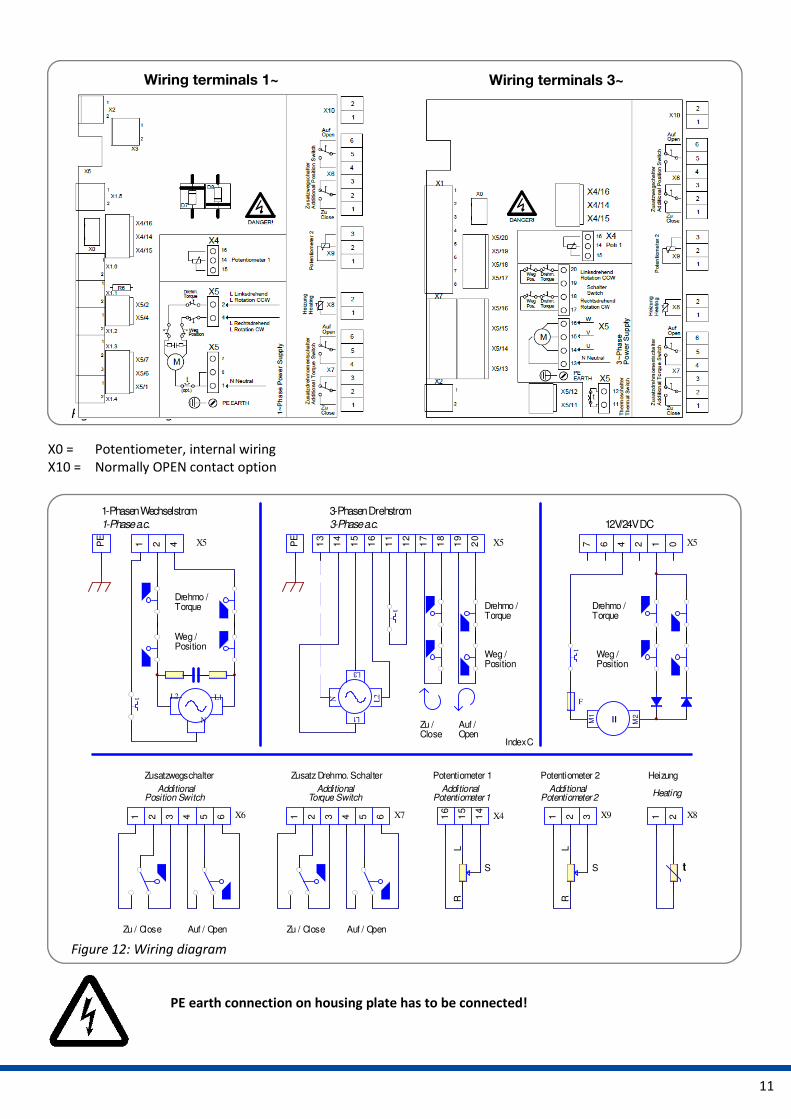
11.1 Wiring diagram
Figure 12 indicates the wiring diagrams for standard actuators. However, the wiring diagram inside the actuator
cover is relevant for the specific actuator. See the separate wiring diagram in the corresponding service instructions
for any set of accessories.
PSQ103 PSQ203 PSQ503 PSQ703/1003
Mark Torque Mark Torque Mark Torque Mark Torque
End position 100% End position 100% End position 100% End position 26100%2
Mark 1 90% Mark 1 85% Mark 1 90% Mark 1 -
Mark 2 80% Mark 2 70% Mark 2 80% Mark 2 85%
Mark 3 70% Mark 3 55% Mark 3 70% Mark 3 -
Mark 4 60% Mark 4 - Mark 4 60% Mark 4 -
Mark 5 50% Mark 5 - Mark 5 50% Mark 5 50%
Mark 6 Mark 6 Mark 6 Mark 6
11
Figure 11: Wiring terminals
X0 = Potentiometer, internal wiring
X10 = Normally OPEN contact option
Figure 12: Wiring diagram
PE earth connection on housing plate has to be connected!
Wiring terminals 1~ Wiring terminals 3~
31 2 4 65 X6
LR
S
Potentiometer 1
Potentiometer 1Additional
Zusatzwegschalter
Additional
12V/24V DC
Zu / Close Auf / Open
Position Switch
14
15
16
X4
13
14
15
16
11
12
17
18
19
20
X5
LR
S
Potentiometer 2
Potentiometer 2Additional
1 2 3 X9
Weg / Position
t
PE
L3
L1
L2
N
1 2 4 X5PE
N
L2 L1t
3-Phasen Drehstrom1-Phasen Wechselstrom
1 2 X8
Heizung
Heating
t
Weg / Position
3-Phase a.c.1-Phase a.c.
Index C
Zu / Close
Auf /Open
M2
M1
=
F
t
012467 X5
Drehmo / Torque
Weg / Position
Drehmo / Torque Drehmo /
Torque
31 2 4 65 X7
Zusatz Drehmo. Schalter
Additional
Zu / Close Auf / Open
Torque Switch

12
Figure 13: Electrical connection PE
Two adjustable position switches are installed to limit the stroke of the actuator, and cut-off the motor current in
the relative direction.
Most motors have a thermal switch, depending on the actuator type, to cut off the current in both directions when a
maximum temperature is reached (only at standard single phase power supply).
12. Commissioning • Close the cover.
• Turning the handwheel, drive the valve to the middle position.
• Switch the setting signal briefly to OPEN and CLOSE and check that the actuator operates in the correct
direction. If necessary, reverse the setting signal for OPEN/CLOSE.
• Drive the actuator in either direction, using the setting signal until the position switch cuts-off. Check that the
position switch setting is correct. If necessary re-adjust the position switch (see chapter 9).
With power supply 24 VAC the open motor phase can produce voltages up to 35 VAC due to
motor generated induction voltage.
13. Service/maintenance The actuators are maintenance-free if used under the operating conditions as established in the data sheet. The
gearboxes are lubricated for life and do not require further lubrication.
Caution !
During maintenance and repair the actuator must not be operated
electrically.
13.1 Cleaning
The actuators should be cleaned with dry cloth.

13
13.2 Spare parts
PSQx03 actuators are very robust functional units. In case of malfunction or damage of any component, spare parts
are available as per a separate spares price list. Please contact PS Automation GmbH or the appropriate
representative.
Damaged actuators can be returned to our plant in Bad Dürkheim, Germany, or to our representatives, for
evaluation of failures and repair.
14. Appendix
14.1 Accessories
Various accessories are available in order to adapt the actuator to the various installation conditions. The following
shows a short selection.
Please see the actuator data sheets for technical data. Operating and installation instructions are available
separately for each accessory. We will be pleased to assist you with advice also by telephone.
• = available
)1 = PSAP with external relay required
)2 = only to be used with reversing starter contactor
)3= supply voltage 24 V or 115-230 V
For additional position and torque switches:
Standard switches with silver contacts are suitable for currents 100 mA to 5 A at voltages in the
range of 24 V to 230 V AC/DC. For lower power up to 0,12 VA (0,1 mA to 100 mA at 1 V to 24 V
AC/DC) we recommend switches with gold contacts (2WE Gold and 2DE Gold).
With power supply 24 VAC the open motor phase can produce voltages up to 35 V due to motor
generated induction voltage.
Acc
ess
ori
es/
op
tio
ns
Power supply 230 VAC 1~ 115 VAC 1~ 24 VAC 1~ 400 V 3~ 24 VDC
Position signal
switches 2WE • • • • •
Position signal
switches gold
2WE
Gold • • • • •
Add'l torque switches 2DE • • • • •
Add'l torque switches
gold
2DE
Gold • • • • •
Positioner PSAP • • )1 • )1 • )2
Position transmitter PSPT • • • • •
Heating resistor HR • • • •)3 •
Potentiometer PD • • • • •
Reversing starter
contactor WSM01 •
Corrosion protection K2 Corrosion protection K2 incl. heating resistor
Enclosure IP67 IP IP68 incl. heating resistor and corrosion protection K2

14
14.2 Declaration of Incorporation of Part Completed Machinery and EC Declaration of
Conformity in compliance with the Directives on EMC and Low Voltage

15

16
Hong Kong
MaxAuto Company Ltd.
Room 2008, 20/F., CCT Telecom Building
11 Wo Shing Street
Fotan, Shatin, Hong Kong
Tel.: <+852> 26 87-50 00
Fax: <+852> 81 01-37 43
eMail: [email protected]
www.maxonicauto.com
China
Shenzhen Maxonic Automation
Control Co., Ltd.
Maxonic Automation Control Mansion
No. 3 Lang Shan Road, Hi-Tech Industrial Park,
Shenzhen, Guangdong, PRC.
518057
Tel.: <+86> 755 86 25 03 88
Fax: <+86> 755 86 25 03 74
eMail: [email protected]
www.maxonicauto.com
India
PS Automation India Pvt. Ltd.
Srv. No. 25/1, Narhe Industrial Area,
A.P. Narhegaon, Tal. Haveli, Dist.
IND-411041 Pune
Tel. : <+ 91> 20 25 47 39 66
Fax : <+ 91> 20 25 47 39 66
eMail : [email protected]
www.ps-automation.in
Great Britain
IMTEX Controls Ltd.
Unit 5A, Valley Industries,
Hadlow Road
GB-Tonbridge, Kent TN11 0AH
Tel.: <+44> (0) 17 32-85 03 60
Fax: <+44> (0) 17 32-85 21 33
eMail: [email protected]
www.imtex-controls.com
Italy
PS Automazione S.r.l.
Via Pennella, 94
I-38057 Pergine Valsugana (TN)
Tel.: <+39> 04 61-53 43 67
Fax: <+39> 04 61-50 48 62
eMail: [email protected]
Spain
Sertemo, S.L.
Pol. Ind. Alba - Avda. Generalitat 15
Apartado de Correos, 142
E-43480 Vila-Seca (Tarragona)
Tel. : <+34> 9 77 39 11 09
Fax : <+34> 9 77 39 44 80
eMail : [email protected]
www.sertemo.com
PS Automation GmbH
Gesellschaft für Antriebstechnik
Philipp-Krämer-Ring 13
D-67098 Bad Dürkheim
Tel.: +49 (0) 63 22 - 60 03 – 0
Fax: +49 (0) 63 22 - 60 03 – 20
eMail: [email protected]
www.ps-automation.com