ohio.usatf.orgohio.usatf.org/.../0ea8ac78-3211-4b84-81ad-66024fe5e775.docx · web viewwhen...
TRANSCRIPT
The Proposed USATF Guide to Electro-Optical Distance Measuring
(EDM)
The sport of athletics relies on the measurement of performance bytime and distance.

Introduction
Philip Kissum in his book, Surveying Practice, defines surveying as “the art, science and technology of making such measurements as are necessary to determine the relative position of points above, on or beneath the surface of the earth, or to establish such points in a specified position.” The key terms in the above definition are art, science, technology and measurements.
As Lord Kelvin (after whom a unit of temperature is named) said: “When you measure what you are speaking about and express it in numbers, you know something about it, but when you cannot express it in numbers your knowledge is of a meagre and unsatisfactory kind... “

A HISTORY OF MEASUREMENT
1791, Paris
The French National Assembly agrees to standardize the meter as one ten-millionth part of a quarter of the Earth’s circumference. As no-one knows exactly how long this is, various people set off to find out. Unfortunately, France fixes its official standard of length before all the results are in and as a result the standard meter bar is a fifth of a millimeter too short. This also means the circumference of the Earth (through the poles) is a bit more than the forty million meters everyone was expecting it to be.
1799, ParisThe metric system is set up, through the adoption of two platinum/iridium alloy standards: a meter length and a kilogram mass.
1824, LondonAn act of Parliament introduces an improved and more widespread system of measurements, and an imperial standard yard is constructed. The yard is placed in the Houses of Parliament for safe keeping – which doesn’t turn out to be all that safe after all when they burn down in 1834. After this, a new standard yard bar is made and kept in a fireproof box, which is then bricked up in a wall in the new House of Commons and only taken out every 20 years to check the lengths of standard copies.
1875, ParisSeventeen nations sign the Convention of the Metre, and the International Bureau of Weights and Measures is set up.
1955, Teddington, EnglandThe first accurate atomic clock is built by Louis Essen (1908-1997) at the National Physical Laboratory (NPL). It keeps time to better than one millionth of a second per day.
1960, USAThe first working laser is constructed by Theodore Maiman (1927–2007) in California. Initially a discovery in search of an application, it rapidly becomes essential to the accurate measurement of time, length and luminous intensity.
1960The International System of Units (SI System) is established, including units of mass, length, time, temperature, current and luminous intensity.
Electronic Distance MeasuringApplicable Standards: Australia: Regulation 80 of the National Standard Measurement Act 1960

MEASUREMENTS IN TRACK AND FIELD
IAAF COMPETITION RULES 2014-2015
RULE 137Measurement Judge (Scientific)
One (or more) Measurement Judge(s) shall be appointed when Electronic or Video Distance Measurement or other scientific measurement device is to be used.Before the start of the competition, he will meet the technical staff involved and familiarise himself with the equipment. Before each event, he will supervise the positioning of the measuring instruments, taking account of the technical requirements given by the manufacturer and the instrument calibrating laboratory. To ensure that the equipment is operating correctly, he shall, before and after the event, supervise a set of measurements in conjunction with the Judges and under the supervision of the Referee (and if possible, the ITOassigned to the event), to confirm agreement with results achieved using a calibrated certified steel tape. A form of conformity shall be issued and signed by all those involved in the test and attached to the results card. During the competition he shall remain in overall charge of the operation. He will report to the Field Events Referee to certify that the equipment is accurate.
RULE 148Measurements
For Track and Field Events in competitions under Rules 1.1(a), (b), (c) and (f), all measurements shall be made with a calibrated certified steel tape or bar or with a scientific measuring device. The steel tape, bar or scientific measuring device shall have been certified by the IAAF and the accuracy of the measuring equipment used in the competition shall have been verified by an appropriate organisation accredited by the national measurement authority, such that all measurements can be traced back to national and international measurement standards.
SECTION X - WORLD RECORDSRULE 260
World Records
26. For World Records in Field Events:(a) The performances shall be measured either by three Field Judges using a calibrated and certified steel tape or bar or by an approved scientific measuring apparatus, the accuracy of which has been confirmed by a qualified Measurement Judge.
2014 USATF Competition Rules
RULE 123TECHNICAL MANAGER
The Technical Manager shall be responsible for: 1. Ensuring that the track, runways, circles, arcs, sectors, landing areas for field events and all equipment are in accordance with the Rules and shall verify the calibration of electronic measuring equipment. Certification of such shall be made to the appropriate Referee prior to the commencement of the competition.
RULE 137ELECTRONIC MEASUREMENT JUDGE
1. One or more Measurement Judges shall be appointed when technological or scientific distance measurement is to be used. 2. Before the meet, this Judge shall meet with the technical staff and the operators of electronic distance measuring and data recording devices to become familiar with the specific equipment and the personnel. 3. Before each event where the device is used, the Judge shall supervise the positioning of the measuring instruments, taking account of the technical requirements given by the manufacturer, the instrument calibration specifications and the needs of the event chief. 4. To ensure that the equipment is operating correctly, the Judge shall, before and after each event, personally supervise or conduct a set of measurements in conjunction with the equipment operator under the supervision of the Referee to verify the accuracy of the device against a known distance, such as certified steel tape or an independently certified distance such as 100m. A form of conformity shall be issued, signed by all those involved in the test and attached to the results card. 5. During the competition the Judge shall remain in overall charge of the operators and equipment operation so that the Judge can report to the Field Events Referee that the equipment is accurate and operating properly during the competition.
RULE 148MEASUREMENTS AND WEIGHTS
1. All measurements, except as otherwise herein provided, must be made with a certified steel tape, fiberglass tape, bar graduated in centimeters, or a certified electronic measuring device. Measurements made with fiberglass tapes shall not be acceptable for records. In the case of a record, see the procedures in Rule 264.
REQUIREMENTS FOR THE USE OF EDM IN TRACK AND FIELD

1. Certified EDM Measurement JudgeAccording to current IAAF and USATF rulebooks the use of EDM is to be monitored and supervised by a qualified EDM Measurement Judge. For USATF, that person is a grade 3 EM official.
2. Calibrated and certified EDM device
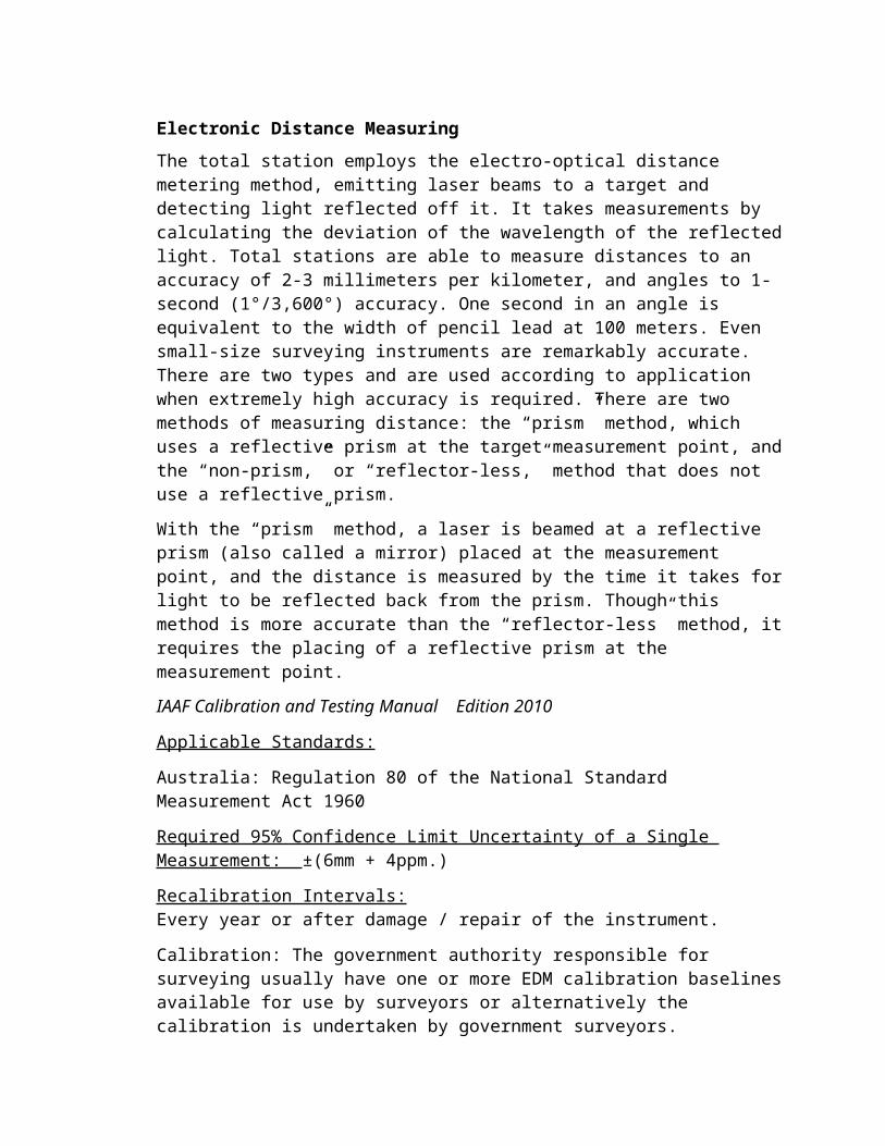
Electronic Distance Measuring
The total station employs the electro-optical distance metering method, emitting laser beams to a target and detecting light reflected off it. It takes measurements by calculating the deviation of the wavelength of the reflected light. Total stations are able to measure distances to an accuracy of 2-3 millimeters per kilometer, and angles to 1-second (1°/3,600°) accuracy. One second in an angle is equivalent to the width of pencil lead at 100 meters. Even small-size surveying instruments are remarkably accurate. There are two types and are used according to application when extremely high accuracy is required. There are two methods of measuring distance: the “prism” method, which uses a reflective prism at the target measurement point, and the “non-prism,” or “reflector-less,” method that does not use a reflective prism.
With the “prism” method, a laser is beamed at a reflective prism (also called a mirror) placed at the measurement point, and the distance is measured by the time it takes for light to be reflected back from the prism. Though this method is more accurate than the “reflector-less” method, it requires the placing of a reflective prism at the measurement point.
IAAF Calibration and Testing Manual Edition 2010
Applicable Standards:
Australia: Regulation 80 of the National Standard Measurement Act 1960
Required 95% Confidence Limit Uncertainty of a Single Measurement: ±(6mm + 4ppm.)
Recalibration Intervals:Every year or after damage / repair of the instrument.
Calibration: The government authority responsible for surveying usually have one or more EDM calibration baselines available for use by surveyors or alternatively the calibration is undertaken by government surveyors.
Notes for federations: Off the shelf EDM are supplied to an industry maximum standard deviation of ±(3mm + 2ppm). A multiplying factor of 2.0 has been used above to convert the standard deviation to a 95% confidence limit. This is a simple interpretation of the ISO Guide to the Expression of Uncertainty of Measurement.

Total Station CalibrationIAAF Calibration and Testing Manual Edition 2010
Before each competition your EDM should be:• Checked for any obvious damage• Checked for horizontal angle measurement accuracy by:
1. Bisecting a clear object about 100m away and record the horizontal angle.2. Change face and bisect the same object and record the horizontal angle.3. The difference between the readings should be 1800 00’ 00” ± the
manufacturer’s tolerance.
• Check for vertical angle measurement accuracy by:1. Bisecting a clear object about 100 m away and record the vertical angle.2. Change face and bisect the same object and record the vertical angle.3. The difference between the readings should be 3600 00’ 00” ± the
manufacturer’s tolerance.
3. Certified and Calibrated Steel Tape
Steel tapes are a basic means of measuring field event performances in athletics. Evenwhen electronic distance measuring (EDM) is used the accuracy of the EDM measurement is checked using a calibrated certified steel tape. The IAAF has relied on its federations to have the accuracy of the steel tapes used certified by an appropriate Weights and Measure Authority (IAAF Rule 148). Nowhere is it stated what the accuracy of the calibration should be.
IAAF Calibration and Testing Manual Edition 2010
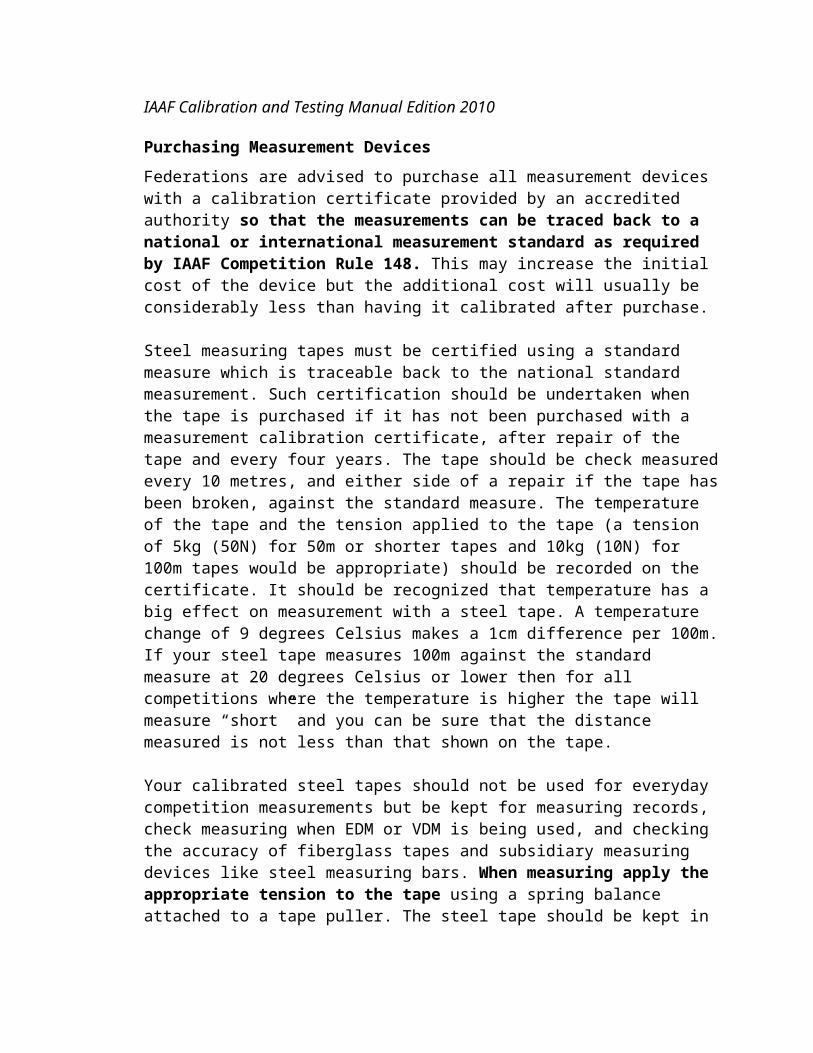
Purchasing Measurement Devices
Federations are advised to purchase all measurement devices with a calibration certificate provided by an accredited authority so that the measurements can be traced back to a national or international measurement standard as required by IAAF Competition Rule 148. This may increase the initial cost of the device but the additional cost will usually be considerably less than having it calibrated after purchase.
Steel measuring tapes must be certified using a standard measure which is traceable back to the national standard measurement. Such certification should be undertaken when the tape is purchased if it has not been purchased with a measurement calibration certificate, after repair of the tape and every four years. The tape should be check measured every 10 metres, and either side of a repair if the tape has been broken, against the standard measure. The temperature of the tape and the tension applied to the tape (a tension of 5kg (50N) for 50m or shorter tapes and 10kg (10N) for 100m tapes would be appropriate) should be recorded on the certificate. It should be recognized that temperature has a big effect on measurement with a steel tape. A temperature change of 9 degrees Celsius makes a 1cm difference per 100m.
If your steel tape measures 100m against the standard measure at 20 degrees Celsius or lower then for all competitions where the temperature is higher the tape will measure “short” and you can be sure that the distance measured is not less than that shown on the tape.
Your calibrated steel tapes should not be used for everyday competition measurements but be kept for measuring records, check measuring when EDM or VDM is being used, and checking the accuracy of fiberglass tapes and subsidiary measuring devices like steel measuring bars. When measuring apply the appropriate tension to the tape using a spring balance attached to a tape puller. The steel tape should be kept in a cool place and only brought outside when a measurement is to be taken so as to minimize temperature errors.
The effect of having a different pull to that used in the tape calibration is quitesubstantial. For a typical steel tape the difference could be about 2.7mm per 10N for a 100m length. As the pull tension used by athletics officials is likely to be less than the calibration tension of 100N the effect is always to over measure the distance.
Also there is a temperature effect of 1.15mm for a 100m length per degree C different from 20°C for a carbon steel tape. Thus it will be seen that the tape pull is likely to have a more significant effect than temperature.
By comparison a manufacturer's standard deviation for an EDM is 3mm + 2ppm. The95% confidence limit for such an instrument measurement is 6mm + 4ppm whichindicates that EDM is inherently more accurate than a steel tape especially over longerdistances.
The calibration services of the National Institute of Standards and Technology (NIST) are designed to help the makers and users of precision instruments achieve the highest possible levels of measurement quality and productivity. NIST provides Calibration Services using well-characterized, stable and predictable measurement processes. NIST calibrates instruments and devices that are metrologically suitable as reference or transfer standards. Merely having an instrument or artifact calibrated at NIST is not enough to make the measurement result traceable to reference standards developed and maintained by NIST. To establish traceability to such reference standards, there must be an unbroken chain of comparisons and each provided measurement must be accompanied by a statement of uncertainty . The measurement system by which values are transferred must be clearly understood and under control. The dates and details of each link in the chain must also be provided.
NIST certified tapes are very expensive. A 30m NIST certified tape will cost over $400 and a 100m tape will cost around $700. 30m steel tapes that are ‘traceable to NIST’ are available for around $80 and can be ordered at: www.mcmaster.com/#graduated-tape-rules/=uizyg1
4. USATF Certified EM Official

HOW TO MAKE A MEASUREMENTBefore making a set of measurements, do you know:
what the measurements are for, and hence the uncertainty of measurement you are seeking?
how many times you should repeat the measurement? the acceptance criteria (the tolerance, for example) for the result?
Are you confident you will be: making the right measurements? using the right tools? involving the right people? carrying out regular reviews? able to demonstrate consistency? following the right procedures?
Has every measuring instrument you intend to use: been calibrated as and when needed? been kept in appropriate conditions, not misused, or damaged (in which case it should
be checked and if necessary calibrated)?Will the instrument:
be checked before the measurements begin?In planning your measurements, have you assessed and minimized the effects of:
instrument performance limitations? the object to be measured? operator skill level? the environment?
Measurements are always made using an instrument of some kind. A measurement tells us about a property of something. The result of a measurement is normally in two parts: a number and a unit of measurement, e.g. 2 meters.’
Uncertainty of measurement is the doubt that exists about the result of any measurement. Youmight think that well-made rulers, clocks and thermometers should be trustworthy, and give the right answers. But for every measurement - even the most careful - there is always a margin of doubt. In everyday speech, this might be expressed as ‘give or take’ ... e.g. a stick might be two meters long ‘give or take a centimeter’. We might say that the length of a certain stick measures 20 centimeters plus or minus 1 centimeter, at the 95 percent confidence level. This result could be written: 20 cm ±1 cm, at a level of confidence of 95%.
It is important not to confuse the terms ‘error’ and ‘uncertainty’.Error is the difference between the measured value and the ‘true value’ of the thing beingmeasured. Uncertainty is a quantification of the doubt about the measurement result.
Many things can undermine a measurement. Flaws in the measurement may be visible orinvisible. Because real measurements are never made under perfect conditions, errors anduncertainties can come from:
The measuring instrument - instruments can suffer from errors including bias, changesdue to ageing, wear, or other kinds of drift, poor readability, noise (for electricalinstruments) and many other problems.
‘Imported’ uncertainties - calibration of your instrument has an uncertainty which is then built into the uncertainty of the measurements you make. (But remember that the uncertainty due to not calibrating would be much worse.)
Operator skill - some measurements depend on the skill and judgement of the operator. One person may be better than another at the delicate work of setting up a measurement, or at reading fine detail by eye. The use of an instrument such as a stopwatch depends on the reaction time of the operator. (But gross mistakes are a different matter and are not to be accounted for as uncertainties.)
The environment - temperature, air pressure, humidity and many other conditions canaffect the measuring instrument or the item being measured.
What is not a measurement uncertainty?
Mistakes made by operators are not measurement uncertainties. They should not be counted as contributing to uncertainty. They should be avoided by working carefully and by checking work.
Tolerances are not uncertainties. They are acceptance limits which are chosen for a process or aproduct.
Specifications are not uncertainties. A specification tells you what you can expect from aproduct. It may be very wide-ranging, including ‘non-technical’ qualities of the item, such as itsappearance.
How to reduce uncertainty in measurement
Always remember that it is usually as important to minimize uncertainties as it is to quantifythem. There are some good practices which can help to reduce uncertainties in makingmeasurements generally. A few recommendations are:
Calibrate measuring instruments (or have them calibrated for you) and use the calibration corrections which are given on the certificate.
Make corrections to compensate for any (other) errors you know about. Make your measurements traceable to national standards - by using calibrations which
can be traced to national standards via an unbroken chain of measurements. You can place particular confidence in measurement traceability if the measurements are quality-assured through a measurement accreditation.
Choose the best measuring instruments, and use calibration facilities with the smallestuncertainties.
Check measurements by repeating them, or by getting someone else to repeat them from time to time, or use other kinds of checks. Checking by a different method may be best of all.

Check calculations, and where numbers are copied from one place to another, check this too.
Be aware that in a successive chain of calibrations, the uncertainty increases at every step of the chain.
Procedure for Measuring Distances on site:
- The zero or some convenient graduation is held against one point- The tape is straightened and pulled taut- The distance is read directly on the tape at the second point
Common Mistakes in Taping:
The error that occurs most frequently is to misread the tape:
- To help detect errors, long distances should be measured in both directions- A good way of checking short distances is to take a second measurement but to use different parts of the tape- Because it is difficult to use the end loop a false zero of 100 mm or 1 m is often used when taping- Great care is needed when doing this to avoid mistakes occurring- Take approximate readings using the end loop as zero and then take a more precise measurement with a false zero
Tape End LoopsTapes come with differing end loops, the claw end being the most common.Attention should be paid to where the zero mark is on a tape to avoid errors.
TensionThis correction is only used with steel tapes. Because steel is elastic the length of a tape will vary according to how much tension is applied to it, steel tapes are often calibrated using a

tension of 50 N. To improve the precision of measurement the tape should be pulled using this standard tension, to ensure this is done properly a spring balance is attached to the tape.
All measurements are based on the same approach and have been helpfully boiled down to six guiding principles.
1. The right measurements
A measurement is made for a reason, and that reason needs to be clearly defined and understood if the measurement is to be a good one. This is of course especially important when the measurement is being carried out for someone else.
2. The right tools
The measuring instruments used need to be appropriate for the task, in a good state of repair, and calibrated – and they need to be used according to the instructions of their owner or manufacturer.
3. The right people
Whoever makes the measurement (sometimes referred to as the ‘operator’) needs to havereceived the right instructions and training. For complex measurements, this training will ofteninclude formal qualifications.
4. Regular review
Measuring instruments are often easily damaged and their performance frequently changes astime passes, so they need to be checked. These checks should be carried out at regular intervalsrather than just before they are needed, to avoid delays. Since many individual instruments may be involved in making a measurement (to check environmental conditions, for instance), a written schedule is usually essential. In many cases this schedule will include both internal checks and less frequent external assessments.
5. Demonstrable consistency

A measurement result isn’t much use if it’s only valid at the place where the measurement is made. For highly accurate measurements, there are often all sorts of local factors that need to be taken into account if this is to be avoided. The force of gravity, for example, varies by up to 1% from place to place on the Earth’s surface (and changes with time too, as a result of the shifting gravitational influences of the Sun and Moon, among other things). In turn, this affects the weights of objects (as measured, for example, by spring balances). So, an assessment of such factors should be made in planning an important measurement. What happens next depends on the outcome of the assessment – it may be that the factors are too small to significantly affect the uncertainty of the results, or that they can be corrected for by the user, given appropriate data and instructions, or that it may be that the result should be quotedwith higher uncertainty.
6. The right procedures
As there are so many factors which need to be addressed to ensure that the result of a measurement is a good one, it’s important that important or complex measurements are carried out in accordance with written procedures. Though these might simply be the documents supplied by the manufacturer, these may not be sufficient, especially where a number of different pieces of equipment are involved. An important function of a written procedure is to safeguard health and safety, so it will often be backed up by a risk assessment for this purpose.
How Accurate is World Class Accurate?
ISO 17123-5 Total Station Field Test Work Flow.
Introduction: ISO 171123-5 is a field procedure. It is designed to verify that the operator and instrument can meet the accuracy requirement in the actual on site environment with 95% confidence.
IAAF Suggestion in “Notes for federations: Off the shelf EDM are supplied to an industry maximum standard deviation of ±(3mm + 2ppm). A multiplying factor of 2.0 has been used above to convert the standard deviation to a 95% confidence limit. This is a simple interpretation of the ISO Guide to the Expression of Uncertainty of Measurement.”The requested world standard measurement accuracy is 6mm +/- 4ppm or 6.4 mm at 100 meters.
Work Flow using MLM and a standard Hammer/Discus sector. Using MLM generates the same line length data and reduces the workload that a coordinate system (COGO) measurement requires. The location of the Instrument Stations does not require coordinate measurements.
Short test (single line)
Test Field Setup
1. Set two target points (T1, T2) as indicated in Figure 1. The targets should be firmly fixed on to the ground. The distance between the two target points should be set longer than the average distance (e.g. 60 m) according to the intended measuring task. Their heights should be as different as the surface of the ground allows.
2. Two instrument stations (S1, S2) shall be placed approximately in line with two target points. S1 shall be set 5 m to 10 m away from T1 and in the opposite direction to T2. S2 shall be set between two target points and 5 m to 10 m away from T2.
Measurement
One set consists of two measurements to each target point in one telescope face at one of theinstrument stations.
The distance between the two target points shall be measured by 4 sets (telescope face: I – II – I – II) at the instrument station S1. The instrument is shifted to station S2 and the same sequence of measurements is carried out. Station location and the reference orientation (direction of 0 degrees) for the station are discretionary in each set.
On-board or stand-alone software shall be used for the observations. It is preferable to use the same software which will be used for the practical work. The sequence of the measurements is shown in Table 1.
Seq. No. Station
Target Set Inst. Face Dist. Height
1 1 2 1 1
2 1 2 2 2
3 1 2 3 1
4 1 2 4 2
5 2 2 1 1
6 2 2 2 2
7 2 2 3 1
9 2 2 4 2
Total (1+2+3...8)
Average (Totals/8)
Error per sight Avg.-Dist Avg-Height
1
2
3
4
5
6
7
8