ohio department of transportation manual of bridge … document...ohio department of transportation...
TRANSCRIPT

Ohio Department of Transportation Manual of Bridge Inspection
Published 1973 Revised 2010
ORC 5501.47

Acknowledgments
The Working Group for the 2010 Manual of Bridge Inspection revisions represents the following entities:
Ohio Department of Transportation
Federal Highway Administration
County Engineers Association of Ohio
Municipalities
Consultants
Thank you to those whose input was utilized from around the state in making this manual possible.

Manual of Bridge Inspection
PART 1
Bridge Inspection Program Requirements

TABLE OF CONTENTS
CHAPTER 1. ADMINISTRATIVE REQUIREMENTS ................................................................. 1 SECTION 1.1. Purpose of This Manual ................................................................................. 1
SECTION 1.2. Scope of This Manual .................................................................................... 1
CHAPTER 2. BRIDGE INSPECTION PROGRAM REQUIREMENTS ..................................... 7 SECTION 2.1. General Requirements ................................................................................... 7
SECTION 2.2. Inspection Program Requirements ................................................................. 7
SECTION 2.3. Bridge Owner Inspection Program Components ........................................... 8
CHAPTER 3. GENERAL TYPES, SCOPE, AND FREQUENCY OF INSPECTIONS ............ 10 SECTION 3.1. Initial Inspections ........................................................................................ 10
SECTION 3.2. Routine Inspections ..................................................................................... 12
SECTION 3.3. In-Depth Inspections ................................................................................... 14
SECTION 3.4. Damage Inspections ..................................................................................... 15
SECTION 3.5. Special Inspections ...................................................................................... 16
SECTION 3.6. Confined Space Inspection .......................................................................... 18
SECTION 3.7. Fracture Critical Inspections ........................................................................ 19
SECTION 3.8. Inspection of Bridges over Water ................................................................ 21
SECTION 3.9. Underwater Inspections ............................................................................... 21
SECTION 3.10. High Water Inspections ............................................................................... 23
SECTION 3.11. Inspection of Closed Bridges; General ........................................................ 24
SECTION 3.12. Railroad Bridge Inspections; General .......................................................... 26
SECTION 3.13. Non-Highway Bridges and Structures over State Routes ............................ 26
SECTION 3.14. Bridge and Structure Emergencies .............................................................. 28
CHAPTER 4. BRIDGE INSPECTION RESPONSIBILITY ........................................................ 29 SECTION 4.1. Responsibility Description .......................................................................... 29
SECTION 4.2. Department Responsibilities ........................................................................ 30
SECTION 4.3. Field Inspection Responsibility ................................................................... 30
SECTION 4.4. Non-Highway Bridges and Structures over State Routes ............................ 32
SECTION 4.5. Bridge Deficiencies ..................................................................................... 33
SECTION 4.6. Responsibilities for Railroad Bridges over State Routes ............................. 34
CHAPTER 5. INSPECTION PROCEDURES ............................................................................... 36 SECTION 5.1. Inspection Agreements ................................................................................ 36
SECTION 5.2. Snooper Inspection Program ....................................................................... 36
SECTION 5.3. Organization and Operations ....................................................................... 36
SECTION 5.4. Safety, Maintenance of Traffic, and Access Control ................................... 37
SECTION 5.5. Snooper Scheduling ..................................................................................... 37
SECTION 5.6. Snooper Use by Local Government Agencies ............................................. 38
SECTION 5.7. Snooper Use by Consultant with ODOT Contracts ..................................... 38

TABLE OF CONTENTS
CHAPTER 6. BRIDGE RESTRICTIONS ...................................................................................... 39 SECTION 6.1. Bridge Restrictions; General ....................................................................... 39
SECTION 6.2. Bridge Restrictions; Statutes and Regulations ............................................. 39
SECTION 6.3. Bridge Restrictions; Signing ........................................................................ 40
SECTION 6.4. Bridge Posting Evaluations ......................................................................... 40
SECTION 6.5. Procedures for Posting Restrictions on Locally-Owned Bridges ................ 46
SECTION 6.6. Vertical Clearance Restrictions ................................................................... 46
CHAPTER 7. QUALITY MEASURES FOR SAFETY INSPECTION ....................................... 49 SECTION 7.1. Quality Measures: General .......................................................................... 49
SECTION 7.2. Quality Control ............................................................................................ 49
SECTION 7.3. Quality Assurance ....................................................................................... 50
SECTION 7.4. QAR Review of Office File ......................................................................... 51
SECTION 7.5. QC Review of Field Inspections .................................................................. 52
SECTION 7.6. QAR of Bridge Maintenance/Rehabilitation/Replacement Needs .............. 53
SECTION 7.7. Documentation of Critical Findings ............................................................ 53
SECTION 7.8. Qualifications for Personnel Conducting Quality Assurance Reviews ....... 54
SECTION 7.9. Recommended Time Frame For Quality Assurance Reviews (Districts) .... 54
SECTION 7.10. Disputed Quality Assurance Findings ......................................................... 55
CHAPTER 8. INSPECTION RECORDS, FILES AND REPORTS ............................................ 56 SECTION 8.1. Purpose of Inspection Records and Files ..................................................... 56
SECTION 8.2. Inspection Organization Unit File ............................................................... 56
SECTION 8.3. Individual Structure Inspection File Contents ............................................. 57
SECTION 8.4. Consultant Inspection Report Format .......................................................... 61
CHAPTER 9. QUALIFICATION FOR BRIDGE INSPECTION ............................................... 63 SECTION 9.1. Inspection Program Personnel Qualification ............................................... 63
SECTION 9.2. Consultant Prequalification for Bridge Inspection ...................................... 66
CHAPTER 10. BRIDGE INSPECTION CERTIFICATION PROGRAM ................................... 67 SECTION 10.1. General ........................................................................................................ 67
SECTION 10.2. Bridge Inspection Training Course .............................................................. 67
CHAPTER 11. SAFETY INSPECTION EQUIPMENT ................................................................. 68 SECTION 11.1. General ........................................................................................................ 68
SECTION 11.2. Inspection Tools and Equipment ................................................................. 69


1-1 Manual of Bridge Inspection (MBI)Part 1 - Administrative
1973, Rev. 2010
CHAPTER 1. ADMINISTRATIVE REQUIREMENTS
SECTION 1.1. Purpose of This Manual The purpose of the Bridge Inspection Manual is to compile the policies and procedures of the Ohio
Department of Transportation as related to the Bridge Inspection Program. This manual is intended for use by
all persons involved in bridge inspection activities. This manual will help ensure:
• Public safety on bridges
• Compliance with Federal and State regulations
• Proper management of bridges as a critical infrastructure asset
SECTION 1.2. Scope of This Manual The provisions of this Manual are intended for the inspection and management of bridges and culverts
involving public roads in Ohio. This Manual provides guidance on the following aspects:
• Responsibilities of various parties for bridge safety inspections
• Technical standards and specifications for bridge inspection
• Administrative requirements to meet State and Federal regulations regarding recording and reporting
inspection information
Provisions are not included for bridges used solely for railway, rail-transit, or public utilities that are not
related to public highways. For bridges not fully covered herein, the provisions of this Manual may be applied,
as augmented with additional inspection and rating criteria where required.
This Manual is not intended to supplant proper training or the exercise of judgment by the Engineer, and states
only the minimum requirements necessary to provide for public safety. The Owner or Engineer may require
the sophistication of inspection, load rating or the testing of materials to be higher than the minimum
requirements.
ODOT has a decentralized Bridge Inspection Program that follows the guidelines and standards established by
the Federal Highway Administration (FHWA) and The American Association of State Highway and
Transportation Officials (AASHTO). Each District Office manages and administers the inspection of
department bridges in its area. ODOT’s central office, Office of Structural Engineering is responsible for
ensuring that ODOT complies with Federal directives regarding structure inspection and maintenance. This

1-2 Manual of Bridge Inspection (MBI)Part 1 - Administrative
1973, Rev. 2010
includes making sure that all structures are inspected at the proper intervals and that the state structure files are
kept up-to-date and accurate. The Office of Structural Engineering is responsible for the overall supervision of
the statewide structure inspection and inventory program, statewide structure load posting program, and
statewide training of structure Inspectors.
Bridge inspection provides information on each bridge that is needed to complete and update each bridge's
inventory/inspection record. This data resides in the ODOT Bridge Management System (BMS) that was
implemented December, 1985. This system accepts, stores, updates and reports physical and operating
characteristics for all public bridges in Ohio.
SUBSECTION 1.2.1. Applicable Specifications and Standards This Manual of Bridge Inspection has been prepared in accordance with the provisions of Section 5501.47 of
the Ohio Revised Code which became effective September 28, 1973, and in compliance with the Code of
Federal Regulations, Part 650.307. These State and Federal requirements provide for regular and systematic
inspection of bridges on, under or over public highways and streets in the interest of public safety and
protection of the public investment in such structures.
These requirements establish the areas of responsibility of various authorities regarding inventory
requirements, frequency of inspection, qualifications of Inspectors, and recording of inspections. Section
5501.47 of the Ohio Revised Code provides for the preparation of this Manual to establish standards and
procedures for Inspectors representing the several authorities with the State of Ohio charged with the
responsibility of bridge inspection.
SUBSECTION 1.2.2. FHWA Requirements The National Bridge Inspection Standards (NBIS) were developed after the 1968 Federal Highway Act
became effective and were first published as a notice in the Federal Register, Volume 36, No. 81, Page 7851
on April 27, 1971. The NBIS have been amended several times by the Federal Highway Administration to
include new provisions for fracture critical inspections, scour evaluations, and underwater inspections.
The NBIS are, therefore, mandated by Federal Law and are intended to ensure the proper inspection of the
nation's bridges more than 20 feet (6.10 m) in length on public roads. The National Bridge Inspection
Standards are included in subpart C of Part 650 of Code of Federal Regulations, Title 23 - Highways. A copy
of the current NBIS is included in Appendix.

1-3 Manual of Bridge Inspection (MBI)Part 1 - Administrative
1973, Rev. 2010
SUBSECTION 1.2.3. Inspection Manuals and References The following specifications, unless otherwise modified in this Manual, shall govern the safety inspection of
bridges listed in the following order of precedence:
• ODOT Bridge Design Manual
• AASHTO The Manual for Bridge Evaluation, 1st Edition., 2008
• AASHTO Manual for the Condition Evaluation and Load Resistance Factor Rating of Highway
Bridges, 2003.
• AASHTO Manual for the Condition Evaluation of Bridges, 2000, 2nd Edition, through 2003 interims.
• AASHTO LRFD Bridge Design Specifications, US Units, 2nd Edition, 1998.
• AASHTO Standard Specifications for Highway Bridges, 17th Edition, 2002.
• FHWA Bridge Inspector’s Reference Manual, 2002.
• Ohio Manual of Uniform Traffic Control Devices (MUTCD)
Applicable Policies and Standard Procedures • No.: 516-003(P) Traffic Management In Work Zones Interstate and Other Freeways
• No.: 220 - 001(P) Quality Assurance Review Policy
• No.223-003 (Sp) Quality Assurance Review Standard Procedure
SUBSECTION 1.2.4. Modifications to ODOT Inspection Publications Whenever a user believes that modifications or clarification would improve the present bridge inspection and
management practice, the following course of action shall be taken. The proposal for modification to the
inspection manual shall include the section to be modified, proposed language to be used, and a narrative of
why the proposed modification is needed. Proposals shall be sent to:
Ohio Department of Transportation
Office of Structural Engineering
Attn: Bridge Inspection Engineer
1980 West Broad St 3rd Floor
Columbus OH, 43223

1-4 Manual of Bridge Inspection (MBI)Part 1 - Administrative
1973, Rev. 2010
SUBSECTION 1.2.5. General Inspection Program Terminology Definitions for terminology commonly used in the safety inspection program are as follows.
Bridge: Any structure including intermediate supports, of 10 feet or greater clear span (distance between interior faces of extreme ends), or 10 feet or greater diameter, on, above, or below a highway upon which railroad locomotives or cars may travel. Multiple openings shall be grouped as one bridge when the distance between extreme ends of the adjacent openings is 10 feet or more with the clear distance between openings less than half of the clear span or diameter of the smaller opening in the group. All distances in this definition are to be measured along the center line of the highway. In order to be under the jurisdiction of the NBIS, and part of the NBI, the bridge must be a highway bridge and its bridge opening must be greater than 20 ft, measured along the centerline of roadway. Bridges with openings less than the NBIS length are not governed by the NBIS; however there are statutory requirements for their inventory and inspection. Bridges less than or equal to 20 ft behave in a similar manner to those meeting the NBIS length definition and can present significant risks to public safety. Moreover, these bridges may represent a large portion of the infrastructure that owners have to maintain (Ohio Revised Code Section 5501.74 defines a Bridge as, “ … any structure of ten feet or more clear span or ten feet or more in diameter on, above, or below a highway, including structures upon which railroad locomotives or cars may travel.”). Thus, bridge owners shall inventory and inspect 10 ft.-20 ft bridges at the same level of scrutiny as NBIS-length bridges.
Bridge Length: Bridge length as defined by the FHWA Coding Guide and ODOT Bridge Inventory manual,
item #66, is the overall length measured along the centerline of roadway from paving notch to paving notch or back-to-back of backwalls of abutments, if present. It is different from the “clear span” interpretation from the Ohio Revised Code which is between interior faces of extreme ends along the centerline. Otherwise, the Bridge Length is measured from end-to-end of the bridge deck, but in no case shall be less than the bridge opening length. If the structure is a highway tunnel, measure the structural length of the tunnel along the centerline of the roadway. When underpinning or facing has been added to the bridge substructure, it should not be considered in the opening length measurement unless it extends the full height of the abutment. Measure culverts, arches and pipes between the inside faces of walls along the centerline of the roadway regardless of their depth below grade.

1-5 Manual of Bridge Inspection (MBI)Part 1 - Administrative
1973, Rev. 2010
Culverts (Clear Span < 10 ft.): Structures (or culverts) less than 10 ft. in clear span are a lesser concern because the risks to public safety are generally significantly lower. However, minor non-culvert structures with separate bridge superstructures can be very sensitive to heavy axles and should be load rated for posting and safety. The Department prefers that structures less than 10 feet in length be inventoried elsewhere in accordance with the Culvert Management Manual, 2003.
Culvert Bridge: A culvert-bridge is a type of bridge 10 feet or more in span which conveys water or forms a passageway through an embankment and is designed to support super-imposed loads of earth or other fill material plus a live load. Multiple cell culverts under a fill with a distance of 10 feet or more between extreme ends of openings, measured along the center line of the roadway, including multiple pipes where the clear distance between openings is less than half of the diameter of the smaller opening, will be regarded as a culvert-bridge. For structures less than 10 feet clear span measured along the centerline (regardless of fill depth), owners shall reference the Ohio Department of Transportation Culvert Management Manual.
Highways: A highway is a system named in Section 5535.01 of the Ohio Revised Code (highways, streets, and roads within municipalities, and any other highway, street, or road used for public conveyance). A highway is a publicly maintained roadway open to the public for the purposes of motor vehicle traffic. A highway is publicly ordained as such through State statute or local ordinance. The term “public road” may be used interchangeably with the term “highways.” Interpretations of this definition include: 1) The following are considered highways or public roads:
a. All State Routes b. Local roads and streets on the inventory of routes receiving Motor Vehicles Fuel Tax
allocations c. All highways open to public vehicular traffic in State parks, forests, etc., even if public access
is seasonal d. Portions of the Ohio Turnpike system open to public vehicular traffic
2) The following are not considered highways or public roads: e. Privately-owned driveways open to public vehicular traffic f. Service roads in State parks, etc. not open to public vehicular traffic g. Routes limited to pedestrians, bicycles, snowmobiles, maintenance and/or emergency vehicles h. Routes not open to public vehicular traffic
Highway Bridges: Highway bridges are those that carry highways or public roads.
Major Bridge: A Major Bridge, per funding source policy no. 16-003(P) carries a state route and meets one or more of the following criteria(note that a consulting firm requesting prequalification in “major bridge” inspection shall refer to the latest version of the Consultant Prequalification Requirements and Procedures Manual as the definitions will differ based upon maximum span length and structure type): • More than 1000 feet in length • Single bridge with a deck area of 81,000 square feet (9000 square yards) or greater • Twin bridges with a deck area of 135,000 square feet (15,000 square yards) or greater • Spans the Ohio River • Moveable bridge • Continuous/cantilever truss bridge • Suspension bridge Bridges that do not meet this definition are considered minor bridges.

1-6 Manual of Bridge Inspection (MBI)Part 1 - Administrative
1973, Rev. 2010
Miscellaneous Structures: Other miscellaneous structures such as sign structures, utility bridges, conveyor belts, pipelines, and traffic signal structures are not considered to be bridges. Provisions solely for inspections of such miscellaneous structures are not included herein.
Non-Highway Bridge Structures that are maintained on non-highways for the purpose of carrying motor vehicles (e.g. haul road vehicles, private drives, etc.) and/or non-motor vehicle traffic (e.g. pedestrians, bicycles, snowmobiles, etc.). See section 3.13 and 4.4 of this manual. Non-highway bridges also include: • Bridges carrying non-publicly owned roads open to motor vehicle traffic • Bridges that are normally restricted to pedestrian/trail use, but may carry occasional motor
vehicles only for maintenance purposes or for emergency access (e.g. fire trucks, ambulances, etc.) • Bridges that carry railroads over highways
Program Managers: There are two ways to qualify as a Program Manager; at a minimum PM’s:
1. Must have attended and passed a comprehensive two-week training course such as the FHWA “Safety Inspection of In-Service Bridges” (NHI Course Number 130055), or the ODOT Bridge Inspection Training Level I and Level II.
AND 2. Must be a registered professional engineer in the State of Ohio with appropriate training and
experience OR ten years bridge inspection experience (see above for “experience” definition).
Note: Because each inspection form needs to be reviewed (see “Reviewer” below) by a Professional Engineer then most Program Managers tend to be PE’s. However, these roles may be filled two different people.
Team Leader: There are five ways to qualify as a Team Leader. A Team Leader must, at a minimum:
1. Have the qualifications specified in section SUBSECTION 9.1.1 of this section, or 2. Have five years bridge inspection experience and have successfully completed an FHWA
approved comprehensive bridge inspection training course; or 3. Be certified as a Level III or IV Bridge Safety Inspector under the National Society of Professional
Engineer's program for National Certification in Engineering Technologies (NICET) and have successfully completed an FHWA approved comprehensive bridge inspection training course, or
4. Have all of the following: a. A bachelor’s degree in Engineering from a College or University accredited by or
determined as substantially equivalent by the Accreditation Board for Engineering and Technology;
b. Successfully passed the National Council of Examiners for Engineering and Surveying Fundamentals of Engineering examination (EIT);
c. Two years of bridge inspection experience; and d. Successfully completed an FHWA approved comprehensive bridge inspection training
course, or. 5. Have all of the following:
a. An associate’s degree in engineering or engineering technology from a college or university accredited by or determined to be substantially equivalent by the Accreditation Board for Engineering and Technology;
b. Four years of bridge inspection experience; and c. Successfully completed an FHWA approved comprehensive bridge inspection training
course. NOTE: Ohio Department of Transportation Team leaders shall attend the Department’s Bridge Climb Course and Confined Space training.

1-7 Manual of Bridge Inspection (MBI)Part 1 - Administrative
1973, Rev. 2010
CHAPTER 2. BRIDGE INSPECTION PROGRAM REQUIREMENTS
SECTION 2.1. General Requirements The Bridge Inspection Program is federally mandated in 23 CFR 650.307. The policies of the State bridge
inspection program are based upon the National Bridge Inspection Standards (NBIS). The requirements of this
manual apply to all bridges and structures located on or over public roads in Ohio, as defined in the ORC.
NBIS requires ODOT to update the state inventory within 90 days of the annual inspection. All
inspections must be uploaded no later than March 15th for the previous year’s inspection.
SECTION 2.2. Inspection Program Requirements Bridge field inspection and inventory activities by various parties are needed for a successful statewide bridge
safety inspection and management program. While specific responsibilities are detailed in the various sections
of this Manual, an outline of the bridge inspection activities is as follows:
SUBSECTION 2.2.1. FHWA 1) Annual Report to Congress on the condition of the nation’s bridges
2) Establishment of criteria for NBI data (Recording and Coding Guide)
3) Collection and compilation of NBI data for all states
4) Verification of NBIS compliance for all states and local agencies
5) Provision of federal monies for bridge inspection
6) Inspection of Federal Lands bridges in Ohio
SUBSECTION 2.2.2. Central Office, Office of Structural Engineering 1) Development of policies and procedures for bridge inspection and management
2) Collection and compilation of all bridge inventory and inspection data for all public roads in Ohio
3) Development and analysis of bridge information for statewide planning needs
4) Reporting of NBI data to FHWA
5) Maintenance and operation of the State inventory system (BMS)
6) Quality Assurance Reviews (QAR) for state and municipal (and oversight for County QAR program
by separate agreement) programs for safety inspection
7) Maintenance of a Training and Certification program for bridge Inspectors
8) Coordination of statewide Scour Assessment program
9) Operation and maintenance of ODOT’s bridge inspection snooper fleet
10) NBIS compliance for all of the bridges in the State

1-8 Manual of Bridge Inspection (MBI)Part 1 - Administrative
1973, Rev. 2010
SUBSECTION 2.2.3. District Offices, Various Offices 1) NBIS compliance for all of the bridges for their respective jurisdictions
2) Maintenance of an adequate and qualified in-house bridge inspection staff
3) Quality Control of their bridge inventory and inspection data/reports
4) Data entry into BMS (BMS data determines NBIS compliance)
5) Review and approval of bridge posting recommendation for selected routes
6) Forward a copy of the Bridge Inspection Report to all parties having responsibility for the
maintenance and ownership, or shares in the responsibility for maintenance
SUBSECTION 2.2.4. Bridge Owner (including state, counties and municipalities) 1) Inspection and rating of all bridges (by in-house staff or by consultant)
2) NBIS compliance through frequency and scope of inspection and inventory, including maintaining
files for all bridges
3) Development of bridge load rating
4) Establishment and maintenance of proper bridge postings
5) Reporting of BMS inspection, inventory, and rating data to Districts for input into BMS
6) Quality Control of their bridge inventory and inspection data/reports
SECTION 2.3. Bridge Owner Inspection Program Components
SUBSECTION 2.3.1. Bridge and Structure Inventory and Inspection Records Records containing the inventory and condition information for bridges and structures are a vital key to
managing these critical assets and assuring public safety. Accordingly, inventory and inspection records are to
be prepared and maintained in accordance with NBIS. Owners are to maintain in the BMS accurate and up-to-
date information on all bridges. Owners are also responsible for maintaining records of their bridges including
load ratings, scour plans of action, maintenance history, inspection reports etc.
Update the Structure Inventory & Appraisal (SI&A) data into BMS after repairs, rehabilitations, or
modifications of existing bridges. For new bridges, enter the SI&A data into the State BMS database
inventory. For State and Federal bridges all data shall be entered into BMS within 90-days after the completion
of the work. For all other bridges (County, Municipality, Local Agency) data shall be entered into BMS
within 180-days after the completion of the work. Completion of work shall be considered open to public
traffic to include part-width construction.

1-9 Manual of Bridge Inspection (MBI)Part 1 - Administrative
1973, Rev. 2010
SUBSECTION 2.3.2. Identification of Bridge Utility Occupancies Bridge utility occupancies are to be identified and recorded in the BMS. This information allows the Districts
to identify the responsible party when a problem or deficiency is noted on the utility itself or its supports.
During Routine Inspections, bridge Inspectors do not need to inspect the utility facility, but should note if
mounting hardware, utility joints, etc. present a hazard to the public or are detrimental to the bridge condition
SUBSECTION 2.3.3. Load Rating and Posting Each bridge or structure carrying vehicular traffic requiring inspection under this Manual shall be rated to
determine its safe load carrying capacity in accordance with Bridge Design Manual Section 900. If it is
determined that the maximum legal load configurations exceeds the load allowed at the Operating Rating
level, then the structure shall be posted for load restriction in accordance with ODOT Bridge Design Manual,
Section 900, and AASHTO Manual For Condition Evaluation. All bridges with a General Appraisal, Item 66
on the BR-86 Inspection Report, less than or equal to a four should be reanalyzed using the in-service
condition of the bridge.
SUBSECTION 2.3.4. Identification of Bridge Needs and Critical Findings One of the functions of the bridge (and structure) inspection program is to identify the needs of bridges for
repairs, maintenance, preservation, reconstruction and replacement. Bridge owners need this information to
respond to those critical deficiencies warranting immediate attention and for the long-term management of
these critical infrastructure assets. The FHWA requires the major improvement needs for NBIS bridges for
nation-wide planning. Work history should be updated under item 153 of the Inventory Form and Manual.
Critical Findings is a structural or safety related deficiency that requires immediate follow-up inspection or
action. All critical findings shall be reported per Part 2 of this manual on Box 8 of Survey Item 69.
SUBSECTION 2.3.5. Inspection Information Owners are to maintain in the BMS accurate and up-to-date load capacity and clearance information for all
bridges and structures that carry or cross over State Routes or that are owned by the Department. Bridge
Program Managers are to keep track of the type of inspections performed during the annual inspection cycle.
Each bridge shall be inspected at least once each calendar year with no time between inspections of a bridge
exceeding 18 months. The bridge inspection report should be reviewed and submitted within 90 days for State
and Federal bridges (180 for Local Agency) of the date of inspection. Under normal circumstances, the
inspection should be performed and submitted as close to the 12-month interval as possible, to avoid the
possibility of filing two inspections on a bridge in any one calendar year and none in the next year.


1-10 Manual of Bridge Inspection (MBI)Part 1 - Administrative
1973, Rev. 2010
CHAPTER 3. GENERAL TYPES, SCOPE, AND FREQUENCY OF INSPECTIONS
There are five general types of bridge inspections: Initial, Routine, Damage, In-depth, and Special Inspections.
Additional specific access-related inspection types such as Confined Space, Fracture Critical, Underwater,
High-water, etc. are discussed. The scope, intensity, and frequency of various types of general bridge safety
inspections are discussed here to provide a better understanding of the purpose and use of each inspection type
and to assist in the development of scope of inspection work for individual inspections.
An inspection event, particularly for large, complex, or deficient structures, often requires that a variety of
inspection types be performed, using a variety of methodologies. For example, a fracture critical member will
routinely receive an in-depth inspection, while the remainder of the bridge may not. In another example, the
underwater inspection of a particular structure may require that specific elements receive in-depth inspections,
while other underwater elements may require only routine inspection. The following sections describe each of
the five types of inspections, along with the purpose and frequency.
The Department has developed a standard Scope of Work for the Safety Inspection of State bridges to be used
as the basis for inspection agreements. This Scope of Work (SOW) is intended to provide the framework to
cover the types of bridge inspections and allow the user to define additional special requirements and/or
efforts.
All inspections must be uploaded into the BMS no later than March 15, for the previous years’
inspections (i.e., 2012 bridge inspection calendar year cycle needs to be uploaded into the BMS database
by March 15, 2013). Annual inspection reports, BR86’s, shall be submitted in one of three ways:
1. BMS directly; access is permitted through username and password acquired through the ODOT Office
of Structural Engineering Bridge Management website, OR
2. Using one of the approved software applications; an electronic copy of the exported text file can be
sent to ODOT either via an attachment to an Email or on a CD.
3. Paper BR-86 reports; bridge owners may submit paper copies to ODOT Office of Structural
Engineering for input into BMS, however because of limited resources paper BR-86’s shall be
submitted no later than January 20 of the following year or preferably shortly after the field
inspection.
SECTION 3.1. Initial Inspections An Initial Inspection is the first inspection of a new or existing structure, that is, when it becomes part of the
bridge inventory. Additionally, reconstructed structures may also require an Initial Inspection to document

1-11 Manual of Bridge Inspection (MBI)Part 1 - Administrative
1973, Rev. 2010
modifications of the structure’s type, size, or location. The Initial Inspection is to include a coding of the
analytical determination of load carrying capacity (i.e. code not equal to 5 for Inventory Item 84) and scour
critical determination (i.e. codes not equal to 6 or U for Inventory Item 74).
SUBSECTION 3.1.1. Purpose of Initial Inspections The purpose of the Initial Inspection is to verify the safety of a bridge, in accordance with the NBIS and
Department standards, before it is put into service. It also serves to provide required inventory information of
the as-built structure type, size, and location for BMS (and the NBI) and to document its structural and
functional conditions by:
• Providing all Structure Inventory & Appraisal (SI&A) data required by Federal regulations along with
all other data required by Department standards and the local owner.
• Determining baseline structural conditions and eliminate deficiencies recorded under previous
structural assessments.
• Clearance envelopes (for features carried and those intersected) and bridge waterway openings are to
be documented at this time.
• Identifying maintenance needs, including preventative maintenance activities.
• Noting the existence of elements or members requiring special attention, such as fracture critical
members, fatigue-prone details, and underwater members.
• Verify construction/rehabilitation contracts.
Documents, including but not limited to, photographs, drawings (design, as-built and shop drawings), scour
analysis, foundation information, hydrologic and hydraulic data are to be inserted into the bridge file. Selected
construction records (e.g. pile driving records, field changes, etc.) may also be of great use in the future and
should be included. Include maintenance records for existing bridges.
Unexpected problems with a small number of newly constructed bridges have demonstrated that safety
inspections may be needed even for new bridges to ascertain their initial and long-term safety.
Uncompleted non-bridge maintenance items (e.g. roadway drainage, channel debris, etc.) have caused
significant bridge damage in several incidences. The inspection cycle is needed for effective planning and
programming of bridge maintenance activities, especially on-demand repairs and preventative maintenance
items. In addition, new asset management analysis tools for bridges and other assets require high quality
bridge condition and needs data collected at regular intervals to provide good decision-making tools for bridge
owners.

1-12 Manual of Bridge Inspection (MBI)Part 1 - Administrative
1973, Rev. 2010
In the event that ownership of a bridge changes, a letter notifying the District Office and Central Office, Office
of Structural Engineering shall be written by the owner retiring the structure. The letter shall inform all parties
of their responsibilities.
SUBSECTION 3.1.2. Scope and Frequency of Initial Inspections The level of effort required to perform an Initial Inspection will vary according to the structure’s type, size,
design complexity, and location. An Initial Inspection is to be a close-up, hands-on inspection of all members
of the structure to document the baseline conditions. Traffic control and special access equipment may be
required.
Initial Inspections are performed for each structure after construction is essentially complete and before the
bridge is put into service (or returned to service for bridges that have had a major reconstruction). Bridges
open to traffic during construction operations are required to be inspected
SECTION 3.2. Routine Inspections Routine Inspections provide documentation of the existing physical and functional conditions of the structure.
All changes to BMS inventory items that have occurred since the previous inspection are also to be
documented and updated into BMS. The written report will include appropriate photographs and
recommendations for major improvements, maintenance needs (preservation, preventative maintenance or on-
demand repairs), and follow-up inspections. Load capacity analyses are re-evaluated only if changes in
structural conditions or pertinent site conditions have occurred since the previous analyses.
SUBSECTION 3.2.1. Purpose of Routine Inspections A Routine Inspection shall satisfy the requirements of the NBIS and Department standards. Routine
Inspections serve to document sufficient field observations/measurements and load ratings needed to:
• Determine the physical and functional condition of the structure.
• Identify changes from the previously recorded conditions.
• Determine the need for establishing or revising a weight restriction on the bridge.
• Determine improvement and maintenance needs.
• Ensure that the structure continues to satisfy present service and safety requirements.
• Identifying and listing concerns of future conditions.
• Identify any inventory changes from the previous inspection.

1-13 Manual of Bridge Inspection (MBI)Part 1 - Administrative
1973, Rev. 2010
SUBSECTION 3.2.2. Scope and Frequency of Routine Inspections The level of scrutiny and effort required to perform a Routine Inspection will vary according to the structure’s
type, size, design complexity, existing conditions, and location. Generally, every element in a bridge does not
require a hands-on inspection during each Routine Inspection to provide an acceptable level of assurance of
the bridge’s ongoing safety. The difficulty is that the areas not needing close-up scrutiny cannot always be
absolutely determined until after the entire bridge has been inspected and non-critical areas identified.
Accordingly, to provide a reasonable level of confidence in the safety of the bridge, knowledge of the structure
and good engineering judgment are necessary when considering those portions that will not receive the close-
up scrutiny with each inspection. The following guidance is offered when determining the level of scrutiny
needed for adequate inspection of individual bridges:
Areas/elements that may be more difficult to access but that warrant hands-on inspection in each
Routine Inspection, may include, but are not limited to:
• Load carrying members in Poor condition
• Redundancy retrofit systems
• Critical sections of controlling members on posted bridges
• Scour critical substructure units
• End regions of steel girders or beams under deck joints
• Cantilever portions of concrete piers or bents in Fair or worse condition
• Ends of Prestressed concrete beams at continuity diaphragms when warranted
• Pin and Hanger / Hinge assemblies
• Other areas determined by the Program Manager of the inspection to be potentially critical
The application of these inspection guidelines do not relieve the Engineer in charge of the inspection from the
responsibility to perform other In-Depth Inspection tasks and/or tests needed to ascertain the condition of the
bridge and assure its safety.
Routine Inspections are generally conducted from the deck, ground and/or water levels, ladders and from
permanent work platforms or walkways, if present. Inspection of underwater members of the substructure is
generally limited to observations during periods of low flow and/or probing/sounding for evidence of local
scour.
Routine Inspections are regularly scheduled inspections performed once each calendar year. No routine
inspection shall occur outside of an 18 month interval since the previous inspection. The interval for

1-14 Manual of Bridge Inspection (MBI)Part 1 - Administrative
1973, Rev. 2010
Routine Inspections should be reduced from the maximum calendar year inspection when the engineer
determines that the bridge conditions have deteriorated to the point where additional scrutiny is warranted to
ensure public safety. Note for State inspection responsibility: The District Bridge Engineer must approve the
scope of work and interval of all inspections.
INSPECTION DATE AND INSPECTION INTERVAL: For the purpose of monitoring compliance,
inspection frequency will be checked by the exact date of inspection. The exact date of inspection is to be
recorded on the BR-86 form. This date is used to check for NBIS compliance.
SECTION 3.3. In-Depth Inspections An In-Depth Inspection is a close-up, hands-on inspection of one or more members and a close visual of all
members above or below the water level to identify any deficiency not readily detectable using Routine
Inspection procedures. An In-Depth Inspection may be limited to certain elements, span group(s), or structural
units of a structure, and need not involve the entire structure. Conversely, In-Depth Inspections may include all
elements of a structure. In-Depth Inspections can be conducted alone or as part of a Routine or other type of
inspection.
SUBSECTION 3.3.1. Purpose of In-Depth Inspections In-Depth inspections serve to collect and document data to a sufficient detail needed to ascertain the physical
condition of a bridge. This hard-to-obtain data is more difficult to collect than data collected during a Routine
Inspection.
In-Depth Inspections should be routinely scheduled for selected bridges based on their size, complexity and/or
condition. Major or complex bridges represent large capital investments and warrant closer scrutiny to ensure
that maintenance work is identified and completed in a timely manner. These bridges tend to be more critical
to local and area transportation because of the usual lack of suitable detours. It may be more difficult to
provide a complete a snapshot of the bridge conditions when access difficulties limit the scope of Routine
Inspections.
SUBSECTION 3.3.2. Scope and Frequency of In-Depth Inspections The level of effort required to perform an In-Depth Inspection will vary according to the structure’s type, size,
design complexity, existing conditions, and location. Traffic control and special equipment, such as under-
bridge cranes, rigging, or staging may be needed for In-Depth Inspections. Personnel with special skills such
as divers and riggers may be required. Non-destructive field tests and/or material tests may be performed to
1-15 Manual of Bridge Inspection (MBI)Part 1 - Administrative
1973, Rev. 2010
fully ascertain the existence of or the extent of any deficiency. On small bridges, the In-Depth Inspection, if
warranted, should include all critical elements of the structure.
For large or complex structures, these inspections may be scheduled separately for defined segments of the
bridge or for designated groups of elements, connections or details that can be efficiently addressed by the
same or similar inspection techniques. If the latter option is chosen, each defined bridge segment and/or each
designated group of elements, connections or details should be clearly identified as a matter of record and
should be assigned a frequency for re-inspection. The activities, procedures, and findings of In-Depth
Inspections shall be completely and carefully documented more than those of Routine Inspections. Stated
differently, In-Depth Inspection reports will generally be detailed documents unique to each structure that
exceed the documentation of standard or routine inspection forms.
A structural analysis for load carrying capacity maybe required with an In-Depth inspection to fully evaluate
the effect of the more detailed scrutiny of the structure condition.
An In-Depth Inspection can be scheduled in addition to a Routine Inspection, though generally at a longer
interval, or it may be a follow-up to a previous inspection. An In-Depth Inspection that includes all elements of
the structure will satisfy the requirements of the NBIS and take the place of the Routine Inspection for that
cycle.
In-Depth Inspections do not reduce the level of scrutiny for Routine Inspections. Program Managers shall
schedule In-Depth Inspection based upon condition and importance. For example, major bridges shall receive
an In-Depth Inspection every five years when: the routine, fracture critical, damage, dive or special inspections
determine that a more detailed evaluation is necessary. Increased intervals are up to the discretion of the
Program Manager.
SECTION 3.4. Damage Inspections Damage Inspections are performed following extreme weather-related events, earthquakes, vandalism and
vehicular/marine traffic crashes, as directed by the District Bridge Engineer. When major damage has
occurred, the Inspectors will need to evaluate fractured or failed members, determine the amount of section
loss, take measurements for misalignment of members, check for any loss of foundation support, etc. The
Appendix has a detailed damage-inspection form for measuring impacts to steel beams.

1-16 Manual of Bridge Inspection (MBI)Part 1 - Administrative
1973, Rev. 2010
SUBSECTION 3.4.1. Purpose of Damage Inspections Damage Inspections serve to determine the nature, severity, and extent of structural damage following extreme
weather-related events and vehicular and marine traffic collisions/accidents for use in designing needed
repairs. Damage Inspection findings shall be used to determine the immediate need to place an emergency
restriction on a bridge (e.g. weight restriction or closure) for vehicular traffic. If a bridge is closed to vehicular
traffic, the need to close it to pedestrian traffic shall also be determined.
The findings of a Damage Inspection may be used to re-coup the costs of inspection and needed repairs or
reconstruction from involved parties or other governmental agencies. Accordingly, documentation of the
inspection may be critical in these efforts. For Department bridges, the extent of damage and estimated costs
of repair should be reported to the District damage coordinator. Photographs, videos and sketches can be
extremely helpful. See the Appendix for additional information regarding reporting bridge and structure
emergencies in accordance with SAC4SR7 emergency funds.
SUBSECTION 3.4.2. Scope and Frequency of Damage Inspections The amount of effort expended on this type of inspection will vary significantly depending upon the extent of
the damage, the volume of traffic encountered, the location of the damage on the structure, and documentation
needs. The scope of a Damage Inspection must be sufficient to determine the need for emergency load
restrictions or closure of the bridge to traffic, and to estimate the level of effort necessary to accomplish
repairs. The capability to make an on-site determination of the need to establish emergency load restrictions
may be necessary.
A Damage Inspection is an unscheduled inspection to assess the structural damage resulting from
environmental factors or human actions. Damage Inspections are performed on an as-needed basis.
SECTION 3.5. Special Inspections Special Inspections are scheduled by the Bridge Owner to examine bridges or portions of bridges with known
or suspected deficiencies. Special Inspections tend to focus on specific areas of a bridge where problems were
previously reported or to investigate areas where problems are suspected. Special Inspections generally are not
comprehensive enough to fulfill NBIS requirements for Routine Inspections. Special Inspections can be
structured to fulfill the need for interim inspections between the 12-month routine inspections. Special
Inspections are conducted until corrective actions remove critical deficiencies.

1-17 Manual of Bridge Inspection (MBI)Part 1 - Administrative
1973, Rev. 2010
SUBSECTION 3.5.1. Purpose of Special Inspections Special Inspections are used to monitor particular known or suspected critical deficiencies, fulfill the need for
interim inspections (i.e. reduced inspection interval for posted bridges), and to investigate bridge conditions
following a natural disaster or manmade emergency.
SUBSECTION 3.5.2. Scope and Frequency of Special Inspections The level of effort required to perform a Special Inspection will vary according to the structure’s type, size,
design complexity, existing conditions, and type of deficiency being investigated. The Program Manager
defines the scope and frequency of the Special Inspections. The qualified Inspector performing a Special
Inspection should be carefully instructed regarding the nature of the known deficiency and its functional
relationship to satisfactory bridge performance. Guidelines and procedures on what to observe and/or measure
must be provided. A timely process to interpret the field results by a Professional Engineer is required.
The determination of an appropriate scope and frequency for a Special Inspection frequency should consider
the nature, severity and extent of the known deficiency, as well as age, traffic characteristics, public
importance, and maintenance history. Special Inspections are typically at intervals shorter than 12 months
SUBSECTION 3.5.3. Combined Sewer System Inspections Culvert and drainage structures that meet the definition of a bridge will be considered a bridge culvert.
Combined sewer systems will be inventoried and inspected. The portion of the combined sewer defined as the
bridge shall have an interior visual inspection required every five years. An annual inspection report (BR-86)
will be required for each year. Note these structures are typically considered confined space.
Large-span multi-plate culverts, including box culverts, arches, pipe-arches, and circular pipes are relatively
flexible soil interaction structures and more susceptible to failure when they lose their original global cross-
sectional geometry. The inspection of these multi-plate culverts is to be sufficiently detailed to detect and
monitor deformations (e.g., bulging; non-uniformity of the arch soffit, longitudinally or transversely;
misalignment of plates; tearing; etc.) that could lead to a partial or complete collapse of the structure. Culverts
under shallow earth fill are especially vulnerable to such deformations.
Bridge Inspectors will monitor the integrity of the culvert‘s shape as the primary indicator of any structural
distress. The bridge file shall contain sketches indicating the as-built geometry and subsequent measurements
to monitor the structure‘s performance at a minimum of two cross-section locations. Paint marks on the culvert
will assist the Inspectors in ensuring measurements are taken at consistent locations

1-18 Manual of Bridge Inspection (MBI)Part 1 - Administrative
1973, Rev. 2010
SECTION 3.6. Confined Space Inspection NOTE: These are the Department guidelines for the treatment of confined space. Owner may elect to follow
the department’s guideline. However each agency shall be responsible for its own confined space program.
Alternate entry permits and the confined space flowchart for different levels of confined space may be found
in the appendix.
Entry of some bridge components (hollow piers, steel pier caps, box type superstructures) or culvert type
bridges may pose OSHA requirements with regard to confined spaces. Therefore, entry of these items may
include additional challenges with requirements for personal protective equipment and following the protocols
of the Ohio Department of Transportation Confined Space Entry Program, and the Alternate Entry
Procedures for bridge inspection.
Any bridge owner employee or consultant entering a confined space using Alternate Entry Procedures or the
Confined Space Entry Procedures must have successfully completed a Confined Space training course.
Depending on their size and configuration, bridge components or culverts may meet the definition of being
considered a confined space per OSHA (29CFR1910.46). Therefore, inspection procedures will vary with
regard to the safety measures used. Entry Classes have been established for inventory requirements and to
detail the entry requirements for the Inspector.
All structures classified as confined space by OSHA (29CFR1910.46) or this manual shall have documentation
on entry types, dates, noted changes from last inspection, and atmospheric conditions. The Program Manager
is responsible for maintaining a list of structures designated as confined space or components designated as
confined space. Bridge files shall include all data of past entries and visual survey conducted by the inspector
noting atmospheric conditions and physical hazards.
Some culverts qualify as Permit Required Confined Spaces because they may contain or have the potential to
contain a hazardous atmosphere. Due to their stable nature, culverts generally do not contain physical threats
such as the potential to trap or engulf an entrant. When the only hazard is atmospheric, alternate entry
procedures may be followed.
SUBSECTION 3.6.1. Frequency of Inspection of Bridges with Confined Space No structure with confined space shall go without a visual inspection greater than 72 months. A bridge
inspection report will be required on an annual basis. The inspection report shall document the last time the

1-19 Manual of Bridge Inspection (MBI)Part 1 - Administrative
1973, Rev. 2010
confined space was entered. Structures that are fully or partially collapsed or have significant infiltration of
backfill material or water pose an additional physical threat and should not be entered. If entry is required, the
full requirements of the Ohio Department of Transportation Confined Space Entry Program shall be followed.
NOTE: Refer to the Appendix for the confined space flowchart in order to determine among the entry-classes
A, B, C and D below.
Class A (Non-Entry Inspection) - Class A inspections involve gathering inventory and inspection
information without entering the structure. The inspector will examine the structure from the
openings, noting as much information as possible from a visual check. Class A inspections can
be performed on any culvert; however consideration should be given to extremely long structures
or culverts with multiple bends which prohibit obtaining a good view of the entire barrel. An
entry inspection is recommended for those culverts. If structural or other defects are noticed
during the non-entry inspection, further investigation via manned-entry or video inspection may
be required.
Class B (Non-Permit Required Entry) - Class B inspections are arms-length inspections performed on
bridges/culverts that require no special provisions for confined space issues. An air monitor is
required at all times while in the confined space.
Class C (Alternate Entry Permit Required) - Class C entry requires the structure to have no known
history of atmospheric or physical hazards. Class C inspections are inspections performed on the
structure that require Alternate Entry Procedures to be followed. The inspector should review the
bridge file prior to each inspection. Contact the county maintenance forces to inquire about any
potential problems or changes that may exist at the site. An air monitor is required at all times
while in the confined space. See Ohio Department of Transportation Confined Space Entry
Program, and the Alternate Entry Procedures for bridge inspection for details.
Class D (Permit Required) - Class D structures require the full use and implementation of the Ohio
Department of Transportation Confined Space Entry Program.
SECTION 3.7. Fracture Critical Inspections An important aspect of steel bridge inspection is the determination for potential fatigue and/or fracture.
Fatigue failure of a material is the initiation and propagation of cracks due to repeated application of
loads. Fatigue failures develop at stresses well below the material’s yield point stress. Fatigue and fracture

1-20 Manual of Bridge Inspection (MBI) Part 1 - Administrative
1973, Rev. 2010
can lead to premature and possibly sudden failure of a portion of the bridge or of the entire bridge. Refer
to the Appendix for the AASHTO FPD listing and an example FCM/FPD report.
SUBSECTION 3.7.1. Description of Fracture Critical Inspections Fracture critical bridges must have a Fracture Critical Member (FCM) in order to be deemed a Fracture
Critical bridge. A FCM must meet the following three criteria:
1. Must be steel
2. Must be in tension
3. The loss of the FCM would result in a partial or total loss of the structure. In other words the load
path must be non-redundant i.e., have less than 4 load paths.
Examples of FCM’s include but are not limited to:
• Floorbeams spaced more than 14-feet
apart,
• Floorbeams with stringers simply-
supported between each floorbeam,
• Steel truss members in tension,
• 2 and 3 girder steel beam bridges,
• Steel through-girders,
• 2 and 3 beam K-frames,
• Steel hangers on a pin and hanger
structure with 2 or 3 beam lines,
• Steel hangers on a through arch, steel
hangers on a suspension bridge,
• Non redundant steel pier caps etc.
Each Bridge with a FCM must have an FCM Identification Plan made available to the Bridge Inspector.
The plan must include highlighted locations of FCM’s and locations of typical Fatigue Prone Details (E
and E’). An example plan may be found in the appendix along with a listing of the AASHTO Fatigue
prone categories.
SUBSECTION 3.7.2. Scope and Frequency of Fracture Critical Inspections Fracture Critical Members must be inspected within a 24 month frequency at an arm’s-length distance in
accordance with the NBIS. Structures that do not carry highway traffic do not necessitate an FCM
inspection. Once the inspector completes the FCM inspection they must update Item 188 and update box
#6 on the Survey Item 69 on the BR-86.
Bridges that do not carry highway traffic do not necessitate an FCM inspection per NBIS or ORC
compliance although it is good practice to inspect these structures as such.

1-21 Manual of Bridge Inspection (MBI) Part 1 - Administrative
1973, Rev. 2010
SECTION 3.8. Inspection of Bridges over Water Nationwide, more bridges are lost each year due to scour than any other reason. Many times, these bridge
losses occur during regional or localized flooding and their loss from the transportation system can make
recovery from the original weather event even more difficult. One of the more effective ways of
preventing the loss of a bridge due to scour failure is to identify those bridges most likely to be vulnerable
to scour. With this determination, called a scour assessment, the bridge Inspectors and owners can
concentrate inspection/monitoring efforts and remedial actions to mitigate conditions at bridges with
critical vulnerability. Additional resources should be assigned to complete cross channel profiles (see
Appendix) in order to chart the rate of change of scour and channel embankments.
The main purpose of the scour assessment of an existing bridge is to determine whether the bridge is
vulnerable to scour. A scour critical bridge is one whose foundation(s) has been determined to be unstable
for the predicted scour conditions. To combat the loss of structures from the transportation system and
protect our valued infrastructure, Ohio uses a tiered approach:
1) Assess and prioritize the bridge‘s vulnerability to scour so that critical bridges can be identified
for closer monitoring and possible implementation of scour countermeasures.
2) Complete a field review, including a scour vulnerability analysis, to verify the integrity of
foundations and identification of structures requiring closer monitoring and anti-scour
maintenance.
3) Complete a detailed scour analysis of bridges that are very susceptible to scour and where
additional monitoring may be required.
See the Appendix for a Scour Critical Susceptibility Plan of Action (POA) Template and a Scour Critical
Assessment Checklist. Although not necessary, the checklist may be filled out in order to justify and
determine inventory Item 74. See Inventory Item 74 Scour Critical Susceptibility in the ODOT Bridge
Inventory Coding manual in order to properly code scour susceptibility.
SECTION 3.9. Underwater Inspections The purpose of underwater inspections is to provide information on underwater portions of a bridge to
evaluate their overall safety and, especially, to assess the risk of failure due to scour. Underwater
inspections are required in water >5’ deep at least once every 60 months. Note: if a dive inspection is
required and low flow allows the inspector to probe the entire substructure unit then the dive inspection
date may be reset.

1-22 Manual of Bridge Inspection (MBI) Part 1 - Administrative
1973, Rev. 2010
SUBSECTION 3.9.1. Description of Underwater Inspections During periods of low flow, underwater members will be inspected visually and by feel using probing
rods, sounding lines, or other hand tools. When the physical condition of the substructure members or the
integrity of their foundations cannot be determined using the probing tools due to high water, high flow,
turbidity, etc., inspection by divers is required. New technology, including ground sensing radar,
ultrasonic techniques, remote video recorders, and others are useful aids for underwater inspections of
substructure foundations for limited situations.
Key information to be determined in every underwater inspection (either by probing or diving) is the top
of streambed relative to the elevation of the substructure foundations. Because scour can vary
significantly from one end of a footing to the other, a single probing reading is not sufficient. Baseline
streambed conditions should be established by waterway opening cross sections and by a grid pattern of
probing readings around the face of a substructure unit. This baseline information is essential for future
monitoring and assessment. The current streambed conditions and changes since the last inspection are
critical inputs to the bridge scour assessment.
Each bridge should have local benchmarks established near each substructure unit to enable Inspectors to
quickly and accurately determine the depth of adjacent scour. These benchmarks can be as simple as a
painted line or PK survey nail driven into the wall in a place visible during high water. The location of
these scour-monitoring benchmarks should be referenced in the inspection records and Bridge file. Use
previously established benchmarks when possible to provide a long-term record of scour conditions. If
new benchmarks need to be established, provide conversion from new to old datum.
During Routine Inspections, particular attention should be given to foundations on spread footings where
scour or erosion can be much more critical than at deep foundations on piles or caissons. However, be
aware that scour and undercutting of a pier or abutment on a deep foundation can also be quite serious.
The foundation’s vertical support capacity normally will not be greatly affected unless the scour is
excessively severe, but the horizontal stability may be jeopardized. This condition becomes particularly
unstable when erosion has occurred on only one face of the substructure unit, leaving solid material on the
opposite face. Horizontal loads may also have debris, or rock fills piled against or adjacent to substructure
units whose loads were obviously not provided for in the original design. Such unbalanced loading can
produce an unstable condition, requiring corrective action.

1-23 Manual of Bridge Inspection (MBI) Part 1 - Administrative
1973, Rev. 2010
BMS AND UNDERWATER INSPECTIONS: The Bridge Management System uses inventory items to
record each underwater inspection and to verify Ohio‘s compliance with the underwater inspection
reporting requirements of NBIS. The date of the underwater inspection must be entered into the BMS or
coded on a BR-87 and submitted to the Central Office, Office of Structural Engineering.
SUBSECTION 3.9.2. Maximum Intervals for Underwater Inspections Underwater inspections are intended to investigate two critical issues regarding the condition of bridge
substructures located in water:
• The condition of structural components (including pier shaft, abutment walls, footings, etc.) under
water.
• The integrity of the substructure foundation (including underlying soil, piles, caissons, etc.)
against scour at each substructure unit in water.
The inspection of the foundation of a substructure unit and the determination of its ongoing resistance to
scour is critical for the overall safety of the bridge. Because the integrity of the foundation against scour
can suddenly and dramatically change in a relatively short time (as compared to physical condition of the
structure components), shorter intervals for inspection of the foundation are warranted. The
recommended intervals for underwater inspection of the foundation of substructure units for bridges over
water are based upon a scour assessment of each unit.
The condition of the structural components can routinely be verified during the investigation of the
foundation material. All bridges with substructure elements submerged greater than five feet in depth are
to have an underwater inspection. The frequency of underwater inspection of a substructure unit is not to
exceed 5 years (60 months).
SECTION 3.10. High Water Inspections The Program Manager is to establish an internal procedure to monitor scour critical bridges during or
immediately after periods of high water. The following elements are recommended for consideration as
part of the procedures:
• A list and, preferably a map, of scour critical bridges that are to be monitored during periods of
high water. Other bridges that are not classified as scour critical but that may have scoured

1-24 Manual of Bridge Inspection (MBI) Part 1 - Administrative
1973, Rev. 2010
previously or that may be susceptible to debris and aggradation should be considered for
inclusion.
• Because high stream flows can be very localized and information about its severity and extent
may not be immediately available, a method of reporting the occurrence and extent of high water
is needed. Many times the first responders are maintenance forces, they can be trained to report
high water events to the program manager. This method is useful for prioritizing structures to be
checked by bridge Inspectors.
• Local benchmarks established at scour critical bridges can enable non-bridge Inspectors to record
and report the height of water. The list of scour critical bridges could also indicate the location of
the benchmarks and the water heights at which scour inspections are warranted. In addition, the
benchmarks enable Inspectors to quickly gauge the progress of scour at a substructure.
• A high water inspection plan can improve the Program Managers response, especially in times of
area-wide flooding where inspection resources may be limited.
SECTION 3.11. Inspection of Closed Bridges; General When a public road bridge is closed to vehicular traffic but not removed from the site, continued
inspection is required on an annual basis to assure adequate safety to the public having access on or
beneath the structure. Accordingly, ensure that necessary barricades for vehicles and/or pedestrians are in
place. The physical integrity of the structure must be annually assessed to ensure that a partial or total
structural failure will not occur and endanger the public, even with no one on the bridge.
If a bridge remains on the inventory of public roads, it must be inspected in accordance with NBIS and
Department standards. Although a bridge is closed, the inspection must be current. Federal-aid funding
eligibility is not maintained without current inspection records.
SUBSECTION 3.11.1. Inspection of Closed Bridge A safety inspection of a closed bridge due to structural conditions is similar to a Routine Inspection in the
kinds of inspection data that must be collected. In general, rate each inspection item without being
influenced by the fact that the bridge is closed (note: the Operational Status on the BR-86 must be coded
“X” or “K” to indicate the structure is closed). The closure barricades must be checked for integrity and
effectiveness to maintain public safety. Permanent, fixed type barricades of concrete median barrier, steel
guide rail, or other fixed type barrier should be installed in a manner that positively prohibits vehicles
from the bridge. If the bridge is to be closed to pedestrians, a steel chain link fence, or other suitable
barrier that prohibits pedestrian access should also be installed. If pedestrians are permitted to use the
1-25 Manual of Bridge Inspection (MBI) Part 1 - Administrative
1973, Rev. 2010
bridge, the bridge‘s structural safety for AASHTO‘s pedestrian loading must be verified at each Closed
Bridge Inspection. Appropriate signing must also be in place, both at and in advance of the closed bridge.
SUBSECTION 3.11.2. Inspection of Closed Bridges during construction When a public road bridge has been closed completely for replacement, it is no longer necessary to keep
the inspection record current. For bridge projects, a bridge being replaced essentially becomes the
property of the contractor when the project starts. However, if public pedestrian traffic is to be maintained
on a bridge otherwise closed to vehicles, the responsibilities for the safety of the bridge and the need for
inspection should be specified in the construction contract. If not specified in the construction contracts
the Program Manager shall conduct the appropriate inspection and cycle on the portion of the bridge open
to the public.
If a bridge is partially closed to vehicular traffic for a staged construction project (either rehabilitation or
replacement), it is still part of the public road and the open portion is to be inspected as a Routine
Inspection on the annual cycle.
If a bridge has been completely closed for rehabilitation, re-inspection during the construction is not
required. However, upon the essential completion of work and prior to the bridge going back into service,
an Initial Inspection is to be performed. The inventory and inspection data describing the bridge's
rehabilitated condition must be entered into BMS (within 90 days for State owned structures or within
180 days for local agency structures) after the bridge was reopened to traffic.
SUBSECTION 3.11.3. Scope and Frequency of Closed Bridge Inspections The level of effort required to perform a Closed Bridge Inspection will vary, as do other inspections,
according to the structure’s type, size, design complexity, existing conditions, and location, but is
generally much less than Routine Inspections of in-service bridges. The criticality of the conditions that
necessitated the closing and the risk of collapse must be considered when determining the scope of
inspection. The level of scrutiny that the portions of the bridge not critical to public safety receive may be
reduced from the intensity of a Routine Inspection, at the discretion of the Program Manager.
The focus of the Closed Bridge Inspection is to determine if the bridge is safe to remain in place in its
current condition. If the pedestrian traffic is allowed, the safety of the bridge to carry this loading is to be
determined. Structural analyses of closed bridges with significant changes in structure conditions since
the initial closure may be warranted.

1-26 Manual of Bridge Inspection (MBI) Part 1 - Administrative
1973, Rev. 2010
The maximum interval of inspection of closed bridges is 24 months with no public traffic. More frequent
inspections may be warranted for bridges in perilous condition. Operational Status must be coded as “K”
or “X” on the BR-86.
SECTION 3.12. Railroad Bridge Inspections; General The inspection of bridges that carry or cross railroads requires attention to safety and compliance with
special rules of the railroad. For their own protection, Inspectors are to use extreme caution when
working near the railroad tracks, electrified lines, trains and other railroad related hazards or operations.
Also see section 4.6 for more details regarding Railroad Bridge Responsibilities.
SUBSECTION 3.12.1. Railroad Notification If portions of a highway bridge over a railroad need to be inspected within the railroad’s right-of-way,
notify the railroad prior to performing the inspection. Railroad right-of-way varies for each railroad. As
a precaution, or when in doubt, regarding railroad right-of-way, notify the railroad.
SUBSECTION 3.12.2. Inspection findings Notification Program Managers shall notify the PUCO and the responsible railroad company in writing of any
inspection findings that endanger the traveling public. For state owned bridges the Districts shall copy
the Office of Structural Engineering.
SECTION 3.13. Non-Highway Bridges and Structures over State Routes This Section is applicable to all non-highway bridges and structures, except railroad bridges and sign
structures, over State Routes.
For the purposes of this manual the term “overhead bridge” will be used to encompass all types of non-
highway bridges and structures. Also refer to section 4.4 for more details regarding non-highway bridges
over State Routes.
INVENTORY REQUIREMENTS: NBIS requires that all bridges or structures greater than 20ft. in length
over Public Roads are to be inventoried and their data stored in the Department ‘s BMS. All bridges,
regardless of their length, over State Routes are to be inventoried and their data stored in BMS.

1-27 Manual of Bridge Inspection (MBI) Part 1 - Administrative
1973, Rev. 2010
AGREEMENTS GOVERNING THE CROSSING: The District is to ensure that the non-highway bridges
over State Routes and those bridges not involving railroads are governed by a formal agreement between
the bridge owner and the Department. The responsibilities of the Owner including inspection, inventory,
maintenance and compliance concerns should be clearly outlined in the agreement.
SUBSECTION 3.13.1. General Requirements for Overhead Bridge Safety Inspections The inspection of these non-highway bridges is similar to Routine Inspections of highway bridges.
Because of the many types and features of existing overhead bridges, this Section cannot list a complete
set of specific inspection requirements.
Fracture critical inspections are not required for bridges not carrying “highway” traffic. Also load ratings
for non-highway bridges are required for the type of loads the structure will be carrying. If appropriate,
underwater inspection requirements for substructures should be included. Overhead bridge safety
inspection reports must be signed and sealed by a Professional Engineer.
For longer bridges and structures, the inspection report to the Department may be limited to only those
spans over the highway ROW and the substructure units supporting those spans. The District Bridge
Engineer must approve the elimination of portions of a bridge from these inspection requirements. Bridge
owners are encouraged, but not required, to inspect remaining portions with the same intensity.
For building-to-building passageway bridges, the structural components may be covered by siding,
masonry, etc. that would interfere with an inspection using normal bridge techniques. These architectural
facades also prevent the deterioration normally suffered by bridge components exposed to the weather.
The scope of these inspections must be developed on a case-by-case basis.
Safety inspection reports and data of all bridges over State Routes must be submitted to the Department
for its review and acceptance.
While this Section was developed for bridges over State Routes, other roadway owners are encouraged to
adopt it for use for non-highway bridges over their roadways.
SUBSECTION 3.13.2. Frequency of Bridge Inspections All bridges and structures, not including sign structures, over State Routes are to have a bridge safety
inspection every calendar year and should be on a frequency no greater than 18 months. The Program

1-28 Manual of Bridge Inspection (MBI) Part 1 - Administrative
1973, Rev. 2010
Manager may require inspections more frequently than 12 months if structure and/or site conditions
warrant.
SECTION 3.14. Bridge and Structure Emergencies
SUBSECTION 3.14.1. Reporting Bridge and Structure Emergencies When a bridge is no longer able to carry its intended loads, it is imperative for public safety to prevent
further damage or collapse by controlling traffic on and/or below the bridge. The need to prevent
overloads on or under a weakened bridge justifies a thorough and urgent response.


1-29 Manual of Bridge Inspection (MBI) Part 1 - Administrative
1973, Rev. 2010
CHAPTER 4. BRIDGE INSPECTION RESPONSIBILITY
SECTION 4.1. Responsibility Description The Highway Owner has an overall obligation to ensure that structures on and over the highway do not
present an unacceptable safety risk to the public. In Ohio, the acceptable level of safety is defined by
Department standards as presented or referenced in this Manual. The Owner must perform restoration or
repair activities or take other actions (i.e. closing or removal) to ensure public safety. In order to
satisfactorily demonstrate that a structure is safe, safety inspections by the Owner are best practice and,
prescribed by law and Department regulations. In this context, the term “Bridge Owner” applies to that
party with overall maintenance responsibility for the bridge or structure as explained in the ORC (where
separate agreements assign responsibility they will supersede the ORC delegation). Thus, Bridge Owners
may include the Department, Counties, Municipalities, Villages, State Organizations, Private, or Federal
Agencies. The responsibilities of the Bridge Owner are further delineated for each type of bridge in the
following sections. The term “field inspection” will be used when relating to the investigations at the site
only.
In addition to its responsibilities as a Bridge Owner for its many bridges and structures, the Department
has federal and State statutory responsibilities for the safety and inspections of public road bridges in
Ohio owned by others. Some of the more critical of these responsibilities include assurance of NBIS
compliance, proper bridge restrictions for vehicle size and weight, administration of federal monies for
NBIS inspection and the reporting of NBI bridge data to FHWA. In addition to public road bridges, the
safety of non-highway bridges and structures over State Routes is a Department responsibility. The
responsibilities of the Department are further delineated for each type of bridge in the following sections
For highway bridges, the owners’ (Department, County Engineer, City Engineer etc.) bridge inspection
program responsibilities include more than just the field inspection. The program encompasses the
following:
• Field Inspection of the bridge in accordance with the NBIS and Department standards
• Reporting of bridge inventory and condition information to the Department (ie. into BMS) in
accordance with Department standards and in a timely manner
• Installation and maintenance of proper bridge restriction signing for vehicle weight and size,
including barricades for closed bridges.
• Maintenance of bridge inventory and inspection records
• Load Rating

1-30 Manual of Bridge Inspection (MBI) Part 1 - Administrative
1973, Rev. 2010
SECTION 4.2. Department Responsibilities The Ohio Department of Transportation, Division of Highway Operations, Office of Structural
Engineering responsibilities include maintaining an inventory of highway bridges in Ohio and their
condition in BMS, including:
• All NBIS highway bridges including those owned by locals and other agencies
• All other highway bridges (10’-20’ length) on State Routes or owned by the Department
• All other highway bridges (10’-20’ length) owned by others when requested by the owner
• Ensure compliance with NBIS for all Ohio highway bridges
• Maintain BMS for all bridges with spans of 10’ and greater along roadway centerline
• Reporting NBIS-required bridge inventory and inspection information to FHWA
• QC/QA of bridge safety inspection program.
SECTION 4.3. Field Inspection Responsibility SUBSECTION 4.3.1. State highways Per Ohio Revised Code, Section 5501.47:
"The Director of Transportation is responsible for inspection of all bridges on the state highway system inside and outside of municipalities, all bridges connecting Ohio with another state for which the Department of Transportation has inspection authority, and all other bridges or portions of bridges for which responsibility for inspection is by law or agreement assigned to the department."
The Districts are responsible to perform and manage the safety inspections of the Department bridges in
their jurisdiction. The District shall maintain NBIS certified bridge safety inspection teams. The District
shall also ensure that these teams are properly equipped and trained. For other highway bridges (10-20’
length) on State Routes or owned by the Department, the Department shall inventory and inspect those
bridges in accordance with NBIS and Department standards.
The director will inspect any bridge on a highway, with a designated representative of the owner, where
he has reason to believe that the report of inspection does not reflect the condition of such bridge or that
the inspection did not accord with the standards contained in the Manual of Bridge Inspection.

1-31 Manual of Bridge Inspection (MBI) Part 1 - Administrative
1973, Rev. 2010
SUBSECTION 4.3.2. County Highways Per Ohio Revised Code, Section 5543.20:
"The County Engineer will inspect all bridges or portions thereof on the county highway system inside and outside of municipalities, bridges on township roads, and other bridges or portions of bridges for which responsibility for inspection is by law or agreement assigned to the county. If the responsibility for inspection of a bridge is not fixed by law or agreement and the county performs the largest share of maintenance on a bridge, inspection will be made by the County Engineer."
The local bridge Owner is responsible to perform and manage the safety inspections of all bridges in their
jurisdiction. The inspection teams may be from their in-house staff or from consultants, but they must
meet NBIS qualifications.
SUBSECTION 4.3.3. Township Roads Per Ohio Revised Code, Section 5543.20, the County Engineer will inspect all bridges or portions thereof
on township roads. The Board of Township Trustees is not prohibited from inspecting bridges within a
township.
The local bridge Owner is responsible to perform and manage the safety inspections of all bridges in their
jurisdiction. The inspection teams may be from their in-house staff or from consultants, but they must
meet NBIS qualifications.
SUBSECTION 4.3.4. Municipal Roads and Streets Per Ohio Revised Code, Section 723.54: The legislative authority of a municipality will designate a
municipal official to have responsibility for inspection of all bridges or portions thereof within such
municipality, except for bridges on the state highway system and the county highway system." The
municipality is not prohibited from inspecting any bridge within its limits.
SUBSECTION 4.3.5. Turnpike Highway Bridges The Ohio Turnpike Commission (OTC) is responsible for the inventory and inspection of the NBIS
bridges under their jurisdiction. The OTC will maintain the inventory and inspection data in the
Department’s BMS in a timely manner. The Department of Transportation will provide technical
guidance and assistance for all activities related to the inspection program.

1-32 Manual of Bridge Inspection (MBI) Part 1 - Administrative
1973, Rev. 2010
SUBSECTION 4.3.6. Other State Agency Highway Bridges Other State agencies that own public road bridges are required to inspect their bridges or to contract with
another agency to do so. Ohio Revised Code shall dictate responsibility where specific agreements do not
exist.
SUBSECTION 4.3.7. Federal Land Highway Bridges For Federal Land bridges in Ohio, the Eastern Federal Lands the Highway Division of FHWA is
responsible for their inspection and NBI reporting.
SUBSECTION 4.3.8. Highway Bridge Ownership in Dispute Where the ownership of a highway bridge on a State Route is in question; the District is to submit
information to enable the Office of Chief Counsel to make a determination of the Department’s legal
position. If the bridge is an NBIS length bridge and other parties are not fulfilling the NBIS
responsibilities, the Department shall inspect the bridge through its Districts until the issue is resolved.
SECTION 4.4. Non-Highway Bridges and Structures over State Routes Where a non-highway facility (a bike/pedestrian pathway, utilities, sign structure, etc.) spans over a
Public Road, the bridge/structure needs to be inventoried to be in compliance with NBIS. The NBIS does
not require a structural safety inspection as it does for highway bridges (example FCM inspections are not
required on Non-highway bridges over State Routes). The Ohio Revised Code requires inspection to
ensure public safety. The road owner may require the bridge owner to perform a structural inspection.
SUBSECTION 4.4.1. Department Responsibilities The Department is to ensure that non-railroad bridges or structures maintained over State Routes do not
pose an unacceptable risk to public safety. In order to do so, all such structures must be inventoried and
inspected. The District responsibilities for the inventory and inspection of bridges over State Routes are:
• Inventory of Bridge Information
• Maintain required inventory data in BMS.
• Maintain a permanent file of inventory and inspection information on the bridge.
• Inspection of Bridge Site
• Record highway-related maintenance needs such as: Signing, drainage, pavement, guiderail, etc.
• Observe the overall condition of the bridge. Inform the bridge owner in writing of any
deficiencies noted that present safety and/or maintenance problems.

1-33 Manual of Bridge Inspection (MBI) Part 1 - Administrative
1973, Rev. 2010
• Maintain a file of information on the bridge.
• Review and Acceptance of Owner’s Bridge/Structure Inspection Report
• Ensure that there is in place a legal agreement between the Department and the bridge Owner
concerning the requirements for safety inspection (if applicable).
• Provide Quality Control (QC) review of the Bridge Inspection Report.
• Maintain inspection data in BMS. Provide the Bridge Owner with a copy of updated inspection
forms.
SUBSECTION 4.4.2. Non-Highway Bridge/Structure Owner’s Responsibilities The Owner is responsible to maintain the bridge or structure in a condition as to not pose a threat to the
public safety. The Owner also has an obligation to demonstrate the safety of that structure to the public
whose property the structure crosses. Accordingly, the Owner must inventory and inspect the bridge. The
Department policy for bridges and structures over State Routes is to assign the following inventory and
inspection responsibilities to the Owner of the overhead facility.
1. Inventory
a. Maintain permanent file of bridge/structure records.
b. Provide one copy of structure plans to the District for their records.
2. Inspection
a. Inspect the bridge, load rate if required, and prepare a bridge inspection report.
SECTION 4.5. Bridge Deficiencies Bridge or structure deficiencies are the responsibility of the Owner. When critical deficiencies are found,
the agency inspecting the structure (when different from the agency responsibility for maintenance) must
take a proactive stance to inform the owner of the Department’s concerns and to ensure that the owner
takes proper action to ensure public safety. The initial contact may be by telephone or in person, but must
be immediately followed by a letter, signed by a staff Professional Engineer (preferably the District
Engineer or the District Bridge Engineer) informing the Owner of the bridge condition and the Owner’s
responsibility for public safety. This notification letter may include field views or inspection reports
produced by the Department or consultants. A copy of the bridge deficiency notification letter and other
supporting documentation shall be placed in the bridge file.

1-34 Manual of Bridge Inspection (MBI) Part 1 - Administrative
1973, Rev. 2010
SECTION 4.6. Responsibilities for Railroad Bridges over State Routes In addition to the above requirements of the Ohio Revised Code, the Code of Federal Regulations - 23
highways - Part 650 - Sub-part C - National Bridge Inspection Standards state in part that “these standards
will apply to all structures defined as bridges located on all public roads” and that “each highway
department will include a bridge inspection organization capable of performing inspections, preparing
reports, and determining ratings in accordance with the provisions of the AASHTO Manual and The
Standards contained herein.”
SUBSECTION 4.6.1. Railroad Bridges Railroad bridges over or under highways will also be inspected annually. Section 5501.47 (B)(1)(c) states
that the definition of a bridge includes "structures" upon which railroad locomotives or cars may travel.
The highway owner for the right-of-way beneath the RR bridge is responsible for the safe passageway of
the traffic underneath the structure. Therefore inspectors will inspect only those portions of the structure
which would directly affect the traveled roadway underneath. Any problems requiring immediate
attention should be relayed in writing to the owner of the bridge with a copy to PUCO.
This policy applies at all railroad bridge crossings over State Routes regardless of the status of the
railroad. This may include operating railroads, former railroad companies no longer operating as a
railroad but possessing abandoned railroad facilities, an abandoned railroad owned by any individual or
corporation purchased from a former railroad company, or a railroad being subsidized by the Federal
Government.
Because of bankruptcy and reorganization of many railroad companies throughout the state, the
responsibility for inspection and/or maintenance for many of these railroad structures crossing highways
may be in question. Without ongoing surveillance, public safety may be in jeopardy. The Department
must be proactive to ensure all railroad bridges over State Routes are properly inspected. For railroad
bridges over highways, the PUCO would normally assign maintenance responsibilities to the railroad.
Because a good maintenance program would normally begin with a review of the infrastructure
conditions, bridge inspections should have already been completed for that purpose. In addition, the
Federal Railroad Administration (FRA) issued advisory guidelines in 1995 called “Policy on the Safety of
Railroad Bridges” that called for the railroads to inspect their bridges annually.

1-35 Manual of Bridge Inspection (MBI) Part 1 - Administrative
1973, Rev. 2010
SUBSECTION 4.6.2. Safety Inspection The Department will perform limited inspection (by its own forces or by consultant) for the
portion of structures carrying railroads over State Routes in the roadway right-of-way.
It is the Department’s opinion that the structural portion of the non-highway bridge should be
inspected by the primary user on a regular basis.
The road owner may require the bridge owner to perform a structural inspection. The District is to
provide copies of its inspection reports to the other parties with maintenance responsibilities at the
crossing.
Because the bridge carrying a railroad over the highway is not an NBIS bridge, Federal reimbursement of
inspection costs is not available. For non-NBIS structures, all of the inspection costs should be borne by
the structure owner or party responsible for maintenance of the structure.
SUBSECTION 4.6.3. Department Response to Dangerous Bridge Conditions For those structures carrying railroads over State Designated Highways, should any dangerous conditions
(which would jeopardize highway or railroad traffic) be noted, the PUCO shall immediately notify the
railroad. If the situation is urgent, the District should take proactive steps to ensure public safety and
contact the PUCO as time permits (Critical findings discovered on RR owned structures must contact
PUCO).


1-36 Manual of Bridge Inspection (MBI) Part 1 - Administrative
1973, Rev. 2010
CHAPTER 5. INSPECTION PROCEDURES
SECTION 5.1. Inspection Agreements All agencies shall maintain their own inspection agreements. In the event no agreement can be found The
Ohio Revised Code shall govern.
SECTION 5.2. Snooper Inspection Program The Department maintains under bridge inspection vehicles to assist with the inspection and maintenance
of Ohio bridges. The main purposes of this program are:
• Provide Inspectors access to portions of bridges that are difficult to inspect without climbing to
achieve complete and accurate hands-on inspections.
• Improve inspection safety by providing a secure platform to perform hands free inspections and
avoid difficult climbing
• Reduce the cost of reaching inaccessible portions of the bridge and avoid the need for temporary
scaffolding or platforms.
• Provide access for bridge maintenance activities. Provide timely maintenance or repairs and avoid
costly scaffolding or rigging. Maintenance activities are limited by the 600 pound bucket
capacity.
SECTION 5.3. Organization and Operations Districts shall take the technical lead for their bridge inspections. Districts are responsible for identifying
and inventorying bridges that require under bridge access; coordinating and scheduling with Central
Office; coordination and funding of flagman or permits to access bridges over railroads, local roads or
within municipalities; providing traffic control; providing evening storage locations; providing equipment
maintenance support as necessary; providing an alternate equipment operator as necessary. All snooper
inspections performed at night shall be accompanied by at least one District inspector for both safety and
inspection purposes.
The Office of Structural Engineering is responsible for scheduling, operating, training and maintenance
for the under bridge inspection equipment and program.

1-37 Manual of Bridge Inspection (MBI) Part 1 - Administrative
1973, Rev. 2010
Central Office provides operators from the Bridge Specialist series to staff the snooper truck. Operators
can perform the annual inspection if requested by the district. Notify operators when inspection
procedures (more than a routine inspection, ex. fracture critical plans, in-depth, scour POA) are required.
Each District is responsible to provide certified bridge inspector(s) to take the technical lead and
responsibility for the inspection. All snooper inspections performed at night shall be accompanied by at
least one district inspector for both safety and inspection purposes.
• Districts are encouraged to participate in training and daily operations to develop backup
operators and mechanics.
• Districts are responsible for coordinating the under bridge equipment with central office when it
is used for bridge maintenance.
SECTION 5.4. Safety, Maintenance of Traffic, and Access Control Districts are responsible supplying temporary traffic control in accordance with the Temporary Traffic
Control Manual (OMUTCD Part 6). Note: A crash-truck attenuator is required on all State Routes.
Districts are responsible for coordination and funding of flagman or permits to access bridges over
railroads, local roads or within municipalities.
Only trained people shall operate the under bridge equipment. A properly attached full-body harness and
lanyard shall be worn and connected to the bucket cleat. A safety vest and hard hat shall be worn.
Employees shall not use planks, ladders or other devices in the bucket. The boom and bucket load limits
specified by the manufacturer shall not be exceeded.
SECTION 5.5. Snooper Scheduling The Department tries to maintain one operational snooper at all times for emergencies. A solicitation of
statewide under bridge access needs for inspection and maintenance is made in December of each year via
E-mail in preparation for the next season’s schedule. The Districts are to incorporate local government
and consultant bridge inspection needs into their request when it is feasible and reasonable. Notify the
scheduling-operator if the inspection requires more resources than a routine inspection. Districts should
also plan key bridge maintenance activities where the use of the under bridge equipment is advantageous.
Central Office will combine all district requests into a master schedule and validate the schedule with
each district.

1-38 Manual of Bridge Inspection (MBI) Part 1 - Administrative
1973, Rev. 2010
SECTION 5.6. Snooper Use by Local Government Agencies Request the use of the Departments under-bridge-inspection-equipment through your District’s office
prior to January 15th of the requested year. All requests must be made by the bridge owner. The
Districts are to incorporate local government inspection needs into their requests when it is feasible and
reasonable. The department will invoice the local government for the cost of equipment and operators.
The local government must provide traffic control, access control and safety equipment as specified
above. The local government can request that the District provide the traffic control and access control.
The local government must provide certified bridge inspector(s) to take the technical lead and
responsibility for the inspection.
SECTION 5.7. Snooper Use by Consultant with ODOT Contracts Request the use of the departments under bridge inspection equipment through your District’s office
prior to January 15th of the requested year. The Districts are to incorporate consultant inspection needs
into their requests when it is feasible and reasonable. Requests for local government bridges inspected by
consultants must be processed as specified above in Local Government Use. Consultants must provide
traffic control, access control and safety equipment as specified above. Consultants must provide certified
bridge inspector(s) to take the technical lead and responsibility for the inspection.


1-39 Manual of Bridge Inspection (MBI) Part 1 - Administrative
1973, Rev. 2010
CHAPTER 6. BRIDGE RESTRICTIONS
SECTION 6.1. Bridge Restrictions; General The use of warning signs shall be based on an engineering study or on engineering judgment. Additional
information is provided in the Ohio Manual of Uniform Traffic Control Devices (OMUTCD) presenting
ODOT policies, standards, guidelines, practices and procedures concerning the design, construction,
operations and maintenance of various types of traffic control signing. The OMUTCD provides general
information on the design of traffic control signs, including the basic concepts of shape and color. It also
provides specific information on the application of standard signs. Information on the location of signs,
including height, lateral offset, and longitudinal placement, is included as well. The OMUTCD applies to
jurisdictions statewide, some of the requirements contained therein are general rather than specific in
nature.
SECTION 6.2. Bridge Restrictions; Statutes and Regulations Ohio Revised Code, Section 5591.42: Carrying capacity of bridges; warning notice. –
The board of county commissioners together with the county engineer or an engineer to be
selected by the board, or the director of transportation, may ascertain the safe carrying
capacity of the bridges on roads or highways under their jurisdiction. Where the safe carrying
capacity of any such bridge is ascertained and found to be less than the load limit prescribed
by sections 5577.01 to 5577.12 of the Revised Code, warning notice shall be conspicuously
posted near each end of the bridge. The notice shall caution all persons against driving on the
bridge a loaded conveyance of greater weight than the bridge's carrying capacity.
HISTORY: RS § 4944; S&C 193; 66 v 90; GC § 7572; 101 v 220; 119 v 182; Bureau of Code
Revision, 10-1-53; 135 v H 200 (Eff 9-28-73); 139 v S 114 (Eff 10-27-81); 143 v H 258. Eff 11-2-89.
*OR the Director of Transportation, may ascertain the safe carrying capacity of the bridges on roads
or highways under their jurisdiction. Where the safe carrying capacity of any such bridge is
ascertained and found to be less than the load limit prescribed by sections 5577.01to 5577.12, of the
Ohio Revised Code, warning notice shall be conspicuously posted near each end of the bridge as per
section IV.C.

1-40 Manual of Bridge Inspection (MBI) Part 1 - Administrative
1973, Rev. 2010
SECTION 6.3. Bridge Restrictions; Signing
SUBSECTION 6.3.1. Narrow and One-Lane Bridges Narrow bridges on Highways shall be identified using the NARROW BRIDGE sign (W5-2) in
accordance with OMUTCD Section 2C.14, and the ONE LANE BRIDGE sign (W5-3) shall be used at
one-lane bridges in accordance with OMUTCD Section 2C.15.
The NARROW BRIDGE (W5-2) sign may be used on an approach to a bridge or culvert that has a clear
width less than that of the approach roadway.
The ONE LANE BRIDGE (W5-3) sign should be used on low-volume two-way roadways in advance of
any bridge or culvert:
• Having a clear roadway width of less than 16 ft; or
• Having a clear roadway width of less than 18 ft when commercial vehicles constitute a high
proportion of the traffic; or
• Having a clear roadway width of 18 ft or less where the approach sight distance is limited on the
approach to the structure.
SUBSECTION 6.3.2. Object Markers Adjacent to the Roadway (Bridge End Markers) Objects not actually in the roadway may be so close to the edge of the road that they need a marker to
warn the driver of a potential danger. These include underpass supports, ends of bridges, handrails, and
the concrete structure found at the end of a pipe.
SECTION 6.4. Bridge Posting Evaluations Bridges that do not have sufficient capacity under the design-load rating shall be load rated for legal loads
to establish safe operating loads
SUBSECTION 6.4.1. Elements of a Bridge Posting Evaluation Deck – Stringer supported concrete deck slabs or metal decks that are carrying normal traffic
satisfactorily need not be routinely evaluated for load capacity.

1-41 Manual of Bridge Inspection (MBI) Part 1 - Administrative
1973, Rev. 2010
Timber decks that exhibit excessive deformation of deflection under normal traffic loads are considered
suitable candidates for further evaluation and often control the rating.
Substructures- Members of substructures need not be routinely checked for load capacity. Substructure
elements such as pier caps and columns should be checked in situation where the Engineer has reason to
believe that their capacity may govern the load capacity of the entire bridge.
Superstructure - Typically, only the main live load-carrying superstructure members are analyzed and
rated to determine the need for a bridge restriction
SUBSECTION 6.4.2. Weight Restrictions Based upon the Condition of the Bridge The Engineer must determine if the condition and/or structural makeup of bridge elements other than the
main live load carrying members control the bridge’s capacity safety to carry live loads. Bridge
components to consider include, but are not limited to: the deck, pier cap, arch spandrel walls, cross-
frames and diaphragms, substructure units, etc. If these elements control the bridge’s capacity the
restriction must be based on the controlling component
Bridges with general appraisal of a 4 or less shall have an updated analysis based upon current conditions
SUBSECTION 6.4.3. Bridge Restrictions Types of Weight Postings Refer to OMUTCD; Section 2B.43 Weight Limit Signs (R12-1 through R12-5)
Option: The Weight Limit (R12-1) sign carrying the legend WEIGHT LIMIT XX TONS may be used to
indicate vehicle weight restrictions including load. Where the restriction applies to axle weight rather than
gross load, the legend may be AXLE WEIGHT LIMIT XX TONS or AXLE WEIGHT LIMIT XXXX
LBS (R12-2).
To restrict trucks of certain sizes by reference to empty weight in residential districts, the legend may be
NO TRUCKS OVER XX TONS EMPTY WT or NO TRUCKS OVER XXXX LBS EMPTY WT (R12-
3).
In areas where multiple regulations of the type described above are applicable, a sign combining the
necessary messages on a single panel may be used, such as WEIGHT LIMIT XX TONS PER AXLE, XX
TONS GROSS (R12-4).

1-42 Manual of Bridge Inspection (MBI) Part 1 - Administrative
1973, Rev. 2010
Posting of specific load limits may be accomplished by use of the Weight Limit symbol sign (R12-5). A
sign containing the legend WEIGHT LIMIT on the top two lines, and showing three different truck
symbols and their respective weight limits for which restrictions apply may be used, with the weight
limits shown to the right of each symbol as XX T. A bottom line of legend stating GROSS WT may be
included if needed for enforcement purposes.
Standard: If used, the Weight Limit sign shall be located in advance of the applicable section of
highway or structure.
Guidance: If used, the Weight Limit sign with an advisory distance ahead legend should be placed at
approach road intersections or other points where prohibited vehicles can detour or turn around.
SUBSECTION 6.4.4. Procedures for Posting Restrictions on Department Bridges The following standard Operating Procedure defines the department’s procedures to be performed for
rating the relative strength of bridges and for posting warnings of bridge strength deficiencies.
SUBSECTION 6.4.5. Procedure for Rating A. The relative strength ratings for each bridge shall be determined in the following manner:
1. A careful field inspection of the bridge shall be made by the Program Manager and/or
other qualified structural engineer to determine its condition, and the percent of
effectiveness of the various members for carrying load. All information shown in the
Bridge Inventory and Inspection Records shall also be carefully checked and revised as
necessary to show the current condition of the bridge. A load rating shall be revised
when a structure drops to a General Appraisal of a 4 or less.
2. Using pertinent current information, the Program Manager and/or other qualified
structural engineer shall determine the Inventory, Operating, and Ohio Legal Load
Ratings for the structure as follows:
a. The Inventory Rating shall be determined by Load Factor Methods and shall be
expressed in tons, in terms of the AASHTO-HS Loading.
b. The Operating Rating shall be determined by Load Factor Methods and shall be
expressed in tons, in terms of the AASHTO-HS Loading.
c. The Ohio Legal Load shall be determined by Load Factor Methods and shall be
expressed in terms of the Percent of Ohio Legal Loads.

1-43 Manual of Bridge Inspection (MBI) Part 1 - Administrative
1973, Rev. 2010
3. The yield stresses for the construction materials in older bridges, for which plan
information is not available, can generally be conservatively estimated using the date of
construction and AASHTO tables.
4. The Program Manager shall submit to the Structure Rating Engineer a complete condition
report and the original copy of the rating calculation sheets or computer input data sheets
for each bridge under his/her jurisdiction.
5. The Structure Rating Engineer shall review the submitted material and return a copy of
the final calculations or computer output to the Program Manager, along with any
recommendations concerning the proposed ratings.
SUBSECTION 6.4.6. Implementation of Posting A. When the Operating Rating of the bridge is determined to be less than 100% of legal load and
the bridge cannot be strengthened immediately to a rating of 100% or above, the following
procedures shall be used:
1. The Program Manager shall:
a. Establish a rating and submit to the Structure Rating Engineer, a written request for
the bridge posting.
b. After the Director signs the posting request, the District shall prepare, erect and
maintain all necessary signs until the bridge is either strengthened or replaced.
2. The Program Manager shall update all Bridge Inventory and Inspection records to show
the latest official posted capacity. (See Standard Operating Procedure OPS-115)
3. After the posting request is signed, the Structure Rating Engineer shall send a copy to the:
program manager; Manager of Hauling Permits Section of the Office of Highway
Management; Superintendent of State Highway Patrol; Executive Director Ohio Trucking
Association; the Board of County Commissioners; and the County Engineer where the
structure is located.
B. Special treatment shall be applied to legal load ratings of 95% or higher and also to legal load
ratings of 15% or less as follows:
1. Because of the use of some judgmental data in the rating computations, bridges with a
calculated load reduction of 5% or less, after rounding, shall not be posted. These

1-44 Manual of Bridge Inspection (MBI) Part 1 - Administrative
1973, Rev. 2010
structures shall be rated at 100% of legal load.
2. For calculated load reductions of 85% or more or 3 Tons, after rounding, the bridge must
be considered for “closing” to all traffic until it can be rehabilitated or replaced.
C. Where posting of a bridge is deemed necessary and no unusual or special circumstance at the
bridge dictates otherwise, Ohio standard regulatory signs shall be placed in sufficient
numbers and at the specific locations required below.
1. Example of standard wording to be used on signs.
Bridge Ahead Sign (R-79) Bridge Weight Limit Sign (R-78)
2. Bridge Ahead signs shall be erected at intersecting state roads located just prior to the
bridge to allow approaching vehicles to by-pass the bridge or turn around safely with a
minimum of interference to other traffic.
3. Bridge Weight Limit signs shall be erected at each end of the structure.
SUBSECTION 6.4.7. Procedure for Rescinding Posting A. When a posted bridge has been strengthened or replaced and no longer needs posting, the
Program Manager shall forward to the Structure Rating Engineer a written request to rescind
the existing signed posting. The request shall include a complete statement of the reason for
the action as specified.
B. The Structure Rating Engineer shall review the data submitted by the Program Manager and
upon concurrence shall forward to the Director a request to rescind the posting.
C. The Structure Rating Engineer shall distribute copies of the rescind notice as described in
SUBSECTION 6.4.9 .

1-45 Manual of Bridge Inspection (MBI) Part 1 - Administrative
1973, Rev. 2010
SUBSECTION 6.4.8. Procedure for Changing Posting When the rated load capacity of a bridge needs to updated, so as to require a revised posting level, the
procedures in Sections SUBSECTION 6.4.4 and SUBSECTION 6.4.5 apply and in addition, the existing
posting must be rescinded as set forth in Section SUBSECTION 6.4.7 .
SUBSECTION 6.4.9. Required information for Posting, Rescind, Procedure for Rescinding Posting
The following minimum information is required on all post, rescind and change requests.
A. Posting Request (Reduction in Load Limits)
1. County in which bridge is located
2. Current Bridge Number
3. Structure File Number
4. Feature intersected (over or under bridge)
5. Tonnage unit requested for the four typical legal vehicles.
6. Existing rating of bridge expressed as a percent of legal load or tons.
7. Explanation as to why posting is required
8. Attach copies of all official documentation for any associated actions by involved
agencies other than the state.
B. Rescinding Request (Removal of Existing Load Limits)
1. County in which bridge is located
2. Current Bridge Number
3. Structure File Number
4. Feature intersected (over or under bridge)
5. Existing posting (% reduction or weight limit currently in effect)
6. Date existing posting was effective
7. Explanation as to why posting restrictions can now be removed (show contract project
numbers or indicate force account or other work method used to correct problem)
8. New load rating for the rehabilitated or new structure
C. Change Request (Revision of Existing Posted Limits)
1. County in which bridge is located
2. Current Bridge Number

1-46 Manual of Bridge Inspection (MBI) Part 1 - Administrative
1973, Rev. 2010
3. Structure File Number
4. Feature intersected (over or under bridge)
5. Existing posting (weight limit currently in effect)
6. Revised posting request
7. Date of existing posting
8. Explanation as to why posting changed
SECTION 6.5. Procedures for Posting Restrictions on Locally-Owned Bridges The Departments Standard Operating Procedure outlined in SUBSECTION 6.4.4 and SUBSECTION
6.4.5 may be adopted for locally owned bridges. Each agency shall have on file a procedure for
performing load ratings of bridges and for posting warnings of bridge strength deficiencies.
SUBSECTION 6.5.1. Posting Approval Authority ORC 4511.07 authorizes local authorities such as county commissioners to carry out certain activities
with respect to streets and highways under their jurisdiction. 4511.07 (B) authorizes them to "regulate
traffic by means of police officers or traffic control devices." Regulation of traffic requires the passage of
a resolution by the County Commissioners. Once the resolution has been passed authorizing the
installation of a traffic control device, the device must conform to the OMUTCD (ORC 4511.11 (D)
establishes that all traffic control devices erected on a public road, street, or alley, shall conform to the
state manual and specifications. Local authorities must place and maintain traffic control devices in
accordance with the Manual.)
SECTION 6.6. Vertical Clearance Restrictions Recommendations on Posting Low Clearance and Advance Warning Low Clearance Signs
1. All bridges, tunnels, overhead obstructions and openings for traffic that have the actual minimum
vertical clearance of 14'-6" (4.4 meters) or less (rounded down to the nearest 1" or 25 mm) shall
have Advance Warning Low Clearance signs (W12-2) and Structure-mounted low clearance
signs (W12-2p) as per the guidelines of the Traffic Engineering Manual (TEM) and the Ohio
Manual of Uniform Traffic Control Devices (OMUTCD) to warn the road users.
2. Ground posted Low Clearance signs (W12-2) may be used near the bridge in addition to
Structure-mounted low clearance signs (W12-2p).
3. All the Low Clearance signs (W12-2 & W12-2p) should display the same clearance height.

1-47 Manual of Bridge Inspection (MBI) Part 1 - Administrative
1973, Rev. 2010
4. Side Low Clearance signs (W12-H3) shall be used as per the guidelines of the TEM and Subtract
3" (75 mm) from the actual clearance (rounded down to nearest 1” or 25 mm) to display on the
Low Clearance signs.
5. On bridges, tunnels, overhead obstructions and openings for traffic, which have actual vertical
under-clearance more than 14’-6” (4.4 meters) and get frequent hits or have special needs or if
requested, Low Clearance signs per these guidelines may be used.
6. Always input the actual clearance measurements in the respected BMS data fields.
The Department continues its efforts to provide accurate information through the Bridge Management
System (BMS). The Department’s Permit Office depends on the bridge clearance information in the BMS
for their safe and uninterrupted operation. Bridge clearances should be periodically checked when
performing routine inspections.
Section 202-7 of the ODOT Traffic Engineering Manual (TEM) states:
"The Advance Warning Low Clearance sign (W12-2) shall be used to warn road users of clearances less than 14 feet-6 inches (4.4 meters). The structure-mounted Low Clearance sign (W12-2p) shall be used for clearances of 14 feet-6 inches (4.1 meters) or less, and may be used for clearances greater than 14 feet-6 inches (4.1 meters). The W12-2p sign should be centered over the approach lane(s) with the low vertical clearance. The W12-2 and the W12-2p should display the same clearance height. The vertical clearance shown should be the minimum clearance measured to the bottom of a chord not less than 10 feet (3.0 meters) in width over the approach lane(s).
The Side Low Clearance sign (W12-H3) is intended to show the vertical clearance directly above the face
of the side rail or curb. This sign shall be used on the structure where the vertical clearance at the face of
the side rail or curb is 14 feet-6 inches (4.1 meters) or less. This sign should be used as necessary on
variable clearance structures where the side clearance is more than 14 feet-6 inches (4.1 meters), but less
than 14 feet-6 inches (4.4 meters). When W12-H3 signs are used on a structure, the W12-2p sign should
also be used even if the center clearance is more than 13 feet-6 inches (4.1 meters)."
Ohio Manual of Uniform Traffic Control Devices 2003
Section 2C.20 of the Ohio Manual of Uniform Traffic Control Devices 2003 Edition (OMUTCD) states:
"Standard: The Low Clearance (W12-2) sign shall be used to warn road users of clearances less
than 300 mm (12 in) above the statutory maximum vehicle height or minimum structure height.

1-48 Manual of Bridge Inspection (MBI) Part 1 - Administrative
1973, Rev. 2010
Guidance: The actual clearance should be shown on the Low Clearance sign to the nearest 1 in
not exceeding the actual clearance. However, in areas that experience changes in temperature
causing frost action, a reduction, not exceeding 3 in, should be used for this condition."
SUBSECTION 6.6.1. Maximum Legal Height of Vehicles Ohio Revised Code reference for the vehicle height restriction is ORC Section 5577.05(D).

1-49 Manual of Bridge Inspection (MBI) Part 1 - Administrative
1973, Rev. 2010
CHAPTER 7. QUALITY MEASURES FOR SAFETY INSPECTION
SECTION 7.1. Quality Measures: General The focus of the Department’s Quality Assurance Review (QAR) program is on performing quality
control and quality assurance checks during processing, handling, documenting, archiving and reporting
procedures that are common to all bridge inspection programs. The bridge inspection process is the
foundation of the entire bridge management operation and the bridge management system. Information
obtained during the inspection will be used for determining needed maintenance and repairs, for
prioritizing rehabilitations and replacements, for allocating resources, and for evaluating and improving
design for new bridges. The accuracy and consistency of the inspection and documentation is vital
because it not only impacts programming and funding appropriations but also affects public safety. The
results of these Quality activities and procedures should be documented.
The QAR’s are used to determine conformance with the National Bridge Inspection Standards (NBIS),
the ORC and this Manual. The purpose is to ensure BMS data accurately reflects the actual condition of
the structures, proper types of inspections are performed, and to determine if identified maintenance needs
are being addressed. Areas covered during a QAR include but are not limited to: compliance with annual
bridge inspection cycle; underwater inspection cycle; scour evaluation; fracture critical structures;
snooper inspections and other special requirements; and completeness and accuracy of bridge inspection
reports (BR-86). A QAR may consist of district office review, onsite field review, or use of BMS data
statistics using Graphical Query Language (GQL) reports. All organizations involved with bridge
inspection within the State of Ohio come under the jurisdiction of the Department’s QAR program.
SECTION 7.2. Quality Control Quality Control (QC) is the enforcement of procedures that are intended to maintain the quality of a
product or service at or above a specified level. Quality Control of the inspection of highway bridges is a
daily responsibility performed in each organization performing the safety inspections, including
consultants, owners, and District Bridge Units. A set of effective QC procedures is required to control the
accuracy and precision of inspections, recording methods, and reports. To ensure statewide uniformity
and consistency the Department provides inspection training.
Each bridge safety inspection organization (e.g. Department District Bridge Units, CEAO, engineering
consultant firms, or bridge owner’s staff) is to have internal quality control procedures in place to assure
that the public safety is maintained on the bridge and that the inspections are performed in accordance

1-50 Manual of Bridge Inspection (MBI) Part 1 - Administrative
1973, Rev. 2010
with NBIS and Department standards. An effective quality control program must as a minimum address
the following areas:
• Review of Organization Personnel: Qualifications, training and staffing levels.
• Review of Field Inspections.
• Review Office Files and procedures
• Review Bridge Maintenance/Rehabilitation/Replacement Needs and reporting process
• Critical Findings Documentation and Resolve.
• Annual Meeting with Bridge Inspection Staff.
Documentation concerning the inspection organization’s quality control program and findings must be
maintained.
SECTION 7.3. Quality Assurance The purpose of the Quality Assurance Review Program is to evaluate program effectiveness, uniformity,
and compliance with federal and state rules relating to bridge inspections. Quality assurance reviews may
recommend program improvements and may require changes in a program.
The QAR procedures are established to provide an objective review of the quality of the inspection
program, and identify areas where improvements could be made. The program may be reviewed as a
whole or in parts. The objective in QAR implementation is to involve reviewers that can conduct an
unbiased review of the bridge program.
The QAR reviewers should not be involved in preparing the inventory or involved in the inspection
process of the program, and are preferably independent experts from other agencies. Where third party
reviewers outside the jurisdictional agency are not available, qualified staff from another part of the
agency independent from the inventory being reviewed can complete the QAR.
The Statewide Structure Inspection Quality Assurance Review Program, under the direction of the
Statewide Program Manager (SPM), involves on-site reviews at the Department’s District Offices and
counties, cities, villages, and townships.

1-51 Manual of Bridge Inspection (MBI) Part 1 - Administrative
1973, Rev. 2010
SECTION 7.4. QAR Review of Office File An effective QAR program begins with assuring that an adequate, qualified and properly equipped staff is
in place to address the primary functions of a bridge inspection program.
The Program Manager is to maintain a roster and organization chart of the staff performing bridge
inspection. The Program Manager is to ensure that the staff meets NBIS and Department requirements for
certification, training, and experience. The staffing complement must be sufficient and properly equipped
to ensure that inspections are performed in a timely manner and in compliance with NBIS and
Department requirements. The following items shall be reviewed:
Inspector Qualifications- The Program Manager must provide the Inspector Qualifications Forms prior
to the review. All active structure Inspectors must submit documentation to support the experience listed
on the Inspector Qualifications Forms. This information will be reviewed by the QAR reviewer and
FHWA to determine if the Inspectors and Program Managers meet federal qualification and state
qualification requirements as described in this Manual.
Record Keeping - The Program Manager must verify that complete, accurate, and current records are
maintained in BMS for each bridge under their jurisdiction. Records of recent and past bridge inspections
including Routine and Special Inspections will be reviewed for legibility, accuracy, and accessibility.
Inspection reports and records must be filed in an orderly manner. All state-owned bridge files must be
stored at the district offices. Locally-owned bridge files must be stored under the authority of the County
Engineer, or City Engineer. Where bridge plans, repair plans, and/or rehabilitation plans are available; a
set must be placed in the file folder with all other information about the bridge. Additional information
such as correspondence, agreements, memos, etc. must be placed in the bridge file.
Bridge Inspection Planning, staffing, equipment and budget- The Program Manager must verify that
inspections are planned using, techniques, equipment, sufficient staff and budget sufficient for the size of
the program. The Program Manager must provide documentation such as Inspection schedules, time
sheets or documents calculating average inspection time per structure, number of bridges in the program,
inspection preparation practices, equipment and budgets available for the inspection program.
Routine Inspection Report Review - Select filed Routine Inspection reports will be reviewed as
necessary to make certain that each item on inspection reports is addressed, recommended repairs are
recorded, notes are legible and free from speculation, and forms are signed and dated.

1-52 Manual of Bridge Inspection (MBI) Part 1 - Administrative
1973, Rev. 2010
Non-Routine Inspection Report Review - select filed non-routine inspection reports (Fracture Critical,
In-Depth, Underwater-Dive, Cross-channel profile, Movable, Initial, Damage and Interim), will be
reviewed as necessary to make certain that each item on the reports is addressed, recommended repairs
are recorded, notes are legible and free from speculation, and forms are signed and dated.
Load Posted/ Closed Bridge File - The reviewer will select filed Load Posted/Closed bridges as
necessary to determine if these bridges require load posting or closure. The Program Manager will
evaluate bridges with an operating rating less than the state legal load limits to determine if bridges are
properly load posted. Bridges with low condition ratings for substructure and/or superstructure will be
reviewed. Load rating analysis reports will also be reviewed.
Safety - The QAR will review the safety practices of the bridge Inspectors during representative bridge
inspections. The review will evaluate if work zone traffic control is in accordance with the Manual of
Uniform Traffic Control Devices, appropriate personal safety gear is used by Inspectors with written
safety procedures and additional safety equipment should be readily available for use.
SECTION 7.5. QC Review of Field Inspections The Program Manager will perform field inspections with the Program Manager and inspector(s) of
record. The Program Manager will select from a list with identified deficient bridges, bridges that have
unique problems or features or bridges that the Program Manager profiles for selection. From the
established list of bridges, two to five bridges will be chosen for field review. All pertinent records
contained in each bridge file will be taken to the field for the review. The reviewers will conduct an
inspection of each chosen bridge.
The Field inspections will verify system compliance with Department or NBIS standards or rules as
follows:
• Verify inspection forms are completed with all required information.
• Verify element level ratings and NBI ratings are consistent with the Department’s bridge
inspection criteria and conventions. Ratings and conditions are subjective in nature however
consensus will be made and reviewer comments will be available in the report.
• Discuss and make program level corrections as necessary to improve system compliance with
Department or NBIS standards or rules.
1-53 Manual of Bridge Inspection (MBI) Part 1 - Administrative
1973, Rev. 2010
SECTION 7.6. QAR of Bridge Maintenance/Rehabilitation/Replacement Needs A rational method for identifying bridge deficiencies and recommending repairs is required. The
methodology should include how recommended repairs are prioritized, how they are assigned to repair
crews or contractors, how completed repairs are documented (with initials and dates), and how completed
repairs are recorded in the file. These methods will be reviewed for adequacy and compliance.
A review of how bridges are prioritized for rehabilitation and/or replacement will be conducted. Bridge
replacement funds will be discussed to determine if the agency is taking full advantage of all funding
sources
SECTION 7.7. Documentation of Critical Findings The National Bridge Inspection Standards (23 CFR 650 subpart C) states critical findings are to be
documented and addressed in a timely manner. This documentation is to be completed upon the finding of
a critical bridge deficiency.
A critical bridge deficiency involves a situation discovered during any inspection of a bridge that if not
promptly corrected, could cause failure or partial failure of a bridge, or could pose a serious traffic safety
hazard. Any of the following inspection findings must be reported immediately:
• Bridge with recommendations for immediate action (within one week) on any Fracture Critical
Member.
• Bridge with recommendations for immediate (within 1 week) correction of scour or hydraulic
problems.
• Bridges with recommendations for immediate (within 1 week) work to prevent substantial
reduction in safe load capacity.
• Bridges with condition ratings lowered to a value of 2 or less for items: Deck Summary,
Superstructure Summary, Substructure Summary, Culvert Summary or Channel Summary.
Critical findings are gathered on the BR-86 in box 8 of Item 69 Survey. A report template is available in
the Appendix of this manual. Follow up must occur and the resolution date will be added when an
implementation plan is in place. Keep all repairs on file for future audits.

1-54 Manual of Bridge Inspection (MBI) Part 1 - Administrative
1973, Rev. 2010
SECTION 7.8. Qualifications for Personnel Conducting Quality Assurance Reviews Inspection Program Managers make important decisions ranging from suggestions regarding the
allocation of scarce rehabilitation dollars to the decision to close a major structure. Therefore, it is
important that they are highly trained and experienced, and understand the mechanics, behavior trends,
and economics of a wide variety of structure types.
The QAR reviewer must have the qualifications of an NBIS Program Manager, and ODOT Reviewer
whose total combined inspection experience within an NBIS bridge inspection program is at least five
years.
Counties, municipal corporations, or other bridge owners may contract with Consulting Engineers
experienced in this field for Quality Assurance Reviews. If such Engineers are retained to conduct a QAR
a copy of the report shall be forwarded to The Ohio Department of Transportation, Office of Structural
Engineering. The QAR performed by Consulting Engineers shall have the firm's name and the name of
the reviewer on the QAR report.
SECTION 7.9. Recommended Time Frame For Quality Assurance Reviews (Districts) Quality assurance reviews are conducted annually in accordance with the following recommended
schedule. The goal of the program is to perform a quality assurance review of all inspection programs
once every four years. The QAR should use other agencies or consulted independent experts.
• Four ODOT districts per year will be selected for a QAR, up to two of which shall be performed
with a representative from FHWA.
• Each county shall receive a QAR a minimum of once every five years.
• Each city shall receive a QAR a minimum of once every five years.
• Each town and village shall receive a QAR a minimum of once every five years.

1-55 Manual of Bridge Inspection (MBI) Part 1 - Administrative
1973, Rev. 2010
SECTION 7.10. Disputed Quality Assurance Findings The owner may request a review in the event of a disputed condition evaluation. The review request
would be a panel of bridge engineers. The panel will make a site visit to the bridge in question


1-56 Manual of Bridge Inspection (MBI) Part 1 - Administrative
1973, Rev. 2010
CHAPTER 8. INSPECTION RECORDS, FILES AND REPORTS
SECTION 8.1. Purpose of Inspection Records and Files Program Managers are to maintain complete, accurate, and up-to-date record in BMS for each of their
bridges. These records are needed to:
• Establish an inventory of infrastructure assets
• Document the condition and functionality of infrastructure, including the need and justification
for bridge restrictions, for public safety
• Identify improvement and maintenance needs for planning and programming
• Document improvements and maintenance repairs performed
• Meet documentation requirements for work performed using Federal and State funding
• Provide available information in a timely manner for safety inspections
Bridge inspection reports and inventory items are warehoused by the department’s Bridge Management
System (BMS), an electronic database. These records are also forwarded to the FHWA on an annual
basis. The BMS is not to replace any responsibility of the Program Manager to maintain the required
bridge file system
SECTION 8.2. Inspection Organization Unit File The bridge Program Managers are to maintain a general file of their organization for bridge safety
inspection. The file shall define the scope of their jurisdiction. The organization file should contain:
• List of bridges and structures*
• List of posted bridges* with date of most recent signing verification
• List of FCM bridges *
• List of bridges with special features and/or conditions that necessitate special or more frequent
inspections*
• List of bridges that require underwater inspection *
• List of bridges to be inspected during/after high water events
• Contact list for key staff during bridge emergencies
• Inspection organization
• Organizational Chart listing key staff, Program Managers and Inspectors.

1-57 Manual of Bridge Inspection (MBI) Part 1 - Administrative
1973, Rev. 2010
• Certification credentials for the program manager, Inspectors and key staff.
• Agency QC Plan including findings and results
• Agency QAR Plan including findings and results
• List of inspection equipment
• List of bridge design and inspection reference materials
• Past results of QA reviews
* May be generated from BMS data
SECTION 8.3. Individual Structure Inspection File Contents The inspection file for each bridge/structure typically consist of a wide variety of information from
several sources to ensure sufficient information is readily available for safety inspections and overall
bridge management. Because sources for most of the bridge information is more short lived than the
bridge structure itself, the inspection file is the final repository from which information on the bridge’s
design, construction and maintenance can be retrieved to evaluate current conditions. The inspection
information for individual bridges or set of bridges need not be located in a single central file. In fact, a
wide variety of formats (including: 8 ½” x 11” paper reports, 22” x 36” mylar/vellum drawings,
microfilm aperture cards, microfiche, electronic drawings/documents, photos prints/negatives/digital
images and management system databases) are now in use. A “single file drawer” concept for file
management is typically impractical. For the purposes of this section, the generic term “Inspection File”
is intended to encompass all of these records wherever they are physically stored.
The Inspection File may be stored in more than one physical location. An index of the information
available is critical to enable the inspector to quickly access information needed to evaluate a structure. A
good index for each bridge should identify the types of records available, their format, storage location,
and date of record. This index must be a document that is readily available to the Program Manager,
Inspectors, and key staff. Provide this index for review during the QAR procedures.
Complete, accurate, and current records are maintained for each bridge under their jurisdiction. Records
of recent and past bridge inspections including Routine and Special Inspections must be legible, accurate,
and accessible. Inspection reports and records must be filed in an orderly manner. All state-owned bridge
files must be stored at the district offices. Locally-owned bridge files must be stored under the authority
of the County Engineer, or City Engineer. Where bridge plans, repair plans, and/or rehabilitation plans are

1-58 Manual of Bridge Inspection (MBI) Part 1 - Administrative
1973, Rev. 2010
available; a set must be placed in the file folder with all other information about the bridge. Additional
information such as correspondence, agreements, memos, etc. must also be placed in the bridge file.
SUBSECTION 8.3.1. Record Retention Period
Unless otherwise noted, one copy (or the original) of each document in the bridge inspection file must be
maintained for the life of the structure.
The following documents may be destroyed after the following retention period:
1. Routine inspections older than 10 years for bridges in service
2. Retain all inspections, load ratings, design computations and maintenance records for 3 years after a
bridge is replaced.
3. Retain all load ratings for 3 years after a new rating is complete
For Department bridges that are turned back, given or sold to local municipalities or private/public
organizations, all bridge inspection file information should be given to its new owner. The District needs
only a file with contents similar to other local bridges. A record of the ownership transfer should be
maintained in the bridge file.
SUBSECTION 8.3.2. Inventory Information and Field Inspection Records These records are typically generated through the routine safety inspection program activities and include
for each individual structure:
• Inspection record file index
• Location Map
• BR-87 Forms to document inventory information stored in BMS
Routine Inspection Reports may include, but are not limited to:
• Field inspection notes Field Inspection Forms including narrative (Hard copy)
• Inspection Photos (Elevation, Approaches, Upstream and Downstream, and Deficiencies)
• Inspection Sketches
• Clearance Envelope for bridges over highways or railroads
• Waterway Opening Cross-section and Stream Plan sketch

1-59 Manual of Bridge Inspection (MBI) Part 1 - Administrative
1973, Rev. 2010
• Video of bridge site or conditions
• Destructive and Non-Destructive Test Results
Fatigue and Fracture Investigations include, but are not limited to:
• Highlighted Fracture Critical Members
• Locations or E and E’ details on a plan-view with photos.
Additional Inspection Types shall be included as well:
• In-Depth Inspection Report
• Underwater Inspection Reports
• List of special equipment needed for inspection
SUBSECTION 8.3.3. Load Rating Analysis The Load Rating Analysis is part of the safety inspection of a bridge which include:
• Analysis and Rating (All calculations, and computer output and input files and supporting
calculations).
• Justification for an Engineering Judgment must include documentation of the condition of the
bridge and date of the inspection that the load rating is based upon.
SUBSECTION 8.3.4. Posting Evaluation The Posting Evaluation must be included in the individual structure file and shall include:
• Posting Evaluation
• Posting Recommendation Data Sheets
• Posting Approval Letter
• Related Correspondence
SUBSECTION 8.3.5. Design Related Information Information generated during the design of the bridge that should be incorporated into the permanent
inspection file includes:
• Design plans for original construction or
rehabilitation
• Design Computations
• Design Exception Approval letters
(Used in Rating Appraisal Items)
• Foundation Report
• Surveys

1-60 Manual of Bridge Inspection (MBI) Part 1 - Administrative
1973, Rev. 2010
SUBSECTION 8.3.6. Waterway and Scour-Related Reports Information that assists in evaluating the waterway opening and the bridge’s resistance to scour must be
included in the individual structure file include:
• Hydrology and Hydraulics Reports
• Observed Scour Assessment Report
• Scour depth computations (may be part of H+H or standalone calculations)
SUBSECTION 8.3.7. Construction and Maintenance Records Records regarding construction and maintenance considered to be important for the bridge inspection file
include:
• As-Built drawings
• Shop Drawings
• Pile Hammer Approvals and Pile Driving Records
• Field Change Orders
• Jacking and/or Demolition Schemes
• Documentation of latent defects
• Maintenance Work Orders, Sketches
• Repair Records
SUBSECTION 8.3.8. Miscellaneous Documentation Preparation requirements for the field phase of an inspection vary greatly. Variations may be due to
structure type, site accessibility, traffic volume, or channel conditions. Documenting field preparation
requirements can reduce budgets by maximizing mobilization efficiency. The following areas of
preparation, where applicable, are to be documented for each bridge.
• Required Tools and Equipment - Identify any specialized tool or piece of equipment necessary
that is not ordinarily carried by the bridge inspector. Example tools might be extendable ladders,
special non-destructive testing equipment, power tools, lights, special safety equipment, special
underwater tools or diving gear.

1-61 Manual of Bridge Inspection (MBI) Part 1 - Administrative
1973, Rev. 2010
• Special Services - Record any special services that are required. Example services might be
traffic control, structure cleaning operations, inspection access such as structure rigging, an under
bridge inspection crane, or special working platforms such as a barge.
• Scheduling - Document specific scheduling needs for non-routine inspections. This includes
manpower needs for larger structures that require an extended duration inspection effort with
multiple Inspectors, bridges subject to seasonal flooding conditions, fracture critical bridges
where special services are required, and underwater bridge inspections.
• Site Condition Considerations - Identify unique site conditions that require more than routine
preparation. Unique site conditions include railroad property right of way restrictions, navigable
waterway restrictions, high voltage transmission lines, unusually heavy vegetation, mud,
pollution, insect or animal droppings, unusually high water level or unique traffic safety
procedures
Other documents that may be maintained as part of the inspection file, these include:
• PUCO Documents
• Confined space permits
• Bridge-Related Correspondence
• Cost Estimates for Improvements
SECTION 8.4. Consultant Inspection Report Format As a part of a major bridge inspection (refer to the latest version of the Consultant Prequalification
Requirement and Procedures Manual), the consultant is responsible for providing a detailed inspection
report documenting the present condition of the bridge. The following guidelines shall be followed:
• Cover shall include the Bridge SFN, Name, Elevation photograph and inspection date.
• Condition rating descriptions shall follow the BR-86 format.
• Bridge plan details and photographs shall not be placed together at the end of the report. Rather,
all photographs and bridge plan details shall be placed within the applicable item number and
labeled to indicate the precise location and view in which they were taken. All pages in the report
shall be numbered.

1-62 Manual of Bridge Inspection (MBI) Part 1 - Administrative
1973, Rev. 2010
• Signature Sheet – The signature sheet states who wrote and who reviewed the report, and their
signatures. Either the preparer or reviewer will affix their professional engineer’s stamp to this
sheet. Include the items below:
• Condition –
o Follow the “Condition Rating Guidelines” on page 4 of Part 2 of this manual in order to
determine the level of documentation necessary for each item. Documentation shall not
have subjective opinions, conjecture or speculation; rather it shall be brief and objective.
Where the condition warrants include the location, extent, severity and rate-of-change of
deficiencies.
o Summary Items (Deck, Superstructure, Substructure, Channel, Approach, General,
Suspension, Movable). Provide a brief narrative describing the summary rating and
which individual element controls the summary rating.
Items coded 4 or less should have mapped locations on a framing plan and/or a
table with line items, photos, location and quantities of member deficiencies in
order to track the rate-of-change and properly locate and maintain the specific
items
o Individual items (Floor, Wearing Surface, Curbs, Sidewalks, Walkways…). Under each
summary item include the individual items as noted in the BR-86 form.
A brief summary of the rating with specific deficiencies (as bulleted items) is
needed. When possible this should be done in a table format. Note: Bridge
members are coded on their current physical condition and not on the adequacy
of the design; however a proper load rating with a RF above 100% may justify a
higher condition rating. Include relevant photos to help clarify the deficiencies
being described.
Items coded 3 or less should have mapped locations on a framing plan and/or a
table with line items, location and quantities of member deficiencies in order to
track the rate-of-change or perform maintenance on specific items
For expansion joints and movable bearings, a table with appropriate
measurements, temperature, and description shall be included.


1-63 Manual of Bridge Inspection (MBI) Part 1 - Administrative
1973, Rev. 2010
CHAPTER 9. QUALIFICATION FOR BRIDGE INSPECTION
SECTION 9.1. Inspection Program Personnel Qualification The department and all other bridge owners shall maintain or contract with an inspection organization.
The qualifications of the organization shall meet the NBIS requirements and the required detail in this
manual. Each owner shall maintain a file defining the organization chart and staffing list. The staffing list
shall include any required certification (such as PE licensure, inspection certifications including training
and experience, confined space, bridge climbing school, CDL, etc.).
The Department maintains a list of Department-certified inspection personnel. The Department‘s State
Bridge Engineer will make the final determination of an individual inspector‘s qualifications.
Successful completion of a training course is based upon receiving a passing score on the FHWA Bridge
Inspection course, the Departments Bridge Inspection course, or an approved FHWA bridge training
course. A participant for the Department’s Bridge Inspection training course is required to receive seventy
percent (70%) or better as a passing score.
Definition of Bridge inspection experience: Active participation in bridge inspections in accordance
with the NBIS, in either a field inspection, supervisory, or management role. A combination of bridge
design, bridge maintenance, bridge construction and bridge inspection experience, with the predominant
amount in bridge inspection, is acceptable.
SUBSECTION 9.1.1. Qualifications for NBIS Program Manager for Safety Inspections Inspection Program Managers make important decisions ranging from suggestions regarding the
allocation of scarce rehabilitation dollars to the decision to close a major structure. Therefore, it is
important that Inspectors and Program Managers are highly trained and adept individuals who understand
the mechanics, behavior trends, and economics of a wide variety of structure types.

1-64 Manual of Bridge Inspection (MBI) Part 1 - Administrative
1973, Rev. 2010
The qualification of structure inspection Program Managers:
Must have attended and passed a comprehensive two-week training course such as the FHWA “Safety Inspection of In-Service Bridges” (NHI Course Number 130055), or the ODOT Bridge Inspection Training Level I and Level II.
AND
Must be a registered professional engineer in the State of Ohio with appropriate training and experience OR ten years bridge inspection experience (see above for “experience” definition).
Note: Because each inspection form needs to be reviewed (see “Reviewer”) by a Professional Engineer
then most Program Managers tend to be PE’s. However, these roles may be filled two different people.
SUBSECTION 9.1.2. Qualifications for Reviewer for Safety Inspections A reviewer must be a registered Professional Engineer in the State of Ohio and must have attended and
passed a comprehensive training course such as the FHWA “Safety Inspection of In-Service Bridges”
(NHI Course Number 130055), or the ODOT Bridge Inspection Training Level I and Level II.
The ORC requires all inspection reports to be signed by an Ohio Registered Professional Engineer. Note:
most Program Managers (see previous page “NBIS Program Managers”) tend to be reviewers also,
however these roles may be filled by two different people.
Counties, municipal corporations, or other bridge owners may contract with Consulting Engineers
experienced in this field for inspection services. If such Engineers are retained to make the inspection, the
work need not be supervised by the governmental authority providing the inspection is made in
conformance with this document, the findings are recorded on approved forms, and the Bridge Inspection
Report is turned over to the authority for approval and processing. If the inspection is performed by
Consulting Engineers, the firm's name and the name of the reviewer is to appear in the "Reviewed By"
blank.
SUBSECTION 9.1.3. Qualifications for Safety Inspections Team Leader The Inspection Team Leader (Team Leader) is responsible for leading the structure inspection team and
planning, preparing, and performing structure inspections. The Team Leader is ultimately responsible for
reviewing the inspection report or form and signing it. The Team Leader is also responsible for the
content of any written inspection report. The Team Leader shall be familiar with this Manual and
preferably have a background in such areas as structural engineering, structure behavior trends, bridge
maintenance, and rehabilitation techniques. The Team Leader is also responsible for the general safety of

1-65 Manual of Bridge Inspection (MBI) Part 1 - Administrative
1973, Rev. 2010
the work site. Safety items can include obtaining and monitoring any required traffic control, ensuring
each Inspection Team Member (ITM) complies with safety procedures, proper use of access equipment,
and more. There must be at least one Team Leader at the structure site at all times during each field
inspection.
There are five ways to qualify as an Team Leader. An Team Leader must, at a minimum:
1. Have the qualifications specified in section SUBSECTION 9.1.1 of this section, or
2. Have five years bridge inspection experience and have successfully completed an FHWA
approved comprehensive bridge inspection training course; or
3. Be certified as a Level III or IV Bridge Safety Inspector under the National Society of
Professional Engineer's program for National Certification in Engineering Technologies
(NICET) and have successfully completed an FHWA approved comprehensive bridge
inspection training course, or
4. Have all of the following:
i. A bachelor’s degree in Engineering from a College or University accredited by or
determined as substantially equivalent by the Accreditation Board for
Engineering and Technology;
ii. Successfully passed the National Council of Examiners for Engineering and
Surveying Fundamentals of Engineering examination (EIT);
iii. Two years of bridge inspection experience; and
iv. Successfully completed an FHWA approved comprehensive bridge inspection
training course, or.
5. Have all of the following:
i. An associate’s degree in engineering or engineering technology from a college or
university accredited by or determined to be substantially equivalent by the
Accreditation Board for Engineering and Technology;
ii. Four years of bridge inspection experience; and
iii. Successfully completed an FHWA approved comprehensive bridge inspection
training course.
NOTE: Ohio Department of Transportation Team leaders shall attend the Department’s Bridge Climb
Course and Confined Space training.

1-66 Manual of Bridge Inspection (MBI) Part 1 - Administrative
1973, Rev. 2010
An underwater bridge inspection diver must complete an FHWA approved comprehensive bridge
inspection training course or other FHWA approved underwater bridge inspection training course.
People who sign inspection reports without meeting those qualifications, or who sign reports without
being at the structure site and participating in the inspection as defined in the AASHTO Manual for
Condition Evaluation of Bridges, Section 3.4.3, may be subject to prosecution for forgery or fraud under
section 2921.11 of the Ohio Revised Code or other applicable state or federal laws.
SUBSECTION 9.1.4. Qualifications for Safety Inspections Team Member The team member assists the Team Leader in the field. It is expected that this person, at a minimum, is
familiar with appropriate parts of this Manual and has a competency level sufficient to follow the
directives of the Team Leader. To ensure competency, all Inspection Team Members (ITM) should be
encouraged to take the ODOT Bridge Inspection Training Level I and Level II. ITM are essentially
apprentices and should have the goal of becoming an Team Leader. Team Leader and supervisors should
provide appropriate training and guidance to assure the ITM progress toward this goal. ITM do not have
the authority to sign inspection forms and should never do so. However, ITM should print their name
somewhere on the inspection form to document their participation and experience. They should also keep
a log of their experience for future reference.
Inspection Team Members Qualifications: Have the competency and ability to carry out the duties
assigned by the Team Leader.
SECTION 9.2. Consultant Prequalification for Bridge Inspection A consulting firm requesting prequalification in inspection shall refer to the latest version of the ODOT
Consultant Prequalification Requirement and Procedures Manual. It includes definitions and
requirements related to:
• Minor Bridge Inspections
• Major Bridge Inspections and
• Underwater Bridge Inspections
Note that the definition for Major Bridge may vary from the definition in section 1.2 of this manual as it
references Policy No. 16-003(P) establishing a separate funding source for Major Bridges and not
prequalification of consultant inspections.

1-67 Manual of Bridge Inspection (MBI) Part 1 - Administrative
1973, Rev. 2010
CHAPTER 10. BRIDGE INSPECTION CERTIFICATION PROGRAM
SECTION 10.1. General
The Department has an in-house comprehensive training course meeting the requirements for the NBIS
Bridge Training Course. The course consists of two separate 3-day sessions (Level I and Level II). Level
II has a mandatory test at the end of the class and all Inspectors are required to pass in order to obtain the
Departments certification. The Department presents the course to all Department, local, and consultant
Inspectors who work in Ohio.
The purpose of this course is to provide for certification of bridge safety Inspectors and to impart the
basic knowledge and skills necessary to accurately report on bridges for statewide uniformity of
inspection. Upon completion of the course, participants will have been trained to inspect bridges in
accordance with the requirements of the National Bridge Inspection Standards and the Department.
SECTION 10.2. Bridge Inspection Training Course The course instructions are primarily based on the Federal Bridge Inspectors Training Manual and the
Recording and Coding Guide. The instructions are supplemented with visual aids and related material
pertinent to the various types of bridges common in Ohio. The course will familiarize participants with
the Federal and State inventory and inspection forms, coding of items, detection and evaluation of various
defects or damage to the bridge structure and emphasize uniformity and accuracy of data collected and
coded on inventory forms.
Each participant will receive a Certificate of Completion when attending 100% of the bridge Level I
course, which consists of completing 21-hours of training. Each participant will receive a Certificate of
Satisfactory Completion when attending 100% of the bridge Level II course, which consists of
completing 21-hours of training, and upon receiving a minimum satisfactory score of 70 percent on the
Exam at the conclusion of the course. This certification of both Level 1 plus Level 2 satisfies the NBIS
training requirement for having completed a comprehensive training course based on the "Bridge
Inspector's Reference Manual.”
Experience requirements specified in the NBIS and this Manual must be gained and documented by the
inspector and validated by the Department, local, and consultant owners performing inspections in Ohio.


1-68 Manual of Bridge Inspection (MBI) Part 1 - Administrative
1973, Rev. 2010
CHAPTER 11. SAFETY INSPECTION EQUIPMENT
SECTION 11.1. General In order to effectively perform a routine bridge inspection, it is important for the inspection team to be
properly equipped for both data collection and safety. As such, the Department developed a standard list
of inspection tools to assist the Districts, bridge owners, and consultants to properly prepare for field
inspections. Inspectors should not be limited to the equipment on this list as special circumstances may
necessitate the use of non-standard tools. The Districts may use the Department’s Standard Tool List to
justify acquiring needed items. Note that there may be situations where more specialized equipment and
training are required.
Equipment will vary depending on the type of structure being inspected, the type of inspection being
performed, the method of inspection, special access requirements and when the inspection is being
performed. It is important that inspection teams are outfitted with the proper equipment to:
• Facilitate personal and public safety during inspection of the structure • Perform an efficient and accurate inspection of the structure • Perform the proper level of inspection intensity • Correctly record the conditions of the structure
Once the equipment and method of inspection have been determined, they should become part of the
bridge inspection file for future use.

1-69 Manual of Bridge Inspection (MBI) Part 1 - Administrative
1973, Rev. 2010
SECTION 11.2. Inspection Tools and Equipment Listed below are items that should be standard and available for every bridge inspection. They are
grouped according to use and purpose. Ensuring proper equipment is a collaborative effort among the
employer, supervisor and inspector.
Visual Aids - Flashlight with extra batteries - Binoculars - Inspection mirrors to enable the inspector to view inaccessible areas - Magnifying glass - Dye penetrant - Miners type light to allow a hands-free inspection, particularly if climbing
Inspection
- Chipping and/or sounding hammer - Pocket knife - Utility or Tool Belt - Ice pick - Plumb bob
Documentation
- Clipboard with cover to protect against inclement weather
- Writing instruments (pencils, sharpie markers, pens)
- Engineers Scale, pocket size - Surveyors keel - Digital Camera with extra batteries
or charger - Surveyors level with measuring rod - “P-K” nails - Marking paint
Safety
- 4x4 vehicle with highly visible rear strobes
- Hard hat
- Safety vest - Safety glasses - Eye wash bottle - First Aid kit - Cellular phone with charger - Gas Monitor - Full body harness - Static and dynamic ropes - Insect repellant - Wasp and hornet killer - Sunscreen - Life vest - Ladder
Miscellaneous
- Existing As-Built plans - Manuals - Folding ladder - Sounding chain - Hip and/or chest waders - Probing rod - Cordless drill kit - Machete - Penetrating Oil

Manual of Bridge Inspection (MBI) PART 2
Condition Assessment

PART 2 – TABLE OF CONTENTS – follow BR-86 Grayed text are not 1-4 ratings, Bold text are 9-0 ratings, All others are 1-4 ratings
Page
Coding Condition Ratings, Nomenclature, BR-86 Heading 1 DECK 11
1 Floor – Concrete, Timber, Steel Grid, SIP Pan with Asphalt 12 2 Wearing Surface – Asphalt, Concrete 18 3, 4 Curbs, SW, Walkways & Median 20 4, 5 Median, Railing 21 6 Drainage 22 7 Expansion Joints 23 8 SUMMARY (9-0) 25
SUPERSTRUCTURE 26 9 Alignment 27 10 Beams/Girders/Slab – Steel, Concrete, Prestressed, Timber 28 11 Diaphragms or Crossframes 36 12, 13, 14 Str, Floorbeams, FB Connections – Steel, Concrete, Timber 37 15-19 Primary Truss Members (Vert, Diag, EP, UC, LC) 42 20 Gusset Plates 46 21-23 Secondary Members (Lateral, Sway and Portal Bracing) 52 24 Bearing Devices – Generic, Elastomeric 54 25 Arch – Concrete Filled, Masonry, Steel 57 26 Arch Columns or Hangers – Steel, Concrete 61 27 Spandrel Walls 65 28 Protective Coating System – PCS – (9-0) 66 29 Pins/Hangers/Hinges 71 30 Fatigue Prone Connections (E and E’) 73 31 Live Load Response (E or S) 75 32 SUMMARY (9-0) 76
SUBSTRUCTURE 77 33 Abutments – Concrete, Concrete-STUB, Masonry, MSE, 78 34 Abutment Seats 85 35 Piers – Concrete, Masonry, Steel 87 36 Pier Seats 90 37 Backwalls 91 38 Wingwalls – Concrete, Masonry, MSE 92 39 Fenders and Dolphins 95
40 Scour – Spread Footing/Unknown Fnd, Deep Foundation (box on left is 1, 2 or 3) 96
41 Slope Protection – Generic, MSE 100 42 SUMMARY (9-0) 102 CULVERT 103
43 General – CMP, Concrete, Masonry 106 44 Alignment – Concrete, CMP, Masonry 109 45 Shape – Flexible 112 46 Seams – CMP, Concrete, Masonry 116

PART 2 – TABLE OF CONTENTS (cont.) – follow BR-86 Grayed text are not 1-4 ratings, Bold text are 9-0 ratings, All others are 1-4 ratings Page
47 Headwalls or Endwalls – Concrete, Masonry 121 48 Scour – Spread Footing/Unknown Fnd, Deep Foundation 124 49 Abutment 128 50 SUMMARY (9-0) 131
CHANNEL 132 51 Alignment 133 52 Protection 135 53 Hydraulic Opening 136 54 SUMMARY (9-0) 138
APPROACH 139 55 Pavement – Asphalt, Concrete 140 56 Approach Slab 142 57 Guardrail 143 58 Relief Joints 144 59 Embankment 145 60 SUMMARY (9-0) 146
GENERAL 147 61 Navigation Lights 147 62 Warning Signs 148 63, 64 Sign Supports, Utilities & Access Systems 149 65 Vertical Clearance (1, 2, N) 150 66 General Appraisal 151 66 Operational Status (letter code) 152 67 Inspected By 153 68 Reviewed By 154
69 Survey Boxes X8 (1-4 Safety Features, 5 In-Depth Inspections, 6, 7, 8 NBIS “Critical” Items) 155
SUPPLEMENTAL 162 70-99 Suspension Bridges & Movable Bridges 162
APPENDIX

2-1 Manual of Bridge Inspection (MBI)Part 2 –Ratings
1973, Rev. 2010
Condition-rating influencing factors: Location, Extent, Severity, Weak Link, Rate of Change
HOW TO CODE CONDITION RATINGS
Generally, in coding the items, start at the top, “Excellent”, and read down the 9 rows of condition
ratings until you have moved down to a rating that is worse than the actual condition item being
coded. Choose the rating above that rating. The vertical lines bordering the columns shall be
treated as “or” conditions i.e. choose the lowest or worst column.
Severity & Extent: Condition ratings are used to describe the existing, in-place bridge as compared to
the as-built condition i.e. the rate of change from their as-built condition or degradation rate. Condition
codes are properly used when they provide an overall characterization of the general condition of the
entire component being rated. Conversely, they are improperly used if they attempt to describe localized
or nominally occurring instances of deterioration or disrepair. Correct assignment of a condition code
must, therefore, consider both the severity (spall depth, location of crack, number of rebar exposed etc.)
of the deterioration or disrepair and the extent (% of deficiency, etc.) to which it is widespread
throughout the component being rated. Always rate what you see AND allow indications of
deficiencies to influence a lower condition rating when the unseen item is directly affected. For
example, heavy leaking from a semi-integral abutment would lead the inspector to remove portions of the
polystyrene to properly inspect and code the bearing devices. Note: assign the 9-0 SUMMARY % from
the total bridge and the 1-4 INDIVIDUAL % from the worst span.
Weak Link: In some instances the deficiency will occur on a single element or in a single location. If
one deficiency reduces the load carrying capacity or serviceability of the component, the element can be
considered a weak link in the structure and the condition rating must be reduced accordingly. It is
important to recognize that the coding applies to all primary members of a component and therefore
localized conditions that impact the structural capacity of just one member can impact the overall
performance of the entire component i.e. fracture critical members, hinges etc. The affect on structural
capacity is dependent upon several factors including the type and extent of the deterioration, as well as the
location along the member. An inspector may need to discuss the observed condition with an engineer to
make this determination. When these situations occur, it is appropriate to assign a lower condition
rating for that component from a safety perspective and is in keeping with the intent of the
National Bridge Inspection Program. When these localized conditions are determined to be such that
prompt action is needed and/or the overall component condition rating is affected, the conditions should
also be addressed through the “critical findings” process that is identified in item 69 and the Appendix.
The NBI component rating should be reviewed and appropriately adjusted once the critical finding has
been addressed. This adjustment will depend on how the critical finding was addressed and how that
action relates to the original rating rationale.

2-2 Manual of Bridge Inspection (MBI)Part 2 –Ratings
1973, Rev. 2010
Condition-rating influencing factors: Location, Extent, Severity, Weak Link, Rate of Change
Load Carrying Capacity: There is a relationship between load-carrying capacity and condition ratings.
The fact that a bridge was designed for less than current legal loads and may be posted will have no
influence upon condition ratings. However, where measureable section loss exists that could lend a poor
condition rating but the proper analysis of the remaining capacity proves the Rating Factor is 100% or
above, then the rating should not be rated structurally deficient because it has the capacity to carry legal
loads. In other words, a proper analysis can justify keeping a higher condition rating but an analysis
cannot bring down an item, for example a good condition brought down to poor condition due to section
loss but a proper load rating calculates a 150% RF.
Also, portions of bridges that are being supported or strengthened by temporary members will be rated
based on their actual condition; that is, the temporary members are not considered in the rating of the
item. Completed bridges not yet opened to traffic, if rated, will be coded as if open to traffic.
The Bridge Inspection shall include all items within limits of the bridge and how items influence the
structure.
Upstation and Downstation
The inspector is responsible for approach items within the minimum walking limits as they directly
impact the structure which include the furthest of the three distances:
Relief Joints
End of the Approach Slab
Thirty Feet
Beyond the walking limits visually sight a reasonable distance up and down the roadway to note any
hazards or potential hazards and note these in the maintenance needs and comments accordingly but do
not include them in the condition ratings. A “reasonable distance” however includes sighting up to
100’ in order to verify the Survey Box Appraisal items.
Left and Right
The minimum walking limits include the furthest of the two distances:
Within the influence of the structure, this will include a 1:1 slope plane from the bearings
depending on the structure
If a history of unstable hydraulic conditions exists then inspect 100-ft Upstream and
Downstream (ie. Channel Items, Scour Items, Damaged Hydraulic Structures coded “Poor”)

2-3 Manual of Bridge Inspection (MBI)Part 2 –Ratings
1973, Rev. 2010
Condition-rating influencing factors: Location, Extent, Severity, Weak Link, Rate of Change
Beyond the walking limits visually sight a reasonable distance upstream and downstream to note any
hazards or potential hazards in the maintenance needs and comments accordingly but do not include
them in the condition rating.
The next page reveals the general condition rating guidelines that were used to formulate all of the
DECK, SUPERSTRUCTURE and SUBSTRUCTURE items in this manual. The “Inspector Guidelines”
column also applies for the additional SUMMARY items (i.e. Culvert, Channel, Approach). The
guidelines provide a starting point for the inspector. The inspector must still utilize judgment in assigning
the appropriate numerical rating. The rating should be related to the actions required.
Maintenance Immediacy for the 1-4 Individual Controlling Items (black box) may be interpreted as
follows:
Rating
1. Good: Element limited to only minor problems, no repairs necessary
2. Fair: All primary elements are sound but have minor section loss, deterioration, cracking,
spalling or scour, minor repairs etc.
3. Poor: Advanced section loss, deterioration, spalling or scour, item is no longer functioning as
designed (load path is significantly redistributed, fatigue cracks, wide shear cracks, local failures
possible)
4. Critical: Support removed, corrective action or close monitoring necessary, consider partial or
full closure, negative response (ex. crushing, bending) to the primary element due to structural
loads
Note: 1-4 Individual Items % are based on the WORST SPAN while the 9-0 Summary Items % are based
on the item throughout the TOTAL BRIDGE. Therefore the 9-0 rating will, in some cases where one
span is considerably worse than the entire bridge, be higher than the conversion (next page between the
controlling 1-4 items and the SUMMARY 9-0 items). This difference on the BR-86 will be the exception
rather than the rule.

2-4 Manual of Bridge Inspection (MBI)Part 2 –Ratings
1973, Rev. 2010
Condition-rating influencing factors: Location, Extent, Severity, Weak Link, Rate of Change
Condition Rating Guidelines 1-4
Worst Span
NBIS 9-0 – Deck, Superstructure and Substructure SUMMARY Items TOTAL BRIDGE
Inspector Guidelines
1 9 - Excellent 8 - Very Good No problems noted
7 - Good Some minor problems Brief comments as appropriate
2 6 - Satisfactory
Structural elements show some minor deterioration
Comments as appropriate
5 -Fair All primary structural elements are sound but have minor section loss, deterioration, spalling or scour
Document deficiencies quantitatively with descriptive comments.
3 4 - Poor Advanced section loss, deterioration,
spalling or scour
Candidate to establish monitoring parameters with specific locations to track the deficiencies rate-of-change at the next inspection. In addition to quantitative documentation take photos, make sketches and/or establish monitoring control points.
3 - Serious
Loss of section, deterioration, spalling or scour has seriously affected primary structural components. Local failures are possible. Fatigue cracks in steel or shear cracks in concrete may be present
Document deficiencies quantitatively with descriptive comments; establish monitoring benchmarks. Discuss with Program Manager, structure may be prone to localized failures.
4 2 - Critical
Advanced deterioration of primary structural elements. Fatigue cracks in steel or shear cracks in concrete may be present or scour may have removed substructure support. Unless closely monitored it may be necessary to close the bridge until corrective action is taken
Document deficiencies quantitatively with descriptive comments; establish monitoring benchmarks. Contact Program Manager; candidate to dispatch repairs and or road closure. Confirm in writing.
1 - Imminent Failure
Major deterioration or section loss present in critical structural components or obvious vertical or horizontal movement affecting structure stability. Bridge is closed to traffic but corrective action may put bridge back into light service
Dispatch personnel for immediate closure. Notify Program Manager. Confirm in writing.
0 - Failed Out of service - beyond corrective action

2-5 Manual of Bridge Inspection (MBI)Part 2 –Ratings
1973, Rev. 2010
Condition-rating influencing factors: Location, Extent, Severity, Weak Link, Rate of Change
NOMENCLATURE
Bridges shall be labeled looking upstation from the smallest to largest straight-line-mileage (SLM). The
intent of being consistent in labeling is to monitor, maintain and fix deficiencies. As-built drawings may
supersede these guidelines (for example border bridges, major bridge construction labeling etc).
1. Looking North on a North-South route
a. Rear abutment, or Abutment 1, is the South abutment, or smaller SLM
b. Beams/Girders/Fascias/Truss lines are counted from the left to the right looking
upstation. In other words the left fascia beam will be beam number 1.
2. Looking East on a East-West route
a. Rear abutment, or Abutment 1, is the West abutment, or smaller SLM
b. Beams/Girders/Fascias/Truss lines are increasing from the left to the right looking
upstation. In other words the left fascia beam will be beam number 1.
3. Pier number 1 will be the first pier looking upstation from the rear abutment.
4. Left and Right (parallel) structures will follow the naming convention dictated by the increasing
straight line mileage. This includes the noncardinal structure that has traffic flowing against the
straight line mileage.
5. In order to be consistent, it is recommended that lanes are labeled driving/slow or passing/fast on
the cardinal and noncardinal structures.
6. Span numbering increases with the SLM. In other words Span 1 will always be supported by the
rear abutment.

2-6 Manual of Bridge Inspection (MBI)Part 2 –Ratings
1973, Rev. 2010
Condition-rating influencing factors: Location, Extent, Severity, Weak Link, Rate of Change
7. For non-highway structures (pedestrian, railroads, conveyor belts etc) over highways, the south
or the west abutment shall be the rear abutment. For example, an overhead over a Northbound
Cardinal route would have the following designation:
For eastbound cardinal routes the rear abutment would be on the right/south with spans
numbered north.
SPAN 1
SPAN 2
SPAN 3

2-7 Manual of Bridge Inspection (MBI)Part 2 –Ratings
1973, Rev. 2010
Condition-rating influencing factors: Location, Extent, Severity, Weak Link, Rate of Change
8. The differences among the three: Substructure Slope Protection, Approach Embankment and
Channel Protection.
a. Slope protection, item 41, is underneath the “shadow” of the structure protecting the
substructure slope.
b. Channel protection, item 52, is the protected embankment of the stream both upstream
and downstream.
c. Approach Embankment, item 59, is the sloped earth up to the roadway generally behind
the wingwall. For culverts it includes the portion of earth above the structure or “fill”.
41. Slope Protection
Underneath the “shadow” of the structure in front of the wingwalls protecting the substructure slope.
59. Approach Embankment
The sloped earth up to the roadway generally behind the wingwall. For culverts it includes the portion of earth above the structure, behind the endwalls or headwalls also called “fill”.
52. Channel Protection
Generally includes the upstream and downstream embankment retaining the channel, it may include the portion directly underneath the structure if the slope protection does not continue to the channel or no slope protection exists.

2-8 Manual of Bridge Inspection (MBI)Part 2 –Ratings
1973, Rev. 2010
Condition-rating influencing factors: Location, Extent, Severity, Weak Link, Rate of Change
BR-86 HEADING
The heading is preprinted data from the inventory. More detail regarding these items may be found in the
most recent version of the ODOT Bridge Inventory and Appraisal Coding Guide.
Structure File Number: The Structure File Number is a permanent number assigned to the structure
when the bridge is first built and remains so until the entire structure is demolished or removed from the
system. This is the identification number for the data file on a particular structure. It is a seven (7) digit
number which is assigned from a master list by the appropriate control authority. The first two (2) digits
are the numeric code for the Ohio County in which the structure is located. The next four (4) digits
make up the specific number for that structure. The last or seventh digit is a computer calculated check
digit which has no particular sequence, but is an integral and very necessary part of the file number.
The specific structure number (digits three thru six) will be assigned by the control authority from
predetermined blocks of numbers within any one county as follows:
In the case of one road bridged over another road, it is important to remember that only one Structure File
Number can exist for that bridge and there can be only one Inspection Report filed for that particular
bridge. It is imperative that duplication by two different agencies for the same bridge be avoided.
Bridge Number: The bridge number is made up of three separate parts, which are: A three letter county,
township, city or other standardized abbreviation code; the complete route number description; and the
unit number which consists of the bridge straight line mileage and any special designation codes for
ramps, parallel structures, etc. (See Bridge Inventory and Appraisal Coding Instructions for details.)
Year Built: An inventory-set item in which the first four digits indicate the year of original construction
and the second four digits the latest year of any rehabilitation or major improvements.
Bridge Type: Three digit code, See ODOT Bridge Inventory and Appraisal Coding Guide (Item No. 63)
Type Service: See ODOT Bridge Inventory and Appraisal Coding Guide (Item No. 100)
Feature(s) Intersected: See Bridge Inventory and Appraisal Coding Guide (Item No. 4)
State Structures 0001 thru 2999
County Structures 3000 thru 5999
Municipal Structures 6000 thru 8999
Special Systems Structures 9000 thru 9999

2-9 Manual of Bridge Inspection (MBI)Part 2 –Ratings
1973, Rev. 2010
Condition-rating influencing factors: Location, Extent, Severity, Weak Link, Rate of Change
BR-86 - Items 1-50 All Grayed Boxes are NOT 1-4 Ratings and the lowest bold-black box condition ratings within each
subset will influence the Summary. The Lowest 9-0 Condition Rating of these three Summary Items (32,
42 OR 50) will be the General Appraisal (GA). Other non-bold items may influence the summary
(Expansion Joints, Bearings, Backwalls or Headwalls) but only in extreme cases (~ 1%, of the inventory).
DECK
1. Floor 2. Wearing Surface 3. Curbs, Sidewalks & Walkways 4. Median 5. Railing 6. Drainage 7. Expansion Joints 8. SUMMARY SUPERSTRUCTURE
9. Alignment of Members 10. Beams/Girders/Slab
11. Diaphragms or Cross frames 12. Joists/Stringers
13. Floorbeams 14. Floorbeam Connections
15. Verticals 16. Diagonals
17. End posts 18. Upper Chord
19. Lower Chord 20. Gusset Plates
21. Lateral Bracing 22. Sway Bracing 23. Portals 24. Bearing Devices
25. Arch 26. Arch Columns or Hangers
27. Spandrel Walls 28. Protective Coating System (PCS)
29. Pins/Hangers/Hinges 30. Fatigue Prone Connections
31. Live Load Response (E or S) 32. SUMMARY
SUBSTRUCTURE
33. Abutments 34. Abutment Seats 35. Piers 36. Pier Seats 37. Backwalls 38. Wingwalls 39. Fenders and Dolphins 40. Scour (Insp Type – 1, 2, 3)
41. Slope Protection 42. SUMMARY
CULVERT
43. General 44. Alignment
45. Shape 46. Seams
47. Headwall or Endwalls 48. Scour (Insp Type – 1, 2, 3)
49. Abutments 50. SUMMARY

2-10 Manual of Bridge Inspection (MBI)Part 2 –Ratings
1973, Rev. 2010
Condition-rating influencing factors: Location, Extent, Severity, Weak Link, Rate of Change
BR-86 - Items 51-69 Culverts, Channel, Approaches, General, Survey (Safety Features)
All Grayed Boxes are NOT 1-4 Ratings. Channel and Approach summaries are an interpretation of the
individual items and how they affect the structure. The General Appraisal is the lowest of the
Superstructure, Substructure or Culvert Summary.
CHANNEL 51. Alignment 52. Protection 53. Hydraulic Opening 54. SUMMARY
APPROACHES 55. Pavement 56. Approach Slabs 57. Guardrail 58. Relief Joint 59. Embankment 60. SUMMARY GENERAL 61. Navigation Lights 62. Warning Signs 63. Sign Supports 64. Utilities 65. Vertical Clearance (1, 2-change, N) 66. General Appraisal & Op. Status
67. Inspected By 68. Reviewed By
Safety Items Inspection Type and “Critical” Items
Bridge Rail
Trans ition
Approach Rail
Rail Termin ation
In-Depth Inspection
Fracture Critical
Inspection & ID Plan
Scour Critical Plan of Action
Critical Finding
Discovered
1, 0, N 1, 0, N 1, 0, N 1, 0, N 1, 0, N 1, 0, N 1, 0, N 1, 0, N
69. Survey
Note:
Culverts: For culvert type bridges (X9X), begin with Item 43 and work down the report. Use the
Approach items for the roadway carrying traffic over the culvert.
Appraisal Items: Items 65 Vertical Clearance, 66 Operational Status and 69 Survey are appraisal
codes.


2-11 Manual of Bridge Inspection (MBI)Part 2 –Ratings
1973, Rev. 2010
Condition-rating influencing factors: Location, Extent, Severity, Weak Link, Rate of Change
DECK
The primary function of the bridge deck is to transmit the wheel loads to the supporting members. It also
provides a support for curbs, walkways, railings, medians, expansion joints, and provides a surface to
transmit vehicles and drainage off of the bridge.
Concrete decks should be inspected for cracking, scaling, spalling, leaching, water saturation, potholing,
delamination, and full depth failures. Steel grid decks should be inspected for broken welds, broken grids,
section loss, and growth of filled grids from corrosion. Timber decks should be inspected for splitting,
crushing, fastener failure, and deterioration from rot.
Note: 1-4 Individual Items % are based on the WORST SPAN while the 9-0 Summary Items % are based
on the item throughout the TOTAL BRIDGE.
Always rate what you see AND allow indications of deficiencies to influence a lower condition
rating when the unseen item is directly affected. Consider removing the obstacle in order to provide an
appropriate level of confidence for the bridge inspection.
DECK
1. Floor 2. Wearing Surface 3. Curbs, Sidewalks & Walkways 4. Median 5. Railing 6. Drainage 7. Expansion Joints 8. SUMMARY
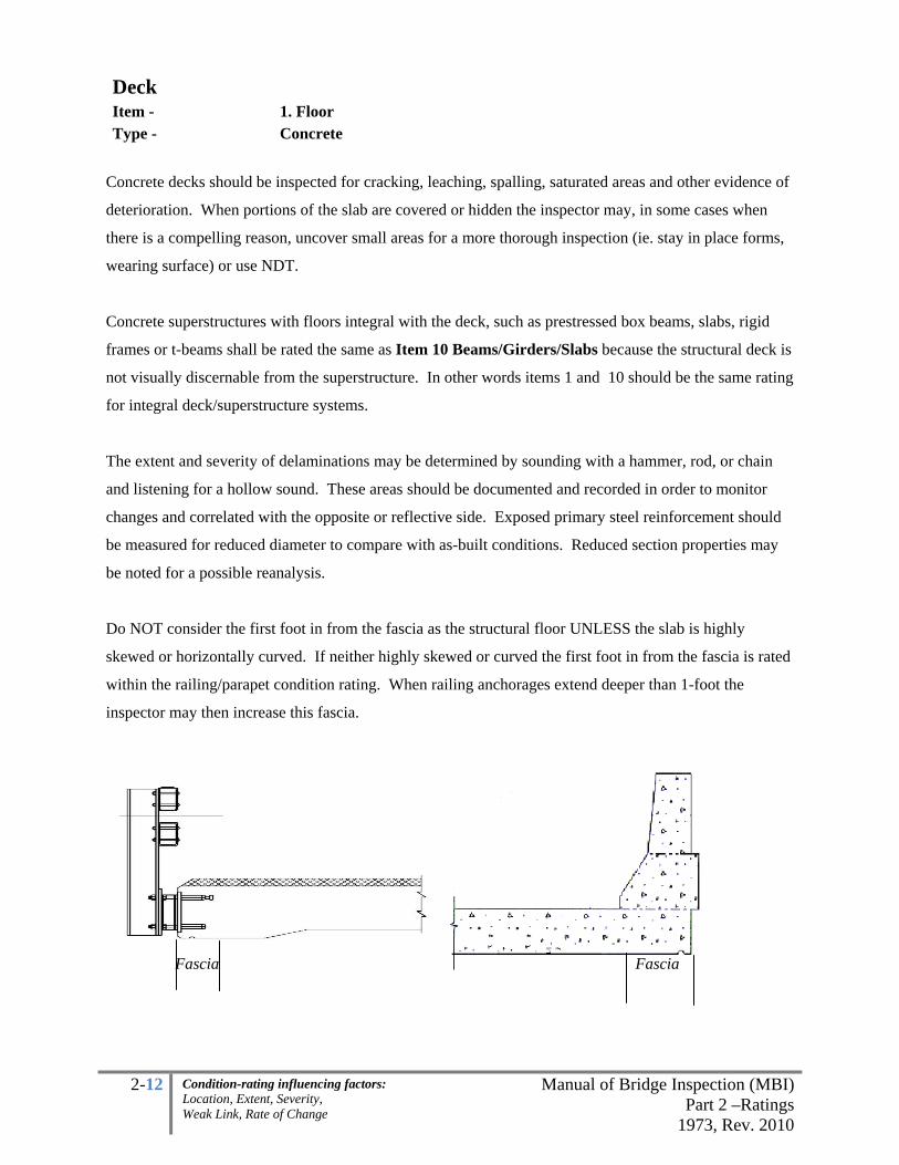
2-12 Manual of Bridge Inspection (MBI)Part 2 –Ratings
1973, Rev. 2010
Condition-rating influencing factors: Location, Extent, Severity, Weak Link, Rate of Change
Deck Item - 1. Floor Type - Concrete
Concrete decks should be inspected for cracking, leaching, spalling, saturated areas and other evidence of
deterioration. When portions of the slab are covered or hidden the inspector may, in some cases when
there is a compelling reason, uncover small areas for a more thorough inspection (ie. stay in place forms,
wearing surface) or use NDT.
Concrete superstructures with floors integral with the deck, such as prestressed box beams, slabs, rigid
frames or t-beams shall be rated the same as Item 10 Beams/Girders/Slabs because the structural deck is
not visually discernable from the superstructure. In other words items 1 and 10 should be the same rating
for integral deck/superstructure systems.
The extent and severity of delaminations may be determined by sounding with a hammer, rod, or chain
and listening for a hollow sound. These areas should be documented and recorded in order to monitor
changes and correlated with the opposite or reflective side. Exposed primary steel reinforcement should
be measured for reduced diameter to compare with as-built conditions. Reduced section properties may
be noted for a possible reanalysis.
Do NOT consider the first foot in from the fascia as the structural floor UNLESS the slab is highly
skewed or horizontally curved. If neither highly skewed or curved the first foot in from the fascia is rated
within the railing/parapet condition rating. When railing anchorages extend deeper than 1-foot the
inspector may then increase this fascia.
Fascia Fascia

2-13 Manual of Bridge Inspection (MBI)Part 2 –Ratings
1973, Rev. 2010
Condition-rating influencing factors: Location, Extent, Severity, Weak Link, Rate of Change
Deck Item - 1. Floor Type - Concrete
Rating Spalling with Exposed
Reinforcement (Delaminations)
Damp or Dark Areas
or Saturation Cracking
% of area not including the fascias
1
Excellent No signs of distress, no discoloration
Very Good Minor delaminations, minor spalling
Minor discoloration
Isolated hairline cracking with no rust staining, no dampness, no leakage
Good Up to 1% Up to 5%
Minor problems, hairline cracking with isolated leaking, efflorescence. No rust staining. Map cracking combined with mottled areas up to 5%
2
Satisfactory Up to 5% (unsound areas up to 10%) Up to 10%
Minor structural cracking with leaking, efflorescence and rust staining. Map cracking combined with mottled areas up to 10%
Fair
Up to 10%, (unsound areas up to 20%) slab with more than 1/3 primary bars exposed in one transverse plane
Up to 20%Structural cracking with leaking, efflorescence and rust staining. Map cracking combined with mottled areas up to 20%
3 Poor
Combined total not exceeding 30% with more than 4 adjacent exposed reinforcing bars having greater than 10% section loss to the original diameter.
Advanced cracking with heavy leaking, efflorescence and rust staining. Hairline map cracking combined with mottled areas up to 30%
Serious Up to 30% spalling, delamination with more than 5 adjacent reinforcing bars have greater than 25% section loss to the original diameter OR Up to 50% damp/dark areas
4
Critical
More than 30% spalling, delamination with more than 10 adjacent reinforcing bars having greater than 25% section loss to the original diameter OR More than 50% damp/dark areas; Evidence that full depth hole(s), leading to structural failure of the slab in the traveled lane.
Imminent Failure
Major deterioration in critical structural components or obvious vertical or horizontal movement affecting structure stability. Bridge is closed to traffic but correction action may put back in light service
Failure Bridge closed, collapsed
Precursor to through-holes on the following page
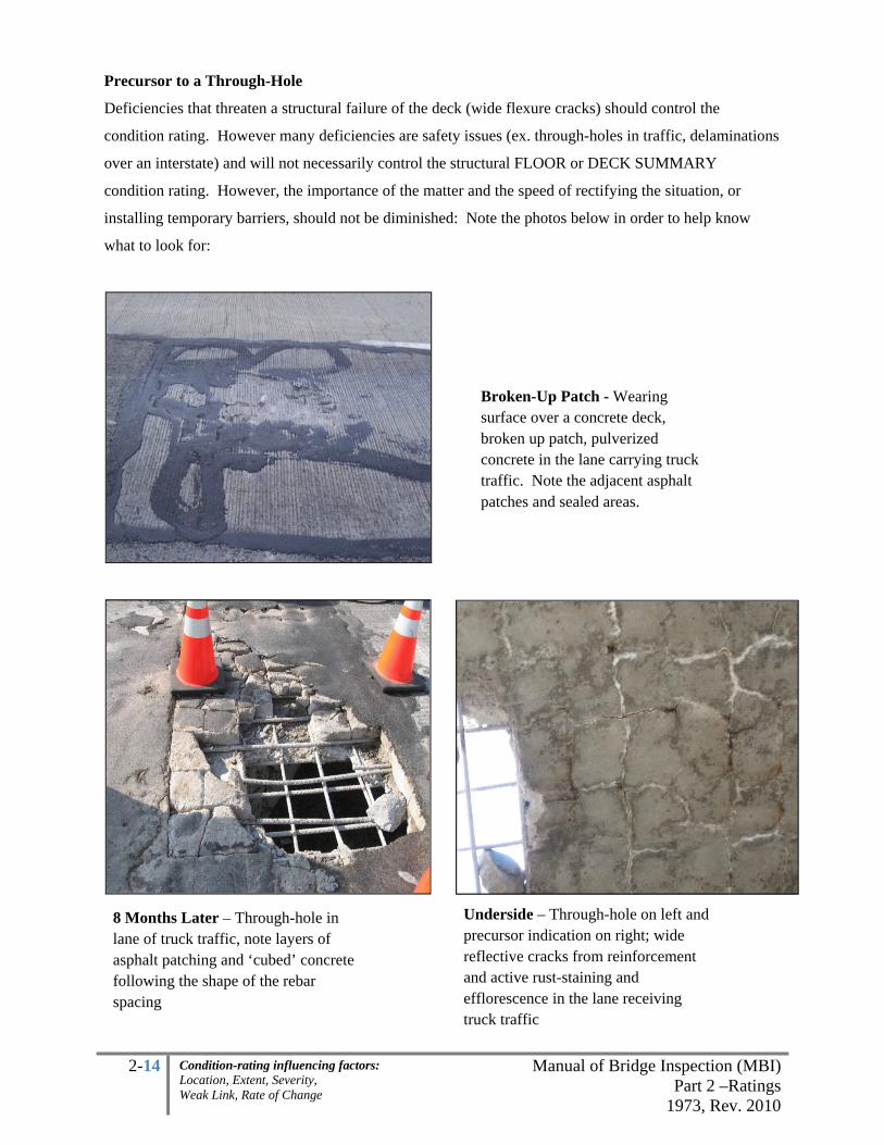
2-14 Manual of Bridge Inspection (MBI)Part 2 –Ratings
1973, Rev. 2010
Condition-rating influencing factors: Location, Extent, Severity, Weak Link, Rate of Change
Precursor to a Through-Hole
Deficiencies that threaten a structural failure of the deck (wide flexure cracks) should control the
condition rating. However many deficiencies are safety issues (ex. through-holes in traffic, delaminations
over an interstate) and will not necessarily control the structural FLOOR or DECK SUMMARY
condition rating. However, the importance of the matter and the speed of rectifying the situation, or
installing temporary barriers, should not be diminished: Note the photos below in order to help know
what to look for:
Broken-Up Patch - Wearing surface over a concrete deck, broken up patch, pulverized concrete in the lane carrying truck traffic. Note the adjacent asphalt patches and sealed areas.
8 Months Later – Through-hole in lane of truck traffic, note layers of asphalt patching and ‘cubed’ concrete following the shape of the rebar spacing
Underside – Through-hole on left and precursor indication on right; wide reflective cracks from reinforcement and active rust-staining and efflorescence in the lane receiving truck traffic

2-15 Manual of Bridge Inspection (MBI)Part 2 –Ratings
1973, Rev. 2010
Condition-rating influencing factors: Location, Extent, Severity, Weak Link, Rate of Change
Deck Item - 1. Floor Type - Timber
Timber decks should be examined for decay especially when bearing on the stringers, or between layers
of planking or laminate pieces. Note loose connections and differential bending.
Abrasion due to stones on the top surface will abrade into the timber floor in the wheel path. This is
where moisture tends to pond and promotes accelerated rot. Consider the first twelve inches on both
fascias sacrificial before it starts to control the condition rating. Where the timbers span the distance
between abutments the floor rating must be the same as the Superstructure: beam/girder/slab rating.
Noticeable deflection, under traffic, of the timber floor between stringers may be a strong indicator of
deficiency.
Rating Condition Description
1 Excellent No noticeable or noteworthy deficiencies which affect the condition of the deck.
Very Good No crushing, rotting, or splitting. Tightly secured to floor system. Very few
minor deficiencies.
Good Minor checking or splitting with a few loose planks.
2 Satisfactory
More than 30% of planks are checked or split but sound. Some loose planks.
Fire damage limited to surface scorching with no measurable section loss. Some
wet areas noted. A few planks (under 5%) are in need of replacement.
Fair
Numerous (30 - 40%) planks checked, split, rotted, or rushed. Majority of
planks are loose. Fire damage limited to surface charring with minor,
measurable section loss. Some planks (5 - 10%) are in need of replacement.
3 Poor
Majority (over 40%) of the planks are rotted, crushed, or split. Fire damage
with significant section loss which may reduce the load carrying capacity of the
member. Over 10% of the planks are in need of replacement.
Serious Severe signs of structural distress are visible. Major decay or fire damage is
present which has substantially reduced the load carrying capacity of the deck.
4 Critical Advanced deterioration with partial deck failure. May be necessary to close
bridge until corrective action is taken.
Im. Failure Bridge closed, corrective action will put it back in light service
Failed Bridge closed, replacement necessary

2-16 Manual of Bridge Inspection (MBI)Part 2 –Ratings
1973, Rev. 2010
Condition-rating influencing factors: Location, Extent, Severity, Weak Link, Rate of Change
Deck Item - 1. Floor Type - Steel Grid
Steel Grid decks should be examined for corrosion, section loss, broken tie-down welds, fatigue cracking
of bars or bar connection welds and any loose connections. These can be noticed visually or by hearing
the tertiary bars rattle against secondary bars under live load. Closed or filled grids are susceptible to the
build-up of rust on the grid elements embedded in the concrete, which can cause expansion of the deck
and break the tie-down welds, causing uplift or distorting the supporting structure. Measuring deck
panels and inspecting for uplift at set intervals can track this growth.
Loose connections are often easy to detect due to the load clanking sound under traffic. Be careful
inspecting open grids from below because debris and moisture sloughs off of traveling vehicles.
Rating Condition General Deficiencies
1 Excellent No noticeable or noteworthy deficiencies which affect the condition of the deck.
Very Good Tightly secured to floor system with no rust.
Good Loose at some connections with minor rusting. A few cracked welds and/or
broken grids but tightly secured.
2 Satisfactory Considerable corrosion with indications of initial section loss. Loose at many
locations. Some cracked welds and/or broken grids.
Fair Heavy corrosion with areas of section loss. Loose at numerous locations.
Several cracked welds and/or broken grids.
3 Poor
Heavy rusting resulting in considerable section loss and some small holes due
to missing bars through deck in the traveling lanes. Numerous welds cracked
and/or grids broken.
Serious Most welds cracked and/or grids broken. Severe or critical signs of structural
distress are visible.
4 Critical Unless closely monitored it may be necessary to close bridge, many holes
through deck.
Im. Failure Bridge closed. Correction action may put back in light service.
Failed Bridge closed. Replacement necessary.

2-17 Manual of Bridge Inspection (MBI)Part 2 –Ratings
1973, Rev. 2010
Condition-rating influencing factors: Location, Extent, Severity, Weak Link, Rate of Change
Deck Item - 1. Floor Type - Steel – Stay In Place Forms Filled with Asphalt (no concrete)
Asphalt Filled Stay-in-Place (SIP) forms should be examined for corrosion, section loss, and loose
connections. When filled with asphalt the SIP form functions as the structural deck. Where concrete
exists rate as the concrete floor item and do not consider the SIP in the condition rating.
Remove surface corrosion especially in critical areas. DO NOT Consider the first twelve inches on both
fascias in the condition rating. Weep holes are not considered section loss. Corrosion on galvanized pans
usually begins with the breakdown of the galvanizing which appears as white deposits, not to be confused
with salt or efflorescence deposits.
Look at the top for areas of distressed asphalt that would indicate deflection of the SIP forms. From the
underside inspect for locations where asphalt is visible through corrosion holes. Adjacent holes in
SIP ribs are more critical than isolated holes.
Rating Condition Corrosion of Steel
Section Loss
(leading to asphalt exposed on the
underside)
1 Excellent
Very Good None, minor breakdown of
galvanizing None
Good Minor surface rusting Minor
2 Satisfactory Considerable corrosion Initiating areas of section loss
Fair
Heavy corrosion at the beam or stringer connections on the splices
Some areas of section loss in traveling lanes. Areas with some small corrosion
holes (not drain holes)
3 Poor Many non adjacent areas in traveling lanes. Additional areas may have some small
corrosion holes Heavy corrosion between beams and stringers
Serious Some holes adjacent in traveled lane
4 Critical Many adjacent ribs with holes in the wheel line
Im. Failure Bridge closed, corrective action will put it back into light service
Failed Bridge closed, replacement necessary

2-18 Manual of Bridge Inspection (MBI)Part 2 –Ratings
1973, Rev. 2010
Condition-rating influencing factors: Location, Extent, Severity, Weak Link, Rate of Change
Deck Item - 2. Wearing Surface Type - Asphalt
The primary function of a wearing surface is to provide a smooth riding surface and to protect the
underlying floor. It should be examined for rideability, cracks, delaminations, patches and signs of
deterioration. Allow the traveled lanes to dictate percentages. Update the wearing surface thickness in
the inventory.
Rating Condition Distress Surface Area
(potholes, irregular patches) Cracking, Rutting
1 Excellent New, none, smooth riding surface none
Very Good Minor, smooth riding surface a few hairline cracks
Good Up to 1%, with minor potholes, still
providing smooth riding surface minor cracking, minor rutting
2 Satisfactory
up to 10%, still providing smooth
riding surface
transverse cracks and/or map
cracking
Fair up to 15%
transverse cracks and/or map
cracking through much of the
surface, moderate rutting
3 Poor
up to 25% and causing rough riding
surface
multiple transverse cracks and/or
map cracking throughout most of
the wearing surface, rutting
Serious up to 30% and very irregular surface
causing bridge vibration under live load
Large portions of the wearing
surface is cracking and broken up,
rutting up to 1”
4 Critical
more than 30% and causing bridge
vibration under live load
major cracking, rutting deeper than
1”
Im. Failure
Any worse than above
Failed

2-19 Manual of Bridge Inspection (MBI)Part 2 –Ratings
1973, Rev. 2010
Condition-rating influencing factors: Location, Extent, Severity, Weak Link, Rate of Change
Deck Item - 2. Wearing Surface Type - Concrete
Allow the traveled lane to dictate percentages. Update the wearing surface thickness in the inventory.
Rating Condition
Distress Surface Area
(delaminations, unsound
patches)
Asphalt
Patches
and
Potholes
and Spalls
Cracking
1 Excellent
no scaling, no delaminations,
smooth riding surface None none
Very Good Minor, smooth riding surface Minor a few hairline cracks
Good
Up to 2%, minor
delaminations, smooth riding
surface
Up to 1% several hairline cracks, may have
a few up to 1/16” wide
2 Satisfactory
Up to 10%, smooth riding
surface Up to 5%
transverse cracks and/or map
cracking may exist, up to 1/16”
wide
Fair Up to 15% transverse cracks and/or map
cracking spaced greater than 5’
3 Poor
Up to 25% and causing rough
riding surface Up to 10%
multiple transverse cracks and/or
map cracking greater than 1/16"
wide and spaced closer than 5’
Serious Up to 30%
4 Critical
more than 30% causing
bridge vibration under live
load
More than
10% major cracking
Im. Failure Any worse than above
Failed

2-20 Manual of Bridge Inspection (MBI)Part 2 –Ratings
1973, Rev. 2010
Condition-rating influencing factors: Location, Extent, Severity, Weak Link, Rate of Change
Deck Item - 3. Curbs, Sidewalks, Walkways
4. Median (when Median is only a curb or walkway) Type - All
The sidewalk allows for the safe passage of pedestrians. Look for impact damage, proper alignment,
broken or loose sections, exposed steel and weathering. Verify that vertical offsets do not exist and
proper support exists along the fascias. A vertical offset would be considered greater than 5/8”. Do not
consider approach curbs/sidewalks/walkways in this condition rating. Use the comments section to
describe the condition of the approach sidewalk/curb including locations of settlement of the approach
sidewalk/curb at the bridge. Curbs should be examined for proper alignment and anchorage.
Rating Condition General
1 Excellent New
Very Good Some minor problems noted
Good Scattered minor problems
2 Satisfactory
Structural elements show some minor deterioration. No vertical offsets more
than 5/8” exist.
Fair All primary structural elements are sound but have minor section loss,
deterioration or spalling. Vertical offset(s) may exist. Moderate cracking.
3 Poor
Advanced section loss, deterioration, spalling or scour. Vertical offset(s) exist.
Cracks in concrete less than 1” wide.
Serious
Loss of section, deterioration or spalling has seriously affected primary
structural components. Local failures are possible. Fatigue cracks in steel or
shear cracks in concrete may be present. Vertical offset(s) exist. Cracks in
concrete 1” wide.
4 Critical
Advanced deterioration of primary structural elements. Cracks in concrete are
wider than 1”. Fatigue cracks in steel or shear cracks in concrete may be
present. Structural support has been removed.
Im. Failure
Major deterioration or section loss present in critical structural components or
obvious vertical or horizontal movement affecting structure stability. Sidewalk
is closed but correction action may put back in light service
Failed Out of service - beyond corrective action

2-21 Manual of Bridge Inspection (MBI)Part 2 –Ratings
1973, Rev. 2010
Condition-rating influencing factors: Location, Extent, Severity, Weak Link, Rate of Change
Deck Item - 4. Median (when Median is a Parapet or Railing)
5. Railing Type - All Railings and parapets provide rigid support as to retain errant vehicles on the roadway and protect the
traveling public. Look for structural deficiencies, aesthetic deficiencies, loose connections, 'catch' points,
missing bolts/nuts and verify lateral stability of posts and railing. Inspect post and beam railing systems
for collision damage and loss of anchorage. “Loss of section” includes section loss to rebar within spalled
parapets. One-foot fascias should be considered within this rating where the railing is supported or
anchored into the fascia.
Rating Deficiencies
1 Excellent New
Very Good Minor
Good Some minor problems, minor impact damage
2 Satisfactory Structural elements show some minor deterioration, minor section loss, spalling
Fair
All primary structural elements are sound but have minor section loss, deterioration
or spalling. A few post anchors are exposed due to the fascia deterioration. Minor
impact damage.
3 Poor
Advanced section loss, deterioration or spalling (reinforcing bars have greater than
10% section loss to the original diameter for more than 4 adjacent exposed bars).
Anchors are exposed due to the fascia deterioration, not more than 2 consecutive
posts. Isolated loose or bent post.
Serious
Loss of section, deterioration or spalling (reinforcing bars have greater than 25%
section loss to the original diameter for more than 5 adjacent exposed bars has
seriously affected primary structural components. A few consecutive posts are loose
or bent. Up to 4 consecutive anchorages exposed on the deck fascia underside.
4 Critical
Advanced deterioration of primary structural elements (reinforcing bars have greater
than 25% section loss to the original diameter for more than 10 adjacent exposed
bars). Fatigue cracks in steel or shear cracks in concrete may be present. Unless
closely monitored it may be necessary to close lanes until corrective action is taken.
Several consecutive posts are loose or bent. Shifting, rotation, portion missing.
Im. Failure
Major deterioration or section loss present in critical structural components or
obvious vertical or horizontal movement affection structure stability. Lane(s) are
closed to traffic but correction action may put back into light service
Failed Out of service - beyond corrective action

2-22 Manual of Bridge Inspection (MBI)Part 2 –Ratings
1973, Rev. 2010
Condition-rating influencing factors: Location, Extent, Severity, Weak Link, Rate of Change
Deck Item - 6. Drainage Type - All Proper drainage systems allow the runoff to evacuate the bridge deck safely and efficiently. These
systems include but are not limited to: gratings, scuppers, drains, downspouts, troughs and/or outfalls.
Effective drainage is essential for the proper maintenance of a bridge. Examine the drainage system for
clogging, ponding, vegetation and adequacy. All structures with deck items require a rating for drainage.
Drainage may be the root cause for most of the deficiencies found on bridges; however this rating is
primarily concerned with how runoff is evacuating the wearing surface and secondarily concerned with
how the system is functioning below the deck. It is very helpful to perform the drainage inspections
during or shortly after a rainfall event; however this is not always practical.
Rating Condition General Clogging Ponding
1 Excellent New, No problems noted Very Good All of runoff is getting off of the deck, minor scattered problems
Good All of runoff is getting off of the deck with minor deficiencies to drainage system.
2 Satisfactory
Most of the water getting off of deck with minor deficiencies to drainage system.
Few scuppers continually clog. Minor ponding along the curb line.
Fair
All primary structural elements are sound but have minor section loss, deterioration or spalling.
Up to a quarter of scuppers/grates continually clog.
Minor ponding may exist in the shoulder or outside of the traveling lanes.
3
Poor Advanced section loss or deterioration affecting the structure.
Up to half of the scuppers/grating continually clog.
Ponding is beginning to cross into the traveling lane.
Serious
Loss of section or deterioration has seriously affected primary structural components. Local failures of the drainage system.
More than half of the scuppers/grating continually clog.
Significant ponding into the traveling lane with potential for hydroplaning or icing.
4 Critical
Unless closely monitored it may be necessary to close the lane(s) until corrective action is taken. Local flooding, hydroplaning or icing due to improper drainage system.
Im. Failure Major deterioration, lane closures exist due to drainage but corrective action may put back in light service
Failed Out of service - beyond corrective action

2-23 Manual of Bridge Inspection (MBI)Part 2 –Ratings
1973, Rev. 2010
Condition-rating influencing factors: Location, Extent, Severity, Weak Link, Rate of Change
Deck Item - 7. Expansion Joints Type - All Expansion joints provide the following functions:
1. Structural: accommodate expansion and contraction of the bridge deck and
superstructure, and rotation of the beam ends
2. Safety: transfer traffic loads across the opening and
3. Prevention: control runoff moisture and debris.
Examine carefully for signs of leakage, proper opening, anchorage, and deterioration. Deterioration of the
backwall however will be included with the backwall item. Consider bringing down the expansion joint
rating when the joint-anchorages are affected (ex. deep spalls in the header exposing the cheese plates).
Condition of deflection joint seals or construction joints (typically 1” or less) should not be given a
condition rating but may be noted in the comments section.
Many joint designs do allow for leakage (ie. open joints, sliding plates etc.). Do not consider this a
deficiency for such joints. Note: Deficiencies for sidewalk and curb plates may be added to the
comments but their condition shall not govern the expansion joint condition rating.
Expansion joints are effective locations to track changes in the bridge at different temperatures. These
distances may be compared to the bearing movements to verify proper function. Consider recording all
expansion joints’ temperature, longitudinal distance and the exact location where the measurement was
taken in the comments to compare movements in previous years and to track in future inspections. Units
up to 1/8” increments are acceptable. Measurements taken in this case should record the vertical,
horizontal or longitudinal (taken parallel with traffic not with the skew) dimensions. Abnormalities will
include anything outside of the design limits. The movable bearing inspection form in the appendix may
be used as a guide when recording and monitoring bridge movements. Rate the joints even if they are
covered with asphalt.
For structures with a ¾” or 1” poured joint or construction joint (ex. semi-integral abutment type
structures) do not rate these under the 7 Expansion Joints item. If deficiencies do exist on the
construction joint then record them within the comments section.

2-24 Manual of Bridge Inspection (MBI)Part 2 –Ratings
1973, Rev. 2010
Condition-rating influencing factors: Location, Extent, Severity, Weak Link, Rate of Change
Deck Item - 7. Expansion Joints Type - Any
Condition
Rating Runoff
Expansion and Contraction
Opening
Armor and
Anchorage
1
Excellent No leakage
Very
Good
Minor isolated leakage the
joint, debris may be present
Measurements exhibit normal
expansion and contraction
Minor surface
delaminations in
header
Good
Localized signs of leakage
along the joint may be
present, debris
Measurements exhibit normal
expansion and contraction
A few delaminations
or spalls or cracking in
the header
2
Satisfactor
y
Leakage in several places.
Gland is partially separated
from the armor or has
minor tears. Significant
debris
Minor abnormalities in the
longitudinal measurements may
exist
Spalls or cracking in
the deck and/or header
may be present
adjacent to the joint.
Gouges in armor.
Fair
Excessive leakage along the
joint in many locations.
Gland may be partially
pulled out of the extrusion.
paved over
Abnormalities in measurements.
Bent or misaligned fingers may be
observed. Minor vertical offset;
note this is more important where
plow catch points exist
'Clanking' under heavy
truck traffic only with
small spalls or
cracking. Gouges in
armor
3Poor
Gland has been pulled
completely out of the
extrusion.
Significant abnormalities in the
measurements. Missing or broken
fingers. Up to 1” vertical
misalignment (plow catch point)
Clanking in one lane
under truck traffic.
Major spalls or
significant cracking.
Serious
Major abnormalities in the
measurements, up to 2”
misalignment (plow catch points)
Visible movement and
clanking under all
traffic loads in one
lane, major spalls .
4 Critical
Major abnormalities in the longitudinal, vertical and/or horizontal measurements, greater
than 2” misalignment (plow catch points exist). Tight on one side and open in the other.
Visible movement and clanking under all traffic loads in all lanes, major spalls. Anchorage
separation on multiple beams.

2-25 Manual of Bridge Inspection (MBI)Part 2 –Ratings
1973, Rev. 2010
Condition-rating influencing factors: Location, Extent, Severity, Weak Link, Rate of Change
Deck Item - 8. SUMMARY Type - All
DECK
1. Floor 2. Wearing Surface 3. Curbs, Sidewalks & Walkways 4. Median 5. Railing 6. Drainage 7. Expansion Joints 8. SUMMARY
Note: 1-4 Individual Items % are based on the WORST SPAN while the 9-0 Summary Items % are based
on the item throughout the TOTAL BRIDGE. Therefore the 9-0 rating will, in some cases where 1 span
is considerably worse than the entire bridge, be higher than the conversion below. This should be the
exception rather than the rule.
Deficiencies that threaten a structural failure of the deck should control the condition rating. Many
deficiencies are safety issues (ex. delaminations over an interstate) that will not necessarily control the
structural deck summary condition rating. However, the importance of the matter and the speed of
rectifying the situation, or installing temporary barriers, should not be diminished:
1-4 INDIVIDUAL (Worse Span) 9-0 DECK SUMMARY (Total Deck)
1 9-Excellent
8-Very Good
7-Good
2 6-Satisfactory
5-Fair
3 4-Poor
3-Serious
4 2-Critical
1-Im. Failure
0-Failed


2-26 Manual of Bridge Inspection (MBI)Part 2 –Ratings
1973, Rev. 2010
Condition-rating influencing factors: Location, Extent, Severity, Weak Link, Rate of Change
SUPERSTRUCTURE The superstructure is the entire portion of a bridge below the structural floor and above the abutment seats
and pier seats. The superstructure transmits the deck loads to the substructure. Steel structures with lower
lateral bracing, pins and hangers, transverse floor beams and stringers, or any unusual connection details
will be carefully inspected for cracks, design details, or fabricating details. While bearing devices and
bracing may cause serious problems, rarely will the condition rating of the superstructure be reduced
because of secondary members. Bearing for trusses and twin girder bridges and bracing on highly
skewed bridges may be given full consideration in the superstructure rating.
Note: 1-4 Individual Items %are based on the WORST SPAN while the 9-0 Summary Items % are based
on the item throughout the TOTAL BRIDGE (EXCEPT WEAK LINK COMPONENTS which can
control the entire bridge). Therefore the 9-0 rating will, in some cases where 1 span is considerably worse
than the entire bridge, be higher than the conversion.
Generally, in coding the items, start at the top, “Excellent”, and read down the condition ratings until you
have moved down to a rating that is worse than the actual condition item being coded. Choose the rating
above the rating that describes a worse condition. The vertical lines bordering the columns shall be
treated as “or” conditions ie. choose the lowest or worst column. Always rate what you see AND allow
indications of deficiencies to influence a lower condition rating when the unseen item is directly
affected.
SUPERSTRUCTURE
9. Alignment 10. Beams/Girders/Slab
11. Diaphragms or Cross frames 12. Joists/Stringers
13. Floorbeams 14. Floorbeam Connections
15. Verticals 16. Diagonals
17. End posts 18. Upper Chord
19. Lower Chord 20. Gusset Plate
21. Lateral Bracing 22. Sway Bracing 23. Portals 24. Bearing Devices
25. Arch 26. Arch Columns or Hangers
27. Spandrel Walls 28. Protective Coating System (PCS)
29. Pins/Hangers/Hinges 30. Fatigue Prone Details (E, E’)
31. Live Load Response (E or S) 32. SUMMARY
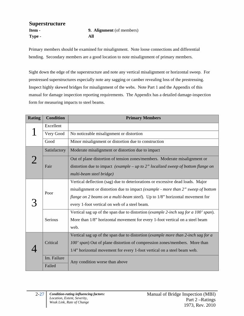
2-27 Manual of Bridge Inspection (MBI)Part 2 –Ratings
1973, Rev. 2010
Condition-rating influencing factors: Location, Extent, Severity, Weak Link, Rate of Change
Superstructure Item - 9. Alignment (of members) Type - All
Primary members should be examined for misalignment. Note loose connections and differential
bending. Secondary members are a good location to note misalignment of primary members.
Sight down the edge of the superstructure and note any vertical misalignment or horizontal sweep. For
prestressed superstructures especially note any sagging or camber revealing loss of the prestressing.
Inspect highly skewed bridges for misalignment of the webs. Note Part 1 and the Appendix of this
manual for damage inspection reporting requirements. The Appendix has a detailed damage-inspection
form for measuring impacts to steel beams.
Rating Condition Primary Members
1 Excellent
Very Good No noticeable misalignment or distortion
Good Minor misalignment or distortion due to construction
2 Satisfactory Moderate misalignment or distortion due to impact
Fair
Out of plane distortion of tension zones/members. Moderate misalignment or
distortion due to impact (example – up to 2” localized sweep of bottom flange on
multi-beam steel bridge)
3 Poor
Vertical deflection (sag) due to deteriorations or excessive dead loads. Major
misalignment or distortion due to impact (example - more than 2” sweep of bottom
flange on 2 beams on a multi-beam steel). Up to 1/8” horizontal movement for
every 1-foot vertical on web of a steel beam.
Serious
Vertical sag up of the span due to distortion (example 2-inch sag for a 100’ span).
More than 1/8” horizontal movement for every 1-foot vertical on a steel beam
web.
4 Critical
Vertical sag up of the span due to distortion (example more than 2-inch sag for a
100’ span) Out of plane distortion of compression zones/members. More than
1/4” horizontal movement for every 1-foot vertical on a steel beam web.
Im. Failure Any condition worse than above
Failed

2-28 Manual of Bridge Inspection (MBI)Part 2 –Ratings
1973, Rev. 2010
Condition-rating influencing factors: Location, Extent, Severity, Weak Link, Rate of Change
Superstructure Item - 10. Beams/Girders/Slab Type - All
Section loss and cracking are the two main deficiencies to inspect for in beams/girders/slabs. Concrete
superstructure floors integral with the deck, such as prestressed box beams, slabs or rigid frames, shall be
rated the same as the Beams/Girders/Slabs item where the deck is not visually discernable from the
superstructure. For horizontally curved and non-redundant structures the fascia beams shall control the
condition rating.
Cracking:
Cracking may dictate the condition rating for steel beams. Any crack in a fracture critical member would
have a major impact in a primary member. A minor crack (less than 2” long or dormant) in the tension
area of a primary redundant member may not require immediate action depending on location.
For cracks in E & E' Fatigue Prone Details also code Item No. 30 Fatigue Prone Details. The presence of
new or propagated cracks in a fracture critical member warrants an immediate verbal report to the bridge
owner/program manager. Take measurements (make notes in the comments and paint comments on the
bridge) each year to track growth.
Section loss:
Surface corrosion will be included in the Protective Coating System (PCS) rating only. Measure and
document section loss in order to update the load rating and discuss changes with the Load Rating
engineer. Inspectors are expected to clean areas with scrapers, hammers and wire brush and it is
strongly recommended to use UT Gauges, calipers or pit gauges for quantitative results.
Buckling can initiate in the compression zones of the flange or in the webs and is exhibited due to section
loss, unbraced conditions or impact. The web directly above the bearing (bearing area is generally 18
times the thickness long x 8-inches high) is significant when more than 50% loss is measured in the web
reducing the reserve capacity.

2-29 Manual of Bridge Inspection (MBI)Part 2 –Ratings
1973, Rev. 2010
Condition-rating influencing factors: Location, Extent, Severity, Weak Link, Rate of Change
Superstructure Item - 10. Beams/Girders/Slab Type – Steel
Condition *Section Loss and Deterioration **Cracks
1 Excellent None Very Good No measurable section loss or very minor section loss
Good Insignificant section loss, minor Minor problems; repaired, arrested or retrofitted cracks
2
Satisfactory
Minor section loss (ex. corr. hole in redundant fascia web or any interior beam stiffener or behind a bearing, Minor pitting, isolated areas of loss throughout member,) some areas of deterioration
Some minor deterioration; Broken welds possible but no cracks in the base metal
Fair
Beams are sound with some deterioration, moderate section loss (ex. Some areas of heavy pitting under expansion joints, corrosion hole allowed only in fascia beams in redundant structure, less than 1/3 loss in flanges in max-bending regions)
Minor cracking (ie. small, all less than 2” long, stable cracks in base metal in compression zone, cracks in weld metal)
3
Poor
Advanced section loss (ex. 1 non redundant or interior member with more than 1/3 loss in flange at flexure zone or more than 50% loss in web at supports, corrosion hole in interior or non redundant beam)
Fatigue or out-of-plane bending cracks (ie. cracks, any longer than 2” in compression zone, or small crack(s) in tension zone). Note: any crack in the base metal of a FCM parallel to the primary stress shall be “Poor” or less.
Serious
Section loss is seriously affecting beams, local failures are possible (ex. Extensive perforations or loss through beams, perforations through many beams)
Fatigue or out-of-plane bending cracks (ie. several cracks, any longer than 2” in compression zone, or several small crack(s) in tension zone). Multiple out of plane or fatigue cracks in one beam. Note: any crack in the base metal of a FCM perpendicular to the primary stress shall be “Serious” or less.
4 Critical
Advanced deterioration (ex. One beam is crushing) lane should be closed or closely monitored. Distortion in a load path of a redundant member
Advanced deterioration, cracks have removed support or load path in base metal (ex. many working crack(s) in more than one location or longer than 2”, on the same beam and in tension zones)
Imminent Failure
Major section loss, deterioration or cracking that is worse than above (ex. Beams are crushing) and closed to traffic. Distortion in a load path of a non redundant member
Failed Beyond corrective action * Section loss is highly dependent on location, extent and severity; see the table for spot
measurements on the following page.**Minor versus advanced cracking depends on the
probability of propagation, location & length and may be given to the judgment of the Team

2-30 Manual of Bridge Inspection (MBI)Part 2 –Ratings
1973, Rev. 2010
Condition-rating influencing factors: Location, Extent, Severity, Weak Link, Rate of Change
Leader taking into consideration brittle fracture. For dormant cracks, consideration shall be given
in increasing the condition rating.
% Section Loss plate thicknesses
Depth of Section Loss
Original Plate Thickness (in) 1/4 1/2 5/8 3/4
1/16 25% 13% 10% 8% 1/8 50% 25% 20% 17%
3/16 75% 38% 30% 25% 1/4 100% 50% 40% 33%
5/16 corrosion hole
63% 50% 42% 3/8 75% 60% 50%
7/16 88% 70% 58% 1/2 100% 80% 67%
9/16 corrosion hole
90% 75% 5/8 100% 83%
11/16 corrosion hole
92% 3/4 100%
Section Loss (SL) – For localized point measurements, the above table gives percentages for
thickness reductions due to section loss (or loss of section). Location, extent and severity will
govern the condition rating. In general for shear if the area above the bearing 8” high and 18*t
long (where t is the thickness of the web) has more than 50% section loss then it is “advanced”
section loss and should be coded down to a “Poor” only if the loss is on an interior or
nonredundant beam. For moment more than 1/3 loss to the flange(s) in the maximum bending
zone or high moment region is also “advanced” and should be coded down to a “Poor” if the loss
is on an interior or nonredundant beam.
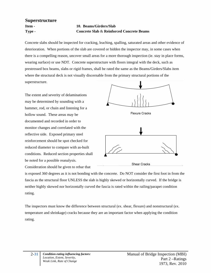
2-31 Manual of Bridge Inspection (MBI)Part 2 –Ratings
1973, Rev. 2010
Condition-rating influencing factors: Location, Extent, Severity, Weak Link, Rate of Change
Superstructure Item - 10. Beams/Girders/Slab Type - Concrete Slab & Reinforced Concrete Beams
Concrete slabs should be inspected for cracking, leaching, spalling, saturated areas and other evidence of
deterioration. When portions of the slab are covered or hidden the inspector may, in some cases when
there is a compelling reason, uncover small areas for a more thorough inspection (ie. stay in place forms,
wearing surface) or use NDT. Concrete superstructure with floors integral with the deck, such as
prestressed box beams, slabs or rigid frames, shall be rated the same as the Beams/Girders/Slabs item
where the structural deck is not visually discernable from the primary structural portions of the
superstructure.
The extent and severity of delaminations
may be determined by sounding with a
hammer, rod, or chain and listening for a
hollow sound. These areas may be
documented and recorded in order to
monitor changes and correlated with the
reflective side. Exposed primary steel
reinforcement should be spot checked for
reduced diameter to compare with as-built
conditions. Reduced section properties shall
be noted for a possible reanalysis.
Consideration should be given to rebar that
is exposed 360 degrees as it is not bonding with the concrete. Do NOT consider the first foot in from the
fascia as the structural floor UNLESS the slab is highly skewed or horizontally curved. If the bridge is
neither highly skewed nor horizontally curved the fascia is rated within the railing/parapet condition
rating.
The inspectors must know the difference between structural (ex. shear, flexure) and nonstructural (ex.
temperature and shrinkage) cracks because they are an important factor when applying the condition
rating.

2-32 Manual of Bridge Inspection (MBI)Part 2 –Ratings
1973, Rev. 2010
Condition-rating influencing factors: Location, Extent, Severity, Weak Link, Rate of Change
Superstructure Item - 10. Beams/Girders/Slab Type –
Concrete Slab & Reinforced Concrete Beams
Rating Spalling with Exposed
Reinforcement, Unsound Areas
Damp or Dark Areas (Saturation) Cracking
% of area not including the SLAB fascias
1
Excellent No signs of distress, no discoloration
Very Good Minor delaminations, minor spalling
Minor discoloration
Isolated hairline cracking with no rust staining, no dampness, no leakage
Good Up to 1% Up to 5%
Minor problems, hairline cracking with isolated leaking, efflorescence. No rust staining. Map cracking combined with mottled areas up to 5%
2
Satisfactory Up to 5% (unsound areas up to 10%)
Up to 10%Minor structural cracking with leaking, efflorescence and rust staining. Map cracking combined with mottled areas up to 10%
Fair
Up to 10%, (unsound areas up to 20%) slab with more than 1/3 primary bars exposed in one transverse plane
Up to 20%Structural cracking with leaking, efflorescence and rust staining. Map cracking combined with mottled areas up to 20%
3 Poor
Combined total not exceeding 30% with more than 4 adjacent exposed reinforcing bars having greater than 10% section loss to the original diameter.
Advanced cracking with heavy leaking, efflorescence and rust staining. Hairline map cracking combined with mottled areas up to 30%
Serious Up to 30% spalling, delamination with more than 5 adjacent reinforcing bars have greater than 25% section loss to the original diameter OR Up to 50% damp/dark areas
4 Critical
More than 30% spalling, delamination with more than 10 adjacent reinforcing bars having greater than 25% section loss to the original diameter OR More than 50% damp/dark areas; Evidence that full depth hole(s), leading to structural failure of the slab in the traveled lane.
Imminent Failure
Major deterioration in critical structural components or obvious vertical or horizontal movement affecting structure stability. Bridge is closed to traffic but correction action may put back in light service
Failure Bridge closed, collapsed

2-33 Manual of Bridge Inspection (MBI)Part 2 –Ratings
1973, Rev. 2010
Condition-rating influencing factors: Location, Extent, Severity, Weak Link, Rate of Change
Superstructure Item - 10. Beams/Girders/Slab Type - Prestressed Concrete – I-Beams, Composite and Non Comp Boxes Rating Condition % General Deficiencies Shear Keys Strands Exposed
1 Excellent No notable deficiencies
Very Good Minor deficiencies joints leaking in isolated areas
1 or 2 strands on one interior beam or less than 1% of total strands
Good Up to 1%, spalling along edge
joints leaking less than 10% of span length
Up to 10% with neighboring beam in similar condition or better.
2 Satisfactory Up to 5%, efflorescence,
spalling
Some joints leaking less than 25% of span length
Up to 15% with neighboring beam in good condition or in similar condition
Fair
Up to 10%, saturated fascia beams with 1 adjacent saturated interior beam
All joint keys leaking less than 50% of span
Up to 25% with neighboring beam in satisfactory condition or in similar condition
3 Poor
Up to 30%, saturated fascia and some interior beams. Spalls. Advanced Deterioration at beam ends. May have wide structural cracks
All joint keys leaking greater than 50% of span
Up to 40% with neighboring beam in fair condition or in similar condition
Serious Working structural cracks in one beam carrying traffic
Holes in web of beam carrying traffic
Up to 50% with neighboring beam in poor condition or in similar condition
4 Critical
More than 30%, wide structural cracks in two or more beams carrying traffic
More than 50% with neighboring beam in serious condition or in similar condition
Imminent Failure Noticeable sag Failed Any condition worse than above
Allow the worst beam carrying direct traffic to control, i.e. the fascia beam should not govern the rating
when located outside the traveled lanes
General Deficiencies – includes imperfection in the concrete (i.e. spalls, cracking, mottled area,
efflorescence, honeycombing, water in beams, missing cap on transverse tie rod, damaged concrete
around railing connection) and general beam alignment (i.e. loss of upward camber, twists, misalignment)
Shear keys (adjacent prestressed box beams only) –staining or wetted areas from runoff infiltration.
Exposed stands - include those strands visible and those strands not visible located :
1) Above a longitudinal cracks located in the bottom flange
2) Above a delamination
3) Above a spall with unsound or mottled concrete.
4) Consideration should also be given to those strands neighboring and above a corroded stirrup,
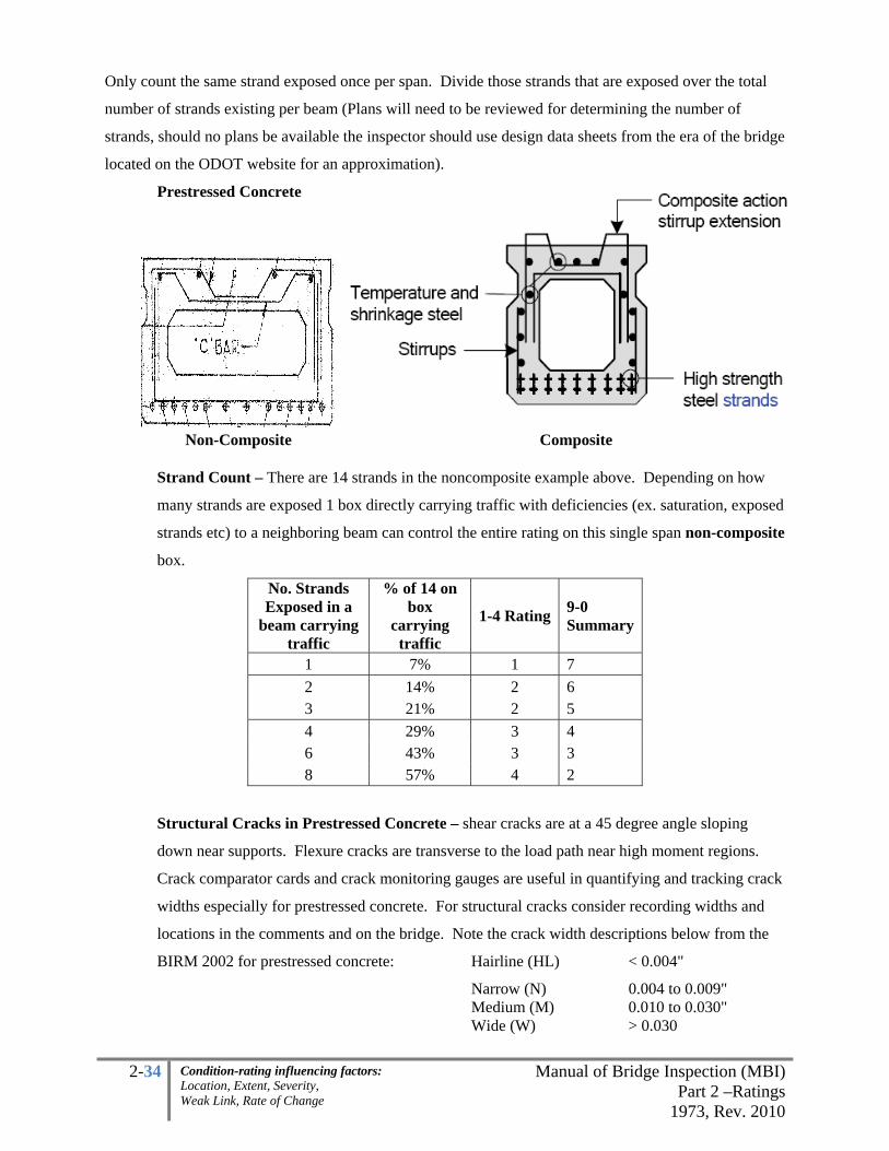
2-34 Manual of Bridge Inspection (MBI)Part 2 –Ratings
1973, Rev. 2010
Condition-rating influencing factors: Location, Extent, Severity, Weak Link, Rate of Change
Only count the same strand exposed once per span. Divide those strands that are exposed over the total
number of strands existing per beam (Plans will need to be reviewed for determining the number of
strands, should no plans be available the inspector should use design data sheets from the era of the bridge
located on the ODOT website for an approximation).
Prestressed Concrete
Non-Composite Composite
Strand Count – There are 14 strands in the noncomposite example above. Depending on how
many strands are exposed 1 box directly carrying traffic with deficiencies (ex. saturation, exposed
strands etc) to a neighboring beam can control the entire rating on this single span non-composite
box.
No. Strands Exposed in a
beam carrying traffic
% of 14 on box
carrying traffic
1-4 Rating 9-0 Summary
1 7% 1 7 2 14% 2 6 3 21% 2 5 4 29% 3 4 6 43% 3 3 8 57% 4 2
Structural Cracks in Prestressed Concrete – shear cracks are at a 45 degree angle sloping
down near supports. Flexure cracks are transverse to the load path near high moment regions.
Crack comparator cards and crack monitoring gauges are useful in quantifying and tracking crack
widths especially for prestressed concrete. For structural cracks consider recording widths and
locations in the comments and on the bridge. Note the crack width descriptions below from the
BIRM 2002 for prestressed concrete: Hairline (HL) < 0.004"
Narrow (N) 0.004 to 0.009" Medium (M) 0.010 to 0.030" Wide (W) > 0.030

2-35 Manual of Bridge Inspection (MBI)Part 2 –Ratings
1973, Rev. 2010
Condition-rating influencing factors: Location, Extent, Severity, Weak Link, Rate of Change
Superstructure Item - 10. Beams/Girders/Slab Type - Timber
Timber beams should be examined for decay especially where members are joined, or between layers of
planking or laminate pieces. Note loose connections and differential bending.
Sounding with a hammer or rod will help in determining hollow areas.
Rating Condition Timber Beams
1 Excellent
No noticeable or noteworthy deficiencies which affect the condition of the
superstructure.
Very Good Very good condition. No deterioration.
Good Timber is dry but has minor checking
2 Satisfactory
Timber shows minor deterioration. Less than 2% moist timber with moderate
checking.
Fair Timber is sound, may have minor section loss cracking. Less than 5% moist or
2% decayed timber with moderate checking.
3 Poor Advanced deterioration.
Serious Severe decay, cracking, splitting, or crushing of beams or stringers.
4 Critical
Advanced deterioration of timber. Unless closely monitored it may be necessary
to close the bridge until corrective action is taken. Structural capacity
inadequate.
Imminent Failure
Bridge closed. Corrective action may put back in light service.
Failed Bridge closed. Replacement necessary.
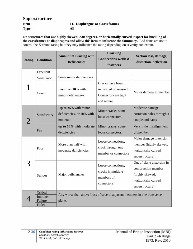
2-36 Manual of Bridge Inspection (MBI)Part 2 –Ratings
1973, Rev. 2010
Condition-rating influencing factors: Location, Extent, Severity, Weak Link, Rate of Change
Superstructure Item - 11. Diaphragms or Cross frames Type - All On structures that are highly skewed, >30 degrees, or horizontally curved inspect for buckling of the crossframes or diaphragms and allow this item to influence the Summary. End dams are not to control the X-frame rating but they may influence the rating depending on severity and extent.
Rating Condition Amount of Bracing with
Deficiencies
Cracking
Connections-welds &
fasteners
Section loss, damage,
distortion, deflection
1
Excellent
Very Good Some minor deficiencies
Good Less than 10% with
minor deficiencies
Cracks have been
retrofitted or arrested.
Connectors are tight
and secure.
Minor damage to member
2 Satisfactory
Up to 25% with minor
deficiencies, or 10% with
moderate
Minor cracks, some
loose connectors.
Moderate damage,
corrosion holes through a
couple end dams
Fair up to 50% with moderate
deficiencies
Minor cracks, some
loose connectors.
Very little misalignment
of member
3
Poor More than half with
moderate deficiencies
Loose connections,
crack through one
member or connectors
Major damage to tension
member (highly skewed,
horizontally curved
superstructure)
Serious Major deficiencies
Loose connections,
cracks in multiple
members of
connectors
Out of plane distortion in
compression member
(highly skewed,
horizontally curved
superstructure)
4 Critical Any worse than above Loss of several adjacent members in one transverse
plane. Imminent Failure Failed

2-37 Manual of Bridge Inspection (MBI)Part 2 –Ratings
1973, Rev. 2010
Condition-rating influencing factors: Location, Extent, Severity, Weak Link, Rate of Change
Superstructure Item - 12. Joists/Stringers
13. Floorbeams, 14. Floorbeam Connections Type - Steel
Floorbeams are transverse to traffic and joist/stringers are longitudinal with traffic. Connections include
the device that allows the load transfer through the floor system (ie. riveted clip angles, welds, stringer
seats, saddles etc.). Inspect coped areas for fatigue cracks.
The inspector should visually inspect all fracture critical (FC) structural members of the bridge within an
"arm's-reach" distance.
Floorbeams are deemed fracture critical where one or more of the following conditions exist:
• Hinged connection to support girders
• Spacing greater than 14’-0”
• No Stringers
• Stringers are configured as simple
beams
Arrow indicates the clip angle and
mechanical fasteners. This area is
considered the “connection”.
Connection may also be supplied by a
weld, saddle etc.

2-38 Manual of Bridge Inspection (MBI)Part 2 –Ratings
1973, Rev. 2010
Condition-rating influencing factors: Location, Extent, Severity, Weak Link, Rate of Change
Superstructure Item - 12. Joists/Stringers 13. Floorbeams 14. Floorbeam Connections Type - Steel
Condition *Section Loss and Deterioration **Cracks
1Excellent None Very Good No measurable section loss or very minor
Good Insignificant section loss, minor Minor problems; repaired, arrested or retrofitted cracks
2
Satisfactory
Minor section loss (ex. corr. hole in stiffener of any redundant beam or behind a bearing, Minor pitting, isolated areas of loss throughout member,) some areas of deterioration
Some minor deterioration; Broken welds possible but no cracks in the base metal
Fair
Beams are sound with some deterioration, moderate section loss (ex. Some areas of heavy pitting under expansion joints, corrosion hole allowed only in fascia beams in redundant structure, less than 1/3 loss in flanges in max-bending regions)
Minor cracking (ie. small, all less than 2” long, stable cracks in base metal in compression zone, cracks in weld metal)
3
Poor
Advanced section loss (ex. 1 non redundant or interior member with more than 1/3 loss in flange at flexure zone or more than 50% loss in web at supports, corrosion hole in interior or non redundant beam)
Fatigue or out-of-plane bending cracks (ie. cracks, any longer than 2” in compression zone, or small crack(s) in tension zone). Note: any crack in the base metal of a FCM parallel to the primary stress shall be “Poor” or less.
Serious
Section loss is seriously affecting beams, local failures are possible (ex. Extensive perforations or loss through beams, perforations through many beams)
Fatigue or out-of-plane bending cracks (ie. several cracks, any longer than 2” in compression zone, or several small crack(s) in tension zone). Multiple out of plane or fatigue cracks in one beam. Note: any crack in the base metal of a FCM perpendicular to the primary stress shall be “Serious” or less.
4Critical
Advanced deterioration (ex. One beam is crushing) lane should be closed or closely monitored. Distortion in a load path of a redundant member
Advanced deterioration, cracks have removed support or load path in base metal (ex. many working crack(s) in more than one location or longer than 2”, on the same beam and in tension zones)
Imminent Failure
Major section loss, deterioration or cracking that is worse than above (ex. Beams are crushing) and closed to traffic. Distortion in a load path of a non redundant member
Failed Beyond corrective action *Note: Section loss is highly dependent on location, extent and severity, for spot measurements refer to the table on the following page.

2-39 Manual of Bridge Inspection (MBI)Part 2 –Ratings
1973, Rev. 2010
Condition-rating influencing factors: Location, Extent, Severity, Weak Link, Rate of Change
**Note: Minor VS. advanced cracking depends on probability of propagation, location & length and may be given to the judgment of the Team Leader taking into consideration brittle fracture. For dormant cracks consideration should be made in increasing the rating.
% Section Loss plate thicknesses
Depth of Section Loss
Original Plate Thickness (in) 1/4 1/2 5/8 3/4
1/16 25% 13% 10% 8% 1/8 50% 25% 20% 17%
3/16 75% 38% 30% 25% 1/4 100% 50% 40% 33%
5/16 corrosion hole
63% 50% 42% 3/8 75% 60% 50%
7/16 88% 70% 58% 1/2 100% 80% 67%
9/16 corrosion hole
90% 75% 5/8 100%
corrosion hole
83% 11/16 92%
3/4 100%
Section Loss (SL) – For localized point measurements, the above table gives percentages for
thickness reductions due to section loss (or loss of section). Location, extent and severity will
govern the condition rating. In general for
• shear if the web has more than 50% section loss in the entire shear zone or corrosion
hole(s) in the shear zone of the web it is “advanced” section loss and should be coded
down to a “Poor” if the loss is on an interior or nonredundant beam.
• moment more than 1/3 loss to the flange(s) in the maximum bending zone or high
moment region is also “advanced” and should be coded down to a “Poor” if the loss is on
an interior or nonredundant beam.

2-40 Manual of Bridge Inspection (MBI)Part 2 –Ratings
1973, Rev. 2010
Condition-rating influencing factors: Location, Extent, Severity, Weak Link, Rate of Change
Superstructure Item - 12. Joists/Stringers
13. Floorbeams, 14. Floorbeam Connections Type – Concrete
Rating Spalling with Exposed
Reinforcement, Delaminations
Damp or Dark Areas (Saturation) Cracking
% of area
1
Excellent No signs of distress, no discoloration
Very Good Minor delaminations, minor spalling
Minor discoloration
Isolated hairline cracking with no rust staining, no dampness, no leakage
Good Up to 1% Up to 5%
Minor problems, hairline cracking with isolated leaking, efflorescence. No rust staining. Map cracking combined with mottled areas up to 5%
2
Satisfactory Up to 5% (unsound areas up to 10%)
Up to 10%Minor structural cracking with leaking, efflorescence and rust staining. Map cracking combined with mottled areas up to 10%
Fair
Up to 10%, (unsound areas up to 20%) slab with more than 1/3 primary bars exposed in one transverse plane
Up to 20%Structural cracking with leaking, efflorescence and rust staining. Map cracking combined with mottled areas up to 20%
3 Poor
Combined total not exceeding 30% with more than 4 adjacent exposed reinforcing bars having greater than 10% section loss to the original diameter.
Advanced cracking with heavy leaking, efflorescence and rust staining. Hairline map cracking combined with mottled areas up to 30%
Serious Up to 30% spalling, delamination with more than 5 adjacent reinforcing bars have greater than 25% section loss to the original diameter OR Up to 50% damp/dark areas
4
Critical
More than 30% spalling, delamination with more than 10 adjacent reinforcing bars having greater than 25% section loss to the original diameter OR More than 50% damp/dark areas; Evidence that full depth hole(s), leading to structural failure of the slab in the traveled lane.
Imminent Failure
Major deterioration in critical structural components or obvious vertical or horizontal movement affecting structure stability. Bridge is closed to traffic but correction action may put back in light service
Failure Bridge closed, collapsed
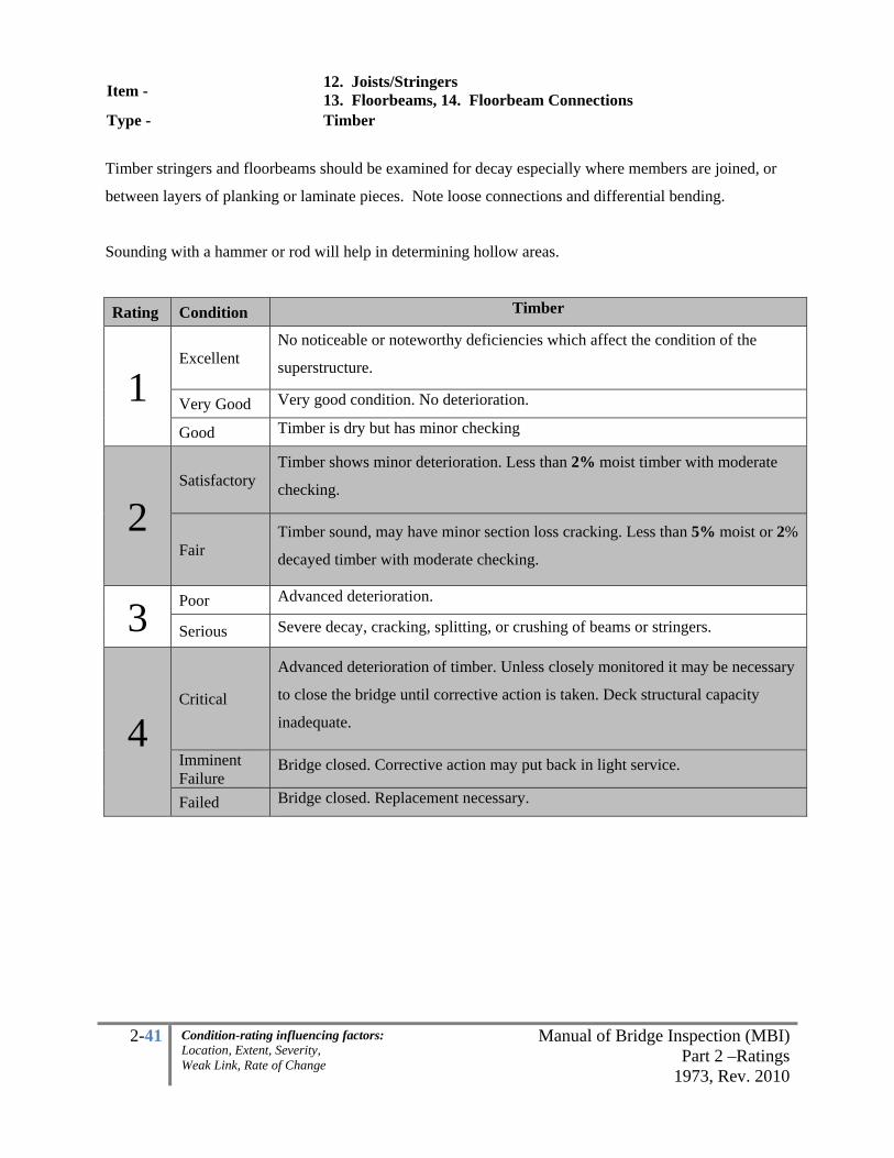
2-41 Manual of Bridge Inspection (MBI)Part 2 –Ratings
1973, Rev. 2010
Condition-rating influencing factors: Location, Extent, Severity, Weak Link, Rate of Change
Item - 12. Joists/Stringers 13. Floorbeams, 14. Floorbeam Connections
Type - Timber
Timber stringers and floorbeams should be examined for decay especially where members are joined, or
between layers of planking or laminate pieces. Note loose connections and differential bending.
Sounding with a hammer or rod will help in determining hollow areas.
Rating Condition Timber
1 Excellent
No noticeable or noteworthy deficiencies which affect the condition of the
superstructure.
Very Good Very good condition. No deterioration.
Good Timber is dry but has minor checking
2 Satisfactory
Timber shows minor deterioration. Less than 2% moist timber with moderate
checking.
Fair Timber sound, may have minor section loss cracking. Less than 5% moist or 2%
decayed timber with moderate checking.
3 Poor Advanced deterioration.
Serious Severe decay, cracking, splitting, or crushing of beams or stringers.
4 Critical
Advanced deterioration of timber. Unless closely monitored it may be necessary
to close the bridge until corrective action is taken. Deck structural capacity
inadequate.
Imminent Failure
Bridge closed. Corrective action may put back in light service.
Failed Bridge closed. Replacement necessary.

2-42 Manual of Bridge Inspection (MBI)Part 2 –Ratings
1973, Rev. 2010
Condition-rating influencing factors: Location, Extent, Severity, Weak Link, Rate of Change
Superstructure
Item - 15. Verticals, 16. Diagonals 17. End Posts, 18. Upper Chord 19. Lower Chord
Type - Any
Primary truss members include Upper Chord, Lower Chord, Vertical and Diagonal members that carry
compressive or tensile forces. This rating will not include zero-force members. Inspect for cracks,
section loss, damage, and pack rust. The inspector shall give special focus to areas with Fatigue Prone
Details.
The inspector should visually inspect all fracture critical (FC) structural members of the bridge within an
"arm's-reach" distance at a minimum of a 24 month interval. Part 1 has more detail and the Appendix has
a FCM/FPD example report and a listing of the AASHTO FPD categories.
Consider measuring and documenting section loss in order to update the load rating; ultrasonic thickness
gauges or other quantitative means are recommended.
Inventory
Item #63 344 34A 343

2-43 Manual of Bridge Inspection (MBI)Part 2 –Ratings
1973, Rev. 2010
Condition-rating influencing factors: Location, Extent, Severity, Weak Link, Rate of Change
Superstructure
Item - 15. Verticals, 16. Diagonals 17. End Posts, 18. Upper Chord 19. Lower Chord
Type - Steel (excluding dummy members) Rating Condition Cracks* Section Loss *
1 Excellent None Very Good Minor localized
Good Minor problems; properly repaired, arrested or retrofitted cracks
10% deep pitting localized. Isolated minor pack rust
2 Satisfactory
Some minor deterioration; Broken welds possible but no cracks in the base metal
10% deep pitting scattered, up to 25% deep localized pitting. Minor pack rust widespread
Fair
Minor cracking (ie. small, stable cracks in base metal in compression zone, cracks in weld metal only)
Minor section loss, up to 10% average section loss in entire cross section perpendicular to the load path; 25% deep widespread pitting, , small corrosion holes may exist in compression members. Significant Pack rust.
3 Poor
Fatigue or out-of-plane bending cracks (ie. cracks, any longer than 2” in compression zone). Note: any crack in the base metal of a FCM parallel to the primary stress shall be “Poor” or less.
Advanced section loss, more than 10% and up to 15% average section loss in entire cross section perpendicular to the load path; 25% deep widespread pitting, , large corrosion hole in compression member, minor corrosion holes may exist in tension member
Serious
Fatigue or out-of-plane bending cracks (ie. several cracks, any longer than 2” in compression zone, or any small crack in tension zone). Note: any crack in the base metal of a FCM perpendicular to the primary stress shall be “Serious” or less.
More than 15% average section loss in cross section perpendicular to the load path; 25% deep widespread pitting, corrosion holes exist in tension member
4 Critical
Advanced deterioration, cracks have removed support or load path in base metal (ex. any longer than 2” in base metal)
Up to 50% connection lost (large corrosion holes, cracked welds, missing rivets/bolts) removing load path
Im. F/Failed Any worse than above * Section loss and cracks are highly dependent on location (ex. corrosion hole below connection
versus between connections), extent severity and rate of change, see following page for spot
measurement %’s. For dormant cracks consideration should be given in increasing the rating.

2-44 Manual of Bridge Inspection (MBI)Part 2 –Ratings
1973, Rev. 2010
Condition-rating influencing factors: Location, Extent, Severity, Weak Link, Rate of Change
Superstructure
Item - 15. Verticals, 16. Diagonals 17. End Posts, 18. Upper Chord 19. Lower Chord
Type - Steel
% Section Loss plate thicknesses
Depth of Section Loss
Original Plate Thickness (in) 1/4 1/2 5/8 3/4
1/16 25% 13% 10% 8% 1/8 50% 25% 20% 17%
3/16 75% 38% 30% 25% 1/4 100% 50% 40% 33%
5/16 corrosion hole
63% 50% 42% 3/8 75% 60% 50%
7/16 88% 70% 58% 1/2 100% 80% 67%
9/16 corrosion hole
90% 75% 5/8 100%
corrosion hole
83% 11/16 92%
3/4 100%
*Section Loss (SL) – For localized point measurements, the above table gives percentages for
thickness reductions due to section loss (or loss of section). Location, extent and severity will
govern the condition rating.

2-45 Manual of Bridge Inspection (MBI)Part 2 –Ratings
1973, Rev. 2010
Condition-rating influencing factors: Location, Extent, Severity, Weak Link, Rate of Change
Superstructure
Item - 15. Verticals, 16. Diagonals 17. End Posts, 18. Upper Chord 19. Lower Chord
Type - Timber
Timber should be examined for decay especially where members are joined, or between layers of
planking or laminate pieces. Note loose connections and differential bending.
Sounding will help in determining hollow areas.
Rating Condition
1 Excellent
No noticeable or noteworthy deficiencies which affect the condition of the
superstructure.
Very Good Very good condition. No deterioration.
Good Timber is dry but has minor checking
2 Satisfactory
Timber shows minor deterioration. Less than 2% moist timber with moderate
checking.
Fair Timber, sound, may have minor section loss cracking. Less than 5% moist or
2% decayed timber with moderate checking.
3 Poor Advanced deterioration.
Serious Severe decay, cracking, splitting, or crushing of beams or stringers.
4 Critical
Advanced deterioration of timber. Unless closely monitored it may be necessary
to close the bridge until corrective action is taken. Deck structural capacity
inadequate. More than 20% connection lost.
Imminent Failure
Bridge closed. Corrective action may put back in light service.
Failed Bridge closed. Replacement necessary.

2-46 Manual of Bridge Inspection (MBI)Part 2 –Ratings
1973, Rev. 2010
Condition-rating influencing factors: Location, Extent, Severity, Weak Link, Rate of Change
Superstructure Item - 20. Gusset Plates (only Truss bridges) Type - Steel
Gusset plates are the vertical plates at a panel point that join generally 3-5 primary members. This item is
not to be used for secondary member gusset plates. In a truss bridge, gusset plates are designed to
transfer member loads that are tensile, compressive or both. It is important to know the nature of the
forces (tensile, compressive or both) and whether these forces will be adequately balanced and can be
safely carried through the gusset plates.
Section loss, cracking and bowing will control the condition rating. A UT Gauge or calipers and a long
straight edge are recommended for use in determining the section properties.
The connectivity exists through fasteners such as rivets or bolts or welds. A critical condition exists
where more than 20% of the connection is lost (note that one plate is equal to 50% of the connection) due
to broken welds, corrosion holes, sheared bolts or rivets.
Because there are two plates at each panel point:
Inboard plate – denotes the plate closer to the centerline of the bridge
Outboard plate – denotes the plate on the outside face or further from the centerline of the bridge
Connection Lost – The above gusset plate connection to the vertical has 4 bolts on each side or 8 total
bolts supplying connection. Where 2 have been sheared or broken then 2/8 or 25% of the connection is
lost because there are two plates. Item 20. Gusset Plates would be coded a 4-Critical (on 1-4 scale)
because more than 20% of the connection is lost. Connection can also be lost due to corrosion holes
and/or cracked welds.
XX

2-47 Manual of Bridge Inspection (MBI)Part 2 –Ratings
1973, Rev. 2010
Condition-rating influencing factors: Location, Extent, Severity, Weak Link, Rate of Change
Superstructure Item - 20. Gusset Plates Type - Steel
Condition Section Loss & Connectivity Structural Bowing*
1 Excellent
Very Good None
Good 10% deep pitting localized Up to 10% of panel points with
1/8”
2
Satisfactory Up to 25% deep localized pitting Up to half of the panel points with
1/8"
Fair
Up to 20% average section loss along one plate
along any **primary line; 25% deep widespread
pitting, isolated pitting deeper than 25%, a
corrosion hole may exist in primary line
Any 1 with
1/4''
3
Poor
At least 35% average section loss along one
plate along any primary line**, corrosion hole
may exist within a primary line. Note: any
crack in the base metal of a FCM parallel to the
primary stress shall be “Poor” or less.
Any 1 with
3/8''
Serious
Up to 20% connection lost (large corrosion
hole(s), cracked welds, missing rivets/bolts)
along any primary line**. Percentage includes
both plates at the pp i.e. 1 plate is 50% of the
connection. Note: any crack in the base metal
of a FCM perpendicular to the primary stress
shall be “Serious” or less.
Any 1 set distributing the same
loaded member (both plates) with
More than 3/8''
4 Critical
Up to 50% connection lost (corrosion holes,
cracked welds, missing rivets/bolts) along any
primary line**. Percentage includes both plates
at the pp i.e. 1 plate is 50% of the connection
Any 1 set per panel point (both
plates) with
More than or equal to 5/8”
Imminent Failure
Any condition worse than above, major deterioration or section loss. Closed to
traffic.
Failed out of service - beyond corrective action

2-48 Manual of Bridge Inspection (MBI)Part 2 –Ratings
1973, Rev. 2010
Condition-rating influencing factors: Location, Extent, Severity, Weak Link, Rate of Change
Superstructure Item - 20. Gusset Plates Type - Steel
*Bowing – This is not to include bowing induced by pack rust or fit-up between members. It shall
include structural induced bowing. Every effort must be taken to compare measurements with the
previous inspection in order to monitor change. Include the measuring procedure in the comments.
**Primary Line –This includes three lines of possible failure and bowing depending on the framing plan
and whether members carry tension, compression or both tension and compression (Drawings below from
FHWA-IF-09-014)
1. Block Shear Rupture
2. Shear on the Gross or Net Section
3. Effective Width
4. Unbraced Length
% Section Loss plate thicknesses
Depth of Section Loss
Original Plate Thickness (in) 1/4 1/2 5/8 3/4
1/16 25% 13% 10% 8% 1/8 50% 25% 20% 17%
3/16 75% 38% 30% 25% 1/4 100% 50% 40% 33%
5/16 corrosion hole
63% 50% 42% 3/8 75% 60% 50%
7/16 88% 70% 58% 1/2 100% 80% 67%
9/16 corrosion hole
90% 75% 5/8 100%
corrosion hole
83% 11/16 92%
3/4 100%
Section Loss (SL) – For localized point measurements, the above table gives percentages for thickness
reductions due to section loss (or loss of section). Location, extent and severity will govern the condition
rating.

2-49 Manual of Bridge Inspection (MBI)Part 2 –Ratings
1973, Rev. 2010
Condition-rating influencing factors: Location, Extent, Severity, Weak Link, Rate of Change
Superstructure Item - 20. Gusset Plates Type - Steel
Block Shear Rupture – 1/6 - Measure along shear and tension planes
and inspect for connectivity of fasteners or welds (FHWA-IF-09-014).
Shear on Gross – 2/6 - Measure along shear planes and inspect
for connectivity of fasteners or welds (FHWA-IF-09-014).

2-50 Manual of Bridge Inspection (MBI)Part 2 –Ratings
1973, Rev. 2010
Condition-rating influencing factors: Location, Extent, Severity, Weak Link, Rate of Change
Superstructure Item - 20. Gusset Plates Type - Steel
Shear on Net – 3/6 - Measure along shear planes and
inspect for connectivity of fasteners or welds (FHWA-IF-09-014).
Effective Width 4/6 - Measure along the effective width from a 30 degree angle from the last row of
connection and inspect for connectivity of fasteners or welds (FHWA-IF-09-014).

2-51 Manual of Bridge Inspection (MBI)Part 2 –Ratings
1973, Rev. 2010
Condition-rating influencing factors: Location, Extent, Severity, Weak Link, Rate of Change
Superstructure Item - 20. Gusset Plates Type - Steel
Effective Width 5/6 - Take thickness measurements along effective width
and inspect for connectivity of fasteners or welds (FHWA-IF-09-014).
Bowing – 6/6 -Inspect for situations where both plates at one panel point are bowed and
also note the unbraced length especially behind compression members (FHWA-IF-09-014).

2-52 Manual of Bridge Inspection (MBI)Part 2 –Ratings
1973, Rev. 2010
Condition-rating influencing factors: Location, Extent, Severity, Weak Link, Rate of Change
Superstructure Item - 21. Lateral Bracing, 22. Sway Bracing
23. Portals (Bracing) Type –
Steel
The secondary system of members distributes loads, stabilizes the bridge against torsional and wind
loadings, prevents buckling of compression chords, and integrates the separate main member systems.
Check all secondary system members for condition, alignment, collision damage, and security of
connection. Note: Lower lateral bracing may also exist on girder type structures. On highly skewed
bridges (> 30 degree) secondary members may control the condition rating.
Bracing types include:
Upper Lateral Bracing (ULB)
Lower Lateral Bracing (LLB)
Sway Bracing (SB)
Portal Bracing (PB)

2-53 Manual of Bridge Inspection (MBI)Part 2 –Ratings
1973, Rev. 2010
Condition-rating influencing factors: Location, Extent, Severity, Weak Link, Rate of Change
Superstructure Item - 21. Lateral Bracing, 22. Sway Bracing
23. Portals (Bracing) Type – All (predominant description is steel)
Condition
Cracking
Connections-welds &
fasteners
Section loss, *damage,
distortion, deflection
Excessive vibration or
tensioning of member
1 Excellent Very Good
Good
Cracks have been
properly retrofitted.
Connectors are tight
and secure.
Minor damage to member. No noticeable vibration
due to wind or live load.
2 Satisfactory
Minor cracks, some
loose connectors. Moderate damage.
Visually noticeable
vibration due to wind or
live load. Audible
evidence of vibration.
Fair Misalignment of member.
Significant vibration
(visual or audible) due
to wind or live load.
3
Poor
Loose connections,
cracks in multiple
members of connectors.
Major damage to tension
member (horizontally
curved superstructure).
Tension rods hanging
slack or sagging or
missing.
Serious
Out of plane distortion in
compression member
(horizontally curved
superstructure). Impact
damage up to 2” to non
adjacent sway bracing.
4 Critical Loss of all members in one transverse plane. Up to 2 bays, non adjacent, missing
bracing. Any worse than above. Imminent Failure Failed
*Verify any changes to the vertical clearance for over height bracing.

2-54 Manual of Bridge Inspection (MBI)Part 2 –Ratings
1973, Rev. 2010
Condition-rating influencing factors: Location, Extent, Severity, Weak Link, Rate of Change
Superstructure Item - 24. Bearing Devices Type - All
Bearing devices transmit the superstructure load to the substructure. They also provide for longitudinal
movement due to expansion and contraction and rotational movement due to deflection. The bridge
bearings are important to the structure. If they are not kept in good working order, stresses may be
induced into the structure that will shorten the usable life of the bridge. Check all components of bearings
for deterioration, movement, alignment, contact and security of connections. Where heightened
monitoring is recommended movement may be tracked using the movable bearing sheet in the Appendix.
While bearing devices may cause serious problems, rarely will the summary condition rating of the
superstructure be reduced because of the bearings. Bearings for trusses and twin girder bridges may be
given full consideration in the superstructure rating due to their lack of redundancy.
Available redundancy will influence the condition ratings. For example, where redundancy exists rarely
will one failed bearing control the whole bearing system when all others are in good condition. Multiple
adjacent bearings overextended or rotated to the point that portions of the superstructure may drop in
elevation may also control the condition rating. Rate bearing devices for semi-integral-type bridges.
Three primary functions
of a movable bearing:
1. Transmit
Superstructure Loads,
2. Allow Rotation,
3. Allow horizontal
movement due to the
change in temperature.

2-55 Manual of Bridge Inspection (MBI)Part 2 –Ratings
1973, Rev. 2010
Condition-rating influencing factors: Location, Extent, Severity, Weak Link, Rate of Change
Superstructure Item - 24. Bearing Devices Type - All
Condition Anchor Bolts, General Deficiencies Multiple Bearings on Adjacent Beams OR Any on Nonredundant structure
1
Excellent No deterioration Bearings are free to move, slide, roll or rock back and forth longitudinally and rotate as designed. Bearings have not moved or shifted vertically or transversely from its intended position.
Very Good Minimal deterioration, dirt and debris
Good Minor pitting, aesthetic deficiencies, dirt and debris building around the bearings.
2
Satisfactory Missing not more than one anchor bolt per substructure unit
Section loss, pack rust, bearings may have shifted vertically or horizontally but is still within the design tolerance. Keeper bars or anchor bars are bent or showing signs of bending, multiple adjacent bearings floating or loose when tapped with hammer. Fair
Missing not more than one anchor bolt per bearing
3 Poor
Missing more than two anchor bolts per substructure unit
Advanced section loss, advanced pack rust, bearings are frozen and no longer free to move, tilted in excessively wrong directions for the temperature or tilted beyond recall*. Keeper bars or anchors are broken from transverse movement
Serious
One interior (not fascia) bearing moved beyond recall*, Any one bearing for an interior beam walked completely out of position
4 Critical Rocked beyond recall*, walked out of position
* Beyond Recall – Rocker(s) measured with a plumb-line
whose horizontal distance is greater than 1/3 of H (Vertical
height difference between the bottom face of the sole plate
(top plate) and the top face of the masonry plate or bottom
plate). Often the rocker will pinch and gouge
into the sole plate and begin to slide rather than
rock.
Plumb Line

2-56 Manual of Bridge Inspection (MBI)Part 2 –Ratings
1973, Rev. 2010
Condition-rating influencing factors: Location, Extent, Severity, Weak Link, Rate of Change
Superstructure Item - 24. Bearing Devices Type - Elastomeric Bearing (Laminated and Plain)
Rating
Loss of Cover & Dislocation Shear Distortion
Shear Delamination
(bulges merge into larger bulge)
1 Excellent Slight bulge, no tearing, splitting or elongation of the elastomer pad. Shear deformations are
correct for existing temperatures; rotation of the bearing is within tolerable limits. Very Good
Good No noticeable bulges, less than or equal to 10% face area. Minor dislocation from sole plate
Minor distortion, uplift Minor bulging within tolerable limits
2 Satisfactory
Minimal bulging, less than or equal to 25% face area. Slipping less than 1/2" on less than 10% of bearings for one substructure unit..
Shear on bearing with deformation greater than 1/2 bearing thickness, minor uplift
Any shear delaminations up to 15% of the pad thickness.
Fair Slipping greater than 1/2" with load plate attached, up to 25% of bearings for one substructure unit.
Shear on two adjacent bearings with deformation greater than 1/2 bearing thickness,
Any one bearing with bulging of at least 15% of the pad’s thickness.
3 Poor
Slipping greater than 1/2" with load plate attached, greater than 25% of bearings for one substructure unit.
Shear on multiple non-adjacent bearings with deformation greater than 1/2 bearing thickness,
Any two adjacent bearings with bulging of 15% of the pad’s thickness.
Serious Slipping greater than 1/2" greater than 50% of bearings for one substructure unit.
Less than 10% of face area any without redundancy.
4 Critical
Multiple bearings have completely walked out of place position, any two bearings on one substructure unit
Shear on multiple adjacent bearings with deformation greater than 1/2 bearing thickness,
Greater than 10% of face area any without redundancy.
Imminent Failure Any condition worse than above. Failed
Longitudinal measurements for the elastomeric bearing are taken with a straight edge or plumb line dropped from the expanded corner and measured horizontally from the bottom of the bearing (dimension ‘m’ shown). Measurements for variable thickness between the front and back and left and right sides should also be taken. These may be compared with ambient temperatures for proper expansion and contraction limitations.

2-57 Manual of Bridge Inspection (MBI)Part 2 –Ratings
1973, Rev. 2010
Condition-rating influencing factors: Location, Extent, Severity, Weak Link, Rate of Change
Superstructure Item - 25. Arch Type – All Arched superstructure spans are vertically curved throughout the length of the span. The curve converts
vertical (gravity) loads within the span to horizontal and vertical thrusts at the spring lines. As a result,
the forces within the arch are generally compression although steel and reinforced concrete arches can
accommodate some bending or tension.
The curve of the arch may be elliptical, parabolic or circular, or may include multiple curves. The curve
should be smooth and continuous. Arch spandrels may be open or filled. Filled spandrel arches are
susceptible to water infiltration into the fill, which may cause wet areas, efflorescence and degradation of
the intrados (interior face of the arch) or the spandrel walls.
Open spandrel arches use columns to transmit the vertical loads to the arch. Through arches are similar to
open spandrel arches except that the vertical loads “hang” from the arch. Rib arch structures use multiple
narrow arches separated laterally, with spandrel walls or columns to transmit the vertical loads to the
arches. Open spandrel arches, arch columns and hangers should be rated similarly to beams and girders
of the same material. Spandrel walls on filled spandrel arches serve to retain the fill.
Filled Arch Nomenclature
Culverts: more than 24” of fill exist and the functioning, roadway railings are not in the same vertical
plane as the headwall. Otherwise the structure is a filled arch. Culverts shall be coded beginning with
item 43 on the BR-86

2-58 Manual of Bridge Inspection (MBI)Part 2 –Ratings
1973, Rev. 2010
Condition-rating influencing factors: Location, Extent, Severity, Weak Link, Rate of Change
Superstructure Item - 25. Arch Type – Filled
Rating
Spalling with Exposed Reinforcement, Delaminations
Damp or Dark Areas (Saturation) Cracking
% of area (include the Severity of fascias within item 27. Spandrel Wall)
1
Excellent No signs of distress, no discoloration
Very Good Minor delaminations, minor spalling
Minor discoloration
Isolated hairline cracking with no rust staining, no dampness, no leakage
Good Up to 1% Up to 5%
Minor problems, hairline cracking with isolated leaking, efflorescence. No rust staining. Map cracking combined with mottled areas up to 5%
2
Satisfactory Up to 5% (unsound areas up to 10%)
Up to 10%Minor structural cracking with leaking, efflorescence and rust staining. Map cracking combined with mottled areas up to 10%
Fair
Up to 10%, (unsound areas up to 20%) slab with more than 1/3 primary bars exposed in one transverse plane
Up to 20%Structural cracking with leaking, efflorescence and rust staining. Map cracking combined with mottled areas up to 20%
3 Poor
Combined total not exceeding 30% with more than 4 adjacent exposed reinforcing bars having greater than 10% section loss to the original diameter.
Advanced cracking with heavy leaking, efflorescence and rust staining. Hairline map cracking combined with mottled areas up to 30%
Serious Up to 30% spalling, delamination with more than 5 adjacent reinforcing bars have greater than 25% section loss to the original diameter OR Up to 50% damp/dark areas
4 Critical
More than 30% spalling, delamination with more than 10 adjacent reinforcing bars having greater than 25% section loss to the original diameter OR More than 50% damp/dark areas; Evidence that full depth hole(s), leading to structural failure of the slab in the traveled lane.
Imminent Failure
Major deterioration in critical structural components or obvious vertical or horizontal movement affecting structure stability. Bridge is closed to traffic but correction action may put back in light service
Failure Bridge closed, collapsed

2-59 Manual of Bridge Inspection (MBI)Part 2 –Ratings
1973, Rev. 2010
Condition-rating influencing factors: Location, Extent, Severity, Weak Link, Rate of Change
Superstructure Item - 25. Arch Type – Masonry Filled
Condition General Displacement
1 Excellent No signs of distress, Minor spalling of stone surface.
Very Good Scaling on of stone surface less than 1/2 inch.
Good Diagonal or vertical shear crack in isolated stones. Fracture of stone surface less than 2 inches.
2 Satisfactory
Diagonal or vertical shear crack through several courses of stone. Removable stone face for less than 1/2 of bridge width less than ¼ stone depth.
Minor
Fair
Diagonal or vertical shear crack through several courses of stone. Removable stone less than ¼ of stone depth for more than 1/2 of bridge
Displacement may be bulge or leaning stones. Total displacement is less than 1/4 of stone depth.
3 Poor
Settlement causing diagonal or vertical shear crack through several courses of stone with displacement. Large fractures or erosion of stone surfaces up to 1/3 stone depth on several adjacent stones.
Total displacement is less than 1/3 of stone depth.
Serious
Large unsound areas. Misalignment of mortar joints. Large fractures or erosion of stone surfaces greater than 1/3 stone depth.
Several stones are displaced or missing.
4 Critical
Numerous missing or displaced stones. Displacements greater than 1/3 of stone depth. Keying (vertical separation between compression stones), or measurable displacement between adjacent stones, exists on at least 3 stones in one longitudinal load-line.
ImmFailure Partially collapsed abutment Failed Total failure of abutment

2-60 Manual of Bridge Inspection (MBI)Part 2 –Ratings
1973, Rev. 2010
Condition-rating influencing factors: Location, Extent, Severity, Weak Link, Rate of Change
Superstructure Item - 25. Arch Type – Deck Arch, Steel - Ribbed Rating Condition Cracks** Section Loss *
1 Excellent None Very Good Minor localized
Good Minor problems; repaired, arrested or retrofitted cracks
10% deep pitting localized. Isolated minor pack rust.
2 Satisfactory
Some minor deterioration; Broken welds possible but no cracks in the base metal
10% deep pitting scattered, up to 25% deep localized pitting. Minor pack rust widespread
Fair
Minor cracking (ie. small, stable cracks in base metal in compression zone, cracks in weld metal only)
Minor section loss, up to 10% average section loss in entire cross section perpendicular to the load path; 25% deep widespread pitting, , small corrosion holes may exist in compression members. Significant pack rust widespread
3 Poor
Fatigue or out-of-plane bending cracks (ie. cracks, any longer than 2” in compression zone). Note: any crack in the base metal of a FCM parallel to the primary stress shall be “Poor” or less.
Advanced section loss, more than 10% and up to 15% average section loss in entire cross section perpendicular to the load path; 25% deep widespread pitting, , large corrosion hole in compression member, minor corrosion holes may exist in tension member
Serious
Fatigue or out-of-plane bending cracks (ie. several cracks, any longer than 2” in compression zone, or any small crack in tension zone). Note: any crack in the base metal of a FCM perpendicular to the primary stress shall be “Serious” or less.
More than 15% average section loss in cross section perpendicular to the load path; 25% deep widespread pitting, corrosion holes exist in tension member
4 Critical
Advanced deterioration, cracks have removed support or load path in base metal (ex. any longer than 2” in base metal)
Up to 50% connection lost (large corrosion holes, cracked welds, missing rivets/bolts) removing load path
Im. F/Failed Any worse than above * Section loss and cracks are highly dependent on location (ex. corrosion hole below connection
versus between connections), extent severity and rate of change, see following page for spot
measurement %’s. For dormant cracks consideration should be given in increasing the rating.

2-61 Manual of Bridge Inspection (MBI)Part 2 –Ratings
1973, Rev. 2010
Condition-rating influencing factors: Location, Extent, Severity, Weak Link, Rate of Change
Superstructure Item - 26. Arch Columns or Hangers Type – Steel
The inspector must visually inspect all fracture critical (FC) structural members of the bridge within an
"arm's-reach" distance at a minimum of 24 months. When FC members exist refer to the Appendix and
Part 1 of this manual for information regarding the inspection of FC structural steel.
Cracking and section loss will dictate the condition rating for steel. Corrosion will be included in the
Protective Coating System (PCS) rating. Consider measuring and documenting section loss to update the
load rating. Discuss changes with the Load Ratings engineer. Ultrasonic thickness gauges or other
quantitative means are highly recommended.
Critical areas may vary depending upon redundancy. Section loss may vary the condition rating
depending on redundancy.
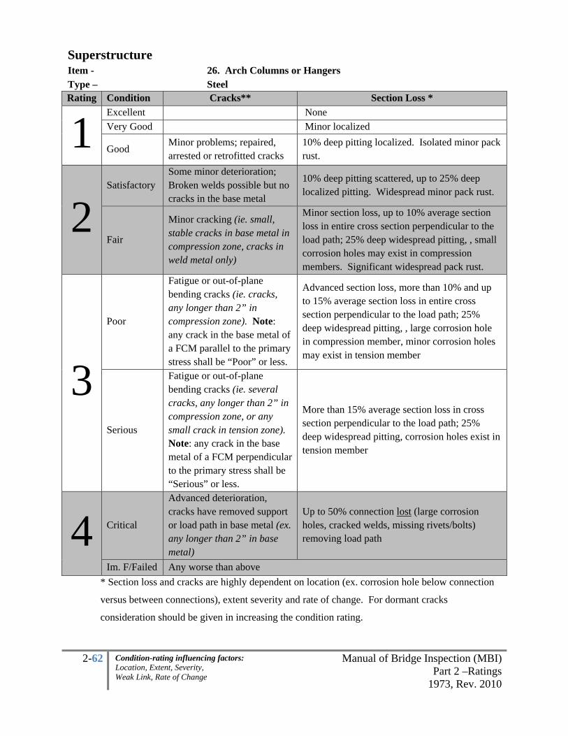
2-62 Manual of Bridge Inspection (MBI)Part 2 –Ratings
1973, Rev. 2010
Condition-rating influencing factors: Location, Extent, Severity, Weak Link, Rate of Change
Superstructure Item - 26. Arch Columns or Hangers Type – Steel Rating Condition Cracks** Section Loss *
1 Excellent None Very Good Minor localized
Good Minor problems; repaired, arrested or retrofitted cracks
10% deep pitting localized. Isolated minor pack rust.
2 Satisfactory
Some minor deterioration; Broken welds possible but no cracks in the base metal
10% deep pitting scattered, up to 25% deep localized pitting. Widespread minor pack rust.
Fair
Minor cracking (ie. small, stable cracks in base metal in compression zone, cracks in weld metal only)
Minor section loss, up to 10% average section loss in entire cross section perpendicular to the load path; 25% deep widespread pitting, , small corrosion holes may exist in compression members. Significant widespread pack rust.
3 Poor
Fatigue or out-of-plane bending cracks (ie. cracks, any longer than 2” in compression zone). Note: any crack in the base metal of a FCM parallel to the primary stress shall be “Poor” or less.
Advanced section loss, more than 10% and up to 15% average section loss in entire cross section perpendicular to the load path; 25% deep widespread pitting, , large corrosion hole in compression member, minor corrosion holes may exist in tension member
Serious
Fatigue or out-of-plane bending cracks (ie. several cracks, any longer than 2” in compression zone, or any small crack in tension zone). Note: any crack in the base metal of a FCM perpendicular to the primary stress shall be “Serious” or less.
More than 15% average section loss in cross section perpendicular to the load path; 25% deep widespread pitting, corrosion holes exist in tension member
4 Critical
Advanced deterioration, cracks have removed support or load path in base metal (ex. any longer than 2” in base metal)
Up to 50% connection lost (large corrosion holes, cracked welds, missing rivets/bolts) removing load path
Im. F/Failed Any worse than above * Section loss and cracks are highly dependent on location (ex. corrosion hole below connection
versus between connections), extent severity and rate of change. For dormant cracks
consideration should be given in increasing the condition rating.

2-63 Manual of Bridge Inspection (MBI)Part 2 –Ratings
1973, Rev. 2010
Condition-rating influencing factors: Location, Extent, Severity, Weak Link, Rate of Change
Superstructure Item - 26. Arch Columns or Hangers Type – Reinforced Concrete
Concrete superstructures should be inspected for cracking, leaching, spalling, saturated areas and other
evidence of deterioration. The extent and severity of delaminations shall be determined (ie. sounding
with a hammer, rod, or chain etc.). These areas should be documented and recorded in order to monitor
changes and correlated with the reflective sides. Exposed primary steel reinforcement should be
measured for reduced diameter to compare with as-built conditions. Reduced section properties should be
noted for a possible reanalysis.
Note the nomenclature for the Open Spandrel Deck Arch

2-64 Manual of Bridge Inspection (MBI)Part 2 –Ratings
1973, Rev. 2010
Condition-rating influencing factors: Location, Extent, Severity, Weak Link, Rate of Change
Superstructure Item - 26. Arch Columns or Hangers Type – Reinforced Concrete
Rating
Spalling with Exposed Reinforcement, Delaminations
Damp or Dark Areas (Saturation) Cracking
% of area (1 column may serve as a “Weak Link”)
1
Excellent No signs of distress, no discoloration
Very Good Minor delaminations, minor spalling
Minor discoloration
Isolated hairline cracking with no rust staining, no dampness, no leakage
Good Up to 1% Up to 5% Minor problems, hairline cracking with isolated leaking, efflorescence. No rust staining.
2 Satisfactory
Up to 5% (unsound areas up to 10%)
Up to 10%Minor structural cracking with leaking, efflorescence and rust staining.
Fair
Up to 10%, (unsound areas up to 20%) slab with more than 1/3 primary bars exposed in one transverse plane
Up to 20% Structural cracking with leaking, efflorescence and rust staining.
3 Poor
Combined total not exceeding 30% with more than 4 adjacent exposed reinforcing bars having greater than 10% section loss to the original diameter.
Advanced cracking with heavy leaking, efflorescence and rust staining.
Serious Up to 30% spalling, delamination with more than 5 adjacent reinforcing bars have greater than 25% section loss to the original diameter OR Up to 50% damp/dark areas
4
Critical
More than 30% spalling, delamination with more than 10 adjacent reinforcing bars having greater than 25% section loss to the original diameter OR More than 50% damp/dark areas; Evidence that full depth hole(s), leading to structural failure of the slab in the traveled lane.
Imminent Failure
Major deterioration in critical structural components or obvious vertical or horizontal movement affecting structure stability. Bridge is closed to traffic but correction action may put back in light service
Failure Bridge closed, collapsed

2-65 Manual of Bridge Inspection (MBI)Part 2 –Ratings
1973, Rev. 2010
Condition-rating influencing factors: Location, Extent, Severity, Weak Link, Rate of Change
Superstructure Item - 27. Spandrel Walls Type – Reinforced Concrete
Rating Spalling with Exposed
Reinforcement, Delaminations
Damp or Dark Areas (Saturation) Cracking and Rotation
% of area
1
Excellent No signs of distress, no discoloration
Very Good Minor delaminations, minor spalling
Minor discoloration
Isolated hairline cracking with no rust staining, no dampness, no leakage
Good Up to 1% Up to 5%
Minor problems, hairline cracking with isolated leaking, efflorescence. No rust staining. Map cracking combined with mottled areas up to 5%
2
Satisfactory
Up to 5% (unsound areas up to 10%) Minor isolated loss of concrete under arch fascia, bearing
Up to 10%
Minor structural cracking with leaking, efflorescence and rust staining. Map cracking combined with mottled areas up to 10%. Minor differential settlement.
Fair
Up to 10%, (unsound areas up to 20%) Minor widespread loss of concrete under arch fascia, bearing
Up to 20%
Structural cracking with leaking, efflorescence and rust staining. Map cracking combined with mottled areas up to 20%. Moderate rotation or settlement
3 Poor
Advanced isolated loss of concrete under arch fascia, bearing. Combined total not exceeding 30% with more than 4 adjacent exposed reinforcing bars having greater than 10% section loss to the original diameter.
Advanced cracking with heavy leaking, efflorescence and rust staining. Hairline map cracking combined with mottled areas up to 30%. Severe settlement.
Serious Significant rotation or settlement. Widespread loss of concrete under arch fascia, bearing Up to 30% spalling, delamination with more than 5 adjacent reinforcing bars have greater than 25% section loss to the original diameter OR Up to 50% damp/dark areas.
4
Critical
More than 30% spalling, delamination with more than 10 adjacent reinforcing bars having greater than 25% section loss to the original diameter OR More than 50% damp/dark areas; Loss of fill, active rotation combined with severe loss of bearing area at the arch fascia.
Imminent Failure
Major deterioration in critical structural components or obvious vertical or horizontal movement affecting structure stability. Bridge is closed to traffic but correction action may put back in light service
Failure Bridge closed, collapsed

2-66 Manual of Bridge Inspection (MBI)Part 2 –Ratings
1973, Rev. 2010
Condition-rating influencing factors: Location, Extent, Severity, Weak Link, Rate of Change
Superstructure Item - 28. Protective Coating System (PCS) Type –
All
The Protective Coating System (PCS) is a 9-0 Condition Rating. The system consists of the primary
means which the superstructure (beams) are protected from the elements. It is imperative that the
condition of the protective film be thoroughly inspected.
Painting/Galvanizing/Metalizing/588 Weathering steel shall be rated in this section. For painted steel
structures, inspector should note type of paint and year painted stenciled on the bridge ends and compare
to pre-printed information on BR-86. Changes should be noted and reported on the Inventory Form after
returning to the office. Do not rate any PCS on Substructure items, Concrete Sealers or Deck items.
However, if any of the items are in need of recoating the inspector is to make note of it in the appropriate
space. These guidelines are intended to be used to access the coating condition during the inspection as
well as upon project completion.
The boxes shall be rated according to the following:
Painted Steel Surfaces
Workmanship Inspection:
Surface preparation must be properly done as specified prior to paint application and should be
rated as workmanship conditions. Application of the primer, intermediate, and finish coatings can
affect the overall quality of the paint system. Workmanship inspection areas should include but
are not limited to:
• Incomplete removal of mill scale or surface corrosion in pitted steel members
• Areas not receiving paint
• Hard-to-reach areas that may have been missed during painting. (Top of cross frames,
inside truss members, behind end dams, etc.)
• Paint Adhesion between coats. Peeling of finish coat
• Grit, from the abrasive cleaning process, is in the paint film or left on the steel members
• Paint thickness applied (total paint thickness should be between 8.5 to 24.5 mills when
spot checking the OZEU paint system)

2-67 Manual of Bridge Inspection (MBI)Part 2 –Ratings
1973, Rev. 2010
Condition-rating influencing factors: Location, Extent, Severity, Weak Link, Rate of Change
Superstructure Item - 28. Protective Coating System (PCS) Type –
All
Degradation Inspection:
The degree of coating failure must be assessed during the inspection. Coating failure is measured
as a percentage of the total surface area. Percentage guidelines are given in the condition scale.
Percentage of paint failures/rust should be noted in the remarks space. Typically a painting
project should not significantly impact the structural steel condition rating if section losses and
pitting are present. Paint failures should include but are not limited to:
• Checking, cracking, wrinkling
• Blistering caused by painted over oil, grease, rust
• Pinpoint rusting
• Peeling paint
• Chalking
• Peeling, cracking, or separation of any caulking
Inspection of Weathering Steel:
The inspection of weathering steel bridges differs from that of painted steel bridge. The entire surface
area of weathering steel is covered in rust. The inspector must distinguish between a protective and non-
protective oxide coating. Slight variations in color and texture are important indicators of non-protective
coating requiring close inspection. Inspector shall note any section loss associated with coating failure in
the appropriate item. (eg.. Item 10-Beams, Item 12-Joist/Stringers)
The oxide film must be tested by tapping or by vigorously wire brushing to determine whether the film is
adhering to the substrate. The oxide film texture may debond in the form of granules, flakes, or laminar
sheets. Physical and visual means are used in conjunction to accurately determine the condition of the
oxide film. New weathering steel require 3 to 5 years to stabilize. An inspector should keep in mind the
year built when evaluating the oxide film. The interior surfaces are likely to exhibit the same color of the
exterior beams, but sheltered from the wind and rain the initial dusty surface is not sweep clean, thus
becoming embedded and leaving a coarse finish.

2-68 Manual of Bridge Inspection (MBI)Part 2 –Ratings
1973, Rev. 2010
Condition-rating influencing factors: Location, Extent, Severity, Weak Link, Rate of Change
Superstructure Item - 28. Protective Coating System (PCS) Type –
All
Workmanship issues shall include exterior surface and bottom flanges of all fascia beams or girders that
are to be left unpainted to remove all traces of asphalt cement, oil, grease, diesel fuel or petroleum
deposits, concrete, and other contaminants. The fascia beams shall be free of mill scale.
Combine FAILED portions with % on page 71 to determine the 9-0 rating. Condition ratings for
weathering steel shall use the visual color table and the texture table below to determine failed areas. The
failed areas shall be applied to the condition ratings table. Bridges with a combination of painted beam
ends or fascia beams shall rate each portion appropriately and combine the failed areas for the total area.
Visual Color Table for Weathering Steel
(Failed portion is highlighted Gray)
Color Film Stage Condition
Yellow-Orange Initial stage of exposure Acceptable
Light Brown Early stage of exposure Acceptable
Chocolate brown to purple brown Development of protective oxide Acceptable
Black Non-protective oxide Failed
Texture Table for Weathering Steel
(Failed portions are highlighted Gray)
Texture Surface Stage Condition
Tightly adherent, capable of
withstanding hammering of vigorous
wire brushing
Protective oxide film Acceptable
Dusty Early stage of exposure Acceptable
Granular Possible development of non-
protective oxide Acceptable
Small flakes, 1/4” diameter Non-protective oxide Failed
Large flakes, ½” diameter Non-protective oxide Failed
Laminar sheets of nodules Non-protective oxide, sever
corrosion Failed

2-69 Manual of Bridge Inspection (MBI)Part 2 –Ratings
1973, Rev. 2010
Condition-rating influencing factors: Location, Extent, Severity, Weak Link, Rate of Change
Superstructure Item - 28. Protective Coating System (PCS) Type –
All
Critical structural member/zone
Critical structural member or areas such as 1) pin and hanger connections, 2) steel pier caps, or 3) similar
fracture critical members may govern the paint rating. In such cases use the examples below to assess the
paint condition. The inspector shall note on the inspection report form which item governed the condition
rating.
1) Pin/Hanger/Hinges - 2’-0” on each side of
the center shall be considered as the total area in the
condition rating guide lines. Document in the
comments section if the assemblies control the
condition rating.
2) Steel Pier Caps - The area of the pier cap
plus 1’-0” on each side of the flange edges
shall be considered as the total area in the
condition rating guide lines. Document in
the comments section if the steel pier caps
control the condition rating.
3) Fracture Critical Members – Because these
are a “weak link” one member’s % of failed
PCS may control the 9-0 rating. Document
in the comments section if the steel pier
caps control the condition rating.
4’

2-70 Manual of Bridge Inspection (MBI)Part 2 –Ratings
1973, Rev. 2010
Condition-rating influencing factors: Location, Extent, Severity, Weak Link, Rate of Change
Superstructure Item - 28. Protective Coating System (PCS) Type –
All
Rating
Degradation Problems Workmanship Problems Candidate
for
Recoating
% Surface
Area (SA)
Failed
Issues Surface
Corrosion
% SA
Failed Issues
% Finish
Coat Loss
9 none PCS Sound No
Evidence None
8 Up to 1% PCS Sound Isolated,
Chalking
Up to
5% Isolated
7 Up to 5% PCS Sound Light Up to
10% Multiple
Up to 10%
finish coat
failed Candidate
for zone
painting
(fascias
and under
joints)
6 Up to 10%
Not effective
at Beam ends
under joints
Prevalent Up to
15%
More than
10% finish
coat failed
5 Up to 15%
Not effective
at Beam ends
under joints
Prevalent Up to
20%
4 Up to 20% Not effective Prevalent Large areas of old
Paint Painted over
Candidate
for total
recoating
3 Up to 30%
Any condition worse than above 2 Up to 40%
1 Up to 50%
0- > 50%
* WRITE IN THE COMMENTS IF 1) PIN/HANGER/HINGERS, 2) STEEL PIER CAPS OR 3) A
FRACTURE CRITICAL MEMBER CONTROLLED THE % FOR THE 9-0 RATING.

2-71 Manual of Bridge Inspection (MBI)Part 2 –Ratings
1973, Rev. 2010
Condition-rating influencing factors: Location, Extent, Severity, Weak Link, Rate of Change
Superstructure Item - 29. Pins/Hangers/Hinges Type –
Steel
Inspect all pins, pins and hangers, and seated hinges for evidence of freedom of movement. Check for
pack rust which would limit movement and section loss around support areas. Check alignment of the
adjoining members. Be particularly cognizant of pack rust developing between the hangers and the
beam/girder webs. Also look for evidence of pin and/or hanger wear and loosening of keeper plates or
nuts. This Item may also be used to code the condition of pins in trusses.
UT technology is helpful in finding internal flaws within
the pins and in determining the thickness of the hanger
plates. Take and compare dimensions at a set interval to
monitor the rate of change and to verify if the system is
functioning with the design parameters. Note and measure
any horizontal (diagram to left), vertical, or torsional
misalignment
Beyond Recall – movable bearing(s) measured with a
plumb-line whose horizontal distance is greater than 1/3 of
H (Vertical height difference between the bottom
face of the sole plate (top plate) and the top face
of the masonry plate or bottom plate)
Consider using the “Pin and Hanger Detailed
Inspection Form” in the Appendix for monitoring
movements.
Beam-ends 2-feet on either side of the hanger
or hinge assembly shall be included in this
rating, 29. Pins/Hangers/Hinges. Use the Steel
Beam item 10 rating for guidance in rating the
beams.
4’

2-72 Manual of Bridge Inspection (MBI)Part 2 –Ratings
1973, Rev. 2010
Condition-rating influencing factors: Location, Extent, Severity, Weak Link, Rate of Change
Superstructure Item - 29. Pins/Hangers/Hinges Type - Steel
Rating Condition Functional
Movement Corrosion & Cleanliness Bearing Integrity/Hinge
1 Excellent
Very Good
Good Aesthetic deficiencies only All in proper contact
2
Satisfactory
Movement not
restricted; shallow
wear grooves (up
to 1/8”)
Minor pack rust or debris,
some dry spots in
lubricated parts.
One pin/hanger/hinge slightly
misaligned with others or
missing not more than one
anchor bolt per hanger line
Fair
Movement
restricted only at
extreme operating
limits. Minor
misalignment. At
least 1/8” deep
wear grooves
Moderate pack rust or
accumulated debris.
Moderate abrasion with no
lubricant on parts.
One not in proper contact or
somewhat misaligned with
others. Multiple may be not in
proper contact but only
“floating”. Missing not more
than one anchor bolt per
bearing.
3 Poor
Movement
restricted within
normal operating
limits; seized. Up
to 1” misalignment
Major pack rust or
accumulated debris
limiting normal operation.
Lack of normal operation.
Abrasion >1/8” deep of
hanger sides with no
lubrication.
Multiple not in proper contact
or multiple adjacent
pin/hanger/hinges misaligned
on one unit or multiple not
aligned
Serious Seized due to corrosion or debris, preventing
movement. Up to 2” misalignment
Pin/hanger/hinges leaning
beyond recall or jammed
significantly
4 Critical
Unless closely monitored it may be necessary to close bridge due to advanced
deterioration. Crushing. More than 2” misalignment.
Imminent Failure Any condition worse than above, fatigue crack in base metal Failed

2-73 Manual of Bridge Inspection (MBI)Part 2 –Ratings
1973, Rev. 2010
Condition-rating influencing factors: Location, Extent, Severity, Weak Link, Rate of Change
Superstructure Item - 30. Fatigue Prone Connections Type –
Steel – E & E’ Details (per AASHTO, see FPD table in Appendix for further detail)
Inspect specific E and E’ Fatigue Prone Details for cracks. A typical Ohio DOT Fatigue Prone Detail
(FPD) on or over the interstate system exists on the steel beams continuous over piers with the butt-
welded web and top and bottom fillet-welded cover plates. Inspect these welded areas for fatigue cracks
and code accordingly. Other common E&E’ FPD’s include plug welds, tack welds, tri-axial welds etc.
Where E and E’ FPD’s exist code this condition rating as it directly affects the load path through
the primary members. For example, a cracked E’ weld may be broken off at the primary member and
will not propagate into the primary load path, therefore keep the rating a 1. Photo examples of cracked E
and E’ FPD’s include, from left to right (1. Radiused connection, 2. Splice over pier, 3. Toe of cover plate
weld crack propagated through member, 4. Lateral bracing gusset, 5. Triaxial weld and 6. Cover plate
crack is only through the weld):
1. 2.
4. 5. 6.
Note: Any crack in the base metal of a FCM perpendicular to the primary stress shall be “Serious” or less
and any crack in the base metal of a FCM parallel to the primary stress shall be “Serious” or less. Prompt
interim action is recommended for any crack in a fracture critical member or major impact damage in a
primary member. For dormant cracks consideration should be given in increasing the condition rating.
However, caution should be taken because brittle fractures can occur. Additional factors such as heat
straightening, temperature, length of growth, location, type of detail and number of cycles (AADTT) may
influence the team leader’s judgment.
4.

2-74 Manual of Bridge Inspection (MBI)Part 2 –Ratings
1973, Rev. 2010
Condition-rating influencing factors: Location, Extent, Severity, Weak Link, Rate of Change
Item - 30. Fatigue Prone Connections Type –
Steel – E & E’ Details (per AASHTO, see FPD table in Appendix for further detail)
Rating Condition Cracks in the E or E’ Detail
1 Excellent Very Good
Good Minor problems outside of primary load path; repaired, arrested or retrofitted cracks
2 Satisfactory Minor problems in detail within the load path; repaired, arrested or retrofitted
cracks
Fair Some minor deterioration to detail in primary load path; Broken welds possible but no cracks in the base metal
3 Poor Minor cracking (ie. small, stable cracks in base metal in compression zone,
cracks in weld metal only)
Serious Fatigue or out-of-plane bending cracks (ie. cracks, any longer than 2” in compression zone)
4 Critical Fatigue or out-of-plane bending cracks (ie. several cracks, any longer than 2” in
compression zone, or any small crack in tension zone).
Im. F/Failed Advanced deterioration, cracks have removed support or load path in base metal (ex. any longer than 2” in base metal)
Category E and E' Includes details that have the lowest fatigue strength in comparison to those in
other categories. Generally, for welded details in this group with the same configurations, Category E'
applies if the flange plate thickness exceeds 0.8 inch or if the attachment plate thickness is 1 inch or more.
• Splice welded web/flange over piers (typical ODOT detail from 1950’s).
• Ends of partial length cover plates on girder or beam flanges.
• Welded attachment, with groove or fillet weld in the direction of the main members,
more than 4 inches or 12 times the plate thickness.
• Welded attachment with curved transition radius.
• Welded attachment with loads transverse to welds.
• Intermittent fillet welds
• Shear stress on the throat of a fillet weld (Formerly classified Category F)
• Deck plate at the connection to floorbeam web.
Of all the details, those in Categories E and E’ are the most susceptible to fatigue crack growth. These
details should be inspected at every inspection.

2-75 Manual of Bridge Inspection (MBI)Part 2 –Ratings
1973, Rev. 2010
Condition-rating influencing factors: Location, Extent, Severity, Weak Link, Rate of Change
Superstructure Item - 31. Live Load Response Type – All
This rating is not to be used for ride-quality of the traveling public. It is rather intended to track the
primary member’s response and deflection under live load truck impact.
E Excessive
• This is unfavorable movement (while standing or parked on the wearing surface) due to deflection of the primary structural members.
• Under truck traffic at least one primary superstructure member
noticeably deflects In or out of plane. LRFD Criteria has the following limits, when a rating is in question these may be followed. Excessive movement is any deflection more than the following:
o Span length / 375 for cantilever arms o Span length /800 for bridges without sidewalks o Span length /1000 for bridges with sidewalks
example: 100-ft span without sidewalks noticeably deflects 1-1/4”. The allowable deflection is 100’/800 =0 .125’ or 1.5”, therefore it is not E-excessive by design.
• Longitudinal cracks in the wearing surface exist above all of the
prestressed box beam grout keys indicating independent beam action OR at least one full length wide crack in the traveling lane.
S Satisfactory
• Under truck traffic superstructure member(s) move or deflect but it is within the design limits or not an unfavorable movement to the inspector.
• The LRFD Criteria list above may also be followed when a movement is in doubt.
Note:
• If the Superstructure bearings are “floating” rate the deficiency under item 24. Bearing Devices.
Do not use this item 31. Live Load Response for floating bearings.
• Generally, culverts under more than 8-feet of fill do not receive live load per AASHTO, however
code this item accordingly nonetheless.

2-76 Manual of Bridge Inspection (MBI)Part 2 –Ratings
1973, Rev. 2010
Condition-rating influencing factors: Location, Extent, Severity, Weak Link, Rate of Change
Superstructure Item - 32. SUMMARY Type – All SUPERSTRUCTURE
9. Alignment of Members 10. Beams/Girders/Slab
11. Diaphragms or Cross frames 12. Joists/Stringers
13. Floorbeams 14. Floorbeam Connections
15. Verticals 16. Diagonals
17. End posts 18. Top Chord
19. Lower Chord 20. Gusset Plates
21. Lateral Bracing 22. Sway Bracing 23. Portals 24. Bearing Devices
25. Arch 26. Arch Columns or Hangers
27. Spandrel Walls 28. Protective Coating System (PCS)
29. Pins/Hangers/Hinges 30. Fatigue Prone Detail (E, E’)
31. Live Load Response (E or S) 32. SUMMARY Note: 1-4 Individual Items % are based on the WORST SPAN while the 9-0 Summary Items % are based
on the item throughout the TOTAL BRIDGE (Unless a WEAK LINK is controlling). Therefore the 9-0
rating will, in some cases where 1 span is considerably worse than the entire bridge, be higher than the
conversion below. Bearing Devices may control the summary in extreme circumstances where, for
example, redundancy does not exist or failure would result in a large elevation change. Buckling
diaphragms and cross frames may control for high skewed or horizontally curved steel superstructures.
1-4 INDIVIDUAL 9-0 SUMMARY
1 9-Excellent
8-Very Good
7-Good
2 6-Satisfactory
5-Fair
3 4-Poor
3-Serious
4 2-Critical
1-Im. Failure
0-Failed


2-77 Manual of Bridge Inspection (MBI)Part 2 –Ratings
1973, Rev. 2010
Condition-rating influencing factors: Location, Extent, Severity, Weak Link, Rate of Change
SUBSTRUCTURE
The substructure is that portion of the bridge below the superstructure including the pier and abutment
seats, footings and piling. The substructure transmits the loads and stresses from the deck, superstructure,
or other load supporting system, to the ground.
All exposed or readily accessible portions of the substructure will be inspected at close range. Underwater
investigation will be done to assure that scour and undermining is not threatening the bridge. This will
consist of probing in relatively shallow water and diving in deeper water. Diving inspections will be
performed at least once every 5 years on bridges where the low-water depth prohibits visual or probing
inspections (substructure units in water deeper than 5-feet).
Mechanically Stabilized Earth (MSE) walls may be found as components of the substructure system.
Generally these will serve as Wingwalls and/or Slope Protection (also embankment for the Approach
item). They shall be rated as abutments when the foundation type is spread footing within the MSE wall
(verify with plans or inventory). Backwalls may control the Summary only in extreme situations (eg.
large void under approach due to fill spilling through backwall).
All gray boxes below are not 1-4 ratings. Note: 1-4 Individual Items % are based on the WORST SPAN
while the 9-0 Summary Items % are based on the item throughout the TOTAL BRIDGE.
SUBSTRUCTURE
33. Abutments 34. Abutment Seats 35. Piers 36. Pier Seats 37. Backwalls 38. Wingwalls 39. Fenders and Dolphins 40. Scour (Insp Type – 1, 2, 3)
41. Slope Protection 42. SUMMARY

2-78 Manual of Bridge Inspection (MBI)Part 2 –Ratings
1973, Rev. 2010
Condition-rating influencing factors: Location, Extent, Severity, Weak Link, Rate of Change
Substructure Item - 33. Abutments Type – All
An abutment is the substructure unit located at the ends of a bridge. Its function is to provide end support
for the bridge and to retain the approach embankment. Always rate what you see AND allow
indications of deficiencies to influence a lower condition rating when the unseen item is directly
affected. The seats are the horizontal face on which the bearings transfer load and may include the first
4-6” of the vertical face or cap if under the bearing area (generally 45 degree angle away from the load
path). Do not rate seats for slabs, rigid frames and integral abutments.
The most common problems observed during the inspection of abutments are:
1. Vertical movement
2. Lateral movement
3. Rotational movement
4. Material defects
5. Scour of the foundation
6. Drainage system malfunction
Integral Abutments Do not have bearings or abutment seats. Although structurally it is a part of the
superstructure, for the purposes in filling out the BR-86, consider the backwall the portion above the
horizontal form line. The abutment is below the bottom flange of the beam.
Semi-Integral Abutments – Although structurally it is a part of the superstructure, for the purposes in
filling out the BR-86, Consider the backwall the portion above the horizontal form line. The abutment is
below the form line or polystyrene. Bearings should be rated for semi-integral.
Piers (item 35) are intermediate supports on a multi-span structure. The seats are the horizontal face on
which the bearings transfer load and may include the first 4-6” of the vertical face or cap. Examine for
condition, movement or settlement, and scour.
Steel pier caps (item 35) may be fracture critical members, when only 2 or 3 bents exist, and shall be
reported and inspected as such.
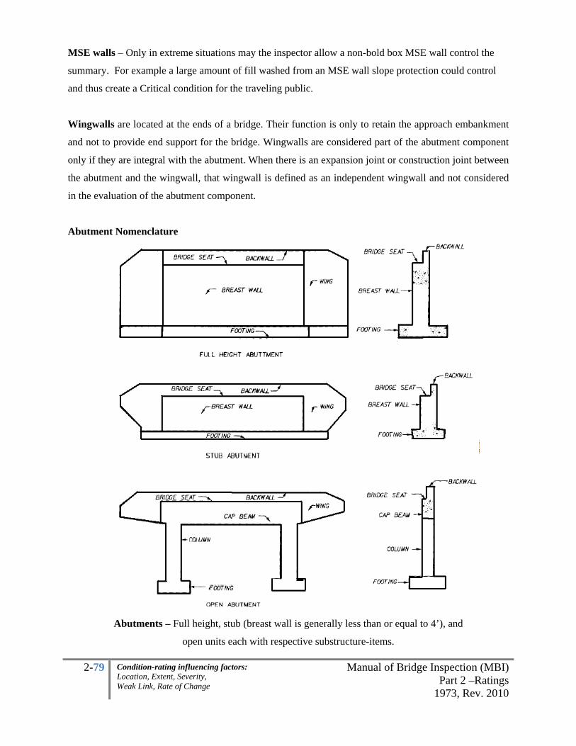
2-79 Manual of Bridge Inspection (MBI)Part 2 –Ratings
1973, Rev. 2010
Condition-rating influencing factors: Location, Extent, Severity, Weak Link, Rate of Change
MSE walls – Only in extreme situations may the inspector allow a non-bold box MSE wall control the
summary. For example a large amount of fill washed from an MSE wall slope protection could control
and thus create a Critical condition for the traveling public.
Wingwalls are located at the ends of a bridge. Their function is only to retain the approach embankment
and not to provide end support for the bridge. Wingwalls are considered part of the abutment component
only if they are integral with the abutment. When there is an expansion joint or construction joint between
the abutment and the wingwall, that wingwall is defined as an independent wingwall and not considered
in the evaluation of the abutment component.
Abutment Nomenclature
Abutments – Full height, stub (breast wall is generally less than or equal to 4’), and
open units each with respective substructure-items.

2-80 Manual of Bridge Inspection (MBI)Part 2 –Ratings
1973, Rev. 2010
Condition-rating influencing factors: Location, Extent, Severity, Weak Link, Rate of Change
Integral and Semi-Integral Abutments
Integral Abutments - Do not have bearings, abutment seats. Consider the backwall the portion above
the horizontal form line. The abutment is below the bottom flange of the beam.
Semi-Integral Abutments – Consider the backwall the portion above the horizontal form line. The
abutment is below the form line or polystyrene. Bearings should be rated for semi-integral. Inspect what you see AND allow indications of deficiencies to influence a lower condition rating when the unseen item
is directly affected. Inspect may have to remove portions when rating is in question.
Although structurally it is a part of the superstructure, for the purposes in filling out the BR-86, consider above the form-line the “backwall” when filling out the BR-86
Although structurally it is a part of the superstructure, for the purposes in filling out the BR-86, consider above the form-line the “backwall” when filling out the BR-86

2-81 Manual of Bridge Inspection (MBI)Part 2 –Ratings
1973, Rev. 2010
Condition-rating influencing factors: Location, Extent, Severity, Weak Link, Rate of Change
Substructure Item - 33. Abutments Type – Full Height Concrete (see next page for Concrete STUB Abutments)
Rating Spalling with Exposed
Reinforcement
Damp or Dark Areas (Saturation) Cracking and Rotation
% of area
1
Excellent No signs of distress, no discoloration
Very Good Minor delaminations, minor spalling
Minor discoloration
Isolated hairline cracking with no rust staining, no dampness, no leakage
Good Up to 1% Up to 5% Minor problems, hairline cracking with isolated leaking, efflorescence. No rust staining.
2 Satisfactory
Up to 5% (unsound areas up to 10%)
Up to 10%Minor structural cracking with leaking, efflorescence and rust staining.
Fair Up to 10% (unsound areas up to 20%)
Up to 20%Structural cracking with leaking, efflorescence and rust staining. Measurable, minor rotation or settlement
3 Poor
Combined total not exceeding 30% with more than 4 adjacent exposed reinforcing bars having greater than 10% section loss to the original diameter.
Advanced cracking with heavy leaking, efflorescence and rust staining. Differential settlement up to 1”
Serious Up to 30% spalling, delamination with more than 5 adjacent reinforcing bars have greater than 25% section loss to the original diameter OR Up to 50% damp/dark areas, significant differential settlement (up to 2” vertical, or up to 4” horizontal)
4
Critical
More than 30% spalling, delamination with more than 10 adjacent reinforcing bars having greater than 25% section loss to the original diameter OR More than 50% damp/dark areas;. Extreme settlement (greater than 2” vertical or greater than 10% of the height; horizontal movement up to 4” max). Any adjacent vertical bars bent or cracked or severed
Imminent Failure
Major deterioration in critical structural components or obvious vertical or horizontal movement affecting structure stability. Bridge is closed to traffic but correction action may put back in light service.
Failure Bridge closed, collapsed

2-82 Manual of Bridge Inspection (MBI)Part 2 –Ratings
1973, Rev. 2010
Condition-rating influencing factors: Location, Extent, Severity, Weak Link, Rate of Change
Substructure Item - 33. Abutments Type –
STUB Abutment use in conjunction with Concrete “Cracks” column on previous page
Condition Spalls/Unsound areas
1
Excellent No spalls.
Very Good No dampness, no leakage, no spalling, no reinforcement visible.
Good A few spalls or unsound areas, some cover missing, exposed reinforcement visible, less
than ½ width of one substructure unit.
2 Satisfactory Up to 4” deep spall for less than 1/2 of bridge width.
Fair Up to 4” deep spall for more than 1/2 of bridge width OR 100% saturation with full
width delaminations with a few exposed vertical bars.
3
Poor
Up to 6” deep spall for more than 1/2 of bridge width; reinforcing bars have extensive
section loss (greater than 10% of original diameter) for more than 4 adjacent bars OR
100% saturation with full width delaminations with many exposed vertical bars.
Serious Up to 8” deep spall for more than 1/2 of bridge width; reinforcing bars have extensive
section loss (greater than 20% of original diameter) for more than 5 adjacent bars.
4
Critical
Up to 8-9” deep spall for more than 1/2 of bridge width; reinforcing bars have extensive
section loss (greater than 30% of original diameter) for more than 10 adjacent bars OR
Bent or broken adjacent vertical bars. Any section under traveled lane where approach
backfill is spilling through.
Imminent Failure/Failed
More than 9” deep spall for more than 1/2 of bridge width; reinforcing bars have
extensive section loss (greater than 30% of original diameter) for more than 10
adjacent bars OR Bent or broken adjacent vertical bars. Any section under traveled lane
where approach backfill is spilling through.

2-83 Manual of Bridge Inspection (MBI)Part 2 –Ratings
1973, Rev. 2010
Condition-rating influencing factors: Location, Extent, Severity, Weak Link, Rate of Change
Substructure Item - 33. Abutments Type – Masonry
Condition General Displacement
1 Excellent No signs of distress, Minor spalling of stone surface.
Very Good Scaling on of stone surface less than 1/2 inch.
Good Diagonal or vertical shear crack in isolated stones. Fracture of stone surface less than 2 inches.
2 Satisfactory
Diagonal or vertical shear crack through several courses of stone. Removable stone face for less than 1/2 of bridge width less than ¼ stone depth.
Minor
Fair
Diagonal or vertical shear crack through several courses of stone. Removable stone less than ¼ of stone depth for more than 1/2 of bridge
Displacement may be bulge or leaning stones. Total displacement is less than 1/4 of stone depth.
3 Poor
Settlement causing diagonal or vertical shear crack through several courses of stone with displacement. Large fractures or erosion of stone surfaces up to 1/3 stone depth on several adjacent stones.
Total displacement is less than 1/3 of stone depth.
Serious
Large unsound areas. Misalignment of mortar joints. Large fractures or erosion of stone surfaces greater than 1/3 stone depth.
Several stones are displaced or missing.
4 Critical
Numerous missing or displaced stones. Displacements greater than 1/3 of stone depth. Keying (vertical separation between compression stones), or measurable displacement between adjacent stones, exists on at least 3 stones in one longitudinal load-line.
ImmFailure Partially collapsed abutment Failed Total failure of abutment

2-84 Manual of Bridge Inspection (MBI)Part 2 –Ratings
1973, Rev. 2010
Condition-rating influencing factors: Location, Extent, Severity, Weak Link, Rate of Change
Substructure Item - 33. Abutments (consider MSE the abutment when the foundation is
spread footing) Type – MSE Walls
Condition Panels Joints Erosion Bowed
1
Excellent No Cracking or
Spalls Uniform joint spacing
Very Good
No Cracking or
Spalls, cracks may
exist in coping
minor variation in joint
spacing None
Good Hairline cracking or
spalls
Moderate variation in joint
spacing, minor sand in
joints
Minor
2 Satisfactory
Cracks <1/4" on a
few panels
Moderate sand in joints
but no exposed fabric nor
sand piles below joints
Minor erosion
along panels, max
1’ deep
Moderate
Fair
Cracks <1/4" many
panels, global,
minor spalling
Exposed fabric at a few
isolated joints, small sand
pile
Moderate erosion
along panels, max
2' deep
Moderate
change since
as built
3
Poor
Cracks >1/4",
global, moderate
spalling
Exposed fabric at many
joints, sand pile(s) below
at least one joint, trees
growing between joints
Erosion >2' deep
along panels
Major
change since
as built
Serious Spalling exposes
backfill
Exposed fabric and active
sand piles below many
joints
Erosion exposing
the top of the
leveling pad and
pad is not on rock,
exposed straps or
mesh
Major,
changing,
global
4 Critical
Any worse than
above
Major leaking of sand
from joints
erosion
undermining
leveling pads
Major,
changing,
systemic and
global
ImmFailure Failed

2-85 Manual of Bridge Inspection (MBI)Part 2 –Ratings
1973, Rev. 2010
Condition-rating influencing factors: Location, Extent, Severity, Weak Link, Rate of Change
Substructure Item - 34. Abutment Seats Type –
All (predominant description is concrete)
The seats are the shelf or the horizontal face on which the bearings transfer load and may include the first
4-6” down the vertical face or cap under the bearing area. Rate the deficiencies below the masonry plates
of the bearings and above the top 4”-6” of the abutment within this item.
Emphasis shall be given to those areas directly under the bearings and at a 45 degree angle away from
each bearing. Do not allow deterioration between beams outside of the load path to influence the
condition rating. Do not rate seats for slabs, rigid frames and integral abutments.
Elevation View – Vertical settlement of the bridge may first be reflected in the joint but may be the sign
of a more critical condition. In this case a cracking of the abutment seat.

2-86 Manual of Bridge Inspection (MBI)Part 2 –Ratings
1973, Rev. 2010
Condition-rating influencing factors: Location, Extent, Severity, Weak Link, Rate of Change
Substructure Item - 34. Abutment Seats Type –
All (predominant description is concrete)
• Redundant: Structures with more than 3 primary lines (ie. beams, girders, truss lines) or in other
words there are more than three bearings transferring the load path at each substructure unit per span.
• Nonredundant: Structures with 2 or 3 primary lines; there are two or three bearings transferring the
load path at each substructure unit per span.
Loss of Bearing Area Cracking
1 Excellent None No Cracks.
Very Good Minor spalling/delamination up to fascia bearings for redundant structure.
Hairline cracking, up to 1/16 wide with no rust staining, no dampness
Good Aesthetic deficiencies, minor spalling, delaminations. Minor loss under fascia bearings for redundant structure.
Hairline cracking, single crack greater than 1/16 without rust staining.
2
Satisfactory
Redundant: Spalling or delaminations up to masonry plate(s) but no undermining to interior beams. Minor undermining is possible under a fascia masonry plate. Nonredundant: Minor spalling, delaminations, no undermining.
Transverse cracks, some leaking. Hairline map cracking combined with mottled areas, cracks up to 1/8” wide with minor efflorescence or leakage.
Fair
Redundant: Fascia bearing loss up to 50%, interior bearings have spalling or delaminations under small portions of the masonry plates. Nonredundant: Spalling or delaminations up to masonry plate but no undermining.
Map cracking, structural cracks up to 1/8 inch wide with efflorescence and/or rust stain, leakage and mottled areas.
3 Poor
Redundant: One interior bearing loss up to 50%, at least two on one substructure unit up to 20% loss. Nonredundant: Spalling undermining portions of masonry plate.
Advanced cracking for example structural cracks wider than 1/8” wide with heavy leaking, efflorescence and staining.
Serious Redundant: At least two adjacent interior masonry plates on one substructure unit more than 20% loss. Nonredundant: Spalling undermining portions of masonry plate up to 20% of area.
4 Critical Any condition worse than above, crushing of steel cap under adjacent interior beams.
Redundant: Interior beams with loss up to 50%. Nonredundant: Spalling undermining portions of masonry plate more than 20% of area.
Imm/ Failure

2-87 Manual of Bridge Inspection (MBI)Part 2 –Ratings
1973, Rev. 2010
Condition-rating influencing factors: Location, Extent, Severity, Weak Link, Rate of Change
Substructure Item - 35. Piers Type – Concrete
Rating Spalling with Exposed
Reinforcement
Damp or Dark Areas (Saturation) Cracking
% of area
1
Excellent No signs of distress, no discoloration
Very Good Minor delaminations, minor spalling
Minor discoloration
Isolated hairline cracking with no rust staining, no dampness, no leakage
Good Up to 1% Up to 5% Minor problems, hairline cracking with isolated leaking, efflorescence. No rust staining.
2 Satisfactory
Up to 5% (unsound areas up to 10%)
Up to 10%Minor structural cracking with leaking, efflorescence and rust staining.
Fair Up to 10 (unsound areas up to 20%)
Up to 20%Structural cracking with leaking, efflorescence and rust staining. Measurable, minor rotation or settlement
3 Poor
Combined total not exceeding 30% with more than 4 adjacent exposed reinforcing bars having greater than 10% section loss to the original diameter.
Advanced cracking with heavy leaking, efflorescence and rust staining. Differential settlement up to 1”
Serious Up to 30% spalling, delamination with more than 5 adjacent reinforcing bars have greater than 25% section loss to the original diameter OR Up to 50% damp/dark areas, significant differential settlement (up to 2” vertical, or up to 4” horizontal)
4
Critical
More than 30% spalling, delamination with more than 10 adjacent reinforcing bars having greater than 25% section loss to the original diameter OR More than 50% damp/dark areas;. Extreme settlement (greater than 2” vertical or greater than 10% of the height; horizontal movement up to 4” max). Any adjacent vertical bars bent or cracked or severed
Imminent Failure
Major deterioration in critical structural components or obvious vertical or horizontal movement affecting structure stability. Bridge is closed to traffic but correction action may put back in light service.
Failure Bridge closed, collapsed

2-88 Manual of Bridge Inspection (MBI)Part 2 –Ratings
1973, Rev. 2010
Condition-rating influencing factors: Location, Extent, Severity, Weak Link, Rate of Change
Substructure Item - 35. Piers Type – Masonry
Condition General Displacement
1 Excellent No signs of distress, Minor spalling of stone surface.
Very Good Scaling on of stone surface less than 1/2 inch.
Good Diagonal or vertical shear crack in isolated stones. Fracture of stone surface less than 2 inches.
2 Satisfactory
Diagonal or vertical shear crack through several courses of stone. Removable stone face for less than 1/2 of bridge width less than ¼ stone depth.
Minor
Fair
Diagonal or vertical shear crack through several courses of stone. Removable stone less than ¼ of stone depth for more than 1/2 of bridge
Displacement may be bulge or leaning stones. Total displacement is less than 1/4 of stone depth.
3 Poor
Settlement causing diagonal or vertical shear crack through several courses of stone with displacement. Large fractures or erosion of stone surfaces up to 1/3 stone depth on several adjacent stones.
Total displacement is less than 1/3 of stone depth.
Serious
Large unsound areas. Misalignment of mortar joints. Large fractures or erosion of stone surfaces greater than 1/3 stone depth.
Several stones are displaced or missing.
4 Critical
Numerous missing or displaced stones. Displacements greater than 1/3 of stone depth. Keying (vertical separation between compression stones), or measurable displacement between adjacent stones, exists on at least 3 stones in one longitudinal load-line.
ImmFailure Partially collapsed abutment Failed Total failure of abutment
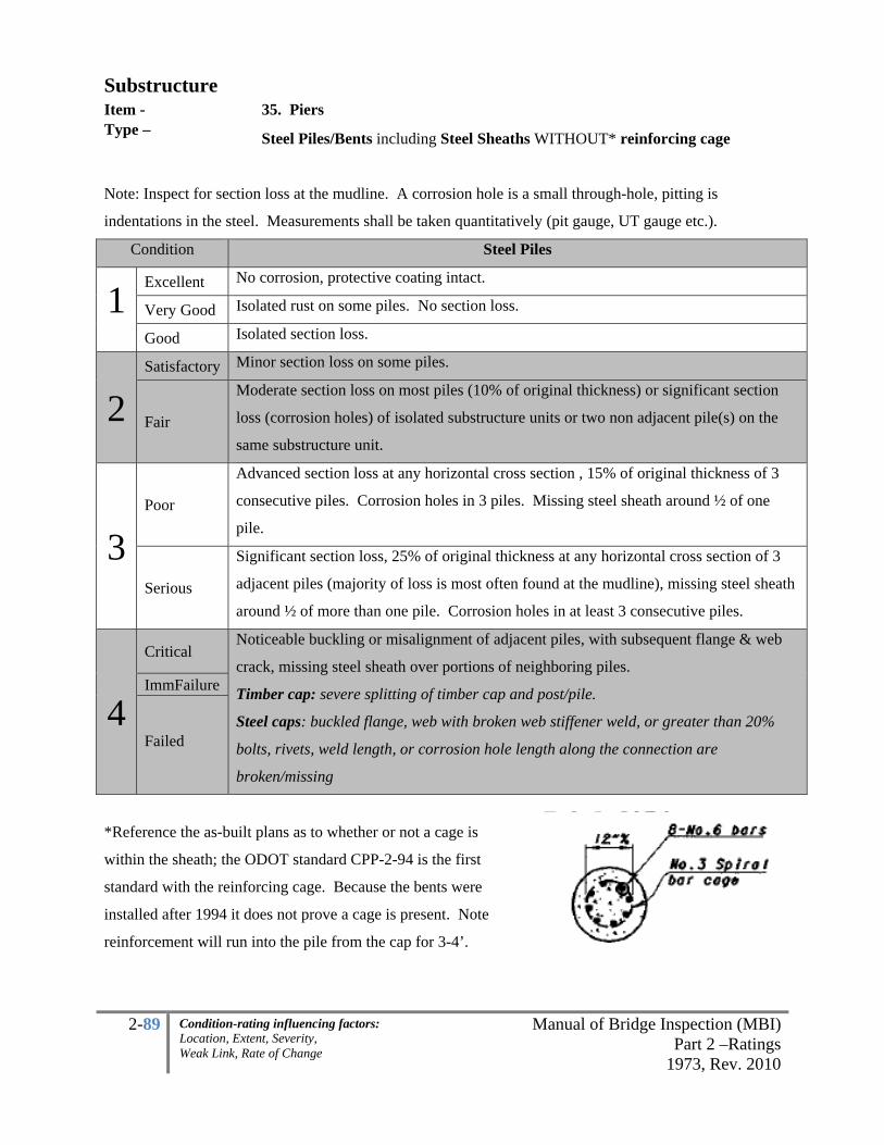
2-89 Manual of Bridge Inspection (MBI)Part 2 –Ratings
1973, Rev. 2010
Condition-rating influencing factors: Location, Extent, Severity, Weak Link, Rate of Change
Substructure Item - 35. Piers Type – Steel Piles/Bents including Steel Sheaths WITHOUT* reinforcing cage
Note: Inspect for section loss at the mudline. A corrosion hole is a small through-hole, pitting is
indentations in the steel. Measurements shall be taken quantitatively (pit gauge, UT gauge etc.).
Condition Steel Piles
1 Excellent No corrosion, protective coating intact.
Very Good Isolated rust on some piles. No section loss.
Good Isolated section loss.
2 Satisfactory Minor section loss on some piles.
Fair
Moderate section loss on most piles (10% of original thickness) or significant section
loss (corrosion holes) of isolated substructure units or two non adjacent pile(s) on the
same substructure unit.
3 Poor
Advanced section loss at any horizontal cross section , 15% of original thickness of 3
consecutive piles. Corrosion holes in 3 piles. Missing steel sheath around ½ of one
pile.
Serious
Significant section loss, 25% of original thickness at any horizontal cross section of 3
adjacent piles (majority of loss is most often found at the mudline), missing steel sheath
around ½ of more than one pile. Corrosion holes in at least 3 consecutive piles.
4
Critical Noticeable buckling or misalignment of adjacent piles, with subsequent flange & web
crack, missing steel sheath over portions of neighboring piles.
Timber cap: severe splitting of timber cap and post/pile.
Steel caps: buckled flange, web with broken web stiffener weld, or greater than 20%
bolts, rivets, weld length, or corrosion hole length along the connection are
broken/missing
ImmFailure
Failed
*Reference the as-built plans as to whether or not a cage is
within the sheath; the ODOT standard CPP-2-94 is the first
standard with the reinforcing cage. Because the bents were
installed after 1994 it does not prove a cage is present. Note
reinforcement will run into the pile from the cap for 3-4’.

2-90 Manual of Bridge Inspection (MBI)Part 2 –Ratings
1973, Rev. 2010
Condition-rating influencing factors: Location, Extent, Severity, Weak Link, Rate of Change
Substructure Item - 36. Pier Seats Type – All (predominant is reinforced concrete) The seats are the shelf or the horizontal face on which the bearings transfer load and the first 4-6” down
the vertical face or cap. Rate the deficiencies below the masonry plates of the bearings and above the top
4-6” of the pier within this item. Emphasis shall be given to those areas directly under the bearings and at
a 45 degree angle away from each bearing, and those areas with structural cracks extending through the
seats including flexure/shear cracks between beams (ex. negative moment cracks between beam-lines in
hammerhead piers). Slabs do not have pier seats.
• Redundant: Structures with more than 3 primary lines; there are more than three bearings
transferring the load path at each substructure unit per span.
• Nonredundant: Structures with 2 or 3 primary lines; there are two or three bearings transferring the
load path at each substructure unit per span.
Loss of Bearing Area Cracking
1 Excellent None No Cracks.
Very Good Minor spalling/delamination up to fascia bearings for redundant structure.
Hairline cracking, up to 1/16 wide with no rust staining, no dampness
Good Aesthetic deficiencies, minor spalling, delaminations. Minor loss under fascia bearings for redundant structure.
Hairline cracking, single crack greater than 1/16 without rust staining.
2
Satisfactory
Redundant: Spalling or delaminations up to masonry plate(s) but no undermining to interior beams. Minor undermining is possible under a fascia masonry plate. Nonredundant: Minor spalling, delaminations, no undermining.
Transverse cracks, some leaking. Hairline map cracking combined with mottled areas, cracks up to 1/8” wide with minor efflorescence or leakage.
Fair
Redundant: Fascia bearing loss up to 50%, interior bearings have spalling or delaminations under small portions of the masonry plates. Nonredundant: Spalling or delaminations up to masonry plate but no undermining.
Map cracking, structural cracks up to 1/8 inch wide with efflorescence and/or rust stain, leakage and mottled areas.
3 Poor
Redundant: One interior bearing loss up to 50%, at least two on one substructure unit up to 20% loss. Nonredundant: Spalling undermining portions of masonry plate.
Advanced cracking for example structural cracks wider than 1/8” wide with heavy leaking, efflorescence and staining.
Serious Redundant: At least two adjacent interior masonry plates on one substructure unit more than 20% loss. Nonredundant: Spalling undermining portions of masonry plate up to 20% of area.
4 Critical Any condition worse than above, crushing of steel cap under adjacent interior beams.
Redundant: Interior beams with loss up to 50%. Nonredundant: Spalling undermining portions of masonry plate more than 20% of area.
Imm/ Failure

2-91 Manual of Bridge Inspection (MBI)Part 2 –Ratings
1973, Rev. 2010
Condition-rating influencing factors: Location, Extent, Severity, Weak Link, Rate of Change
Substructure Item - 37. Backwall Type – All (predominant is reinforced concrete) The backwall is the portion of an abutment extending above the bridge seat which retains the approach
embankment. It may also serve as a support for an approach slab and/or anchorage for expansion joints.
Check backwalls for condition and amount of clearance between beam ends and face of backwall
which may indicate superstructure or substructure movement or pavement pressures. While
backwalls may cause serious problems, only in extreme conditions will the rating of the substructure be
reduced because of the backwalls. See item 33 for a description of the backwall/abutment delineation.
Condition Deterioration/Deficiencies
1 Excellent No deficiencies.
Very Good Minor deterioration. (ex. Hairline cracking)
Good Minor deterioration. (ex. Cracking)
2 Satisfactory
Moderate deterioration. (ex. Cracking, isolated discoloration, some beam-touching in
warmer temperatures)
Fair Moderate deterioration. (ex. Cracking, isolated discoloration, Backwall touching in
colder temperatures)
3 Poor
Advanced deficiencies. (ex. structural cracks with leakage from beams touching, 2 non
adjacent bays with heavy spalling)
Serious
Advanced deficiencies. (ex. structural cracks in more than one bay allowing moisture
infiltration, backwall sheared in 2 adjacent bays with heavy spalling and heavy steel
section loss)
4 Critical
1 bay allowing approach-fill onto seats. Multiple bays with heavy spalling and
infiltration. Backwall sheared and displaced due to beam contact.
ImmFailure Any worse than above. Failed

2-92 Manual of Bridge Inspection (MBI)Part 2 –Ratings
1973, Rev. 2010
Condition-rating influencing factors: Location, Extent, Severity, Weak Link, Rate of Change
Substructure Item - 38. Wingwalls Type – Concrete
Rating Spalling with Exposed
Reinforcement, Delaminations
Damp or Dark Areas (Saturation) Cracking and Rotation
% of area
1
Excellent No signs of distress, no discoloration
Very Good Minor delaminations, minor spalling
Minor discoloration
Isolated hairline cracking with no rust staining, no dampness, no leakage
Good Up to 1% Up to 5%
Minor problems, hairline cracking with isolated leaking, efflorescence. No rust staining. Map cracking combined with mottled areas up to 5%
2
Satisfactory
Up to 5% (unsound areas up to 10%) Minor isolated loss of concrete under arch fascia, bearing
Up to 10%
Minor structural cracking with leaking, efflorescence and rust staining. Minor differential settlement, Wingwall pulling away from bridge up to 1/2” gap
Fair
Up to 10%, (unsound areas up to 20%) Minor widespread loss of concrete under arch fascia, bearing
Up to 20%
Structural cracking with leaking, efflorescence and rust staining. Moderate settlement or rotation, Wingwall pulling away from bridge up to 1” gap or crack,
3 Poor
Advanced isolated loss of concrete under arch fascia, bearing. Combined total not exceeding 30% with more than 4 adjacent exposed reinforcing bars having greater than 10% section loss to the original diameter.
Advanced cracking with heavy leaking, efflorescence and rust staining. Severe differential settlement or rotation, Wingwall pulling away from bridge 2” per foot gap or crack,
Serious
Significant differential settlement, Wingwall pulling away from bridge up to 4” per foot gap or crack. Up to 30% spalling, delamination with more than 5 adjacent reinforcing bars have greater than 25% section loss to the original diameter OR Up to 50% damp/dark areas.
4
Critical
More than 30% spalling, delamination with more than 10 adjacent reinforcing bars having greater than 25% section loss to the original diameter OR More than 50% damp/dark areas; Extreme settlement, Wingwall pulling away from bridge more than 4” per foot gap or crack, active backfill movement through gap.
Imminent Failure
Major deterioration in critical structural components or obvious vertical or horizontal movement affecting structure stability. Bridge is closed to traffic but correction action may put back in light service
Failure Bridge closed, collapsed

2-93 Manual of Bridge Inspection (MBI)Part 2 –Ratings
1973, Rev. 2010
Condition-rating influencing factors: Location, Extent, Severity, Weak Link, Rate of Change
Substructure Item - 38. Wingwalls Type – Masonry
Condition Cracking Displacement/Settlement General
1
Excellent No signs of distress. Minor spalling of stone surface.
Very Good Minor spalling of stone surface. Scaling on of stone surface less than 1/2 inch.
Good Diagonal or vertical shear crack in isolated stones. Fracture of stone surface less than 2 inches.
2
Satisfactory Diagonal or vertical shear crack through several courses of stone.
Minor displacement, & minor differential settlement.
Wingwall pulling away from bridge up to 1/2” gap.
Fair Diagonal or vertical shear crack through several courses of stone.
Displacement may be bulge or leaning stones. Total displacement is less than 1/4 of stone depth. Moderate settlement or rotation.
Wingwall pulling away from bridge up to 1” gap or crack.
3 Poor
Settlement causing diagonal or vertical shear crack through several courses of stone with displacement.
Severe differential settlement or rotation. Total displacement is less than 1/3 of stone depth.
Wingwall pulling away from bridge up to 2” gap or crack. Large fractures or erosion of stone surfaces less than 5 inches on several adjacent stones.
Serious Large fractures or erosion of stone surfaces greater than 5 inches.
Several stones are displaced or missing. Significant differential settlement.
Large unsound areas. Misalignment of mortar joints. Wingwall pulling away from bridge up to 4” per foot gap or crack.
4 Critical
Tension cracks in asphalt due to wingwall settlement.
Numerous missing or displaced stones. Displacements greater than 1/3 of stone depth. Extreme settlement.
Wingwall pulling away from bridge more than 4” per foot gap.
ImmFailure Partially collapsed, lane closure.
Failed Total failure.

2-94 Manual of Bridge Inspection (MBI)Part 2 –Ratings
1973, Rev. 2010
Condition-rating influencing factors: Location, Extent, Severity, Weak Link, Rate of Change
Substructure Item - 38. Wingwalls Type –
MSE Walls
Condition Panels Joints Erosion Bowed
1
Excellent No Cracking or
Spalls. Uniform joint spacing.
Very Good
No Cracking or
Spalls, cracks may
exist in coping.
Minor variation in joint
spacing. None
Good Hairline cracking or
spalls.
Moderate variation in joint
spacing, minor sand in
joints.
Minor
2 Satisfactory
Cracks <1/4" on a
few panels.
Moderate sand in joints
but no exposed fabric nor
sand piles below joints.
Minor erosion
along panels, max
1’ deep.
Moderate
Fair
Cracks <1/4" many
panels, global,
minor spalling.
Exposed fabric at a few
isolated joints, small sand
pile.
Moderate erosion
along panels, max
2' deep.
Moderate
change since
as built.
3
Poor
Cracks >1/4",
global, moderate
spalling.
Exposed fabric at many
joints, sand pile(s) below
at least one joint, trees
growing between joints.
Erosion >2' deep
along panels.
Major
change since
as built.
Serious Spalling exposes
backfill.
Exposed fabric and active
sand piles below many
joints.
Erosion exposing
the top of the
leveling pad and
pad is not on rock,
exposed straps or
mesh.
Major,
changing,
global.
4 Critical
Any worse than
above.
Major leaking of sand
from joints.
Erosion
undermining
leveling pads.
Major,
changing,
systemic and
global.
ImmFailure Failed

2-95 Manual of Bridge Inspection (MBI)Part 2 –Ratings
1973, Rev. 2010
Condition-rating influencing factors: Location, Extent, Severity, Weak Link, Rate of Change
Substructure Item - 39. Fenders and Dolphins Type –
Any
Fenders and dolphins around piers or abutments protect the substructure against collision by vessels. They
are designed to absorb the energy of physical contact with the vessel. They are also used to deflect debris
and ice. Check for condition, damage and security of connection.
Condition General Description
1 Excellent
Very Good No problems noted.
Good Some minor problems.
2 Satisfactory Structural elements show some minor deterioration.
Fair All primary structural elements are sound but have minor section loss,
deterioration, spalling or scour.
3 Poor Advanced section loss, deterioration, spalling or scour.
Serious
Loss of section, deterioration, spalling or scour has seriously affected primary
structural components. Local failures are possible. Fatigue cracks in steel or
shear cracks in concrete may be present.
4 Critical
Advanced deterioration of primary structural elements. Fatigue cracks in steel or
shear cracks in concrete may be present or scour may have removed support.
ImmFailure Major deterioration or section loss present in critical structural components or
obvious vertical or horizontal movement affecting structure stability.
Failed Out of service - beyond corrective action.

2-96 Manual of Bridge Inspection (MBI)Part 2 –Ratings
1973, Rev. 2010
Condition-rating influencing factors: Location, Extent, Severity, Weak Link, Rate of Change
Substructure Item - 40. Scour Type –
Bridges over waterways
This item requires a two part code. The first box will indicate the type of inspection made:
1 Visual
2 Probing
3 Diving/Underwater
Visual inspection is not advisable for foundations in water not on piling or rock. An exception to this
would be a case where clear water is less than 1 foot deep and scour has not occurred in the past. Only
code the Diving code if the Team Leader signing the report played an active role in supervising or
participating in the actual underwater inspection. It is recommended that a Team Leader representing
the bridge owner is on sight in order to promote continuity from the previous underwater inspection.
Where the water level during low flow is deeper than 5-feet at any substructure unit an underwater
inspection is necessary. Update the inventory item #189 within every 60 months per the NBIS.
Update item #74 Scour Critical as appropriate. Bridge inspectors can bring down the scour critical rating
to a 4, 2, 1 or 0 based on field observations. A Scour POA (for Scour Critical Bridges – coded 3, 2, 1 or
0) template is available in the appendix and a Scour Critical Assessment Checklist guide is also available
in the appendix. This may be used and placed in the bridge file to help justify an assessment when
calculations are not used to adjust the Scour Critical item. When POA’s are complete update the survey
box 7in item 69.
Scour is the removal of material from the streambed or embankment as a result of the erosive action of
stream flow. Finding and monitoring and properly coding undermining and scour progression is of the
upmost concern. Lateral stream migration, restricted waterway openings or damaged hydraulic control
structures will be considered within the Channel condition rating. These can immediately affect the
stability of the substructure. For example, a debris field on the upstream nose of a pier restricts the
waterway and it also increases stream velocity at the pier and depth of the local scour.
In only extremely rare cases may scour be rated when the structure is not over a waterway but is
experiencing scour.

2-97 Manual of Bridge Inspection (MBI)Part 2 –Ratings
1973, Rev. 2010
Condition-rating influencing factors: Location, Extent, Severity, Weak Link, Rate of Change
Substructure Item - 40. Scour Type – Bridges over waterways
Inspectors must know if the structure inspected is on Spread Footing, or Deep Foundation as it can
greatly affect the condition ratings. Depending on whether the footing is on erodible soil, rock, erodible
shale or on piles will affect the
severity of the condition rating.
Scour can occur in stages
beginning with the exposure of the
top of the footing, then the vertical
face and then finally the
underside. Where the underside is
exposed this is called
undermining. It is very
important to record dimensions
of exposed footings (length,
height, depth, location) so the
next inspector will be able to
monitor change. Consideration shall be given to making a Cross Channel Profile (see appendix) to track
quantitative change.
Lastly inspect downstream for head cuts/knick-points that could move and influence the structure.

2-98 Manual of Bridge Inspection (MBI)Part 2 –Ratings
1973, Rev. 2010
Condition-rating influencing factors: Location, Extent, Severity, Weak Link, Rate of Change
Substructure Item - 40. Scour Type –
Spread Footing on Soil OR Unknown Foundations
Condition Description*
1 Excellent No Problems noted. Very Good Minor scour holes developing, scour protection placed.
Good
Some minor problems. Minor scour holes exist, top of footing exposed, probing indicated soft material in scour hole.
2 Satisfactory
Damage to scour countermeasures, probing indicates soft material in scour hole. Sides of footings exposed less than 6 inches.
Fair
Minor scour, damage to scour countermeasures, probing indicates soft material in scour hole. Unprotected footings along the vertical sides are exposed less than 12-inches high, corner of footing may have minor undermining.
3 Poor
Advanced scour. Unprotected vertical side of footing exposed, full height, less than 1/3 the length.
Serious Scour has seriously affected the primary structural components Local failures are possible. Minor undermining exposing the underside less than 1/3 the length.
4 Critical
Scour may have removed substructure support. Local failures are possible. Any substructure unit with more than 20% of bearing capacity removed. Underside of footing exposed more than 1/3 the length.
Imminent Failure
Obvious vertical or horizontal movement due to scour that is affecting the structure stability. Bridge is closed to traffic but corrective action may put bridge back in to light service.
Failed Out of service - beyond corrective action.
*Condition shall be adjusted based on the rate of change since the as-built condition. This item may be
rated higher, for example, if the as-built condition had the top face of the spread footing exposed and it
has not changed. Also, due to the dynamic nature of the waterway the ratings may be coded lower if a
dramatic change occurred since the previous inspection. Unknown foundations on soil shall be rated the
same as a spread footing on soil. Those spread footings on rock shall be rated as deep foundations.

2-99 Manual of Bridge Inspection (MBI)Part 2 –Ratings
1973, Rev. 2010
Condition-rating influencing factors: Location, Extent, Severity, Weak Link, Rate of Change
Substructure Item - 40. Scour
Type – Deep Foundations: Piles, Drilled Shafts, including Spread Footing on Rock
Condition Description*
1 Excellent No Problems noted. Very Good Minor scour holes developing, scour protection placed.
Good
Some minor problems. Minor scour holes exist, top of footing exposed, properly designed countermeasures restore the condition, probing indicated soft material in scour hole. Footings exposed less than 6 inches.
2 Satisfactory Damage to scour countermeasures, probing indicates soft material in scour hole.
Fair Minor scour, damage to scour countermeasures, probing indicates soft material in scour hole. Full height side of footing exposed.
3 Poor
Advanced scour. Underside of footing and piling exposed more than 1/3 the length, spread footing on rock the edge of footing may be exposed less than 1/3 the length.
Serious
Scour has seriously affected the primary structural components Local failures are possible. Undermining with 1 piling exposed more than 5-foot-deep less than 1/3 the length, spread footing on rock the edge of footing undermined less than 1/3 the length.
4 Critical
Scour may have removed substructure support. Local failures are possible. Any substructure unit with more than 20% of bearing capacity removed. Underside of footing exposed with any 1 piling exposed more than 5-foot deep, or piling exposed less than 5-foot deep more than 1/3 the length, spread footing on rock with undermining up to 1/3 the length.
Imminent Failure
Obvious vertical or horizontal movement due to scour that is affecting the structure stability. Bridge is closed to traffic but corrective action may put bridge back in to light service.
Failed Out of service - beyond corrective action. *Condition shall be adjusted based on the rate of change since the as-built condition. This item may be
rated higher, for example, if the as-built condition had the top face of the spread footing exposed and it
has not changed. Also, due to the dynamic nature of the waterway the ratings may be coded lower if a
dramatic change occurred since the previous inspection. Unknown foundations on soil shall be rated the
same as a spread footing on soil. Those spread footings on rock shall be rated as deep foundations.

2-100 Manual of Bridge Inspection (MBI)Part 2 –Ratings
1973, Rev. 2010
Condition-rating influencing factors: Location, Extent, Severity, Weak Link, Rate of Change
Substructure Item - 41. Slope Protection Type – General
The protection will retain the slope around the abutments and substructure units (where slopes exist) in
order to protect the structure from undermining. Examine areas directly under the bridge for erosion,
missing stone, broken concrete, etc. If channel extends all the way to the abutments, there is no slope
protection to rate. Where MSE walls exist and the substructure is on piles then rate the MSE wall as
slope protection. Often the previous abutment will serve as the current slope protection. In this instance
rate the abutment as to how well it is protecting the slope.
Condition Erosion Protection Condition
1 Excellent Very Good No deficiencies. No deficiencies.
Good
Minor Erosion not affecting
substructure unit(s), beginning to
slump.
Minor deficiencies, minor repairs
recommended.
2 Satisfactory
Minor erosion damage (ie. wingwall
or secondary substructure unit(s)),
protection is cracked.
Minor deficiencies, sloughing or sliding
of protection however still functioning
as designed.
Fair Small erosion channels/failure, up to
6" deep, erosion ruts exist.
Moderate deficiencies, sloughing or
sliding of protection however still
functioning as designed.
3 Poor
Significant erosion, up to 2' deep,
erosion ruts.
Moderate and active slope protection
failure. Slight Undermining, No longer
stabilizing the slope, collapsing rip rap.
Serious
Major erosion, up to 2' deep, erosion
channels exposing foundation
underside
Major and active removal of slope
protection, undermining.
4 Critical
Major erosion , greater than 2'
deep/wide ruts that are directly
affecting substructure units, example
5’ of one piling is exposed.
Serious undermining, protection is
actively moving and no longer
stabilizing the slope.
Imm Failure Any Worse than above. Failed

2-101 Manual of Bridge Inspection (MBI)Part 2 –Ratings
1973, Rev. 2010
Condition-rating influencing factors: Location, Extent, Severity, Weak Link, Rate of Change
Substructure Item - 41. Slope Protection Type – MSE Walls
Condition Panels Joints Erosion Bowed
1
Excellent No Cracking or
Spalls Uniform joint spacing
Very Good
No Cracking or
Spalls, cracks may
exist in coping
minor variation in joint
spacing None
Good Hairline cracking or
spalls
Moderate variation in joint
spacing, minor sand in
joints
Minor
2 Satisfactory
Cracks <1/4" on a
few panels
Moderate sand in joints but
no exposed fabric nor sand
piles below joints
Minor erosion
along panels, max
1’ deep
Minor
Fair
Cracks <1/4" many
panels, global, minor
spalling
Exposed fabric at a few
isolated joints
Moderate erosion
along panels, max
2' deep
Moderate
3
Poor Cracks >1/4", global,
moderate spalling
Exposed fabric at many
joints, sand pile(s) below at
least one joint, trees
growing between joints
Erosion >2' deep
along panels Major
Serious Spalling exposes
backfill
Exposed fabric and sand
piles below many joints
Erosion exposing
the top of the
leveling pad and
pad is not on rock,
exposed straps or
mesh
Major, global
4 Critical
Any worse than
above
Major leaking of sand from
joints
erosion
undermining
leveling pads
Major,
systemic and
global
ImmFailure Failed

2-102 Manual of Bridge Inspection (MBI)Part 2 –Ratings
1973, Rev. 2010
Condition-rating influencing factors: Location, Extent, Severity, Weak Link, Rate of Change
Substructure Item - 42. SUMMARY Type –
All
All Grayed Boxes are NOT 1-4 Ratings (Summary item is 9-0, scour inspection type is 1, 2 or 3).
SUBSTRUCTURE
33. Abutments 34. Abutment Seats 35. Piers 36. Pier Seats 37. Backwalls 38. Wingwalls 39. Fenders and Dolphins 40. Scour (Insp Type – 1, 2, 3)
41. Slope Protection 42. SUMMARY
Item 37. Backwalls and Item 41 Slope Protection (MSE Walls) may control the summary in extreme
circumstances usually on up to 1% of the inventory. 1-4 Individual Items % are based on the WORST
SPAN while the 9-0 Summary Items % are based on the item throughout the TOTAL BRIDGE.
1-4 INDIVIDUAL 9-0 SUMMARY
1 9-Excellent
8-Very Good
7-Good
2 6-Satisfactory
5-Fair
3 4-Poor
3-Serious
4 2-Critical
1-Imminent Failure
0-Failed

2-103 Manual of Bridge Inspection (MBI)Part 2 –Ratings
1973, Rev. 2010
Condition-rating influencing factors: Location, Extent, Severity, Weak Link, Rate of Change
CULVERTS
Culverts shall be inspected for:
1. Deterioration to barrel material or footing
2. Cracks
3. Dents and Localized Damage
If the culvert has been extended, code the worst condition of the most predominant material under the
traveled lanes.
Deterioration –Corrosion and abrasion are the most common ways in which culverts degrade. Corrosion
is the deterioration of metal due to electrochemical or chemical reactions. Culverts are subject to
corrosion in certain aggressive environments.
Abrasion is the wearing away of culvert materials by the erosive action of bedload carried in the stream.
Abrasion is generally most serious in steep areas where high flow rates carry sand and rocks that wear
away the culvert invert. Abrasion can also accelerate corrosion by wearing away protective coatings.
Corrosion and abrasion of culverts can be a serious problem with adverse effects on structural
performance. Damage due to corrosion and abrasion is a common cause for culvert replacement. The
condition of the metal in corrugated metal culverts and any coatings, if used, should be considered when
assigning a rating to the culvert barrel.
The inspection should include visual observations of metal corrosion and abrasion. As steel corrodes it
expands considerably. Relatively shallow corrosion can produce thick deposits of scale. A geologist's
pick-hammer can be used to scrape off heavy deposits of rust and scale permitting better observation of
the metal. A hammer can also be used to locate unsound areas of exterior corrosion by striking the culvert
wall with the pick end of the hammer. When severe corrosion is present, the pick will deform the wall or
break through it. Protective coatings should be examined for abrasion damage, tearing, cracking, and
removal. The inspector should document the extent and location of surface deterioration problems.

2-104 Manual of Bridge Inspection (MBI)Part 2 –Ratings
1973, Rev. 2010
Condition-rating influencing factors: Location, Extent, Severity, Weak Link, Rate of Change
Concrete inverts are usually floating slabs used to carry water. Invert slabs provide protection against
erosion and undermining, and are also used to improve hydraulic efficiency. Concrete inverts are
sometimes used in circular, as well as other culvert shapes, to protect the metal from severe abrasive or
severe corrosive action. Concrete invert slabs should be checked for undermining and damage such as
spalls, open cracks, and missing portions. The significance of damage will depend upon its effect on the
underlying material.
Metal structures may have a concrete pedestal with concrete footings. The concrete material shall be
evaluated using the rating scale for abutments and the worst case shall govern the rating. The governing
type shall be noted on the inspection form. Longitudinal settlement affects shall be rated under alignment
and transverse movements shall be rated under the shape factor.
Deterioration may occur in concrete and masonry footings that is not related to settlement but is caused
by the concrete or mortar. In arches with no invert slab, the inspector should check for erosion and
undermining of the footings and look for any indication of rotation of the footing.
Cracks – Cracking may occur in most culvert materials and can indicate overloading resulting in small
(localized) failures in shear, flexure, or simply damage during installation.
In metal structures, cracking may occur along bolt holes of longitudinal seams and can be serious if
allowed to progress. These cracks are most serious when accompanied by significant deflection,
distortion, and other conditions indicative of backfill or soil problems. Metal culverts with in-line seams
are NOT considered “fracture critical” per the NBIS.
In concrete structures, reinforcing steel is designed to assume some of the imposed loads. Therefore,
small hairline cracks (widths less than 1/8 inch) are expected and are not cause for alarm. The location of
cracking in concrete structures can indicate the type of problems being experienced. In concrete pipe,
longitudinal cracks at the 3, 6, 9, and 12 o’clock positions indicate flexure cracking caused by poor side
support. Longitudinal cracking in the invert at the 5 and 7 o’clock positions indicate shear cracking
caused by poor haunch support. Likewise, cracking at the 11 and 1 o’clock positions may be the result of
shear forces from above the structure. Transverse cracks may also occur and are usually the result of
non-uniform bedding or fill material causing point loads on the pipe.

2-105 Manual of Bridge Inspection (MBI)Part 2 –Ratings
1973, Rev. 2010
Condition-rating influencing factors: Location, Extent, Severity, Weak Link, Rate of Change
Plastic pipe materials may experience splits. A split (rip, tear, or crack) is any separation in the wall
material other than at a designed joint.
For all culvert materials, any amount of cracking should be recorded and the appropriate rating assigned
from the rating condition tables.
Dents and Localized Damage - All culverts should be inspected for localized damage caused by
construction procedures or from maintenance forces. For flexible pipe, wall damage such as dents,
bulges, creases, cracks, and tears can be serious if the defects are extensive and can impair either the
integrity of the barrel in ring compression or permit infiltration of backfill. Small, localized examples are
not ordinarily critical. When the deformation type damages are critical, they will usually result in a
misshaped cross section.
The inspector should document the type, extent, and location of all significant wall damage defects. When
examining dents in corrugated steel culverts, the opposite side of the plate should be checked, if possible,
for cracking or debonding of the protective coating.
NOTE: The condition of the ends of the culvert shall not govern the condition rating.
CULVERT 43. General 44. Alignment 45. Shape 46. Seams 47. Headwall or Endwalls 48. Scour (inspection type 1, 2, 3) 49. Abutments 50. SUMMARY
Select the lowest of the bold black box items when coding the Summary item. Item 47. Headwall,
Endwalls may control in less frequent situations where losing them would result in direct loss of a traffic
lane(s). 1-4 Individual Items % are based on the WORST SPAN while the 9-0 Summary Items % are
based on the item throughout the TOTAL BRIDGE or all spans (for multi-barrel/cell culverts).

2-106 Manual of Bridge Inspection (MBI)Part 2 –Ratings
1973, Rev. 2010
Condition-rating influencing factors: Location, Extent, Severity, Weak Link, Rate of Change
Culverts Item - 43. General Type –
Corrugated Metal Culvert (CMP)
Condition Surface Condition Perforations/Holes
1 Excellent New condition; galvanizing intact; no corrosion.
Very Good Discoloration of surface; galvanizing partially gone along invert but no layers of rust.
Good Discoloration of surface, Galvanizing gone along invert but no layers of rust. Superficial corrosion but no pitting.
May have minor corrosion holes (with an area less than 3 square inches per square foot) in pipe material located at ends of pipe (length not to exceed 4 feet and not located beneath roadway).
2 Satisfactory
Galvanizing gone along invert with layers of rust. Moderate pitting; sporadic pitting of invert.
Minor corrosion holes (with an area less than 6 square inches per square foot, 4%) in pipe material located at ends of pipe (length not to exceed 4 feet and not located beneath roadway).
Fair Heavy rust and scale. Deep pitting. Section loss and perforations and ends.
Corrosion holes (with an area less than 15 square inches per square foot, 10%) throughout pipe material. Holes in metal at end in invert and not located under roadway.
3 Poor
Extensive heavy rust; thick and scaling rust throughout pipe; deep pitting. Overall thin metal, which allows for an easy puncture with chipping hammer.
Perforations throughout invert (with an area less than 30 square inches per square foot, 20% of structure affected).
Serious
Extensive heavy rust; thick and scaling rust throughout pipe; deep pitting. Overall thin metal, which allows for an easy puncture with chipping hammer. End section corroded away.
Scattered perforations throughout invert (with an area less than 36 square inches per square foot, 25%).
4 Critical Perforations throughout invert (with an area greater than 36 square inches per
square foot, 25%). Corrective action required to maintain traffic.
Imm Failure Pipe partially collapsed. Corrective action may put back in light service.
Failed Total failure of pipe. Replacement is necessary.

2-107 Manual of Bridge Inspection (MBI)Part 2 –Ratings
1973, Rev. 2010
Condition-rating influencing factors: Location, Extent, Severity, Weak Link, Rate of Change
Culverts Item - 43. General Type – Concrete
Rating Spalling with Exposed
Reinforcement
Damp or Dark Areas
(Saturation) Cracking
% of area
1
Excellent No signs of distress, no discoloration
Very Good Minor delaminations, minor spalling
Minor discoloration
Isolated hairline cracking with no rust staining, no dampness, no leakage
Good Up to 1% Up to 5%
Minor problems, hairline cracking with isolated leaking, efflorescence. No rust staining. Map cracking combined with mottled areas up to 5%
2 Satisfactory
Up to 5% (unsound areas up to 10%)
Up to 10%
Minor structural cracking with leaking, efflorescence and rust staining. Map cracking combined with mottled areas up to 10%. Minor settlement.
Fair Up to 10 (unsound areas up to 20%)
Up to 20%
Structural cracking with leaking, efflorescence and rust staining. Map cracking combined with mottled areas up to 20%. Moderate rotation or settlement
3 Poor
Combined total not exceeding 30% with more than 4 adjacent exposed reinforcing bars having greater than 10% section loss to the original diameter.
Advanced cracking with heavy leaking, efflorescence and rust staining. Hairline map cracking combined with mottled areas up to 30%. Severe settlement.
Serious Up to 30% spalling, delamination with more than 5 adjacent reinforcing bars have greater than 25% section loss to the original diameter OR Up to 50% damp/dark areas, significant differential settlement (up to 2” vertical, or up to 4” horizontal)
4
Critical
More than 30% spalling, delamination with more than 10 adjacent reinforcing bars having greater than 25% section loss to the original diameter OR More than 50% damp/dark areas;. Extreme settlement (greater than 2” vertical or greater than 10% of the height; horizontal movement up to 4” max).
Imminent Failure
Major deterioration in critical structural components or obvious vertical or horizontal movement affecting structure stability. Bridge is closed to traffic but correction action may put back in light service.
Failure Bridge closed, collapsed
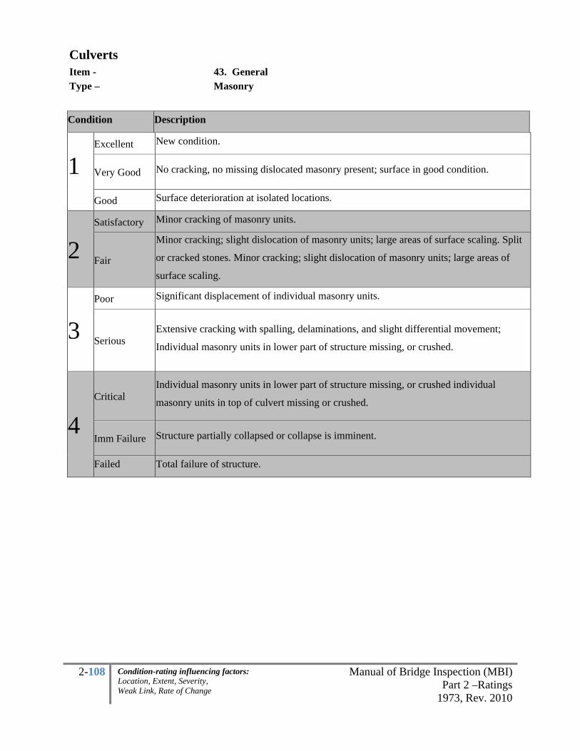
2-108 Manual of Bridge Inspection (MBI)Part 2 –Ratings
1973, Rev. 2010
Condition-rating influencing factors: Location, Extent, Severity, Weak Link, Rate of Change
Culverts Item - 43. General Type – Masonry
Condition Description
1 Excellent New condition.
Very Good No cracking, no missing dislocated masonry present; surface in good condition.
Good Surface deterioration at isolated locations.
2 Satisfactory Minor cracking of masonry units.
Fair
Minor cracking; slight dislocation of masonry units; large areas of surface scaling. Split
or cracked stones. Minor cracking; slight dislocation of masonry units; large areas of
surface scaling.
3 Poor Significant displacement of individual masonry units.
Serious Extensive cracking with spalling, delaminations, and slight differential movement;
Individual masonry units in lower part of structure missing, or crushed.
4 Critical
Individual masonry units in lower part of structure missing, or crushed individual
masonry units in top of culvert missing or crushed.
Imm Failure Structure partially collapsed or collapse is imminent.
Failed Total failure of structure.

2-109 Manual of Bridge Inspection (MBI)Part 2 –Ratings
1973, Rev. 2010
Condition-rating influencing factors: Location, Extent, Severity, Weak Link, Rate of Change
Culverts Item - 44. Alignment Type – All
Culverts not on Footings: Used for the rating of precast segments, corrugated metal pipe that has been
coupled or banded together. The alignment rating for the culvert is to account for longitudinal
irregularities in the barrel. The culvert barrel is to be inspected for discontinuities and settlement between
adjacent culvert segments.
Culverts on Footings: Concrete footing defects such as settlement can be used in structural plate arches,
long-span arches, and box culverts. Metal footings are occasionally used for the arch and box culvert
shapes. The “superstructure” depends on the footing to transmit the vertical load into the foundation. A
metal plate arch is usually bolted in a base channel and is secured in the footing. Precast units are grouted
into a key way of the footing. Cast-in-place units may be poured continuous. Settlement may show up as
severe cracking, spalling, or crushing across the footing at the critical spot, however, there may be
deterioration of the concrete or masonry footings that is not related to settlement.
Definitions:
• Differential settlement – One section of the footing settles more than the rest of the footing.
• Rotational settlement- The footing starts to tip in either direction due to lateral forces or
undermining.
• Uniform settlement- The whole footing settles and will not ordinarily affect flexible culverts.
Culvert alignment for Masonry culverts shall be rated for continuity between adjacent stones.

2-110 Manual of Bridge Inspection (MBI)Part 2 –Ratings
1973, Rev. 2010
Condition-rating influencing factors: Location, Extent, Severity, Weak Link, Rate of Change
Culverts Item - 44. Alignment Type – Precast segments, Corrugated Pipe
Condition Description
1 Excellent Straight line between sections.
Very Good Minor settlement or misalignment.
Good Minor misalignment at joints; off sets less than 1/2 inch no fill settlement. Minor
settlement or misalignment, ponding less than 3 inches.
2 Satisfactory
Fair, minor misalignment and settlement at isolated locations. Moderate settlement or
misalignment, ponding between 3 and 5 inches.
Fair
Minor misalignment or settlement throughout culvert. Ponding (depths less than 5 inches)
of water due to sagging or misalignment of pipe sections, end sections dislocated and
about to drop off. Four or more sections with offset less than 3 inches.
3
Poor
Considerable settlement and misalignment of pipe. Significant ponding (depths less than 6
inches) of water due to sagging or misalignment of pipes sections, end sections dislocated
about to drop off. Four or more sections with offset less than 4 inches. Rotation of
foundation.
Serious
Any condition described in “Poor” but is excessive in scope. Severe movement or
differential settlement of the segments or loss of fill. Metal culverts have extreme
distortion and deflection in one section. Significant ponding (depths greater than 6
inches) of water due to sagging or misalignment of pipes sections, end-section drop-off
has occurred. Four or more sections with off sets greater than 4 inches.
4 Critical
Culvert not functioning due to alignment problems throughout. Metal culverts have
extreme distortion and deflection throughout.
ImmFailure Culvert partially collapsed or collapse is imminent.
Failed Culvert collapsed.

2-111 Manual of Bridge Inspection (MBI)Part 2 –Ratings
1973, Rev. 2010
Condition-rating influencing factors: Location, Extent, Severity, Weak Link, Rate of Change
Culverts Item - 44. Alignment Type – Masonry
Condition Description
1 Excellent New Condition.
Very Good Straight lines between masonry units.
Good Generally good; minor misalignment at joints.
2 Satisfactory Fair, minor misalignment or settlement.
Fair Generally fair; minor misalignment or settlement.
3 Poor Considerable settlement or misalignment.
Serious
Any condition described in “Poor” but is excessive in scope. Severe movement or
differential settlement of the segments, or loss of fill. Significant ponding of water due
to sagging or misaligned masonry units; end section drop off has occurred.
4 Critical
Critical; culvert not functioning due to severe misalignment. Severe settlement of
roadway due to loss of fill.
Imminent Failure
Structure partially collapsed or collapse is imminent.
Failed Structure collapsed.

2-112 Manual of Bridge Inspection (MBI)Part 2 –Ratings
1973, Rev. 2010
Condition-rating influencing factors: Location, Extent, Severity, Weak Link, Rate of Change
Culverts Item - 45. Shape Type – Flexible Culverts Only
The barrel of the culvert shall be inspected for evidence of flattening, buckling, bulging, out-of-roundness
and other signs that the shape is not equal to original design. The Shape rating should be used for flexible
culvert structures and left blank for rigid culverts. Rigid structures do not deflect appreciably before
cracking or fracturing and therefore shape inspections are of little value. Defects in the culvert barrel for
rigid structures will be rated under other items.
The shape inspection should begin by approaching the culvert from the ends and sighting the sides and
top. Also check for signs of pavement depression, guardrail movement, or gaps between headwalls and
the pipe barrel. An important feature to observe and measure when inspecting flexible culverts is the
cross-sectional shape of the culvert barrel. The shape rating for the culvert is to account for irregularities
transverse to culvert barrel.
Dimensional checks should be made for suspect structures and these dimensions should be monitored
over time. If there is instability of the backfill, the pipe will continue to change shape. A critical area for
the inspection of long span metal culverts is at the 2 o’clock and 10 o’clock locations. An inward bulge at
these locations may indicate potential failure of the structure.
When distortion or curve flattening is apparent, the extent of the flattened area, in terms of arc length,
length of culvert affected, and the location of the flattened area should be described in the inspection
report. The length of the chord across the flattened area and the middle ordinate of the chord should be
measured and recorded. The chord and middle ordinate measurements can be used to calculate the
curvature of the flattened area using the formula shown in the appendix.
For structures with shallow cover, the inspector shall make observations of the culvert with a few live
loads passing over it. Discernible movement in the structure may indicate possible instability and a need
for more in-depth investigation.
The number of measurement locations depends upon the size and condition of the structure. Long-span
culverts should normally be measured at the end and at 25-foot intervals. Measurements may be required
at more frequent intervals if significant shape changes are observed. The smaller pipe culverts can usually

2-113 Manual of Bridge Inspection (MBI)Part 2 –Ratings
1973, Rev. 2010
Condition-rating influencing factors: Location, Extent, Severity, Weak Link, Rate of Change
Culverts Item - 45. Shape Type – Flexible Culverts Only
be measured at longer intervals than long-span culverts. Metering programs might be needed to determine
the rate of movement.
Arches
Arches are fixed on concrete footings, usually below or at the spring line. The spring line is a line
connecting the outermost points on the sides of a culvert. This difference between pipes and arches means
that an arch tends to deflect differently during the placement of backfill. Backfill forces tend to flatten the
arch sides and peak its top because the spring line cannot move inward like the wall of a round pipe. As a
result, important shape factors to look for in an arch are flattened sides, peaked crown, and a flattened top
arc.
Another important shape factor in arches is symmetry. If the arch was erected with the base channels not
square to the centerline, it can cause a racking of the cross section. A racked cross-section is one that is
not symmetrical about the centerline of the culvert. One side tends to flatten; the other side tends to curve
more while the crown moves laterally and possibly upward. If these distortions are not corrected before
backfilling the arch, they usually get worse as backfill is placed.
Arches in fair to good condition will have the following characteristics: a good shape appearance with
smooth and symmetrical curvature, and a rise within three to four percent of design. Marginal condition
would be indicated when the arch is significantly non-symmetrical, when arch height is five to seven
percent less or greater than design, or when side or top plate flattening has occurred such that the plate
radius is 50 to 100 percent greater than design. Arches in poor to critical condition will have a poor shape
appearance including significant distortion and deflection, extremely non-symmetrical shape, severe
flattening (radius more than 100 percent greater than design) of the sides or top plates, or a rise more than
eight percent greater or less than the designed rise. Guidelines for measurements are given in the
appendix.

2-114 Manual of Bridge Inspection (MBI)Part 2 –Ratings
1973, Rev. 2010
Condition-rating influencing factors: Location, Extent, Severity, Weak Link, Rate of Change
Culverts Item - 45. Shape Type – Flexible Culverts Only
Corrugated Metal Box Culverts
The key shape factor in a box culvert is the top arc. The design geometry is clearly very “flat” to begin
with and therefore does not allow much room for deflection. The span at the top is also important and can
only tolerate very minor increases.
The side plates often deflect slightly inward or outward. Generally an inward deflection would be the
more critical as an outward movement would be restrained by soil.
Shape factors to be checked visually include flattening of top arc, outward movement of sides, or inward
deflection of the sides. The inspector should note the visual appearance of the shape and should measure
and record the rise and the horizontal span at the top of the straight legs. If the rise is more or less than 1
½ percent of the design rise, the curvature of the large top radius should be checked. Guidelines for
measurements are given in the appendix.

2-115 Manual of Bridge Inspection (MBI)Part 2 –Ratings
1973, Rev. 2010
Condition-rating influencing factors: Location, Extent, Severity, Weak Link, Rate of Change
Culverts Item - 45. Shape Type – Flexible Culverts Only
Condition Description % Change of Cross Section*
1 Excellent
New Condition. May exhibit minor
damage along edge of inlet or outlet
due to construction
Very Good Smooth curvature in barrel span dimension within 1 percent of design.
Good Top half of pipe smooth but minor
flattening of bottom span dimension within 2.5 percent of design.
2
Satisfactory Smooth curvature in top half, bottom
flat span dimension up to 5 percent greater than design.
Fair
Generally fair, significant distortion in
top in one location; bottom has slight
reverse curvature in one location but
generally fair
span dimension up to 10 percent greater than
design. Non-symmetric shape.
3
Poor
Marginal significant distortion
throughout length of pipe, lower third
may be kinked
span dimension up to 15 percent greater than
design, noticeable dip in guardrail over pipe.
Serious
Poor, extreme deflection at isolated
locations, flattening at top of arch or
crown; bottom has reverse curvature
throughout;
span dimension more than 15 percent greater than
design. Extreme non-symmetric shape.
4 Critical
Critical, extreme distortion and
deflection throughout pipe
span dimension more than 20 percent greater than
design.
ImmFailure Structure partially collapsed with
crown in reverse curve.
Failed Structure collapsed.
* Refer to the Appendix for further detail in taking measurements of corrugated metal culverts.

2-116 Manual of Bridge Inspection (MBI)Part 2 –Ratings
1973, Rev. 2010
Condition-rating influencing factors: Location, Extent, Severity, Weak Link, Rate of Change
Culverts Item - 46. Seams Type – All
Key factors to look for in the inspection of seams and joints are indications of backfill infiltration and
water exfiltration. Excessive seepage through an open joint can cause soil infiltration or erosion of the
surrounding backfill material reducing lateral support. Inspection will require a flashlight. Open joints
may be probed with a small rod or flat rule to check for voids. Joint defects shall be recorded.
Joint defects include:
1. Open joints
2. Seepage at the joints
3. Surface sinkholes over the culvert
Seepage along the outside of the culvert barrel may remove supporting material. This process is referred
to as “piping”, since a hollow cavity similar to a pipe is often formed. Piping can also occur through open
joints. Piping is controlled by reducing the amount and velocity of water seeping along the outside of the
culvert barrel. This may require watertight joints and in some cases anti-seep collars. Good backfill
material and adequate compaction of that material are also important.
Corrugated Metal Multi-plate Structures
Seams are rated for corrugated metal, multiplate structures. All bolted splice seams should be checked for
loose, missing or severely corroded bolts, cusping at overlap, and tears or cracks in metal at the bolt lines.
Circumferential Seams - The circumferential seams in helical pipe, like joints in factory pipe, do not carry
ring compression thrust in the pipe. They do make the conduit one continuous structure. Distress in these
seams is rare and will ordinarily be the result of a severe differential deflection or distortion problem or
some other manifestation of soil failure. For example, a steep sloping structure through an embankment
may be pulled apart longitudinally if the embankment moves down. Plates should be installed with the
upstream plate overlapping the downstream plate to provide a “shingle” effect in the circumferential
seam. Seam distress is important to note during inspections since it would indicate a basic problem of
stability in the fill. Circumferential seam distress can also be a result of foundation failure, but in such
cases should be clearly evident by the vertical alignment.

2-117 Manual of Bridge Inspection (MBI)Part 2 –Ratings
1973, Rev. 2010
Condition-rating influencing factors: Location, Extent, Severity, Weak Link, Rate of Change
Culverts Item - 46. Seams Type – All
Longitudinal Seam Defects in Structural Plate Culverts - Longitudinal seams should be visually inspected
for open seams, cracking at bolt holes, plate distortion around the bolts, bolt tipping, cocked seams,
cusped seams, and for significant metal loss in the fasteners due to corrosion. In riveted or spot welded
pipes, the seams are longitudinal and carry the full ring compression in the pipe. These seams, then, must
be sound and capable of handling high compression forces. When inspecting the longitudinal seams of
bituminous-coated corrugated metal culverts, cracking in the bituminous coating may indicate seam
separation.
Seam Defects in Structural Plate Culverts:
(1) Loose Fasteners - Seams should be checked for loose or missing fasteners. For steel
structures the longitudinal seams are bolted together with high-strength bolts in two rows; one
row in the crests and one row in the valleys of the corrugations. These are bearing type
connections and are not dependent on a minimum clamping force of bolt tension to develop
interface friction between the plates. Fasteners in steel structural plate may be checked for
tightness by tapping lightly with a hammer and checking for movement.
For aluminum structural plate, the longitudinal seams are bolted together with normal
strength bolts in two rows with bolts in the crests and valleys of both rows. These seams
function as bearing connections, utilizing bearing of the bolts on the edges of holes and
friction between the plates.
(2) Cocked and Cusped Seams - The longitudinal seams of structural plate are the principal
difference from factory pipe. The shape and curvature of the structure is affected by the
lapped bolted longitudinal seam. Improper erection or fabrication can result in cocked seams
or cusped effects in the structure at the seam. Slight cases of these conditions are fairly
common and frequently not significant. However, severe cases can result in failure of the
seam or structure. When a cusped seam is significant the structure's shape appearance and
key dimensions will differ significantly from the design shape and dimensions. The cusp
effect should cause the structure to receive very low ratings on the shape inspection if it is a

2-118 Manual of Bridge Inspection (MBI)Part 2 –Ratings
1973, Rev. 2010
Condition-rating influencing factors: Location, Extent, Severity, Weak Link, Rate of Change
Culverts Item - 46. Seams Type – All
serious problem. A cocked seam can result in loss of backfill and may reduce the ultimate
ring compression strength of the seam.
(3) Seam Cracking - Cracking along the bolt-holes of longitudinal seams can be serious if
allowed to progress. As cracking progresses, the plate may be completely severed and the
ring compression capability of the seam lost. This could result in deformation or possible
failure of the structure. Longitudinal cracks are most serious when accompanied by
significant deflection, distortion, and other conditions indicative of backfill or soil problems.
Longitudinal cracks are caused by excessive bending strain, usually the result of deflection.
Cracking may occasionally be caused by improper erection practices such as using bolting
force to “lay down” a badly cocked seam.
(4) Bolt Tipping - The bolted seams in structural plate culverts only develop their ultimate
strength under compression. Bolt tipping occurs when the plates slip. As the plates begin to
slip, the bolts tip, and the bolt-holes are plastically elongated by the bolt shank. High
compressive stress is required to cause bolt tipping. Structures have rarely been designed with
loads high enough to produce a ring compression that will cause bolt tip. However, seams
should be examined for bolt tip particularly in structures under higher fills. Excessive
compression on a seam could result in plate deformations around the tipped bolts and failure
is reached when the bolts are eventually pulled through the plates.
Corrugated Metal, Concrete,
Joints are rated for factory pipe and serve to maintain the water conveyance of the culvert from section to
section, to keep the pipe sections in alignment, keep the backfill soil from infiltrating, and to help prevent
sections from pulling apart.

2-119 Manual of Bridge Inspection (MBI)Part 2 –Ratings
1973, Rev. 2010
Condition-rating influencing factors: Location, Extent, Severity, Weak Link, Rate of Change
Culverts Item - 46. Seams Type – Corrugated Metal / Multi-Plate
Condition Seam Bolts Backfill
1
Excellent Minor amounts of efflorescence or staining.
Very Good Light surface rust on bolts due to loss of galvanizing, efflorescence staining, tight with no openings along seams.
Good
Metal has cracking on each side of the bolt hole less than 3 instances in a seam section. Minor seam openings less than 1/8 inch.
More than 2 missing bolts in a row. Rust scale around bolts.
Potential for backfill infiltration.
2
Satisfactory
Metal has cracking on each side of the bolt hole less than 6, more than 3 instances in a seam section. Minor seam openings less than 1/8 inch.
More than 3 missing bolts in a row. Rust scale around bolts.
Evidence of minor backfill infiltration through seams.
Fair Moderate cracking at bolt holes along a seam in one section.
More than 6 missing bolts in a row or 20% along the total seam.
Backfill being lost through seam causing slight deflection.
3
Poor
Major cracking of seam near crown. Partial cocked and cusped seams.
Advanced section loss to bolt heads along seams. Missing several bolts in a row
Infiltration of backfill causing major deflection.
Serious
Longitudinal cocked and cusped seams and/or metal has 3 inch crack on each side of the bolt hole run total length of culvert.
Numerous missing or tipping bolts.
Infiltration of backfill causing major deflection.
4 Critical Seam cracked from
bolt to bolt. Missing or tipping bolts. Significant amounts of backfill infiltration.
Imm Failure Pipe partially collapsed or collapse is imminent.
Failed Total failure of pipe. NOTE: Write in the comments the size of the gaps or cusps and the number and length of cracks.

2-120 Manual of Bridge Inspection (MBI)Part 2 –Ratings
1973, Rev. 2010
Condition-rating influencing factors: Location, Extent, Severity, Weak Link, Rate of Change
Culverts Item - 46. Seams Type – Concrete and Masonry Culverts
Condition General Alignment Backfill
1
Excellent Straight line between sections.
Very Good No settlement or misalignment; Tight with no defects apparent.
Good
Minor distress to pipe material adjacent to joint. Shallow mortar deterioration at isolated locations.
Minor misalignment at joints; off sets less than 1/2 inch.
Possible minor infiltration of fills no settlement.
2
Satisfactory
Extensive areas of shallow deterioration; missing mortar at isolated locations; possible infiltration or exfiltration; minor cracking.
Dislocated end section.
Minor backfill infiltration due to slight opening at joints; minor cracking or spalling at joints allowing exfiltration.
Fair
Significant cracking, spalling, buckling of pipe material, loose or missing mortar at isolated locations.
Joint offset less than 3 inches. End sections dislocated about to drop off mortar generally deteriorated.
Joint open and allowing backfill to infiltrate, infiltration staining apparent.
3
Poor
Voids seen in fill through offset joints. End sections dropped off at inlet. Mortar severely deteriorated, significant loss of mortar.
Differential movement and separation of joints. Joint offset less than 4 inches.
Significant infiltration or exfiltration between masonry units.
Serious
Large voids seen in fill through offset joints. Extensive areas of missing mortar.
Significant openings, dislocated joints in several locations exposing fill material with joint offsets greater than 4 inches.
Infiltration or exfiltration causing misalignment of pipe and settlement or depressions in roadway.
4 Critical Culvert not functioning due to alignment problems throughout. Large voids seen
in fill through offset joints. Imm. Failure Pipe partially collapsed or collapse is imminent.
Failed Total failure of pipe.

2-121 Manual of Bridge Inspection (MBI)Part 2 –Ratings
1973, Rev. 2010
Condition-rating influencing factors: Location, Extent, Severity, Weak Link, Rate of Change
Culverts Item - 47. Headwalls or Endwalls Type – All
Headwalls, end walls, or wingwalls are designed to retain the embankment, prevent the water from
undermining the culvert ends, prevent piping around the culvert, and improve the hydraulic capacity of
the culvert.
The inlets and outlets of culverts may require protection to withstand the hydraulic forces exerted during
peak flows. Inlet ends of flexible pipe culverts, which are not adequately protected or anchored, may be
subject to entrance failures due to buoyant forces. The outlet may require energy dissipaters to control
erosion and scour and to protect downstream properties. High outlet velocities may cause scour, which
undermines the end wall, wingwalls, and culvert barrel. This erosion can cause end-section drop-off in
rigid sectional pipe culverts.
Seepage along the outside of the culvert barrel may remove supporting material. This process is referred
to as “piping”, since a hollow cavity similar to a pipe is often formed. Piping can also occur through open
joints. Piping is controlled by reducing the amount and velocity of water seeping along the outside of the
culvert barrel. This may require watertight joints and in some cases anti-seep collars. Good backfill
material and adequate compaction of that material are also important.
All headwalls, end walls, or wingwalls are checked for deterioration, settlement, undercutting and signs of
failure. End treatments should be inspected like any other structural component. Their effectiveness can
directly affect the performance of the culvert.
Check for evidence of scour or undermining around footings and at inlet and outlet of culvert.
Stone end treatment types use wingwalls to retain the embankment around the opening. Check stone
masonry piers for mortar cracks, water and vegetation in the cracks, and for spalled, split, loose, or
missing stones. Wingwalls should be inspected to ensure they are in proper vertical alignment.
Wingwalls may be tilted due to settlement, slides, or scour. Refer to the abutment section for rating
guidelines for masonry wingwalls.

2-122 Manual of Bridge Inspection (MBI)Part 2 –Ratings
1973, Rev. 2010
Condition-rating influencing factors: Location, Extent, Severity, Weak Link, Rate of Change
Culverts Item - 47. Headwalls or Endwalls Type – All The most common types of end treatments for culverts are:
Projections
Mitered
Pipe end section
Concrete wall type (half or full height)
Projections - The inspector should indicate the location and extent of any undercutting around the ends of
the barrel. The depth of any scouring should be measured with a probing rod. In low flow conditions
scour holes have a tendency to fill up with debris or sediment. If no probing rod is used an inspector could
mistakenly report less scour than has taken place.
Mitered Ends - Inspection items for mitered ends are the same as for projecting ends. Additional care
should be taken to measure any deformation of the end. Mitering the end of corrugated pipe culvert
reduces its structural capacity.
Pipe End Sections - These are typically used on relatively smaller culverts. For inspection purposes, treat
the pipe end section as you would a projected end.
The inspection locations and procedures for most wingwalls are similar to those listed in the abutment
section. Many of the problems that occur in abutments are also common in wingwalls, including:
1. Vertical movement
2. Lateral movement
3. Rotational movement
4. Material defects
5. Scour
6. Drainage systems
Note: The rating for this item requires some judgment on the part of the inspector as to the importance of
the item. A headwall that is located close to the edge of the road that is acting to retain the road
embankment and an integral wingwall should both govern the rating. The majority of endwalls and
headwalls should not govern the rating.

2-123 Manual of Bridge Inspection (MBI)Part 2 –Ratings
1973, Rev. 2010
Condition-rating influencing factors: Location, Extent, Severity, Weak Link, Rate of Change
Culverts Item - 47. Headwalls or Endwalls Type –
All
Rating
Spalling with Exposed Reinforcement, Delaminations
Damp or Dark Areas
(Saturation) Cracking and Rotation
% of area Excellent No signs of distress, no discoloration
Very Good Minor delaminations, minor spalling
Minor discoloration
Isolated hairline cracking with no rust staining, no dampness, no leakage
Good Up to 1% Up to 5% Minor problems, hairline cracking with isolated leaking, efflorescence. No rust staining. Map cracking combined with mottled areas up to 5%
Satisfactory
Up to 5% (unsound areas up to 10%) Minor isolated loss of concrete under arch fascia, bearing
Up to 10% Minor structural cracking with leaking, efflorescence and rust staining. Minor differential settlement, pulling away from bridge up to 1/2” gap
Fair
Up to 10%, (unsound areas up to 20%) Minor widespread loss of concrete under arch fascia, bearing
Up to 20%
Structural cracking with leaking, efflorescence and rust staining. Moderate settlement or rotation, pulling away from bridge up to 1” gap or crack,
Poor
Advanced isolated loss of concrete under arch fascia, bearing. Combined total not exceeding 30% with more than 4 adjacent exposed reinforcing bars having greater than 10% section loss to the original diameter.
Advanced cracking with heavy leaking, efflorescence and rust staining. Severe differential settlement or rotation, pulling away from bridge 2” per foot gap or crack,
Serious Significant differential settlement, pulling away from bridge up to 4” per foot gap or crack. Up to 30% spalling, delamination with more than 5 adjacent reinforcing bars have greater than 25% section loss to the original diameter OR Up to 50% damp/dark areas.
Critical
More than 30% spalling, delamination with more than 10 adjacent reinforcing bars having greater than 25% section loss to the original diameter OR More than 50% damp/dark areas; Extreme settlement, pulling away from bridge more than 4” per foot gap or crack, active backfill movement through gap.
Imminent Failure
Major deterioration in critical structural components or obvious vertical or horizontal movement affecting structure stability. Bridge is closed to traffic but correction action may put back in light service
Failure Bridge closed, collapsed

2-124 Manual of Bridge Inspection (MBI)Part 2 –Ratings
1973, Rev. 2010
Condition-rating influencing factors: Location, Extent, Severity, Weak Link, Rate of Change
Culverts Item - 47. Headwall/ Endwalls Type – Masonry
Condition General Cracks
1 Excellent No signs of distress, Minor spalling of stone surface.
Very Good Minor spalling of stone surface. Scaling on of stone surface less than 1/2 inch.
Good Diagonal or vertical shear crack in isolated stones. Fracture of stone surface less than 2 inches.
2 Satisfactory
Minor differential settlement, headwall/endwall pulling away from bridge up to 1/2” gap. Some minor displacement.
Diagonal or vertical shear crack through several courses of stone.
Fair
Moderate settlement or rotation Headwall/endwall pulling away from bridge up to 1” gap or crack. Displacement may be bulge or leaning stones. Total displacement is less than 1/4 of stone depth.
Diagonal or vertical shear crack through several courses of stone with displacement.
3
Poor
Total displacement is less than 1/3 of stone depth. Severe settlement or rotation, headwall/endwall pulling away from bridge up to 2” gap or crack. Large fractures or erosion of stone surfaces less than 5 inches on several adjacent stones.
Settlement causing diagonal or vertical shear crack through several courses of stone.
Serious
Several stones are displaced or missing. Misalignment of mortar joints. Large fractures or erosion of stone surfaces greater than 5 inches. Significant differential settlement, Headwall/endwall pulling away from bridge up to 4” per foot gap or crack.
Large unsound areas.
4 Critical
Numerous missing or displaced stones. Displacements greater than 1/3 of stone depth. Extreme settlement, Headwall/endwall pulling away from bridge more than 4” per foot gap or crack.
Tension cracks in asphalt due to headwall/endwall.
ImmFailure Partially collapsed, lane closure.
Failed Total failure.

2-125 Manual of Bridge Inspection (MBI)Part 2 –Ratings
1973, Rev. 2010
Condition-rating influencing factors: Location, Extent, Severity, Weak Link, Rate of Change
Culverts Item - 48. Scour Type – Culvert
Scour is the removal of material from the streambed or embankment as a result of the erosive action of
stream flow. The inspector is most concerned about local scour, or the scouring and undermining of the
material at or around the substructure unit. Finding and monitoring and properly coding undermining and
scour progression is of the upmost concern. Lateral stream migration, or restricted waterway openings
will be considered within the Channel condition rating. These items may influence the item. For
example a debris field on the inlet restricts the waterway and it also increases stream velocity at the pier
and depth of the scour.
Note the difference if a culvert has Spread Footing or Unknown Foundation and the Deep Foundation
scour scales as they can greatly affect the condition ratings. Depending on whether the footing is on
erodible soil, rock, erodible shale or on piles will affect the severity of the condition rating. Scour can
occur in stages beginning with the exposure of the top of the footing, then the vertical face and then
finally lead to undermining. It is very important to record dimensions of exposed footings (length,
height, depth, location) so the next inspection will be able to monitor change. Consideration shall be
given to making a Cross Channel Profile (see appendix) to track quantitative change.
Water flowing along the outside of a culvert can remove
supporting material. This is referred to as piping and it
can lead to the culvert end being unsupported or worse
failure. If not repaired in time, piping can cause
cantilevered end portions of the culvert to bend down and
restrict stream flow. Inspect for head-cuts or knickpoints
downstream that could move and influence the structure.
Where the water level during low flow is deeper than 5-feet at any substructure unit an underwater
inspection is necessary. Update the inventory item #189 within every 60 months per the NBIS. Do not
enter a culvert more than 1/3 full of water. Also update item #74 Scour Critical as appropriate (ex. Bridge
inspectors can bring down the scour critical rating to a 4, 2, 1 or 0 based on field observations). Scour
POA (for Scour Critical Bridges – coded 3, 2, 1 or 0) template is available in the appendix and a Scour
Critical Assessment Checklist guide is also available in the appendix. This may be used and placed in the
bridge file to justify an assessment when calculations are not used to adjust the Scour Critical item.

2-126 Manual of Bridge Inspection (MBI)Part 2 –Ratings
1973, Rev. 2010
Condition-rating influencing factors: Location, Extent, Severity, Weak Link, Rate of Change
Culverts Item - 48. Scour Type – Culvert-Bridges
This item requires a two part code. The first box will indicate the type of inspection made:
1 Visual
2 Probing
3 Diving/Underwater
Undermining – Exposure of
the underside of the footing (ex.
upstream side of the footing
shown)
Undermining -
Scour of three-
sided box

2-127 Manual of Bridge Inspection (MBI)Part 2 –Ratings
1973, Rev. 2010
Condition-rating influencing factors: Location, Extent, Severity, Weak Link, Rate of Change
Culverts Item - 48. Scour Type –
Condition Description
1 Excellent No evidence of scour at either inlet or outlet of culvert. Very Good Minor scour holes developing at inlet or outlet. Scour protection placed.
Good Minor scour holes developing at inlet or outlet not affecting structure. Top of footings is exposed. Probing indicates soft material in scour hole.
2 Satisfactory
Minor scour holes developing at inlet or outlet. Footings along the side are exposed (less than 6 vertical inches). Damage to scour counter measures. Probing indicates soft material in scour hole.
Fair Minor scour holes developing at inlet or outlet. Footings along the side are exposed (less than 12 vertical inches). Damage to scour counter measures. Probing indicates soft material in scour hole.
3 Poor
Significant scour holes developing at inlet or outlet. Does not appear to be undermining cutoff walls or headwalls. Bottom of footing is exposed. Major stream erosion behind headwall that threatens to undermine culvert.
Serious Major scour holes at inlet or outlet undermining cutoff walls or headwalls. Footing is undermined.
4 Critical Streambed degradation causing severe settlement. Imminent Failure
Culvert closed because of failure.
Failed Total failure of culvert.
*Condition is based on the rate of change since the as-built condition. This item may be rated higher, for
example, if the as-built condition had footing exposed. Conversely, due to the dynamic nature of the
waterway, the ratings may be coded lower if a dramatic change occurred since the previous inspection.
Condition includes only the scour within the 1:1 slope of the roadway. Scour outside these limits
should not be given full weight (note: this does not diminish the need for immediate repairs to active
piping in soil or active headcuts that are encroaching).
Spread footing on soil shall be rated the same as an unknown foundation. Those spread footings on rock
may be considered deep foundations.

2-128 Manual of Bridge Inspection (MBI)Part 2 –Ratings
1973, Rev. 2010
Condition-rating influencing factors: Location, Extent, Severity, Weak Link, Rate of Change
Culverts Item - 49. Abutment Type – Concrete
An abutment is a substructure unit located at the ends of the bridge-culvert. Its function is to provide end support for the structure and to retain the approach embankment.
Abutment example for corrugated metal culvert
Inspection procedures for abutments involves material deterioration and settlement. However, because
stability is a paramount concern, checking for various forms of movement is required. The most common
problems observed during the inspection of abutments are:
1. Vertical movement
2. Lateral movement
3. Rotational movement
4. Material defects
5. Scour of the foundation
6. Drainage system malfunction

2-129 Manual of Bridge Inspection (MBI)Part 2 –Ratings
1973, Rev. 2010
Condition-rating influencing factors: Location, Extent, Severity, Weak Link, Rate of Change
Culvert Item - 49. Abutments Type – Concrete
Rating Spalling with Exposed
Reinforcement
Damp or Dark Areas (Saturation) Cracking
% of area
1
Excellent No signs of distress, no discoloration
Very Good Minor delaminations, minor spalling
Minor discoloration
Isolated hairline cracking with no rust staining, no dampness, no leakage
Good Up to 1% Up to 5% Minor problems, hairline cracking with isolated leaking, efflorescence. No rust staining.
2 Satisfactory
Up to 5% (unsound areas up to 10%)
Up to 10%Minor structural cracking with leaking, efflorescence and rust staining.
Fair Up to 10 (unsound areas up to 20%)
Up to 20%Structural cracking with leaking, efflorescence and rust staining. Measurable, minor rotation or settlement
3 Poor
Combined total not exceeding 30% with more than 4 adjacent exposed reinforcing bars having greater than 10% section loss to the original diameter.
Advanced cracking with heavy leaking, efflorescence and rust staining. Differential settlement up to 1”
Serious Up to 30% spalling, delamination with more than 5 adjacent reinforcing bars have greater than 25% section loss to the original diameter OR Up to 50% damp/dark areas, significant differential settlement (up to 2” vertical, or up to 4” horizontal)
4
Critical
More than 30% spalling, delamination with more than 10 adjacent reinforcing bars having greater than 25% section loss to the original diameter OR More than 50% damp/dark areas;. Extreme settlement (greater than 2” vertical or greater than 10% of the height; horizontal movement up to 4” max). Any adjacent vertical bars bent or cracked or severed
Imminent Failure
Major deterioration in critical structural components or obvious vertical or horizontal movement affecting structure stability. Bridge is closed to traffic but correction action may put back in light service.
Failure Bridge closed, collapsed

2-130 Manual of Bridge Inspection (MBI)Part 2 –Ratings
1973, Rev. 2010
Condition-rating influencing factors: Location, Extent, Severity, Weak Link, Rate of Change
Culvert Item - 49. Abutments/Foundations Type – Masonry
Condition General Displacement
1
Excellent No signs of distress, Minor spalling of stone surface.
Very Good Scaling on of stone surface less than 1/2 inch.
Good Diagonal or vertical shear crack in isolated stones. Fracture of stone surface less than 2 inches.
2
Satisfactory Diagonal or vertical shear crack through several courses of stone. Minor
Fair Diagonal or vertical shear crack through several courses of stone.
Displacement may be bulge or leaning stones. Total displacement is less than 1/4 of stone depth.
3
Poor
Settlement causing diagonal or vertical shear crack through several courses of stone with displacement. Large fractures or erosion of stone surfaces less than 5 inches on several adjacent stones.
Total displacement is less than 1/3 of stone depth.
Serious Large unsound areas Misalignment of mortar joints. Large fractures or erosion of stone surfaces greater than 5 inches.
Several stones are displaced or missing.
4
Critical Numerous missing or displaced stones. Displacements greater than 1/3 of stone depth. measurable displacement between adjacent stones, exists on at least 3 stones in one longitudinal load-line.
ImmFailure Partially collapsed abutment Failed Total failure of abutment

2-131 Manual of Bridge Inspection (MBI)Part 2 –Ratings
1973, Rev. 2010
Condition-rating influencing factors: Location, Extent, Severity, Weak Link, Rate of Change
Culvert Item - 50. SUMMARY Type –
All
CULVERT 43. General 44. Alignment 45. Shape 46. Seams 47. Headwall or Endwalls 48. Scour (Insp Type 1, 2, 3) 49. Abutments 50. SUMMARY
The Culvert Summary is a 9-0 conversion from the 1-4 rating of the Black Box Items. Item 47 Headwall
or Endwalls may control the summary in extreme situations, typically less than 1% of the inventory.
Note: 1-4 Individual Items % are based on the WORST SPAN for multi-barrel/cell culverts while the 9-0
Summary Items % are based on the item throughout the TOTAL BRIDGE.
1-4 INDIVIDUAL 9-0 SUMMARY
1 9-Excellent
8-Very Good
7-Good
2 6-Satisfactory
5-Fair
3 4-Poor
3-Serious
4 2-Critical
1-Im. Failure
0-Failed


2-132 Manual of Bridge Inspection (MBI)Part 2 –Ratings
1973, Rev. 2010
Condition-rating influencing factors: Location, Extent, Severity, Weak Link, Rate of Change
CHANNEL
This item describes the physical conditions associated with the flow of water under or through the
structure, such as stream stability and the condition of the channel, riprap, and slope protection. Be
particularly concerned with visible signs of excessive water velocity, which may affect undermining of
slope protection or footings, erosion of banks, and realignment of the stream, which may result in
immediate or potential problems. Headcuts, accumulation of drift and debris on the superstructure and
substructure should be noted on the inspection. The summary shall be coded as to how the channel
directly threatens the structure.
Note: 1-4 Individual Items % are based on the WORST SPAN while the 9-0 Summary Items % are based
on the item throughout the TOTAL BRIDGE.
CHANNEL 51. Alignment 52. Protection 53. Hydraulic Opening 54. SUMMARY
The Bridge Inspection shall include all items within limits of the bridge and how items influence the
structure.
Upstream and Downstream (Left and Right)
Minimum walking limits include the furthest of the two distances:
Within the influence of the structure, this will include a 1:1 slope plane from the bearing area
(where bearings do not exist, the point where the superstructure meet the substructure)
If a history of unstable hydraulic conditions exists then inspect 100-ft Upstream and
Downstream (ie. Channel Items, Scour Items, Damaged Hydraulic Structures coded “Poor”)
Beyond the walking limits visually sight a reasonable distance upstream and downstream to note any
hazards or potential hazards in the maintenance needs and comments accordingly but do not include
them in the condition rating.

2-133 Manual of Bridge Inspection (MBI)Part 2 –Ratings
1973, Rev. 2010
Condition-rating influencing factors: Location, Extent, Severity, Weak Link, Rate of Change
Channel Item - 51. Alignment Type – All Photos upstream and downstream at periodic inspections help greatly in monitoring alignment change.
With each inspection, the streambed in relation to bridge substructure units should be carefully inspected
(ex. photos, surveys, sketches) to determine the degree of scour that has developed over time. By referring
to this history of change in scour, it can be determined when scour mitigation action must be taken. The
channel should align with and cause the stream to flow through the center of the structure. The channel
alignment is intended to note changes in the channel that cause the flow or channel to shift over time.
Culverts may have more than one channel flowing to the inlet such as ditches alongside the roadway. The
channel alignment shall be governed by worst case.
The bridge may be threatened from lateral scour of the embankments upstream and at the bridge opening.
Lateral embankment scour occurs in four stages:
1. Bank Damage is the onset of lateral stream migration. The toe of slope of the embankment will
exhibit lateral scour and the bank protection in general will be failing.
2. Sloughing Bank is the next level of bank damage where lateral scour has removed enough toe of
slope that the bank slides down into the channel. This occurs most often when banks are
unprotected alluvium.
3. Undermined Bank is an advanced state of lateral scour where the overbank area is undercut. The
original embankment slope is gone. This occurs because the bank and/or overbank protection at
the surface is able to support itself without the underlying bank material.
4. Channel Misalignment is an
adverse channel offset where the
stream-flow now impacts one of
the bridge abutments or flows
through the waterway under the
bridge at a skew angle
incompatible with the span
opening(s). This results when
earlier stages of lateral stream
migration are allowed to
advance unchecked, and leads to
local scour conditions that result in undermining and substructure distress.

2-134 Manual of Bridge Inspection (MBI)Part 2 –Ratings
1973, Rev. 2010
Condition-rating influencing factors: Location, Extent, Severity, Weak Link, Rate of Change
Channel Item - 51. Alignment Type – All
Condition Channel Flow
1 Excellent Channel flow is causing no adverse conditions to channel protection bridge.
Very Good Channel has straight alignment for more than 100 feet upstream. Flow hits protective
materials placed to protect structure.
Good Silt and gravel buildup restricts half of the channel; Tree or bush growing in the channel.
2 Satisfactory
Not desirable: Flows through 1 out of 2 pipes; Flows along one abut. Doesn’t flow under
center of the structure; minor curve (20o-40o angle change from as-built); Deposits causing
channel to split into 2 or more small channels. Minor streambed movement evident.
Fair
Flow hits outside wingwall/endwall into unprotected embankment. Stream has meandered
or has deposited sediment diverting flow causing erosion to embankment (Flow angle
between 40o-50o change from as-built) Trees and brush restrict the channel.
3
Poor
Flows into or along wall to expose footing. Stream has meandered or has deposited
sediment diverting flow causing erosion to embankment (Flow angle between 50o-70o
change from as-built) Flow enters pipe by other means than designed opening. Beginning
to undercut substructure.
Serious
80o-90o (change from as-built) turns at the bridge causing erosion behind wingwall. Loss of
embankment material. Erosion to embankment encroaching on roadway. Lateral movement
has changed the waterway to now threaten the bridge and/or approach roadway. Structure
is threatened due to scour from channel misalignment.
4
Critical
Flow is piping around culvert. Erosion to embankment impacting roadway. The waterway
has changed to the extent the bridge is near a state of collapse. Structure is weakened due to
scour from channel misalignment.
Imm Failure
No flow enters culvert. All of the flow pipes around culvert barrel. Bridge closed because
of channel failure. Severe scour of approach, tension cracks in asphalt from roadway
undermining.
Failed Total failure of pipe.
The channel alignment shall NOT be down-rated if the alignment was designed to be at severe angles.
Inspect for head-cuts downstream that could move and influence the structure.

2-135 Manual of Bridge Inspection (MBI)Part 2 –Ratings
1973, Rev. 2010
Condition-rating influencing factors: Location, Extent, Severity, Weak Link, Rate of Change
Channel Item - 52. Protection Type – All
Note and rate the condition of all channel protection including vegetation.
Condition Channel Protection
1
Excellent Embankment protection are not required or are in a stable condition.
Very Good No noteworthy deficiencies, which affect the condition of the channel protection 100
feet upstream. Banks are protected or well vegetated.
Good Channel bank(s) is beginning to slump. Embankment protection has minor damage.
Bank protection is in need of minor repairs.
2 Satisfactory
Bank is beginning to slump. Riprap starting to wash away. Minor erosion. Cracked
concrete channel protection at inlet of a culvert.
Fair Broken up concrete channel protection. Bank protection is being eroded.
3 Poor
Channel protection is severely undermined; Stone is completely washed away; Major
erosion; Failed concrete channel protection. Bank or embankment protection is
severely undermined.
Serious Channel protection has failed; channel has moved to where the bridge and approach
roadway are threatened.
4 Critical Channel protection has failed; channel flow is causing scour effects.
Imm Failure Bridge closed because of channel failure.
Failed Total failure.

2-136 Manual of Bridge Inspection (MBI)Part 2 –Ratings
1973, Rev. 2010
Condition-rating influencing factors: Location, Extent, Severity, Weak Link, Rate of Change
Channel Item - 53. Hydraulic Opening Type – All
Contraction scour and stream bed degradation can be increased due to inadequate waterway areas in the
bridge vicinity. The geometry, the amount of debris carried by the channel during high water periods, and
the adequacy of freeboard should be considered in determining waterway adequacy. Check for scour of
the stream bed, banks, formation of sandbars, or debris, which could change the direction of flow, or other
obstructions, which could influence the adequacy of the waterway opening. Inspect downstream for
“head cuts” or waterfalls approaching the outlet.
Accumulation of drift and debris should be noted on the inspection form and included in the condition
rating. Some culverts installed in recent years were intentionally placed below the normal streambed
elevation. This is done to promote the formation of a natural stream bottom through the culvert barrel and
is required in some streams for migratory fish species. The burial of the invert should be noted in the
construction plans on the culvert detail sheets. When inspecting one of these structures, the rating codes
should be adjusted accordingly.

2-137 Manual of Bridge Inspection (MBI)Part 2 –Ratings
1973, Rev. 2010
Condition-rating influencing factors: Location, Extent, Severity, Weak Link, Rate of Change
Channel Item - 53. Hydraulic Opening Type – All Inspectors shall update Inventory Item #88 Waterway Adequacy to coincide with this rating. Reduction in the waterway opening is since the “as-built” condition.
Condition
% Reduction in
Waterway OpeningBlockage/Overtopping Bridge-
Culvert Bridge
1
Excellent Up to
5%
Up to
5%
No blockage or as designed condition.
Very Good Minor amounts of sediment build-up with no appreciable loss of
opening.
Good Banks and/or channel have minor amounts of drift.
2
Satisfactory
Up to
10% Up to
10%
Silt and Gravel buildup restricts half of the channel; Tree or bush
growing in the channel; Fence placed at inlet or outlet; debris is
restricting the channel slightly.
Fair Up to
30% Tree or bush growing in the channel; Fence placed at inlet or outlet;
Trees and brush restrict the channel.
3
Poor Up to
40% Up to
20%
Occasional (ex. every 3-10 years) overtopping of roadway. Minor
inconvenience to traffic, passable in within a couple hours. Large
deposits of debris are in the waterway causing increase in flow
directly on the substructure unit. Debris in cross frames.
Serious Up to
80% Overtopping of roadway (ex. every 3-10 years with long term traffic
delays).
4
Critical More
than
80%
More
than
20%
Frequent overtopping (ex. within every 3 years of roadway with
significant traffic delays resulting in hardship). Channel blocked by
very large deposits of debris and drift.
Imm Failure Road closed because of channel failure.
Failed

2-138 Manual of Bridge Inspection (MBI)Part 2 –Ratings
1973, Rev. 2010
Condition-rating influencing factors: Location, Extent, Severity, Weak Link, Rate of Change
Channel Item - 54. SUMMARY Type –
All
CHANNEL 51. Alignment 52. Protection 53. Hydraulic Opening 54. SUMMARY
Code the summary depending on how much the structure is threatened by the channel. The Channel
Summary is a 9-0 conversion from the 1-4 rating of the individual items. Generally Protection and
Alignment dictate the Summary. However, Hydraulic Opening may influence the summary when the
hydraulic capacity or traveled lane is threatened.
Note: 1-4 Individual Items should match the 9-0 Summary conversion below:
1-4 INDIVIDUAL 9-0 SUMMARY
1 9-Excellent
8-Very Good
7-Good
2 6-Satisfactory
5-Fair
3 4-Poor
3-Serious
4 2-Critical
1-Imminent Failure
0-Failed


2-139 Manual of Bridge Inspection (MBI)Part 2 –Ratings
1973, Rev. 2010
Condition-rating influencing factors: Location, Extent, Severity, Weak Link, Rate of Change
APPROACH (the roadway items for bridge-culverts)
A smooth transition is important for driving safety and the reduction of impact forces acting upon the
structure. The inspector shall inspect for the difference in elevations between pavement over and around
the transition area. The approach roadway and embankment should also be inspected for the following
functional requirements:
1. Alignment
2. Adequate shoulder profile
3. Safety features
Defects in the approach pavement and embankment may be indicators of possible structural or hydraulic
problems. The approach pavement and embankment should be inspected for the following conditions:
1. Sag in roadway or guardrail
2. Cracks in pavement
3. Pavement patches or evidence that
roadway has settled
4. Erosion or failure of side slopes
Approach roadways should be examined for sudden dips, cracks, and sags in the pavement. These usually
indicate excessive deflection of the bridge or inadequate compaction of the backfill material. New
pavement can temporarily hide approach problems. It is advisable for the inspector to have previous
inspection reports that may indicate the age of the present overlay.
Upstation and Downstation
The inspector is responsible for approach items within the walking the minimum limits below, which
include the furthest of the three distances:
Relief Joints
End of the Approach Slab
Thirty Feet
Beyond the walking limits visually sight a reasonable distance up and down the roadway to note any
hazards or potential hazards and note these in the maintenance needs and comments accordingly but do
not include them in the condition ratings.
APPROACHES 55. Pavement 56. Approach Slabs 57. Guardrail 58. Relief Joint 59. Embankment 60. SUMMARY

2-140 Manual of Bridge Inspection (MBI)Part 2 –Ratings
1973, Rev. 2010
Condition-rating influencing factors: Location, Extent, Severity, Weak Link, Rate of Change
Approaches Item - 55. Pavement Type – Asphalt
Rating Condition Distress Surface Area
(potholes, rutting, irregular patches) Cracking, Rutting
1 Excellent New, none, smooth riding surface. None
Very Good None, smooth riding surface. A few hairline cracks.
Good Up to 1%, with minor potholes. Minor cracking.
2
Satisfactory Up to 10%. Transverse cracks and/or map
cracking.
Fair Up to 15% or Slight impact to
vehicles entering or leaving.
Transverse cracks and/or map
cracking through much of the
surface. No slabs? Minor
settlement
3
Poor Up to 25% or impact/bounce to
vehicles entering or leaving.
Multiple transverse cracks and/or
map cracking throughout most of
the wearing surface. No slabs? up
to 1” settlement
Serious
Up to 30% and very irregular
surface causing heavy impact under live
load.
Large portions of the wearing
surface is cracking and broken up.
No slabs? up to 2” settlement full
width
4 Critical
More than 30%, very heavy
bouncing onto bridge.
Major cracking. No slabs? more
than 2” settlement
Im. Failure
Any worse than above. Failed

2-141 Manual of Bridge Inspection (MBI)Part 2 –Ratings
1973, Rev. 2010
Condition-rating influencing factors: Location, Extent, Severity, Weak Link, Rate of Change
Approaches Item - 55. Pavement Type – Concrete
Rating Condition
Distress Surface Area
(delaminations, unsound
patches)
Asphalt
Patches and
Spalls
Cracking
1
Excellent
No scaling, no
delaminations, smooth riding
surface.
No spalls None
Very Good No delaminations, smooth
riding surface. No spalls A few hairline cracks.
Good Up to 2%, minor
delaminations.
Minor
spalls.
Several hairline cracking, may
have a few up to 1/16” wide.
2 Satisfactory Up to 10%.
Up to 5%.
Transverse cracks and/or map
cracking possible, may have a few
up to 1/16” wide.
Fair Up to 15%.
Transverse cracks and/or map
cracking spaced greater than 5’.
Minor settlement.
3
Poor Up to 25%, impact/bounce
of traffic entering or leaving.
Up to 10%.
Multiple transverse cracks and/or
map cracking greater than 1/16"
wide and spaced closer than 5’.
No slab: Up to 1” settlement for
oncoming traffic at bridge.
Serious
Up to 30% and very
irregular surface causing
bridge vibration under live
load.
No slab: Up to 2” settlement for
oncoming traffic at bridge.
4 Critical
More than 30%, very heavy
bouncing onto bridge.
More than
10%.
Major cracking, No slab: more
than 2” settlement at bridge.
Im. Failure Any worse than above.
Failed
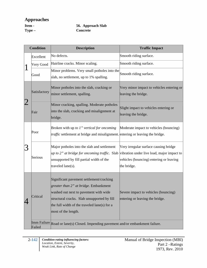
2-142 Manual of Bridge Inspection (MBI)Part 2 –Ratings
1973, Rev. 2010
Condition-rating influencing factors: Location, Extent, Severity, Weak Link, Rate of Change
Approaches Item - 56. Approach Slab Type –
Concrete
Condition Description Traffic Impact
1
Excellent No defects. Smooth riding surface.
Very Good Hairline cracks. Minor scaling. Smooth riding surface.
Good Minor problems. Very small potholes into the
slab, no settlement, up to 1% spalling. Smooth riding surface.
2
Satisfactory Minor potholes into the slab, cracking or
minor settlement, spalling.
Very minor impact to vehicles entering or
leaving the bridge.
Fair
Minor cracking, spalling. Moderate potholes
into the slab, cracking and misalignment at
bridge.
Slight impact to vehicles entering or
leaving the bridge.
3
Poor Broken with up to 1” vertical for oncoming
traffic settlement at bridge and misalignment.
Moderate impact to vehicles (bouncing)
entering or leaving the bridge.
Serious
Major potholes into the slab and settlement
up to 2” at bridge for oncoming traffic. Slab
unsupported by fill partial width of the
traveled lane(s).
Very irregular surface causing bridge
vibration under live load, major impact to
vehicles (bouncing) entering or leaving
the bridge.
4
Critical
Significant pavement settlement/cracking
greater than 2” at bridge. Embankment
washed out next to pavement with wide
structural cracks. Slab unsupported by fill
the full width of the traveled lane(s) for a
most of the length.
Severe impact to vehicles (bouncing)
entering or leaving the bridge.
Imm Failure Road or lane(s) Closed. Impending pavement and/or embankment failure. Failed

2-143 Manual of Bridge Inspection (MBI)Part 2 –Ratings
1973, Rev. 2010
Condition-rating influencing factors: Location, Extent, Severity, Weak Link, Rate of Change
Approaches Item - 57. Guardrail Type –
All
Check for integrity of posts and condition of the rail panels.
Condition Deficiencies Alignment
1 Excellent Guardrail is free from deficiencies. Minor discoloration.
Very Good No noteworthy deficiencies, which affect the condition of the guardrail.
Good Minor deficiencies, which affect the condition of the guardrail.
Misalignment of one or two guardrail posts.
2
Satisfactory
Minor collision damage; minor decay of posts; Guardrail panels are very rusty; Several blockouts, connections are missing.
Misalignment of up to 3 posts in a row.
Fair
Moderate collision damage; 20% loss of section of posts due to decay or missing connections; Several guardrail panels are not attached to posts.
Misalignment of up to 5 posts in a row.
3
Poor
Collision damage; 30% loss of section of posts due to decay or missing connections; Several guardrail panels are not attached to posts.
Misalignment of up to 6 posts in a row.
Serious
Major collision damage; 50% loss of section of posts due to decay or missing connections; Several guardrail panels are not attached to posts.
Misalignment of more than 6 posts in a row.
4 Critical Guardrail is no longer functioning; Major decay of posts (90%).
Imm Failure Guardrail partially collapsed.
Failed Total failure guardrail.

2-144 Manual of Bridge Inspection (MBI)Part 2 –Ratings
1973, Rev. 2010
Condition-rating influencing factors: Location, Extent, Severity, Weak Link, Rate of Change
Approaches Item - 58. Relief Joints Type –
All
Condition Description
1
Excellent No noticeable defects.
Very Good Hairline cracks. Minor scaling.
Good Minor problems. Very small potholes, no settlement.
2
Satisfactory Minor deterioration, minor potholes, cracking or minor settlement.
Fair Minor cracking, spalling. Moderate potholes, cracking, with settlement and misalignment.
3
Poor Broken with settlement and misalignment. (ex. up to 1”)
Serious Major potholes and settlement or bulging. (ex. up to 2”)
4
Critical
Significant settlement or bulging. (ex. more than 2” and cracking) Imm Failure
Failed

2-145 Manual of Bridge Inspection (MBI)Part 2 –Ratings
1973, Rev. 2010
Condition-rating influencing factors: Location, Extent, Severity, Weak Link, Rate of Change
Approaches Item - 59. Embankment Type –
All
The general condition of the approach embankment shall be inspected for indications of settlement,
slipping, sloughing, slide failures, tension cracks in the asphalt, and erosion.
Condition Rutting/Erosion General
1 Excellent No noteworthy deficiencies which affect the condition of the
embankment up to 30 feet away from the structure.
Very Good Minor rutting from drainage. Vegetation intact.
Good Moderate rutting from drainage. Minor amount of bare soil exposed.
2 Satisfactory Minor erosion caused by drainage.
Fair
Erosion caused by drainage or channel; Erosion to embankment impacting guardrail performance or encroaching on shoulder.
Evidence of foundation settlement.
3 Poor
Major erosion caused by drainage or channel; Erosion to embankment impacting guardrail performance or encroaching on shoulder.
Evidence of foundation settlement.
Serious Shoulder eroded away, shoulder closed.
Guardrail post anchor undermined greater than 3 posts in a row
4 Critical Several guardrail posts are
hanging due to major erosion.
A lane of traffic is closed due to embankment failure. Tension cracks in asphalt due to embankment movement.
Imm Failure Embankment failure, lane, shoulder closed or blocked off.
Failed Embankment failed. Road Closed.

2-146 Manual of Bridge Inspection (MBI)Part 2 –Ratings
1973, Rev. 2010
Condition-rating influencing factors: Location, Extent, Severity, Weak Link, Rate of Change
Approaches Item - 60. SUMMARY Type –
All
APPROACHES 55. Pavement 56. Approach Slabs 57. Guardrail 58. Relief Joint 59. Embankment 60. SUMMARY
It is a conversion of the 1-4 items depending upon how they affect the safety and rideability on and off of
the structure. These items include everything to and including the relief joints. If no relief joints exist
then include up to the end of the approach slab; where no slab exist include up to 30-feet off each end of
the structure.
1-4 Individual Items are based on the WORST APPROACH while the 9-0 Summary Items includes ALL
APPROACHES.
1-4 INDIVIDUAL 9-0 SUMMARY
1 9-Excellent
8-Very Good
7-Good
2 6-Satisfactory
5-Fair
3 4-Poor
3-Serious
4 2-Critical
1-Imminent Failure
0-Failed

2-147 Manual of Bridge Inspection (MBI)Part 2 –Ratings
1973, Rev. 2010
Condition-rating influencing factors: Location, Extent, Severity, Weak Link, Rate of Change
GENERAL
GENERAL 61. Navigation Lights 62. Warning Signs 63. Sign Supports 64. Utilities 65. Vertical Clearance (1, 2-change, N) 66. General Appraisal & Op. Status
Grayed boxes are not 1-4 ratings.
General Item - 61. Navigation Lights Type –
All
Determine whether all required navigation lights are operating and properly attached. Examine the
lighting fixtures for condition, visibility, electrical connections and security of attachment to insure
uninterrupted service.
Condition Lighting
1 Excellent
All lights operating, no repairs necessary to system. Very Good
Good
2 Satisfactory All lights operating, however, mounting brackets may need attention or
wiring conduit may be partially disconnected. Fair
3 Poor
All lights operating, however lenses may be broken, connections not secure. Serious
4 Critical
Some lights burnt out or wiring circuitry non-functioning or both, connections
not secure with imminent or permanent failure. Imminent Failure
Failed

2-148 Manual of Bridge Inspection (MBI)Part 2 –Ratings
1973, Rev. 2010
Condition-rating influencing factors: Location, Extent, Severity, Weak Link, Rate of Change
General Item - 62. Warning Signs Type –
All
Warning signs are typically Yellow and Black, inspect for legibility and condition, including any advance
warning signs specific to the bridge. Take photos and notes of signs when discrepancies exist. These
include the Z-board or chevron end markers. Two-way traffic on a structure that has narrowing bridge
railing within 8-feet from the traveled lane will have one chevron sign on each corner.
Refer to the OMUTCD for further details.
Condition Description
1
Excellent
All signs proper and legible. Very Good
Good
2 Satisfactory
Signs faded, bent, minor damage.
Fair
3 Poor
Signs barely legible due to vandalism or fading or partial
obstructions. Serious
4
Critical Signs are missing or at least one end marker is not present (these are
generally used when bridge railing is within 8-feet of the oncoming
traffic lane(s)) or not legible.
Imminent Failure
Failed

2-149 Manual of Bridge Inspection (MBI)Part 2 –Ratings
1973, Rev. 2010
Condition-rating influencing factors: Location, Extent, Severity, Weak Link, Rate of Change
General Item - 63. Sign Supports, 64. Utilities Type – All
Sign Supports
All bridge mounted sign supports will be inspected for deterioration and security of connection.
The sign inspections will be primarily visual with advanced NDT being required only if a defect is first
noted visually. The inspections should concentrate primarily on the sign support anchor bolts. The
attachments for signs attached to the outside of parapets should also be inspected for integrity including
vibration, cracks, loose nuts or missing nuts. Attachments or connections not easily accessible within
"arm's reach" should be "eyeballed" or inspected with binoculars from the bridge deck. It is not expected
that the Inspector climb the sign supports to perform the inspection. However, any defects noted as a
result of the above-noted actions should be inspected carefully or immediately reported to the appropriate
personnel for a hands-on inspection.
Utilities & Access Systems
All bridge mounted utility supports for gas, electric, water, telephone, lighting, etc. will be inspected
for deterioration and security of connection. Additionally, the utilities themselves should be inspected for
deterioration, loose connections, bare wires, etc. Any defects, major leaks, odors etc. noted should be
reported to the appropriate utility owner. The Inspector should compare the utilities on the bridge with the
pre-printed inventory information and if changes are necessary, the inventory should be changed after
returning to the office. Also include condition ratings on Catwalks, Access Systems, Hatches, etc.
Description
1 Excellent Very Good No problems noted. Good Some minor problems.
2 Satisfactory Structural elements show some minor deterioration.
Fair All primary structural elements are sound but have minor section loss, deterioration or spalling. Small leakage.
3 Poor Advanced section loss, deterioration, spalling or scour
Serious Loss of section, deterioration, spalling or scour has seriously affected primary structural components. Local failures are possible. Fatigue cracks in steel or shear cracks in concrete may be present.
4 Critical
Advanced deterioration of primary structural elements. Fatigue cracks in steel or shear cracks in concrete may be present or scour may have removed substructure support. Unless closely monitored it may be necessary to close the bridge until corrective action is taken. Heavy Leakage affecting structure or environment.
Imminent Failure
Major deterioration or section loss present in critical structural components or obvious vertical or horizontal movement affecting structure stability. Bridge is closed to traffic but correction action may put back in light service.
Failed Out of service - beyond corrective action.

2-150 Manual of Bridge Inspection (MBI)Part 2 –Ratings
1973, Rev. 2010
Condition-rating influencing factors: Location, Extent, Severity, Weak Link, Rate of Change
General Item - 65. Vertical Clearance Type – All
Indicate if a vertical clearance restriction exists for vehicular traffic which passes either on or below the
bridge.
Vertical Clearance: Recommendation for low clearance signs on state highways: shall be used to warn
users of clearances less than or equal to 14’-6”. The sign should display up to 3” less than the actual
clearance to account for frost action and reductions (ORC 5577.05 and OMUTCD 2C.2))
Record the actual minimum vertical clearance within the traveled lanes in the comment section and
compare with the inventory. Take photos of signs and update the BMS inventory accordingly where
discrepancies exist. See the part 1 for further information.
1 A restriction exists below the bridge. (25' or less) with no change since the
last inspection.
2 The restriction changed since the last inspection or the obstruction is lower
than the posted sign (ie. due to resurfacing or bridge hit).
N Does not apply (ie. no highways underneath structure).

2-151 Manual of Bridge Inspection (MBI)Part 2 –Ratings
1973, Rev. 2010
Condition-rating influencing factors: Location, Extent, Severity, Weak Link, Rate of Change
General Item - 66. General Appraisal Type –
Simply choose the lowest rating of either the
SUPERSTRUCTURE SUMMARY
SUBSTRUCTURE SUMMARY
OR
CULVERT SUMMARY
This is a two part item. The first box is for coding the general, overall condition of the bridge. The
general appraisal will be based on the existing condition of the bridge as compared to its as-built
condition. The load carrying capacity will not be used in evaluating condition items. Portions of bridges
that are being supported or strengthened by temporary members will be rated based on their actual
condition, i.e. the temporary members are not considered in the rating of the item. The fact a bridge was
designed for less than current legal loads and may be posted will have no influence upon condition
ratings.
Note that these SUMMARIES are 9-0 based on the total bridge and the 1-4 INDIVIDUAL boxes are from
the worst span.
The second box is for coding the operational status of the bridge. See the next page for a description of
Operational Status.

2-152 Manual of Bridge Inspection (MBI)Part 2 –Ratings
1973, Rev. 2010
Condition-rating influencing factors: Location, Extent, Severity, Weak Link, Rate of Change
General Item - 66. Operational Status Type –
The operational status of the bridge should be coded using the following:
"A" Open, no restriction
"B" Open, posting recommended but not legally implemented (all signs not in place)
Load Posting Signs: Verify that the Load Rating Sign matches the posted
signage. Record the signed load posting in tonnage in the comments and
compare with the inventory. If changes exist then update the BMS inventory.
“C” Under construction, half of the existing bridge is open to traffic (half-width construction)
"D" Open, would be posted or closed except for temporary shoring, etc. to allow for
unrestricted traffic
"E" Open, temporary structure in place to carry legal loads while original structure is closed
and awaiting replacement or rehabilitation.
"G" New structure not yet open to traffic
"K" Bridge closed to all traffic
"P" Posted for load-carrying capacity restriction (may
include other restrictions)
Load Posting Signs: Verify that the Load
Rating Sign matches the posted signage. State
Routes are posted on the Operating Rating
when the rating factor is less than 92.5%.
Record the signed load posting in tonnage in
the comments and compare with the inventory.
If changes exist then update the BMS.
"R" Posted for other than load-carrying capacity restriction
(speed, number of vehicles on bridge, etc.).
"X" Bridge closed for reasons other than condition or load-carrying capacity.

2-153 Manual of Bridge Inspection (MBI)Part 2 –Ratings
1973, Rev. 2010
Condition-rating influencing factors: Location, Extent, Severity, Weak Link, Rate of Change
General Item - 67. Inspected By
Type – NBIS Team Leader (at minimum)
Only qualified NBIS Team Leaders may sign an inspection form (example: ODOT BS2, NBIS Team
Leaders, NBIS Program managers etc.). Inspection program qualifications may be found in MBI Part 1.
Inspection shall be performed on each bridge on an annual basis with the time between inspections no
greater than 18 months. Data is downloaded from BMS in March of each year to determine compliance
of this item for the previous year’s annual inspection.
Signature - The inspector is to sign the inspection report and print their name below the signature
PE Number - Beneath the signature line are six boxes, if the inspector is a registered professional
engineer, the inspector shall print their P.E. number in the spaces provided. A reviewer will not
be necessary if the Inspector has a P.E. license and satisfies the definition of an NBIS Team
Leader.
Initials - Code the first, middle and last initial in the appropriate boxes.
Date - The inspector is to fill in the date of the inspection as the day they were in the field. For
multi-day inspections code this date as the day the Team Leader left the bridge site.
Note from Part 1 Section 3.2.2:
“Areas/elements that may be more difficult to access but that warrant hands-on inspection in each Routine
Inspection, may include, but are not limited to:
• Load carrying members in Poor
condition.
• Redundancy retrofit systems.
• Critical sections of controlling
members on posted bridges.
• Scour critical substructure units.
• End regions of steel girders or
beams under deck joints.
• Cantilever portions of concrete piers
or bents in Fair or worse condition.
• Ends of Prestressed concrete beams
at continuity diaphragms when
warranted by Program Manager.
• Pin and Hanger / Hinge assemblies
• Other areas determined by the
Program manager of the inspection
to be potentially critical”.

2-154 Manual of Bridge Inspection (MBI)Part 2 –Ratings
1973, Rev. 2010
Condition-rating influencing factors: Location, Extent, Severity, Weak Link, Rate of Change
General Item - 68. Reviewed By
Type – NBIS Program Manager with PE (at minimum)
Only qualified NBIS Program Managers with a PE (Reviewers) may sign an inspection form within this
item. Inspection program qualifications may be found in MBI Part 1. Report reviews must be submitted
into BMS within 90 days after the field inspection for state structures, and within 180 days for county and
municipal structures. Annual uploads are submitted to FHWA in March of every year to verify
compliance of the previous year’s inspections.
Signature - The reviewer is to sign the inspection report
PE Number - A reviewer must be a professional engineer registered in the State of Ohio and
satisfy the NBIS Program Manager qualifications.
Initials - Code the first, middle and last initial in the appropriate boxes.
Date - The reviewer is to fill in the date of the review. In cases where the inspection is performed
by a consultant, print the name of the firm below the P.E. number box.
The reviewed date must always be after the inspected date. Reviewers are looking for continuity,
consistency, maintenance needs, programming needs, items to monitor, dates out of compliance etc.

2-155 Manual of Bridge Inspection (MBI)Part 2 –Ratings
1973, Rev. 2010
Condition-rating influencing factors: Location, Extent, Severity, Weak Link, Rate of Change
General Item - 69. Survey Boxes 1-4
Type – Safety Features - General
Code Description
0 - Inspected feature does not meet currently acceptable standards or a safety feature is required and
none is provided.
1 - Inspected feature meets currently acceptable standards.
N - Not applicable or a safety feature is not required.
Ohio DOT has set standards in the Bridge Design Manual (BDM), OMUTCD, L&D Manual along with
Standard Drawings. These manuals will supersede these guidelines when discrepancies exist. Collision
damage or deterioration of the elements is not considered when coding this item.
The following guidelines within this manual give direction to inspectors coding these items who do not
have design criteria such as accident history, crash level standards etc. readily available in the field.
Where design analysis, geometry and LON calculations have been performed they will govern over these
guidelines. Write in the comments if deviations have been made from these guidelines. Specific
questions may be directed to the ODOT Roadway Services Engineer or the Bridge Inspection Engineer.
In general, railings that meet the following criteria and loading conditions are considered acceptable
(code=1):
• Proper height, material, strength, and geometric features.
• Smoothly redirecting an impacting vehicle.
• Functioning as designed.
• AASHTO Standard Specifications and the NCHRP 350 report (See the following guidance as it pertains).

2-156 Manual of Bridge Inspection (MBI)Part 2 –Ratings
1973, Rev. 2010
Condition-rating influencing factors: Location, Extent, Severity, Weak Link, Rate of Change
General Item - 69. Survey – Box 1
Type – Bridge Railing - 3 Steps Step 1 – If there is no railing then Code N or 0. Code N if there is at least 24-inches of fill (ie. Culvert) and, for the purposes of this manual, the unobstructed clear zone, with no horizontal curvature, is more than 30-feet (Consider the L&D section 600 to verify as the clear zone may change based on other factors). Step 2 – If there is a Rail Code 1 or 0. Note the material, type and measure the height of the bridge rail. Verify with the two types below:
• Most JB or single slope concrete barriers are crash tested to NHS, code 1. Only the concrete GM barrier (it is 32” high and the base extension is 15” high and 9” wide) is not standard – Code 0.
• Thrie-beam retrofits over safety curb barriers are crash tested NHS – Code 1. Step 3 – Verify from the bridge rails in the table below and verify that the rail fulfills the criteria in the adjacent columns. If the criteria is met, then code 1Standard. If the bridge rail is not listed or if the criteria is not met then most likely it will be coded 0-Not standard. Important note: an old standard not acceptable on heavier routes may be acceptable on another route because of its lower TL. When a railing is in question please refer to the Ohio BDM, MUTCD, L&D Manual or standard drawings.
*Sidewalk must be > 5’ wide and curb 8” high or less
Type (verify type and measure ht) Route On Lanes
Route Under
ADTT Single
Direction
Deck Height Above Ground
line 42" Single Slope Barrier State or
Interstate (on or over)
2 or more
State or Interstate
(also acceptable over rural streams)
>2500
>25'
42" Jersey Barrier 2 or more
36" Jersey Barrier 2
<2500
24-32” Vertical Concrete Barrier with Sidewalk* & Curb with Tubing Rural,
Local Streets
2 or more
At least 32” Vertical Concrete Barrier with Sidewalk & Curb*
2 or more
31.5” Twin Steel Tube Rail State or
Interstate 2
Rural Streams
<25' 27” Deep Beam Rail (W-Beam backed with Steel Beam)
Rural, Local Streets
2
27” Long Span Guardrail State
Routes
Other: Ensure 3’-7”clearance behind the face of the rail
27” 25-foot Span Guardrail State
Routes
Other: Ensure 5’-0”clearance behind the face of the rail

2-157 Manual of Bridge Inspection (MBI)Part 2 –Ratings
1973, Rev. 2010
Condition-rating influencing factors: Location, Extent, Severity, Weak Link, Rate of Change
General Item - 69. Survey – Box 2
Type – Transitions – Bridge Terminal Assemblies (BTA) - 4 Steps Step 1 – If a BTA exists code 1 or 0. Skip to step 4 if a BTA exists. Step 2 - If a BTA is not present (Code 0 or N) and the posted speed limit is less than or equal to 30mph code N (note: BTA’s are generally not needed for speeds up to 50mph on straight roadways, however accident history and roadway geometry information is not readily available to the inspector). If the speed limit is less than or equal to 50mph and there is a straight roadway alignment and no BTA exists then code N. If speed limits are greater than 30 with a horizontal curve and no BTA exists then code 0. If speeds are greater than 50mph and no BTA exists code 0. Step 3 – For the vast majority of cases: Code N if Box 1 is correctly coded N and code 0 if Box 1 is correctly coded 0 and speed limits are above 50 mph or between 30 and 50mph with a horizontal curve. Where an impact attenuator exists code N. Step 4 - Note the material, type and verify a positive connection at the bridge rail. Verify that the bridge type is one of the six in the table below with the listed criteria. If the bridge rail is not listed below, then code 0-not to standard.
Type 1 Approach End Thrie
beam GR-3.1
(curb shown)
Type 2 W-beam GR-3.2
(trailing end only) Trailing End W-beam (looks like a Type 5
guardrail)
Type 3 Asymmetrical GR-3.3
Asymmetrical Thrie beam design for TBR railing
Type 1- Barrier GR-3.5
Approach End Thrie beam, barrier design (two sided)
Type TST GR-3.6
Twin Steel Tube BTA for the TST railing
Type 4 W-beam GR-3.4
W-beam BTA for DBR railings, or Guardrail with Tubular
Backup

2-158 Manual of Bridge Inspection (MBI)Part 2 –Ratings
1973, Rev. 2010
Condition-rating influencing factors: Location, Extent, Severity, Weak Link, Rate of Change
General Item - 69. Survey – Box 3
Type – Approach Guardrail - 3 Steps Step 1 – Code 0 or 1 where approach rail exists. Code 1 for type B, C, D when height is:
Step 2 - Most culverts require a barrier, therefore code culverts 1 or 0 unless, on a straight roadway the clear zone is more than 30-ft; then conservatively code N Step 3 – Code depending on height, fill depth and deflection. Code 1 if type 5 or 5A meet the following:
Height: should be between 27” and 29”. Fills: less than 2.5’ at the rail shall be bolted to the precast frame, fills between 2.5’ and 3.5’ shall be grouted and fills deeper than 3.5’ posts can be embedded into the fill. Deflection: tolerance for post spacing shall follow the chart below:
Barrier Type Std. Dwg. Deflection Post Spacing
*measured from the face of the barrier to the obstacle

2-159 Manual of Bridge Inspection (MBI)Part 2 –Ratings
1973, Rev. 2010
Condition-rating influencing factors: Location, Extent, Severity, Weak Link, Rate of Change
General Item - 69. Survey – Box 4
Type – Approach Guardrail Ends - 4 Steps Step 1 – Where an approach guardrail does not terminate within 100’ of the structure off the bridge then code N (note: walking limits are the longest of the three – relief joint or approach slab or 30’ however the inspector must site down the railing where terminations exist between the walking limits and 100’). Step 2 – Where a properly installed, acceptable impact attenuator exists code 1. Where box 3 is coded N because the transition is directly connected to the “end” type skip to step 3. Where no impact attenuator exists and survey box 3 has an N code N. Step 3 – Where box 3 is correctly coded 0, code box 4 the same. Code 1 when any of the 8 types shown exist with the appropriate criteria.
Type A, in clear zone on non NHS for low-speed,
or <4000VPD
Type T Trailing end only
Guardrails with a radius at driveways or side
roads
Guardrail Type 8 Has rubrail
Type 1 Type B
(SRT shown) Type E
(ET shown) Impact Attenuator (Type 2 shown)
Step 4 - Code 0 where one of the 4 Unacceptable rails below are present with criteria. All others not satisfied in the above criteria also code 0.
Unacceptable Anchors and End Terminals (partial listing)
Type A
in high speed clear zone
Old SCD GR-4.3M, Type B, not newer
(identified by no slots in w-beam rail)
Type T in clear zone of traffic
(opposing traffic shown)
Buried in backslope without rubrail

2-160 Manual of Bridge Inspection (MBI)Part 2 –Ratings
1973, Rev. 2010
Condition-rating influencing factors: Location, Extent, Severity, Weak Link, Rate of Change
General Item - 69. Survey – Box 5
Type – In-Depth Inspection Code Description
0 - In-Depth Inspection was performed for only a portion of the primary members
1 - In-Depth Inspection was performed for all primary members
N - Not applicable or a safety feature is not required.
Details for in-depth inspections can be found in Part 1 of this manual in section 3.3.
General Item - 69. Survey – Box 6
Type – Fracture Critical Inspection (FCM) Code Description
0 - FCM Inspection was performed BUT no FCM/FPD plan exists for the inspector to reference
1 - FCM Inspection was performed and the FCM/FPD plan exists for the inspector to reference
N - Not applicable
Details for FCM inspections can be found in Part 1 of this manual in section 3.7 and the Appendix
General Item - 69. Survey – Box 7
Type – Scour Critical Plan of Action (POA) Code Description
0 - Bridge Scour Plan of Action NOT yet completed or NOT yet implemented (ie. the self-
recommended actions have not been put into operation)
1 - Bridge Scour Plan of Action Completed and Implemented (necessary for U, 3, 2, 1 and 0’s for
inventory item 74). See Part 1 of this manual and the appendix for guidance.
N – Not applicable (POA NOT necessary for inventory item 74 coded 9, 8, 7, 5, 4, N or T)
Details for waterway items are in Part 1 sections 3.8-3.10, inventory item #74 and the Appendix

2-161 Manual of Bridge Inspection (MBI)Part 2 –Ratings
1973, Rev. 2010
Condition-rating influencing factors: Location, Extent, Severity, Weak Link, Rate of Change
General Item - 69. Survey – Box 8
Type – Critical Finding Code Description
0 – NO– Critical Finding was discovered but NOT repaired since last inspection.
1 – YES - Critical Finding was found on the bridge. A critical bridge deficiency involves a
situation discovered during any inspection of a bridge that if not promptly corrected, could cause
failure or partial failure of a bridge, or could pose a serious traffic safety hazard. Any of the
following inspection findings must be reported immediately:
• Bridge with recommendations for immediate action (example within one week) on any
Fracture Critical Member.
• Bridge with recommendations for immediate (example within 1 week) correction of scour
or hydraulic problems.
• Bridges with recommendations for immediate (example within 1 week) work to prevent
substantial reduction in safe load capacity.
• Bridges with condition ratings lowered to a value of 2 or less on the 9-0 scale for items:
Deck Summary, Superstructure Summary, Substructure Summary, Culvert Summary,
Channel Summary or Approach Summary.
Record and send the description of the critical findings, immediate action taken to ensure the
safety of the traveling public and current plan of action (POA) and sketches or photos to
Office of Structural Engineering.
c/o Bridge Inspection Engineer
1980 W. Broad Street
Columbus, Ohio 43214
N – Not applicable -Where Critical findings are reported one year but repaired the next year
inspectors may then change the code to N-Not Applicable if the finding was remedied.

2-162 Manual of Bridge Inspection (MBI)Part 2 –Ratings
1973, Rev. 2010
Condition-rating influencing factors: Location, Extent, Severity, Weak Link, Rate of Change
BR-86 Supplemental Item - 68- 71
Type – Suspension Bridges
If inspecting a suspension or moveable bridge, two forms must be used. The applicable Items on the
standard BR-86 form are to be filled out as well as the BR-86S Supplemental form. For copies of the
supplemental form, please contact the District Bridge Engineer or find blank ones on the ODOT Office of
Structural Engineering website. These items will be coded on the 1-4 Scale (Good, Fair, Poor, Critical)
Suspension Bridge
Item 68. Main Cables
The large cables or eyebar chains which are draped over the towers and bent posts and from which the
superstructure is suspended from make up the main cables. Check these cables for evidence of broken
wires and leakage from within. Occasionally (once every 10 years) portions of the main cables should be
unwrapped and checked for the above noted deficiencies as well as general condition (paint, rust, etc.).
Item 69. Suspenders
The generally vertical wire cables, metal rods or bars designed to engage a cable band or other device
connecting them to the main suspension cable at one end and to the suspended superstructure at the other
end, thus permitting them to assist in supporting the bridge floor system and it’s superimposed loads by
transferring loads to the main suspension members of the structure. The suspenders support other
members against sagging, twisting, or other deformation due to its own weight. Check for worn or
broken wires and relative tension in adjacent suspenders.

2-163 Manual of Bridge Inspection (MBI)Part 2 –Ratings
1973, Rev. 2010
Condition-rating influencing factors: Location, Extent, Severity, Weak Link, Rate of Change
BR-86 Supplemental Item - 71-77
Type – Suspension Bridges
Item 70. Cable Bands
The clamps are around the main cables over which the suspenders are looped. Check for missing bolts,
looseness of band, and evidence of downhill slippage, lack of caulking between bands and main cables,
and rotation of the band on the main cable.
Item 71. Suspender Connections
The suspender ends or sockets which are attached to the superstructure. Look for evidence of
disintegrated or frayed wires at the sockets. Also check the integrity of the bracket which is attached to
the superstructure. Look for affects from debris and rust-through of any connections in the splash zone.
Item 72. Towers
A large pier or frame extending well above the roadway and serving to support the cables or chains of a
suspension type bridge at the ends of the main span. Check the base connections for integrity. Carefully
check all areas subject to drainage and splash.
Item 73. Tower Saddles
The saddles at the top of the towers in which the main cables rest. Check for evidence of movement of the
main cable within the saddle and proper caulking.
Item 74. Bent Posts
The shorter towers at the ends of the bridge which support the main cable or chain. Generally, the cable
or chain is nearly horizontal at this point and then abruptly changes direction and goes immediately down
to the anchorages. Check for evidence of movement, deterioration in the splash zone. and integrity of the
base connections.
Item 75. Anchorage
The point at which the cable or chain terminates in the foundation. Check for broken and rusted wires
where they are splayed and looped around pins and eyebars. Also check eyebars for section loss where
they are embedded in the concrete. Check for unusual dampness or standing water.

2-164 Manual of Bridge Inspection (MBI)Part 2 –Ratings
1973, Rev. 2010
Condition-rating influencing factors: Location, Extent, Severity, Weak Link, Rate of Change
BR-86 Supplemental Item - 78-90
Type – Movable Bridges
Item 77. Summary 1-4 Individual Items are based on the WORST SPAN while the 9-0 Summary
Items include ALL SPANS using the conversion 9-0, 1-4 conversion.
Items 78. - 99.
Refer to "Bridge Inspector's Manual For Movable Bridges", 1977, U.S. Department Of Transportation,
Federal Highway Administration, for descriptions.
Item 78. Gears - Check for misalignment; tooth wear; evidence of lubrication.
Item 79. Shafts - Check for wear; vibration; cracks.
Item 80. Bearings - Check for evidence of wear; vibration; adequate lubrication.
Item 81. Electric Motors - Make continuity/resistance tests.
Item 82. Auxiliary Engines - Check for ease of starting; lubrication.
Item 83. Center Locks - Check for proper engagement, lubrication, wear, cracks.
Item 84. Tail Locks - Check for proper engagement, lubrication, wear, cracks.
Item 85. Reducers - Check for lubrication, gear alignment, tooth wear.
Item 86. Couplings - Check for tightness.
Item 87. Wire Ropes - Check for broken or frayed ropes.
Item 88. Sockets - Check for evidence of slippage; corrosion of wire rope where it enters socket.
Item 89. Span Balance - Check for smoothness of operation, excessive impact upon closure.

2-165 Manual of Bridge Inspection (MBI)Part 2 –Ratings
1973, Rev. 2010
Condition-rating influencing factors: Location, Extent, Severity, Weak Link, Rate of Change
BR-86 Supplemental Item - 91-99
Type – Movable Bridges
Item 90. Buffers - Check for proper operation, excessive wear, fluid leakage.
Item 91. Brakes - Check for wear.
Item 92. Transformers - Check for leakage; make appropriate electrical tests.
Item 93. Circuit Breakers - Test for proper operation.
Item 94. Limit Switches - Test for proper operation.
Item 95. Traffic Gates/Lights - Check operation, visibility, damage, wear.
Item 96. Lubrication - Check for evidence of proper lubrication, presence of dirt in grease.
Item 97. General Operation - Check for smoothness of operation, housekeeping.
Item 99. Summary – 1-4 Individual Items are based on the WORST SPAN while the 9-0 Summary
Items include ALL SPANS using the conversion 9-0, 1-4 conversion.


APPENDIX
A. Reference Manuals
B. Title 23 Code of Federal Regulations (CFR) Part 650 Subpart C
C. Ohio Revised Code (ORC) - Bridge Inspection
D. Confined Space Flow Chart & Confined Space Alternate Entry Form
E. Fatigue Categories
F. FCM and FPD Report Example
G. Scour Critical Susceptibility Plan of Action (POA) Template
H. Scour Critical Assessment Checklist
I. Cross Channel Profile Measurements
J. Quality Assurance Review (QAR) Form
K. Critical Finding Report
L. Pin and Hanger Detailed Inspection Form
M. Movable Bearing Detailed Inspection Form
N. Damage Inspection – 4SR7 Funds & Extent /Severity for over-height
bridge hits on steel beam superstructure bridges
O. Measurements of Corrugated Metal Culverts
P. Glossary of Bridge Inspection Terms
Q. Inventory & Inspection Forms

Appendix A Reference Manuals
1. Publication No. FHWA NHI 03-001, Bridge Inspector=s Reference Manual, October 2002.
2. The Manual for Bridge Evaluation, American Association of State Highway and Transportation Officials, first Edition 2008
3. Manual for Condition Evaluation of Bridges, American Association of State Highway and Transportation Officials, second Edition with 2001 and 2003 interims
4. Manual for Condition Evaluation of Bridges, Load and Resistance Factors Rating (LRFR), American Association of State Highway and Transportation Officials, 2003
5. Recording and Coding Guide for the Structure Inventory and Appraisal of the Nation’s Bridges, Federal Highway Administration, 1995 with revision 2000
6. Bridge Inventory and Appraisal Coding Guide, Ohio Department of Transportation, 1989, with revision 2009
7. FHWA/NCHRP reports supplementing bridge inspection training guidelines
www.national-academies.org/trb/bookstore

Appendix B
Title 23 Code of Federal Regulations (CFR) Part 650 Subpart C

Title 23: Highways CFR 650
PART 650—BRIDGES, STRUCTURES, AND HYDRAULICS
Subpart C—National Bridge Inspection Standards
Source: 69 FR 74436, Dec. 14, 2004, unless otherwise noted.

§ 650.301 Purpose.
This subpart sets the national standards for the proper safety inspection and evaluation of all highway bridges in accordance with 23 U.S.C. 151.
§ 650.303 Applicability.
The National Bridge Inspection Standards (NBIS) in this subpart apply to all structures defined as highway bridges located on all public roads.
§ 650.305 Definitions.
Terms used in this subpart are defined as follows:
American Association of State Highway and Transportation Officials (AASHTO) Manual . “Manual for Condition Evaluation of Bridges,” second edition, published by the American Association of State Highway and Transportation Officials (incorporated by reference, see §650.317).
Bridge. A structure including supports erected over a depression or an obstruction, such as water, highway, or railway, and having a track or passageway for carrying traffic or other moving loads, and having an opening measured along the center of the roadway of more than 20 feet between undercopings of abutments or spring lines of arches, or extreme ends of openings for multiple boxes; it may also include multiple pipes, where the clear distance between openings is less than half of the smaller contiguous opening.
Bridge inspection experience. Active participation in bridge inspections in accordance with the NBIS, in either a field inspection, supervisory, or management role. A combination of bridge design, bridge maintenance, bridge construction and bridge inspection experience, with the predominant amount in bridge inspection, is acceptable.
Bridge inspection refresher training. The National Highway Institute “Bridge Inspection Refresher Training Course”1 or other State, local, or federally developed instruction aimed to improve quality of inspections, introduce new techniques, and maintain the consistency of the inspection program.
1 The National Highway Institute training may be found at the following URL: http://www.nhi.fhwa.dot.gov./
Bridge Inspector's Reference Manual (BIRM). A comprehensive FHWA manual on programs, procedures and techniques for inspecting and evaluating a variety of in-service highway bridges. This manual may be purchased from the U.S. Government Printing Office, Washington, DC 20402 and from National Technical Information Service, Springfield, Virginia 22161, and is available at the following URL: http://www.fhwa.dot.gov/bridge/bripub.htm.
Complex bridge . Movable, suspension, cable stayed, and other bridges with unusual characteristics.
Comprehensive bridge inspection training. Training that covers all aspects of bridge inspection and enables inspectors to relate conditions observed on a bridge to established criteria (see the Bridge Inspector's Reference Manual for the recommended material to be covered in a comprehensive training course).
Critical finding. A structural or safety related deficiency that requires immediate follow-up inspection or action.

Damage inspection. This is an unscheduled inspection to assess structural damage resulting from environmental factors or human actions.
Fracture critical member (FCM). A steel member in tension, or with a tension element, whose failure would probably cause a portion of or the entire bridge to collapse.
Fracture critical member inspection. A hands-on inspection of a fracture critical member or member components that may include visual and other nondestructive evaluation.
Hands-on. Inspection within arms length of the component. Inspection uses visual techniques that may be supplemented by nondestructive testing.
Highway. The term “highway” is defined in 23 U.S.C. 101(a)(11).
In-depth inspection. A close-up, inspection of one or more members above or below the water level to identify any deficiencies not readily detectable using routine inspection procedures; hands-on inspection may be necessary at some locations.
Initial inspection. The first inspection of a bridge as it becomes a part of the bridge file to provide all Structure Inventory and Appraisal (SI&A) data and other relevant data and to determine baseline structural conditions.
Legal load. The maximum legal load for each vehicle configuration permitted by law for the State in which the bridge is located.
Load rating. The determination of the live load carrying capacity of a bridge using bridge plans and supplemented by information gathered from a field inspection.
National Institute for Certification in Engineering Technologies (NICET). The NICET provides nationally applicable voluntary certification programs covering several broad engineering technology fields and a number of specialized subfields. For information on the NICET program certification contact: National Institute for Certification in Engineering Technologies, 1420 King Street, Alexandria, VA 22314–2794.
Operating rating. The maximum permissible live load to which the structure may be subjected for the load configuration used in the rating.
Professional engineer (PE). An individual, who has fulfilled education and experience requirements and passed rigorous exams that, under State licensure laws, permits them to offer engineering services directly to the public. Engineering licensure laws vary from State to State, but, in general, to become a PE an individual must be a graduate of an engineering program accredited by the Accreditation Board for Engineering and Technology, pass the Fundamentals of Engineering exam, gain four years of experience working under a PE, and pass the Principles of Practice of Engineering exam.
Program manager. The individual in charge of the program, that has been assigned or delegated the duties and responsibilities for bridge inspection, reporting, and inventory. The program manager provides overall leadership and is available to inspection team leaders to provide guidance.
Public road. The term “public road” is defined in 23 U.S.C. 101(a)(27).
Quality assurance (QA). The use of sampling and other measures to assure the adequacy of quality control procedures in order to verify or measure the quality level of the entire bridge inspection and load rating program.

Quality control (QC). Procedures that are intended to maintain the quality of a bridge inspection and load rating at or above a specified level.
Routine inspection. Regularly scheduled inspection consisting of observations and/or measurements needed to determine the physical and functional condition of the bridge, to identify any changes from initial or previously recorded conditions, and to ensure that the structure continues to satisfy present service requirements.
Routine permit load. A live load, which has a gross weight, axle weight or distance between axles not conforming with State statutes for legally configured vehicles, authorized for unlimited trips over an extended period of time to move alongside other heavy vehicles on a regular basis.
Scour. Erosion of streambed or bank material due to flowing water; often considered as being localized around piers and abutments of bridges.
Scour critical bridge. A bridge with a foundation element that has been determined to be unstable for the observed or evaluated scour condition.
Special inspection. An inspection scheduled at the discretion of the bridge owner, used to monitor a particular known or suspected deficiency.
State transportation department. The term “State transportation department” is defined in 23 U.S.C. 101(a)(34).
Team leader. Individual in charge of an inspection team responsible for planning, preparing, and performing field inspection of the bridge.
Underwater diver bridge inspection training. Training that covers all aspects of underwater bridge inspection and enables inspectors to relate the conditions of underwater bridge elements to established criteria (see the Bridge Inspector's Reference Manual section on underwater inspection for the recommended material to be covered in an underwater diver bridge inspection training course).
Underwater inspection. Inspection of the underwater portion of a bridge substructure and the surrounding channel, which cannot be inspected visually at low water by wading or probing, generally requiring diving or other appropriate techniques.
§ 650.307 Bridge inspection organization.
(a) Each State transportation department must inspect, or cause to be inspected, all highway bridges located on public roads that are fully or partially located within the State's boundaries, except for bridges that are owned by Federal agencies.
(b) Federal agencies must inspect, or cause to be inspected, all highway bridges located on public roads that are fully or partially located within the respective agency responsibility or jurisdiction.
(c) Each State transportation department or Federal agency must include a bridge inspection organization that is responsible for the following:
(1) Statewide or Federal agencywide bridge inspection policies and procedures, quality assurance and quality control, and preparation and maintenance of a bridge inventory.
(2) Bridge inspections, reports, load ratings and other requirements of these standards.

(d) Functions identified in paragraphs (c)(1) and (2) of this section may be delegated, but such delegation does not relieve the State transportation department or Federal agency of any of its responsibilities under this subpart.
(e) The State transportation department or Federal agency bridge inspection organization must have a program manager with the qualifications defined in §650.309(a), who has been delegated responsibility for paragraphs (c)(1) and (2) of this section.
§ 650.309 Qualifications of personnel.
(a) A program manager must, at a minimum:
(1) Be a registered professional engineer, or have ten years bridge inspection experience; and
(2) Successfully complete a Federal Highway Administration (FHWA) approved comprehensive bridge inspection training course.
(b) There are five ways to qualify as a team leader. A team leader must, at a minimum:
(1) Have the qualifications specified in paragraph (a) of this section; or
(2) Have five years bridge inspection experience and have successfully completed an FHWA approved comprehensive bridge inspection training course; or
(3) Be certified as a Level III or IV Bridge Safety Inspector under the National Society of Professional Engineer's program for National Certification in Engineering Technologies (NICET) and have successfully completed an FHWA approved comprehensive bridge inspection training course, or
(4) Have all of the following:
(i) A bachelor's degree in engineering from a college or university accredited by or determined as substantially equivalent by the Accreditation Board for Engineering and Technology;
(ii) Successfully passed the National Council of Examiners for Engineering and Surveying Fundamentals of Engineering examination;
(iii) Two years of bridge inspection experience; and
(iv) Successfully completed an FHWA approved comprehensive bridge inspection training course, or
(5) Have all of the following:
(i) An associate's degree in engineering or engineering technology from a college or university accredited by or determined as substantially equivalent by the Accreditation Board for Engineering and Technology;
(ii) Four years of bridge inspection experience; and
(iii) Successfully completed an FHWA approved comprehensive bridge inspection training course.
(c) The individual charged with the overall responsibility for load rating bridges must be a registered professional engineer.

(d) An underwater bridge inspection diver must complete an FHWA approved comprehensive bridge inspection training course or other FHWA approved underwater diver bridge inspection training course.
§ 650.311 Inspection frequency.
(a) Routine inspections. (1) Inspect each bridge at regular intervals not to exceed twenty-four months.
(2) Certain bridges require inspection at less than twenty-four-month intervals. Establish criteria to determine the level and frequency to which these bridges are inspected considering such factors as age, traffic characteristics, and known deficiencies.
(3) Certain bridges may be inspected at greater than twenty-four month intervals, not to exceed forty-eight-months, with written FHWA approval. This may be appropriate when past inspection findings and analysis justifies the increased inspection interval.
(b) Underwater inspections. (1) Inspect underwater structural elements at regular intervals not to exceed sixty months.
(2) Certain underwater structural elements require inspection at less than sixty-month intervals. Establish criteria to determine the level and frequency to which these members are inspected considering such factors as construction material, environment, age, scour characteristics, condition rating from past inspections and known deficiencies.
(3) Certain underwater structural elements may be inspected at greater than sixty-month intervals, not to exceed seventy-two months, with written FHWA approval. This may be appropriate when past inspection findings and analysis justifies the increased inspection interval.
(c) Fracture critical member (FCM) inspections. (1) Inspect FCMs at intervals not to exceed twenty-four months.
(2) Certain FCMs require inspection at less than twenty-four-month intervals. Establish criteria to determine the level and frequency to which these members are inspected considering such factors as age, traffic characteristics, and known deficiencies.
(d) Damage, in-depth, and special inspections. Establish criteria to determine the level and frequency of these inspections.
§ 650.313 Inspection procedures.
(a) Inspect each bridge in accordance with the inspection procedures in the AASHTO Manual (incorporated by reference, see §650.317).
(b) Provide at least one team leader, who meets the minimum qualifications stated in §650.309, at the bridge at all times during each initial, routine, in-depth, fracture critical member and underwater inspection.
(c) Rate each bridge as to its safe load-carrying capacity in accordance with the AASHTO Manual (incorporated by reference, see §650.317). Post or restrict the bridge in accordance with the AASHTO Manual or in accordance with State law, when the maximum unrestricted legal loads or State routine permit loads exceed that allowed under the operating rating or equivalent rating factor.
(d) Prepare bridge files as described in the AASHTO Manual (incorporated by reference, see §650.317). Maintain reports on the results of bridge inspections together with notations of any action taken to

address the findings of such inspections. Maintain relevant maintenance and inspection data to allow assessment of current bridge condition. Record the findings and results of bridge inspections on standard State or Federal agency forms.
(e) Identify bridges with FCMs, bridges requiring underwater inspection, and bridges that are scour critical.
(1) Bridges with fracture critical members. In the inspection records, identify the location of FCMs and describe the FCM inspection frequency and procedures. Inspect FCMs according to these procedures.
(2) Bridges requiring underwater inspections. Identify the location of underwater elements and include a description of the underwater elements, the inspection frequency and the procedures in the inspection records for each bridge requiring underwater inspection. Inspect those elements requiring underwater inspections according to these procedures.
(3) Bridges that are scour critical. Prepare a plan of action to monitor known and potential deficiencies and to address critical findings. Monitor bridges that are scour critical in accordance with the plan.
(f) Complex bridges. Identify specialized inspection procedures, and additional inspector training and experience required to inspect complex bridges. Inspect complex bridges according to those procedures.
(g) Quality control and quality assurance. Assure systematic quality control (QC) and quality assurance (QA) procedures are used to maintain a high degree of accuracy and consistency in the inspection program. Include periodic field review of inspection teams, periodic bridge inspection refresher training for program managers and team leaders, and independent review of inspection reports and computations.
(h) Follow-up on critical findings. Establish a statewide or Federal agency wide procedure to assure that critical findings are addressed in a timely manner. Periodically notify the FHWA of the actions taken to resolve or monitor critical findings.
§ 650.315 Inventory.
(a) Each State or Federal agency must prepare and maintain an inventory of all bridges subject to the NBIS. Certain Structure Inventory and Appraisal (SI&A) data must be collected and retained by the State or Federal agency for collection by the FHWA as requested. A tabulation of this data is contained in the SI&A sheet distributed by the FHWA as part of the “Recording and Coding Guide for the Structure Inventory and Appraisal of the Nation's Bridges,” (December 1995) together with subsequent interim changes or the most recent version. Report the data using FHWA established procedures as outlined in the “Recording and Coding Guide for the Structure Inventory and Appraisal of the Nation's Bridges.”
(b) For routine, in-depth, fracture critical member, underwater, damage and special inspections enter the SI&A data into the State or Federal agency inventory within 90 days of the date of inspection for State or Federal agency bridges and within 180 days of the date of inspection for all other bridges.
(c) For existing bridge modifications that alter previously recorded data and for new bridges, enter the SI&A data into the State or Federal agency inventory within 90 days after the completion of the work for State or Federal agency bridges and within 180 days after the completion of the work for all other bridges.
(d) For changes in load restriction or closure status, enter the SI&A data into the State or Federal agency inventory within 90 days after the change in status of the structure for State or Federal agency bridges and within 180 days after the change in status of the structure for all other bridges.
§ 650.317 Reference manuals.
(a) The materials listed in this subpart are incorporated by reference in the corresponding sections noted. These incorporations by reference were approved by the Director of the Federal Register in accordance with 5 U.S.C. 552(a) and 1 CFR part 51. These materials are incorporated as they exist on the date of the approval, and notice of any change in these documents will be published in theFederal Register.The materials are available for purchase at the address listed below, and are available for inspection at the National Archives and Records Administration (NARA). These materials may also be reviewed at the Department of Transportation Library, 400 Seventh Street, SW., Washington, DC, in Room 2200. For information on the availability of these materials at NARA call (202) 741–6030, or go to the following URL: http://www.archives.gov/federal_register/code_of_federal_regulations/ibr_locations.html. In the event there is a conflict between the standards in this subpart and any of these materials, the standards in this subpart will apply.
(b) The following materials are available for purchase from the American Association of State Highway and Transportation Officials, Suite 249, 444 N. Capitol Street, NW., Washington, DC 20001. The materials may also be ordered via the AASHTO bookstore located at the following URL: http://www.aashto.org/aashto/home.nsf/FrontPage.
(1) The Manual for Condition Evaluation of Bridges, 1994, second edition, as amended by the 1995, 1996, 1998, and 2000 interim revisions, AASHTO, incorporation by reference approved for §§650.305 and 650.313.
(2) 2001 Interim Revision to the Manual for Condition Evaluation of Bridges, AASHTO, incorporation by reference approved for §§650.305 and 650.313.
(3) 2003 Interim Revision to the Manual for Condition Evaluation of Bridges, AASHTO, incorporation by reference approved for §§650.305 and 650.313.


Appendix C
Ohio Revised Code (ORC)
5535.01 Classes of Highways 10-01-1953
5501.47 Bridge Inspections 09-28-1973
5543.20 Responsibility for Bridge Insp 09-28-1973
723.54 Inspection of Bridges 11-20-1985
5501.49 Lift Bridge Inspections 06-30-1991;
2007 HB67 07-03-2007

���������������������
���!����������� �������������"����������������#������$��!������$
�������������
%&'(����������!���������������������������������)�
%�'��!����������!����������������)��������������� �����!���
���) � ������"����������������������������$����!�"�$� �����"�������$
����������*���������!������������)�(!����������)����������������� ��!�����))�������
%�' �������������!�����!�������������������������!������� �������
������� ��!������)����� ��!�� ��������� ���������� �� ���� � ��!���
��))������)����������� ���������!�����)����������!������ ��
���������������"����������� ���������!��� ��) �)���"������������������������
+ ����"�,��#��-��-�.��
����������������� ����
%&' ����������� ��������������������� ������������ ����������������������
���) ��������!����� )!����������$������������������/���������������� ��
�������������)���� ���������������������!�������$������������������������
� ������ ������� ������������ ����������� ��� �� ������)�������� �� ��������)����
(!����������������)����!�������� ��������������������0!�� ��������
!�������!���"����� ��� �������������$��)��� ��0!������ ��0!�����������������$�����������������)�!�� ���������������������������"����%�'� ����������
��������������!�����)�������������������� ��������)����!�������"������
� ��������������!�������������������������������)$����!��������������
������ )!����������$�� ������������� ������� ��������)���������������� ��
���������� �� ��"������ ������ ���������� ��� � ��������� ����������� �� ��)��������$�����!������� ��!����������������
/����������������������1��2����)��������������������$�������������� !��������� ������������������������ ������ )���������
34��������5!���������"����)����!���� ��)���� )�����������*�
%�'%�'&!���������"����#
%'3���������5)���������������������������)�!�� �������������������������������)����
%�'36�����5)���������������)���������������� �����"�������$������$
�����$�����������)!����������$���������������$�����$����������������!������"���

%�'3������5)������!��!��� ��� �����)�������������� �����)�������)����
��$��"�$�������������$����!������!��!��!������������������)���"�����)���"���
%�' ��������������"������������������� �����������$��"�������$��)��������
������!�����������������"��� �������)������ ��������������� ������� �������������#
%'7�����$)�����$��!����)�!�� �������������������������"��������
����������������������� ����������$��"�$������� ������� ��)�!����
����!��$�!�������)������$�������������� ��0!����� ���������$0!�� �������
����������������!���"�������������$������!����������� ������������ ��������������� ������8
%�',�"������ !������������� ��)������� ��)������������������$������"�
��)!�������!� ��������)���� ��)8
%�'&������������������"���)����!���$!�����0!��$�������������$���)����
�� ��)�����������������"���)����� �������������������������������������
��������� �������$�� ��� ������ �!����� ������ ���������"��!��� ��������� �
������8!�������)�������� ��) � �������������!������)!���������������� ������������������)��������������"���8
%�'����������������������$����������������������"�� ��������$�������
������������"�������������� ����������������� ����������������� !����������
������ ��������� ��� �������� ���� ��� ������������� �� ��� )�!�� ����������������
+ ����"�,��#�.-�9-�.��
�����!�������"��� ����"��������� ����
����!������������������������������������������� �������!������������)
��������!����� )!����������$������������������$�����������������������
������ ������������������� ����������������������)���������������!�����
��������������� ������������ ���������� �1������ ������)����������!���
��� ��)��� �������� � )�������� �� ������$��������� ����� )�� �� ������������
��������������������������� ���������!��� ��) �����������������������������
(!����������������)����!���$��)��� ��0!������ ��0!�������������� ��!���
��))������$�����������������)�!�� ��������������������������������������
� �����"��������
��!����)�������� �������������"����
�������������)������!�������"������� ���������������!���$�1����������
���������������) ������������)!��������� ����������������������!����
������$�� ������� �� ��� ��"������ ������ ��� � ��������� ����������� �� ��)��������$�����!������� ��!����������������

�������������������������������� ������������������ ��!�����))���������
��������1���� �������!�����������������������)��� ��0!������ ��������
��0!����&�������� ������������!���������������)�������������������������$�
����)�$� �!�������������������������������������� ����������������
������ ��� �� ��� ������$�� � ��� �������������)��������� ��������� � �� ������
����������))����������������))�����������������������������������:���
�����������������������������1��2����)��������������������$��������������
!��������� �������������������������� ������ )��������� ����������
��� !������������ ���������!�������������� ������������� �����������
�������������) � !����������� !��������������"�!�������� ���)!���������
�������!�������������� ������������� ��������!��)!��������� ������������!���������������� ������������
34��������5!���������"����)����!���� ��)���� )�����������*�
+ ����"�,��#�.-�9-�.��
�!����#���� �����"�����
�� �������"� !������� � )!��������� ���������� )!������� ������ �"�
������������ ������������ ������������ ������������!��)!���������$�1���� �������������������������) �������!������������)�
�������������������������)!��������� ��) ���������������������������)���
(!����������������)��������!�������� ��������������������0!�� ���
�����!�������!���"����� ��� �������������$��)��� ��0!������ ��0!���������
�������"�!�������$�����������������)�!�� ��������������������������������������� �����"�������� ���������"�!�������)�������� �������������"����
��)!������� ������������� ��������������)������!�������"������������� ��
�������� ��� )!��������� �� ������� �� !�� ��"������ ������ ��� ���������� �������������)��������$�����!������� ��!����������������
6����������������������� �������������)!�������������"�!�����������������
�1�� �� �������!����������$�����������)��� ��0!����� � ��0!���� �� ���
�������"� !��������&�� ������ ������� ��� )!��������� ���������� ��)��������
�����������������$�����)�$� �!�����������������������)�����������
��������� ���������������������� �����������$��� !��� ���������)���������
���������� !������������������))����������������))����������������
���������������������"�!��������:��������������������������������1��2����
)��������������������$���)!������� ������� !��������� �������������������������� ������ )���������
34��������5!�������������)����!���� ��)���� )�����������*�
+ ����"�,��#��-��-�.9�

5501.49 Lift bridge inspection.
(A) The director of transportation is responsible for the construction, reconstruction, major
maintenance and repair, and operation of all bridges located on the state highway system within a
municipal corporation. The public entity responsible for maintaining the pavements and sidewalks on
either end of the bridge is responsible for the routine maintenance of all bridges located on the state
highway system within the municipal corporation.
(B) The director may enter into an agreement with the legislative authority of a municipal corporation
or a county, upon mutually agreeable terms, for the municipal corporation or county to operate and
perform major maintenance and repair on any bridge located on the state highway system within the
municipal corporation or county.
(C) The director is not required to obtain the consent of a municipal corporation prior to the
performance of any major bridge maintenance and repair. Except in an emergency, the director shall
give a municipal corporation reasonable notice prior to the performance of any work that will affect the
flow of traffic. No utilities, signs, or other appurtenances shall be attached to a bridge without the prior
written consent of the director.
(D) As used in this section:
(1) Major and routine maintenance and repair relates to all elements of a bridge, including abutments,
wingwalls, and headwalls but excluding approach fill and approach slab, and appurtenances thereto.
(2) “Major maintenance” includes the painting of a bridge, and the repair of deteriorated or damaged
elements of bridge decks, including emergency patching of bridge decks, to restore the structural
integrity of a bridge.
(3) “Routine maintenance” includes without limitation, clearing debris from the deck, sweeping, snow
and ice removal, minor wearing surface patching, cleaning bridge drainage systems, marking decks for
traffic control, minor and emergency repairs to railing and appurtenances, emergency patching of
deck, and maintenance of traffic signal and lighting systems, including the supply of electrical power.
(4) “Operation” relates solely to lift bridges and to those expenses that are necessary for the routine,
daily operation of a lift bridge, such as payroll, workers’ compensation and retirement payments, and
the cost of utilities.
Effective Date: 06-30-1991; 2007 HB67 07-03-2007
g g p


Appendix D
Confined Space Flow Chart &
Confined Space Alternate Entry Form

Y
ES
YES
NO
FI
G. 3
Cul
vert
Ent
ry C
lass
Flo
w C
hart
RIS
E <
60”
RIS
E >6
0”
*Cla
ss A
(Non
-ent
ry In
spec
tion)
may
be
used
on
any
culv
ert w
here
a g
ood
view
of t
he e
ntire
bar
rel
may
be
obta
ined
from
the
culv
ert e
nds.
36”<
RIS
E <
72”
Is L
engt
h < 5
0 ft.
?
Cla
ss D
Fo
llow
Con
fined
Spa
ce
Ent
ryPr
ogra
m
Cla
ss C
Fo
llow
Alte
rnat
e E
ntry
Pr
oced
ures
for
Cul
vert
Ent
ry
Cla
ss B
N
o Sp
ecia
l Req
uire
men
ts
ALL
STO
RM
SE
WER
S
72”<
RIS
E
Is th
ere
mor
e th
an o
ne b
end
in th
e cu
lver
t al
ignm
ent?
Is L
engt
h < 1
00 ft
.?
Is th
ere
hist
ory
of
atm
osph
eric
or
phys
ical
haz
ards
at
this
loca
tion?
Is L
engt
h < 3
00 ft
.?
Is th
ere
mor
e th
an o
ne b
end
in th
e cu
lver
t al
ignm
ent?
NO
YES
NO
YES
NO
NO
NO
YES
YES

pp ALTERNATE ENTRY PROCEDURES
FOR BRIDGE INSPECTION Alternate Entry Confined Space Procedures 1. Review records, plans, and other documents to become familiar with the location
and what you might expect to encounter at the site. 2. Contact your base of operations via phone or radio. Report your location by
county, route and mile marker. Record the contact information on the Alternate Entry form.
3. Perform a visual survey of the site. The initial visual survey conducted by
inspector should look for items such as posted warnings regarding the water quality, or utility hazards, take note of water flow, utility lines and their condition and any other elements that might pose a threat to safety. Record all physical conditions.
**If the structure is more than one-third full of water, has high flow velocity, posted hazards, or other potential safety risks, extreme caution and additional safety measures should be taken to perform the inspection.**
4. For Class C entry using the Alternate Entry Procedures.
a. Do not smoke in or around confined spaces. b. Use a small piece of cloth or ribbon to check for an indication of airflow at
openings. c. If air movement is not detected, use forced-air ventilation to ensure
adequate movement of air through the structure. Allow the culvert to ventilate for 15 minutes prior to making entry and continue ventilation throughout the duration of the entry.
d. Using calibration gases or the “breath test,” ensure that both the audible and visual alarms are working on the atmospheric monitor.
e. Perform an initial slow-pace walk-through of the entire length of the structure, keeping the monitor in plain view at arm’s length or on a pole in front you.
f. Exit the space if you begin to feel dizzy, light headed or sick. g. Note and record atmospheric readings on the Alternate Entry Form for the
structure. Fill in remaining information and sign the form. h. If all readings are in acceptable ranges, place the monitor in a secure
location on your person and commence your work. i. If any of the readings are not in the acceptable range, discontinue the
entry, record the findings and notify your supervisor. 5. When entry is complete, contact the base of operations via phone or radio and
report that your entry is complete for that location. Record this contact information on the Alternate Entry form.

ALTERNATE ENTRY FORM NEVER INTRODUCE ANY SOURCE OF IGNITION OR SWITCH ON ANY ELECTRICAL MOTOR OR LIGHT IN A CONFINED SPACE UNLESS YOU ARE POSITIVE THAT A FLAMMABLE ATMOSPHERE DOES NOT EXIST.
**SMOKING IS STRICTLY PROHIBITED INSIDE ANY CONFINED SPACE**
CULVERT or STRUCTURAL FILE NUMBER DATE:
LOCATION: ENTRANT: (PRINT NAME) PRE-ENTRY CONTACT WITH BASE: (CONTACT NAME) (TIME)
ATMOPHERIC READINGS
GAS LOW READING HIGH READING ACCEPTABLE LEVEL
Oxygen (O2) 19.5 % - 23.5%
Combustibles 0 - 10% LEL
Carbon Monoxide (CO) 0 - 35 PPM
Hydrogen Sulfide (H2S) 0 - 10 PPM
Notes: POST-ENTRY CONTACT WITH BASE: (CONTACT NAME) (TIME)
ENTRANT: (SIGNATURE)

Appendix E
Fatigue Categories
AASHTO LRFD Bridge Design Specs Table 6.6.1.2.3-1


Appendix F
FCM and FPD Report Example
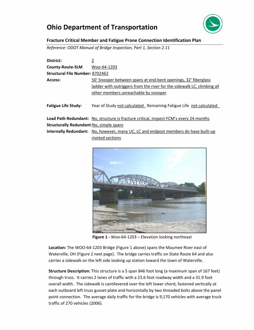
Ohio Department of Transportation
Fracture Critical Member and Fatigue Prone Connection Identification Plan
Reference: ODOT Manual of Bridge Inspection, Part 1, Section 2.11 District: 2 County‐Route‐SLM Woo‐64‐1203 Structural File Number: 8702462 Access: 50’ Snooper between spans at end‐bent openings, 32’ fiberglass
ladder with outriggers from the river for the sidewalk LC, climbing all other members unreachable by snooper
Fatigue Life Study: Year of Study not calculated_ Remaining Fatigue Life not calculated_ Load Path Redundant: No, structure is fracture critical, inspect FCM’s every 24 months Structurally Redundant:No, simple spans Internally Redundant: No, however, many UC, LC and endpost members do have built‐up
riveted sections
Figure 1 ‐ Woo‐64‐1203 – Elevation looking northeast
Location: The WOO‐64‐1203 Bridge (Figure 1 above) spans the Maumee River east of Waterville, OH (Figure 2 next page). The bridge carries traffic on State Route 64 and also carries a sidewalk on the left side looking up station toward the town of Waterville.
Structure Description: This structure is a 5 span 846 foot long (a maximum span of 167 feet) through truss. It carries 2 lanes of traffic with a 23.6 foot roadway width and a 31.9 foot overall width. The sidewalk is cantilevered over the left lower chord, fastened vertically at each outboard left truss gusset‐plate and horizontally by two threaded bolts above the panel point connection. The average daily traffic for the bridge is 9,170 vehicles with average truck traffic of 270 vehicles (2006).

Figure 2 – Woo‐64‐1203; East end of Waterville in ODOT District 2 on the Wood and Lucas County border over the Maumee River
Figure 3 – Highlighted red Floorbeams, Lowerchords and Diagonal tension members are fracture critical; symmetrical all spans
All floor beams are fracture critical members
Lower chords and diagonals are fracture critical members, Hip verticals receive tension under live load

*Blank cells are for inspectors to add FPD’s, retrofits or fatigue crack locations in future inspections
Fatigue Prone Details
Category reference: AASHTO LRFD Bridge Design Specs Table 6.6.1.2.3‐1
Photo Reference (photos on
following pages)
Category
(E, E’ or R for Retrofit)
Distribution Description
Appendix G
Scour Critical Susceptibility Plan of Action (POA)
Template

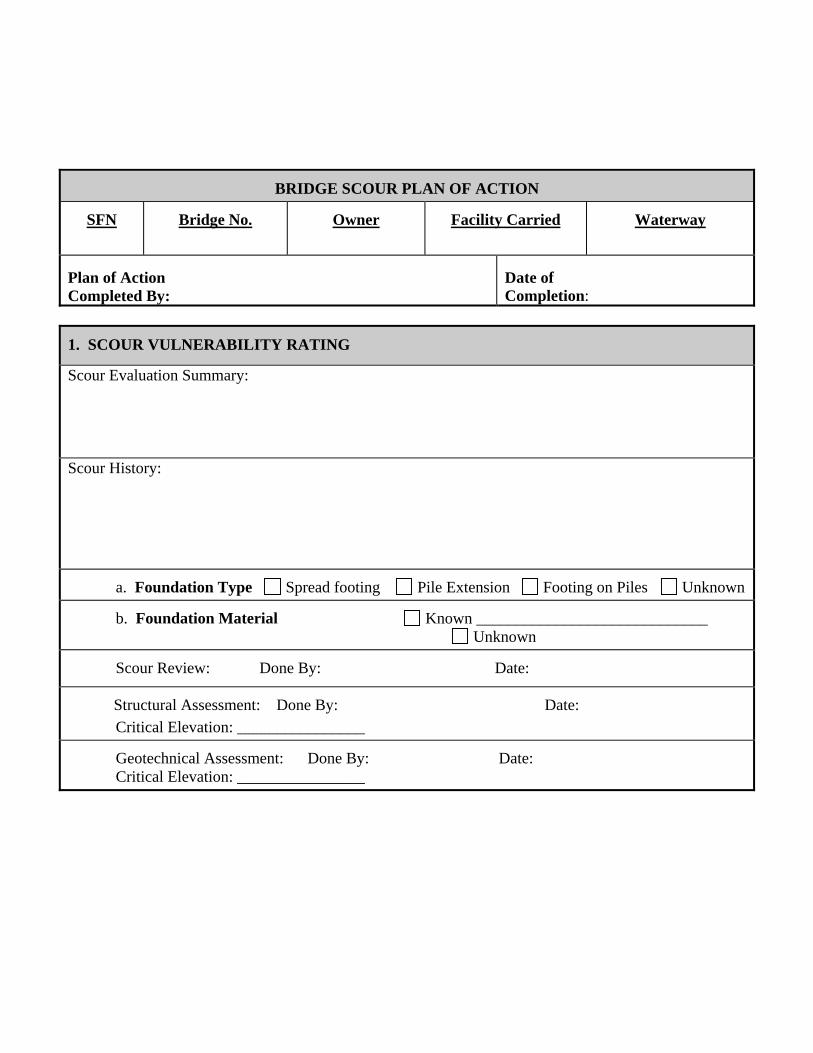
BRIDGE SCOUR PLAN OF ACTION
SFN
Bridge No.
Owner
Facility Carried
Waterway
Plan of Action Completed By:
Date of Completion:
1. SCOUR VULNERABILITY RATING
Scour Evaluation Summary: Scour History:
a. Foundation Type Spread footing Pile Extension Footing on Piles Unknown
b. Foundation Material Known _____________________________ Unknown
Scour Review: Done By: Date: Structural Assessment: Done By: Date: Critical Elevation: ________________
Geotechnical Assessment: Done By: Date: Critical Elevation: ________________

3. SCOUR COUNTERMEASURE RECOMMENDATION Completed Countermeasures: Proposed Countermeasures:
Countermeasures Not Required. (Please explain)
Install Scour Countermeasures (See 4 and 5) Estimated Cost Riprap with monitoring program $ Guide bank $ Spurs $ Relief bridge / Culvert $ Channel improvements $ Monitoring $ Monitoring device $ Check Dam $ Substructure Modification $ Bridge replacement $ Other __________________________________________ $
3. COUNTERMEASURE IMPLEMENTATION SCHEDULE
Countermeasure Implementation Project Type: Proposed Construction Project Lead Agency Maintenance Project Sale Date: Other scheduling information:
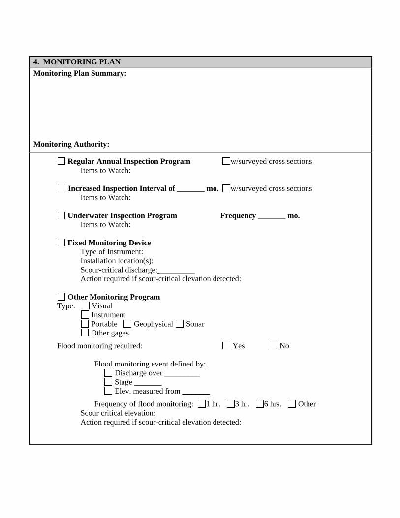
4. MONITORING PLAN Monitoring Plan Summary:
Monitoring Authority:
Regular Annual Inspection Program w/surveyed cross sections Items to Watch:
Increased Inspection Interval of _______ mo. w/surveyed cross sections Items to Watch:
Underwater Inspection Program Frequency _______ mo. Items to Watch:
Fixed Monitoring Device Type of Instrument: Installation location(s): Scour-critical discharge: _________ Action required if scour-critical elevation detected:
Other Monitoring Program Type: Visual Instrument Portable Geophysical Sonar Other gages
Flood monitoring required: Yes No Flood monitoring event defined by: Discharge over _________ Stage _______
Elev. measured from _______
Frequency of flood monitoring: 1 hr. 3 hr. 6 hrs. Other Scour critical elevation:
Action required if scour-critical elevation detected:

5. BRIDGE CLOSURE PLAN
Closure Plan Summary
Scour Monitoring Criteria for Consideration of Bridge Closure:
Water surface elevation reaches Overtopping road or structure Scour Measurement Results / Monitoring Device Loss of Riprap Observed amount of Settlement Loss of Road Embankment
Debris Accumulation Other Person / Area Responsible for Closure: Contact People (Name & Phone No.):

6. DETOUR ROUTE Detour route description (route number, from - to, etc.) – attach map. Detour length Signs required for closure: Bridges on Detour Route:
Structural File Number
Bridge Number Waterway Load Rating
Other restrictions


Appendix H
Scour Critical Assessment Checklist

Scour Critical Susceptibility Assessment
Bridge Number
SFN
Feature Intersected
Assessment Team Members
1) Condition Rating History A) Channel ‐ Year
51. Alignment 52. Protection 53. Waterway Adequacy 54. Channel Summary
B) Culvert/Approach ‐Year 59. Embankment 48. Scour
C) Substructure ‐ Year 39. Fenders and Dolphins 40. Scour 41. Slope Protection 42. Substructure Sum.
2) Overtopping Y NA) Inventory ‐ Waterway Adequacy Rating ‐ Item 88: _________________________________B) History of Overtopping
Remote ‐ Greater than 100 yearsSlight ‐ Between 11 and 100 yearsOccasional ‐ Between 3 and 10 yearsFrequent ‐ Within 3 years
Y N1) Low Risk
A) Is the structure a culvert (excluding 3‐sided culverts)?B) Are all abutments and pier footings keyed into rock?C) Are all drilled shafts embedded into rock?
2) Scour SusceptibleA) Is there a scour or a history of scour problems?B) Are the foundations spread footing or unknown foundations?C) Is the structure nonredundant, simple span or 3‐sided culvert?D) Does the structure have an inadequate waterway openning or design that collects ice and/or debris?E) Is the streambed experiencing active degradation or aggredation?F) Is the streambed experiencing active lateral movement or bank erosion?G) Do the banks have steep slopes or is there high stream velocity?H) Are there in ‐stream mining operations in the vicinity of the structure?I) Does the structure have a history of flood damage to the roadway or structure?J) Does the structure cross near stream confluences?K) Does the structure cross sharp bends?L) Is the structure located in alluvial fans?
OFFICE ASSESSMENT
Office Check ‐ Step 1/6 ‐ Performed by:
Screening ‐ Step 2/6 ‐ Performed by:
Structure Information

Scour Critical Susceptibility Assessment
FIELD ASSESSMENTUpstream Condition ‐ Step 3/6 ‐ Performed by:
Y NA) Banks
1) Stable:Natural vegetation, trees, bank stabilization measures such as riprap, paving,gabions, channel stabilization measures such as dikes and jetties
2) Unstable:Bank sloughing, undermining, evidence of lateral movement, damage to streamstabilization measures, etc.
B) Main Channel1) Clear and open with good approach flow conditions?2) Does channel meander or is it braided with main channel at an angle to the
orientation of the bridge?3) Existence of islands, bars, debris, cattle guards and fences that may affect flow?4) Aggrading or degrading of streambed?5) Evidence of movement of channel with respect to the bridge?
C) Floodplain1) Evidence of significant flow on floodplain2) Floodplain flow patterns ‐ does flow overtop road and/or return to main channel?3) Is there hydraulic adequacy of the relief bridge (if relief bridges are
obstructed, they will affect flow patterns at the main channel bridge)?4) Is there floodplain development and any obstruction to flows approaching
the bridge and its approaches?5) Evidence of overtopping approach roads (debris, erosion of embankment slopes,
damage to riprap or pavement, etc)?
D) Debris1) Large amounts of debris obstructing or hung up on substructure.2) Small amounts of debris obstructing or hung up on substructure.3) No debris obstructing flow or hung up on substructure.
Conditions at Bridge ‐ Step 4/6 ‐ Performed by:
Y NA) Substructure
1) Are there evidence of scour and/or undermining of abutments or pier footings?2) Is the main current attacking piers or abutments at an angle (apprx angle _______)?3) Has riprap been removed and replaced by bed‐load material4) Can displaced riprap be seen below the bridge?5) Are guidebanks in place?
Are guidebanks in good working order?Have scour or erosion damaged the guidebanks?
6) Is there evidence of scour and erosion of streambeds and banks, especially adjacent to piers and abutments?
7) Has the stream cross section changed since the last measurement?In what way?
B) Superstructure1) Is there evidence of overtopping (debris in cross frames, railing anchors etc)?3) Is the superstructure tied down to the substructure to prevent displacement
during floods?5) Is the superstructure a simple span configuration and/or nonredundant load path?

Scour Critical Susceptibility Assessment
FIELD ASSESSMENT (cont.)Downstream Condition ‐ Step 5/6 ‐ Performed by:
Y NA) Banks
1) Stable:Natural vegetation, trees, bank stabilization measures such as riprap, paving,gabions, channel stabilization measures such as dikes and jetties
2) Unstable:Bank sloughing, undermining, evidence of lateral movement, damage to streamstabilization measures, etc.
B) Main Channel1) Clear and open with good "getaway" conditions?2) Does channel meander?3) Is the channel braided with bends?4) Does the channel have islands or bars?5) Are there cattle guards or fences that restrict the flow?6) Aggrading or degrading stream bed?7) Evidence of movement of channel with respect to the bridge?
C) Floodplain1) Clear and open so that contracted flow at bridge will return smoothly to
the floodplain2) Is the floodplain restricted by dikes, developed trees, debris or other obstructions?3) Evidence of scour and erosion due to downstream turbulence?
CONCLUSION ‐ Step 6/6 ‐ Performed by: Y N1) Field Review Completed 2) SCOUR CRITICAL SUSCEPTIBILITY ‐ ITEM #74 ‐ Assessment with Field Review
A) Recommend one of the following codes according to this Assessment
6 ‐ Not Yet Evaluated (the purpose of this assessment is to remove this coding)
T ‐ Low Risk ‐ Not yet evaluated, bridge over Tidal Waters
9 ‐ Low Risk ‐ Stable; Bridge, including piles, are well above flood elevations
8 ‐ Low Risk ‐ Stable; scour is above top of footing and/or on rock that will resist scour throughout life
7 ‐ Low Risk ‐ Stable; Scour POA Countermeasures implemented
5 ‐ Low Risk ‐ Stable; scour within limits of known foundation
4 ‐ Low Risk ‐ Stable; field review found exposed foundations where action is required
U ‐ High Risk ‐ Unknown foundation ‐ develop POA
3 ‐ High Risk ‐ Unstable; field review found undermining ‐ develop POA
2 ‐ High Risk ‐ Unstable; extensive scour at bridge foundations ‐ develop POA, revise Scour Rating
1 ‐ Higher Risk ‐ Unstable; failure imminent, close bridge ‐ develop POA
0 ‐ Highest Risk ‐ Unstable; bridge has failed ‐ develop POA
Follow Up:Update Item #74 in BMSAssessment placed in the Bridge File

Appendix I
Cross Channel Profile Measurements

Cross Channel Profile Measurements Ohio Department of Transportation
Profile measurements may be used with photographs, rating histories and inspections in order to effectively and quantitatively monitor a stream, scour or countermeasures underneath structure. Take and record channel profile measurement to monitor the channel’s horizontal and vertical movement over time, identify size and depth of scour holes and monitor flow line. They must be compared with past inspections in order to monitor change. Detailed channel measurements are more important when Item 74 Scour Critical Susceptibility is 5 or less. Monitoring is considered a countermeasure because it can provide an early warning that allows timely closure of structure especially during a flood event. However, monitoring alone does not make the bridge itself safe from scour. Most often measurements are taken on the upstream side of the channel or on the same side as the last inspection. However measurements should be taken on the side that exhibits the most scour, degradation or other channel properties that may cause distress to the foundation units. For longer structures the profile may begin at an intermediate substructure unit for approach spans at the discretion of the inspector and multiple sheets may be used where more than 15 points are needed (see the attached “Channel Profile Measurements” form).
Figure No. 1: Bridge schematic showing typical locations for channel profile measurements (FHWA, “Stream Instability, Bridge Scour and Countermeasures; A Field Guide for Bridge Inspectors”, 2009) Enter flowline characteristics that could directly affect the substructure stability. Measure horizontal distances beginning from the rear abutment and take readings working forward. Measurements may be taken from above on the bridge deck or underneath the structure. A straightforward method from above may include the following:
1. Use a wheel and walk upstation (upstream or downstream side) and spray paint on the wearing surface ¼-span points and points that could change over time (slope grade changes, edges of water, maximum water depth, edges and highpoints of debris fields etc)
2. Go back at the paint marks and drop the loose end of a 100’-tape attached to a rope supporting a 5-10-lb weight until the weight hits the point below
3. Measure that distance at the top of the bridge rail and record it on the “Cross Channel Profile Measurements” Form
4. For each measurement subtract the vertical distance between the top of the bridge rail (or the location the distance was read) from the underside of the superstructure
From below
1. The inspector records from underneath with a laser point on the upstream or downstream side 2. Measure and record distances to the underside of the superstructure at the horizontal distances
using the laser pointer and a level 3. Locations include ¼-span points and points that could change over time (slope grade changes,
edges of water, maximum water depth, edges and highpoints of debris fields etc)

Cross Channel Profile Measurements Ohio Department of Transportation
Date: Bridge ID:
Bridge Location: Circle: Upstream or Downstream
The feature from which the measurements are taken (Curb, Top of Railing): The distance between the underside of the superstructure and the reference feature labeled above: ft.
Msmt Span Horizontal
Distance from Rear (ft)
Object Measured (abutment, pier, slope change, flowline, 1/4
span, 1/2, 3/4 etc.)
Vertical or Profile
Measurement (ft)
Comments
1
2
3
4
5
6
7
8
9
10
11
12
13
14
15


Appendix J
Quality Assurance Review (QAR) Form
1
Quality Assurance Review Bridge Inspection Program
The scope of this review is to evaluate the agency’s bridge inspection program based upon The Ohio Revised Code, the ODOT Manual of Bridge Inspection (MBI), and the National Bridge Inspection Standards (NBIS). This includes the following checklist, interviews with staff members responsible for the inspection program, review of files and documentation, and field inspection of bridges. Note: the inspection program includes inventory, maintenance and load rating in addition to the field inspections. Instructions for completing form: Please fill out checklist prior to scheduled review. Brief answers are desired; fill the items out to the best of your ability. Agency Reviewed:__________________________________________ Checklist completed by: _______________________Date:__________
I. MAINTENANCE, REHABILITATION AND REPLACEMENT PROGRAM A. NUMBER OF BRIDGES WITH MAINTENANCE RESPONSIBILITY
1. Greater than 20’ long (NBIS length 23CFR 650c) ________________
2. Bridges >= 10’ and <= 20' long ________________ B. PROCEDURES AND BUDGET
1. Contract repairs and replacement - List typical work items
- List approximate annual budget - Are Fed Funds used?
- Are Credit Bridge funds used?
2. In-house repairs and replacements - List typical work items - List approximate annual budget
- List staffing availability
3. How are projects identified and selected?
4. How are plans developed for emergency repairs?

2
5. Who does the work of emergency repairs?
6. How is repair work documented? (i.e. work record, time card)
7. Who is empowered to order emergency road closures and how is it done?
II. INSPECTION PROGRAM A. NUMBER OF BRIDGES WITH INSPECTION RESPONSIBILITY
1. Greater than 20’ long (NBIS length, ORC 5501.47, 5543.20)
2. Between 10’ and 20' long (including 10’ & 20’) (ORC 5501.47, 5543.20) B. STAFFING
1. Name of individual who is the Program Manager (makes FINAL DECISION)
a. List qualifications/experience (bridge inspection experience)
b. List courses attended (& approx dates)
2. Name of individual in charge of bridge inspection unit (Reviewer)
a. List qualifications/experience (bridge inspection experience)
b. List courses attended (& approx dates)
3. Team Leader - individual in charge of bridge inspection team (INSPECTED BY) a. List qualifications/experience (bridge inspection experience)
b. List courses completed (& approx. dates)
c. Indicate the percentage of time spent on the listed duties in the previous year
%TIME _____ Bridge/Culvert inspection _____ Bridge Design/Plan prep _____ Bridge Construction _____ Bridge Maintenance
_____ Overload/Superload _____ Surveying _____ Other - _____100%

3
4. Team Leader - individual in charge of bridge inspection team (INSPECTED BY) a. List qualifications/experience (bridge inspection experience)
b. List courses completed (& approx. dates)
c. Indicate the percentage of time spent on the listed duties in the previous year
%TIME _____ Bridge/Culvert inspection _____ Bridge Design/Plan prep _____ Bridge Construction _____ Bridge Maintenance
_____ Overload/Superload _____ Surveying _____ Other - _____100%
5. Team Leader - individual in charge of bridge inspection team (INSPECTED BY)
a. List qualifications/experience (bridge inspection experience)
b. List courses completed (& approx. dates)
c. Indicate the percentage of time spent on the listed duties in the previous year
%TIME _____ Bridge/Culvert inspection _____ Bridge Design/Plan prep _____ Bridge Construction _____ Bridge Maintenance
_____ Overload/Superload _____ Surveying _____ Other - _____100%
6. Team Leader - individual in charge of bridge inspection team (INSPECTED BY)
a. List qualifications/experience (bridge inspection experience)
b. List courses completed (& approx. dates)
c. Indicate the percentage of time spent on the listed duties in the previous year
%TIME _____ Bridge/Culvert inspection _____ Bridge Design/Plan prep _____ Bridge Construction _____ Bridge Maintenance
_____ Overload/Superload _____ Surveying _____ Other - _____100%

4
7. Team Member of bridge inspection team ( Include information for each additional team member – copy and paste as needed)
a. List name/qualifications/experience (bridge inspection experience)
b. List courses completed (& approx. dates) c. Indicate the percentage of time spent on the listed duties in the previous year %TIME _____ Bridge/Culvert inspection _____ Bridge Design/Plan prep _____ Bridge Construction _____ Bridge Maintenance
_____ Overload/Superload _____ Surveying _____ Other - _____100%
8. Team Member of bridge inspection team ( Include information for each additional
team member – copy and paste as needed)
a. List name/qualifications/experience (bridge inspection experience)
b. List courses completed (& approx. dates) c. Indicate the percentage of time spent on the listed duties in the previous year %TIME _____ Bridge/Culvert inspection _____ Bridge Design/Plan prep _____ Bridge Construction _____ Bridge Maintenance
9. Team Member of bridge inspection team ( Include information for each additional team member – copy and paste as needed)
a. List name/qualifications/experience (bridge inspection experience)
b. List courses completed (& approx. dates) c. Indicate the percentage of time spent on the listed duties in the previous year %TIME _____ Bridge/Culvert inspection _____ Bridge Design/Plan prep _____ Bridge Construction _____ Bridge Maintenance

5
C. INSPECTION EQUIPMENT
1. Type of vehicle used for inspections
2. What typical inspection equipment does the inspection team normally carry with them to the inspection site?
Yes/No Extension Ladder ___ what length? ___ 6’ Folding Rule ___ 100' Fiberglass Tape ___ Geologist Hammer ___ Inspection Mirror ___ Flashlight ___ Thermometer ___ Plumb Bob ___ Camera ___ 2'-0" Level ___ Brush Hook/Axe ___ Boat ___
First Aid Kit ___ Wire Brush ___ Calipers ___ Shovel ___ Screw Driver ___ Pliers ___ Wrenches ___ Sounding Chains ___ Hip Boots and Waders ___ Paint Stick/Crayon ___ Scraper ___ Probing Rod ___ Vertical Clearance Rod ___
3. List types of NDT methods used ( IE. dye penetrant, magnetic particle,
ultrasound) 4. How is usage determined?
5. List additional items
6. What equipment does your team have available for "hands on" access to FCM
bridge members?
7. Use of equipment a. How many bridges need a snooper? b. How many bridges is it used on? c. How often?
D. INSPECTION PROCEDURES
1. Approximately how many inspections were made during last calendar year?
2. Approximately how many inspections are scheduled for the current calendar year?

6
3. Average number of inspections per day
4. Approximately how long (hours) does it take to inspect average sized structures
a. Beam/Girder b. Slab c. Truss (pony/through/deck) d. Culvert
5. Are previous inspection reports available at site for review? (Yes ___ No ___ )
Are bridge inspections recorded in field on paper or electronically? Please describe: Are Bridge comments recorded? (Yes ___ No ___ ) Are bridge comments brought to the bridge? (Yes ___ No ___ )
6. Are the bridge plans carried to the bridge site for review if necessary or are they
readily available for review in the bridge office?
a. Bridge site (Yes ___ No ___ ) b. Bridge office (Yes ___ No ___ )
7. Who determines the need for an inspection frequency greater than once
annually?
8. List bridges requiring inspection more frequently than one year intervals (SPECIAL INSPECTIONS)
9. Does the inspection team believe it has enough time to do the job?
(Yes ___ No ___ )
10. What kinds of quality assurance checks are made of the inspection process? E. SCOUR CRITICAL BRIDGES (Guidance in ODOT Manual of Bridge Inspection)
1. How many bridges are considered scour susceptible? (TOS OVER WATER)
2. How many bridges are inspected by probing? (INV AND INSP)
3. How many structures are Scour Critical (item 74 - 3, 2, 1 or 0)?

7
4. Are Plans of Action (POA) complete and implemented for all bridges coded “Scour Critical”?
5. How many structures are coded 6 on item 74 Scour Critical?
6. How are scour evaluations performed?
7. Who determines the need for diving inspections and by what criteria?
F. INVENTORY
1. What kinds of inventory quality assurance checks are performed?
2. How often is the inventory checked for needed updates?
3. How is the inventory data input into the system?
4. When is the updated inventory data forwarded to ODOT?
5. NBIS requires that the inspecting organization maintain master lists of the following: (Provide a list of these bridges)
a. Bridges that contain fracture critical members, including the location and description of such members on the bridge and the inspection procedures of such members (Each individual FCM member on each FCM bridge must be clearly identified in the bridge file) (Where a FCM Identification Plan exists then look for remaining fatigue life)
b. Bridges requiring underwater inspections
c. Bridges with unique or special features (i.e., pin & hanger, draw,
suspension)
Note: An examination of the files will be performed during the review.
- Bridge Files - Scour Critical POA - Fracture Critical Plan

8
G. FOLLOW-UP PROCEDURES
1. Are new maintenance problems identified on the bridge inspection form? ( Y___N___ ) On another form? (Yes ___ No ___ )
2. How do the inspectors inform maintenance personnel of routine bridge
maintenance problems ( written, oral, other)?
3. Who do the inspectors notify when emergency repairs or critical findings are necessary (bridge section, maintenance, other)?
4. If a bridge requires emergency repairs, is this noted as part of the inspection
report or as a separate document?
5. Who checks proper placement of signs (load posting, clearance, speed restriction, narrow bridge etc.)?
H. LOAD ANALYSIS AND POSTING
1. Number of plans for existing bridges available for NBIS length bridges
2. Number of plans for non-NBIS bridges (>= 10’ and <= 20' long)
3. Number of bridges analyzed in accordance with the AASHTO Manual for Bridge Evaluation
4. By Whom
5. When
6. Methods used
7. When are bridges rerated and how do load raters keep up with overlays and
other changes?
8. Number of NBIS length bridges not load rated
9. List the NBIS length bridges considered “not ratable” including reason for being considered “not ratable”
10. Number of NBIS length bridges load posted
11. How determined (engineering judgment, analysis, mix)

9
12. List bridges closed due to condition rating (rough check)
13. List bridges rated less than 95% Ohio legal load and not physically load posted, and resolution
14. Number of NBIS bridges with Gusset Plates
15. Number of NBIS bridges with Gusset Plates analyzed.
I. RECOMMENDED PRACTICES This area of the report should list any innovative ideas that provide valuable support and process improvement for offices across the State. For example: It creates a safer work environment, deploys resources efficiently, maximizes available resources, is measurable etc.

10
J. FIELD REVIEW
SFN County Route SLM Notes
1
2
3
4
5
6
7
8
9
10
11
12

11
QAR FEEDBACK To submit feedback electronically, go to: http://portal.dot.state.oh.us/Divisions/QualityHR/QualityAssuranceReviews/Lists/Feedback%20Form/AllItems.aspx QAR Site Visit Date___________________________
Review Location (district): _______________________
Office That Received QAR: _____________________
QAR Review Team: _____________________________ ______________________________________________ ______________________________________________ ______________________________________________
Person completing this form: (optional) ___________________________
Date this form completed:________________________
Strongly
Agree Agree
Neutral
Disagree
Strongly Disagree
Not Applicable
1. The QAR concentrated on legal or otherwise regulatory requirements.
SA A N D SD NA
2. Policies & checklists were communicated in advance of the QAR visit.
SA A N D SD NA
3. The QAR team provided timely notification of the QAR visit. SA A N D SD NA
4. Discussions with the QAR review team were open and constructive.
SA A N D SD NA
5. The issues in the QAR report were fairly presented. SA A N D SD NA
6. Noncompliance issues were addressed on Noncompliance Action Plan
SA A N D SD NA
Are there any areas of the QAR process that can be improved? __________________________________________________________________________________________________________________________________________________________________________________________________________________________________ Please provide comments to explain your responses or provide any additional feedback or suggestions that may help to improve the QAR content or process. _______________________________________________________________________________________________________________________________________________________________________________________________________________________________________________________________________________________________________________
FOR ODOT INTERNAL QAR’s PLEASE FORWARD COMPLETED FORM TO: ODOT STATEWIDE QAR COORDINATOR DIVISION OF QUALITY & HUMAN RESOURCES, CENTRAL OFFICE

Appendix K
Critical Finding Report

g p
164
CRITICAL FINDINGS REPORT PURPOSE: The National Bridge Inspection Standards (23 CFR 650 subpart C) states critical findings are to be documented and addressed in a timely manner. This documentation is to do be completed upon the finding of a critical bridge deficiency. Date: Page of Owner: Structure File Number: Bridge Number: Inspection Agency: Description of critical findings: Immediate action taken to ensure safety of traveling public Current plan of action for the bridge
Pictures attached

Appendix L
Pin and Hanger
Detailed Inspection Form

Bridge - - InspectionDate(s)
Access
Hanger/Hinge
TemperatureBeams labeled left to right looking up station.
1
2
3
4
5
6
7
8
9
Rte. SLM
hBEAM j v r (section loss, floating, abrasion, bowing)
Inspector(s)
COMMENTSp e t
PIN AND HANGERDETAILED INSPECTION FORM
Co.
9
10
11
12
j
Values are in inches:
e h-horizontal at bottom of flange
j-joint b/w armor at beam;longitudinal w/traffic
ForwardBeam v-vertical (+) value where fwd. beam
is above, (-)belowRearBeam e r-rotation transverse (+) value fwd.
beam right, (-) left
p p-pins (+) value top pin fwd. ofvertical, (-) rear
he-hanger ends from center of pin
t-any thickness measurements (labelr locations on drawing)
v
Appendix M
Movable Bearing
Detailed Inspection Form
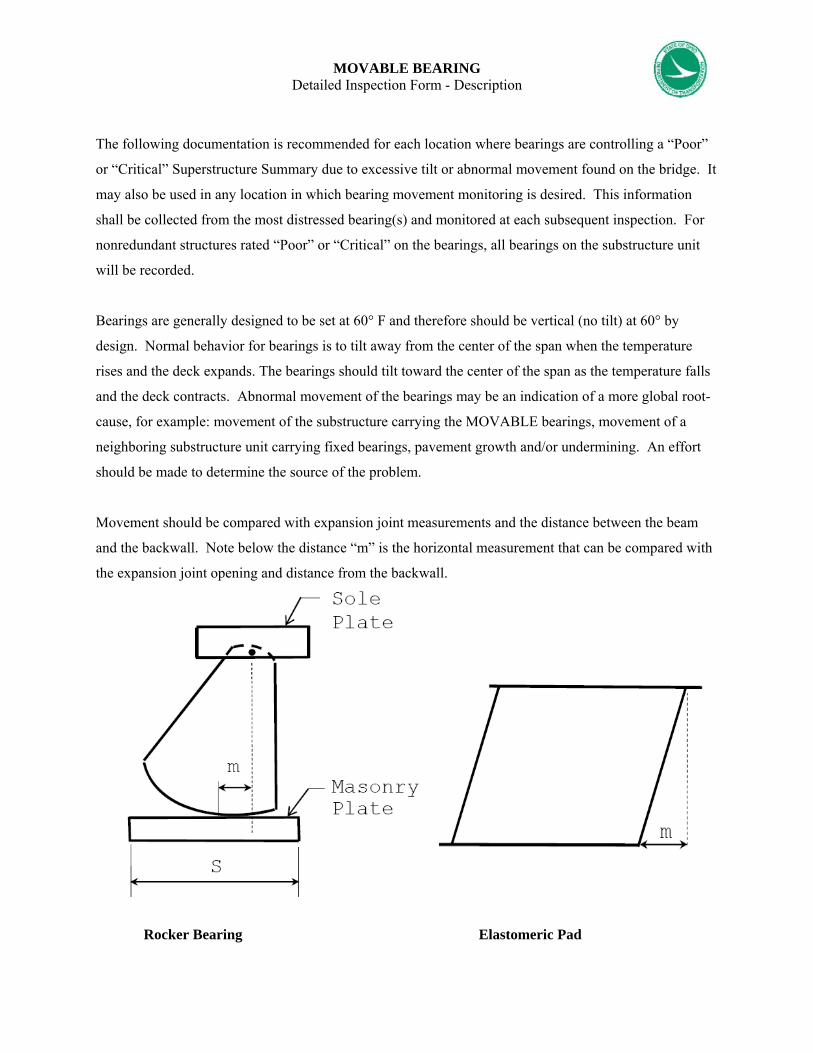
MOVABLE BEARING Detailed Inspection Form - Description
The following documentation is recommended for each location where bearings are controlling a “Poor”
or “Critical” Superstructure Summary due to excessive tilt or abnormal movement found on the bridge. It
may also be used in any location in which bearing movement monitoring is desired. This information
shall be collected from the most distressed bearing(s) and monitored at each subsequent inspection. For
nonredundant structures rated “Poor” or “Critical” on the bearings, all bearings on the substructure unit
will be recorded.
Bearings are generally designed to be set at 60° F and therefore should be vertical (no tilt) at 60° by
design. Normal behavior for bearings is to tilt away from the center of the span when the temperature
rises and the deck expands. The bearings should tilt toward the center of the span as the temperature falls
and the deck contracts. Abnormal movement of the bearings may be an indication of a more global root-
cause, for example: movement of the substructure carrying the MOVABLE bearings, movement of a
neighboring substructure unit carrying fixed bearings, pavement growth and/or undermining. An effort
should be made to determine the source of the problem.
Movement should be compared with expansion joint measurements and the distance between the beam
and the backwall. Note below the distance “m” is the horizontal measurement that can be compared with
the expansion joint opening and distance from the backwall.
Rocker Bearing Elastomeric Pad

MOVABLE BEARING INSPECTION FORM
Date Substructure Unit
Beam No.
Dim “A”
Dim “B”
Dim “C”
Dim “D”
Dim “X”
Angle “θ”
Dim “E”


Appendix N
Damage Inspection – 4SRC Funds &
Extent / Severity for Over-height Hits on Steel Beam
Superstructure Bridges

SAC 4SR7 emergency fund For State owned structures only, an emergency fund is available from Central Office to fund the
emergency repairs to damaged bridges. This new SAC 4SR7 emergency fund will alleviate the districts
from having to use District allocations to contract emergency repairs.
What Costs are Eligible for the Program:
1. 100% of the Contract Cost Only, including mobilization, traffic control and a hired consultant
for plans, if applicable. In house costs such as plan design, inspection costs or any other
labor costs are not eligible. This fund is intended to be used for damage to bridges caused by
accidents and cannot be used for normal guardrail hits or damage to a bridge as a result of
graffiti. Each request for use of the funds will be evaluated against the established guidelines.
Unique circumstances will be evaluated on a case by case basis.
2. The program will only cover the above costs if the repairs are completed within 12 months
from the accident date. The program manager will have the ability to provide an extension to
the 12 month requirement if there are extenuating circumstances.
If a bridge is already planned for replacement or major reconstruction within 3 years , it is not
eligible for this program.
Process to Report Damage:
1. Districts submit a bridge report to Office of Structures. The report should include:
Accident Patrol Report
Bridge Inspection Report
Critical Findings Report
Estimate of Damage – A template is available on the following pages for
inspectors to gather quantitative deficiencies on steel beam bridge-hits
Pictures
2. Office of Structures will forward the above documentation to the Office of Revenue and
Fiscal Reporting.

Ellis Programming:
1. Districts email program manager the following information when they are ready to request
approval to fund the project:
• Bridge Number
• Location
• Date of Accident
• Approximate Sell Date - Quarter and Year (should be within 12 months of
accident date)
• Estimate Amount
2. Program Manager will return email with approval or disapproval for use of the program
SAC based on the above criteria.
3. Upon approval by the Program Manager, the District can enter the project into Ellis.
Programming using the Bridge Damage SAC 4SR7. The District must then provide the PID#
to Rich and copy Stephanie and Lisa.
If a bridge is damaged during the course of an existing awarded construction project, the cost to
repair the damage should not be processed against established state/federal funding. The costs to
repair should follow the above process utilizing the SAC 4SR7.
Establishing an Accounts Receivable:
1. The Office of Fiscal Reporting will monitor the projects using the SAC 4SR7 and follow up
with the districts upon the project’s estimated completion date.
2. When the project is complete, within 45 days, the Districts will gather the cost breakdown
and forward to the Office of Revenue and Fiscal Reporting who will initiate a final invoice to
the insurance company and/or insured.
The documents needed should include the contract cost and any incurred ODOT costs (plan
design, inspection or other labor costs are NOT eligible). All costs should be itemized with
supporting documents including copies of paid invoices, project labor logs, or if a lump sum
bid such as heat straightening a copy of the bid. Each package should include a cover sheet

summarizing the costs with a grand total for billing. 2 copies of the costs packages are sent
to the program manager, Lisa Jones for billing.
3. The Office of Revenue and Fiscal Reporting will invoice all bridge damages.
NOTE:
If the above process is not followed and the district bills for bridge damages or the proper documents
are not received, then the district will be required to use their own budget for funding.
Revenue Source Supporting this Program:
1. The revenue collected from property damages, (Ex. guardrails, signs, etc.) is certified to the
Attorney General’s Office.
2. Any money collected from claimant or insurance companies for these projects.

Bridge Date
Time
Route On Inspectors:
Lanes Closed:
Contacted:
Route Under
Lanes Closed:
Y N
Damage Section
Beam No.Pier/Abut Reference
B C D E F1 F2 G JGrind Nicks and
Gouges
(ex. Owner, EMS, etc.)
Estimate of Damage
Pictures
Critical Findings Report
Bridge Inspection Report
Accident Patrol Report
Documents Attached:
Table No. 1 - Damaged Main Member to be Heat Straightened
Severity & Extent of Damage for Steel Beam Superstructure
Controlling Minimum Vertical Clearance (xx'-xx") with location and additional pertinent information
See Tables 1 and 2 below with attached dwgs.
DAMAGE INSPECTION
Over height Bridge Hit
Co - Rte - SLM
Between Beams Pier/Abut N ID 2D 3S 4S
N- Number of crossframes from abutment of pier referenced in
Notes:Table No. 2 - Damaged Secondary Member to be
replaced (i.e.. crossframe)

Use for Table 1
Use for Table 1 Use for Table 2
DAMAGE INSPECTIONOver height Bridge Hit (cont)
Severity/Extent of Damage for Steel Beam Superstructure
Remove according to Item 202-Portions of secondary members removed, as per plan, replace by matching existing detail, see GSD-1-96 for additional clarification
J = Length of epoxy injectionNegative G values are bent leftNegative F Values are bent downNegative E Values are bent left
Section A-A

Appendix O
Measurements of Corrugated Metal Culverts

Measurements of corrugated metal culverts The corrugated metal culvert barrel depends on the backfill or embankment to maintain its proper shape and stability. When the backfill does not provide the required support, the culvert will deflect, settle, or distort. Shape changes in the culvert therefore provide a direct indication of the adequacy and stability of the supporting soil envelope. By periodic observation and measurement of the culvert's shape, it is possible to verify the adequacy of the backfill. The design or theoretical cross- section of the culvert should be the standard against which field measurements and visual observations are compared. If the design cross section is unknown, a comparison can be made between the unloaded culvert ends and the loaded sections beneath the roadway or deep fills. This can often provide an indication of structure deflection or settlement. Symmetrical shape and uniform curvature around the perimeter are generally the critical factors. If the curvature around the structure becomes too flat, and/or the soil continues to yield under load, the culvert wall may not be able to carry the ring thrust without either buckling inward or deflecting excessively to the point of reverse curvature. Either of these events leads to partial or total failure. Corrugated metal pipes can change shape safely within reasonable limits as long as there is adequate exterior soil pressure to balance the ring compression. Therefore, size and shape measurements taken at any one time do not provide conclusive data on backfill instability even when there is significant deviation from the design shape. Current backfill stability cannot be reliably determined unless changes in shape are measured over time. It is therefore necessary to identify current or recent shape changes to reliably check backfill stability. Locations in sectional pipe can be referenced by using pipe joints as stations to establish the stationing of specific cross-sections. Stations should start with number 1 at the outlet and increase going upstream to the inlet. The location of points on a circular cross section can be referenced like hours on a clock. The clock should be oriented looking upstream. On structural plate corrugated metal culverts, points can be referenced to bolted circumferential and longitudinal seams. It is extremely important to tie down exact locations of measurement points. Unless the same point is checked on each inspection, changes cannot be accurately monitored. The inspection report must, therefore, include precise descriptions of reference point locations. It is safest to use the joints, seams, and plates as the reference grid for measurement points. Exact point locations can then be easily described in the report as well as physically marked on the structures. This guards against loss of paint or scribe marks and makes points easy to find or reestablish. All dimensions in structures should be measured to the inside crest of corrugation. When possible, measurement points on structural plate should be located at the center of a longitudinal seam. However, some measurement points are not on a seam. Visual observation of the shape should involve looking for flattening of the sides, peaking or flattening of the crown, or racking to one side. Form A-1 may be used to record measurements of corrugated metal culverts. Minimum measurements include the vertical distance from the crown to the invert and the horizontal distances from each side at its widest point to a vertical line from the highest point on the crown. These horizontal distances should be equal. When they differ by more than 10 inches or 5 percent of the span, whichever is less, racking has occurred and the curvature on the flatter side of the arch should be checked by recording chord and mid-ordinate measurements. Racking can occur when the rise checks with the design rise. When the rise is more than 5 percent less than the design rise, the curvature of the top arc should be checked.
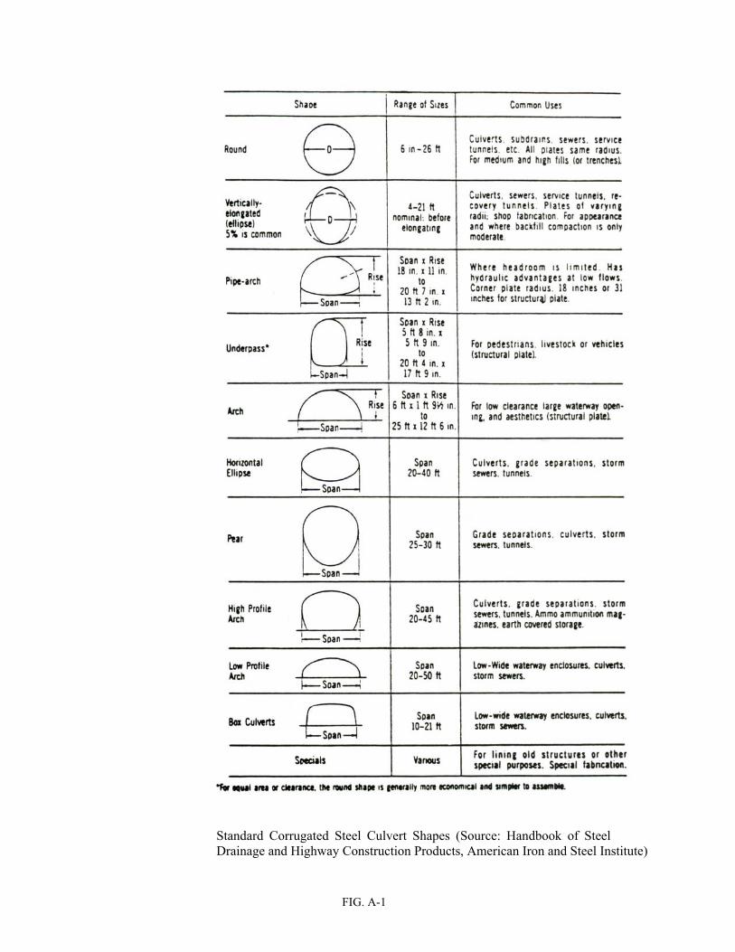
FIG. A-1
Standard Corrugated Steel Culvert Shapes (Source: Handbook of Steel Drainage and Highway Construction Products, American Iron and Steel Institute)


Appendix P
Glossary of Bridge Inspection Terms

G-1
GLOSSARY
A AASHTO - American Association of State Highway and Transportation Officials, name changed from AASHO (American Association of State Highway Officials) in 1973 American Association of State Highway and Transportation Officials (AASHTO) Manual - “Manual for Condition Evaluation of Bridges,” second edition, published by the American Association of State Highway and Transportation Officials (incorporated by reference into 23 CFR 650)
abrasion - wearing or grinding away of material by friction; usually caused by sand, gravel, or stones, carried by wind or water absorption - the process of a liquid being taken into a permeable solid (e.g., the wetting of concrete) abutment - part of bridge substructure at either end of bridge which transfers loads from superstructure to foundation and provides lateral support for the approach roadway embankment ADT - Average Daily Traffic ADTT - Average Daily Truck Traffic admixture - an ingredient added to concrete other than cement, aggregate or water (e.g., air entraining agent) aggradation - progressive raising of a streambed by deposition of sediment aggregate - hard inert material such as sand, gravel, or crushed rock that may be combined with a cementing material to form mortar or concrete air entrainment - the addition of air into a concrete mixture in order to increase the durability and resist thermal forces alignment - the relative horizontal and vertical positioning between components, such as the bridge and its approaches alignment bearing - a bearing embedded in a bridge seat to prevent lateral movements (see BEARING) alligator cracking - cracks initiated by inadequate base support or drainage that form on the surface of a road in adjacent, rectangular shapes (like the skin of an alligator) alloy - two or more metals, or metal and non-metal, intimately combined, usually by dissolving together in a molten state to form a new base metal anchorage - the complete assemblage of members and parts, embedded in concrete, rock or other fixed material, designed to hold a portion of a structure in correct position

G-2
anchor bolt - a metal rod or bar commonly threaded and fitted with a nut and washer at one end only, used to secure in a fixed position upon the substructure the bearings of a bridge, the base of a column, a pedestal, shoe, or other member of a structure anchor span - the span that counterbalances and holds in equilibrium the cantilevered portion of an adjacent span; also called the back span; see CANTILEVER BEAM, GIRDER, or TRUSS angle - a basic member shape, usually steel, in the form of an "L" anisotropy - the property of certain materials, such as crystals, that exhibits different strengths in different directions anode - the positively charged pole of a corrosion cell at which oxidation occurs anti-friction bearing - a ball or roller-type bearing; a bearing that reduces transfer of horizontal loads between components appraisal rating - a judgment of a bridge component's adequacy in comparison to current standards approach - the part of the roadway immediately before and after the bridge structure approach pavement - an approach which has a cross section that is either the same as or slightly wider than the bridge deck width approach slab - a reinforced concrete slab placed on the approach embankment adjacent to and usually resting upon the abutment back wall; the function of the approach slab is to carry wheel loads on the approaches directly to the abutment, thereby transitioning any approach roadway misalignment due to approach embankment settlement appurtenance - an element that contributes to the general functionality of the bridge site (e.g., lighting, signing) apron - a form of scour (erosion) protection consisting of timber, concrete, riprap, paving, or other construction material placed adjacent to abutments and piers to prevent undermining arch - a curved structure element primarily in compression that transfers vertical loads through inclined reactions to its end supports arch barrel - a single arch member that extends the width of the structure arch rib - the main support element used in open spandrel arch construction; also known as arch ring armor - a secondary steel member installed to protect a vulnerable part of another member, e.g., steel angles placed over the edges of a joint; also scour protection such as rip rap as-built plans - plans made after the construction of a project, showing all field changes to the final design plans (i.e.. showing how the bridge was actually built)

G-3
asphalt - a brown to black bituminous substance that is found in natural beds and is also obtained as a residue in petroleum refining and that consists chiefly of hydrocarbons; an asphaltic composition used for pavements and as a waterproof cement ASTM - American Society for Testing and Materials auger - a drill with a spiral channel used for boring axial - in line with the longitudinal axis of a member axle load - the load borne by one axle of a traffic vehicle, a movable bridge, or other motive equipment or device and transmitted through a wheel or wheels
B back - see EXTRADOS backfill - material, usually soil or coarse aggregate, used to fill the unoccupied portion of a substructure excavation such as behind an abutment stem and backwall backstay - cable or chain attached at the top of a tower and extending to and secured upon the anchorage to resist overturning stresses exerted upon the tower by a suspended span backwall - the topmost portion of an abutment above the elevation of the bridge seat, functioning primarily as a retaining wall with a live load surcharge; it may serve also as a support for the extreme end of the bridge deck and the approach slab backwater - the back up of water in a stream due to a downstream obstruction or constriction bank - sloped sides of a waterway channel or approach roadway, short for embankment bascule bridge - a bridge over a waterway with one or two leaves which rotate from a horizontal to a near-vertical position, providing unlimited overhead clearance base course - a layer of compacted material found just below the wearing course that supports the pavement base metal - the surface metal of a steel element to be incorporated in a welded joint; also known as structure metal, parent metal base plate - steel plate, whether cast, rolled or forged, connected to a column, bearing or other member to transmit and distribute its load to the substructure batten plate - a plate with two or more fasteners at each end used in lieu of lacing to tie together the shapes comprising a built-up member

G-4
batter - the inclination of a surface in relation to a horizontal or a vertical plane; commonly designated on bridge detail plans as a ratio (e.g., 1:3, H:V); see RAKE battered pile - a pile driven in an inclined position to resist horizontal forces as well as vertical forces bay - the area of a bridge floor system between adjacent multi-beams or between adjacent floor beams beam - a linear structural member designed to span from one support to another and support vertical loads bearing - a support element transferring loads from superstructure to substructure while permitting limited movement capability bearing capacity - the load per unit area which a structural material, rock, or soil can safely carry bearing failure - crushing of material under extreme compressive load bearing pile - a pile which provides support through the tip (or lower end) of the pile bearing plate - a steel plate, which transfers loads from the superstructure to the substructure bearing pressure - the bearing load divided by the area to which it is applied bearing seat - a prepared horizontal surface at or near the top of a substructure unit upon which the bearings are placed bearing stiffener - a vertical web stiffener at the bearing location bearing stress - see BEARING PRESSURE bedding - the soil or backfill material used to support pipe culverts bedrock - the undisturbed rock layer below the surface soil bench mark - an established reference point with known elevation and coordinates, used to document dimensions, elevations or position movement bending moment - the internal force within a beam resulting from transverse loading bent - a substructure unit made up of two or more column or column-like members connected at their top-most ends by a cap, strut, or other member holding them in their correct positions berm - the line that defines the location where the top surface of an approach embankment or causeway is intersected by the surface of the side slope beveled washer - a wedge-shaped washer used in connections incorporating members with sloped flange legs, e.g., channels and S-beams bitumen - a black sticky mixture of hydrocarbons obtained from natural deposits or from distilling petroleum;

G‐5
tar
bituminous concrete - a mixture of aggregate and liquid asphalt or bitumen, which is compacted into a dense mass
blanket - a streambed protection against scour placed adjacent to abutments and piers
BMS - Bridge Management System
bolt - a mechanical fastener with machine threads at one end to receive a nut, and an integral head at the other end
bolster - a block-like member used to support a bearing on top of a pier cap or abutment bridge seat; see
PEDESTAL
bond - in reinforced concrete, the grip of the concrete on the reinforcing bars, which prevents slippage of the bars relative to the concrete mass
bond stress - a term commonly applied in reinforced concrete construction to the stress developed by a force tending to produce movement or slippage at the interface between the concrete and the reinforcement bars
bowstring truss - a general term applied to a truss of any type having a polygonal arrangement of its top chord members conforming to or nearly conforming to the arrangement required for a parabolic truss; a truss with a curved top chord
box beam - a hollow structural beam with a square, rectangular, or trapezoidal cross-section that supports
vertical loads and provides torsional rigidity
box culvert - a culvert of rectangular or square cross-section
box girder - a hollow, rectangular or trapezoidal shaped girder, a primary member along the longitudinal axis of the bridge, which provides good torsional rigidity
bracing - a system of secondary members that maintains the geometric configuration of primary members
bracket - a projecting support fixed upon two intersecting members to strengthen and provide rigidity to the connection
breastwall - the portion of an abutment between the wings and beneath the bridge seat; the breast wall
supports the superstructure loads, and retains the approach fill; see STEM
bridge - a structure including supports erected over a depression or an obstruction, such as water, highway, or railway, and having a track or passageway for carrying traffic or other moving loads, and having an opening measured along the center of the roadway of greater than or equal to 10 feet between undercopings of abutments or spring lines of arches, or extreme ends of openings for multiple boxes; it may also include multiple pipes, where the clear distance between openings is less than half of the smaller contiguous opening
bridge deficiency - a defect in a bridge component or member that makes the bridge less capable or less

G-6
desirable for use
bridge inspection experience - active participation in bridge inspections in accordance with the NBIS, in either a field inspection, supervisory, or management role. A combination of bridge design, bridge maintenance, bridge construction and bridge inspection experience, with the predominant amount in bridge inspection, is acceptable.
bridge inspection refresher training - the National Highway Institute “Bridge Inspection Refresher Training Course” 1 or other State, local, or federally developed instruction aimed to improve quality of inspections, introduce new techniques, and maintain the consistency of the inspection program. 1 The National Highway Institute training may be found at the following URL: http://www.nhi.fhwa.dot.gov./
Bridge Inspector's Reference Manual (BIRM) - a comprehensive FHWA manual on programs, procedures and techniques for inspecting and evaluating a variety of in-service highway bridges. This manual may be purchased from the U.S. Government Printing Office, Washington, DC 20402 and from National Technical Information Service, Springfield, Virginia 22161, and is available at the following URL: http://www.fhwa.dot.gov/bridge/bripub.htm. bridge pad - the raised, leveled area upon which the pedestal, masonry plate or other corresponding element of the superstructure bears on the substructure; also called bridge seat bearing area bridge seat - the top surface of an abutment or pier upon which the superstructure span is placed and supported; for an abutment it is the surface forming the support for the superstructure and from which the backwall rises; for a pier it is the entire top surface bridge site - the position or location of a bridge and its surrounding area bridging - a carpentry term applied to the cross−bracing fastened between timber beams to increase the rigidity of the floor construction, limit differential deflection and minimize the effects of impact and vibration brittle fracture - the failure of a steel member occurring without warning, prior to plastic deformation brush curb - a narrow curb, 9 inches or less in width, which prevents a vehicle from brushing against the railing or parapet buckle - to fail by an inelastic change in alignment (deflection) as a result of compression in axial loaded members buckle plate - an obsolete style of steel deck using dished steel plates as structural members built-up member - a column or beam composed of plates and angles or other structural shapes united by bolting, riveting or welding to enhance section properties bulb t-girder - a t-shaped concrete girder with a bulb shape at the bottom of the girder cross section bulkhead - a retaining wall-like structure commonly composed of driven sheet piles or a barrier of wooden

G-7
timbers or reinforced concrete members buoyancy - upward pressure exerted by the fluid in which an object is immersed butt joint - a joint between two pieces of metal that have been connected in the same plane buttress - a bracket-like wall, of full or partial height, projecting from another wall; the buttress strengthens and stiffens the wall against overturning forces; all parts of a buttress act in compression buttressed wall - a retaining wall designed with projecting buttresses to provide strength and stability butt weld - a weld joining two plates or shapes end to end; also splice weld
C cable - a tension member comprised of numerous individual steel wires or strands twisted and wrapped in such a fashion to form a rope of steel; see SUSPENSION BRIDGE cable band - a steel casting with clamp bolts which fixes a floor system suspender cable to the catenary cable of a suspension bridge cable-stayed bridge - a bridge in which the superstructure is directly supported by cables, or stays, passing over or attached to towers located at the main piers caddisfly - a winged insect closely related to the moth and butterfly whose aquatic larvae seek shelter by digging small shallow holes into submerged timber elements caisson - a rectangular or cylindrical chamber for keeping water or soft ground from flowing into an excavation camber - the slightly arched or convex curvature provided in beams to compensate for dead load deflection; in general, a structure built with perfectly straight lines appears slightly sagged cantilever - a structural member that has a free end projecting beyond a support; length of span overhanging the support cantilever abutment - an abutment that resists lateral earth pressure through the opposing cantilever action of a vertical stem and horizontal footing cantilever bridge - a general term applying to a bridge having a superstructure incorporating cantilever design cantilever span - a superstructure span composed of two cantilever arms, or of a suspended span supported by one or two cantilever arms cap - the topmost portion of a pier or a pile bent serving to distribute the loads upon the columns or piles and to hold them in their proper relative positions; see PIER CAP, PILE CAP

G-8
cap beam - the top member in a bent that ties together the supporting members capstone - the topmost stone of a masonry pillar, column or other structure requiring the use of a single capping element carbon steel - steel (iron with dissolved carbon) owing its properties principally to its carbon content; ordinary, unalloyed steel cast-in-place (C.I.P.) - the act of placing and curing concrete within formwork to construct a concrete element in its final position cast iron - relatively pure iron, smelted from iron ore, containing 1.8 to 4.5% free carbon and cast to shape catch basin - a receptacle, commonly box shaped and fitted with a grilled inlet and a pipe outlet drain, designed to collect the rainwater and floating debris from the roadway surface and retain the solid material so that it may be periodically removed catchment area - see DRAINAGE AREA catenary - the curve obtained by suspending a uniformly loaded rope or cable between two points cathode - the negatively charged pole of a corrosion cell that accepts electrons and does not corrode cathodic protection - a means of preventing metal from corroding by making it a cathode through the use of impressed direct current or by attaching a sacrificial anode catwalk - a narrow walkway for access to some part of a structure causeway - an elevated roadway crossing a body of water cellular abutment - an abutment in which the space between wings, abutment stem, approach slab, and footings is hollow. Also known as a vaulted abutment cement mortar - a mixture of sand and cement with enough water to make it plastic cement paste - the plastic combination of cement and water that supplies the cementing action in concrete centerline of bearings - a horizontal line that passes through the centers of the bearings, used in abutment/pier layout and beam erection center of gravity - the point at which the entire mass of a body acts; the balancing point of an object centroid - that point about which the static moment of all the elements of area is equal to zero chain drag - a chain or a series of short medium weight chains attached to a T-shaped handle; used as a preliminary technique for sounding a large deck area for delamination chamfer - an angled edge or corner, typically formed in concrete
G-9
channel - a waterway connecting two bodies of water or containing moving water; a rolled steel member having a C-shaped cross section channel profile - a longitudinal section of a channel along its centerline check - a crack in wood occurring parallel with the grain and through the rings of annual growth cheek wall - see KNEE WALL chipping hammer - hammer such as a geologist's pick or masonry hammer used to remove corrosion from steel members and to sound concrete for delamination; a welder's tool for cleaning slag from steel after welding chloride - an ingredient in deicing agents that can damage concrete and steel bridge elements chord - a generally horizontal member of a truss circular arch - an arch in which the intrados surface has a constant radius clearance - the unobstructed vertical or horizontal space provided between two objects clear headroom - the vertical clearance beneath a bridge structure available for navigational use clear span - the unobstructed space or distance between support elements of a bridge or bridge member clip angle - see CONNECTION ANGLE closed spandrel arch - a stone, brick or reinforced concrete arch span having spandrel walls to retain the spandrel fill or to support either entirely or in part the floor system of the structure when the spandrel is not filled coarse aggregate - aggregate that stays on a sieve of 5 mm (¼") square opening coating - a material that provides a continuous film over a surface in order to protect or seal it; a film formed by the material coefficient of thermal expansion - the unit change in dimension produced in a material by a change of one degree in temperature cofferdam - a temporary dam-like structure constructed around an excavation to exclude water; see SHEET PILE COFFERDAM cold chisel - short bar with a sharp end used for cold-cutting soft metals when struck with a hammer column - a general term applying to a vertical member resisting compressive stresses and having, in general, a considerable length in comparison with its transverse dimensions column bent - a bent shaped pier that uses columns incorporated with a cap beam

G-10
compaction - the process by which a sufficient amount of energy (compressive pressure) is applied to soil or other material to increase its density complex bridge - movable, suspension, cable stayed, and other bridges with unusual characteristics component - a general term reserved to define a bridge deck, superstructure or substructure composite action - the contribution of a concrete deck to the moment resisting capacity of the superstructure beam when the superstructure beams are not the same material as the deck composite construction - a method of construction whereby a cast-in-place concrete deck is mechanically attached to superstructure members by shear connectors
comprehensive bridge inspection training - training that covers all aspects of bridge inspection and enables inspectors to relate conditions observed on a bridge to established criteria (see the Bridge Inspector's Reference Manual for the recommended material to be covered in a comprehensive training course).
compression - a type of stress involving pressing together; tends to shorten a member; opposite of tension compression failure - buckling, crushing, or collapse caused by compression stress compression flange - the part of a beam that is compressed due to a bending moment compression seal joint - a joint consisting of a neoprene elastic seal squeezed into the joint opening concentrated load - a force applied over a small contact area; also known as point load concrete - a stone-like mass made from a mixture of aggregates and cementing material, which is moldable prior to hardening; see BITUMINOUS CONCRETE and PORTLAND CEMENT CONCRETE concrete beam - a structural member of reinforced concrete designed to carry bending loads concrete pile - a pile constructed of reinforced concrete either precast and driven into the ground or cast-in-place in a hole bored into the ground concrete tee team - "T" shaped section of reinforced concrete; cast-in-place monolithic deck and beam system condition rating - a judgment of a bridge component condition in comparison to its original as-built condition conductor - a material that is suitable for carrying electric current connection angle - a piece of angle serving to connect two elements of a member or two members of a structure; also known as clip angle consolidation - the time dependent change in volume of a soil mass under compressive load caused by water slowly escaping from the pores or voids of the soil

G-11
construction joint - a pair of adjacent surfaces in reinforced concrete where two pours have met, reinforcement steel extends through this joint continuous beam - a general term applied to a beam that spans uninterrupted over one or more intermediate supports continuous bridge - a bridge designed to extend without joints over one or more interior supports continuous footing - a common footing that is underneath a wall, or columns continuous span - spans designed to extend without joints over one or more intermediate supports continuous truss - a truss without hinges having its chord and web members arranged to continue uninterrupted over one or more intermediate points of support continuous weld - a weld extending throughout the entire length of a connection contraction - the thermal action of the shrinking of an object when cooled; opposite of expansion coping - a course of stone laid with a projection beyond the general surface of the masonry below it and forming the topmost portion of a wall; a course of stone capping the curved or V-shaped extremity of a pier, providing a transition to the pier head proper, when so used it is commonly termed the "starling coping," "nose coping," the "cutwater coping" or the "pier extension coping" corbel - a piece constructed to project from the surface of a wall, column or other portion of a structure to serve as a support for another member core - a cylindrical sample of concrete or timber removed from a bridge component for the purpose of destructive testing to determine the condition of the component corrosion - the general disintegration of metal through oxidation corrugated - an element with alternating ridges and valleys counter - a truss web member that undergoes stress reversal and resists only live load tension; see WEB MEMBERS counterfort - a bracket-like wall connecting a retaining wall stem to its footing on the side of the retained material to stabilize the wall against overturning; a counterfort, as opposed to a buttress, acts entirely in tension counterforted abutment - an abutment that develops resistance to bending moment in the stem by use of counterforts. This permits the breast wall to be designed as a horizontal beam or slab spanning between counterforts, rather than as a vertical cantilever slab counterforted wall - a retraining wall designed with projecting counterforts to provide strength and stability counterweight - a weight which is used to balance the weight of a movable member; in bridge applications

G-12
counterweights are used to balance a movable span so that it rotates or lifts with minimum resistance. Also sometimes used in continuous structures to prevent uplift couplant - a viscous fluid material used with ultrasonic gages to enhance transmission of sound waves couple - two forces that are equal in magnitude, opposite in direction, and parallel with respect to each other coupon - a sample of steel taken from an element in order to test material properties course - a horizontal layer of bricks or stone cover - the clear thickness of concrete between a reinforcing bar and the surface of the concrete; the depth of backfill over the top of a pipe or culvert covered bridge - an indefinite term applied to a wooden bridge having its roadway protected by a roof and enclosing sides cover plate - a plate used in conjunction with a flange or other structural shapes to increase flange section properties in a beam, column, or similar member crack - a break without complete separation of parts; a fissure cracking (reflection) - visible cracks in an overlay indicating cracks in the concrete underneath crack initiation - the beginning of a crack usually at some microscopic defect crack propagation - the growth of a crack due to energy supplied by repeated stress cycles creep - an inelastic deformation that occurs under a constant load, below the yield point, and increases with time creosote - an oily liquid obtained by the distillation of coal or wood tar and used as a wood preservative crib - a structure consisting of a foundation grillage combined with a superimposed framework providing compartments or coffers which are filled with gravel, concrete or other material satisfactory for supporting the structure to be placed thereon cribbing - a construction consisting of wooden, metal or reinforced concrete units so assembled as to form an open cellular-like structure for supporting a superimposed load or for resisting horizontal or overturning forces acting against it. cribwork - large timber cells that are submerged full of concrete to make an underwater foundation critical finding - a structural or safety related deficiency that requires immediate follow-up inspection or action cross - transverse bracings between two main longitudinal members; see DIAPHRAGM, BRACING cross frame - steel elements placed in "X" shaped patterns to act as stiffeners between the main carrying

G-13
superstructure members cross girders - transverse girders, supported by bearings, which support longitudinal beams or girders cross-section - the shape of an object cut transversely to its length cross-sectional area - the area of a cross-section crown - the highest point of the transverse cross section of a roadway, pipe or arch; also known as soffit or vertex crown of roadway - the vertical dimension describing the total amount the surface is convexed or raised from gutter to centerline; this is sometimes termed the cross fall or cross slope of roadway culvert - a drainage structure beneath an embankment (e.g., corrugated metal pipe, concrete box culvert) curb - a low barrier at the side limit of the roadway used to guide the movement of vehicles curb inlet - see SCUPPER curtain wall - a term commonly applied to a thin wall between main columns designed to withstand only secondary loads. Also the wall portion of a buttress or counterfort abutment that spans between the buttresses or counterforts curvature - the degree of curving of a line or surface curved girder - a girder that is curved in the horizontal plane in order to adjust to the horizontal alignment of the bridge cutoff wall - vertical wall at the end of an apron or slab to prevent scour undermining cutwater - a sharp-edged structure, facing the water channel current, built around a bridge pier to protect if from the flow of water and debris in the water cyclic stress - stress that varies with the passage of live loads; see STRESS RANGE
D damage inspection - this is an unscheduled inspection to assess structural damage resulting from environmental factors or human actions dead load - a static load due to the weight of the structure itself debris - material including floating wood, trash, suspended sediment or bed load moved by a flowing stream deck - that portion of a bridge which provides direct support for vehicular and pedestrian traffic, supported by a superstructure

G-14
deck arch - an arch bridge with the deck above the top of the arch deck bridge - a bridge in which the supporting members are all beneath the roadway decking - bridge flooring installed in panels, e.g., timber planks deck joint - a gap allowing for rotation or horizontal movement between two spans or an approach and a span deficiency - see BRIDGE DEFICIENCY deflection - elastic movement of a structural member under a load deformation - distortion of a loaded structural member; may be elastic or inelastic deformed bars - concrete reinforcement consisting of steel bars with projections or indentations (deformations) to increase the mechanical bond between the steel and concrete degradation - general progressive lowering of a stream channel by scour delamination - surface separation of concrete into layers; separation of glulaminated timber plies design load - the force for which a structure is designed; the most severe combination of loads deterioration - decline in quality over a period of time due to chemical or physical degradation diagonal - a sloping structural member of a truss or bracing system diagonal stay - a cable support in a suspension bridge extending diagonally from the tower to the roadway to add stiffness to the structure and diminish the deformations and undulations resulting from traffic service diagonal tension - the tensile force due to horizontal and vertical shear in a beam diaphragm - a transverse member placed within a member or superstructure system to distribute stresses and improves strength and rigidity; see BRACING diaphragm wall - a wall built transversely to the longitudinal centerline of a spandrel arch serving to tie together and reinforce the spandrel walls, together with providing a support for the floor system in conjunction with the spandrel walls; also known as cross wall differential settlement - uneven settlement of individual or independent elements of a substructure; tilting in the longitudinal or transverse direction due to deformation or loss of foundation material dike - an earthen embankment constructed to retain or redirect water; when used in conjunction with a bridge, it prevents stream erosion and localized scour and/or so directs the stream current such that debris does not accumulate; see SPUR discharge - the volume of fluid per unit of time flowing along a pipe or channel

G-15
displacement induced stress - stresses caused by differential deflection of adjacent parts distributed load - a load uniformly applied along the length of an element or component of a bridge ditch - a trough-like excavation made to collect water diver - a specially trained individual who inspects the underwater portion of a bridge substructure and the surrounding channel dolphin - a group of piles driven close together or a caisson placed to protect portions of a bridge exposed to possible damage by collision with river or marine traffic double movable bridge - a bridge in which the clear span over the navigation channel is produced by joining the arms of two adjacent swing spans or the leaves of two adjacent bascule spans at or near the center of the navigable channel; see MOVABLE BRIDGE dowel - a length of bar embedded in two parts of a structure to hold the parts in place and to transfer stress drainage - a system designed to remove water from a structure drainage area - an area in which surface run-off collects and from which it is carried by a drainage system; also known as catchment area drain hole - hole in a box shaped member or a wall to provide means for the exit of accumulated water or other liquid; also known as drip hole; see WEEP HOLE drain pipes - pipes that carry storm water drawbridge - a general term applied to a bridge over a navigable body of water having a movable superstructure span of any type drift bolt - a short length of metal bar used to connect and hold in position wooden members placed in contact; similar to a dowel drift pin - tapered steel rod used by ironworkers to align bolt holes drip notch - a recess cast on the underside of an overhang that prevents water from following the concrete surface onto the supporting beams drop inlet - a type of inlet structure that conveys the water from a higher elevation to a lower outlet elevation smoothly without a free fall at the discharge duct - the hollow space where a prestressing tendon is placed in a post-tensioned prestressed concrete girder ductile - capable of being molded or shaped without breaking; plastic ductile fracture - a fracture characterized by plastic deformation

G-16
ductility - the ability to withstand non−elastic deformation without rupture dumbbell pier - a pier consisting of two cylindrical or rectangular shaped piers joined by an integral web dummy member - truss member that carries no primary loads; may be included for bracing or for appearance
E E - modulus of elasticity of a material; Young's modulus; the stiffness of a material efflorescence - a deposit on concrete or brick caused by crystallization of carbonates brought to the surface by moisture in the masonry or concrete elastic - capable of sustaining deformation without permanent loss of shape elastic deformation - non-permanent deformation; when the stress is removed, the material returns to its original shape elasticity - the property whereby a material changes its shape under the action of loads but recovers its original shape when the loads are removed elastomer - a natural or synthetic rubber-like material elastomeric pad - a synthetic rubber pad used in bearings that compresses under loads and accommodates horizontal movement by deforming electrolyte - a medium of air, soil, or liquid carrying ionic current between two metal surfaces, the anode and the cathode electrolytic cell - a device for producing electrolysis consisting of the electrolyte and the electrodes electrolytic corrosion - corrosion of a metal associated with the flow of electric current in an electrolyte elevation view - a drawing of the side view of a structure elliptic arch - an arch in which the intrados surface is a full half of the surface of an elliptical cylinder; this terminology is sometimes incorrectly applied to a multicentered arch elongation - the elastic or plastic extension of a member embankment - a mound of earth constructed above the natural ground surface to carry a road or to prevent water from passing beyond desirable limits; also known as bank end block - in a prestressed concrete I-beam, the widened beam web at the end to provide adequate anchorage bearing for the post tensioning steel and to resist high shear stresses; similarly, the solid end diaphragm of a

G-17
box beam end post - the end compression member of a truss, either vertical or inclined in position and extending from top chord to bottom chord end section - a concrete or steel appurtenance attached to the end of a culvert for the purpose of hydraulic efficiency, embankment retention or anchorage end span - a span adjacent to an abutment epoxy - a synthetic resin which cures or hardens by chemical reaction between components which are mixed together shortly before use epoxy coated reinforcement - reinforcement steel coated with epoxy; used to prevent corrosion equilibrium - in statics, the condition in which the forces acting upon a body are such that no external effect (or movement) is produced equivalent uniform load - a load having a constant intensity per unit of its length producing an effect equal to that of a live load consisting of vehicle axle or wheel concentrations spaced at varying distances erosion - wearing away of soil by flowing water not associated with a channel; see SCOUR expansion - an increase in size or volume expansion bearing - a bearing designed to permit longitudinal or lateral movements resulting from temperature changes and superimposed loads with minimal transmission of horizontal force to the substructure; see BEARING expansion dam - the part of an expansion joint serving as an end form for the placing of concrete at a joint; also applied to the expansion joint device itself; see EXPANSION JOINT expansion joint - a joint designed to permit expansion and contraction movements produced by temperature changes, loadings or other forces expansion rocker - a bearing device at the expansion end of a beam or truss that allows the longitudinal movements resulting from temperature changes and superimposed loads through a tilting motion expansion roller - a cylinder so mounted that by revolution it facilitates expansion, contraction or other movements resulting from temperature changes, loadings or other forces expansion shoe - expansion bearing, generally of all metal construction exterior girder - an outermost girder supporting the bridge floor extrados - the curve defining the exterior (upper) surface of an arch; also known as back eyebar - a member consisting of a rectangular bar with enlarged forged ends having holes for engaging

G-18
connecting pins
F failure - a condition at which a structure reaches a limit state such as cracking or deflection where it is no longer able to perform its usual function; collapse; fracture falsework - a temporary wooden or metal framework built to support the weight of a structure during the period of its construction and until it becomes self-supporting fascia - an outside, covering member designed on the basis of architectural effect rather than strength and rigidity, although its function may involve both fascia girder - an exposed outermost girder of a span sometimes treated architecturally or otherwise to provide an attractive appearance fatigue - the tendency of a member to fail at a stress below the yield point when subjected to repetitive loading fatigue crack - any crack caused by repeated cyclic loading at a stress below the yield point fatigue damage - member damage (crack formation) due to cyclic loading fatigue life - the length of service of a member subject to fatigue, based on the number of cycles it can undergo fender - a structure that acts as a buffer to protect the portions of a bridge exposed to floating debris and water-borne traffic from collision damage; sometimes called an ice guard in regions with ice floes fender pier - a pier-like structure which performs the same service as a fender but is generally more substantially built; see GUARD PIER field coat - a coat of paint applied after the structure is assembled and its joints completely connected; quite commonly a part of the field erection procedure; field painting fill - material, usually earth, used to change the surface contour of an area, or to construct an embankment filler - a piece used primarily to fill a space beneath a batten, splice plate, gusset, connection angle, stiffener or other element; also known as filler plate filler metal - metal prepared in wire, rod, electrode or other form to be fused with the structure metal in the formation of a weld filler plate - see FILLER fillet - a curved portion forming a junction of two surfaces that would otherwise intersect at an angle fillet weld - a weld of triangular or fillet shaped cross−section between two pieces at right angles

G-19
filling - see FILL fine aggregate - sand or grit for concrete or mortar that passes a No. 4 sieve (4.75 mm) finger dam - expansion joint in which the opening is spanned by meshing steel fingers or teeth fish belly - a term applied to a girder or a truss having its bottom flange or its bottom chord constructed either haunched or bow−shaped with the convexity downward; see LENTICULAR TRUSS fixed beam - a beam with a fixed end fixed bearing - a bearing that allows only rotational movement; see BEARING fixed bridge - a bridge having constant position, i.e., without provision for movement to create increased navigation clearance fixed end - movement is restrained fixed-ended arch - see VOUSSOIR ARCH fixed span - a superstructure span having its position practically immovable, as compared to a movable span fixed support - a support that will allow rotation only, no longitudinal movement flange - the (usually) horizontal parts of a rolled I-shaped beam or of a built-up girder extending transversely across the top and bottom of the web flange angle - an angle used to form a flange element of a built-up girder, column, strut or similar member floating bridge - see PONTOON BRIDGE floating foundation - used to describe a soil-supported raft or mat foundation with low bearing pressures; sometimes applied to a "foundation raft" or "foundation grillage" flood frequency - the average time interval in years in which a flow of a given magnitude will recur flood plain - area adjacent to a stream or river subject to flooding floor - see DECK floorbeam - a primary horizontal member located transversely to the general bridge alignment floor system - the complete framework of members supporting the bridge deck and the traffic loading flow capacity - maximum flow rate that a channel, conduit, or culvert structure is hydraulically capable of carrying

G-20
flux - a material that protects the weld from oxidation during the fusion process footbridge - a bridge designed and constructed to provide means of traverse for pedestrian traffic only; also known as pedestrian bridge footing - the enlarged, lower portion of a substructure, which distributes the structure load either to the earth or to supporting piles; the most common footing is the concrete slab; footer is a colloquial term for footing foot wall - see TOE WALL force - an influence that tends to accelerate a body or to change its movement forms - the molds that hold concrete in place while it is hardening; also known as form work, shuttering; see LAGGING, STAY-IN-PLACE FORMS form work - see FORMS foundation - the supporting material upon which the substructure portion of a bridge is placed foundation excavation - the excavation made to accommodate a footing for a structure; also known as foundation pit foundation failure - failure of a foundation by differential settlement or by shear failure of the soil foundation grillage - a construction consisting of steel, timber, or concrete members placed in layers; each layer is perpendicular to those above and below it and the members within a layer are generally parallel, producing a crib or grid-like effect. Grillages are usually placed under very heavy concentrated loads foundation load - the load resulting from traffic, superstructure, substructure, approach embankment, approach causeway, or other incidental load increment imposed upon a given foundation area foundation pile - see PILE foundation pit - see FOUNDATION EXCAVATION foundation seal - a mass of concrete placed underwater within a cofferdam for the base portion of structure to close or seal the cofferdam against incoming water; see TREMIE fracture - see BRITTLE FRACTURE fracture critical member (FCM) - a steel member in tension, or with a tension element, whose failure would probably cause a portion of or the entire bridge to collapse fracture critical member inspection - a hands-on inspection of a fracture critical member or member components that may include visual and other nondestructive evaluation frame - a structure which transmits bending moments from the horizontal beam member through rigid joints to

G-21
vertical or inclined supporting members framing - the arrangement and connection of the component members of a bridge superstructure free end - movement is not restrained friction pile - a pile that provides support through friction resistance between the pile and the surrounding earth along the lateral surface of the pile friction roller - a roller placed between members intended to facilitate change in their relative positions by reducing the frictional resistance to translation movement frost heave - the upward movement of, or force exerted by, soil due to freezing of retained moisture frost line - the depth to which soil may be frozen functionally obsolete – a bridge that has deck geometry, load carrying capacity, clearance or approach roadway alignment that no longer meets the criteria for the system of which the bridge is a part
G gabion - rock filled wire baskets used to retain earth and provide erosion control galvanic action - electrical current between two unlike metals galvanize - to coat with zinc gauge - the distance between parallel lines of rails, rivet holes, etc; a measure of thickness of sheet metal or wire; also known as gage geometry - shape or form; relationship between lines or points girder - a horizontal flexural member that is the main or primary support for a structure; any large beam, especially if built up girder bridge - a bridge whose superstructure consists of two or more girders supporting a separate floor system as differentiated from a multi-beam bridge or a slab bridge girder span - a span in which the major longitudinal supporting members are girders glue laminated - a member created by gluing together two or more pieces of lumber grade - the fall or rise per unit horizontal length; see GRADIENT grade crossing - a term applicable to an intersection of two highways, two railroads or a railroad and a highway at a common grade or elevation; now commonly accepted as meaning the last of these combinations

G-22
grade intersection - the location where two roadway slopes meet in profile; to provide a smooth transition from one to the other they are connected by a vertical curve and the resulting profile is a sag or a crest grade separation - roadways crossing each other at different elevations; see OVERPASS, UNDERPASS gradient - the rate of inclination of the roadway and/or sidewalk surface(s) from the horizontal, applying to a bridge and its approaches; it is commonly expressed as a percentage relation (ratio) of horizontal to vertical dimensions gravity abutment - a thick abutment that resists horizontal earth pressure through its own dead weight gravity wall - a retaining wall that is prevented from overturning or sliding by its own dead weight grid flooring - a steel floor system comprising a lattice pattern that may or may not be filled with concrete grillage - assembly of parallel beams, usually steel or concrete, placed side by side, often in layers with alternating directions; see FOUNDATION GRILLAGE groin - a wall built out from a river bank to check scour grout - mortar having a sufficient water content to render it free-flowing, used for filling (grouting) the joints in masonry, for fixing anchor bolts and for filling cored spaces; usually a thin mix of cement, water and sometimes sand or admixtures grouting - the process of filling in voids with grout guard pier - a pier-like structure built to protect a swing span in its open position from collision with passing vessels or water-borne debris; may be equipped with a rest pier upon which the swing span in its open position may be latched; see FENDER PIER guardrail - a safety feature element intended to redirect an errant vehicle guide rail - see GUARDRAIL gunite - the process of blowing Portland cement mortar or concrete onto a surface using compressed air gusset plate - a plate that connects the members of a structure and holds them in correct position at a joint gutter - a paved ditch; area adjacent to a roadway curb used for drainage guy - a cable member used to anchor a structure in a desired position
H H Loading - a combination of loads used to represent a two-axle truck developed by AASHTO

G-23
hairline cracks - very narrow cracks that form in the surface of concrete due to tension caused by loading hammer - hand tool used for sounding and surface inspection hammerhead pier - a pier with a single cylindrical or rectangular shaft and a relatively long, transverse cap; also known as a tee pier or cantilever pier hand hole - hole provided in component plate of built-up box section to permit access to the interior for construction and maintenance purposes hand rail - commonly applies only to sidewalk railing presenting a latticed, barred, balustered or other open web construction hands-on - inspection within arms length of the component. Inspection uses visual techniques that may be supplemented by nondestructive testing hands-on access - close enough to the member or component so that it can be touched with the hands and inspected visually hanger - a tension member serving to suspend an attached member; allows for expansion between a cantilevered and suspended span haunch - an increase in the depth of a member usually at points of support; the outside areas of a pipe between the spring line and the bottom of the pipe haunched girder - a horizontal beam whose cross sectional depth varies along its length H-beam - a rolled steel member having an H-shaped cross-section (flange width equals beam depth) commonly used for piling; also H-pile head - a measure of water pressure expressed in terms of an equivalent weight or pressure exerted by a column of water; the height of the equivalent column of water is the head head loss - the loss of energy between two points along the path of a flowing fluid due to fluid friction; reported in feet of head headwall - a concrete structure at the ends of a culvert to retain the embankment slopes, anchor the culvert, and prevent undercutting headwater - the source or the upstream waters of a stream heat treatment - any of a number of various operations involving controlled heating and cooling that are used to impart specific properties to metals; examples are tempering, quenching, and annealing heave - the upward motion of soil caused by outside forces such as excavation, pile driving, moisture or soil expansion; see FROST HEAVE heel - the portion of a footing behind the stem

G-24
helical - having the form of a spiral high carbon steel - carbon steel containing 0.5 to 1.5% dissolved carbon high strength bolt - bolt and nut made of high strength steel, usually A325 or A490 highway - the term ‘highway’ includes:
A) a road, street, and parkway; B) a right-of-way, bridge, railroad-highway crossing, tunnel, drainage structure,
sign, guardrail, and protective structure, in connection with a highway; and C) a portion of any interstate or international bridge or tunnel and the approaches
thereto, the cost of which is assumed by a State transportation department, including such facilities as may be required by the United States Customs and Immigration Services in connection with the operation of an international bridge or tunnel
hinge - a point in a structure at which a member is free to rotate hinged joint - a joint constructed with a pin, cylinder segment, spherical segment or other device permitting rotational movement honeycomb - an area in concrete where mortar has separated and left spaces between the coarse aggregate, usually caused by improper vibration during concrete construction horizontal alignment - a roadway’s centerline or baseline alignment in the horizontal plane horizontal curve - a roadway baseline or centerline alignment defined by a radius in the horizontal plane Howe truss - a truss of the parallel chord type with a web system composed of vertical (tension) rods at the panel points with an X pattern of diagonals HS Loading - a combination of loads developed by AASHTO used to represent a truck and trailer hybrid girder - a girder whose flanges and web are made from steel of different grades hydraulics - the mechanics of fluids hydrology - study of the accumulation and flow of water from watershed areas hydroplaning - loss of contact between a tire and the roadway surface when the tire planes or glides on a film of water
I I-beam - a structural member with a cross−sectional shape similar to the capital letter "I"

G-25
ice guard - see FENDER impact - A factor that describes the effect on live load due to dynamic and vibratory effects of a moving load; in bridge design, a load based on a percentage of live load to include dynamic and vibratory effects; in fracture mechanics, a rapidly applied load, such as a collision or explosion incomplete fusion - a weld flaw where the weld metal has not combined metallurgically with the base metal in-depth inspection - a close-up, inspection of one or more members above or below the water level to identify any deficiencies not readily detectable using routine inspection procedures; hands-on inspection may be necessary at some locations indeterminate stress - stress in a structural member which cannot be calculated directly; it is computed by the iterative application of mathematical equations, usually with an electronic computer; indeterminate stresses arise in continuous span and frame type structures individual column footing - footing supporting one column inelastic compression - compression beyond the yield point
initial inspection - the first inspection of a bridge as it becomes a part of the bridge file to provide all Structure Inventory and Appraisal (SI&A) data and other relevant data and to determine baseline structural conditions.
inlet - an opening in the floor of a bridge leading to a drain; roadway drainage structure which collects surface water and transfers it to pipes inspection frequency - the frequency with which the bridge is inspected -- normally every two years integral abutment - an abutment cast monolithically with the end diaphragm of the deck; such abutments usually encase the ends of the deck beams and are pile supported integral deck - a deck which is monolithic with the superstructure; concrete tee beam bridges have integral decks intercepting ditch - a ditch constructed to prevent surface water from flowing in contact with the toe of an embankment or causeway or down the slope of a cut interior girder - any girder between exterior or fascia girders interior span - a span of which both supports are intermediate substructure units intermittent weld - a noncontinuous weld commonly composed of a series of short welds separated by spaces of equal length intrados - the curve defining the interior (lower) surface of the arch; also known as soffit inventory item - data contained in the structure file pertaining to bridge identification, structure type and

G-26
material, age and service, geometric data, navigational data, classification, load rating and posting, proposed improvements, and inspections inventory rating - the capacity of a bridge to withstand loads under normal service conditions based on 55% of yield strength invert elevation - the bottom or lowest point of the internal surface of the transverse cross section of a pipe or culvert iron - a metallic element used in cast iron, wrought iron and steel isotropic - having the same material properties in all directions, e.g., steel
J jack arch - a deck support system comprised of a brick or concrete arch springing from the bottom flanges of adjacent rolled steel beams jacking - the lifting of elements using a type of jack (e.g., hydraulic), sometimes acts as a temporary support system jack stringer - the outermost stringer supporting the bridge floor in a panel or bay jacket - a protective shell surrounding a pile made of fabric, concrete or other material jersey barrier - a concrete barrier with sloping front face that was developed by the New Jersey Department of Transportation joint - in masonry, the space between individual stones or bricks; in concrete, a division in continuity of the concrete; in a truss, point at which members of a truss are joined
K keeper plate - a plate, which is connected to a sole plate, designed to prohibit a beam from becoming dislodged from the bearing key - a raised portion of concrete on one face of a joint that fits into a depression on the adjacent face keystone - the symmetrically shaped, wedge−like stone located in a head ring course at the crown of an arch; the final stone placed, thereby closing the arch king-post - the vertical member in a "king-post" type truss; also known as king rod

G-27
king-post truss - two triangular panels with a common center vertical; the simplest of triangular system trusses kip - a kilo pound (1000 lb.); convenient unit for structural calculations knee brace - a short member engaging at its ends two other members that are joined to form a right angle or a near-right angle to strengthen and stiffen the connecting joint knee wall - a return of the abutment backwall at its ends to enclose the bridge seat on three of its sides; also called cheek wall knife edge - a condition in which corrosion of a steel member has caused a sharp edge knuckle - an appliance forming a part of the anchorage of a suspension bridge main suspension member permitting movement of the anchorage chain K-truss - a truss having a web system wherein the diagonal members intersect the vertical members at or near the mid-height; the assembly in each panel forms a letter "K"
L L-abutment - a cantilever abutment with the stem flush with the toe of the footing, forming an "L" in cross section laced column - a riveted, steel built-up column of usually four angles or two channels tied together laterally with lacing lacing - small flat plates, usually with one rivet at each end, used to tie individual sections of built up members; see LATTICE lagging - horizontal members spanning between piles to form a wall; forms used to produce curved surfaces; see FORMS lamellar tear - incipient cracking parallel to the face of a steel member laminated timber - timber planks glued together face to face to form a larger member; see GLUE LAMINATED lane loading - a design loading which represents a line of trucks crossing over a bridge lap joint - a joint between two members in which the end of one member overlaps the end of the other lateral - a member placed approximately perpendicular to a primary member lateral bracing - the bracing assemblage engaging a member perpendicular to the plane of the member; intended to resist transverse movement and deformation; also keeps primary parallel elements in truss bridges and girder bridges aligned; see BRACING

G-28
lattice - a crisscross assemblage of diagonal bars, channels, or angles on a truss; also known as latticing, lacing lattice truss - in general, a truss having its web members inclined but more commonly the term is applied to a truss having two or more web systems composed entirely of diagonal members at any interval and crossing each other without reference to vertical members leaching - the action of removing substances from a material by passing water through it lead line - a weighted cord incrementally marked, used to determine the depth of a body of water; also known as sounding line leaf - the movable portion of a bascule bridge that forms the span of the structure
legal load - the maximum legal load for each vehicle configuration permitted by law for the State in which the bridge is located
lenticular truss - a truss having parabolic top and bottom chords curved in opposite directions with their ends meeting at a common joint; also known as a fish belly truss levee - an embankment built to prevent flooding of low-lying land leveling course - a layer of bituminous concrete placed to smooth an irregular surface light-weight concrete - concrete of less than standard unit weight; may be no-fines concrete, aerated concrete, or concrete made with lightweight aggregate link - a hanger plate in a pin and hanger assembly whose shape is similar to an eyebar, e.g., the head (at the pinhole) is wider than the shank link and roller - a movable bridge element consisting of a hinged strut−like link fitted with a roller at its bottom end, supported upon a shoe plate or pedestal and operated by a thrust strut serving to force it into a vertical position and to withdraw it therefrom; when installed at each outermost end of the girders or the trusses of a swing span their major function is to lift them to an extent that their camber or droop will be removed and the arms rendered free to act as simple spans; when the links are withdrawn to an inclined position fixed by the operating mechanism the span is free to be moved to an open position live load - a temporary dynamic load such as vehicular traffic that is applied to a structure; also accompanied by vibration or movement affecting its intensity load - a force carried by a structure component load factor design - a design method used by AASHTO, based on limit states of material and arbitrarily increased loads load indicating washer - a washer with small projections on one side, which compress as the bolt is tightened; gives a direct indication of the bolt tension that has been achieved

G-29
load rating - the determination of the live load carrying capacity of a bridge using bridge plans and supplemented by information gathered from a field inspection load and resistance factor design (LRFD) - design method used by AASHTO, based on limit states of material with increased loads and reduced member capacity based on statistical probabilities local buckling - localized buckling of a beam’s plate element, can lead to failure of member longitudinal bracing - bracing that runs lengthwise with a bridge and provides resistance against longitudinal movement and deformation of transverse members loss of prestress - loss of prestressing force due to a variety of factors, including shrinkage and creep of the concrete, creep of the prestressing tendons, and loss of bond low-carbon steel - steel with 0.04 to 0.25% dissolved carbon; also called mild steel lower chord - the bottom horizontal member of a truss luminaire - a lighting fixture
M macadam - roadway pavement made with crushed stone aggregate, of coarse open gradation, compacted in place; asphaltic macadam included asphalt as a binder main beam - a horizontal structural member which supports the span and bears directly on a column or wall maintenance - basic repairs performed on a facility to keep it at an adequate level of service maintenance and protection of traffic - the management of vehicular and pedestrian traffic through a construction zone to ensure the safety of the public and the construction workforce; MPT; TRAFFIC PROTECTION marine borers - mollusks and crustaceans that live in water and destroy wood by digesting it masonry - that portion of a structure composed of stone, brick or concrete block placed in courses and usually cemented with mortar masonry cement - Portland cement and lime used to make mortar for masonry construction masonry plate - a steel plate placed on the substructure to support a superstructure bearing and to distribute the load to the masonry beneath mattress - a flexible scour protection blanket composed of interconnected timber, gabions, or concrete units. meander - a twisting, winding action from side to side; characterizes the serpentine curvature of a narrow,

G-30
slow flowing stream in a wide flood plain median - separation between opposing lanes of highway traffic; also known as median strip member - an individual angle, beam, plate, or built component piece intended ultimately to become an integral part of an assembled frame or structure metal corrosion - oxidation of metal by electro-galvanic action involving an electrolyte (moisture), an anode (the metallic surface where oxidation occurs), a cathode (the metallic surface that accepts electrons and does not corrode), and a conductor (the metal piece itself) midspan - a reference point half−way between the supports of a beam or span mild steel - steel containing from 0.04 to 0.25% dissolved carbon; see LOW CARBON STEEL military loading - a loading pattern used to simulate heavy military vehicles passing over a bridge mill scale - dense iron oxide on iron or steel that forms on the surface of metal that has been forged or hot worked modular joint - a bridge joint designed to handle large movements consisting of an assembly of several strip or compression seals moisture content - the amount of water in a material expressed as a percent by weight moment - the couple effect of forces about a given point; see BENDING MOMENT monolithic - forming a single mass without joints mortar - a paste of portland cement, sand, and water laid between bricks, stones or blocks movable bridge - a bridge having one or more spans capable of being raised, turned, lifted, or slid from its normal service location to provide a clear navigation passage; see BASCULE BRIDGE, VERTICAL LIFT BRIDGE, PONTOON BRIDGE, RETRACTILE DRAW BRIDGE, ROLLING LIFT BRIDGE, and SWING BRIDGE movable span - a general term applied to a superstructure span designed to be swung, lifted or otherwise moved longitudinally, horizontally or vertically, usually to provide increased navigational clearance moving load - a live load which is moving, for example, vehicular traffic MPT - see MAINTENANCE AND PROTECTION OF TRAFFIC MSE - mechanically stabilized earth; see REINFORCED EARTH multi-centered arch - an arch in which the intrados surface is outlined by two or more arcs symmetrically arranged and having different radii that intersect tangentially

G-31
N
nail laminated - a laminated member produced by nailing two or more pieces of timber together face to face NBIS - National Bridge Inspection Standards, first established in 1971 to set national policy regarding bridge inspection frequency, inspector qualifications, report formats, and inspection and rating procedures NCHRP - National Cooperative Highway Research Program NICET - National Institute for Certification in Engineering Technologies, the NICET provides nationally applicable voluntary certification programs covering several broad engineering technology fields and a number of specialized subfields. For information on the NICET program certification contact: National Institute for Certification in Engineering Technologies, 1420 King Street, Alexandria, VA 22314–2794. NDE - nondestructive evaluation NDT - nondestructive testing; any testing method of checking structural quality of materials that does not damage them necking - the elongation and contraction in area that occurs when a ductile material is stressed negative bending - bending of a member that causes tension in the surface adjacent to the load, e.g., moment at interior supports of a span or at the joints of a frame negative moment - bending moment in a member such that tension stresses are produced in the top portions of the member; typically occurs in continuous beams and spans over the intermediate supports neoprene - a synthetic rubber-like material used in expansion joints and elastomeric bearings neutral axis - the internal axis of a member in bending along which the strain is zero; on one side of the neutral axis the fibers are in tension, on the other side the fibers are in compression nose - a projection acting as a cut water on the upstream end of a pier; see STARLING notch effect - stress concentration caused by an abrupt discontinuity or change in section
O offset - a horizontal distance measured at right angles to a survey line to locate a point off the line on center - a description of a typical dimension between the centers of the objects being measured open spandrel arch - a bridge that has open spaces between the deck and the arch members allowing "open" visibility through the bridge

G-32
open spandrel ribbed arch - a structure in which two or more comparatively narrow arch rings, called ribs, function in the place of an arch barrel; the ribs are rigidly secured in position by arch rib struts located at intervals along the length of the arch; the arch ribs carry a column type open spandrel construction which supports the floor system and its loads operating rating - the capacity of a bridge to withstand loads based on 75% of yield strength; the maximum permissible live load to which the structure may be subjected for the load configuration used in the rating operator's house - the building containing control devices required for opening and closing a movable bridge span orthotropic - having different properties in two or more directions at right angles to each other (e.g., wood); see ANISOTROPY outlet - in hydraulics, the discharge end of drains, sewers, or culverts out-of-plane distortion - distortion of a member in a plane other than that which the member was designed to resist overlay - see WEARING SURFACE overload - a weight greater than the structure is designed to carry overpass - bridge over a roadway or railroad overturning - tipping over; rotational movement oxidation - the chemical breakdown of a substance due to its reaction with oxygen from the air oxidized steel - rust
P pack - a steel plate inserted between two others to fill a gap and fit them tightly together; also known as packing; fill; filler plate pack rust - rust forming between adjacent steel surfaces in contact which tends to force the surfaces apart due to the increase in material volume paddleboard - striped, paddle-shaped signs or boards placed on the roadside in front of a narrow bridge as a warning of reduced roadway width panel -the portion of a truss span between adjacent points of intersection of web and chord members panel point - the point of intersection of primary web and chord members of a truss parabolic arch - an arch in which the intrados surface is a segment of a symmetrical parabolic surface (suited to concrete arches)

G-33
parabolic truss - a polygonal truss having its top chord and end post vertices coincident with the arc of a parabola, its bottom chord straight and its web system either triangular or quadrangular; also known as a parabolic arched truss parapet - a low wall along the outmost edge of the roadway of a bridge to protect vehicles and pedestrians pedestal - concrete or built-up metal member constructed on top of a bridge seat for the purpose of providing a specific bearing seat elevation pedestal pier - one or more piers built in block-like form that may be connected by an integrally built web between them; when composed of a single, wide block−like form, it is called a wall or solid pier pedestrian bridge - see FOOT BRIDGE penetration - when applied to creosoted lumber, the depth to which the surface wood is permeated by the creosote oil; when applied to pile driving; the depth a pile tip is driven into the ground physical testing - the testing of bridge members in the field or laboratory pier - a substructure unit that supports the spans of a multi-span superstructure at an intermediate location between its abutments pier cap - the topmost horizontal portion of a pier that distributes loads from the superstructure to the vertical pier elements pile - a shaft-like linear member which carries loads to underlying rock or soil strata pile bent - a row of driven or placed piles extending above the ground surface supporting a pile cap; see BENT pile bridge - a bridge carried on piles or pile bents pile cap - a slab or beam which acts to secure the piles in position laterally and provides a bridge seat to receive and distribute superstructure loads pile foundation - a foundation supported by piles in sufficient number and to a depth adequate to develop the bearing resistance required to support the substructure load pile pier - see PILE BENT piling - collective term applied to group of piles in a construction; see PILE, SHEET PILES pin - a cylindrical bar used to connect elements of a structure pin-connected truss - a general term applied to a truss of any type having its chord and web members connected at each panel point by a single pin pin and hanger - a hinged connection detail designed to allow for expansion and rotation between a
G-34
cantilevered and suspended span at a point between supports. pin joint - a joint in a truss or other frame in which the members are assembled upon a single cylindrical pin pin packing - arrangement of truss members on a pin at a pinned joint pin plate - a plate rigidly attached upon the end of a member to develop the desired bearing upon a pin or pin-like bearing, and secure additional strength and rigidity in the member; doubler plate pintle - a relatively small steel pin engaging the rocker of an expansion bearing, in a sole plate or masonry plate, thereby preventing sliding of the rocker pipe - a hollow cylinder used for the conveyance of water, gas, steam etc. piping - removal of fine particles from within a soil mass by flowing water plain concrete - concrete with no structural reinforcement except, possibly, light steel to reduce shrinkage and temperature cracking plan and profile - a drawing that shows both the roadway plan view and profile view in the same scale; see PLAN VIEW, PROFILE plan view - drawing that represents the top view of the road or a structure plastic deformation - permanent deformation of material beyond the elastic range plate - a flat sheet of metal which is relatively thick; see SHEET STEEL plate girder - a large I-shaped beam composed of a solid web plate with flange plates attached to the web plate by flange angles or fillet welds plug weld - a weld joining two members produced by depositing weld metal within holes cut through one or more of the members; also known as slot weld plumb bob - a weight hanging on a cord used to provide a true vertical reference plumb line - a true vertical reference line established using a plumb bob pneumatic caisson - an underwater caisson in which the working chamber is kept free of water by compressed air at a pressure nearly equal to the water pressure outside it pointing - the compacting of the mortar into the outermost portion of a joint and the troweling of its exposed surface to secure water tightness or desired architectural effect; replacing deteriorated mortar ponding - accumulation of water pontoon bridge - a bridge supported by floating on pontoons moored to the riverbed; a portion may be removable to facilitate navigation

G-35
pony truss - a through truss without top chord lateral bracing pop-out - conical fragment broken out of a concrete surface by pressure from reactive aggregate particles portable bridge - a bridge that may be readily erected for a temporary communication-transport service and disassembled and reassembled at another location portal - the clear unobstructed space of a through truss bridge forming the entrance to the structure portal bracing - a system of sway bracing placed in the plane of the end posts of the trusses portland cement - a fine dry powder made by grinding limestone clinker made by heating limestone in a kiln; this material reacts chemically with water to produce a solid mass portland cement concrete - a mixture of aggregate, portland cement, water, and usually chemical admixtures positive moment - a force applied over a distance that causes compression in the top fiber of a beam and tension in the bottom fiber post - a member resisting compressive stresses, located vertical to the bottom chord of a truss and common to two truss panels; sometimes used synonymously for vertical; see COLUMN posting - a limiting dimension, speed, or loading indicating larger dimensions, higher speeds, or greater loads cannot be safely taken by the bridge post-stressing - see POSTTENSIONING posttensioning - a method of prestressing concrete in which the tendons are stressed after the concrete has been cast and hardens pot bearing - a bearing type that allows for multi-dimensional rotation by using a piston supported on an elastomer contained on a cylinder ("pot"), or spherical bearing element pot holes - irregular shaped, disintegrated areas of bridge deck or roadway pavement caused by the failure of the surface material Pratt truss - a truss with parallel chords and a web system composed of vertical posts with diagonal ties inclined outward and upward from the bottom chord panel points toward the ends of the truss; also known as N-truss precast concrete - concrete members that are cast and cured before being placed into their final positions on a construction site prestressed concrete - concrete with strands, tendons, or bars that are stressed before the live load is applied prestressing - applying forces to a structure to deform it in such a way that it will withstand its working loads more effectively; see POSTTENSIONING, PRETENSIONING

G-36
pretensioning - a method of prestressing concrete in which the strands are stressed before the concrete is placed; strands are released after the concrete has hardened, inducing internal compression into the concrete primary member - a member designed to resist flexure and distribute primary live loads and dead loads priming coat - the first coat of paint applied to the metal or other material of a bridge; also known as base coat, or primer probing - investigating the location and condition of submerged foundation material using a rod or shaft of appropriate length; checking the surface condition of a timber member for decay using a pointed tool, e.g., an ice pick Professional engineer (PE) - an individual, who has fulfilled education and experience requirements and passed rigorous exams that, under State licensure laws, permits them to offer engineering services directly to the public. Engineering licensure laws vary from State to State, but, in general, to become a PE an individual must be a graduate of an engineering program accredited by the Accreditation Board for Engineering and Technology, pass the Fundamentals of Engineering exam, gain four years of experience working under a PE, and pass the Principles of Practice of Engineering exam profile - a section cut vertically along the center line of a roadway or waterway to show the original and final ground levels program manager - the individual in charge of the program, that has been assigned or delegated the duties and responsibilities for bridge inspection, reporting, and inventory. The program manager provides overall leadership and is available to inspection team leaders to provide guidance programmed repair - those repairs that may be performed in a scheduled program protective system - a system used to protect bridges from environmental forces that cause steel and concrete to deteriorate and timber to decay, typically a coating system PS&E - Plans, Specifications, and Estimate; the final submission of the designers to the owner public road. - the term ``public road'' means any road or street under the jurisdiction of and maintained by a public authority and open to public travel punching shear - shear stress in a slab due to the application of a concentrated load
Q quality assurance (QA) - the use of sampling and other measures to assure the adequacy of quality control procedures in order to verify or measure the quality level of the entire bridge inspection and load rating program

G-37
quality control (QC) - procedures that are intended to maintain the quality of a bridge inspection and load rating at or above a specified level queen-post truss - a parallel chord type of truss having three panels with the top chord occupying only the length of the center panel
R railing - a fence-like construction built at the outermost edge of the roadway or the sidewalk portion of a bridge to protect pedestrians and vehicles; see HANDRAIL rake - an angle of inclination of a surface in relation to a vertical plane; also known as batter ramp - an inclined traffic-way leading from one elevation to another range of stress - the algebraic difference between the minimum and maximum stresses in a member raveling - the consistent loss of aggregate from a pavement resulting in a poor riding surface reaction - the resistance of a support to a load rebar - see REINFORCING BAR redundancy - the quality of a bridge that enables it to perform its design function in a damaged state.
redundant member - a member in a bridge which renders it a statically indeterminate structure; the structure would be stable without the redundant member whose primary purpose is to reduce the stresses carried by the determinate structure rehabilitation - significant repair work to a structure reinforced concrete - concrete with steel reinforcing bars embedded in it to supply increased tensile strength and durability reinforced concrete pipe - pipe manufactured of concrete reinforced with steel bars or welded wire fabric Reinforced Earth - proprietary retaining structure made of earth and steel strips connected to concrete facing; the steel strips are embedded in backfill and interlock with the facing; see MSE reinforcement - rods or mesh embedded in concrete to strengthen it reinforcing bar - a steel bar, plain or with a deformed surface, which bonds to the concrete and supplies tensile strength to the concrete relaxation - a decrease in stress caused by creep
G-38
residual stress - a stress that is trapped in a member after it is formed into its final shape resistivity of soil - an electrical measurement in ohm-cm that estimates the corrosion activity potential of a given soil resurfacing - a layer of wearing surface material that is put over the approach or deck surface in order to create a more uniform riding surface Retained Earth - proprietary retaining structure made of weld wire fabric strips connected to concrete facing; see MSE retaining wall - a structure designed to restrain and hold back a mass of earth retractile draw bridge - a bridge with a superstructure designed to move horizontally, either longitudinally or diagonally, from "closed" to "open" position, the portion acting in cantilever being counterweighted by that supported on rollers; also known as traverse draw bridge rib - curved structural member supporting a curved shape or panel rigger - an individual who erects and maintains scaffolding or other access equipment such as that used for bridge inspection rigid frame - a structural frame in which bending moment is transferred between horizontal and vertical or inclined members by joints rigid frame bridge - a bridge with moment resisting joints between the horizontal portion of the superstructure and vertical or inclined legs rigid frame pier - a pier with two or more columns and a horizontal beam on top constructed monolithically to act like a frame rip-rap - stones, blocks of concrete or other objects placed upon river and stream beds and banks, lake, tidal or other shores to prevent scour by water flow or wave action rivet - a one-piece metal fastener held in place by forged heads at each end riveted joint - a joint in which the assembled members are fastened by rivets roadway - the portion of the road intended for the use of vehicular traffic roadway shoulder - drivable area immediately adjoining the traveled roadway rocker bearing - a bridge support that accommodates expansion and contraction of the superstructure through a tilting action rocker bent - a bent hinged or otherwise articulated at one or both ends to provide the longitudinal movements resulting from temperature changes and superimposed loads

G-39
rolled shape - forms of rolled steel having "I", "H", "C", "Z" or other cross sectional shapes rolled-steel section - any hot-rolled steel section including wide flange shapes, channels, angles, etc. roller - a steel cylinder intended to provide longitudinal movements by rolling contact roller bearing - a single roller or a group of rollers so installed as to permit longitudinal movement of a structure roller nest - a group of steel cylinders used to facilitate the longitudinal movements resulting from temperature changes and superimposed loads rolling lift bridge - a bridge of bascule type devised to roll backward and forward upon supporting girders when operated through an "open and closed" cycle
routine inspection - regularly scheduled inspection consisting of observations and/or measurements needed to determine the physical and functional condition of the bridge, to identify any changes from initial or previously recorded conditions, and to ensure that the structure continues to satisfy present service requirements.
routine permit load - a live load, which has a gross weight, axle weight or distance between axles not conforming with State statutes for legally configured vehicles, authorized for unlimited trips over an extended period of time to move alongside other heavy vehicles on a regular basis. rubble - irregularly shaped pieces of stone in the undressed condition obtained from a quarry and varying in size runoff - the quantity of precipitation that flows from a catchment area past a given point over a certain period
S sacrificial anode - the anode in a cathodic protection system sacrificial coating - a coating over the base material to provide protection to the base material; examples include galvanizing on steel and aluclading on aluminum sacrificial protection - see CATHODIC PROTECTION sacrificial thickness - additional material thickness provided for extra service life of a member in an aggressive environment saddle - a member located upon the topmost portion of the tower of a suspension bridge which acts as a bearing surface for the catenary cable passing over it safe load - the maximum load that a structure can support with an appropriate factor of safety

G-40
safety belt - a belt worn in conjunction with a safety line to prevent falling a long distance when working at heights; no longer acceptable as fall protection under OSHA rules safety curb - a curb between 9 inches and 24 inches wide serving as a limited use refuge or walkway for pedestrians crossing a bridge safety factor - the difference between the ultimate strength of a member and the maximum load it is expected to carry safety harness - harness with shoulder, leg, and waist straps of approved OSHA design used as personal fall protection in conjunction with appropriate lanyards and tie off devices sag - to sink or bend downward due to weight or pressure scab - a plank bolted over the joint between two timber members to hold them in correct alignment and strengthen the joint; a short piece of I−beam or other structural shape attached to the flange or web of a metal pile to increase its resistance to penetration; also known as scab piece scaling - the gradual disintegration of a concrete surface due to the failure of the cement paste caused by chemical attack or freeze/thaw cycles scour - removal of a streambed or bank area by stream flow; erosion of streambed or bank material due to flowing water; often considered as being localized around piers and abutments of bridges
scour critical bridge - a bridge with a foundation element that has been determined to be unstable for the observed or evaluated scour condition. scour protection - protection of submerged material by steel sheet piling, rip rap, concrete lining, or combination thereof scuba - self-contained underwater breathing apparatus; a portable breathing device for free swimming divers scupper - an opening in the deck of a bridge to provide means for water accumulated upon the roadway surface to drain seam weld - a weld joining the edges of two members placed in contact; in general, it is not a stress-carrying weld seat - a base on which an object or member is placed seat angle - a piece of angle attached to the side of a member to provide support for a connecting member either temporarily during its erection or permanently; also known as a shelf angle secondary member - a member that does not carry calculated live loads; bracing members section loss - loss of a member's cross sectional area usually by corrosion or decay

G-41
section view - an internal representation of a structure element as if a slice was made through the element seepage - the slow movement of water through a material segmental - constructed of individual pieces or segments which are collectively joined to form the whole segmental arch - a circular arch in which the intrados is less than a semi-circle segregation - in concrete construction, the separation of large aggregate from the paste during placement seismic - a term referring to earthquakes (e.g., seismic forces) semi-stub abutment - cantilever abutment founded part way up the slope, intermediate in size between a full height abutment and a stub abutment service load design - AASHTO’s description for Working Stress Design settlement - the movement of substructure elements due to changes in the soil properties shear - the load acting across a beam near its support shear connectors - devices that extend from the top flange of a beam and are embedded in the above concrete slab, forcing the beam and the concrete to act as a single unit shear spiral - a coil-shaped component welded to the top flange of a beam, as a shear connector shear stress - the shear force per unit of cross−sectional area; also referred to as diagonal tensile stress shear stud - a type of shear connector in the form of a road with a head that is attached to a beam with an automatic stud-welding gun sheet pile cofferdam - a wall-like barrier composed of driven piling constructed to surround the area to be occupied by a structure and permit dewatering of the enclosure so that the excavation may be performed in the open air sheet piles - flattened Z-shaped interlocking piles driven into the ground to keep earth or water out of an excavation or to protect an embankment sheet piling - a general or collective term used to describe a number of sheet piles installed to form a crib, cofferdam, bulkhead, etc.; also known as sheeting sheet steel - steel in the form of a relatively thin sheet or plate; for flat rolled steel, specific thicknesses vs. widths are classified by AISI as bar, strip, sheet or plate shelf angle - see SEAT ANGLE shim - a thin plate inserted between two elements to fix their relative position and to transmit bearing stress
G-42
shoe - a steel or iron member, usually a casting or weldment, beneath the superstructure bearing that transmits and distributes loads to the substructure bearing area shop - a factory or workshop shop drawings - detailed drawings developed from the more general design drawings used in the manufacture or fabrication of bridge components shoring - a strut or prop placed against or beneath a structure to restrain movement; temporary soil retaining structure shoulder abutment - a cantilever abutment extending from the grade line of the road below to that of the road overhead, usually set just off the shoulder; see FULL HEIGHT ABUTMENT shoulder area - see ROADWAY SHOULDER shrinkage – a reduction in volume caused by moisture loss in concrete or timber while drying sidewalk - the portion of the bridge floor area serving pedestrian traffic only sidewalk bracket - frame attached to and projecting from the outside of a girder to serve as a support for the sidewalk stringers, floor and railing or parapet sight distance - the length of roadway ahead that is easily visible to the driver; required sight distances are defined by AASHTO's "A Policy on Geometric Design of Highways and Streets" silt - very finely divided siliceous or other hard rock material removed from its mother rock through erosive action rather than chemical decomposition simple span - beam or truss with two unrestraining supports near its ends S-I-P forms - see STAY-IN-PLACE FORMS, FORMS skew angle - the angle produced when the longitudinal members of a bridge are not perpendicular to the substructure; the skew angle is the acute angle between the alignment of the bridge and a line perpendicular to the centerline of the substructure units skewback - the inclined support at each end of an arch skewback shoe - the member transmitting the thrust of an arch to the skewback course or cushion course of an abutment or piers; also known as skewback pedestal slab - a wide beam, usually of reinforced concrete, which supports load by flexure slab bridge - a bridge having a superstructure composed of a reinforced concrete slab constructed either as a single unit or as a series of narrow slabs placed parallel with the roadway alignment and spanning the space between the supporting substructure units

G-43
slide - movement on a slope because of an increase in load or a removal of support at the toe; also known as landslide slip form - to form concrete by advancing a mold slope - the inclination of a surface expressed as a ratio of one unit of rise or fall for so many horizontal units slope protection - a thin surfacing of stone, concrete or other material deposited upon a sloped surface to prevent its disintegration by rain, wind or other erosive action; also known as slope pavement slot weld - see PLUG WELD slump - a measurement taken to determine the stiffness of concrete; the measurement is the loss in height after a cone-shaped mold is lifted soffit - underside of a bridge deck; also see INTRADOS soldier beam - a steel pile driven into the earth with its projecting butt end used as a cantilever beam soldier pile wall - a series of soldier beams supporting horizontal lagging to retain an excavated surface; commonly used in limited right-of-way applications soil interaction structure - a subsurface structure that incorporates both the strength properties of a flexible structure and the support properties of the soil surrounding the structure sole plate - a plate attached to the bottom flange of a beam that distributes the reaction of the bearing to the beam solid sawn beam – a section of tree cut to the desired size at a saw mill sounding - determining the depth of water by an echo-sounder or lead line; tapping a surface to detect delaminations (concrete) or decay (timber) spall - depression in concrete caused by a separation of a portion of the surface concrete, revealing a fracture parallel with or slightly inclined to the surface span - the distance between the supports of a beam; the distance between the faces of the substructure elements; the complete superstructure of a single span bridge or a corresponding integral unit of a multiple span structure; see CLEAR SPAN spandrel - the space bounded by the arch extrados and the horizontal member above it spandrel column - a column constructed on the rib of an arch span and serving as a support for the deck construction of an open spandrel arch; see OPEN SPANDREL ARCH spandrel fill - the fill material placed within the spandrel space of a closed spandrel arch spandrel tie - a wall or a beam-like member connecting the spandrel walls of an arch and securing them

G-44
against bulging and other deformation; in stone masonry arches the spandrel tie walls served to some extent as counterforts spandrel wall - a wall built on the extrados of an arch filling the space below the deck; see TIE WALLS special inspection - an inspection scheduled at the discretion of the bridge owner, used to monitor a particular known or suspected deficiency specifications - a detailed description of requirements, materials, tolerances, etc., for construction which are not shown on the drawings; also known as specs spider - inspection access equipment consisting of a bucket or basket which moves vertically on wire rope, driven by an electric or compressed air motor spillway - a channel used to carry water away from the top of a slope to an adjoining outlet splice - a structural joint between members to extend their effective length spread footing - a foundation, usually a reinforced concrete slab, which distributes load to the earth or rock below the structure spring line - the horizontal line along the face of an abutment or pier at which the intrados of an arch begins spur - a projecting jetty-like construction placed adjacent to an abutment or embankment to prevent scour stage - inspection access equipment consisting of a flat platform supported by horizontal wire-rope cables; the stage is then slid along the cables to the desired position; a stage is typically 20 inches wide, with a variety of lengths available staged construction - construction performed in phases, usually to permit the flow of traffic through the site state transportation department - the term “state transportation department” means that department, commission, board, or official of any State charged by its laws with the responsibility for highway construction statics - the study of forces and bodies at rest station - 100 feet (U.S. customary); 100 meters (metric) stationing - a system of measuring distance along a baseline stay-in-place forms - a corrugated metal sheet for forming deck concrete that will remain in place after the concrete has set; the forms do not contribute to deck structural capacity after the deck has cured; see FORMS, S.I.P FORMS stay plate - a tie plate or diagonal brace to prevent movement steel - an alloy of iron, carbon, and various other elements
G-45
stem - the vertical wall portion of an abutment retaining wall, or solid pier; see BREASTWALL stiffener - a small member attached to another member to transfer stress and to prevent buckling stiffening girder - a girder incorporated in a suspension bridge to distribute the traffic loads uniformly among the suspenders and reduce local deflections stiffening truss - a truss incorporated in a suspension bridge to distribute the traffic loads uniformly among the suspenders and reduce local deflections stirrup - U-shaped bar used as a connection device in timber and metal bridges; U-shaped bar placed in concrete to resist diagonal tension (shear) stresses stone masonry - the portion of a structure composed of stone, generally placed in courses with mortar straight abutment - an abutment whose stem and wings are in the same plane or whose stem is included within a length of retaining wall strain - the change in length of a body produced by the application of external forces, measured in units of length; this is the proportional relation of the amount of change in length divided by the original length strand - a number of wires grouped together usually by twisting strengthening - adding to the capacity of a structural member stress - the force acting across a unit area in a solid material stress concentration - local increases in stress caused by a sudden change of cross section in a member stress range - the variation in stress at a point with the passage of live load, from initial dead load value to the maximum additional live load value and back stress raiser - a detail that causes stress concentration stress reversal - change of stress type from tension (+) to compression (−) or vice versa stress sheet - a drawing showing all computed stresses resulting from the application of a system of loads together with the design composition of the individual members resulting from the application of assumed unit stresses for the material to be used in the structure stress-laminated timber – consists of multiple planks mechanically clamped together to perform as one unit stringer - a longitudinal beam spanning between transverse floorbeams and supporting a bridge deck strip seal joint - a joint using a relatively thin neoprene seal fitted into the joint opening

G-46
structural analysis - engineering computation to determine the carrying capacity of a structure structural member - an individual piece, such as a beam or strut, which is an integral part of a structure structural redundancy - the ability of an interior continuous span to resist total collapse by cantilever action in the event of a fracture structural shapes - the various types of rolled iron and steel having flat, round, angle, channel, "I", "H", "Z" and other cross-sectional shapes adapted to heavy construction structural stability - the ability of a structure to maintain its normal configuration, not collapse or tip in any way, under existing and expected loads structural tee - a tee-shaped rolled member formed by cutting a wide flange longitudinally along the centerline of web structurally deficient – bridges where 1) significant load carrying elements are found to be in poor or worse condition due to deterioration and/or damage or, 2) the adequacy of the waterway opening provided by the bridge is determined to be extremely insufficient to the point of causing intolerable traffic interruptions structure - something, such as a bridge, that is designed and built to sustain a load strut - a member acting to resist axial compressive stress; usually a secondary member stub abutment - an abutment within the topmost portion of an embankment or slope having a relatively small vertical height and usually pile supported; stub abutments may also be founded on spread footings subbase - a layer of material placed between the base course and the subgrade within a flexible pavement structure subgrade - natural earth below the roadway pavement structure sub-panel - a truss panel divided into two parts by an intermediate web member, generally a subdiagonal or a hanger substructure - the abutments and piers built to support the span of a bridge superstructure superelevation - the difference in elevation between the inside and outside edges of a roadway in a horizontal curve; required to counteract the effects of centrifugal force superimposed dead load - dead load that is applied to a compositely designed bridge after the concrete deck has cured; for example, the weight of parapets or railings placed after the concrete deck has cured superstructure - the entire portion of a bridge structure that primarily receives and supports traffic loads and in turn transfers these loads to the bridge substructure surface corrosion - rust that has not yet caused measurable section loss

G-47
suspended span - a simple span supported from the free ends of cantilevers suspender - a vertical wire cable, metal rod, or bar connecting the catenary cable of a suspension bridge or an arch rib to the bridge floor system, transferring loads from the deck to the main members suspension bridge - a bridge in which the floor system is supported by catenary cables that are supported upon towers and are anchored at their extreme ends suspension cable - a catenary cable which is one of the main members upon which the floor system of a suspension bridge is supported; a cable spanning between towers swale - a drainage ditch with moderately sloping sides sway anchorage - a guy, stay cable or chain attached to the floor system of a suspension bridge and anchored upon an abutment or pier to increase the resistance of the suspension span to lateral movement; also known as sway cable sway bracing - diagonal brace located at the top of a through truss, transverse to the truss and usually in a vertical plane, to resist transverse horizontal forces sway frame - a complete panel or frame of sway bracing swedged anchor bolt - anchor bolt with deformations to increase bond in concrete; see ANCHOR BOLT swing span bridge - a movable bridge in which the span rotates in a horizontal plane on a pivot pier, to permit passage of marine traffic
T tack welds - small welds used to hold member elements in place during fabrication or erection tail water - water ponded below the outlet of a waterway, thereby reducing the amount of flow through the waterway; see HEADWATER tape measure - a long, flexible strip of metal or fabric marked at regular intervals for measuring
team leader - individual in charge of an inspection team responsible for planning, preparing, and performing field inspection of the bridge tee beam - a rolled steel section shaped like a "T"; reinforced concrete beam shaped like the letter "T" temperature steel - reinforcement in a concrete member to prevent cracks due to stresses caused by temperature changes temporary bridge - a structure built for emergency or interim use, intended to be removed in a relatively short time

G-48
tendon - a prestressing cable, strand, or bar tensile force - a force caused by pulling at the ends of a member; see TENSION tensile strength - the maximum tensile stress at which a material fails tension - stress that tends to pull apart material thermal movement - contraction and expansion of a structure due to a change in temperature three-hinged arch - an arch that is hinged at each support and at the crown through arch - an arch bridge in which the deck passes between the arches through girder bridge - normally a two-girder bridge where the deck is between the supporting girders tie - a member carrying tension tie plate - relatively short, flat member carrying tension forces across a transverse member; for example, the plate connecting a floor beam cantilever to the main floor beam on the opposite side of a longitudinal girder; see STAY PLATE tie rod - a rod-like member in a frame functioning to transmit tensile stress; also known as tie bar tie walls - one of the walls built at intervals above an arch ring connecting and supporting the spandrel walls; any wall designed to serve as a restraining member to prevent bulging and distortion of two other walls connected thereby; see DIAPHRAGM WALL timber - wood suitable for construction purposes toe - the front portion of a footing from the intersection of the front face of the wall or abutment to the front edge of the footing; the line where the side slope of an embankment meets the existing ground toe of slope - the location defined by the intersection of the embankment with the surface existing at a lower elevation; also known as toe toe wall - a relatively low retaining wall placed near the "toe−of−slope" location of an embankment to protect against scour or to prevent the accumulation of stream debris; also known as footwall ton - a unit of weight equal to 2,000 pounds torque - the angular force causing rotation torque wrench - a hand or power tool used to turn a nut on a bolt that can be adjusted to deliver a predetermined amount of torque torsion - twisting about the longitudinal axis of a member

G-49
torsional rigidity - a beam’s capacity to resist a twisting force along the longitudinal axis tower - a pier or frame supporting the catenary cables of a suspension bridge traffic control - modification of normal traffic patterns by signs, cones, flagmen, etc. transducer - a device that converts one form of energy into another form, usually electrical into mechanical or the reverse; the part of ultrasonic testing device which transmits and receives sound waves transverse bracing - the bracing assemblage engaging the columns of bents and towers in planes transverse to the bridge alignment that resists the transverse forces tending to produce lateral movement and deformation of the columns transverse girder - see CROSS GIRDER travel way - the roadway tremie - a piece of construction equipment (e.g., pipe or funnel) used to place concrete underwater trestle - a bridge structure consisting of spans supported on braced towers or frame bents truck loading - a combination of loads used to simulate a single truck passing over a bridge truss - a jointed structure made up of individual members primarily carrying axial loads arranged and connected in triangular panels truss bridge - a bridge having a pair of trusses for a superstructure trussed beam - a beam stiffened to reduce its deflection by a steel tie-rod that is held at a short distance from the beam by struts truss panel - see PANEL tubular sections - structural steel tubes, rectangular, square or circular; also known as hollow sections tubular truss - a truss whose chords and struts are composed of pipes or cylindrical tubes tunnel - an underground passage, open to daylight at both ends turnbuckle - a long, cylindrical, internally threaded nut with opposite hand threads at either end used to connect the elements of adjustable rod and bar members two-hinged arch - a rigid frame that may be arch-shaped or rectangular with hinges at both supports

G-50
U U-bolt - a bar bent in the shape of the letter "U" and fitted with threads and nuts at its ends ultimate strength - the highest stress that a material can withstand before breaking ultrasonic thickness gage - an instrument used to measure the thickness of a steel element using a probe which emits and receives sound waves ultrasonic testing - nondestructive testing of a material's integrity using sound waves underpass - the lowermost feature of a grade separated crossing; see OVERPASS
underwater diver bridge inspection training - training that covers all aspects of underwater bridge inspection and enables inspectors to relate the conditions of underwater bridge elements to established criteria (see the Bridge Inspector's Reference Manual section on underwater inspection for the recommended material to be covered in an underwater diver bridge inspection training course).
underwater inspection - inspection of the underwater portion of a bridge substructure and the surrounding channel, which cannot be inspected visually at low water by wading or probing, generally requiring diving or other appropriate techniques. uniform load - a load of constant magnitude along the length of a member unit stress - the force per unit of surface or cross−sectional area uplift - a negative reaction or a force tending to lift a beam, truss, pile, or any other bridge element upwards upper chord - the top longitudinal member of a truss
V vertical - describes the axis of a bridge perpendicular to the underpass surface vertical alignment - a roadway’s centerline or baseline alignment in the vertical plane vertical clearance - the distance between the structure and the underpass vertical curve - a sag or crest in the profile of a roadway, usually in the form of a parabola, to transition between grades vertical lift bridge - a bridge in which the span moves up and down while remaining parallel to the roadway viaduct - a series of spans carried on piers at short intervals

G-51
vibration - the act of vibrating concrete to compact it Vierendeel truss - a truss with only chords and verticals joined with rigid connections designed to transfer moment voided slab - a precast concrete deck unit cast with cylindrical voids to reduce dead load voids - an empty or unfilled space in concrete Voussoir - one of the truncated wedge-shaped stones composing a ring course in a stone arch; also known as ring stone voussoir arch - an arrangement of wedge shaped blocks set to form an arched bridge
W wale, waler - horizontal bracing running along the inside walls of a sheeted pit or cofferdam Warren truss - a triangular truss consisting of sloping members between the top and bottom chords and no verticals; members form the letter W washer - a small metal ring used beneath the nut or the head of a bolt to distribute the load or reduce galling during tightening water/cement ratio - the weight of water divided by the weight of portland cement in concrete; this ratio is a major factor in the strength of concrete waterproofing membrane - an impervious layer placed between the wearing surface and the concrete deck, used to protect the deck from water and corrosive chemicals that could damage it waterway opening - the available width for the passage of water beneath a bridge wearing surface - the topmost layer of material applied upon a roadway to receive the traffic loads and to resist the resulting disintegrating action; also known as wearing course web - the portion of a beam located between and connected to the flanges; the stem of a dumbbell type pier web crippling - damage caused by high compressive stresses resulting from concentrated loads web members - the intermediate members of a truss, not including the end posts, usually vertical or inclined web plate - the plate forming the web element of a plate girder, built-up beam or column web stiffener - a small member welded to a beam web to prevent buckling of the web weephole - a hole in a concrete retaining wall to provide drainage of the water in the retained soil
G-52
weld - a joint between pieces of metal at faces that have been made plastic and caused to flow together by heat or pressure weldability - the degree to which steel can be welded without using special techniques, such as pre-heating welded bridge structure - a structure whose metal elements are connected by welds welded joint - a joint in which the assembled elements and members are connected by welds welding - the process of making a welded joint weld layer - a single thickness of weld metal composed of beads (runs) laid in contact to form a pad weld or a portion of a weld made up of superimposed beads weld metal - fused filler metal added to the fused structure metal to produce a welded joint or a weld layer weld penetration - the depth beneath the original surface to which the structure metal has been fused in the making of a fusion weld; see PENETRATION weld sequence - the order of succession required for making the welds of a built-up piece or the joints of a structure, to minimize distortion and residual stresses weld toe - particularly in a filet weld, the thin end of the taper furthest from the center of the weld cross section wheel guard - a raised curb along the outside edge of traffic lanes to safeguard constructions outside the roadway limit from collision with vehicles wheel load - the load carried by and transmitted to the supporting structure by one wheel of a traffic vehicle, a movable bridge, or other motive equipment or device; see AXLE LOAD weep hole - a hole in a concrete element (abutment backwall or retaining wall) used to drain water from behind the element; any small hole installed for drainage Whipple truss - a double-intersecting through Pratt truss where the diagonals extend across two panels wide flange - a rolled I-shaped member having flange plates of rectangular cross section, differentiated from an S-beam (American Standard) in that the flanges are not tapered wind bracing - the bracing systems that function to resist the stresses induced by wind forces wind lock - a lateral restraining device found on steel girder and truss bridges wingwall - the retaining wall extension of an abutment intended to restrain and hold in place the side slope material of an approach roadway embankment wire mesh reinforcement - a mesh made of steel wires welded together at their intersections used to reinforce concrete; welded wire fabric

G-53
wire rope - steel cable of multiple strands which are composed of steel wires twisted together working stress - the unit stress in a member under service or design load working stress design - a method of design using the yield stress of a material and a factor of safety that determine the maximum allowable stresses wrought iron - cast iron that has been mechanically worked to remove slag and undissolved carbon wythe - a single layer of brick or stone in the thickness direction
X
X-ray testing - nondestructive testing technique used for detecting internal flaws by passing X-rays through a material to film or other detector
Y
yield - permanent deformation (permanent set) which a metal piece takes when it is stressed beyond the elastic limit yield point - see YIELD STRESS yield stress - the stress at which noticeable, suddenly increased deformation occurs under slowly increasing load
Z
zee - steel member shaped like a modified "Z" in cross section

Appendix Q
BR-87a, BR-87b,
BR-86S Supplemental
BR-86


YEAR BUILT
DIST BRIDGE TYPE TYPE OF SERVICE
DECK1. Floor 2. Wearing Surface3. Curbs, Sidewalks & Walkways 4. Median5. Railing 6. Drainage7. Expansion Joints 8. SUMMARYSUPERSTRUCTURE9. Alignment of Members 10. Beams/Girders/Slab 11. Diaphragms or Cross frames 12. Joists/Stringers13. Floorbeams 14. Floorbeam Connections15. Verticals 16. Diagonals17. End posts 18. Upper Chord19. Lower Chord 20. Gusset Plates21. Lateral Bracing 22. Sway Bracing23. Portals 24. Bearing Devices 25. Arch 26. Arch Columns or Hangers27. Spandrel Walls 28. Protective Coating System (PCS)29. Pins/Hangers/Hinges 30. Fatigue Prone Detail (E & E')31. Live Load Response (E or S) 32. SUMMARYSUBSTRUCTURE33. Abutments 34. Abutment Seats35. Piers 36. Pier Seats37. Backwalls 38. Wingwalls39. Fenders and Dolphins 40. Scour (Insp Type – 1, 2, 3)
41. Slope Protection 42. SUMMARYCULVERT 43. General 44. Alignment45. Shape 46. Seams47. Headwall or Endwalls 48. Scour (Insp Type - 1,2,3)
49. Abutments 50. SUMMARYCHANNEL51. Alignment 52. Protection53. Hydraulic Opening 54. SUMMARY
APPROACHES55. Pavement 56. Approach Slabs57. Guardrail 58. Relief Joint59. Embankment 60. SUMMARY
GENERAL 61. Navigation Lights 62. Warning Signs63. Sign Supports 64. Utilities65. Vertical Clearance (1, 2-change, N) 66. Gen. Appraisal & Oper. Status
67. Inspected By 68. Reviewed By
Signed Signed
DateDate
PE Number Initial
69. Survey (1, 0, N)
PE Number Initial
BRIDGE INSPECTION REPORTOHIO DEPARTMENT OF TRANSPORTATION
CO ROUTE UNITSTRUCTURE FILE NUMBER