off road only u-turn™ steering system
TRANSCRIPT

Copyright OffRoadOnly 2008 Page 1 of 9
U-Turn™ Steering System Installation and adjustment instructions
The U-Turn™ steering system for the Jeep TJ vehicle is a crossover steering design that eliminates the steering toe change commonly associated with the “Inverted Y style” steering system. U-Turn also helps solve steering issues related to lifted Jeep TJ’s. Along with improving the design, the U-Turn also incorporates heavy-duty tie rod and drag link assemblies. These assemblies are seamless Chromoly and are assembled and heat treated for ultimate durability. DO NOT UNDER ANY CONDITION WELD ON THESE TUBES OR IF WELDING IS NECESSARY FOR A TRAIL REPAIR, REPLACE THE REPAIRED UNIT BEFORE IT IS USED FOR HIGHWAY TRANSPORTATION. U-Turn is designed to utilize a stock pitman arm. Failure to use a stock pitman arm may result in unfavorable steering conditions. The U-Turn is an upgrade and it should not be expected to fix pre-existing conditions. It may mask a pre-existing condition by improving the drivability but the condition would still exist and most likely will reappear at a later time.
Component List: 2x Left Hand Tie Rod End Metric 1x Left Hand Tie Rod End SAE 1x Right Hand Tie Rod End SAE 1x Right Hand Steering Hub (3 hole)
1x Left Hand Steering Hub (2 hole) 1x U-Turn Drag Link with Adjuster and Lock nut 1x U-Turn Tie Rod
Component Kit #1 1x ¾ - 16 RH Jam nut 1x ¾ - 16 LH Jam nut 2x 22 mm 1.5” LH Jam nut
Component Kit #2 2x Aluminum Bushing 2x ½-20x2.5 Grade 8 Bolts 2x ½-20 top lock nut 4x Hardened flat washer 2x 1/8 x 1 Cotter Pin
Tools Needed: • ½” drive torque wrench capable of 90 ft-lbs • 13mm 12pt socket that fits torque wrench • ½” ratchet • ¾” socket • ¾” combination wrench • Pliers • Side cutters
• 1 – 2 lb hammer • pickle fork (optional, need to separate tapered tie
rod connections) • Lock-Tite • 15mm wrench • 18mm wrench
NOTE: If you plan to set the toe as described later in this document, you will also need two 48” long lightweight aluminum angle or channel, two 14-16” bungee cords and two tape measures, 6ft minimum.
Off Road Only ph 651.644.2323
www.offroadonly.com [email protected]
Copyright OffRoadOnly 2008 Page 2 of 9
Pre-assemble tie rods to the draglink Install grease zerks and boots. Tie rod ends can be greased at this time or once in the vehicle.
Tie Rod shown assembled. Note position of cotter pin. Jam Nuts with marking are left hand thread nuts
Locate the 4 tie rod ends. There should be 1 right hand ¾ jam nut, 1 left hand ¾ jam nut, and 2 left hand 22mm – 1.5 jam nuts. The left hand nuts are marked with a tick on each of the 6 flat intersections as shown above.
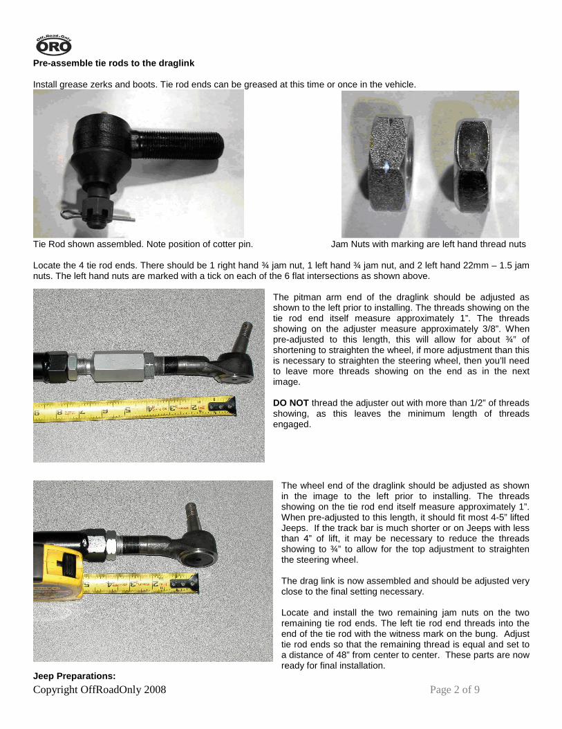
The pitman arm end of the draglink should be adjusted as shown to the left prior to installing. The threads showing on the tie rod end itself measure approximately 1”. The threads showing on the adjuster measure approximately 3/8”. When pre-adjusted to this length, this will allow for about ¾” of shortening to straighten the wheel, if more adjustment than this is necessary to straighten the steering wheel, then you’ll need to leave more threads showing on the end as in the next image. DO NOT thread the adjuster out with more than 1/2” of threads showing, as this leaves the minimum length of threads engaged.
The wheel end of the draglink should be adjusted as shown in the image to the left prior to installing. The threads showing on the tie rod end itself measure approximately 1”. When pre-adjusted to this length, it should fit most 4-5” lifted Jeeps. If the track bar is much shorter or on Jeeps with less than 4” of lift, it may be necessary to reduce the threads showing to ¾” to allow for the top adjustment to straighten the steering wheel. The drag link is now assembled and should be adjusted very close to the final setting necessary. Locate and install the two remaining jam nuts on the two remaining tie rod ends. The left tie rod end threads into the end of the tie rod with the witness mark on the bung. Adjust tie rod ends so that the remaining thread is equal and set to a distance of 48” from center to center. These parts are now ready for final installation.
Jeep Preparations:

Copyright OffRoadOnly 2008 Page 3 of 9
On Jeeps with aftermarket wheels or OEM wheels with wheel spacers, it may be possible to install the U-Turn Steering System without removing the tires. However, it is imperative that all fasteners are installed and tightened properly. If the wheel causes access interference to the ½-20 nuts for proper torque, please remove the wheels and torque properly. Loosen lug nuts. Raise the front of the Jeep by the axle, placing two jack stands under the axle at each end. Remove tire and wheel assembly. Removal of OEM components
Remove cotter pins from OEM tie rod castle nuts on both ends of draglink, and on the left tie rod end. The OEM steering can easily be removed as an assembly. Loosen and remove respective castle nuts. It will be necessary to remove the steering stabilizer at the axle end as well. The tie rod ends are all tapered and will require a pickle fork to remove. However there is also the big hammer method (shown at left). Once the nuts are loosened, use the large hammer and hit squarely perpendicular to the tapered tie rod shank. This impact will cause the joint to pop out. If you try this method, leave the castle nuts finger tight on the shank, as when it pops this will prevent it from falling out as well as possibly prevent damage to the threads from a misguided hammer. It is best to hit the mount in a manner that has the least amount of give, or basically, hit the pitman arm on the side of the tie rod taper, but hit in a manner directly towards the pitman shaft. This will result in the most impact and least amount of “give” in the arm.
Install Hubs
Next locate the black hub assemblies. The 3-hole unit goes on the passenger side, and the 2-hole unit on the driver side. Remove the forward and top wheel bearing retaining bolts on each side; these will require a 13mm 12point socket. Locate the ½-20 grade 8 x 2.5” long bolt with the cross-drilled hole in the threaded end. This bolt will be put together with a top lock nut, 2 washers and an aluminum bushing. Put on one washer and the aluminum bushing on the bolt. This will be ready for install shortly. As you install the hubs, start the wheel bearing bolts into their threads, and then place the ½” grade 8 bolt in place. At this point, if you hold the hub tight to the steering knuckle, you’ll see that the ¼” plate on the hub at the lower bolt is about 1/8-1/4” away from the knuckle surface. This is normal. The ¼” mild steel plate will easily conform to the knuckle and this flexing of the ¼” steel plate will not in any way affect the strength of the part.
Place the hub assembly so that the non-tapered hole is positioned over the OEM drag link attachment point. Push the ½-20 bolt/washer/bushing assembly up into the taper from the bottom. Place the washer and the nut on the top. There should be approximately 1/8” of the bushing remaining below the stock steering knuckle. This is the allowance for crush, the bushing will swedge into the taper providing a very tight, rigid placement of the bolt in the tapered hole. When tightening this nut, hold the bolt to prevent it from rotating, turning only the nut. Once the bushing is seated, tighten the wheel bearing bolts. Please refer to the picture on the left for correct assembly, noting the bushing stopping point. Place a few drops of Loc-Tite (recommended only if you wish to torque these bolts once, if you wish to check the torque during vehicle maintenance, do not apply Loc-Tite!) on the 2 wheel bearing retaining bolts and install. Start the threads and tighten a couple of turns to ensure that they are started properly.
Copyright OffRoadOnly 2008 Page 4 of 9
Torque fasteners Torque the Wheel bearing bolts first, 70ft-lbs Torque the ½-20 locknut, 90ft-lbs Install cotter pin in the ½-20 bolt. This pin is only to prevent the nut from turning completely off should it happen to loosen that much. Some Jeeps have 13mm 12 point bolts in the wheel bearings that have a large washer flange forged into the 12 point head. When these bolts are present (recent sampling has shown the newer models to be almost always like this) then we need to check the clearance between the washer head and the front axle shaft. The ¼” movement due to the aforementioned steel plate puts the washer heads closer to the axle shaft at full turn to lock. This, combined with the U-Turn angles allowing the inside tire to turn just a touch farther than the outside tire, the steering stops will allow the inside wheel to turn farther and most likely make contact to the axle shaft. This has been noticed more commonly with aftermarket shafts, however, in almost all instances, the marking is merely cosmetic and doesn’t damage anything. Adding a simple washer or two under the steering stops on each side will prevent it from making contact completely. Should you decide that you wish to not limit the turning, you may also check for the interference, and if noticed, slightly grind the washer part of the head down to clear the shaft. Install Draglink Straighten the steering wheel and adjust the right front wheel so it is pointing straight forward. This should put things in almost the right spot to just insert the tapered tie rod ends in the hub and pitman arm. Before installing the draglink, it is wise to rotate (carefully using a pliers) the tapered shaft so that the hole for the cotter pin is aligned parallel to the axle. This will aid in installing the cotter pin later. Install the draglink and start the castle nuts on the tie rod ends to secure. Install Tie Rod
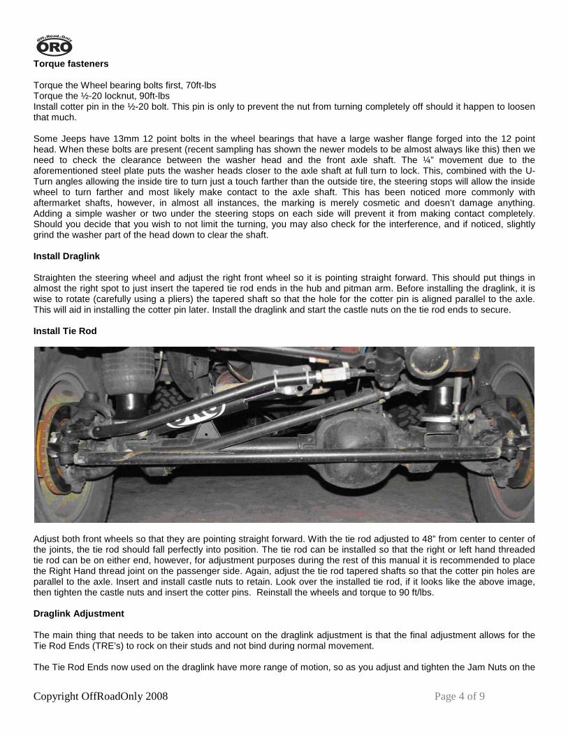
Adjust both front wheels so that they are pointing straight forward. With the tie rod adjusted to 48” from center to center of the joints, the tie rod should fall perfectly into position. The tie rod can be installed so that the right or left hand threaded tie rod can be on either end, however, for adjustment purposes during the rest of this manual it is recommended to place the Right Hand thread joint on the passenger side. Again, adjust the tie rod tapered shafts so that the cotter pin holes are parallel to the axle. Insert and install castle nuts to retain. Look over the installed tie rod, if it looks like the above image, then tighten the castle nuts and insert the cotter pins. Reinstall the wheels and torque to 90 ft/lbs. Draglink Adjustment
The main thing that needs to be taken into account on the draglink adjustment is that the final adjustment allows for the Tie Rod Ends (TRE’s) to rock on their studs and not bind during normal movement. The Tie Rod Ends now used on the draglink have more range of motion, so as you adjust and tighten the Jam Nuts on the

Copyright OffRoadOnly 2008 Page 5 of 9
draglink, rotate the draglink fore and aft and ensure that the lower bend does NOT rotate far enough down to contact the tie rod. IF it contacts the tie rod, most likely early Tie Rod End failure may occur. Once the draglink is adjusted to the proper length (Steering wheel is straight with wheels straight ahead) then the last step is tightening the jam nuts. Start by snugging the jam nuts and then grab the draglink. You should be able to rotate the draglink on its axis lengthwise by lifting and lowering the section of the draglink with the bend, much like the below right image. Make sure the draglink does not contact the tie rod at the lowest rotation, as in the picture below left.
The picture on the left shows the point of contact area between the draglink and tie rod. The picture on the right shows how you can rotate the draglink to ensure there is no contact to the tie rod, if there is, simply adjust the rotation of one tie rod end to prevent it from drooping that far.
At ride height, or with coils, put the weight of the Jeep on the springs. Adjust the draglink so that the Tie Rod ends max out rotation at the same time. Do not preload the ball and stud for the tie rod end by placing the tie rod ends at the opposite rotation of travel. Make sure jam nuts are snug to prevent the TRE’s from spinning in the draglink. Keep in mind the downward draglink rotation to prevent tie rod interference with the drag link. Now, the MOST important test, and failure to check this may result in early TRE failure, is to raise the Jeep (the body/chassis of the Jeep) and allow the front axle to droop to full extension. As you are getting close to the full droop condition, keep checking the draglink to see if the front to rear rotation is decreasing or ceases completely. If it does, then this adjustment will most definitely cause the TRE to fail the first time a steep hill is climbed or the first time the Jeep is lifted on a hoist by the chassis. If there is bind, you must loosen the jam nuts and further rotate the draglink to reduce the bind. DO NOT rotate the draglink any further than necessary, as too much rotation will be bad back at ride height!! Once you’ve achieved full droop and the draglink is still allowed to rotate on axis, then the TRE should live a good life. IF you adjusted the draglink at the droop condition, you will need to re-check for bind again as you go back to ride height. Adjusting the draglink during droop may allow you to place the lower bend straight below the draglink, it will be very good for the TRE at full droop, but upon lowering the chassis, it will most definitely contact the tie rod itself or by the time it lowers to right height will again take the TRE into a bind condition.
At ride height, with a long droop suspension, it is normal for the draglink to sit like shown in the image to
the left. Adjust toe At this point, it is recommended to see a professional installer to do the final adjustments on the steering. Only the toe and steering wheel centering specs should need to be adjusted if the vehicle had the proper caster setting before the install (Provided you didn’t do a full suspension install, control arm adjust or anything else to adjust the rotation of the axle, then there
should be no reason to adjust more than just the toe and center the steering wheel.)
Copyright OffRoadOnly 2008 Page 6 of 9
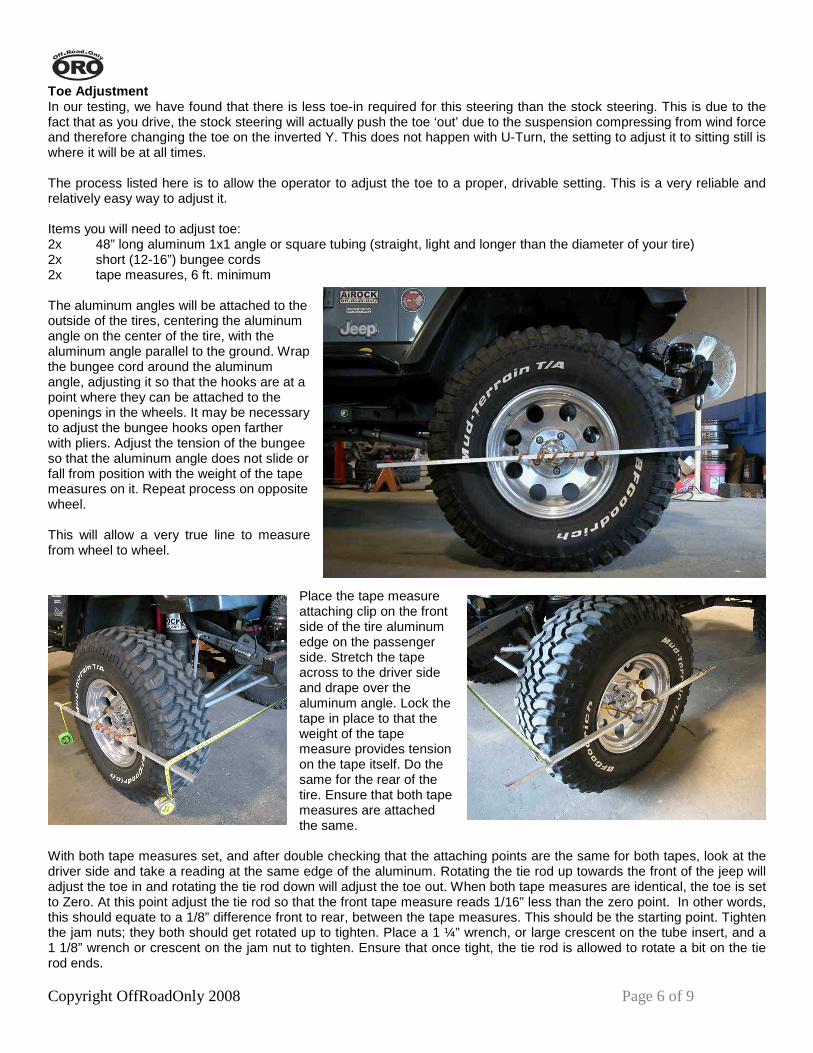
Toe Adjustment In our testing, we have found that there is less toe-in required for this steering than the stock steering. This is due to the fact that as you drive, the stock steering will actually push the toe ‘out’ due to the suspension compressing from wind force and therefore changing the toe on the inverted Y. This does not happen with U-Turn, the setting to adjust it to sitting still is where it will be at all times. The process listed here is to allow the operator to adjust the toe to a proper, drivable setting. This is a very reliable and relatively easy way to adjust it. Items you will need to adjust toe: 2x 48” long aluminum 1x1 angle or square tubing (straight, light and longer than the diameter of your tire) 2x short (12-16”) bungee cords 2x tape measures, 6 ft. minimum The aluminum angles will be attached to the outside of the tires, centering the aluminum angle on the center of the tire, with the aluminum angle parallel to the ground. Wrap the bungee cord around the aluminum angle, adjusting it so that the hooks are at a point where they can be attached to the openings in the wheels. It may be necessary to adjust the bungee hooks open farther with pliers. Adjust the tension of the bungee so that the aluminum angle does not slide or fall from position with the weight of the tape measures on it. Repeat process on opposite wheel. This will allow a very true line to measure from wheel to wheel.
Place the tape measure attaching clip on the front side of the tire aluminum edge on the passenger side. Stretch the tape across to the driver side and drape over the aluminum angle. Lock the tape in place to that the weight of the tape measure provides tension on the tape itself. Do the same for the rear of the tire. Ensure that both tape measures are attached the same.
With both tape measures set, and after double checking that the attaching points are the same for both tapes, look at the driver side and take a reading at the same edge of the aluminum. Rotating the tie rod up towards the front of the jeep will adjust the toe in and rotating the tie rod down will adjust the toe out. When both tape measures are identical, the toe is set to Zero. At this point adjust the tie rod so that the front tape measure reads 1/16” less than the zero point. In other words, this should equate to a 1/8” difference front to rear, between the tape measures. This should be the starting point. Tighten the jam nuts; they both should get rotated up to tighten. Place a 1 ¼” wrench, or large crescent on the tube insert, and a 1 1/8” wrench or crescent on the jam nut to tighten. Ensure that once tight, the tie rod is allowed to rotate a bit on the tie rod ends.

Copyright OffRoadOnly 2008 Page 7 of 9
Turn the wheel to the left, and watch the drag link for clearance at the track bar/sway bar bracket. If it clears through the arc of movement, then tighten the jam nut on the bend end. If not, rotate the drag link up or down to gain proper clearance, then tighten jam nut. Center steering wheel. After the toe setting, readjust the wheel if necessary to bring the tires as straight ahead as possible. Plan on adjusting the steering wheel after the test drive. Inspect the steering wheel. If it is at or near the centered position, then tighten the jam nuts on the adjuster sleeve. If it is not, then rotating the adjuster down should rotate the wheel to the left and up should rotate the wheel to the right. Once it is close, tighten the jam nuts and test drive. Pay attention to the position of the wheel and which way it needs to be adjusted. There is an easy way of keeping track of the wheel position while driving straight ahead: determine the center spot on the steering wheel and count how many little bumps on the back of the steering wheel there are left or right from that center spot. Service and Maintenance Grease the tie rod ends with a quality wheel bearing or chassis grease. Grease at each oil change interval or more often as dictated by terrain. Extremely wet or dusty environments should be greased more often. Driving: The toe setting plays a big factor in how the Jeep drives. Excessive toe in: A steering adjusted with too much toe in will be quick over center, twitchy, almost impossible to keep going straight on rough roads. Excessive toe out: A steering adjusted with too much toe out will be slow to respond to steering input and may also deliver an over steer condition once it does respond. Our Recommendations: 35-37” tires - toe set at zero to + 1/32 (1/16 toe in) 31-33” tires - toe set at +1/32 to +1/16 (1/16 to 1/8 toe in) Settings may be affected by tire pressure and other variables; each vehicle should be adjusted to the best drivability. 500 Mile check and then every 3000 miles after that: Remove the cotter pins and recheck the torque on the ½-20 grade 8 bolts. Reinstall cotter pins. Check torque on the 12point 13mm wheel bearing bolts. ***Only if Loc-tite is not applied! *** Check jam nuts to ensure they remain tight. Grease joints with quality wheel bearing or chassis grease if necessary. Steering Stabilizer Bracket The U-Turn contains a steering stabilizer bracket that gets U-Bolted to the drag link near the adjuster at the pitman arm. This bracket is designed to utilize most aftermarket and OEM steering stabilizers.
Steering Stabilizer Bracket
Shown with preferred 5/8 mounting stud (not included) ORO recommends the use of one of the following: • OffRoadOnly/QA1 UT-SS • Rancho RS5407 • Gabriel 6804SE • Monroe SC2928 (the Monroe stabilizer comes with a ½” stud that has a taper on it to attach to the
bracket. It does work, just doesn’t look as nice, see image on next page)
Copyright OffRoadOnly 2008 Page 8 of 9
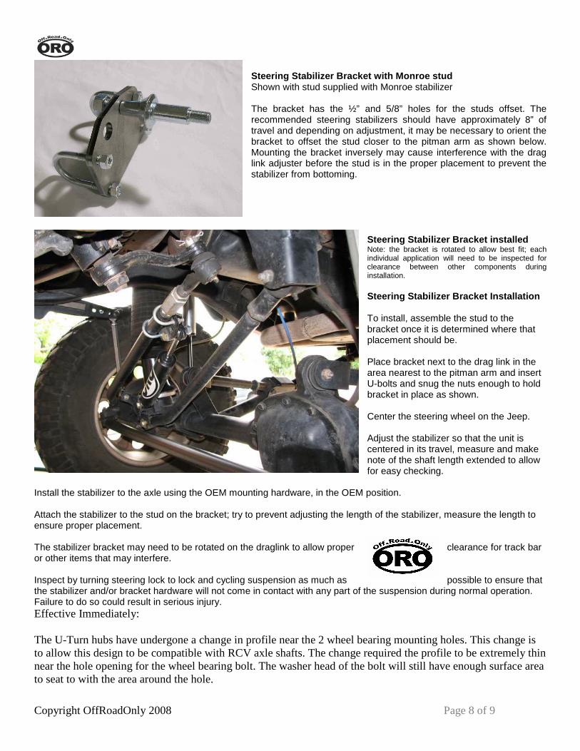
Steering Stabilizer Bracket with Monroe stud Shown with stud supplied with Monroe stabilizer The bracket has the ½” and 5/8” holes for the studs offset. The recommended steering stabilizers should have approximately 8” of travel and depending on adjustment, it may be necessary to orient the bracket to offset the stud closer to the pitman arm as shown below. Mounting the bracket inversely may cause interference with the drag link adjuster before the stud is in the proper placement to prevent the stabilizer from bottoming.
Steering Stabilizer Bracket installed Note: the bracket is rotated to allow best fit; each individual application will need to be inspected for clearance between other components during installation. Steering Stabilizer Bracket Installation To install, assemble the stud to the bracket once it is determined where that placement should be. Place bracket next to the drag link in the area nearest to the pitman arm and insert U-bolts and snug the nuts enough to hold bracket in place as shown. Center the steering wheel on the Jeep. Adjust the stabilizer so that the unit is centered in its travel, measure and make note of the shaft length extended to allow for easy checking.
Install the stabilizer to the axle using the OEM mounting hardware, in the OEM position. Attach the stabilizer to the stud on the bracket; try to prevent adjusting the length of the stabilizer, measure the length to ensure proper placement. The stabilizer bracket may need to be rotated on the draglink to allow proper clearance for track bar or other items that may interfere. Inspect by turning steering lock to lock and cycling suspension as much as possible to ensure that the stabilizer and/or bracket hardware will not come in contact with any part of the suspension during normal operation. Failure to do so could result in serious injury. Effective Immediately: The U-Turn hubs have undergone a change in profile near the 2 wheel bearing mounting holes. This change is to allow this design to be compatible with RCV axle shafts. The change required the profile to be extremely thin near the hole opening for the wheel bearing bolt. The washer head of the bolt will still have enough surface area to seat to with the area around the hole.

Copyright OffRoadOnly 2008 Page 9 of 9
Please see the image below to see the affected areas.