off-diagonal geometric phase in a neutron interferometer experiment
TRANSCRIPT
VOLUME 87, NUMBER 7 P H Y S I C A L R E V I E W L E T T E R S 13 AUGUST 2001
070401-1
Off-Diagonal Geometric Phase in a Neutron Interferometer Experiment
Y. Hasegawa,1 R. Loidl,2 M. Baron,2 G. Badurek,1 and H. Rauch1
1Atominstitut der Österreichischen Universitäten, Stadionallee 2, A-1020 Wien, Austria2Institut Laue Langevin, B.P. 156, F-38042 Grenoble Cedex 9, France
(Received 23 March 2001; published 26 July 2001)
Off-diagonal geometric phases acquired by an evolution of a 1�2-spin system have been observed bymeans of a polarized neutron interferometer. We have successfully measured the off-diagonal phase fornoncyclic evolutions even when the diagonal geometric phase is undefined. Our data confirm theoreticalpredictions and the results illustrate the significance of the off-diagonal phase.
DOI: 10.1103/PhysRevLett.87.070401 PACS numbers: 03.65.Vf, 03.75.Dg, 07.60.– j, 42.50.–p
When a quantum system is transported through a curveC in parameter space, a geometric phase component devel-ops which is Hamiltonian independent and depends solelyupon curve C. This geometric phase factor was first rec-ognized by Pancharatnam [1] and reformulated for adia-batic transport in a closed loop by Berry [2], which arousedconsiderable interest [3]. The concept of geometric phaseby Berry was generalized for nonadiabatic transport [4].Many experiments to determine the geometric phase werereported [3]: early neutron experiments were made withregard to spinor evolution of neutrons [5,6]. Quite recently,off-diagonal matrix elements, �Cj jCk�, of nondegenerateeingenstates, jCi�, were investigated and found to carrythe geometrical phase information even when the conven-tional diagonal geometric phase is undefined [7]. The for-malism was applied to the deformed microwave resonatorexperiment [8].
Neutron interferometer experiments have made animpact in fundamental quantum and neutron physics formore than two decades [9–12]. In particular, those witha polarized incident beam served as an almost ideal toolto investigate properties of a 1�2-spin system in a superiorway [13]: for instance, spinor superposition [14,15],
0031-9007�01�87(7)�070401(4)$15.00
double resonance flipper experiments [16], and geometricphase measurements [17,18]. A neutron interferometerwith coupled interference loops was used to create and tomeasure the spin-independent geometric phase in kind ofa double-slit experiment [19].
In this Letter, we describe the neutron interferometricexperiment that explicitly observes the off-diagonal geo-metric phase acquired by the noncyclic spinor evolution ofa 1�2-spin system. An incident polarized neutron beamsplits into two beam paths and each spinor is rotated toinduce appropriate spinor evolutions. With the help ofa polarization analysis, the off-diagonal geometric phasesappear as the phase shifts of the intensity modulations.
We consider here the time evolution of a spinor jC�t��,describing a 1�2-spin system, namely, a neutron. As one ofthe simplest but nevertheless the most important examples,we treat here the unitary evolution, U�t�, of a spinor lyingin the x-y plane by a magnetic field parallel to z. The initialspinor is assumed to be jC1�0��; the orthogonal spinor isgiven by jC2�0��. The initial spinor, jC1�0��, evolvesto jC1�t�� � U�t� jC1�0��. This is a parallel-transportprocess [20] with invariant phase and therefore jC1k�t�� �jC1�t�� in our particular circumstances. The off-diagonalgeometric phase, g12 [7] is expressed as
g12 � F����C1k�0� jC2k�t�� ? �C2k�0� jC1k�t����� � F����C1�0� jU�t�jC2�0�� ? �C2�0� jU�t�jC1�0������ F��C1�0� jU�t� ? P���jC2�0����� ? P���jC2�0����� ? U�t� jC1�0��� , (1)
where F�z� � z�jzj for a complex quantity z fi 0, andP�jC�� � jC� �Cj, which is a projection operator to thestate jC� which will be achieved in an experiment by theuse of a polarizer.
An interferometric measurement with polarized neu-trons allows us to observe this phase factor g12 as thephase shift of the oscillations, when the intensity modula-tion to be measured is given by
I � jeix ? Py���jC2�0����� ? Uy�t� ? jC1�0��1 P���jC2�0����� ? U�t� ? jC1�0��j2, (2)
where x is the phase shift induced by an auxiliary phaseshifter. Taking Py�jC�� � P�jC�� and Uy�t� � U21�t�,Eq. (2) is rewritten with abbreviating jC6�0�� to jC6� as
I � jP�jC2�� ? �eix ? U21�t� 1 U�t�� ? jC1�j2. (3)
This describes the intensity of the beam obtained fromthe polarized incident spinor (the third factor), split andaffected by appropriate spinor rotations with the phase shift(the middle factor), and finally measured with the spinoranalysis of the orthogonal spinor to the incident (the firstfactor).
Writing down the incident spinor jC1� � 10 (the cor-
responding orthogonal spinor is given by jC2� � 01 ) in
the j6y� spinor basis, the unitary evolution by the mag-netic field in the 1z direction is given by
U�t� �
∑cos�vLt�2� 2 sin�vLt�2�sin�vLt�2� cos�vLt�2�
∏(4)
© 2001 The American Physical Society 070401-1
VOLUME 87, NUMBER 7 P H Y S I C A L R E V I E W L E T T E R S 13 AUGUST 2001
with the Larmor frequency vL. Equation (3) now re-duces to I � sin2�vLt�2� �1 1 cos�x 1 p���2. Thus, theoff-diagonal geometric phase is expected to be p and is in-dependent of the spinor rotation angle, vLt.
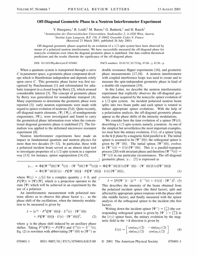
The experiment was carried out at the perfect crystal in-terferometer beam line S18 at the high flux reactor at theInstitut Laue Langevin (ILL) [21]. A schematic view ofthe experimental setup is shown in Fig. 1. The neutronbeam was monochromatized to have a mean wavelengthof l0 � 1.92 Å (Dl�l0 � 0.02) by the 220 Bragg reflec-tion of a Si perfect crystal monochromator placed in thethermal neutron guide H25. This incident beam was po-larized vertically, i.e., perpendicular to the beam trajectorydefining z, by magnetic-prism refractions. Its cross sectionwas confined to 8 3 8 mm2 and the beam passed througha spin rotator F, used for tuning the polar angle of the in-cident spinor, and entered a skew-symmetric triple-Laueinterferometer. This interferometer was adjusted to give220 reflection in a nondispersive arrangement relative tothe monochromator. A pair of water-cooled Helmholtzcoils produced a fairly uniform magnetic guide field, B0z,around the interferometer. These coils were enclosed byan isothermal box to achieve reasonable thermal environ-mental isolation. A magnetically saturated Heusler crys-tal together with a Larmor accelerator and a rectangularp�2-spin turner enabled the selection of neutrons with cer-tain polarization directions.
In order to estimate depolarization, the efficiency of thespinor rotations in the spin analyzing part, and other im-perfections of the setup, the interferometer was adjustedto accept only spin-up polarized neutrons, i.e., j1z�, withthe spin rotator F turned off. The fraction of the j1z�component was measured to be 0.92 with the use of thespin turner. Since the present measurement demands thepolarization of the incident beam to lie in the x-y plane,
FIG. 1. Schematic view of the whole experimental setup toobserve the off-diagonal geometric phase. An incident polarizedneutron beam splits into two beam paths and each spinor isrotated to induce appropriate spinor evolutions. An appropriatespin analysis enables one to observe the off-diagonal geometricphase.
070401-2
the spin rotator F was turned on to rotate the j1z� spinorto the j1y� direction. The magnetic guide field was opti-mized to B0 � 18 G to avoid additional depolarization ofthe spinor in the x-y plane. the measurement with the useof the Larmor accelerator revealed that the fraction of thedesired component was reduced to 0.87, which was stillhigh enough to accomplish the measurements. Nonessen-tial spinor precessions are induced by the guide field allthrough the beam trajectories. Nevertheless, the com-mutability between the operators for the essential spinorrotations [U and U21 in Eq. (3)] and the nonessential ro-tations (guide field) allows one to compensate for thesenonessential precessions behind the interferometer.
The unitary evolutions, U�t� and U21�t�, were realizedin the experiment by setting the magnetic field in the twoidentical spin rotators in an antiparallel direction. In prac-tice, a pair of spin rotators -I and -II was inserted in thesplit beam paths. These spin rotators were identical dccoils except for the current directions, i.e., the directionsof the induced magnetic fields. They were connected inseries to give the same strengths of the magnetic fields inthe antiparallel direction. Each coil was made of a 8 mmwide and 0.5 mm thick Al band, specially D doped to avoidsmall angle scattering in the insulator, wound onto a water-cooled Cu frame. These coils induced 180± spinor rota-tions when operated at 9.8 A dissipating about 0.6 W each.The rotation angle was tuned by adjusting the current, ifnecessary, accompanied by changing their polarities. Spe-cial attention was paid to eliminate both heat and vibrationtransmission to the interferometer.
Interferograms were obtained in two detectors by rotat-ing a 5 mm thick parallel-sided Al plate as a phase shifter.The detectors were placed downstream of the interfering Obeam in the forward direction behind a spin analysis sys-tem, and directly in the H beam in the reflected direction.Two intensities, one with spinor rotations and the otherwithout them, were accumulated for each phase shifter po-sition: typically one with 10 sec measurement times withthe spin rotators -I and -II turned on, after measuring theother for 20 sec with them turned off. This procedure gavesimultaneously two interferograms with and without spinorrotations to avoid instabilities producing undesired phaseshifts between the two measurements. The contrast of theinterference oscillations, obtained by the O detector, wastypically 64% for the empty interferometer and was re-duced to about 40% after inserting the dual spin rotators.This contrast dropped in some situations to about 30%,mainly due to thermal disturbances. We repeated the samemeasurements at least three times to ensure that the resultswere reliable.
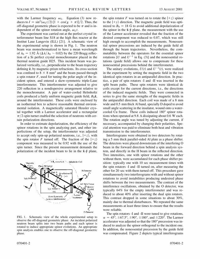
The spin rotators -I and -II were tuned to give rotations,a � 45±, 667.5±, 690±, 6180±, and 6220±. The Larmoraccelerator was adjusted so that the 180±precession was in-duced to analyze the spinor orthogonal to the incident one.In addition, the nonessential precession by the guide fieldwas compensated. Figure 2 depicts typical interferograms
070401-2
VOLUME 87, NUMBER 7 P H Y S I C A L R E V I E W L E T T E R S 13 AUGUST 2001
FIG. 2. Typical interferograms with various spin rotationangles, a, in comparison with the unaffected beam (withoutspin rotations). The patterns with spinor rotations show thephase shift of 180± to the beam without spinor rotations.
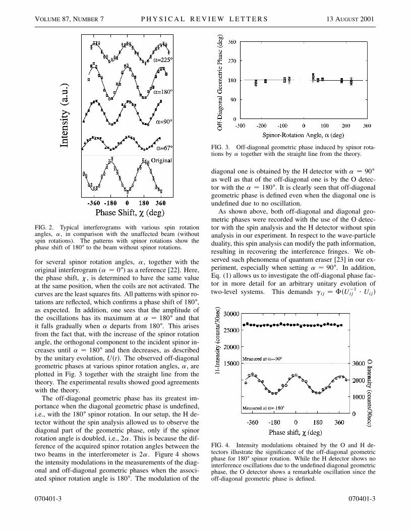
for several spinor rotation angles, a, together with theoriginal interferogram (a � 0±) as a reference [22]. Here,the phase shift, x, is determined to have the same valueat the same position, when the coils are not activated. Thecurves are the least squares fits. All patterns with spinor ro-tations are reflected, which confirms a phase shift of 180±,as expected. In addition, one sees that the amplitude ofthe oscillations has its maximum at a � 180± and thatit falls gradually when a departs from 180±. This arisesfrom the fact that, with the increase of the spinor rotationangle, the orthogonal component to the incident spinor in-creases until a � 180± and then decreases, as describedby the unitary evolution, U�t�. The observed off-diagonalgeometric phases at various spinor rotation angles, a, areplotted in Fig. 3 together with the straight line from thetheory. The experimental results showed good agreementswith the theory.
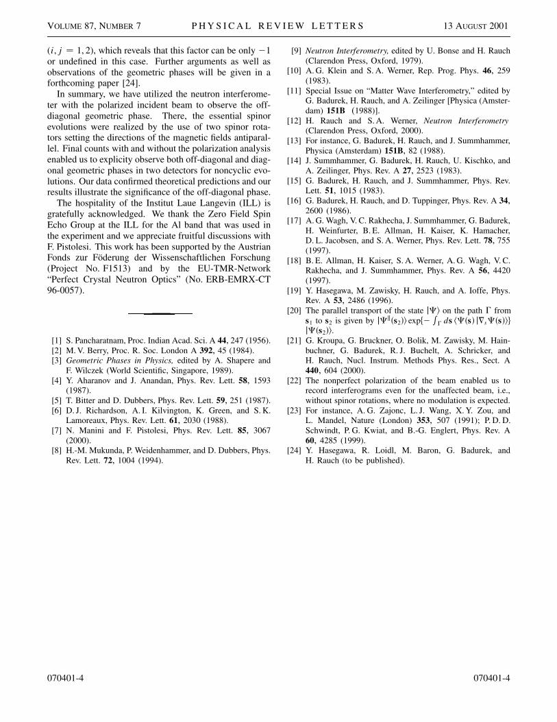
The off-diagonal geometric phase has its greatest im-portance when the diagonal geometric phase is undefined,i.e., with the 180± spinor rotation. In our setup, the H de-tector without the spin analysis allowed us to observe thediagonal part of the geometric phase, only if the spinorrotation angle is doubled, i.e., 2a. This is because the dif-ference of the acquired spinor rotation angles between thetwo beams in the interferometer is 2a. Figure 4 showsthe intensity modulations in the measurements of the diag-onal and off-diagonal geometric phases when the associ-ated spinor rotation angle is 180±. The modulation of the
070401-3
FIG. 3. Off-diagonal geometric phase induced by spinor rota-tions by a together with the straight line from the theory.
diagonal one is obtained by the H detector with a � 90±
as well as that of the off-diagonal one is by the O detec-tor with the a � 180±. It is clearly seen that off-diagonalgeometric phase is defined even when the diagonal one isundefined due to no oscillation.
As shown above, both off-diagonal and diagonal geo-metric phases were recorded with the use of the O detec-tor with the spin analysis and the H detector without spinanalysis in our experiment. In respect to the wave-particleduality, this spin analysis can modify the path information,resulting in recovering the interference fringes. We ob-served such phenomena of quantum eraser [23] in our ex-periment, especially when setting a � 90±. In addition,Eq. (1) allows us to investigate the off-diagonal phase fac-tor in more detail for an arbitrary unitary evolution oftwo-level systems. This demands gij � F�U21
ij ? Uij�
FIG. 4. Intensity modulations obtained by the O and H de-tectors illustrate the significance of the off-diagonal geometricphase for 180± spinor rotation. While the H detector shows nointerference oscillations due to the undefined diagonal geometricphase, the O detector shows a remarkable oscillation since theoff-diagonal geometric phase is defined.
070401-3
VOLUME 87, NUMBER 7 P H Y S I C A L R E V I E W L E T T E R S 13 AUGUST 2001
(i, j � 1, 2), which reveals that this factor can be only 21or undefined in this case. Further arguments as well asobservations of the geometric phases will be given in aforthcoming paper [24].
In summary, we have utilized the neutron interferome-ter with the polarized incident beam to observe the off-diagonal geometric phase. There, the essential spinorevolutions were realized by the use of two spinor rota-tors setting the directions of the magnetic fields antiparal-lel. Final counts with and without the polarization analysisenabled us to explicity observe both off-diagonal and diag-onal geometric phases in two detectors for noncyclic evo-lutions. Our data confirmed theoretical predictions and ourresults illustrate the significance of the off-diagonal phase.
The hospitality of the Institut Laue Langevin (ILL) isgratefully acknowledged. We thank the Zero Field SpinEcho Group at the ILL for the Al band that was used inthe experiment and we appreciate fruitful discussions withF. Pistolesi. This work has been supported by the AustrianFonds zur Föderung der Wissenschaftlichen Forschung(Project No. F1513) and by the EU-TMR-Network“Perfect Crystal Neutron Optics” (No. ERB-EMRX-CT96-0057).
[1] S. Pancharatnam, Proc. Indian Acad. Sci. A 44, 247 (1956).[2] M. V. Berry, Proc. R. Soc. London A 392, 45 (1984).[3] Geometric Phases in Physics, edited by A. Shapere and
F. Wilczek (World Scientific, Singapore, 1989).[4] Y. Aharanov and J. Anandan, Phys. Rev. Lett. 58, 1593
(1987).[5] T. Bitter and D. Dubbers, Phys. Rev. Lett. 59, 251 (1987).[6] D. J. Richardson, A. I. Kilvington, K. Green, and S. K.
Lamoreaux, Phys. Rev. Lett. 61, 2030 (1988).[7] N. Manini and F. Pistolesi, Phys. Rev. Lett. 85, 3067
(2000).[8] H.-M. Mukunda, P. Weidenhammer, and D. Dubbers, Phys.
Rev. Lett. 72, 1004 (1994).
070401-4
[9] Neutron Interferometry, edited by U. Bonse and H. Rauch(Clarendon Press, Oxford, 1979).
[10] A. G. Klein and S. A. Werner, Rep. Prog. Phys. 46, 259(1983).
[11] Special Issue on “Matter Wave Interferometry,” edited byG. Badurek, H. Rauch, and A. Zeilinger [Physica (Amster-dam) 151B (1988)].
[12] H. Rauch and S. A. Werner, Neutron Interferometry(Clarendon Press, Oxford, 2000).
[13] For instance, G. Badurek, H. Rauch, and J. Summhammer,Physica (Amsterdam) 151B, 82 (1988).
[14] J. Summhammer, G. Badurek, H. Rauch, U. Kischko, andA. Zeilinger, Phys. Rev. A 27, 2523 (1983).
[15] G. Badurek, H. Rauch, and J. Summhammer, Phys. Rev.Lett. 51, 1015 (1983).
[16] G. Badurek, H. Rauch, and D. Tuppinger, Phys. Rev. A 34,2600 (1986).
[17] A. G. Wagh, V. C. Rakhecha, J. Summhammer, G. Badurek,H. Weinfurter, B. E. Allman, H. Kaiser, K. Hamacher,D. L. Jacobsen, and S. A. Werner, Phys. Rev. Lett. 78, 755(1997).
[18] B. E. Allman, H. Kaiser, S. A. Werner, A. G. Wagh, V. C.Rakhecha, and J. Summhammer, Phys. Rev. A 56, 4420(1997).
[19] Y. Hasegawa, M. Zawisky, H. Rauch, and A. Ioffe, Phys.Rev. A 53, 2486 (1996).
[20] The parallel transport of the state jC� on the path G froms1 to s2 is given by jCk�s2�� exp�2
RG ds �C�s� j=sC�s���
jC�s2��.[21] G. Kroupa, G. Bruckner, O. Bolik, M. Zawisky, M. Hain-
buchner, G. Badurek, R. J. Buchelt, A. Schricker, andH. Rauch, Nucl. Instrum. Methods Phys. Res., Sect. A440, 604 (2000).
[22] The nonperfect polarization of the beam enabled us torecord interferograms even for the unaffected beam, i.e.,without spinor rotations, where no modulation is expected.
[23] For instance, A. G. Zajonc, L. J. Wang, X. Y. Zou, andL. Mandel, Nature (London) 353, 507 (1991); P. D. D.Schwindt, P. G. Kwiat, and B.-G. Englert, Phys. Rev. A60, 4285 (1999).
[24] Y. Hasegawa, R. Loidl, M. Baron, G. Badurek, andH. Rauch (to be published).
070401-4