of the berlin type walls in deepxcav. - deep excavation · verification of the berlin type walls in...
TRANSCRIPT
Developed from Ce.A.S. S.r.l, Italy and Deep Excavation LLC, U.S.A.
Edited from the Staff of Deep Excavation LLC. 1
Verification of the Berlin type walls in DeepXcav.
DeepXcav software program (Version 2011)
(ParatiePlus within Italy)
Version 1.0
Issued: 5‐Nov‐2010
Deep Excavation LLC
www.deepexcavation.com

Developed from Ce.A.S. S.r.l, Italy and Deep Excavation LLC, U.S.A.
Edited from the Staff of Deep Excavation LLC. 2
Object: Verification of the Berlin type walls in DeepXcav.
Let’s consider the example presented in the previous figure.
This example includes a tangent pile wall with the following properties:
Section: 180 x 10 mm
Material: Fe510
Wall spacing: 0,5 m

Developed from Ce.A.S. S.r.l, Italy and Deep Excavation LLC, U.S.A.
Edited from the Staff of Deep Excavation LLC. 3
The choice to include the filling concrete to the pile, refers only to the calculation of the equivalent
thickness and therefore the analysis of the structure.
During structural verification only the steel tangent pile wall resistance is included.
The verification has been made in agreement with the Eurocode cases.
The model was calculated according to the approach A1 + M1 + R1 (EC7, 2007: DA‐1).

Developed from Ce.A.S. S.r.l, Italy and Deep Excavation LLC, U.S.A.
Edited from the Staff of Deep Excavation LLC. 4
Next, lateral result diagrams are presented:

Developed from Ce.A.S. S.r.l, Italy and Deep Excavation LLC, U.S.A.
Edited from the Staff of Deep Excavation LLC. 5
• Verification of compression / traction
The verification of the compression / traction verifies compression / traction which is calculated from
the program but not included in the output.
This can be seen in file .EXT (in the folder Documents/DeepXcavtemporaryfiles/steel).
In this file are presented all the verification checks for every wal section and for every Stage.
The verification took place according to the paragraph (EC7, 2007: DA‐1).
The factors of safety are relevant to the Eurocode 2 and 3:
EC3: CSTVEREC3 MODULE: START
***********************
Partial safety factors as used in this code
Gamma M0 = 1.000
Gamma M1 = 1.000
Gamma M2 = 1.250
Verification to compression:
Section no. 66 at x= 6401.000 [mm]
selected class for current cross section = 1
6.2.4 Compression for class 1 cross sections
Ratio =‐26.57 / 3236. =0.8210E‐02
Shear Verification
According to the paragraph 6.2.6 of UNI EN 1993 1‐1:2005:
The results are visible in the form of Shear resistance.

Developed from Ce.A.S. S.r.l, Italy and Deep Excavation LLC, U.S.A.
Edited from the Staff of Deep Excavation LLC. 6
Shear Ratio
This can be seen in file .EXT (in the folder Documents/DeepXcavtemporaryfiles/steel).
6.2.6 Shear resistance check
6.2.6 Shear resistance check
Z direction : Shear Area Av = 5803. mm2
Vsd = ‐7.767 kN , VplRd = 1189. kN, ratio = 0.6530E‐02
Verification of bending moment / bending moment and Axial force
According to the paragraph 6.2.9 of UNI EN 1993 1‐1:2005 (in the case that also axial force is present on
the bulkhead) or to the paragraph 6.2.5 in the case that only bending moment is present.
The includes carries out a classification of the section, as it can be seen in the output file.
Section no. 66 at x= 6401.000 [mm]
selected class for current cross section = 1
The results are presented in exploitation of rates of limits in limits of resisting moment.

Developed from Ce.A.S. S.r.l, Italy and Deep Excavation LLC, U.S.A.
Edited from the Staff of Deep Excavation LLC. 7
RATIO M Moment + CAP.M
The extensive summary results are reported at the end of analysis with the greatest rates of exploitation
for every stage. The values TSF M + N are coinciding to the values RAT. M as seen on the model.
This can be seen in file .EXT (in the folder Documents/DeepXcavtemporaryfiles/steel).

Developed from Ce.A.S. S.r.l, Italy and Deep Excavation LLC, U.S.A.
Edited from the Staff of Deep Excavation LLC. 8
The verification is performed for the most critical element in the final stage.
6.2.9.1 Bending and axial force check for Class 1 and 2 sections
Shape type TUBO
Interaction between M and N is account for
(for notation see paragraph 6.2.9.1)
aw = 0.000 af = 0.000
alfa = 2.000 beta = 2.000
MVNyRd= 120.5 MVNzRd= 120.5 ratio= 0.4116
(eqn. 6.31 )
Instability verification
The instability verification is performed according to the paragraph 6.3.3. of UNI EN 1993 1‐1:2005 .
The calculation of the critical moment Mcr is done using the appendix F of UNI EN 1993 1‐1: 1992.
The pile comes subdivided automatic from the program in elements; it points out the eventual presence
of ties, the contribution of excavation and the back contribution of the bulkhead.
Regarding the contribution of excavation, to simulate the effect of trespass of the ground, the bulkhead
comes subdivided in small elements.
Developed from Ce.A.S. S.r.l, Italy and Deep Excavation LLC, U.S.A.
Edited from the Staff of Deep Excavation LLC. 9
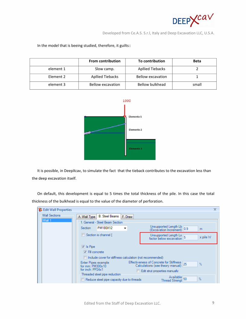
In the model that is beeing studied, therefore, it guilts::
From contribution To contribution Beta
element 1 Slow camp. Apllied Tiebacks 2
Element 2 Apllied Tiebacks Bellow excavation 1
element 3 Bellow excavation Bellow bulkhead small
It is possible, in DeepXcav, to simulate the fact that the tieback contributes to the excavation less than
the deep excavation itself.
On default, this development is equal to 5 times the total thickness of the pile. In this case the total
thickness of the bulkhead is equal to the value of the diameter of perforation.
Developed from Ce.A.S. S.r.l, Italy and Deep Excavation LLC, U.S.A.
Edited from the Staff of Deep Excavation LLC. 10
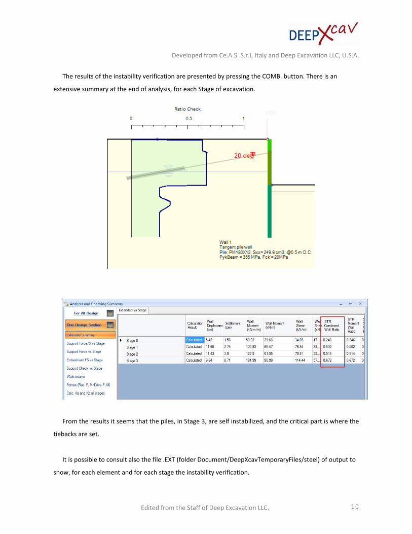
The results of the instability verification are presented by pressing the COMB. button. There is an
extensive summary at the end of analysis, for each Stage of excavation.
From the results it seems that the piles, in Stage 3, are self instabilized, and the critical part is where the
tiebacks are set.
It is possible to consult also the file .EXT (folder Document/DeepXcavTemporaryFiles/steel) of output to
show, for each element and for each stage the instability verification.

Developed from Ce.A.S. S.r.l, Italy and Deep Excavation LLC, U.S.A.
Edited from the Staff of Deep Excavation LLC. 11
EC3: START BUCKLING CHECKS
CSTVEREC3: STABILITY CHECKS FOR PARTIAL SPAN NO. 1
zstart = 0.000000 [mm] zend= 2000.000 [mm]
CSTVEREC3: STABILITY CHECKS FOR PARTIAL SPAN NO. 2
zstart = 2000.000 [mm] zend= 7000.000 [mm]
buckl. length about x‐x = 6400.000 [mm]
Regarding to the second excavation, having considered the not supported length of the excavation
equal to 5*W (W = sp. hole perforation = 250 mm) = 1.25 m, the length of free inflection results is:
l = l0 * Beta = 6,25 m * 1 = 6,25.
CSTVEREC3: STABILITY CHECKS FOR PARTIAL SPAN NO. 3
zstart = 7000.000 [mm] zend= 15000.00 [mm]
buckl. length about x‐x = 1000.000 [mm]
buckl. length about y‐y = 1000.000 [mm]
Finally it comes restored the piece of the file of relevant output to verify the second element, that is
critical:
CSTVEREC3: EQUIVALENT MOMENTS CALCULATION
Start calculation ‐ Moment:Y Bracing:Z
TABLE B.3 : XMIN = 2001.0 XMAX = 6999.0
BXMIN= 0.80993E+08 BXMAX= ‐0.43099E+08
X(1) = 0.0000 X(N) = 15000.
M(1) = 1000.0 M(N) = 0.0000
Developed from Ce.A.S. S.r.l, Italy and Deep Excavation LLC, U.S.A.
Edited from the Staff of Deep Excavation LLC. 12
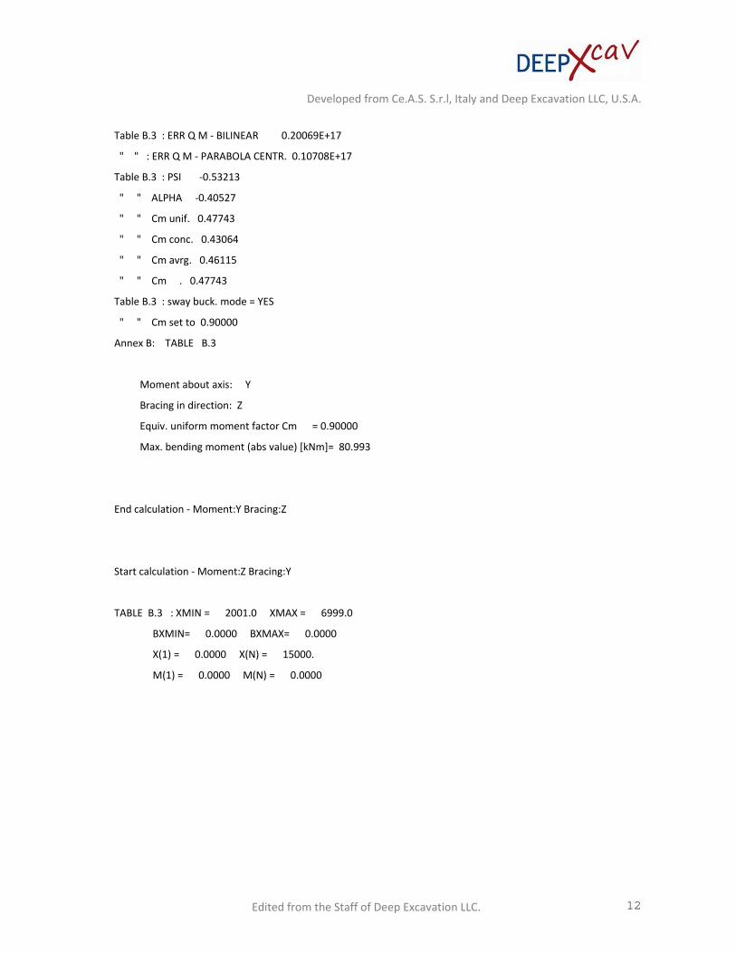
Table B.3 : ERR Q M ‐ BILINEAR 0.20069E+17
" " : ERR Q M ‐ PARABOLA CENTR. 0.10708E+17
Table B.3 : PSI ‐0.53213
" " ALPHA ‐0.40527
" " Cm unif. 0.47743
" " Cm conc. 0.43064
" " Cm avrg. 0.46115
" " Cm . 0.47743
Table B.3 : sway buck. mode = YES
" " Cm set to 0.90000
Annex B: TABLE B.3
Moment about axis: Y
Bracing in direction: Z
Equiv. uniform moment factor Cm = 0.90000
Max. bending moment (abs value) [kNm]= 80.993
End calculation ‐ Moment:Y Bracing:Z
Start calculation ‐ Moment:Z Bracing:Y
TABLE B.3 : XMIN = 2001.0 XMAX = 6999.0
BXMIN= 0.0000 BXMAX= 0.0000
X(1) = 0.0000 X(N) = 15000.
M(1) = 0.0000 M(N) = 0.0000
Developed from Ce.A.S. S.r.l, Italy and Deep Excavation LLC, U.S.A.
Edited from the Staff of Deep Excavation LLC. 13
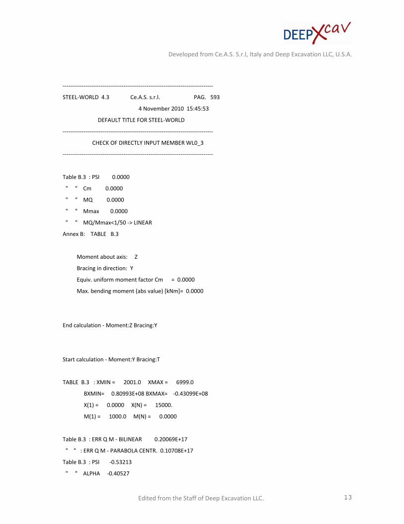
‐‐‐‐‐‐‐‐‐‐‐‐‐‐‐‐‐‐‐‐‐‐‐‐‐‐‐‐‐‐‐‐‐‐‐‐‐‐‐‐‐‐‐‐‐‐‐‐‐‐‐‐‐‐‐‐‐‐‐‐‐‐‐‐‐‐‐‐‐‐‐‐‐‐‐‐‐‐‐
STEEL‐WORLD 4.3 Ce.A.S. s.r.l. PAG. 593
4 November 2010 15:45:53
DEFAULT TITLE FOR STEEL‐WORLD
‐‐‐‐‐‐‐‐‐‐‐‐‐‐‐‐‐‐‐‐‐‐‐‐‐‐‐‐‐‐‐‐‐‐‐‐‐‐‐‐‐‐‐‐‐‐‐‐‐‐‐‐‐‐‐‐‐‐‐‐‐‐‐‐‐‐‐‐‐‐‐‐‐‐‐‐‐‐‐
CHECK OF DIRECTLY INPUT MEMBER WL0_3
‐‐‐‐‐‐‐‐‐‐‐‐‐‐‐‐‐‐‐‐‐‐‐‐‐‐‐‐‐‐‐‐‐‐‐‐‐‐‐‐‐‐‐‐‐‐‐‐‐‐‐‐‐‐‐‐‐‐‐‐‐‐‐‐‐‐‐‐‐‐‐‐‐‐‐‐‐‐‐
Table B.3 : PSI 0.0000
" " Cm 0.0000
" " MQ 0.0000
" " Mmax 0.0000
" " MQ/Mmax<1/50 ‐> LINEAR
Annex B: TABLE B.3
Moment about axis: Z
Bracing in direction: Y
Equiv. uniform moment factor Cm = 0.0000
Max. bending moment (abs value) [kNm]= 0.0000
End calculation ‐ Moment:Z Bracing:Y
Start calculation ‐ Moment:Y Bracing:T
TABLE B.3 : XMIN = 2001.0 XMAX = 6999.0
BXMIN= 0.80993E+08 BXMAX= ‐0.43099E+08
X(1) = 0.0000 X(N) = 15000.
M(1) = 1000.0 M(N) = 0.0000
Table B.3 : ERR Q M ‐ BILINEAR 0.20069E+17
" " : ERR Q M ‐ PARABOLA CENTR. 0.10708E+17
Table B.3 : PSI ‐0.53213
" " ALPHA ‐0.40527

Developed from Ce.A.S. S.r.l, Italy and Deep Excavation LLC, U.S.A.
Edited from the Staff of Deep Excavation LLC. 14
" " Cm unif. 0.47743
" " Cm conc. 0.43064
" " Cm avrg. 0.46115
" " Cm . 0.47743
Annex B: TABLE B.3
Moment about axis: Y
Bracing in direction: T
Equiv. uniform moment factor Cm = 0.47743
Max. bending moment (abs value) [kNm]= 80.993
End calculation ‐ Moment:Y Bracing:T
CSTVEREC3: CRITICAL MOMENT CALCULATION (ANNEX F)
SUBROUTINE CSEC3BMASPECT ‐ DIFFERENCE'S DIAGRAMS
NO. OF SAMPLE (NSAMPLE) 152
MINIMUM NO. OF SAMPLE (NSAM) 152
FIRST INTERNAL POINT (KSIN1) 22
LAST INTERNAL POINT (KSIN2) 71
X CASE 1 CASE 2 CASE 3 CASE 4 CASE 5 LINEAR
‐‐‐‐‐‐‐‐‐‐‐‐‐‐‐‐‐‐‐‐‐‐‐‐‐‐‐‐‐‐‐‐‐‐‐‐‐‐‐‐‐‐‐‐‐‐‐‐‐‐‐‐‐‐‐‐‐‐‐‐‐‐‐‐‐‐‐‐‐‐‐‐‐‐‐‐‐
2001. 0.8099E+08 0.1535E+08 0.8099E+08 0.4817E+08 0.8099E+08 0.000
2199. 0.7455E+08 0.1889E+08 0.7215E+08 0.4193E+08 0.7475E+08‐0.6525E+07
ANNEX F: GENERAL FORMULA F.1.2 ‐ (EQN F 2)
M cr y = 20599.9489401 [kN*m]
L.T. LENGTH = 2500.0 [mm]
WARP LENGTH = 5000.0 [mm]
PATTERN MOM. =F.1.2 5

Developed from Ce.A.S. S.r.l, Italy and Deep Excavation LLC, U.S.A.
Edited from the Staff of Deep Excavation LLC. 15
C1 = 1.0100
C2 = 0.41000
C3 = 1.8900
Zg (Za‐Zs) = 0.0000 [mm]
Zj " = 0.0000 [mm]
Torsional Inertia = 0.71867E+09 [mm^4]
Warping constant = 0.0000 [mm^6]
AREE ‐> 0.171E+12 0.885E+11 0.171E+12 0.171E+12 0.146E+12 0.171E+12 0.873E+11
TABLE 6.6: Correction factor Kc
Axe = y Kc = 0.664
************ STABILITY CHECK ********
************ EUROCODE 3 ‐ 1993 ********
USER WORK AUTOMATIC
SELECTED WORK 633
**** E C 3 SECTION 6.3.3 ****
Member class (classification was made before)= 1
**** E C 3 SECTION 6.3.3 ****
Member class (classification was made before)= 1
Tab 6.2 SHAPE TYPE=TUBO
Axis =Y; Curve A
6.3.1.1: FOR BUCKLING ABOUT AXIS Y
SLENDERNESS (L/i) = 128.9415
LAMBDA sup = 1.703818
Developed from Ce.A.S. S.r.l, Italy and Deep Excavation LLC, U.S.A.
Edited from the Staff of Deep Excavation LLC. 16
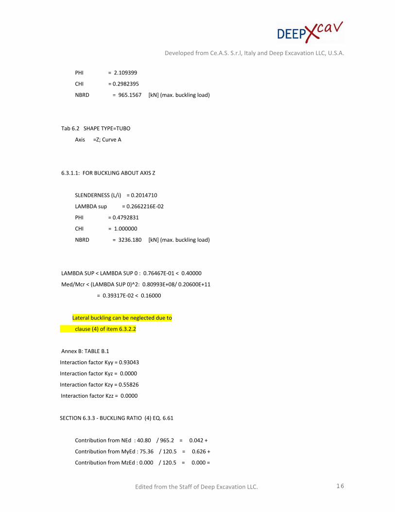
PHI = 2.109399
CHI = 0.2982395
NBRD = 965.1567 [kN] (max. buckling load)
Tab 6.2 SHAPE TYPE=TUBO
Axis =Z; Curve A
6.3.1.1: FOR BUCKLING ABOUT AXIS Z
SLENDERNESS (L/i) = 0.2014710
LAMBDA sup = 0.2662216E‐02
PHI = 0.4792831
CHI = 1.000000
NBRD = 3236.180 [kN] (max. buckling load)
LAMBDA SUP < LAMBDA SUP 0 : 0.76467E‐01 < 0.40000
Med/Mcr < (LAMBDA SUP 0)^2: 0.80993E+08/ 0.20600E+11
= 0.39317E‐02 < 0.16000
Lateral buckling can be neglected due to
clause (4) of item 6.3.2.2
Annex B: TABLE B.1
Interaction factor Kyy = 0.93043
Interaction factor Kyz = 0.0000
Interaction factor Kzy = 0.55826
Interaction factor Kzz = 0.0000
SECTION 6.3.3 ‐ BUCKLING RATIO (4) EQ. 6.61
Contribution from NEd : 40.80 / 965.2 = 0.042 +
Contribution from MyEd : 75.36 / 120.5 = 0.626 +
Contribution from MzEd : 0.000 / 120.5 = 0.000 =

Developed from Ce.A.S. S.r.l, Italy and Deep Excavation LLC, U.S.A.
Edited from the Staff of Deep Excavation LLC. 17
‐‐‐‐‐‐‐‐‐‐‐‐‐‐‐
Sum of above contributions = 0.668
SECTION 6.3.3 ‐ BUCKLING RATIO (4) EQ. 6.62
Contribution from NEd : 40.80 / 3236. = 0.013 +
Contribution from MyEd : 45.22 / 120.5 = 0.375 +
Contribution from MzEd : 0.000 / 120.5 = 0.000 =
‐‐‐‐‐‐‐‐‐‐‐‐‐‐‐
Sum of above contributions = 0.388
E C 3 ‐ SECTION 6.3.3
NSD (MAX COMPRESSION FORCE [KN]) ‐40.798
RATIOB (STABILTY WITHOUT LATERAL TORSION) EQ 6.61 0.66791
RATIOB1 (STABILTY WITHOUT LATERAL TORSION) EQ 6.62 0.38799
RATIO = max {RATIOB,RATIOB1} 0.66791