of iitr 3htstitutr of ratio iingitturg
TRANSCRIPT
VOLUME 16 FEBRUARY, 1928 NUMBER 2
PROCEEDINGSof
iItr 3htstitutr of Ratioiingitturg
RE
Published Monthly ByTHE INSTITUTE OF RADIO ENGINEERS
Publication Office: 450-454 Ahnaip St., Menasha, Wis.
Editorial and Advertising Departments37 West 39th Street, New York, N.Y.
Subscription $10.00 per Annum in the United States$11.00 in all other Countries
General Information and Subscription Rates on Page 107.
THE CHOICEof
LEADINGMANUFACTURERS
For over four years Thordarsontransformers have predominated inthe receivers and power units of
- leading radio manufacturers.- Such patronage is not an accident.
It stands as a positive proof of a--- superiority of product. It demon-
strates the effectiveness of a policyof service rendered to the n'th de-gree by an efficient and smoothrunning organization.
We are at present manufacturingover twelve hundred different typesof transformers. Among our cus-tomers are more than a hundredradio manufacturers.
Thordarson engineers always standready to help you with your trans-former problems.
PROMPT DELIVERYRIGHT PRICES
TI.1,111/11111\ 01.11/1111114,111111/11MIII Ilf11/./411151V1)11171i
TtioypgsoNfupreme in ,Musical 7,1E-tirinancef TIRANSFORMEizs JeTil
THORDARSON ELECTRIC MANUFACTURING CO.Transformer specialists since 1895WORLDS OLDEST AND LARGEST EXCLUSIVE TRANSFORMER MAKERS
Chicago. U.S.A. (357,When writing to advertisers mention of the Proceedings will be mutually helpfuL
Whether socket power or battery operatedyou'll find Faradon in the better sets
Since 1907 Faradon expertshave met electrostatic con-
denser needs with capacitors especiallydesigned for each particular purpose.
There are several hundred types in rou-tine production covering nearly all re-
quirements. Write our engineering de-partment for any detailed data desired
for special applications.
WIRELESS SPECIALTY APPARATUS CO.Jamaica Plain
BOSTON, MASS., U. S. A.Established 1907
ElectrostaticCondensers
for adpurposes
1604
When writing to advertisers mention of the Proceedings will be mutually helpful.
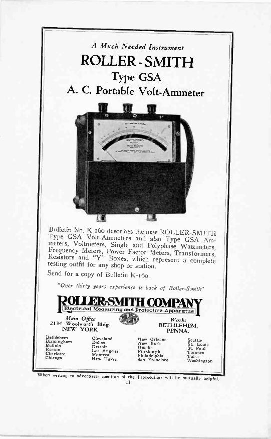
A Much Needed Instrument
ROLLER - SMITHType GSA
A. C. Portable Volt-Ammeter
Bulletin No. K-160 describes the new ROLLER -SMITHType GSA Volt -Ammeters and also Type GSA Am-meters, Voltmeters, Single and Polyphase Wattmeters,Frequency Meters, Power Factor Meters, Transformers,Resistors and "Y" Boxes, which represent a completetesting outfit for any shop or station.Send for a copy of Bulletin K -16o.
"Over thirty years experience is back of Roller-Stnith"
FmaElectrical. Measurtng and Protective Apparatus]Main Office
2134 Woolworth Bldg.NEW YORK
BethlehemBirminghamBuffaloBostonCharlotteChicago
ClevelandDallasDetroitLos AngelesMontrealNew Haven
WorksBETHLEHEM,
PENNA.TI ew OrleansNew YorkOmahaPittsburghPhiladelphiaSan Francisco
SeattleSt. LouisSt. PaulTorontoTulsaWashington
When writing to advertisers mention of the Proceedings will be mutually helpful.
More than ascore of radiodesigners official-ly specify Ham-marlund Preci-s i o n Productsfor their newestcircuits.
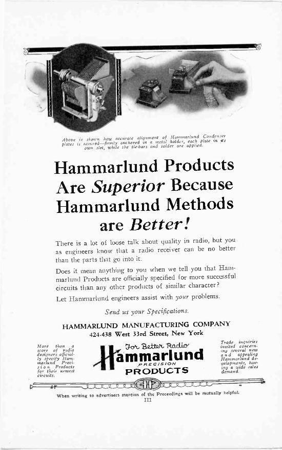
Above is shown how accurate alignment of Hammarlund Condenserplates is assured-firmly anchored in a metal holder, each plate in its
own slot, while the tie -bars and solder are applied.
Hammarlund ProductsAre Superior BecauseHammarlund Methods
are Better!There is a lot of loose talk about quality in radio, but you
as engineers know that a radio receiver can be no better
than the parts that go into it.
Does it mean anything to you when we tell you that Ham-marlund Products are officially specified for more successfulcircuits than any other products of similar character?
Let Hammarlund engineers assist with your problems.
Send us your Specifications.
HAMMARLUND MANUFACTURING COMPANY424-438 West 33rd Street, New York
SzttOt.
ammarlundPIREC /SION
PRODUCTS
Trade inquiriesinvited concern--ng several newa n d appealingHammarlund de-...ielopments, hay-ing a wide salesdemand.
When writing to advertisers mention of the Proceedings will be mutually helpful.III
to
AmENIXior AxxstizwslAtizOvilt tAssukTgeste AHENTILAN AvitENTivoi I AN EATIVAN AM MIRAN
Finer Performancethan you've ever enjoyed!
Made available by complete
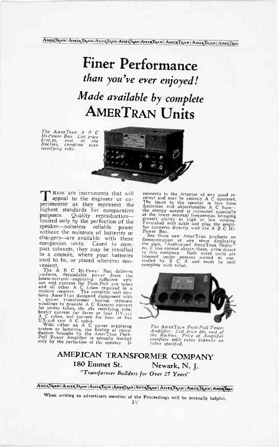
AMERTRAN UnitsThe AMERTRAN A B CHi -Power Box. List price$102.50, east of theRockies, complete withrectifying tube.
THESE are instruments that willappeal to the engineer or ex-
perimentor as they represent thehighest standards for comparativepurposes. Quality reproduction-limited only by the perfection of thespeaker-noiseless reliable powerwithout the nuisance of batteries orchargers-are available with thesecompanion units. Cased in com-pact cabinets, they may be installedin a console, where your batteriesused to be, or placed wherever con-venient.
The A B C Hi -Power Box deliversuniform, dependable power from thehouse-current-supplying sufficient volt-age and current for Push -Pull 2i o tubesand all other A C tubes required in amodern receiver. The complete unit con-tains AmerTran designed equipment witha power transformer having separatewindings to provide A C filament currentfor power tubes, the 28t rectifying tube,heater current for three or four UY-227A C tubes, and current for four or fiveUX-226 raw A C tubes.
With either an A C power supplyingsystem or batteries, the fidelity of repro-duction brought by the AmerTran Push-Pull Power Amplifier is actually limitedonly by the perfection of the speaker. It
connects to the detector of any good re-ceiver and may be entirely A C operated.The input to the speaker is free fromdistortion and objectionable A C hum-the energy output is increased especiallyat the lower musical frequencies bringinggreater clarity at high or low volume.Furnished with cable and plug the ampli-fier connects directly with the A B C Hi -Power Box.
See these new AmerTran products ondemonstration at any store displayingthe sign, "Authorized AmerTran Dealer"or, if you cannot obtain them, write directto this company. Both wired units arelicensed under patents owned or con-trolled by R C A and must be soldcomplete with tubes.
The AMERTRAN Push -Pull PowerAmplifier. List price $6o, east ofthe Rockies. Price of Amplifiercomplete with tubes depends ontubes specified.
AMERICAN TRANSFORMER COMPANY180 Emmet St. Newark, N. J.
"Transformer Builders for Over 27 Years"
AmwArsykri f AmakINAN tAnzyTtywai,lbaigivonAt4ENTwi1 Armaiwa 1 AmENTivottAboxithyus
When writing to advertisers mention of the Proceedings will be mutually helpful.Iv
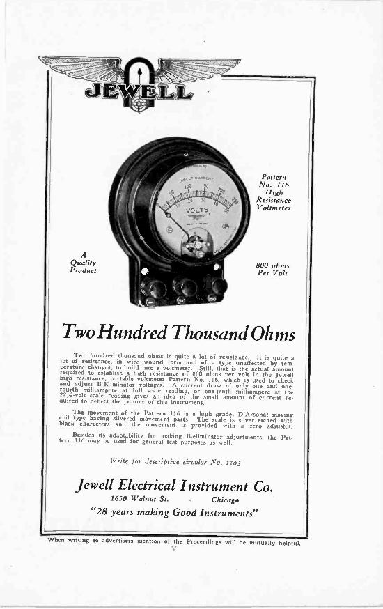
AQualityProduct
PatternNo. 116
HighResistanceVoltmeter
800 ohmsPer Volt
Two Hundred Thousand OhmsTwo hundred thousand ohms is quite a lot of resistance. It is quite alot of resistance, in wire wound form and of a type unaffected by tem-
perature changes, to build into a voltmeter. Still, that is the actual amountrequired to establish a high resistance of 800 ohms per volt in the Jewellhigh resistance, portable voltmeter Pattern No. 116, which is used to checkand adjust B -Eliminator voltages. A current draw of only one and one-fourth milliampere at full scale reading, or one tenth milliampere at the22% -volt scale reading gives an idea of the small amount of current re-quired to deflect the pointer of this instrument.
The movement of the Pattern 116 is a high grade, D'Arsonal movingcoil type having silvered movement parts. The scale is silver etched withblack characters and the movement is provided with a zero adjuster.
Besides its adaptability for making B -eliminator adjustments, the Pat-tern 116 may be used for general test purposes as well.
Write for descriptive circular No. Iso3
Jewell Electrical Instrument Co.1650 Walnut St. - Chicago
"28 years making Good Instruments"
When writing to advertisers mention of the Proceedings will be mutually helpfulV
Radio - Is - BETTER - With - Dry - Battery - Power
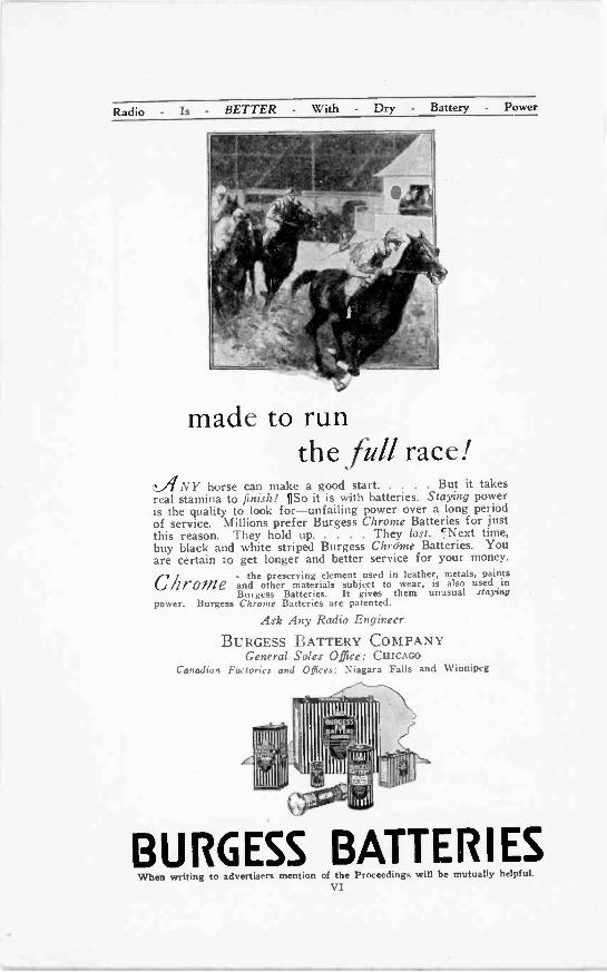
made to runthe full race!
c.ANY horse can make a good start But it takesreal stamina to finish! ¶So it is with batteries. Staying poweris the quality to look for-unfailing power over a long periodof service. Millions prefer Burgess Chrome Batteries for justthis reason. They hold up They last. ¶Next time,buy black and white striped Burgess Chrome Batteries. Youare certain to get longer and better service for your money.
-the preserving element used in leather, metals, paintsChrome and other materials subject to wear, is also used in
Burgess Batteries. It gives them unusual atayingpower. Burgess Chrome Batteries are patented.
Ask Any Radio Engineer
BURGESS BATTERY COMPANYGeneral Sales Office: CHICAGO
Canadian Factories and Offices: Niagara Falls and Winnipeg
BURGESS BATTERIESWhen writing to advertisers mention of the Proceedings will be mutually helpful.
VI
%Jim) *
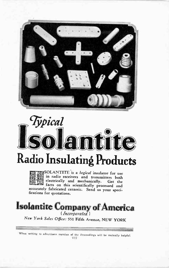
Radio Insulating ProductsSOLANTITE is a logical insulator for usein radio receivers and transmitters bothelectrically and mechanically. Get thefacts on this scientifically processed and
accurately fabricated ceramic. Send us your speci-fications for quotations.
any America( Incorporated)
New York Sales Office: 551 Fifth Avenue, NEW YORK
When writing to advertisers mention of the Proceedings will be mutually helpful.VII
Nine Reasons WhyRadiotrons UX-280 and UX-281
Are Most Economical Rectifiers
1 Fewer Condensers required in rectifyingand filtering circuits (Buffer Condensersacross transformer secondary not required).
2 Lower Capacity Condensers can be used(Wave form of UX-280 and UX-281 doesnot have jagged peaks, thus simplifyingfilter requirements).
3 Lower Voltage Condensers can be employedeffecting further manufacturing economy.
4 High initial surge voltage from transformernot required as UX-280 and UX-281 startat any voltage. Thus design is simplifiedand possible failure of condensers due toerratic surge peak is eliminated.
5 Possibility of failure to operate due to in-sufficient breakdown voltage is eliminated.
6 Erratic and noisy operation is not experi-enced with highly evacuated tubes such asRadiotrons UX-280 and UX-281.
7 New Ribbon Filament makes tubes un-usually rugged.
8 Long life.9 The UX-280 will furnish adequate B and C
voltage for a receiver using RadiotronUX-171A at maximum plate voltage.
RADIO CORPORATION OF AMERICANew York Chicago San Francisco
RCA RadiotronMADE BY THE MAKERS OF THE RADIOLA
When writing to advertisers mention of the Proceedings will be mutually helpfui.VIII
PROCEEDINGS OF
Anstituir of Rabin Eitgiur_srliVolume 16 February, 1928 Number 2
CONTENTS
Officers and Board of Direction PIZCommittees . . 108Institute Sections . . 110Institute Activities. . 116
News of the Sections 118Committee Work 120
Charles Bayne Aiken, "A Precision Method for the Measurement ofHigh Frequencies' . . . . . . 125
J. W. Horton and W. A. Marrison, "Precision Determination ofFrequency" . . . ..... . 137
George Rodwin and Theodore A. Smith, "A Radio -Frequency Oscillatorfor Receiver Investigations" . . . . . . . 155
L. W. Austin and Miss I. J. Wymore, "On the Influence of SolarActivity on Radio Transmission" 166
E. 0. Hulburt, "Ionization in the Upper Atmosphere" . . . . 174H. B. Maris, "A Theory of the Upper Atmosphere and Meteors" . . 177Knox Mcllwain and W. S. Thompson, "A Radio Field Strength Survey
of Philadelphia" . . . . . . . . . 181Manfred von Ardenne, "On the Theory of Power Amplification" . . 193Alexander Nyman, "Condenser Shunt for Measurement of High -
Frequency Currents of Large Magnitude" . . 208Book Reviews . . . . . . .... 218Geographical List of Members Elected January 4, 1928 . 224
GENERAL INFORMATIONThe PROCEEDINGS of the Institute are published monthly and contain
the papers and the discussions thereon as presented at meetings.Payment of the annual dues by a member entitles him to one copy of
each number of the PROCEEDINGS issued during the period of his membership.Subscriptions to the PROCEEDINGS are received from non-members at the
rate of $1.00 per copy or ;10.00 per year. To foreign countries the rates are$1.10 per copy or ;11.00 per year. A discount of 25 per cent is allowed tolibraries and booksellers.
The right to reprint limited portions or abstracts of the articles, dis-cussions, or editorial notes in the PROCEEDINGS is granted on the express con-ditions that specific reference shall be made to the source of such material.Diagrams and photographs in the PROCEEDINGS may not be reproduced with-out securing permission to do so from the Institute through the Secretary.
It is understood that the statements and opinions given in the PROCEED-INGS are the views of the individual members to whom they are credited, andare not binding on the membership of the Institute as a whole.
Entered as second class matter at the Post Office at Menasha, Wisconsin.Acceptance for mailing at special rate of postage provided for in the Act
of February 28, 1925, embodied in paragraph 4, Section 412, P. L. and R.Authorized October 26, 1927.
Copyright, 1928, byTHE INSTITUTE OF RADIO ENGINEERS, Inc.
Publication Office 450-454 Ahnaip Street, Menasha, Wis.Editorial and Advertising Departments, 37 West 39th St., New York, N.Y.
OFFICERS AND BOARD OF DIRECTION, 1928(Terms expire January 1, 1929, except as otherwise noted)
TreasurerMELVILLE EASTHAM
ARTHUR BATCHELLER
W. G. CADY
PresidentALFRED N. GOLDSMITH
Vice -PresidentL. E. WHITTEMORE
Managers
A. H. GREBE
L. A. HAZELTINE
J. V. L. HOGAN(Serving until Jan. 1, 1930)
EditorALFRED N. GOLDSMITH
Acting SecretaryJOHN M. CLAYTON
R. H. MARRIOTT
R. A. Ilmairic(Serving until Jan. 1, 1930)
J. H. DELLINGER(Serving until Jan. 1, 1931)
R. H. MANSON(Serving until Jan. 1, 1931)
Junior Past PresidentsDONALD MCNICOL
RALPH BOWN
Associate EditorGEORGE R. METCALFE
Committees of the Institute of Radio Engineers, 197
Committee on Meetings and PapersR. H. MARRIOTT, ChairmanSTUART BALLANTINER. R. BATCHERCARL DREHERW. G. H. FINCHERICH HAUSMANNS. S. KIRBYG. W. PICKARDPAUL WEEKSW. WILSON
Committee on AdmissionsF. CONRAD, ChairmanARTHUR BATCHELERHARRY F. DARTC. P. EDWARDSA. H. GREBEL. A. HAZELTINER. A. HEISING
L. M. Hum,F. H. KROGERA. G. LEEF. K. VREELAND
Committee on Revision of the Con-stitution
J. H. DELLINGER, ChairmanJ. V. L. HoGANDONALD McNicol,
Committee on PublicityW. G. H. FINCH, ChairmanC. E. BUTTERFIELDDAVID CASEMORRIN E. DUNLAPE. EHLERTL. W. HATRYE. H. HANSENLLOYD JACQUETJ. F. J. MAHER
108
J. G. UZMANNWILLIE K. WINGR. F. YATES
Committee on MembershipHARRY F. DART, ChairmanM. C. BATSELM. BERGERF. R. BRICKGEORGE BURGHARDE. M. DELORAINEDR. L. J. DinarC. P. EDWARDSW. G. H. FINCHC. M. JAMEY, JR.ROBERT S. KRUSEWILLIAM J. LEEPENDLETON E. LEHDEC. L. RICHARDSONF. H. SCHNELLE. R. SHUTEG. S. TURNERE. H. Maim'Committee on Institute Sections
DAVID H. GAGE, ChairmanM. BERGERL. F. FULLERD. HEPBURNL. G. PACENTM. C. RYPINSKIE. R. SHUTE
All Section Secretaries ex -officio
Committees of the Institute-(Continued)
Committee on StandardizationL. E. WHFITEMORE, ChairmanM. C. BATSELEDWARD BENNETTE. L. CHAFFEEJ. H. DELLINGERMELVILLE EASTHAMG. P. EDWARDSGENERAL FERRIEA. N. GOLDSMITHL. A. HAZELTINEJ. V. L. HOGANW. E. HOLLANDL. M. Hcia.F. A. KOLSTERMAJOR J. 0. MAUBORGNER. H. MANSONDONALD MCNICOLE. L. NELSONH. S. OSBORNEH. B. RICHMONDLT. COMDR. W. J. RUBLEE. H. SHAUGHNESSYH. M. TURNERC. A. WRIGHTHIDETSUGU YAGIJ. ZENNECK
109
ChairmanWalter Van Nostrand
ChairmanGeorge W. Pierce
ChairmanL. C. F. Hoyle
ChairmanA. M. Patience
ChairmanJohn H. Miller
ChairmanJohn R. Martin
ChairmanW. G. Cady
ChairmanThomas E. Clark
ChairmanL. Taufenbach
ChairmanJ. C. Van Horn
ChairmanHarvey Klumb
ChairmanTyng Libby
ChairmanA. Hoyt Taylor
ROCHESTER, N.Y.
F. W.
SAN FRANCISCO
INSTITUTE SECTIONSATLANTA SECTION
Secretary -TreasurerGeorge Llewellyn, Room 524, Post Office
Bldg., Atlanta, Ga.BOSTON SECTION
Secretary -TreasurerMelville Eastham, 30 State St.,
Cambridge, Mass.BUFFALO-NIAGARA SECTION
SecretaryC. J. Porter, 141 Milton Street,
Buffalo, New YorkCANADIAN SECTION
SecretaryC. C. Meredith, 110 Church St., Toronto, Ontario
CHICAGO SECTIONSecretary
H. E. Kranz, 4540 Armitage Ave., Chicago, Ill.
CLEVELAND SECTIONSecretary -Treasurer
B. W. David, 3223 Ormond Road,Cleveland Heights, Ohio
CONNECTICUT VALLEY SECTIONSecretary -Treasurer
George W. Pettengill Jr., P.O. Box 551Ludlow, Mass.
DETROIT SECTIONSecretary -Treasurer
W. R. Hoffman, 615 West Lafayette Blvd.,Detroit, Mich.
LOS ANGELES SECTIONSecretary
W. W. Lindsay, Jr., 927 La Jolla Ave.,Hollywood, Cal.
PHILADELPHIA SECTIONSecretary
John C. Mevius, 1533 Pine St.,Philadelphia, Pa.
SECTIONSecretary
Reynolds, 1360 University Ave.,Rochester, N. Y.
SECTIONSecretary -Treasurer
D. B. McGown, Custom House,San Francisco, Cal.
SEATTLE SECTIONSecretary -Treasurer
W. A. Kleist 820 Dexter Horton Bldg.Seattle, Wash.
WASHINGTON SECTIONSecretary -Treasurer
F. P. Guthrie, 122 Conn. Ave., Washington, D.0
110

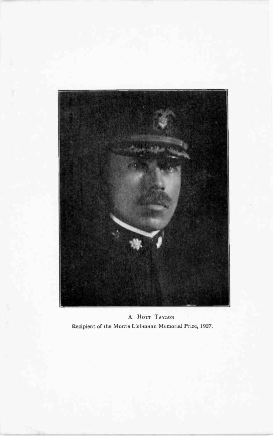
A. HOI r TAYLOR
Recipient of the Morris Liebmann Memorial Prize, 1927.
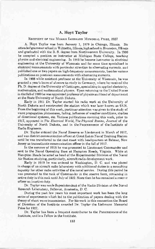
A. Hoyt TaylorRECIPIENT OF THE MORRIS LIEBMANN MEMORIAL PRIZE, 1927
A. Hoyt Taylor was born January 1, 1879 in Chicago, Illinois. Heattended grammar school in Wilmette, Illinois, high school in Evanston, Illinoisand graduated with the B. S. degree from Northwestern University. In 1900he accepted a position as instructor at Michigan State College, teachingphysics and electrical engineering. In 1903 he became instructor in electricalengineering at the University of Wisconsin and for some time specialized inelectrical measurements with particular attention to alternating currents, andpublished one or two papers on high -frequency measurements, besides variouspublications on precision measurements with alternating currents.
In 1908 while assistant professor at the University of Wisconsin, he wasgranted a year's leave of absence to study in Germany, where he received thePh. D. degree at the University of Gottingen, specializing in applied electricity,mathematics, and mathematical physics. Upon returning to the United Statesin the fall of 1909 he was appointed professor of physics and head of departmentat the State University of North Dakota.
Early in 1911 Dr. Taylor started his radio work at the University ofNorth Dakota and constructed the station which was later known as 9XN.From the beginning of this work, particuar attention was given to the study ofwave propagation phenomena, fading, influence of weather conditions, studiesof directional systems, etc. Various publications covering this work, prior to1917, appeared in The Electrical World, The Physical Review, Journal of theUniversity of North Dakota, and in the PROCEEDINGS of the Institute ofRadio Engineers.
Dr. Taylor entered the Naval Reserve as Lieutenant in March of 1917,and was district communication officer at Great Lakes Naval Training Stationuntil he was transferred to the east coast with headquarters at Belmar, NewJersey as transatlantic communication officer in the fall of 1917.
In the summer of 1918 he was promoted to Lieutenant Commander andsent to the Naval Operating Base at Hampton Roads, Virginia. While atHampton Roads he acted as head of the Experimental Division of the NavalAir Station studying, particularly, aircraft radio development work.
Early in 1919 he was ordered to Washington, D. C. and was placedin charge of an aircraft radio laboratory with additional duties in a consultingcapacity for other radio activities of the naval service. During this period hewas promoted to the rank of Commander in the reserve force, remaining inactive duty in this rank until July of 1922. Since then he has remained a reserveofficer on inactive duty.
Dr. Taylor was made Superintendent of the Radio Division at the NavalResearch Laboratory, Bellevue, Anacostia, D. C.
During the past few years his most important work has been the longseries of experiments which led to the publication of papers dealing with thetheory of short wave transmission. For his work in this connection the Boardof Direction of the Institute awarded Dr. Taylor the Liebmann MemorialPrize for 1927.
Dr. Taylor has been a frequent contributor to the PROCEEDINGS of theInstitute, and is a Fellow in the Institute.
113
CONTRIBUTORS TO THIS ISSUEAiken, Charles B.: Born at New Orleans, Louisiana, October 6, 1902.
Marine radio operator, summers 1918-1921. Received B. S. degree in physics,Tulane University, 1923; M. S. degree, Harvard, 1924; M. A. degree, Harvard,1925. Winner of Harvard Engineering School Prize Scholarship for 1924-1925.Whiting fellow in physics, 1924-1926. Research Engineer, Mason, Slichterand Hay, Consulting Engineers, 1926 to date. Associate member of theInstitute.
Austin, L. W.: Born at Orwell, Vermont, October 30,1867. Received A.B.degree, Middlebury College, 1889; Ph. D. degree, University of Strassburg,1893. Instructor and assistant professor, University of Wisconsin, 1893-1901;research work, University of Berlin, 1901-1902; Bureau of Standards, Wash-ington, D. C. since 1904; head of U. S. Naval Radio Research Laboratory,1908-1923; chief of Radio Physics Laboratory, 1923 to date. Dr. Austin wasPresident of the Institute in 1914 and served on its Board of Direction from1915 to 1917. In 1927 he was awarded the Institute Medal of Honor. Hiscontributions to the PROCEEDINGS have been frequent. He is a Fellow of theInstitute.
Horton, J. H.: Born at Ipswich, Massachusetts, December 18, 1889.Received B.S. degree in electro-chemistry, Massachusetts Institute of Tech-nology, 1914. Instructor, Massachusetts Institute of Technology, 1914-1916;Research engineer with Western Electric Company, 1916-1925 (on leave ofabsence 1917-1918 as technical expert with U. S. Navy working on methodsfor detection and location of submarines at experimental stations in thiscountry). At present research engineer with Bell Telephone Laboratories,engaged in development of systems for the transmission of pictures andtelevision; also in development of methods for the precision measurement offrequency. Associate member of the Institute.
Hulbert, E. 0.: Born October 12,1890. Received Ph. D. degree in physics,Johns Hopkins University, 1915. Taught undergraduate and graduatecw.:rses at Western Reserve University, Johns Hopkins University andUniversity of Iowa. With American Expeditionary Force in France for twoyears as Lieutenant and later Captain in the Signal Corps. At present Dr.Hulburt is Superintendent of the Heat and Light Division, Naval ResearchLaboratory, Bellevue, D. C. He is the author of a number of papers onexperimental and theoretical work in spectroscopy, physical optics and radiotelegraphy.
Mcllwain, Knox: Received B.S. degree, Princeton University, 1918; B.S.in E. E., University of Pennsylvania, 1921. U. S. Navy 1917-1919. Engineer-ing department of Bell Telephone Company of Pennsylvania, 1921-1924.Instructor at Moore School of Electrical Engineering, University of Pennsyl-vania, 1924 to date.
Maris, H. B.: Born in 1885. Received A.B. degree, University of Mich-igan, 1909; M.S. degree, 1910; Ph.D. degree, Johns Hopkins University, 1927.Associate Professor of Physics at Birminghan-Southern College, 1922. Pro-fessor of physics, Emory.and Henry College, 1923. Consulting physicist, NavalResearch Laboratory, 1925 to date; researches, photo -elastic studies, and the-oretical study of the upper atmosphere.
114
Contributors to this Issue 115
Morrison, W. A.: Served in Royal Flying Corps, later Royal Air Force,in Canada, 1917-1918; received B.S. degree in physics, Queens University,Canada, 1920; A.M. degree in physics and mathematics, Harvard University,1921. Research engineer with Western Electric Company 1921-1925; researchengineer with Bell Telephone Laboratories, engaged in the study of picturetransmission and methods for the production of constant frequency, 1925 todate.
Nyman, Alexander: Born in Finland, December 29, 1893. Received B.S.degree, Manchester University, England, 1915. With Westinghouse Electricand Manufacturing Company, Pittsburgh, 1915-1923, with exception ofbrief period of service in U. S. Army. Associated with the Dubilier CondenserCorporation,1923 to date, in capacity of technical manager, and laterconsultingengineer. Manager of Radio Patents Corporation, 1925 to date. Mr. Nyman isa member of the Institute.
Rodwin, George: Born at New York City, September 4, 1903. ReceivedA.B. degree, Columbia University, 1923; E. E. degree, 1925. With RadioCorporation of America doing research work in connection with fading recorderequipment, standard receiver testing methods, receiver development,andgeneral broadcast station equipment, 1925 to date. Associate member of theInstitute.
Smith, Theodore A.: Born at Brooklyn, New York, February 17, 1905.Received M.E. degree, Stevens Institute of Technology, 1925. With RadioCorporation of America. Technical and Test Department, engaged in work onfading recording, short wave reception, field intensity measurements, andmiscellaneous work on broadcast 1925 to date. Associatemember of the Institute.
Thompson, Walter S., Jr.: Received E. E. degree, Lehigh University,1924. With Engineering Department, Bell Telephone Company of Pennsyl-vania, 1924-1925. Instructor, Moore School of Electrical Engineering,University of Pennsylvania, 1925.
von Ardenne, Manfred: Born at Hamburg, Germany, January 20, 1907.Educated at University of Berlin. Engaged in radio engineering since 1921;own research laboratory, 1923 to date, specializing in audio -frequency amplifi-cation and reproduction. Associate member of the Institute.
Wymore, Ivy Jane: Born in Mahaska County, Iowa. Received B.S.degree, Drake University, 1918; M.S. degree, George Washington University,1925. With Division of Metallurgy, Bureau of Standards, 1919-1924; Labora-tory for Special Radio Transmission Research, 1924 to date.
INSTITUTE ACTIVITIES
JANUARY MEETING OF THE BOARD OF DIRECTION
ATthe meeting of the ji1Board of Direction of the Instituteheld on January 4, 1928 the following were present: RalphBown, President, A. N. Goldsmith, Secretary, R. A. Heis-
ing, R. H. Marriott, L. E. Whittemore, A. H. Grebe and J. M.Clayton, Assistant Secretary.
The ballots for election of 1928 officers and managers of theInstitute were counted, with the following results: President, A. N.Goldsmith; Vice President, L. E. Whittemore; Members of Boardof Direction to serve until January 1, 1931: J. H. Dellinger andR. H. Manson.
To fill the unexpired term caused by the death of Colonel JohnF. Dillon, the Board appointed J. V. L. Hogan. The board appoin-ted the following as managers with one year terms: Arthur Batch-eller, W. G. Cady, A. H. Grebe and L. A. Hazeltine.
Commending the services of President Bown, the Board passedthe following resolution:
"The Board of Direction expresses its earnest appreciation ofthe competent and sympathetic direction of its activities duringthe time Dr. Ralph Bown was President of the Institute."
The following were transferred or elected to the higher gradesof membership in the Institute: transferred to the grade of Fellow:Joseph D. R. Freed. Transferred to the grade of Member: F. W.Cunningham and A. M. Patience. Elected to the grade of Mem-ber: E. K. Lippincott, G. Schottel and S. Siegel.
One hundred and twelve associate members and twelve juniormembers were elected.
1928 CONVENTION
On January 9th, 10th, and 11th the Third Annual Conventionof the Institute was held in New York. The program opened withan address by the retiring president, Dr. Ralph Bown, followed bythe presentation of the 1927 Morris Liebmann Prize to Dr. A.Hoyt Taylor. Dr. Bown next introduced President A. N. Gold-smith who, in turn, introduced Vice -President L. E. Whittemore.W. D. Terrell, of the Department of Commerce, read a paper on"The International Radiotelegraph Conference of Washington,1927."
In the afternoon of January 9th a tour of inspection to the BellTelephone Laboratories Experimental Station Group and the
116
Institute Activities 117
National Broadcasting Station WJZ at Bound Brook was takenby over three hundred and fifty delegates to the convention.
In the evening papers by Dr. J. H. Dellinger, Dr. F. K. Vree-land, and E. H. Loftin and S. Y. White were read.
An inspection trip to Roxy's Theatre with a technical sessionon the making of talking moving pictures took place on the morn-ing of January 10th. In the afternoon a trip was taken to the Talk-ing Moving Picture Studio of the Radio Corporation of Americaand to the plant of the Poly -met Manufacturing Company. Thatevening Captain Richard H. Ranger presented a paper with demon-strations on the transmission of photographs by radio.
The delegates, on Wednesday morning, inspected the studios ofThe National Broadcasting Company, the plant of F. A. D.Andrea and the plant of the Aerovox Wireless Corporation,luncheon being served by the Aerovox Corporation. In the after-noon a symposium relating largely to inter -electrode capacities inin tubes was presented, the following delivering papers: LincolnWalsh, Harold A. Wheeler, E. T. Hoch, and J. C. Warner. Follow-ing the afternoon sessions a trip to the Paramount News Bureauwas arranged.
dinner was held at the HotelGeorge C. Furness presided at this meeting. The program includedshort introductions of prominent Institute officials, an address byDr. A. N. Goldsmith, entertainment by prominent radio broadcaststars, and music by the Vincent Lopez Orchestra. Following thedinner dancing was provided.
The total registration at the convention was over sevenhundred. Over four hundred and fifty members of the Instituteand their guests attended the dinner.
CONVENTION PAPERS AVAILABLE
The following papers presented at sessions of the conventionare available free of charge to members of the Institute:
"The International Radiotelegraph Conference of Washington,1927," by W. D. Terrell.
"On the Distortionless Reception of a Modulated Wave and ItsRelation to Selectivity," by Frederick K. Vreeland.
"Some Characteristics and Applications of Four -ElectrodeTubes," by J. C. Warner.
"Measurement of Vacuum -Tube Capacities by a TransformerBalance," by Harold A. Wheeler.
118 Institute Activities
"A Direct Capacity Bridge for Vacuum -Tube Measurements,"by Lincoln Walsh.
"Direct Coupled Detector and Amplifiers with Automatic GridBias," by Edward H. Loftin and S. Young White.
Upon application to the offices of the Institute a copy of any ofthe above papers in pamphlet form will be mailed to members.
MEETING OF SECTION REPRESENTATIVES
One meeting of the Institute was devoted to a conference ofrepresentatives of the sections of the Institute. Addresses weredelivered by President Goldsmith, Past Presidents Ralph Bown andDonald McNicol, and by a number of the chairmen of sections.
The conference extended over a period of four hours duringwhich time a vast amount of information relative to section opera-tion and management, together with an account of the problems ofindividual sections, was summarized.
A summary of the activities of this conference will be availablein the near future for members interested in the formation of asection.
It is planned that this very important feature of the Instituteconventions will be held at future annual conventions.
Section MeetingsATLANTA SECTION
R. M. Wise, chief engineer of the E. T. Cunningham Company,delivered a paper on "Shield Grid Tubes, AC Tubes and OxideFilament Rectifier Tubes" at the meeting of the Atlanta Section,held on January 3rd in the Chamber of Commerce Building,Atlanta, Georgia.
Fourteen members of the Institute and twenty-two guests at-tended this meeting.
BUFFALO -NIAGARA SECTION
On December 14th a meeting of the Buffalo -Niagara Sectionwas held in Foster Hall, University of Buffalo. L. C. F. Hoyle,chairman, presided.
W. R. Jones, research engineer of the Federal Radio Corpora-tion presented a paper on "Notes on Design and Production ofUni-Control Broadcast Receivers."
Messrs. Hoyle, Henderson, Porter and others participated inthe discussion which followed the presentation of the paper.
Institute Activities 119
Forty-five members of the Section attended this meeting.A meeting of the Section was held on January 18th in Foster
Hall, University of Buffalo, at which time Dr. Leo Dana, chiefphysicist of the Linde Air Products Company read a paperentitled, "Application of Rare Gases to Radio."
Messrs. Hoyle, Lidbury, Porter, Hector and others discussedthe paper.
Eighty-five members and guests attended.The next meeting of the Section will be held on February 15th
in the University of Buffalo. Carl Dreher, staff engineer of TheNational Broadcasting Company, will present a paper on "As theBroadcaster Sees It."
CANADIAN SECTION
The Canadian Section held a meeting on December 7th atwhich V. G. Smith delivered one of the junior lectures on "Seriesand Parallel Resonance." F. K. Dalton presented a paper entitled,"Marconi Beam Stations."
A. M. Patience, Chairman of the Section, presided.In the discussion following the two papers, the following mem-
bers took part: D. Hepburn, C. I. Soucy, V. G. Smith, C. C.Meredith and others.
The attendance at this meeting was fifty-six.
CHICAGO SECTION
On December 16th a meeting of the Chicago Section was heldin the Auditorium of the Western Society of Engineers. ProfessorG. M. Wilcox presided.
Dr. Frederick W. Kranz, of Riverbank Laboratories, presenteda paper on, "Some Characteristics of Speech and Hearing."
Following the discussion the annual election of officers washeld, the result being that John H. Miller was elected Chairman,Harold L. Olesen, Vice -Chairman; H. E. Kranz, Secretary -Treasurer; and the Executive Committee with its membership asfollows was appointed: G. M. Wilcox and E. L. Koch.
CLEVELAND SECTION
A meeting of the Cleveland Section was held on January 6thin the Ohio Bell Telephone Building. John R. Martin presided.
D. A. Leach, equipment engineer of the Ohio Bell TelephoneCompany, delivered a talk entitled "Automatic or MachineSwitching." The talk included lantern slides, followed by aninspection of the new automatic equipment in the building.
120 Institute Activities
Preceding the technical meeting, an informal dinner was heldin the Hotel Winton.
Sixty-three members of the Section attended the meeting.DETROIT SECTION
Dr. N. H. Williams presented a paper, "Some Characteristicsof the Screen Grid Tube" at a meeting of the Detroit Section heldon December 16th in the dining room of the Michigan Bell Tele-phone Company Building, Detroit.
Thomas E. Clark, Chairman of the Section, presided.Over one hundred members of the Section and their guests
attended the meeting.Preceding the meeting a dinner, at which seventy-five persons
were present, was held.LOS ANGELES SECTION
On November 21st a meeting of the Los Angeles Section washeld in the Elite Cafe, 633 South Flower Street, Los Angeles.
D. C. Wallace, Vice -Chairman, presided.Dr. Leonard F. Fuller delivered a paper entitled "Vacuum
Tubes and Their Application to the Power Field."L. Elden Smith delivered a paper describing the short wave
work accomplished on the Yacht Ripple through the South Seas,and also a description of radio beacons at Wheeling Field, HawaiianIslands.
Seventy-two members of the Section were present.
Committee WorkI. R. E. SUBCOMMITTEE ON RECEIVING SETS
A meeting of the Subcommittee on Receiving Sets was heldat the Institute Office on January 11th. Those present were:J. H. Dellinger (Chairman), E. E. Hiler (Secretary), E. Austin,I. G. Maloff, W. D. Kirschbaum, W. A. Diehl, C. A. Wright, A. H.Lynch, L. C. F. Hoyle, George Crom, H. B. Coxhead, and L. M. Hull.
The Subcommittee modified Section D of the printed May 20,1927 preliminary report, by the adoption of an alternative methodof measuring input field intensity, viz, the introduction of inputvoltage by a coupling resistor in the output circuit of the radio-frequency source. This was added because some laboratories havefound this method to be convenient and to give results in agree-ment with those obtained by the use of a coupling coil.
The preparation of a section on Test Procedures was begun.This is a difficult undertaking and will require considerable more
Institute Activities 121
work. It is expected that procedures will be worked out in sufficientdetail to be applicable to the several types of receiving sets. TheCommittee is giving attention to correlation of its recommenda-tions with those of the Subcommittee on Vacuum Tubes.
Extensions were made in the Bibliography. It has been foundin listing references on receiving set testing that articles on otherreceiving apparatus must necessarily be included. This led to arecommendation that the Standardization Committee have aspecial subcommittee on Bibliography, in order that such workmay be correlated for the whole field to which the Committee isgiving attention.
I. R. E. SUBCOMMITTEE ON VACUUM TUBES
On December 6th a meeting of the Subcommittee on VacuumTubes, L. A. Hazeltine, Chairman, was held in the offices of theInstitute. All members of the Committee were present or were rep-resented.
All suggestions which had been received, for modification ofthe preliminary draft of May 20, 1927 were considered and somewere adopted.
The connections of Fig. 4, a bridge method for measuringgrid -plate capacity, were modified by interchanging the grid andplate and by substituting an adjustable resistance in series withthe standard capacity for the adjustable capacity used for phasebalance. This is the arrangement originally proposed by LincolnWalsh, which was presented by him in the symposium on "Vacuum -Tube Capacity measurements" at the Convention. The maindimensions of a shielding plate, in which the vacuum tube is tobe mounted, were specified, these being in accordance with thedrawing appearing in the current "Nema Handbook of RadioStandards."
The subject of power rating of vacuum tubes used particularlyto supply loudspeakers was discussed at length. It was decidedto give, in a single section, specifications for "Maximum Un-distorted Power Output" and "Conventional Power Output,"the former to be essentially those given in the preliminary draft(Section 18), the latter to correspond with those for "NormalOutput" in the report of the Subcommittee on Receiving Sets.The difference lies, essentially, in the value of resistance to be putin the external plate circuit: maximum undistorted power outputcalls for twice the plate resistance, or a higher value, if specifiedby the manufacturer, while conventional power output is a lower
122 Institute Activities
value taken with an external resistance equal to the plate re-sistance, this giving the greatest output for a given input alter-nating voltage. In order to further bring the work of the two sub-committees into accord, Mr. Engel was asked to cooperate withMr. Van Dyck on the Subcommittee on Receiving Sets in study-ing the desirability of directly measuring harmonics produced inthe plate circuit, in place of inferring their magnitude by thechange in the direct component of plate current, as specified inthe preliminary draft.
It was voted unanimously to recommend to the main Com-mittee on Standardization the use of the word "Capacitance" inplace of "Capacity." This is in accord with the usage of theA. I. E. E. and of the N. E. M. A.
It was decided to define "screen -electrode vacuum tube,"this being the name chosen for the new four -electrode tube inwhich the fourth electrode, or "screen," serves to screen the gridelectrostatically from the plate.
Personal MentionRalph R. Batcher, formerly engineer with the A. H. Grebe
Company, is now vice-president of the Decatur ManufacturingCompany, Inc., of Brooklyn, New York.
B. R. Hubbard is now director of laboratory for the SubmarineSignal Corporation of Boston, having returned from leave ofabsence at Massachusetts Institute of Technology, where he wasan assistant instructor.
R. A. Hackbusch, formerly on the staff of the Canadian West-inghouse Company, Ltd., is now with Canadian Brandes, Ltd.,of Toronto.
Charles C. Henry has resigned as radio sales engineer of theSonora Phonograph Company, Inc. of Saginaw, Michigan, andhas joined the staff or Grigsby-Grunow-Hinds Company ofChicago, in the same capacity.
William H. Fortington, late director of research of the OperadioCorporation, of Chicago, is now practicing as a consulting engineerin Chicago.
Lieutenant Leonard H. Bourchier, U. S. Marine Corps, hasbeen transferred from the Radio Station, Belize, Honduras, toRadio Station, 2nd Brigade, U. S. Marines, at Managua, Nica-ragua.
Institute Activities 123
A. I. E. E. 1928 Winter ConventionWith headquarters in the Engineering Societies Building, 33
West 39th Street, New York, the A. I. E. E. Winter Conventionwill be held February 13-17.
The "Communications" portion of the technical sessions willtake place on Thursday, February 16th and will include twopapers on "Transatlantic Telephony," followed by an exchange ofgreetings over the New York -London radiotelephone circuitbetween the President of the American Institute of ElectricalEngineers and the President of the British Institution of Electri-cal Engineers. Arrangements have been made for these and otherexchanges of greetings to be heard by those present at the sessionsof the A. I. E. E. in New York, and also by members of the In-stitution of Electrical Engineers who will have a regular meetingsimultaneous with the New York meeting.
A paper by C. R. Hanna on "A New Horn Type of Loud-speaker" will be presented, followed by a paper by H. B. Nyquiston "Certain Topics in Telegraph Transmission Theory."

-I
A PRECISION METHOD FOR THE MEASUREMENTOF HIGH FREQUENCIES
BY
CHARLES BAYNE AIKEN
Summary-A precision method for the measurement of the frequency of anoscillating circuit is discussed. The theory on which the method is based is dis-cussed and there is developed an equation which relates the frequency of the beatnote between two oscillators to the natural frequency of a circuit which is looselycoupled to one of them. This equation is considered in some detail and certain ofits properties are deduced. Curves are drawn for three typical cases. The causeand avoidance of certain errors are considered. The method is extended to the caseof a non -oscillating circuit. Finally there is suggested a. method for the measure-ment of small values of mutual inductance.
lOR a number of years there has been employed in the CruftLaboratory of Harvard University a zero beat method offrequency measurement which is susceptible of great preci-
sion. A brief mention of this method has been made by ProfessorG. W. Pierce in his paper, "Piezo-Electric Crystal Resonators andCrystal Oscillators Applied to the Precision Calibration of WaveMeters." In the present paper a more detailed consideration of themethod is given, together with a development of the theory in-volved. Suggestions are made for the application of the results ofthis development to the measurement of very small values of mu-tual inductance.
PART 1-DESCRIPTION OF THE METHOD
There will first be described the measurement of the frequencyof a source of sustained oscillations. We shall, as a matter of cus-tom, speak of the meter which is to be used as a wavemeter, butshall call the quantity under measurement a frequency since theequations have been developed in terms of 2r times the frequency.
A vacuum -tube generator will oscillate at such a frequency as tomake the total effective reactance of the oscillating circuit zero.This reactance is determined not only by the constants of the os-cillating circuit proper, but also by the constants of the tube and ofwhatever circuits may be coupled to the oscillating system, includ-ing the plate circuit. In the present method a wavemeter is coupledto the oscillating circuit and advantage is taken of the effect whichthe tuning of this added circuit has upon the frequency of the
Original Manuscript Received by the Institute August 1, 1927.Revised Manuscript Received by the Institute November 1,1927.I Proc. Amer. Acad., 59-4, 1923.
125

126 Aiken: Measurement of High Frequencies
oscillator. It is well-known that resonance effects in coupledcircuits depend upon the constants of both circuits and that if thecoupling is sufficiently loose the current in one circuit will follow asingle peaked resonance curve when the other circuit is tuned. Itis readily shown that this peak occurs when both circuits have thesame period as either would have if the coupling were decreased tozero and that the total effective reactance of each circuit is equal tozero for this condition. If now one of the circuits is thrown out ofresonance its effective reactance will no longer be zero nor will thatof the other circuit. This is indicated by the fact that the currentsin both circuits will decrease. If now the circuit which is arbitrarilythrown out of resonance is a wavemeter circuit and the other is theoscillating circuit of a vacuum -tube generator it follows that thefrequency of oscillation will change in such a way as to keep theeffective reactance of the oscillating circuit zero. In the neighbor-hood of mutual resonance this effect of the wavemeter tuning onthe oscillating frequency may be large, but when the wavemeter istuned to a frequency far removed from that which the oscillatorwould have alone, the effect of the wavemeter in altering the fre-quency will become vanishingly small. It is at once apparent thatthis phenomena furnishes us with a method for determining thefrequency of the oscillator. This determination is made as follows:
With the wavemeter removed, or open circuited, zero beats areobtained between the fundamental or any convenient harmonic ofthe oscillator and some other source of high -frequency oscillations.This second source is to be used merely as a reference frequencywhich will be serviceable in making evident the variations in thefrequency of the main oscillator, and it is assumed that the reactionof the oscillator on the auxiliary source is negligible. Instead ofusing another oscillator a distant transmitting station may be usedand the oscillator tuned to zero beats with the signal brought in bya receiving set. After the zero beat adjustment has been made thewavemeter is loosely coupled to the oscillator and the tuning of themeter changed slowly. As resonance is approached the beatfrequency will depart from zero and gradually rise to a maximum.As the tuning is continued, the beat frequency drops sharply offand passes through zero and then rises rapidly to another maximumafter which it falls off gradually to zero. When the middle silentpoint occurs the oscillator and the wavemeter are both tuned to thefrequency of the auxiliary signal, providing the fundamentals ofboth oscillations have been employed. If the wavemeter has
Aiken: Measurement of High Frequencies 127
already been calibrated the frequency of the oscillator is deter-mined as well as that of the auxiliary signal. If the last mentionedis a standard frequency broadcast then the oscillator frequency i-again determined and a point is obtained for calibrating the wavesmeter. By employing various harmonic ratios between the oscilla-tor and the incoming signal several points can be obtained for thewavemeter calibration. If the harmonics of the incoming signalare too weak another oscillator may be tuned to zero beat with thissignal, and the various harmonics of this oscillator made to beatwith those of the first oscillator. The beat note is heard by insert-ing a pair of telephones in the output circuit of one or the otheroscillators.
If the beat is adjusted to a value which is below the audiblerange of frequencies but is not at zero, the two maxima in the beatfrequency which are obtained when the wavemeter is tunedthrough resonance will not be of equal magnitude. It will be shownlater that the frequency read on the wavemeter scale when themeter is so adjusted as to split the silent interval in the beat notewill not be the true reading if the maxima mentioned above are ofunequal magnitude. If the frequencies under measurement arevery high this error will be negligible, but at low frequencies it maybe appreciable. It will also be shown that errors of this type arereduced if the wavemeter is coupled to the oscillator, the frequencyof which is desired, rather than to the auxiliary oscillator.
If the coupling between the wavemeter and the oscillator istoo close no silent mid -point in the beat note can be obtained but asthe wavemeter is tuned through resonance the beat note will firstincrease to a maximum as before, and will then fall off slightlybut instead of passing sharply through zero it will jumpsuddenly to another frequency and then fall gradually to zero.When the jump occurs resonance has been passed. This state ofaffairs should be avoided. The significance of this frequency jumpis discussed in Part 2.
The resonant setting of the wavemeter can be determined witha degree of sharpness that is very great. It is superior in this respectto the grid dip method of resonance indication, in which a sensitivegalvanometer is included in the grid circuit of the oscillator and isof course vastly superior to the methods which involve the actua-tion of an indicating device in the wavemeter circuit.
We shall now discuss the theory of the method from the pointof view of the equations of a typical vacuum -tube oscillator.
128 Aiken: Measurement of High Frequencies
PART 2-THEORY OF THE METHOD
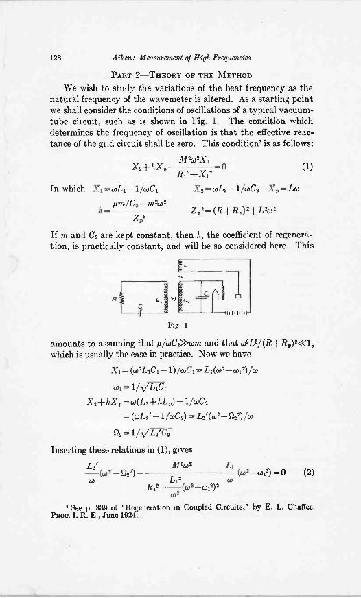
We wish to study the variations of the beat frequency as thenatural frequency of the wavemeter is altered. As a starting pointwe shall consider the conditions of oscillations of a typical vacuum -tube circuit, such as is shown in Fig. 1. The condition whichdetermines the frequency of oscillation is that the effective reac-tance of the grid circuit shall be zero. This condition2 is as follows:
M2,02X1X2-1- h1C, =0 (1)
Ri2+Xi2
In which =win- 1 /WCI X2 = WL2 1 /WC2 Xp = Lco
µm/ C2- m2(02h= Z p2 = (R -I-14)2+ L2w2
Z,2
If m and C2 are kept constant, then h, the coefficient of regenera-tion, is practically constant, and will be so considered here. This
L
LO.Fig. 1
1111111.
amounts to assuming that AlcoC2>>cirm, and that co2L 2 / (R R)2 <<1 ,
which is usually the case in practice. Now we have
X1= (co2L2C2-1)/coCi = Li (co' -co22)/co
col = 1/VL1C1
X2 + IOC p= w(L2-FhL,) - lcoC2
=(coL2' - 11wC2) = 1-2'(,02-5222) w
S/2 = 1A/L2T2
Inserting these relations in (1), gives
L2' M2,02
co(w2-1222)
L12 w(w2-w12) =0 (2)
R12
2
(co 2 w12) 2
W
*See p. 339 of "Regeneration in Coupled Circuits," by E. L. Chaffee.PROC. I. R. E., June 1924.
Aiken: Measurement of High Frequencies 129
Since S12 is a constant it is possible to obtain w as a function ofcol and this relation would yield the desired information. However,the above equation is of the third degree in co2 and of the seconddegree in co12 and a direct treatment leads to extreme compli-cations.
More convenient results can be obtained by solving for (w - a2)as a function of (col -02) and introducing certain well -justifiedapproximations. Equation (2) can be written
L21M20)- (CO 0)1) (CO +0.11)
w(CO 122) (0) + a2)
L12R121-
2-(co col) 2(co +col) 2
Co
Let y=co-0,2 and u=co-w1
=0
coM2co2Liu (1 + -
2 \co )
(3)yL2' (1 +2 =0co
2Ri2+LI2u2 \1+w1/CO
Now assume that 02/co =col/co =1 and call S22= 52 =co
2/1/202LluThen 2L2'Y -0 (4)
R12+4Li2u2
Let X = COI - ft= y -
Eliminating u from (4) givesM2S22L1(y-x)
Lz'y -0 (5)RI2-1-4LL2(y - x) 2
or 4L12L21 (y3 2Y2x+Yx2) (Ri2L12 -M2S22Li)y+M21.22Lix =0.This can be written y2- 2y2x +yx2d-Dy+Ex= 0 (6)In which
Ii121,2' -Msf2214 (712-72)02D= =4 1 12L2' 4
M2S22L1 T2122 .(7)
E= =4L,2L2' 4
130 Aiken: Measurement of High Frequencies
ni2c22
n1= -R1 7-
D -1--B=-4 >u
N/T,T2'
y/27r = (co- 1)/27r is the beat frequency and x127=(coi-U)/21-is the frequency difference between the wavemeter setting and theresonant frequency. E cannot be less than zero but D may bepositive, negative, or zero.
The obtaining of y as a function of x necessitates the solution ofa cubic equation and involves calculations of considerable compli-cation. We shall examine the equation and obtain all the informa-tion we desire without actually solving it.
Let us note that the substitution of -x for x or of -y for y in(6) reduces it to
y3-1-2y2x-f-yx2-1-Dy-Ex=0 (9)
Since (6) and (9) are not identical it follows that the curve y =f (x)is not symmetrical with respect to either the x or y axes. However,the simultaneous substitution of -x for x and -y for y leaves (6)unchanged and hence y =f(x) is symmetrical with respect to theorigin. Equation (6) may be written
Ex-[(y-x)2-1-D1 (10)
y
(8)
Now (y -x)20. Hence if D is positive x/y is always negativeand y =f(x) lies entirely in the second and fourth quadrants andmust either be discontinuous or pass through the origin. A detailedinvestigation shows that the curve is continuous at all points. If Dis negative the curve lies in the first and third quadrant for smallvalues of (y -x)2 and in the second and fourth for values of(y - x)2 which are larger than - D. When x =0 then y3-I-Dy =0by (6). Hence
y=0 or y=±V-D (11)
If DO then y =0 is the only solution, while if D <0 there are threepossible values of y corresponding to x=0, that is, to the resonantsetting of the wavemeter.
Solving (6) for x = F(y) we obtain
x= y-E/2y± VE2/4y2- (E±D) (12)
given by x. -+
Aiken: Measurement of High Frequencies 131
If x is to be real there is imposed upon y the restriction that
y26 E2/4(E±D) (13)
2(E -I -D)
dx E 4y2(E= 1+2-y-2 1 + 1
E2 4y2 (E D) (14)1
E_
If we choose the positive sign in the ambiguity then when y =0,dx/dy = co . This corresponds to x= ± co . If we choose the nega-tive sign, then when y = 0, (14) is an indeterminate form, the eval-uation of which gives dx/dy= - Di E. Hence the slope, at theorigin, of y=f(x) is negative when D> 0, is infinite when D = 0and is positive when D <0. dx/dy is also infinite when 1 -4y2(E-I-D)/E2= O. This corresponds to a maximum value of y.
EY.= ±
2V -K -F -D
Inserting (15) in (12) we obtain the value of x which correspondsto the maximum value of y
2D+Ex.= (16)2 EV--7 FD
We are now in possession of the following information :(a) y =f(x) is not symmetrical with respect to either the x or
the y axes but is symmetrical with respect to the origin.(b) For D> 0, f lies entirely in the second and fourth quadrants.
For D <0, f lies in the first and third quadrants for (y -x)2 ID Iand in the second and fourth for (y -x)2< IDS.
(c) The curve passes through the origin.E2
(d) y is restricted in magnitude by the relation y24(E D)
(e) Within the range of (d) there are two distinct values of xfor every value of y except for y= + E /2V D when the twovalues of x are identical.
(f) The maximum and minimum values of y are given by therelation of (d). The values of x corresponding to these values of y are
2D -FE
2 E D
(15)
132 Aiken: Measurement of High Frequencies
(g) The slope of the curve at the origin is given by
dy -E 72
dx D (n12-7.2)
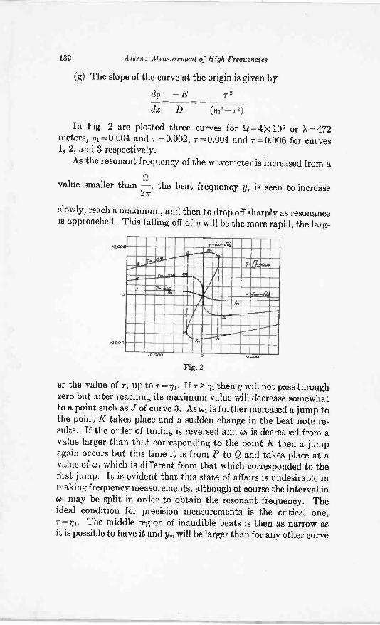
In Fig. 2 are plotted three curves for S2=4 X 10⁶ or X = 472meters, ni= 0.004 and T= 0.002, 7=0.004 and T= 0.006 for curves1, 2, and 3 respectively.
As the resonant frequency of the wavemeter is increased from a11
value smaller than -, the beat frequency y, is seen to increase2r
slowly, reach a maximum, and then to drop off sharply as resonanceis approached. This falling off of y will be the more rapid, the larg-
10,000
0
1,000
r
I 121
r -4.44.r420
,0 000 0
Fig. 2
.4000
er the value of r, up to r = ni. If r> m then y will not pass throughzero but after reaching its maximum value will decrease somewhatto a point such as J of curve 3. As col is further increased a jump tothe point K takes place and a sudden change in the beat note re-sults. If the order of tuning is reversed and col is decreased from avalue larger than that corresponding to the point K then a jumpagain occurs but this time it is from P to Q and takes place at avalue of col which is different from that which corresponded to thefirst jump. It is evident that this state of affairs is undesirable inmaking frequency measurements, although of course the interval incol may be split in order to obtain the resonant frequency. Theideal condition for precision measurements is the critical one,7=n1. The middle region of inaudible beats is then as narrow asit is possible to have it and ym will be larger than for any other curve
Aiken: Measurement of High Frequencies 133
which does not give a discontinuity in the beat frequency. Callingthe value of y, corresponding to r = ni, ymm we have:
ymm = =2 4
(17)
This is directly proportional to the frequency. On the other hand
Yfrimis dependent only on the quantity in which is, for many
coils, almost independent of frequency over a considerable range.
In the case citedYmm
= 0.001 or 0.1 per cent and the approximations
St WI-=-=1 which were introduced into the original equations, are
co co
well justified. It is evident that the method is better adapted to
the higher frequencies since the value of - must be in the audible27
range, and if the frequency under measurement is low, y, may betoo large a fraction of St. However, the range of applicability maybe extended several octaves by adjusting the auxiliary oscillator tozero beats with a harmonic of the oscillator which is being meas-ured. If one of the higher harmonics is thus employed it may benecessary to insert the telephones in the circuit of the oscillatorunder measurement in order that the beat note may be audiblewithout excessive amplification. Frequencies outside of the rangeof the wavemeter may also be determined by employing theharmonics of one or both oscillators.
If the two oscillators are not exactly in resonance a certainerror will be introduced into the determination of the wavelength.
Suppose that the frequencyS23-
of the auxiliary oscillator is slightly2r
SZ
lower than -, the frequency which is being determined. If the in -27
terval ab, in Fig. 3, represents the magnitude of the minimum fre-quency of audibility, then when the wavemeter is absent the beat
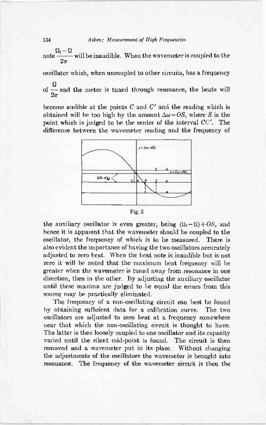
134 Atken: Measurement of High Frequencies
note% - will be inaudible. When the wavemeter is coupled to the27
oscillator which, when uncoupled to other circuits, has a frequency
SZ
of - and the meter is tuned through resonance, the beats will27
become audible at the points C and C' and the reading which isobtained will be too high by the amount Aco = OS, where S is thepoint which is judged to be the center of the interval CC'. Thedifference between the wavemeter reading and the frequency of
-1b)
3 C
Fig. 3
the auxiliary oscillator is even greater, being (S23 -12)-1-0S, andhence it is apparent that the wavemeter should be coupled to theoscillator, the frequency of which is to be measured. There isalso evident the importance of having the two oscillators accuratelyadjusted to zero beat. When the beat note is inaudible but is notzero it will be noted that the maximum beat frequency will begreater when the wavemeter is tuned away from resonance in onedirection, then in the other. By adjusting the auxiliary oscillatoruntil these maxima are judged to be equal the errors from thissource may be practically eliminated.
The frequency of a non -oscillating circuit can best be foundby obtaining sufficient data for a calibration curve. The twooscillators are adjusted to zero beat at a frequency somewherenear that which the non -oscillating circuit is thought to have.The latter is then loosely coupled to one oscillator and its capacityvaried until the silent mid -point is found. The circuit is thenremoved and a wavemeter put in its place. Without changingthe adjustments of the oscillators the wavemeter is brought intoresonance. The frequency of the wavemeter circuit is then the
Aiken: Measurement of High Frequencies 135
same as that of the circuit under measurement. By obtainingseveral such points a calibration curve can be drawn and the fre-quency corresponding to any given condenser setting may beobtained by interpolation. If the circuit elements are invariablean auxiliary condenser may be added and two or three pointsobtained. If these points are properly chosen a fairly accurateextrapolation may be made to find the frequency which is asso-ciated with the circuit when the auxiliary condenser is removed.
uinThe relation r = 2,1/ Y ior M =-2Vy.RiL2 (15a)
suggests a possible method for the measurement of the coefficientof coupling or the mutual inductance. If the mutual inductancebetween two circuits is to be measured, one of them, the in-ductance of which is known, may be connected to a vacuum tubeand made to function as one of the two oscillating circuits requiredto obtain zero beats while the other replaces the wavemetercircuit in the foregoing discussions. If the various circuit constants
y,are such that - lies within the audible range it may be measured
2ron a frequency meter of the resonance bridge or other suitabletype. Then if R1, L? and SI are known, M may be determined from(15a). The variation of y with x in the neighborhood of y, issmall and hence there should be no difficulty involved in setting xso as to obtain a value of y which is very near the maximum.RI can be found by any of the standard methods for the deter-mination of resistance at high frequencies. St must be determinedby means of a wavemeter as in the above. Since y R1 and L2enter under the radical sign the per cent error introduced intothe value of M by a small error in any one of these quantitieswill be half the per cent error in that quantity.
In case a frequency meter is not available y, may be adjustedto zero beat with a tuning fork by inserting a variable resistance inthe circuit (1) and changing R1 until y, has the proper value.
Another method which might suggest itself as applicable incase there is no frequency meter to be had is that of bringing yinto zero beat with a tuning fork by varying x. This adjustmentis possible for four values of x provided that the frequency of thefork is less than y,,. Since y now differs from y, the relation
136 Aiken: Measurement of High Frequencies
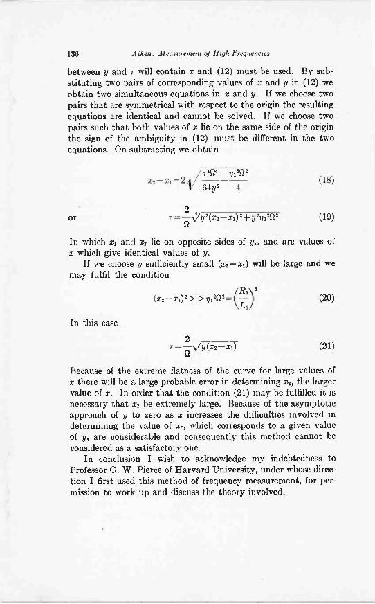
between y and r will contain x and (12) must be used. By sub-stituting two pairs of corresponding values of x and y in (12) weobtain two simultaneous equations in x and y. If we choose twopairs that are symmetrical with respect to the origin the resultingequations are identical and cannot be solved. If we choose twopairs such that both values of x lie on the same side of the originthe sign of the ambiguity in (12) must be different in the twoequations. On subtracting we obtain
or
x2- = 2 /r424ni2S22
64y2 4
2= _vy2(x2_ x1)2±y2...0121-22
(18)
(19)
In which x1 and x2 lie on opposite sides of y, and are values ofx which give identical values of y.
If we choose y sufficiently small (x2-x1) will be large and wemay fulfil the condition
2(x2-x1) 2 > > n1202 = (11) (20)Li
In this case
2r= -Vy(x2- x1) (21)
Because of the extreme flatness of the curve for large values ofx there will be a large probable error in determining x2, the largervalue of x. In order that the condition (21) may be fulfilled it isnecessary that x2 be extremely large. Because of the asymptoticapproach of y to zero as x increases the difficulties involved indetermining the value of x2, which corresponds to a given valueof y, are considerable and consequently this method cannot beconsidered as a satisfactory one.
In conclusion I wish to acknowledge my indebtedness toProfessor G. W. Pierce of Harvard University, under whose direc-tion I first used this method of frequency measurement, for per-mission to work up and discuss the theory involved.
PRECISION DETERMINATION OF FREQUENCY*
BY
J. W. HORTON AND W. A. MARRISON(Bell Telephone Laboratories, New York City)
Summary-The relations between frequency and time are such that it isdesirable to refer them to a common standard. Reference standards, both of timeand of frequency, are characterized by the requirement that their rates shall beno constant that the total number of variations executed in a time of known dura-tion may be taken as a measure of the rate over shorter intervals of time. Frequencystandards have the further requirement that the form of their variations and theIrder of magnitude of their rates shall be suitable for comparison with the wavesused in electrical communication.
Two different types of standard which meet these requirements are described.One consists of a regenerative vacuum -tube circuit, the frequency of which is deter-mined by the mechanical properties of a tuning fork. The other is a regenerativecircuit controlled by a piezo-active crystal. Means are provided, in the case of eachstandard, whereby the recurrent cycles may be counted by a mechanism havingthe form of a clock, the rate of which is a measure of the frequency of the referencestandard.
Data taken over a period of several years with a fork -controlled circuit showthat, under normal conditions, its rate may be relied upon to two parts in one mil-lion. Data taken over a much shorter time with crystal controlled oscillators indi-cate that they are
WHEN we speak of the frequency of a wave or, in fact,when we use the word frequency in any connection, wemean, in general, the number of times a periodic oc-
currence takes place within a given interval of time. Consequentlythe frequency of a recurrent phenomenon is the reciprocal of thetime interval required for the variation to pass through one cycleprovided the duration of any given cycle is identical with that ofany other, or, in other words, that the variation has a constantfrequency. Since, therefore, frequency may be expressed com-pletely in terms of time, it is neither necessary nor desirable tohave any fundamental standard of frequency other than theaccepted standard time interval.
The present standard of time is, of course, the sidereal day,which is the time required for the earth to make one completerevolution in space. A succession of sidereal days, therefore,constitutes a recurrent phenomenon the duration of any cycle ofwhich is, by definition, equal in time to the duration of any other
Original Manuscript Received by the Institute, December 6, 1927.* Paper read at meeting of the International Union of Scientific Radio
Telegraphy, Washington, Oct. 13, 1927.
137
138 Horton and Morrison: Determination of Frequency
cycle. In other words, the variation has the essential character-istics required of a standard of frequency. The mean solar day,in terms of which all measurements of time are expressed, mustbe considered as a practical standard the determination of whichis made in terms of the sidereal day.
There is a unique difference between a standard of time-orfrequencyand standards of most other quantities. For example,the standard unit of mass or the standard unit of length may begiven physical embodiments and may be put in a safe where theiridentity will be preserved over extended periods. Unlike a massor a length, an interval of time cannot of itself be preserved norcan it readily be given a physical embodiment which by virtueof its great constancy may be used as a fundamental standard.At present, therefore, all precision measurements of time must bereferred directly to the rate of the earth's rotation.
Having once concluded that the fundamental standard of timeis, ex officio, the fundamental standard of frequency, there remainssimply the problem of comparing the rate of any periodic variationwhich is to be measured with the rate of the earth's rotation.
If there were available only the periodic phenomenon of un-known rate and the intervals defined by the earth's rotation, itwould be necessary that the unknown phenomenon maintain itsrate unchanged throughout an entire interval covered by onerotation of the earth. In this case the measurement would consistin counting the number of times the unknown variation repeateditself during the interval. Due, however, to the availability ofmeans for accurately defining time intervals less than the siderealday to the required precision, it is, of course, unnecessary tomaintain the rate of the variation to be measured over the longerinterval. When we recognize that any means used for evaluatingthe time of short intervals is itself executing periodic variationsof equal duration, we realize that it is a secondary standard offrequency as well as a secondary standard of time. Thus theRiefler clocks at the National Bureau of Standards and at theU. S. Naval Observatory become our most practical workingstandards of frequency. In terms of the oscillations of theirpendulums their frequency may be said to be unity when referredto the second.
A secondary standard such as a high grade seconds pendulumis unsuited to the actual determination of the frequency of suchvariations as are of interest in electrical communication, both
.411. 1 11 41111,4141101Mber..
Horton and Marrison: Determination of Frequency 139
because of the excessively high ratio between the rates of theoccurrences to be compared and because, in its usual form, themotion of a clock pendulum is not well suited for comparison withelectrical variations. It is desirable, therefore, as the first step inthe precision measurement of the frequencies of electric waves, toprovide a suitable reference standard. The requirements of sucha standard are that its rate should be of the same order of magni-tude as the rates to be measured, that the form of the variationwhich it controls should be suitable for convenient comparisonwith the variations to be measured, and, finally, that its rate shallbe sufficiently constant so that the total number of variationswhich it executes in a time of such duration that it may be definedwith high precision may be taken as the rate of the variation overshorter intervals of time. This last requirement again emphasizesthe inherent similarity between secondary standards of frequencyand secondary standards of time. For convenience, it should alsobe possible to adjust the rate of the frequency standard to someprescribed value within such limits that the error may be neglectedin the majority of measurements.
ORIGINAL EQUIPMENT
A secondary standard having the characteristics mentionedabove was described several years ago by the authors of thepresent paper in collaboration with Mr. N. H. Ricker. Thisstandard consists of a 100 -cycle tuning fork maintained in vibra-tion by an amplifier regeneratively connected through the forkby electromagnetic coupling. Means are provided for obtainingfrom the electrical portion of the resulting oscillating system asinusoidal alternating current the frequency of which is constantto high precision. Standards of this general type are beingextensively used, as will be seen by referring to the bibliography.A brief survey of the present status of this 100 -cycle standard isof interest not only because of the improvement in its performancesince the original report was presented, but also because theexperience which has been gained from its use has been of valuein the development of standards of still greater utility.
The fork which was described in the paper already referredto ran continuously from April, 1923, to May, 1927, except forfour intervals totalling about three days. Of these interruptionstwo were from accidental causes and two for the purpose of makingminor changes in the system. Throughout this entire period the
140 Horton and Marrieon: Determination of Frequency
temperature of the fork, as maintained by its thermostaticallycontrolled water bath, was held at approximately the value for
which its rate is 100 cycles. Since the temperature coefficient of
frequency for the particular fork in question is 0.0109 per cent
per degree Centigrade, it is necessary to keep the temperature
to within 0.01 deg. C. of the prescribed value in order that the
rate shall be correct to one part in a million. It has been found
that the temperature coefficient, instead of being a detriment,
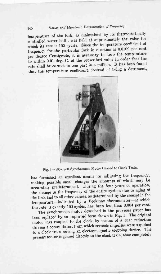
Fig. 1 -100 -cycle Synchronous Motor Geared to Clock Train.
has furnished an excellent means for adjusting the frequency,making possible small changes the amounts of which may be
accurately predetermined. During the four years of operation,the change in the frequency of the entire system due to aging of
the fork and to all other causes, as determined by the change in thetemperature-indicated by a Beekman thermometer-at whichthe rate is exactly 100 cycles, has been less than 0.004 per cent.
The synchronous motor described in the previous paper has
been replaced by an improved form shown in Fig. 1. The original
motor was coupled to the clock by means of a gear reduction
driving a commutator, from which seconds impulses were supplied
to a clock train having an electromagnetic stepping device. The
present motor is geared directly to the clock train, thus completely
Horton and Morrison: Determination of Precision Frequency 141
avoiding errors due to the mechanism. In spite of the lack ofconfidence expressed by many people in the impulse type ofsynchronous motor, both of those mentioned have been found togive entirely satisfactory operation over long periods of time. Infact, the only occasions on which the motors have ever stoppedin service have been those on which power was taken off someportion of the system.
During tests on this frequency standard, it was found that itconstituted a far more reliable timekeeper than the electricallymaintained pendulum clock which was used to obtain the dataalready published. The pendulum clock was, therefore, dispensed
S8S
AuGuS1
-'----4
'1'-'7"---77jT------
3 4 5 7 65 03 Y a A 6 4 7 6 410 h 477374 tS X 1116!51331DAYS Or 140114.
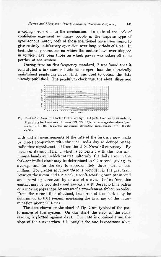
Fig. 2-Daily Error in Clock Controlled by 100 -Cycle Frequency Standard.Mean rate for three month period 99.99991 cycles; average deviation frommean rate 0.00016 cycles; maximum deviation from mean rate 0.00067cycles.
with and all measurements of the rate of the fork are now madeby direct comparison with the mean solar day as defined by theradio time signals sent out from the U. S. Naval Observatory. Bymeans of its second hand, which is concentric with the hour andminute hands and which rotates uniformly, the daily error in thefork -controlled clock may be determined to 0.2 second, giving itsaverage rate for the day to approximately three parts in onemillion. For greater accuracy there is provided, in the gear trainbetween the motor and the clock, a shaft rotating once per secondand operating a contact by means of a cam. Pulses from thiscontact may be recorded simultaneously with the radio time pulseson a moving paper tape by means of a two -element siphon recorder.From the record thus obtained, the error of the clock may bedetermined to 0.01 second, increasing the accuracy of the deter-mination about 20 times.
The data shown by the chart of Fig. 2 are typical of the per-formance of this system. On this chart the error in the clockreading is plotted against days. The rate is obtained from theslope of the curve; when it is straight the rate is constant; when
142 Horton and Morrison: Determination of Frequency
it is horizontal the rate is exactly 100 cycles. Attention is callednot only to the constancy of the rate, which at no time duringthe period covered by this record departed more than 0.0007per cent from the mean rate, but also to the precision with whichthe system was adjusted to the desired absolute value.
A method for the comparison of high frequencies with the100 -cycle standard is also outlined in the previous paper. Thismethod involves the use of harmonic producers and of harmonicselecting networks. By repeated harmonic production andselection it is possible to obtain any multiple of the fundamentalfrequency to a limit determined by the care taken. Theoreticallythe process may be extended indefinitely, but practically thereare difficulties in going beyond two or three stages. These diffi-culties arise from small irregularities in the frequency or in theamplitude of the current in the initial stages of the system, allof which result in frequency irregularities in the final wave. Whilethese may be entirely negligible in the wave in which they origi-nate, they are enormously magnified in subsequent stages. Withordinary care it is feasible to obtain from the 100 -cycle standardcurrent a current having a frequency of 100,000 cycles per secondor even higher. By the use of a cathode ray oscillograph, anindependent oscillator may be adjusted so that its frequency isan exact multiple of the frequency of the current thus obtained.This process may be repeated by successive stages up to the limitof the oscillograph tube.
The system, therefore, contains three essential elements:(1) The regeneratively driven fork constitutes a source of alter-nating current, the frequency of which is 100 cycles to a veryhigh precision. (2) The synchronous motor and the gear trainof the clock constitute a rate reducing mechanism having a ratioof approximately ten million to one. (3) The harmonic producersystem and the cathode ray oscillographs may be operated so asto increase the frequency in the ratio of several thousand to one. Itis, therefore, practicable by means of this system to determine thefrequency of an electric wave, using the mean solar day as a stan-dard, when the ratio between them does not exceed about 1011.
PRESENT EQUIPMENT
At the time the development of the 100 -cycle standard wasundertaken, the frequency range over which measurements wererequired to high precision did not exceed several hundred thousandcycles per second. For this work the frequency chosen for the
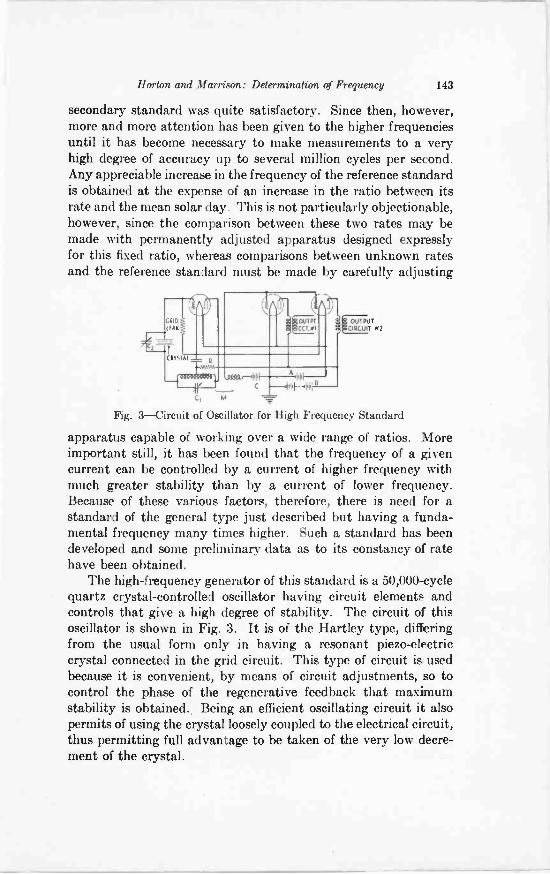
Horton and Morrison: Determination of Frequency 143
secondary standard was quite satisfactory. Since then, however,more and more attention has been given to the higher frequenciesuntil it has become necessary to make measurements to a veryhigh degree of accuracy up to several million cycles per second.Any appreciable increase in the frequency of the reference standardis obtained at the expense of an increase in the ratio between itsrate and the mean solar day. This is not particularly objectionable,however, since the comparison between these two rates may bemade with permanently adjusted apparatus designed expresslyfor this fixed ratio, whereas comparisons between unknown ratesand the reference standard must be made by carefully adjusting
A1.1
ill+ 41111
M
OUTPUTCIRCUIT N2
Fig. 3-Circuit of Oscillator for High Frequency Standard
apparatus caciable of working over a wide range of ratios. Moreimportant still, it has been found that the frequency of a givencurrent can be controlled by a current of higher frequency withmuch greater stability than by a current of lower frequency.Because of these various factors, therefore, there is need for astandard of the general type just described but having a funda-mental frequency many times higher. Such a standard has beendeveloped and some preliminary data as to its constancy of ratehave been obtained.
The high -frequency generator of this standard is a 50,000 -cyclequartz crystal -controlled oscillator having circuit elements andcontrols that give a high degree of stability. The circuit of thisoscillator is shown in Fig. 3. It is of the Hartley type, differingfrom the usual form only in having a resonant piezo-electriccrystal connected in the grid circuit. This type of circuit is usedbecause it is convenient, by means of circuit adjustments, so tocontrol the phase of the regenerative feedback that maximumstability is obtained.. Being an efficient oscillating circuit it alsopermits of using the crystal loosely coupled to the electrical circuit,thus permitting full advantage to be taken of the very low decre-ment of the crystal.
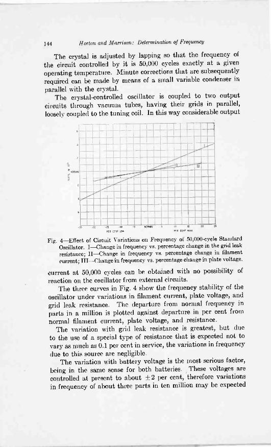
144 Horton and Morrison: Determination of Frequency
The crystal is adjusted by lapping so that the frequency ofthe circuit controlled by it is 50,000 cycles exactly at a givenoperating temperature. Minute corrections that are subsequentlyrequired can be made by means of a small variable condenser in
parallel with the crystal.The crystal -controlled oscillator is coupled to two output
circuits through vacuum tubes, having their grids in parallel,loosely coupled to the tuning coil. In this way considerable output
I
I7 ;LI ;
---.-...
111
_4.
MJ -ZO -15 AP -5 .0166 5 q 6 65 iiKR CENT LOW PEN aNt NON
Fig. 4-Effect of Circuit Variations on Frequency of 50,000-cycle StandardOscillator. I-Change in frequency vs. percentage change in the grid leakresistance; II-Change in frequency vs. percentage change in filamentcurrent; III-Change in frequency vs. percentage change in plate voltage.
current at 50,000 cycles can be obtained with no possibility ofreaction on the oscillator from external circuits.
The three curves in Fig. 4 show the frequency stability of theoscillator under variations in filament current, plate voltage, andgrid leak resistance. The departure from normal frequency inparts in a million is plotted against departure in per cent fromnormal filament current, plate voltage, and resistance.
The variation with grid leak resistance is greatest, but dueto the use of a special type of resistance that is expected not tovary as much as 0.1 per cent in service, the variations in frequencydue to this source are negligible.
The variation with battery voltage is the most serious factor,being in the same sense for both batteries. These voltages arecontrolled at present to about ±2 per cent, therefore variationsin frequency of about three parts in ten million may be expected
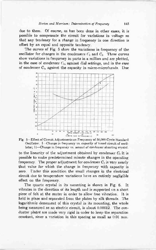
Horton and Marrison: Determination of Frequency 145
due to them. Of course, as has been done in other cases, it ispossible to compensate the circuit for variations in voltage sothat any tendency for a change in frequency in one direction isoffset by an equal and opposite tendency.
The curves of Fig. 5 show the variations in frequency of theoscillator for changes in the condensers C1 and C2. These curvesshow variations in frequency in parts in a million and are plotted,in the case of condenser C2, against dial settings, and in the caseof condenser C1, against the capacity in micro-microfarads. Due
60
14
2.
14
66
IIIIIIIIIIIIIIIIIII1NIMIMMINIMINIMPAMMI11111101151111EMPAIRM1010IINIMMII4111111M12111IMMII111M101110111111MMIIIMIEMUNIMENIMIMIM INEEMENIIIM111=16111111111111MEM
20 10 40 40 240 0 00 90 .00 00 60 00 14046026 CArACIT224144 (CuRv2
0 r0 Ao 60 00 100520221244 COW Ser2,14432Cu04( 2)
Fig. 5-Effect of Circuit Adjustments on Frequency of 50,000 -Cycle StandardOscillator. I-Change in frequency vs. capacity of tuned circuit of oscil-lator; II-Change in frequency vs. second of condenser shunting crystal.
to the linearity of the adjustment obtained by condenser C2 it ispossible to make predetermined minute changes in the operatingfrequency. The proper adjustment for condenser C2 is very nearlythat value for which the change in frequency with capacity iszero. Under this condition the small changes in the electricalcircuit due to temperature variations have an entirely negligibleeffect on the frequency.
The quartz crystal in its mounting is shown in Fig. 6. Itvibrates in the direction of its length and is supported on a shortpiece of felt at the center in order to allow free vibration. It isheld in place and separated from the plates by silk threads. Thelogarithmic decrement of this crystal in its mounting, the wholebeing measured as an electric circuit, is about 0.00012. The con-ductor plated are made very rigid in order to keep the separationconstant, since a variation in this spacing as small as 0.01 mm.
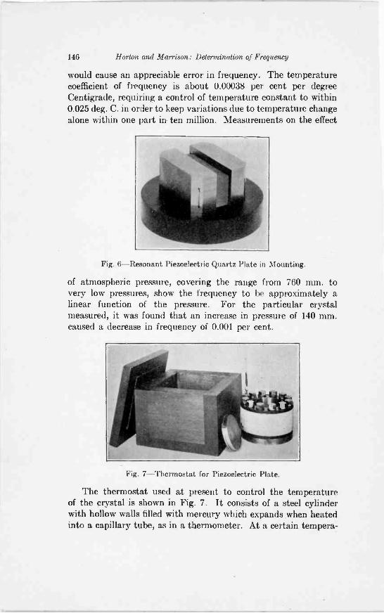
146 Horton and Marrieon: Determination of Frequency
would cause an appreciable error in frequency. The temperaturecoefficient of frequency is about 0.00038 per cent per degreeCentigrade, requiring a control of temperature constant to within0.025 deg. C. in order to keep variations due to temperature changealone within one part in ten million. Measurements on the effect
Fig. 6-Resonant Piezoelectric Quartz Plate in Mounting.
of atmospheric pressure, covering the range from 760 mm. tovery low pressures, show the frequency to be approximately alinear function of the pressure. For the particular crystalmeasured, it was found that an increase in pressure of 140 mm.caused a decrease in frequency of 0.001 per cent.
Fig. 7-Thermostat for Piezoelectric Plate.
The thermostat used at present to control the temperatureof the crystal is shown in Fig. 7. It consists of a steel cylinderwith hollow walls filled with mercury which expands when heatedinto a capillary tube, as in a thermometer. At a certain tempera-
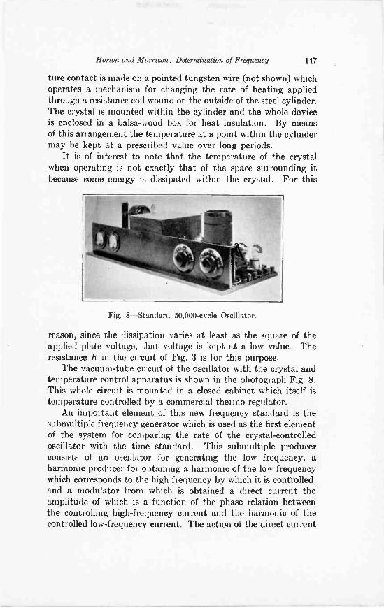
Horton and Morrison: Determination of Frequency 147
ture contact is made on a pointed tungsten wire (not shown) whichoperates a mechanism for changing the rate of heating appliedthrough a resistance coil wound on the outside of the steel cylinder.The crystal is mounted within the cylinder and the whole deviceis enclosed in a balsa -wood box for heat insulation. By meansof this arrangement the temperature at a point within the cylindermay be kept at a prescribed value over long periods.
It is of interest to note that the temperature of the crystalwhen operating is not exactly that of the space surrounding itbecause some energy is dissipated within the crystal. For this
Fig. 8-Standard 50,000 -cycle Oscillator.
reason, since the dissipation varies at least as the square of theapplied plate voltage, that voltage is kept at a low value. Theresistance R in the circuit of Fig. 3 is for this purpose.
The vacuum -tube circuit of the oscillator with the crystal andtemperature control apparatus is shown in the photograph Fig. 8.This whole circuit is mounted in a closed cabinet which itself istemperature controlled by a commercial thermo-regulator.
An important element of this new frequency standard is thesubmultiple frequency generator which is used as the first elementof the system for comparing the rate of the crystal -controlledoscillator with the time standard. This submultiple producerconsists of an oscillator for generating the low frequency, aharmonic producer for obtaining a harmonic of the low frequencywhich corresponds to the high frequency by which it is controlled,and a modulator from which is obtained a direct current theamplitude of which is a function of the phase relation betweenthe controlling high -frequency current and the harmonic of thecontrolled low -frequency current. The action of the direct current
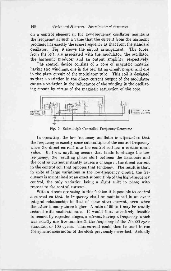
148 Horton and Morrison: Determination of Frequency
on a control element in the low -frequency oscillator maintainsthe frequency at such a value that the current from the harmonicproducer has exactly the same frequency as that from the standardoscillator. Fig. 9 shows the circuit arrangement. The tubes,from the left, are associated with the modulator, the oscillator,the harmonic producer and an output amplifier, respectively.
The control device consists of a core of magnetic materialhaving two windings, one in the oscillating circuit proper and onein the plate circuit of the modulator tube. This coil is designedso that a variation in the direct current output of the modulatorcauses a variation in the inductance of the winding in the oscillat-ing circuit by virtue of the magnetic saturation of the core.
INPUT OFNIGH FPFQ
cC,
A4
OF CON-TROLLED
Fig. 9-Subnultiple Controlled Frequency Generator
In operating, the low -frequency oscillator is adjusted so thatthe frequency is exactly some submultiple of the control frequencywhen the direct current into the control coil has a certain meanvalue. If, then, anything occurs that tends to change the lowfrequency, the resulting phase shift between the harmonic andthe control current instantly causes a change in the direct currentin the control coil that opposes that tendency. The result is that,in spite of large variations in the low -frequency circuit, the fre-quency is maintained at an exact submultiple of the high -frequencycontrol, the only variation being a slight shift in phase withrespect to the control current.
With a circuit operating in this fashion it is possible to controla current so that its frequency shall be maintained in an exactintegral relationship to that of some other current, even whenthe latter is many times higher. A ratio of 50 to 1 may be readilysecured with moderate care. It would thus be entirely feasibleto secure, by repeated stages, a current having a frequency whichwas exactly one five -hundredth the frequency of the 50,000 -cyclestandard, or 100 cycles. This current could then be used to runthe synchronous motor of the clock previously described. Actually
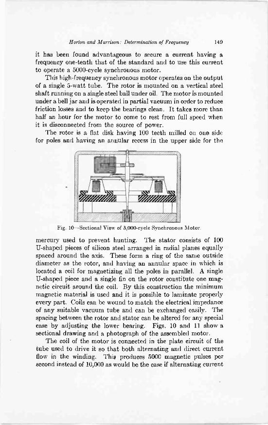
Horton and Morrison: Determination of Frequency 149
it has been found advantageous to secure a current having afrequency one -tenth that of the standard and to use this currentto operate a 5000 -cycle synchronous motor.
This high -frequency synchronous motor operates on the outputof a single 5 -watt tube. The rotor is mounted on a vertical steelshaft running on a single steel ball under oil. The motor is mountedunder a bell jar and is operated in partial vacuum in order to reducefriction losses and to keep the bearings clean. It takes more thanhalf an hour for the motor to come to rest from full speed whenit is disconnected from the source of power.
The rotor is a flat disk having 100 teeth milled on one sidefor poles and having an annular recess in the upper side for the
,Mkki%,\.. .N111111111111111.11t NMS. N.
ivy/ ,k
,14111111111\\r
Fig. 10-Sectional View of 5,000 -cycle Synchronous Motor.
mercury used to prevent hunting. The stator consists of 100U-shaped pieces of silicon steel arranged in radial planes equallyspaced around the axis. These form a ring of the same outsidediameter as the rotor, and having an annular space in which islocated a coil for magnetizing all the poles in parallel. A singleU-shaped piece and a single fin on the rotor constitute one mag-netic circuit around the coil. By this construction the minimummagnetic material is used and it is possible to laminate properlyevery part. Coils can be wound to match the electrical impedanceof any suitable vacuum tube and can be exchanged easily. Thespacing between the rotor and stator can be altered for any specialcase by adjusting the lower bearing. Figs. 10 and 11 show asectional drawing and a photograph of the assembled motor.
The coil of the motor is connected in the plate circuit of thetube used to drive it so that both alternating and direct currentflow in the winding. This produces 5000 magnetic pulses persecond instead of 10,000 as would be the case if alternating current
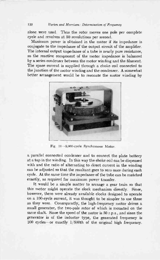
150 Horton and Morrison: Determination of Frequency
alone were used. Thus the rotor moves one pole per completecycle and revolves at 50 revolutions per second.
Maximum power is obtained in the motor if its impedance isconjugate to the impedance of the output circuit of the amplifier.The internal output impedance of a tube is nearly pure resistance,so the reactive component of the motor impedance is balancedby a series condenser between the motor winding and the filament.The space current is supplied through a choke coil connected tothe junction of the motor winding and the condenser. A somewhatbetter arrangement would be to resonate the motor winding by
Fig. 11 -5,000 -cycle Synchronous Motor.
a parallel connected condenser and to connect the plate batteryat a tap in the winding. In this way the choke coil can be dispensedwith and the ratio of alternating to direct current in the windingcan be adjusted so that the resultant goes to zero once during eachcycle. At the same time the impedance of the tube can be matchedexactly, as required for maximum power transfer.
It would be a simple matter to arrange a gear train so thatthis motor might operate the clock mechanism directly. Since,however, there were already available clocks designed to operateon a 100 -cycle current, it was thought to be simpler to use theseas they were. Consequently, the high -frequency motor drives asmall generator, the two -pole rotor of which is mounted on thesame shaft. Since the speed of the motor is 50 r.p.s., and since thegenerator is of the inductor type, the generated frequency is100 cycles-or exactly 1/500th of the original high frequency.
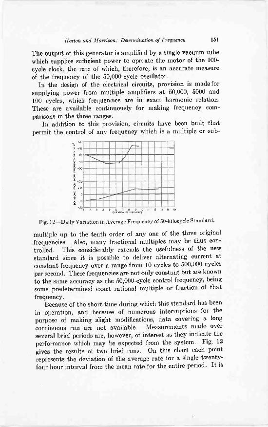
Horton and Morrison: Determination of Frequency 151
The output of this generator is amplified by a single vacuum tubewhich supplies sufficient power to operate the motor of the 100 -cycle clock, the rate of which, therefore, is an accurate measureof the frequency of the 50,000 -cycle oscillator.
In the design of the electrical circuits, provision is made forsupplying power from multiple amplifiers at 50,000, 5000 and100 cycles, which frequencies are in exact harmonic relation.These are available continuously for making frequency com-parisons in the three ranges.
In addition to this provision, circuits have been built thatpermit the control of any frequency which is a multiple or sub-
*"10
/.1
-10
I2.
°
1 wI 5 4 7 8 f 10 11 IN 13 11
OvIADON a TEST Mrs
Fig. 12-Daily Variation in Average Frequency of 50 -kilocycle Standard.
multiple up to the tenth order of any one of the three original
frequencies. Also, many fractional multiples may be thus con-trolled. This considerably extends the usefulness of the newstandard since it is possible to deliver alternating current atconstant frequency over a range from 10 cycles to 500,000 cycles
per second. These frequencies are not only constant but are knownto the same accuracy as the 50,000 -cycle control frequency, being
some predetermined exact rational multiple or fraction of thatfrequency.
Because of the short time during which this standard has been
in operation, and because of numerous interruptions for thepurpose of making slight modifications, data covering a longcontinuous run are not available. Measurements made overseveral brief periods are, however, of interest as they indicate theperformance which may be expected from the system. Fig. 12gives the results of two brief runs. On this chart each pointrepresents the deviation of the average rate for a single twenty-four hour interval from the mean rate for the entire period. It is
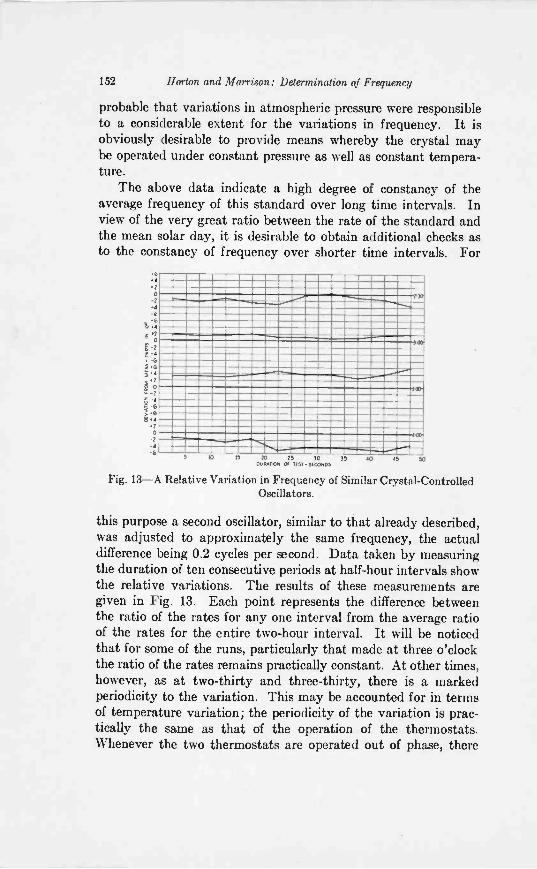
152 Horton and Marrison: Determination of Frequency
probable that variations in atmospheric pressure were responsibleto a considerable extent for the variations in frequency. It isobviously desirable to provide means whereby the crystal maybe operated under constant pressure as well as constant tempera-ture.
The above data indicate a high degree of constancy of theaverage frequency of this standard over long time intervals. Inview of the very great ratio between the rate of the standard andthe mean solar day, it is desirable to obtain additional checks asto the constancy of frequency over shorter time intervals. For
6 4 I
0
66
;
4
:'I I
0
6
SOY
330
p0A-11=1
10 15 70 5 30 30 40031RAT15.1 Of Mt. SECOND3
-"--15 50
Fig. 13-A Relative Variation in Frequency of Similar Crystal -ControlledOscillators.
this purpose a second oscillator, similar to that already described,was adjusted to approximately the same frequency, the actualdifference being 0.2 cycles per second. Data taken by measuringthe duration of ten consecutive periods at half-hour intervals showthe relative variations. The results of these measurements aregiven in Fig. 13. Each point represents the difference betweenthe ratio of the rates for any one interval from the average ratioof the rates for the entire two-hour interval. It will be noticedthat for some of the runs, particularly that made at three o'clockthe ratio of the rates remains practically constant. At other times,however, as at two -thirty and three -thirty, there is a markedperiodicity to the variation. This may be accounted for in termsof temperature variation; the periodicity of the variation is prac-tically the same as that of the operation of the thermostats.Whenever the two thermostats are operated out of phase, there
Horton and Marrison: Determination of Frequency 153
is a noticeable change in the ratio of the rates; whenever they areoperated in phase, their rates remain practically constant.
In view of the fact that the accuracy to which a frequency maybe defined depends on its constancy, on the precision of comparingits rate with the rate of the earth's rotation, and on the accuracyto which the latter rate can be determined, it seems reasonable,in view of the above data, to expect that in the near future itwill be possible to define a frequency at any instant to an absoluteaccuracy of at least one part in ten million.
It has not been:unusual to determine frequency in terms ofsome other quantity such as the acceleration due to gravity, thevelocity of light, or the product of inductance and capacity. Theseare, of course, indirect measurements because each of the otherquantities must first be defined in terms of time. In view of thepresent accuracy obtainable in the measurement of frequency,however, it is now possible to invert the procedure and measuresome of these other physical quantities in terms of frequencywith an accuracy heretofore unattainable.
BIBLIOGRAPHYNo attempt is made in this bibliography to mention all of the contributions
relating to the art of frequency measurements. The attempt has been ratherto pick out a few papers which describe in a broad way various importantphases of the problem. In most cases each of these is accompanied by a fairlyextensive bibliography.
Use of Tuning Forks in Constant Frequency GeneratorsD. W. Dye, The Valve Maintained Tuning Fork as a Precision Time
Standard; Proc. Roy Soc. London, 103A, p. 241, May, 1923.J. W. Horton, N. H. Ricker, W. A. Marrison; Frequency Measurement in
Electrical Communication; Trans. A. I. E. E., 42, p. 730, 1923.J. G. Ferguson, A Clock Controlled Tuning Fork as a Source of Coatant
Frequency; B. S. T. J., 3, p. 145, January, 1924.A. B. Wood, J. M. Ford, The Phonic Chronometer; J1. Sci. Inst., 1,
p. 161, March, 1924.A. B. Wood, Electrically Maintained Tuning Forks-Some Factors
Affecting Frequency; J1. Sci. Inst., 1, p. 335, August, 1924.T. G. Hodgkinson, Valve Maintained Tuning Fork without Condensers;
Phys. Soc. London Proc.; 38, p. 24, December, 1925Elias Klein, Glenn F. Rouse, Methods for Exciting and for Calibrating
Tuning Forks; J.O.S.A. & R.S.I., 14, p. 263, March. 1927.Use of Piezoelectric Plates as Frequency Standards
W. G. Cady, The Piezoelectric Resonator; PROC. I. R. E., 10, p. 83, April,1922.
G. W. Pierce, Piezoelectric Crystal Resonators and Crystal OscillatorsApplied to the Precision Calibration of Wavemeters; Proc. Am. Acad. ofArts and Sci. 59, p. 81, October, 1923.
J. W. Horton, Vacuum Tube Oscillators-A Graphical Method ofAnalysis; B. S. T. J., 3, p. 508, July, 1924.
D. W. Dye, Piezoelectric Quartz Resonator and Equivalent ElectricalCircuit; Phys. Soc. Proc., 38, p. 399, August, 1926.
154 Horton and Marrison: Determination of Frequency
Correlation of Frequency Standards with Standard TimeE. A. Eckhardt, J. C. Karcher. M. Keiser; Electron Tube Tuning -Fork
Drive; J.O.S.A. & R.S.I., 6, p. 949, November. 1922.D. W. Dye. The Valve Maintained Tuning Fork as a Precision Time
Standard; loc. cit.M. Mercier, New Method of Determination of Period of High Frequency
Electric Oscillations; Ann. de phys.. 19, p. 248, 1923.J. W. Horton, N. H. Ricker, W. A. Marrison; Frequency Measurement
in Electrical Communication; loc. cit.J. G. Ferguson, A Clock Controlled Tuning Fork as a Source of Constant
Frequency; loc. cit.G. Ferrie, R. Jouaust, The Use of Photoelectric Cells in the Observation
and Maintenance of Astronomical Pendulums; Comptes Rendus, 180, p. 1145,April, 1925.
Ehas Klein, Glenn F. Rouse; Methods for Exciting and for CalibratingTuning Forks; loc. cit.
R. H. Worrall, R. B. Owens, The Navy's Primary Frequency Standard;To appear shortly.
Frequency Comparison by Means of the Cathode Ray OscillographJ. B. Johnson, A Low Voltage Cathode Ray Oscillograph; J.O.S.A. & R.
SI., 6, p. 701. September, 1922.Grace Hazen, Frieda Kennion. Sci. Papers of the B. of S. No. 489, May,
1924.F. J. Rasmussen, Frequency Measurements with the Cathode Ray
Oscillograph; Jl. A. I. E. E., 46, p. 3, January, 1927.Frequency Comparison by Means of Harmonic Generators
H. Abraham, E. Bloch; Mesure en valeur absolue des periodes desoscillations electriques de haute frequence; Ann. de phys., 11, p. 237, 1919.
J. W. Horton, N. H. Ricker, W. A. Marrison; Frequency Measurement inElectrical Communication; loc. cit.
D. W. Dye. A Self -Contained Standard Harmonic Wavemeter; Phil.Trans. of Roy. Soc., 224, p. 259, November, 1924.
C. B. Jolliffe, Grace Hazen; Establishment of Radio Standards of Fre-quency by the Use of a Harmonic Amplifier; Sci. Papers of the B. of S..21, p. 179, 1926.

A RADIO -FREQUENCY OSCILLATOR FORRECEIVER INVESTIGATIONS
BY
GEORGE RODWIN AND THEODORE A. SMITH(Technical and Teat Department. Radio Corporation of America)
Summary-A modulated radio-freguency oseillatur is described. Thisappar-atus incorporates a means for obtaining radio -frequency outputs of widely varyingrange, a metering system, a means for changing the generated frequency an smallsteps to either side of a given frequency, and a modulation and indicating system.
Amodulated radio -frequency oscillator forms a piece ofapparatus which is extremely useful in an experimentallaboratory. By incorporating a number of special features,
such an oscillator can be made very flexible and its uses varied.The equipment to be described was originally built in con-
nection with work done in determining certain radio receivercharacteristcs.' The oscillator has also been used for providingknown fields in the measurement of field intensities, determiningcoil resistance and inductance, lining up radio circuits, and forother general laboratory purposes.
The design was such as to satisfy as far as possible the followingrequirements:
1. The oscillator output should be widely variable withoutany appreciable change in frequency.
2. A means for reading the output should be provided.3. The frequency should be variable over a given range (such
as the broadcast band) and the calibration should be maintained.4. At any frequency setting, it should be possible to vary the
frequency in small continuous steps to either side of the settingwith a fair degree of accuracy.
5. Modulation should be obtainable up to at least 70 per centwith means for indicating continuously the percentage of modula-tion.
6. The stray field from the apparatus should be low comparedto the field produced by the known radiator used.
7. Mechanical details should be such as to enable the operatorto take data quickly and easily.
Original Manuscript Received by the Institute September 13, 19271 PROCEEDINGS of the Institute of Radio Engineers, Vol. 15, No. 5; May
1927, Page 389.
155
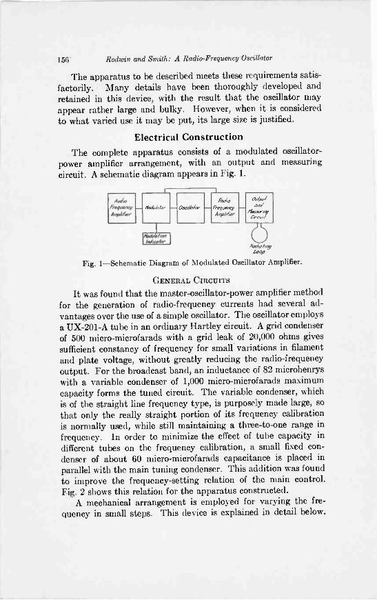
156' Radian and Smith: A Radio -Frequency Oscillator
The apparatus to be described meets these requirements satis-factorily. Many details have been thoroughly developed andretained in this device, with the result that the oscillator mayappear rather large and bulky. However, when it is consideredto what varied use it may be put, its large size is justified.
Electrical ConstructionThe complete apparatus consists of a modulated oscillator -
power amplifier arrangement, with an output and measuringcircuit. A schematic diagram appears in Fig. 1.
Audio&pigmyAmplifier
lloaldplor ascdbfa..-Ra0%0
- frequencyrphlier
ad,/und
/lep.s.essi0.11,01.
RshotimeLego
Fig. 1-Schematic Diagram of Modulated Oscillator Amplifier.
GENERAL CIRCUITS
It was found that the master -oscillator -power amplifier methodfor the generation of radio -frequency currents had several ad-vantages over the use of a simple oscillator. The oscillator employsa UX-201-A tube in an ordinary Hartley circuit. A grid condenserof 500 micro-microfarads with a grid leak of 20,000 ohms givessufficient constancy of frequency for small variations in filamentand plate voltage, without greatly reducing the radio -frequencyoutput. For the broadcast band, an inductance of 82 microhenryswith a variable condenser of 1,000 micro-microfarads maximumcapacity forms the tuned circuit. The variable condenser, whichis of the straight line frequency type, is purposely made large, sothat only the really straight portion of its frequency calibrationis normally used, while still maintaining a three -to -one range infrequency. In order to minimize the effect of tube capacity indifferent tubes on the frequency calibration, a small fixed con-denser of about 60 micro-microfarads capacitance is placed inparallel with the main tuning condenser. This addition was foundto improve the frequency -setting relation of the main control.Fig. 2 shows this relation for the apparatus constructed.
A mechanical arrangement is employed for varying the fre-quency in small steps. This device is explained in detail below.
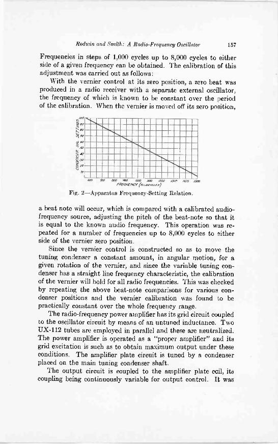
Rodwin and Smith: A Radio -Frequency Oscillator 157
Frequencies in steps of 1,000 cycles up to 8,000 cycles to eitherside of a given frequency can be obtained. The calibration of thisadjustment was carried out as follows:
With the vernier control at its zero position, a zero beat wasproduced in a radio receiver with a separate external oscillator,the frequency of which is known to be constant over the periodof the calibration. When the vernier is moved off its zero position,
010
eo
Nye
)20,0
WV WO $10 WV IWO IMO WOO
PRE-OW/WY (iticocrext0)
Fig. 2-Apparatus Frequency -Setting Relation.
IWO MOO ,Cf00
a beat note will occur, which is compared with a calibrated audio-frequency source, adjusting the pitch of the beat -note so that itis equal to the known audio frequency. This operation was re-peated for a number of frequencies up to 8,000 cycles to eitherside of the vernier zero position.
Since the vernier control is constructed so as to move thetuning condenser a constant amount, in angular motion, for agiven rotation of the vernier, and since the variable tuning con-denser has a straight line frequency characteristic, the calibrationof the vernier will hold for all radio frequencies. This was checkedby repeating the above beat -note comparisons for various con-denser positions and the vernier calibration was found to bepractically constant over the whole frequency range.
The radio -frequency power amplifier has its grid circuit coupledto the oscillator circuit by means of an untuned inductance. TwoUX-112 tubes are employed in parallel and these are neutralized.The power amplifier is operated as a "proper amplifier" and itsgrid excitation is such as to obtain maximum output under theseconditions. The amplifier plate circuit is tuned by a condenserplaced on the main tuning condenser shaft.
The output circuit is coupled to the amplifier plate coil, itscoupling being continuously variable for output control. It was
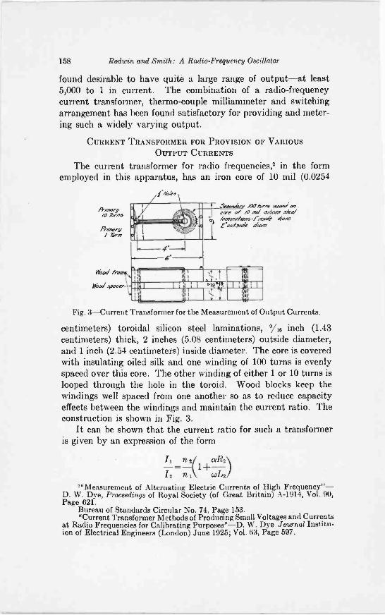
158 Rodwin and Smith: A Radio -Frequency Oscillator
found desirable to have quite a large range of output-at least5,000 to 1 in current. The combination of a radio -frequencycurrent transformer, thermo-couple milliammeter and switchingarrangement has been found satisfactory for providing and meter-ing such a widely varying output.
CURRENT TRANSFORMER FOR PROVISION OF VARIOUS
OUTPUT CURRENTS
The current transformer for radio frequencies,2 in the formemployed in this apparatus, has an iron core of 10 mil (0.0254
1.4611,
liwnoryo Turns
Pr/mo,s,/ Turn
Wood Myna
Ykolioocer
Seoo,o6ey ,420 torok, woo," oocere of /0 ox/ o400n sfrofloolootans-Po dewloo/..51641 maul.
Fig. 3-Current Transformer for the Measurement of Output Currents.
centimeters) toroidal silicon steel laminations, 9/16 inch (1.43centimeters) thick, 2 inches (5.08 centimeters) outside diameter,and 1 inch (2.54 centimeters) inside diameter. The core is coveredwith insulating oiled silk and one winding of 100 turns is evenlyspaced over this core. The other winding of either 1 or 10 turns islooped through the hole in the toroid. Wood blocks keep thewindings well spaced from one another so as to reduce capacityeffects between the windings and maintain the current ratio. Theconstruction is shown in Fig. 3.
It can be shown that the current ratio for such a transformeris given by an expression of the form
1+aR2\/2 n1 co/A2)
'"Measurement of Alternating Electric Currents of High Frequency"-D. W. Dye, Proceedings of Royal Society (of Great Britain) A-1914, Vol. 90,Page 621.
Bureau of Standards Circular No. 74, Page 153."Current Transformer Methods of Producing Small Voltages and Currents
at Radio Frequencies for Calibrating Purposes"-D. W. Dye Journal Institu-ion of Electrical Engineers (London) June 1925; Vol. 63, Page 597.
111.1..1
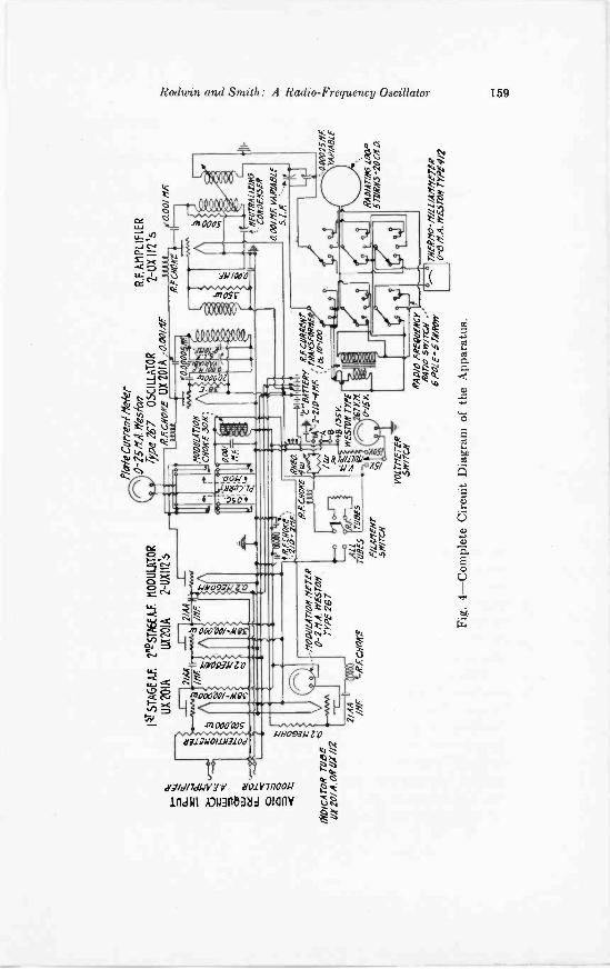
IND
ICA
TO
R T
UB
EtS
UK
20/
A O
R D
X //
2
I47S
TA
GE
A,
21eS
TM
EA
1 M
OD
ULA
TO
R
UX
201
AU
X20
1A2-
UX
II2's
-NO
DU
LA
T/O
R f
ir T
ER
0-2
NA
. WE
STO
NT
YR
E 2
67
2/A
A /Of
RF.
CH
O/a
I -
flin
ie C
urre
n?' M
etie
r0-
15 &
A. f
rres
ivll
Typ
e 76
'7O
SC
ILLA
TO
RR
f:C
110/
fE L
IX20
1A ,,
aoom
fR
E C
1/0/
2113
...I[zr
a00/
0 00
MO
DU
LA
TIO
NC
HO
KE
30R
;
100
0/1
Nf.
WO
O 1
44
RA
CN
OM
,2/0
-R
HE
AR
deci
ore
41.
#sca
Rzw
ru.
44e
-2-2
/0-4
/1F:
11:
749/
15z,
1A a
TU
BA
Sra
81:5
.;9/
05Y
.A
LL
47 y
.m.
WE
STV
N r
yes
6.0
-/SK
O
f/L
AR
EN
TSW
ITC
H
VO
LT
ME
TE
RSW
ITC
HR
AD
IO f
ReQ
VIR
CT
R47
/0 S
wir
CH
.6
RO
IE-S
TR
RO
PY
Fig.
4-C
ompl
ete
Cir
cuit
Dia
gram
of
the
App
arat
us.
R.F
.AM
PLI
FIE
R2
-OX
112
's
L_
CO
ND
EN
SER
0.00
//fl.
VA
R/A
BL
E5.
1.R
'400
025N
A:
YA
R/A
BL
E
RA
O/A
7/06
thO
P57
7/0/
5-20
C R
D
riaf
iro-
/f/a
/AM
YE
TE
R01
6 R
:A. W
EST
ON
TY
RE
*?
CO
CO
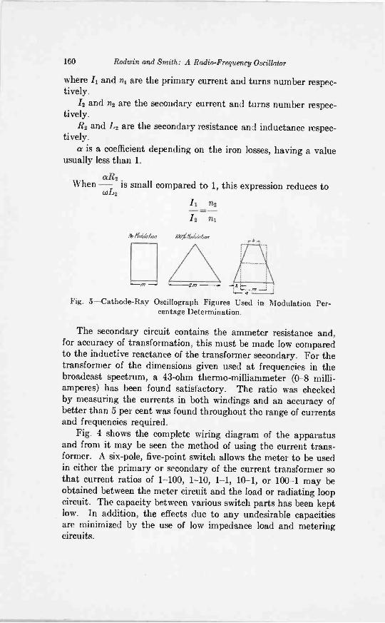
160 Rodwin and Smith: A Radio -Frequency Oscillator
where Ii and n1 are the primary current and turns number respec-tively.
/2 and n2 are the secondary current and turns number respec-tively.
R2 and L2 are the secondary resistance and inductance respec-tively.
a is a coefficient depending on the iron losses, having a valueusually less than 1.
When -CER2 is small compared to 1, this expression reduces to01/.2
lb itktfflrh --
-,x ,-: ,...-m -.: ;...- ,,,
Fig. 5-Cathode-Ray Oscillograph Figures Used in Modulation Per-centage Determination.
1
The secondary circuit contains the ammeter resistance and,for accuracy of transformation, this must be made low comparedto the inductive reactance of the transformer secondary. For thetransformer of the dimensions given used at frequencies in thebroadcast spectrum, a 43 -ohm thermo-milliammeter (0-8 milli-amperes) has been found satisfactory. The ratio was checkedby measuring the currents in both windings and an accuracy ofbetter than 5 per cent was found throughout the range of currentsand frequencies required.
Fig. 4 shows the complete wiring diagram of the apparatusand from it may be seen the method of using the current trans-former. A six -pole, five -point switch allows the meter to be usedin either the primary or secondary of the current transformer sothat current ratios of 1-100, 1-10, 1-1, 10-1, or 100-1 may beobtained between the meter circuit and the load or radiating loopcircuit. The capacity between various switch parts has been keptlow. In addition, the effects due to any undesirable capacitiesare minimized by the use of low impedance load and meteringcircuits.
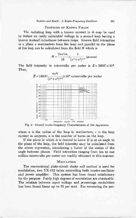
Roduin and Smith: A Radio -Frequency Oscillator 161
PROVISION OF KNOWN FIELDS
The radiating loop with a known current in it may be usedto induce an easily calculated voltage in a second loop having aknown mutual inductance between loops. Known field intensitiesin a plane x centimeters from the loop and parallel to the planeof the loop can be calculated from the field H which is
2iratin 1H= (
10X(x2d-a2)3/
2gausses)
The field intensity in microvolts per meter is E= 300H x 108.Thus,
naziE= 18850
(x2-1-a2) 3/2X106 microvolts per meter
IIIIMMME111111111111=1111111111IIIIIMMIMEM1111111111111ftlitill111111111111111111111111111=11MMIMIIII
1111111111111MM11111111111111111111111111111IIIIIIMME111111111111111111111111111111111111=IIIMMIIIIIIMIN1111111111111111111111111111M1111111111111111111111111111111111111111111111111111111111111MIMMIIIIIIIIM11111111111111
meeFREQUENCY CYCLE3 PER 1ECONV
Fig. 6-Overall Audio -frequency Characteristics of the Apparatus.
where a is the radius of the loop in centimeters, i is the loopcurrent in amperes, n is the number of turns on the loop.
If the plane in which it is desired to know E is at an angle tothe plane of the loop, the field intensity may be calculated fromthe above expression, introducing a factor of the cosine of theangle between planes. Field intensities ranging from ten to onemillion microvolts per meter are readily obtained in this manner.
MODULATION
The conventional plate -circuit choke coil method is used formodulation, two UX-112 tubes controlling both master -oscillatorand power amplifier. This system has been found satisfactoryfor the purpose. Fairly high degrees of modulation are obtainable.The relation between input voltage and percentage modulationhas been found linear up to 70 per cent. For measuring the per-
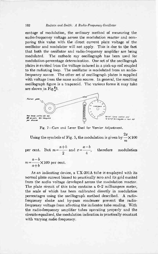
162 Rodwin and Smith: A Radio -Frequency Oscillator
centage of modulation, the ordinary method of measuring theaudio -frequency voltage across the modulation reactor and com-paring this value with the direct current plate voltage of theoscillator and modulator will not apply. This is due to the factthat both the oscillator and radio -frequency amplifier are beingmodulated. The cathode ray oscillograph has been used formodulation -percentage determination. One. set of the oscillographplates is excited from the voltage induced in a pick-up coil coupledto the radiating loop. The oscillator is modulated from an audio -frequency source. The other set of oscillograph plates is suppliedwith voltage from the same audio source. In general, the resultingoscillograph figure is a trapezoid. The various forms it may takeare shown in
P*10 eebeno/ d//aim.s.o.s fel kbeyebe
par*raver limy co,/n/ dv/
+$.16 Adorri. 4/
Fig. 7-Cam and Lever Used for Vernier Adjustment.
2xUsing the symbols of Fig. 5, the modulation is given by -X100
m
a + b a- bper cent. But m = - and x =
2 4therefore modulation
a -bm = X 100 per cent.
As an indicating device, a UX-201A tube is employed with itsnormal plate current biased to practically zero and its grid excitedfrom the audio voltage developed across the modulation reactor.The plate circuit of this tube contains a 0-2 milliampere meter,the scale of which has been calibrated directly in modulationpercentages using the oscillograph method described. A radio -frequency choke and by-pass condenser prevent the radio -frequency voltage from affecting the indicator tube reading. Withthe radio -frequency amplifier tubes operating properly and thecircuits equalized, the modulation indication is practically constantwith varying radio frequency.
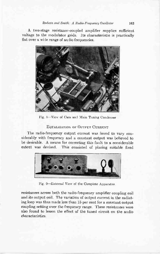
Rodwin and Smith: A Radio -Frequency Oscillator 163
A two -stage resistance -coupled amplifier supplies sufficientvoltage to the modulator grids. Its characteristic is practicallyflat over a wide range of audio frequencies.
Fig. 8-View of Cam and Main Tuning Condenser
EQUALIZATION OF OUTPUT CURRENT
The radio -frequency output current was found to vary con-siderably with frequency and a constant output was believed tobe desirable. A means for correcting this fault to a considerableextent was devised. This consisted of placing suitable fixed
Fig. 9-External View of the Complete Apparatus.
resistances across both the radio -frequency amplifier coupling coiland its output coil. The variation of output current in the radiat-ing loop was thus made less than 15 per cent for a constant outputcoupling setting over the frequency range. These resistances werealso found to lessen the effect of the tuned circuit on the audiocharacteristics.
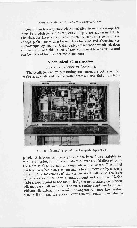
164 Rodwin and Smith: A Radio -Frequency Oscillator
Overall audio -frequency characteristics from audio -amplifierinput to modulated radio -frequency output are shown in Fig. 6.
The data for these curves were taken by rectifying some of thevoltage picked up with a biased detector tube and observing theaudio -frequency output. A slight effect of resonant circuit selection
still remains, but this is not of any considerable magnitude andcan be allowed for in exact measurements.
Mechanical ConstructionTUNING AND VERNIER CONTROLS
The oscillator and output tuning condensers are both mounted
on the same shaft and are controlled from a single dial on the front
Fig. 10-Internal View of the Complete Apparatus.
panel. A friction cam arrangement has been found suitable forvernier adjustment. This consists of a lever and friction plate onthe main shaft and a cam on a separate vernier shaft. The end ofthe lever arm bears on the cam and is held in position by a strongspring. Any movement of the vernier shaft will cause the leverto move either up or down a small amount and, since the frictionplate is now bound to the main shaft, the main tuning condenserswill move a small amount. The main tuning shaft can be movedwithout disturbing the vernier arrangement, since the frictionplate will slip and the vernier lever arm will remain fixed due to
Rodwin and Smith: A Radio -Frequency Oscillator 165
the combined action of the spring and the cam rest. The criterionof whether such a system will operate is that the force required tomove the friction plate over its bearing should be greater than thebearing friction in the tuning condensers. In practice, this is easilyaccomplished. The details may be seen in Figs. 7 and 8.
The whole apparatus is mounted in a double copper shieldedbox. The front panel and base board have been made removableas a unit for convenience. The various units, such as audio -frequency amplifier, oscillator, radio -frequency amplifier, andoutput circuit, are shielded from one another. The details maybe seen in Figs. 9 and 10. The grid batteries are located in aseparate compartment, but the filament battery of six volts andthe plate battery of 135 volts are located outside the shielded box.Radio -frequency filters in the battery leads prevent radiationfrom these.
The thermo-milliammeter for the measurement of output isplaced externally near the apparatus, a twisted pair of leads ofshort length being used for connections.
In conclusion, we desire to mention that this design was carriedout under the direction of Mr. Julius Weinberger, whose sug-gestions were very valuable in the development of the equipment.
ON THE INFLUENCE OF SOLAR ACTIVITY ONRADIO TRANSMISSION*
BY
L. W. AUSTIN AND MISS I. J. WYMORE(Laboratory for Special Radio Transmission Research, Bureau of Standards)
Summary-The paper describes further examination of the daylight longwave signal measurements of the Bureau of Standards for evidence of correlationwith solar activity. It has already been shown that a probable correlation existsbetween signals and sunspots when the observations are continued for several yearsand are averaged in periods of a month or more. The present paper deals especiallywith observations averaged in shorter (5 -day) periods. Here while the relationshipis generally evident it is sometimes obscured by an apparent relative phase shiftbetween the signal and sunspot curves.
ATthe meeting of the American Section of the U.R.S.I. inApril, 1927, some curves were shown' indicating a relation-ship between very long wave transatlantic radio reception
and solar activity as measured by sunspot numbers and by thevalues of the solar constant. These curves represented annualaverages from 1915 to 1926, and monthly averages from 1922 to1926. These indicated without much question that there existsa direct correlation between solar activity and daylight signals,when averaged over long periods. Curves were also shown illustrat-ing the correspondence of 27 -day periodic averages of sunspotsand reception.
G. W. Pickard' had previously published a paper using hisown observations in the broadcasting band, as well as the ob-servations of others, on very long as well as ultra short wave-lengths, in which he produced striking evidence of the dependenceof radio phenomena on solar activity. Mr. Pickard's own observa-tions indicated quite positively an inverse relationship betweenthe strength of night signals in the broadcasting band and sunspotnumbers, while the ultra short wave night signal material treatedby the same methods, indicated a direct correlation. This lastconclusion is, however, seemingly not in agreement with a number
* Publication approved by the Director of the Bureau of Standards of theU. S. Department of Commerce.
Original Manuscript Received by the Institute, December 20, 1927.Read at the International meeting of the Union of Scientific Radio
Telegraphy in Washington, October 14, 1927.1 PROC. I. R. E. Vol. 15, p. 825, 1927.2 PROC. I. R. E. Vol. 15, p. 83, 1927. See also Vol. 15, p. 749, 1927.
166
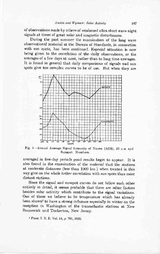
Austin and Wymore: Solar Activity 167
of observations made by others of weakened ultra short wave nightsignals at times of great solar and magnetic disturbances.
During the past summer the examination of the long waveobservational material at the Bureau of Standards, in connectionwith sun spots, has been continued. Especial attention is nowbeing given to the correlation of the daily observations, or theaverages of a few days at most, rather than to long time averages.It is found in general that daily comparisons of signals and sunspots give too complex curves to be of use. But when they are
40
30
20
00
io
40
SO
0
OFEW
S../,.S/b7,
ANS 76 /7 2I / '77 '.154,YEARS
se"
Fig. 1-Annual Average Signal Intensity of Nauen (AGS), 10 A.M. andSunspot Numbers.
averaged in five-day periods good results begin to appear. It isalso found in the examination of the material that the stationsat moderate distances (less than 1000 km.) when treated in thisway give on the whole better correlation with sun spots than moredistant stations.
Since the signal and sunspot curves do not follow each otherentirely in detail, it seems probable that there are other factorsbesides solar activity which contribute to the signal variations.One of these we believe to be temperature which has alreadybeen shown' to have a strong influence especially in winter on thereception in Washington of the transatlantic stations at NewBrunswick and Tuckerton, New Jersey.
3 Paoc. I. R. E. Vol. 14, p. 781, 1926.
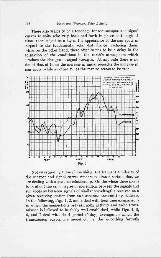
168 Austin and Wymore: Solar Activity
There also seems to be a tendency for the sunspot and signalcurves to shift relatively back and forth in phase as though attimes there might be a lag in the appearance of the sun spots inrespect to the fundamental solar disturbance producing them,while on the other hand, there often seems to be a delay in theformation of the conditions in the earth's atmosphere whichproduce the changes in signal strength. At any rate there is nodoubt that at times the increase in signal precedes the increase insun spots, while at other times the reverse seems to be true.
20
/0
0
NoNTPLY arw.inON PROMJ YEAR MONTHLY AVERAGESOP SUNSPOT NUMBERS ANDSIGNAL r, per Aosov,or)
/0 Mr & JPA,
Jf
1.
I
I
ti
A
.011AWP011,
if or 4 Af ./99.4
Ntsar
Fig. 2
2 1"Mt.
40
30
20
Notwithstanding these phase shifts, the frequent similarity ofthe sunspot and signal curves renders it almost certain that weare dealing with a genuine relationship. On the whole there seemsto be about the same degree of correlation between the signals andsun spots as between signals of similar wavelengths received at agiven receiving station from two separate transmitting stations.In the following, Figs. 1, 2, and 3 deal with long time comparisonsin which the connections between solar activity and radio trans-mission is believed to be fairly well established, while Figs. 4, 5,6, and 7 deal with short period (5 -day) averages in which thetransmission curves are smoothed by the smoothing formula
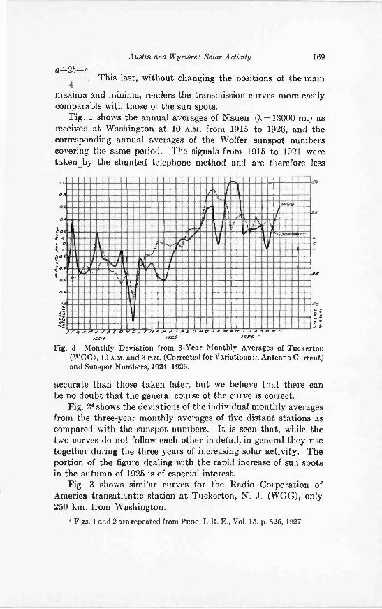
Austin and Wymore: Solar Activity 169
a+2b+c. This last, without changing the positions of the main
4maxima and minima, renders the transmission curves more easilycomparable with those of the sun spots.
Fig. 1 shows the annual averages of Nauen (X=13000 m.) asreceived at Washington at 10 A.M. from 1915 to 1926, and thecorresponding annual averages of the Wolfer sunspot numberscovering the same period. The signals from 1915 to 1921 weretakenby the shunted telephone method and are therefore less
4t0
0
t as
ai
MMEMMEMMEMMEMEMEMMEMMEMMEMONMEMEMMUMMEM,MEMEMMMMOIMMEMMEMMINIMMEMOMMUMMEMMEMOMMEMMMEMMEMMEMMEMMEMEMMOMMEMMOWAMMEMMOMMEMEMMMMEMMEMMEMMEMMEMMEMEMEMPIIMMOMMEMMEMEMAMMEMMMEMEMEMMEMMEMMUMMIPOMMEHMEMMOMEMMEMmmommommmommommummorammnimmmummummumMMEMMEMMEMEMMEMMOMMIIMENMOMMEWSWOOMUMEMEMIMMEMMIIMMEMEMMEMMEMEMMAMOCIFUMUMOOWAMMEMIIummommommommummomnmonummireAstmommmimmmummommommommmmammnimmammimatizzanI11MMO11MINIMMEMEWPINn4AMMIOWIMMIMMERIMMEMMECIIMMUMMEMMMEMEMMINCIIMMEMMEMEMEMMANIMMEMMflummanwummammuommumminummmommomIIIIMMUMOUHMEMAMMEMAMMMEMMEMEMMEMEMMEMMINIMAWMINAMWAHMUOMMEWMINIMMEMMEMMEMMEMEMMEWMEmoninmammswicsamnimmommommommommommRMINIMMEMBRIMPOMSNUMMEMEMIIMMEMMEMMEMMEMMEMMEMMEMMEMMUMEMMINIMEMMEMOMMMEMMEMMUMMEMMMINIEMEMMINIMINIMMEMEMMEMEMEMMEMMEMEMMEMINIMIMMINIMMIIMERWIMMEMMEMMEMMEMEMEMMEMMEMMEMMMMEMMEMOIMMIIMMEMMEMMINIMMEMEMMEMMEMMEMMEMEMEMMEMMEMOMOMMEMOMMMEMMUMMEMMEMMOMMOMMEMMEMIIMMOMMEMMOOMMEMMEMMEMMEMMOMMOMMEMIIMMOMMEMMEMMMEMEMMEMMEMMEMMEMMEMMEMMEMMEMMEMMEMMEMMEMMEMMEMMEMMEMMOMMENNOMMEMMEMM
JFIYA MaaASON0aRMAMO ASON0d/MAMWaAJOND/924 4225" /926
Fig. 3-Monthly Deviation from 3 -Year Monthly Averages of Tuckerton(WGG), 10 A.M. and 3 P.M. (Corrected for Variations in Antenna Current)and Sunspot Numbers, 1924-1926.
accurate than those taken later, but we believe that there canbe no doubt that the general course of the curve is correct.
Fig. 24 shows the deviations of the individual monthly averagesfrom the three-year monthly averages of five distant stations ascompared with the sunspot numbers. It is seen that, while thetwo curves do not follow each other in detail, in general they risetogether during the three years of increasing solar activity. Theportion of the figure dealing with the rapid increase of sun spotsin the autumn of 1925 is of especial interest.
Fig. 3 shows similar curves for the Radio Corporation ofAmerica transatlantic station at Tuckerton, N. J. (WGG), only250 km. from Washington.
4 Figs. 1 and 2 are repeated from PROC. I. R. E., Vol. 15, p. 825, 1927.
ZS
Jo
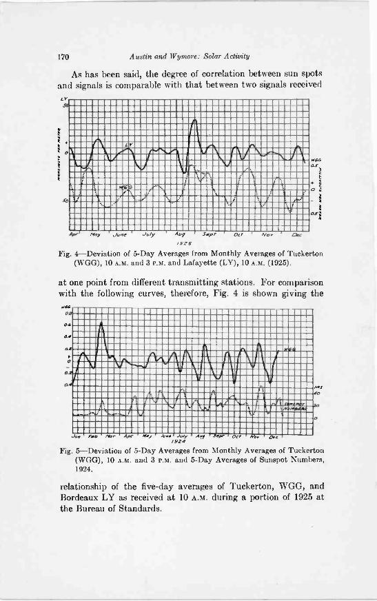
170 Austin and Wymore: Solar Activity
As has been said, the degree of correlation between sun spotsand signals is comparable with that between two signals receivedLv
So
L r
tyr
we -is
1.1
AP'. Ploy June r July Aof Sep, Oct It/o., r Dec
1925
Fig. 4-Deviation of 5 -Day Averages from Monthly Averages of Tuckerton(WGG), 10 A.M. and 3 P.M. and Lafayette (LY), 10 A.m. (1925).
Wasas
1
o 4
a.$1
r
at one point from different transmitting stations. For comparisonwith the following curves, therefore, Fig. 4 is shown giving the
.781
a
OP4
a
4"'
.11A
**\/
A f
a
Ml
20
0
.44 5.9 Nor Apr Noy Juin July Av dW 003' Woo. Poe/924
Fig. 5-Deviation of 5 -Day Averages from Monthly Averages of Tuckerton(WGG), 10 A.m. and 3 P . M . and 5 -Day Averages of Sunspot Numbers,1924.
relationship of the five-day averages of Tuckerton, WGG, andBordeaux LY as received at 10 A.M. during a portion of 1925 atthe Bureau of Standards.
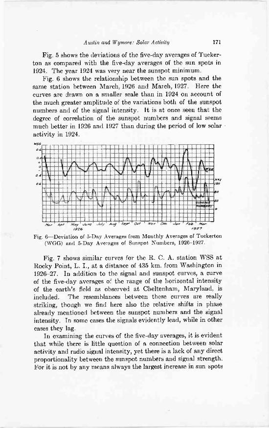
Austin and Wymore: Solar Activity 171
Fig. 5 shows the deviations of the five-day averages of Tucker -ton as compared with the five-day averages of the sun spots in1924. The year 1924 was very near the sunspot minimum.
Fig. 6 shows the relationship between the sun spots and thesame station between March, 1926 and March, 1927. Here thecurves are drawn on a smaller scale than in 1924 on account ofthe much greater amplitude of the variations both of the sunspotnumbers and of the signal intensity. It is at once seen that thedegree of correlation of the sunspot numbers and signal seemsmuch better in 1926 and 1927 than during the period of low solaractivity in 1924.
04
0.4
O
0.4
0.4
..IMIIM
k
a1W11111
A
11.111111111MV
rV
fi
LIVeltlif
go
Alt, AP' 14 ay 5 Oa Nor Lilaw JON Abh Nor./424 /927
Fig. 6-Deviation of 5 -Day Averages from Monthly Averages of Tuckerton(WGG) and 5 -Day Averages of Sunspot Numbers, 1926-1927.
Fig. 7 shows similar curves for the R. C. A. station WSS atRocky Point, L. I., at a distance of 435 km. from Washington in1926-27. In addition to the signal and sunspot curves, a curveof the five-day averages of the range of the horizontal intensityof the earth's field as observed at Cheltenham, Maryland, isincluded. The resemblances between these curves are reallystriking, though we find here also the relative shifts in phasealready mentioned between the sunspot numbers and the signalintensity. In some cases the signals evidently lead, while in othercases they lag.
In examining the curves of the five-day averages, it is evidentthat while there is little question of a connection between solaractivity and radio signal intensity, yet there is a lack of any directproportionality between the sunspot numbers and signal strength.For it is not by any means always the largest increase in sun spots
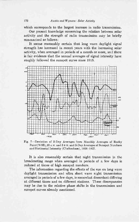
172 Austin and Wymore: Solar Activity
which corresponds to the largest increase in radio transmission.Our present knowledge concerning the relation between solar
activity and the strength of radio transmission may be brieflysummarized as follows:
It seems reasonably certain that long wave daylight signalstrength has increased in recent years with the increasing solaractivity, when averaged in periods of a month or more, and thereis fair evidence that the annual averages of signal intensity haveroughly followed the sunspot curve since 1915.
,mmummummommmommommommummommumm momminommommommommimmommommummommommm.mmommemmummmummummommommommommommmommommemmommnimmummommummimmommomimmummommonaummommommommommommomMMEMMEMMOMMMIAMAMMEMMEMMUMMEMMOMMEMMEMEMmmummummommorummommrammummommomm.-mummommommimmmaamminimmulgummommummommomwmommimmimmommummmmommorsomulamemmmummommammmummommmumminsmmisammammgmlimmommaymummummommommmamrsmaammazaummommummumummilmommtmmormummummommmmommummammommommimmircammamummommommMEMMEMIUMMWMMEMMIIMMAMMMUMMEMIIIMPAMEMMEMMMMOMMINWEMAMMINIMMEMMEMMEMMOVAMMENIMMEMumminamminmemmommummumommasmummomMMOMMEIREMMEMMMERWAWMARIMERMEMEMIEROWMEMOMMINIMUMOMMWENOUMWUMEMMEMEONOOMMEMMUWMEHMENVINPAMMENWIREMEMMEMMEMMOW2QMHMEMMOMMNOMMILIFRIIMMERMEMOMMEMEMOMMEMMEMWHIMMEMMliWOMMWEMEMMigalIMMEMMEMMEMMMEMEMMIMMEMMEMMMMIMOMMMJIMMEMMEMMEMMEMMEMEMEMEMMEMMAIMMEINAMMIIIMUMMEMMOMMEMMUNMEMMINIMEMMIIMMAEMEMMWEEMOMMILMEMEMMEMMIVIEWMEMEMOMMKIIMZUMMAMMOMMEMMEMMOMMMIUMUMMICIPMNIPMIKAIMMIIMMIIMMMICOMMEMEMMZEMEMMAIMMEMEMMEMONMEMMEWOMMEMEMEMOIMMEMEMEMOIMMEMMOMEMMEMMUINUAMMOMMEMMEMOMMEMMEMOMEMEMEMMEMMEMMIIMMEMEMOMMIUMMOMMEMMEMEMMEMMINIMMEMEMMEMMEMMEMOMMEOMMMEMEMOMMEMMEMEMMUMMEMMEMEMEMOMEMEMM
4wr Oct Her D.0 Jam
10
,6 Mat -4927
Aar
HV
r
00
Fig. 7-Deviation of 5 -Day Averages from Monthly Averages of RockyPoint (WSS), 10 A.M. and 3 P.M. and 5 -Day Averages of Sunspot Numbersand Horizontal Intensity (Cheltenham), 1926-1927.
It is also reasonably certain that night transmission in thebroadcasting range when averaged in periods of a few days isreduced at times of high sunspot numbers.
The information regarding the effects of the sun on long wavedaylight transmission and ultra short wave night transmissionaveraged in periods of a few days, is somewhat discordant differingat different times and on different stations. These discrepanciesmay be due to the relative phase shifts in the transmission andsunspot curves already mentioned.
Austin and Wymore: Solar Activity 173
Very few observations have been published on long wavenight transmission, on broadcasting day transmission, nor, sofar as is known, have any been made on broadcasting night trans-mission extending over more than one year.
There is in general a rough resemblance observed in the receptioncurves of different long wave stations lying in different directionsfrom Washington. This would seem to imply either that thereare simultaneous changes in the electrical conditions in the upperatmosphere over very large areas or that the conditions in theimmediate neighborhood of the receiving station form the chiefcontrolling factor in signal strength. Occasionally, however,marked differences in reception from stations in different directionshave been noted, a phenomenon which is much more commonin the case of the broadcasting and ultra short waves at night.
While the sunspot numbers give a rough indication of theconditions governing transmission, it seems probable that theyare only an imperfect index of the particular form of solar activitywhich apparently is the chief agent in controlling radio phe-nomena.
IONIZATION IN THE UPPER ATMOSPHERE*
BY
E. 0. HIILBURT(Naval Research Laboratory, Bellevue, Washington, D. C.)
THE more important agencies which may conceivably causethe ionization of the upper atmosphere of the earth are theultra -violet light, a and 13 particles, all of solar origin, the
penetrating radiation of cosmic origin, and the ionizing radiationsfrom terrestrial sources. The last mentioned may perhaps beruled out immediately because of the fact that the conductivityof the lower atmospheric strata increases rapidly with the heightfor the first few kilometers. The possible effects of these ionizingagencies have been considered in papers by Chapman and Milne,Benndorf, Elias, Lassen and others. Recently experiments withthe electromagnetic waves of radio telegraphy together withtheories of the propagation of these waves over the surface of theearth have led to information about the ionization in the upperatmosphere more definite than hitherto obtainable, and it has beenof interest to examine again the causes of the ionization.
The experiments of Breit and Tuve with 70 -meter waves, ofAppleton with 400 -meter waves, of Heising with 57- and 111 -meterwaves, of Wagner and Quack with 15- and 16 -meter waves, ofHollingsworth and Eckersley with long waves, and the experimentsof Taylor on the skip distances of waves below 50 meters and thetheoretical considerations of Taylor and Hulburt on these skipdistances, show that the electron density N increases with theheight Z above the earth reaching a value of about 4 X 10⁶; abovethe height where N has this value the electron density is not knownexcept that it does not go on increasing. Although the radiodata are none too extensive, it may be taken that in the day time(for the North Temperate Zone) the height where N is of the order106 is roughly 150 to 200 km.
Because of the diurnal variation in the ionization, we choosethe ultra -violet light of the sun as being the ionizing agency de-serving first consideration. In order to make an explicit calculation
Original Manuscript Received by the Institute December 6 1927. Abstract of a paper read at the open meeting of the U. R. S. I. at
Washington, D. C., October 1927. Communication from the American Section of the International Union
for Scientific Radiotelegraphy.
174
Hulburt: Ionization in Upper Atmosphere 175
of the ionization the temperature, the pressure, and the constituentgases and their partial pressures must be known at each heightin the upper atmosphere. These we may take as given completelyin the classical thermodynamic isothermal equilibrium theory ofHumphreys, Jeans, and others. There is a question as to theexistence of hydrogen in the upper atmosphere, but the conclusionsgiven later are much the same whether hydrogen is there or not.There is also the question of ozone, or oxygen, which may be ofgreat importance. The law of the recombination of the electronswith the positive ions must be known. For this we have J. J.Thomson's theory of recombination, and complete formulas areavailable; We must also recognize the possibility of the electronattaching itself to a neutral molecule, for when it does this, therebyproducing a negative ion, it is no longer an energetic refractor ofthe radio waves. The oxygen molecule is the only important onein this connection, and the values of the attachment coefficientmeasured in the laboratory for pressures of 10 mm. of mercuryand above must be extrapolated to pressures below 10-2 mm.,perhaps a questionable extrapolation. The diffusion of the elec-trons and ions must be considered; this is a very important in-fluence. Using all these things and making entirely acceptableassumptions as to the amount of ultra -violet light from the sunin the spectral region useful for ionization the N,Z curve risesfrom N= 0 at 50 km. to the order of 105 at Z-140 km. in thewinter time; above this height N falls off rapidly. In the summertime the electron bank is higher and denser than in the winter.The N,Z curve is in fair accord with the radio data for full daylightconditions, and its change at night is, as far as can be seen, inagreement with night time radio conditions. Below the electronbank there is an ion bank. The exact density of the ions is uncer-tain, but it seems possible that these may persist in sufficientquantities to play a part in the refraction of the longer radio waves.The uncertainty is due to the lack of exact knowledge of the forma-tion and recombination of the positive and negative ions; thequestion seems to be inextricably bound up with and confused bythe presence of ozone, the laws of ozone formation and destructionbeing quite unknown.
On the whole it seems that the ultra -violet light of the sun isa necessary and sufficient cause of the Kennelly -Heaviside layer.This means that it is not necessary to consider possible effectsof other agencies of ionization, such as a and /3 particles etc.,
176 Hulburt: Ionization in Upper Atmosphere
except as secondary, or unusual effects, which may of course bequite important, as the recent correlations between sun spotsand radio transmission indicate. In conclusion we must emphasizethe view that we can see no possibility of the existence of electronbanks above the main one which has its maximum electronicdensity at a height around 150 to 200 km. and therefore thatinferences from radio data which suggest the presence of suchoutlying layers must be examined with care before they can beaccepted.
A THEORY OF THE UPPER ATMOSPHERE ANDMETEORS*
BY
H. B. MARIS(Naval Research Laboratory, Bellevue, Washington, D. C.)
Summary-A calculation of the rate of separation of gases of different densityin the eanth's atmosphere leads us to expect a uniform mixture of all gases below100 km and densities of hydrogen and helium roughly a hundred thousandthof those previously calculated, for greater heights. Known absorption and radia-tion coefficients for gases of the upper atmosphere indicate that we should expect adaily temperature variation of about 140° during the summer and 30° during thewinter for all heights greater than 80 km. Carbon dioxide is found to be moreeffective than water vapor in determining the final escape of radiation from theearth and the conclusion is drawn that variations in the carbon dioxide contentof the air may explain the variation in climatic conditions of the earth indicatedby the ice ages of the past. Frictional resistance offered by the upper atmosphereto the passage of meteors through it is not sufficient to account for the energyradiated by meteors and the conclusion is reached that the energy of the meteor isprobably dissipated into the air by the escape of atoms and molecules driven fromthe meteor by the energies of impacts with molecules of the air.
THE force of gravity acting on the atmosphere of the earthcauses the heavier gases to settle downward and the lightergases to rise to higher altitudes by diffusion but winds un-
hindered by diffusion would by convection keep the compositionof the air uniform at all elevations. The classical ideas of thechange in atmospheric pressure with altitude (e.g., Humphrey,Jeans, Chapman and Milne, etc.) have been based on the assump-tion that convection is negligible, at least in the upper atmosphere,and that each gas is, through diffusion, in gravity equilibriumwith its own partial pressure. Investigation has shown, however,that diffusion is of importance only at elevations greater than100 km.
The ordinary equations of diffusion show at once that if theair were uniformly mixed at all altitudes and then left free fromall convection currents, there would be a constant flow of lightermolecules upward and of heavier molecules downward, whichwould be independent of the altitude until a level was reached
Communication from the American Section of the International Unionfor Scientific Radiotelegraphy.
Manuscript Received by the Institute, December 6, 1927.* Abstract of a paper read at the meeting of the U. R. S. I., at Washing-
ton, D. C., October 13, 1927.
177
178 Math: Upper Atmosphere and Meteors
where the diffusing gas would be in gravity equilibrium. Thisdiffusion level for hydrogen would move from infinity down to142 km. in one day, at the end of five days it would be at a heightof 127 km. and in 50 days it would be at 113 km. The correspond-ing levels for helium would be at 137, 120 and 106 km., respectively.The new calculations give hydrogen and helium densities above150 km. roughly 1/100,000 of the values previously calculated.
Recent use of the upper atmosphere as a medium for trans-mitting electromagnetic radiation of wavelength 10 to 10,000meters has emphasized the importance of knowledge, or at leastof a theory, of changes which occur in the upper atmospherebetween day and night conditions during different seasons of theyear. Absorption of solar and terrestrial radiation by the air mustdetermine any theory of temperature distribution in the upperatmosphere. Humphrey has discussed this problem and hassuggested that it should have been worked out, but no attempthas been made previously to apply radiation and absorptioncoefficients and solve for the thermal condition of the upperatmosphere or to estimate probable temperatures at elevationsgreater than 20 km. for the radiation conditions of day and nightor winter and summer.
Water vapor above 11 km. absorbs a little over 20 per centof black body radiation from below at earth temperatures whilecarbon dioxide absorbs nearly 40 per cent. Ozone absorbs onlyabout 2 per cent but its presence is important because it absorbsabout 4 per cent of the solar radiation at an altitude where mostof the re -radiation must be by the ozone itself. Temperaturecalculations based on these absorption coefficients show that fora 50 deg. latitude above a height of sixty kms. we should expect atemperature of about 250 deg. K during a winter day with a dropto 220 deg. during the night and a temperature of 370 deg. duringa summer day with a corresponding drop to 230 deg. during thenight. The atmosphere at the base of the stratosphere cannot be inradiation equilibrium, since its temperature varies from 205 deg. Kover the equator to 230 deg. K over the poles but must receive moreradiant energy than it loses both from above and below during a24 -hour day. The temperature condition of the earth's surface is invery unstable equilibrium. The loss in heat by radiation from thewarm equator is much less than from the cooler polar regions. Anincrease in temperature at sea level near the equator would not re-sult in an increase in the energy lost by radiation from these regions,
Maris: Upper Atmosphere and Meteors 179
but would actually result in a decrease. Loss of heat by radiationfrom the earth depends, not on the condition of the surface, buton the temperature at the base of the stratosphere and absorptionin the stratosphere. A slight change in the carbon dioxide of theair would have a tremendous influence on the climate of the earth.If the carbon dioxide content of the air were increased from thepresent 0.03 per cent to 0.1 per cent tropical plants would probablygrow in the polar regions. On the other hand, if this protectingsheet decreased from 0.03 per cent to 0.01 per cent, ice wouldprobably be found near the equator.
Since the present theory leads to low densities of the atmos-phere above heights of 100 km., and densities one hundred thou-sandth of those of classical tables at 300 km. the facts about theappearances of meteors require explanation. It seems possible to dothis following to a certain extent the ideas of Sparrow and to a cer-tain extent those of Lindemann. When a high speed meteor strikesan air molecule, it is assumed that the energy of the impact vio-lently ejects atoms, molecules and possibly small particles of mole-cular dimension from the body of the meteor. This ejected materialby virtue of its velocity carries into the air the energy which even-tually gives the light of the meteor trail. For example, when anitrogen molecule strikes an iron meteor which has a velocity of40 km. per second, the energy of the impact is sufficient to raisethe temperature of 1800 molecules 1000 deg. C or to evaporate56 molecules of iron, or to evaporate and ionize 24 molecules ofiron. As a result of this impact a mass many times that of thenitrogen molecule is ejected from the meteor principally in theform of highly energized iron atoms which have velocities slightlygreater than that of the meteor itself. The inelastic collisions ofthese iron atoms with the molecules of the air result in the visibletrail. The excitation energy of these collisions may be as high as155 volts for nitrogen or 280 volts for argon. Much of this energymay be radiated in the ultra -violet or even soft x-ray region, andit is probable that not more than one -tenth of the total radiationis in the visible part of the spectrum. Therefore, the total massof the meteor must be much more than that derived by Lindemannand Dobson from their considerations of the relation between themass of a meteor and its light. The temperature changes in theupper atmosphere from evening to morning, and from winter tosummer, given by the present theory lead one to expect appear-ance of meteors at heights which are greater by perhaps 5 km.
180 Maris: Upper Atmosphere and Meteors
in the evening than in the morning and in the summer than in thewinter. It would be interesting to know whether this differencehas been observed.
Recent studies of the propagation of electromagnetic wavesover the earth's surface have emphasized the need of a theory anddefinite conclusions concerning diurnal and seasonal changes intemperature and composition of the atmosphere at heights greaterthan 50 km. It is the purpose of this discussion to take whatsteps are possible toward the meeting of this need.
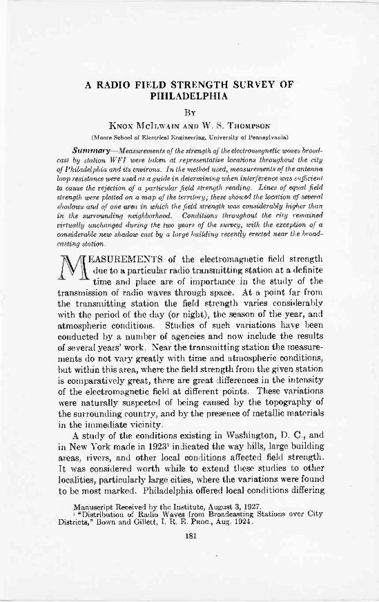
A RADIO FIELD STRENGTH SURVEY OFPHILADELPHIA
BY
KNOX MCILWAIN AND W. S. THOMPSON(Moore School of Electrical Engineering, University of Pennsylvania)
Summary-Measurements of the strength of the electromagnetic waves broad-cast by station W F I were taken at representative locations throughout the cityof Philadelphia and its environs. In the method used, measurements of the antennaloop resistance were used as a guide in determining when interference was sufficientto cause the rejection of a particular field strength reading. Lines of equal fieldstrength were plotted on a map of the territory; these showed the location of severalshadows and of one area in which the field strength was considerably higher thanin the surrounding neighborhood. Conditions throughout the city remainedvirtually unchanged during the two years of the survey, with the except2:on of aconsiderable new shadow cast by a large building recently erected near the broad-casting station.
MEASUREMENTS of the electromagnetic field strengthdue to a particular radio transmitting station at a definitetime and place are of importance in the study of the
transmission of radio waves through space. At a point far fromthe transmitting station the field strength varies considerablywith the period of the day (or night), the season of the year, andatmospheric conditions. Studies of such variations have beenconducted by a number of agencies and now include the resultsof several years' work. Near the transmitting station the measure-ments do not vary greatly with time and atmospheric conditions,but within this area, where the field strength from the given stationis comparatively great, there are great differences in the intensityof the electromagnetic field at different points. These variationswere naturally suspected of being caused by the topography ofthe surrounding country, and by the presence of metallic materialsin the immediate vicinity.
A study of the conditions existing in Washington, D. C., andin New York made in 1923' indicated the way hills, large buildingareas, rivers, and other local conditions affected field strength.It was considered worth while to extend these studies to otherlocalities, particularly large cities, where the variations were foundto be most marked. Philadelphia offered local conditions differing
Manuscript Received by the Institute, August 3, 1927.1 "Distribution of Radio Waves from Broadcasting Stations over City
Districts," Bown and Gillett, I. R. E. PROC., Aug. 1924.
181
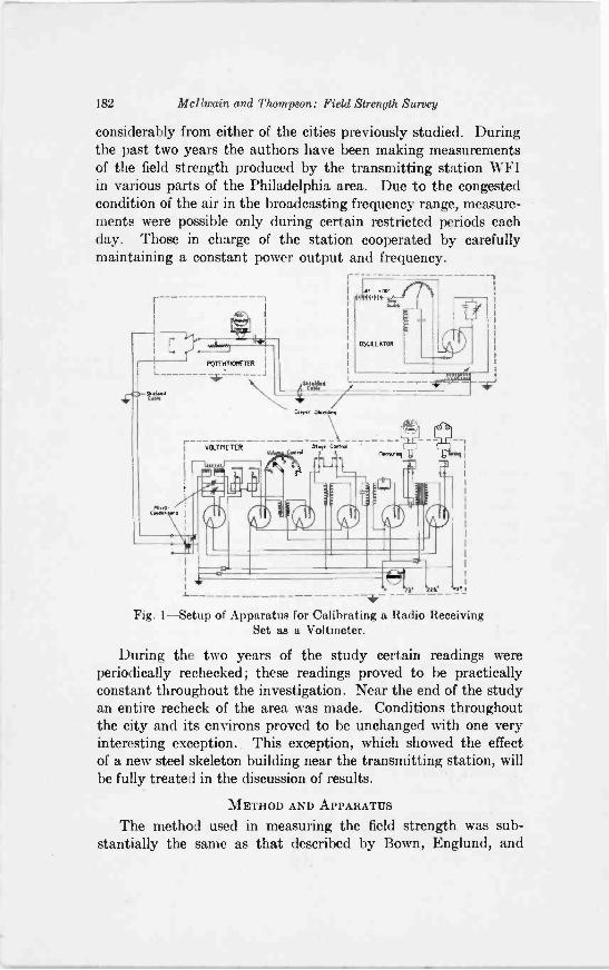
182 Mcllwain and Thompson: Field Strength Survey
considerably from either of the cities previously studied. Duringthe past two years the authors have been making measurementsof the field strength produced by the transmitting station WFIin various parts of the Philadelphia area. Due to the congestedcondition of the air in the broadcasting frequency range, measure-ments were possible only during certain restricted periods eachday. Those in charge of the station cooperated by carefullymaintaining a constant power output and frequency.
L
4.C. Se.td
I
POTEMMOMETER
74 ---j
VOLTMETER
Cyr. 41.14.9
"!I Cr.
Mlle NS. I
4r-Fig. 1-Setup of Apparatus for Calibrating a Radio Receiving
Set as a Voltmeter.
During the two years of the study certain readings wereperiodically rechecked; these readings proved to be practicallyconstant throughout the investigation. Near the end of the studyan entire recheck of the area was made. Conditions throughoutthe city and its environs proved to be unchanged with one veryinteresting exception.. This exception, which showed the effectof a new steel skeleton building near the transmitting station, willbe fully treated in the discussion of results.
METHOD AND APPARATUS
The method used in measuring the field strength was sub-stantially the same as that described by Bown, Englund, and
.
Mattwain and Thompson: Field Strength Survey 183
Friis.2 In the methods used by these investigators each readingwas obtained by noting the change in direct -plate current of adetector tube caused by an incoming carrier wave. The incomingcarrier was then eliminated, and a local oscillator used to impressa known variable voltage on the set. By adjusting the local voltageto cause the same variation in detector -plate current as given bythe incoming carrier, the voltage, and by calculation the verticalcomponent of the field intensity of the incoming signal was ob-tained. The voltage impressed across the input of a radio receiving
11
I0
5
1
6
5
.4452: 4
Te
_Is. 25
'a2
1.5
STEP
Y32-22-1
11
ill1_,
FAWN
1:151.7
30
eta,45.0
1 I
:4,- E .4:..1.13 "` *...;-..7, ri V Li 2F,;'Plafe Curren+- Milliamperes
Fig. 2-Calibrating Curve of Receiving Set.
set by a given electromagnetic field depends on the effective heightof the antenna used. The units of field intensity are volts, orfractions thereof, per meter.
The main difference in the method employed in the presentinvestigation was that a set, consisting of a standard six tubesuperheterodyne receiver and loop antenna, was calibrated as avoltmeter in the laboratory before being used in the field (Fig. 1).The change in direct -plate current of the second detector tubedue to a known voltage of a local oscillator was noted, and curveswere plotted of plate current reading against impressed voltage(Fig. 2). Many calibrations were made at first to insure thereliability of the curves. It was soon found that the calibrationwas quite stable, changing only as the detector tube and platebatteries aged. From then on occasional check calibrations weremade.
"Radio Transmission Measurements," Bown, Englund, and Friis,I. R. E. PROC., April 1923.
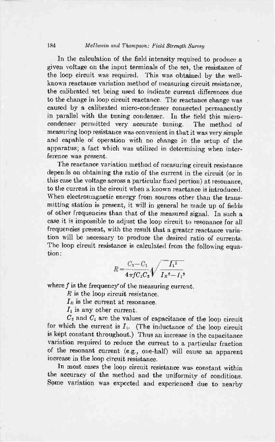
184 Mcllwain and Thompson: Field Strength Survey
In the calculation of the field intensity required to produce agiven voltage on the input terminals of the set, the resistance ofthe loop circuit was required. This was obtained by the well-known reactance variation method of measuring circuit resistance,the calibrated set being used to indicate current differences dueto the change in loop circuit reactance. The reactance change wascaused by a calibrated micro -condenser connected permanentlyin parallel with the tuning condenser. In the field this micro -condenser permitted very accurate tuning. The method ofmeasuring loop resistance was convenient in that it was very simpleand capable of operation with no change in the setup of theapparatus; a fact which was utilized in determining when inter-ference was present.
The reactance variation method of measuring circuit resistancedepends on obtaining the ratio of the current in the circuit (or inthis case the voltage across a particular fixed portion) at resonance,to the current in the circuit when a known reactance is introduced.When electromagnetic energy from sources other than the trans-mitting station is present, it will in general be made up of fieldsof other frequencies than that of the measured signal. In such acase it is impossible to adjust the loop circuit to resonance for allfrequencies present, with the result that a greater reactance varia-tion will be necessary to produce the desired ratio of currents.The loop circuit resistance is calculated from the following equa-tion:
R -C2-C2 /1
47rfCiC2 IR!-.112
2
where f is the frequency' of the measuring current.R is the loop circuit resistance../R is the current at resonance.Il is any other current.C, and C1 are the values of capacitance of the loop circuit
for which the current is /1. (The inductance of the loop circuitis kept constant throughout.) Thus an increase in the capacitancevariation required to reduce the current to a particular fractionof the resonant current (e.g., one-half) will cause an apparentincrease in the loop circuit resistance.
In most cases the loop circuit resistance was constant withinthe accuracy of the method and the uniformity of conditions.Some variation was expected and experienced due to nearby
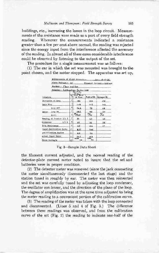
Mcllwain and Thompson: Field Strength. Survey 185
buildings, etc., increasing the losses in the loop circuit. Measure-ments of the resistance were made as a part of every field strengthreading. Whenever the measurements indicated a resistancegreater than a few per cent above normal, the reading was rejectedsince the energy input from the interference affected the accuracyof the reading. In almost all of these cases considerable interferencecould be observed by listening to the output of the set.
The procedure for a single measurement was as follows:(1) The car in which the set was mounted was brought to the
point chosen, and the motor stopped. The apparatus was set up,Measurement. of Yield Strength.- _Cete...0 -17-2g
Plate Voltage:- 4V
Weather:- Near and Nat
711emont Current - a.25 ant
a..re.: - Leotonencapn
Lentotlow
norrer 0../131a.o7..n
tai: ..
1 ..... IL:. Avele kitux . 3 Stries .
Dlreotion of Loop 2 R, 1t0 laS
Clain Step 3 1-4 I -5 1-4
Loop off 4 745 Tb fis
&tar Loon on 5 ELS 40
5
4
Dtff: 6 35/4 1.s51.y
74S
Reading of Vernier 1/2 1 7 5$ 65 63
Condenser 1/2 1 6 27 56 20
Loop Resistance 9 117 II f. 17
Input -Calibration Curve 10 air 745
amplification Factor 11 aa 21
actual Input Volts 12 gaw 144
rieid Strength 13 tee""tealma aS
Fig. 3-Sample Data Sheet
the filament current adjusted, and the normal reading of thedetector -plate current meter noted to insure that the set andbatteries were in proper condition.
(2) The detector meter was removed (since the jack connectingthe meter simultaneously disconnected the last stage) and thestation tuned in roughly by ear. The meter was then reinsertedand the set was carefully tuned by adjusting the loop condenser,the oscillator condenser, and the direction of the plane of the loop.The degree of amplification was at the same time adjusted to bringthe meter reading to a convenient portion of the calibration curve.
(3) The reading of the meter was taken with the loop connectedand disconnected. (Lines 5 and 4 of Fig. 3.) The differencebetween these readings was observed, and from the calibrationcurve of the set (Fig. 2) the reading to indicate one-half of the
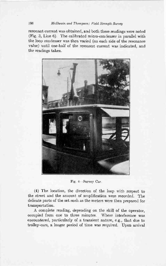
186 Mcllwain and Thompson: Field Strength Survey
resonant current was obtained, and both these readings were noted(Fig. 3, Line 6). The calibrated micro -condenser in parallel withthe loop condenser was then varied (on each side of the resonancevalue) until one-half of the resonant current was indicated, andthe readings taken.
Fig. 4-Survey Car.
(4) The location, the direction of the loop with respect tothe street and the amount of amplification were recorded. Thedelicate parts of the set such as the meters were then prepared fortransportation.
A complete reading, depending on the skill of the operator,occupied from one to three minutes. Where interference wasencountered, particularly of a transient nature, e.g., that due totrolley -cars, a longer period of time was required. Upon arrival
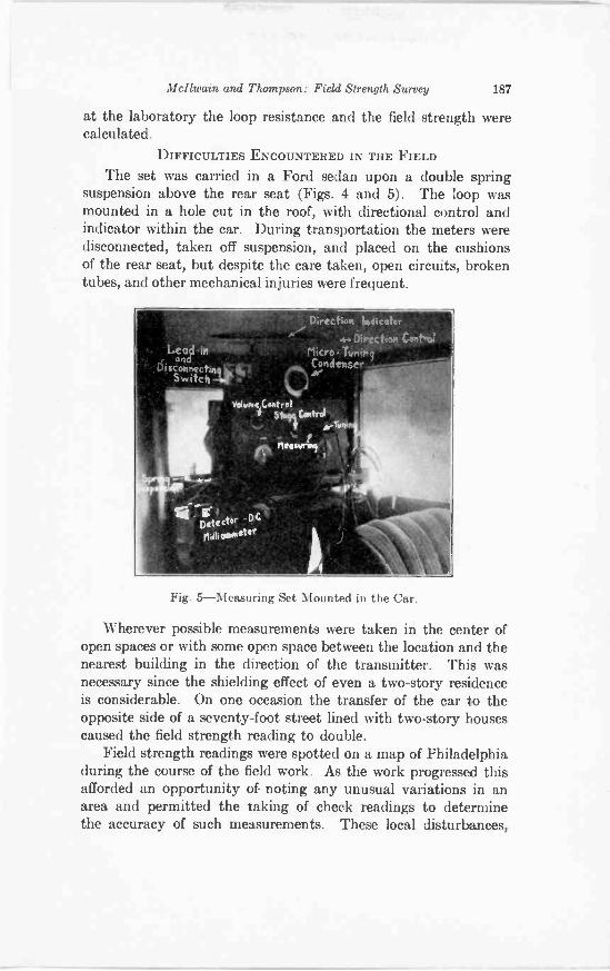
Mcllwain and Thompson: Field Strength Survey 187
at the laboratory the loop resistance and the field strength werecalculated.
DIFFICULTIES ENCOUNTERED IN THE FIELD
The set was carried in a Ford sedan upon a double springsuspension above the rear seat (Figs. 4 and 5). The loop wasmounted in a hole cut in the roof, with directional control andindicator within the car. During transportation the meters weredisconnected, taken off suspension, and placed on the cushionsof the rear seat, but despite the care taken, open circuits, brokentubes, and other mechanical injuries were frequent.
Fig. 5-Measuring Set Mounted in the Car.
Wherever possible measurements were taken in the center ofopen spaces or with some open space between the location and thenearest building in the direction of the transmitter. This wasnecessary since the shielding effect of even a two-story residenceis considerable. On one occasion the transfer of the car to theopposite side of a seventy-foot street lined with two-story housescaused the field strength reading to double.
Field strength readings were spotted on a map of Philadelphiaduring the course of the field work. As the work progressed thisafforded an opportunity of noting any unusual variations in anarea and permitted the taking of check readings to determinethe accuracy of such measurements. These local disturbances,
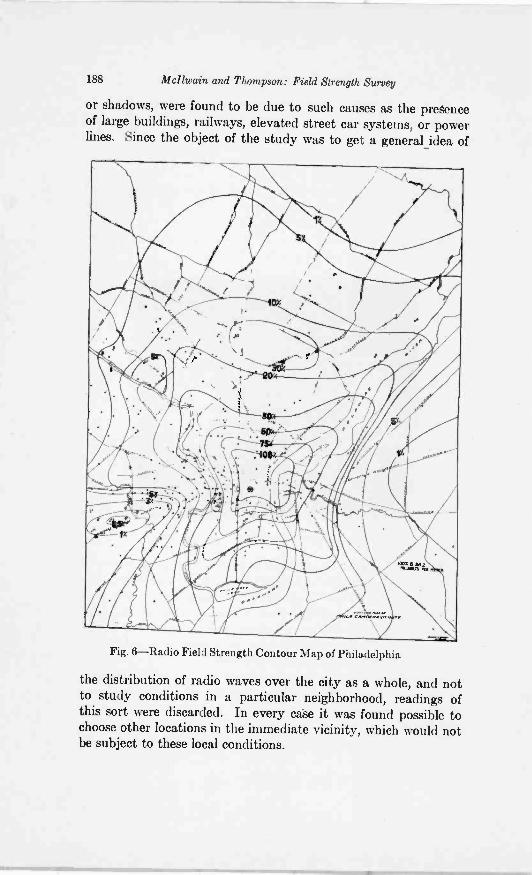
188 Mcllwain and Thompson: Field Strength Survey
or shadows, were found to be due to such causes as the presenceof large buildings, railways, elevated street car systems, or powerlines. Since the object of the study was to get a general idea of
Fig. 6-Radio Field Strength Contour Map of Philadelphia
the distribution of radio waves over the city as a whole, and notto study conditions in a particular neighborhood, readings ofthis sort were discarded. In every case it was found possible tochoose other locations in the immediate vicinity, which would notbe subject to these local conditions.
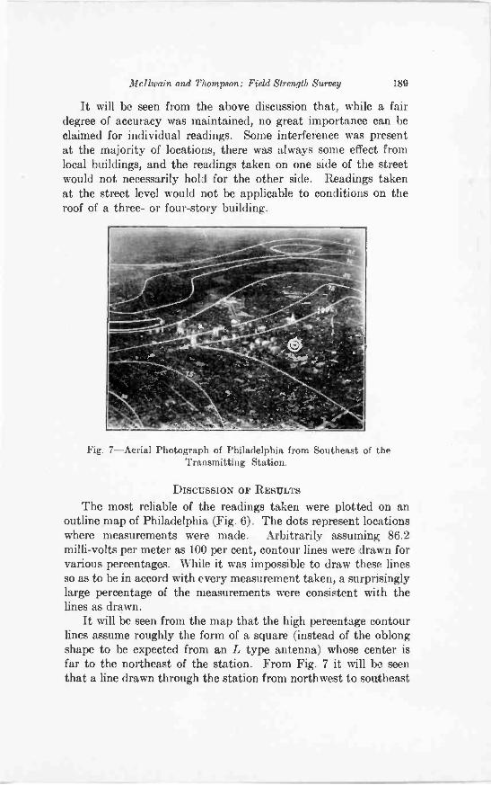
Mcllwain and Thompson: Field Strength Survey 189
It will be seen from the above discussion that, while a fairdegree of accuracy was maintained, no great importance can beclaimed for individual readings. Some interference was presentat the majority of locations, there was always some effect fromlocal buildings, and the readings taken on one side of the streetwould not necessarily hold for the other side. Readings takenat the street level would not be applicable to conditions on theroof of a three- or four-story building.
Fig. 7-Aerial Photograph of Philadelphia from Southeast of theTransmitting Station.
DISCUSSION OF RESULTS
The most reliable of the readings taken were plotted on anoutline map of Philadelphia (Fig. 6). The dots represent locationswhere measurements were made. Arbitrarily assuming 86.2milli -volts per meter as 100 per cent, contour lines were drawn forvarious percentages. While it was impossible to draw these linesso as to be in accord with every measurement taken, a surprisinglylarge percentage of the measurements were consistent with thelines as drawn.
It will be seen from the map that the high percentage contourlines assume roughly the form of a square (instead of the oblongshape to be expected from an L type antenna) whose center isfar to the northeast of the station. From Fig. 7 it will be seenthat a line drawn through the station from northwest to southeast
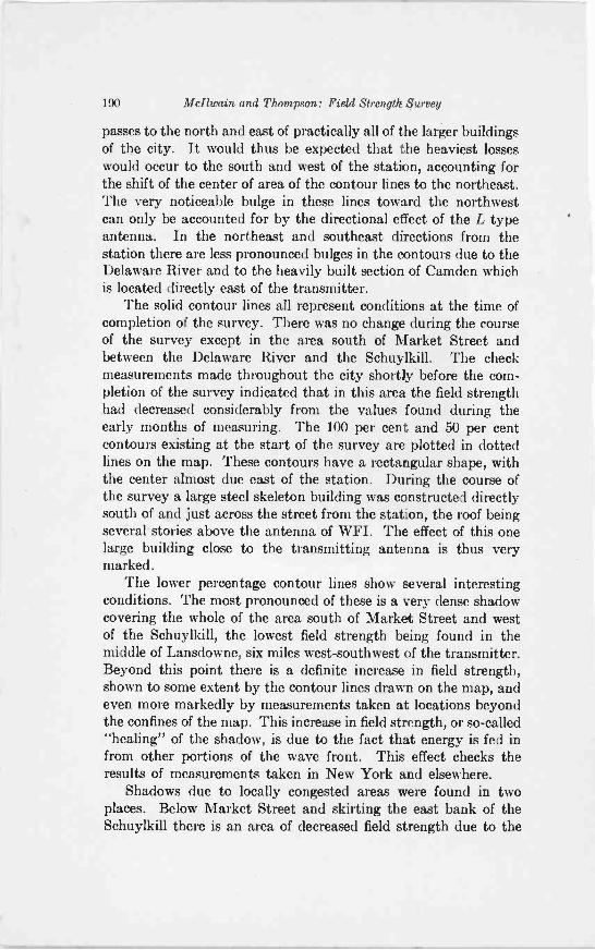
190 Meltwain and Thompson: Field Strength Survey
passes to the north and east of practically all of the larger buildingsof the city. It would thus be expected that the heaviest losseswould occur to the south and west of the station, accounting forthe shift of the center of area of the contour lines to the northeast.The very noticeable bulge in these lines toward the northwestcan only be accounted for by the directional effect of the L typeantenna. In the northeast and southeast directions from thestation there are less pronounced bulges in the contours due to theDelaware River and to the heavily built section of Camden whichis located directly east of the transmitter.
The solid contour lines all represent conditions at the time ofcompletion of the survey. There was no change during the courseof the survey except in the area south of Market Street andbetween the Delaware River and the Schuylkill. The checkmeasurements made throughout the city shortly before the com-pletion of the survey indicated that in this area the field strengthhad decreased considerably from the values found during theearly months of measuring. The 100 per cent and 50 per centcontours existing at the start of the survey are plotted in dottedlines on the map. These contours have a rectangular shape, withthe center almost due east of the station. During the course ofthe survey a large steel skeleton building was constructed directlysouth of and just across the street from the station, the roof beingseveral stories above the antenna of WFI. The effect of this onelarge building close to the transmitting antenna is thus verymarked.
The lower percentage contour lines show several interestingconditions. The most pronounced of these is a very dense shadowcovering the whole of the area south of Market Street and westof the Schuylkill, the lowest field strength being found in themiddle of Lansdowne, six miles west-southwest of the transmitter.Beyond this point there is a definite increase in field strength,shown to some extent by the contour lines drawn on the map, andeven more markedly by measurements taken at locations beyondthe confines of the map. This increase in field strength, or so-called"healing" of the shadow, is due to the fact that energy is fed infrom other portions of the wave front. This effect checks theresults of measurements taken in New York and elsewhere.
Shadows due to locally congested areas were found in twoplaces. Below Market Street and skirting the east bank of theSchuylkill there is an area of decreased field strength due to the
Mcllwain and Thompson: Field Strength Survey 191
presence of a group of factory and business buildings. Northwestof the station, between the 10 and 20 per cent lines, there is alarger area of decreased field strength due to the congested buildingarea of Manayunk.
East of the Delaware River the shadow of the heavily builtarea of Camden is quite well marked. This shadow is nearly asdense but not so clearly defined as that in West Philadelphia.
Directly north of the station in the vicinity of the RooseveltBoulevard between the 10 and 20 per cent lines there is an areaof increased field strength. This would be expected from the fact
Fig. 8-Aerial Photograph of Philadelphia and Camden; West of Transmit-ting Station.
that in this vicinity there are only occasional groups of two-storyhouses, dotting a large area of open fields.
Whenever open country or rivers were encountered local bulgesare found in the contour lines, indicating the decreased losses oversuch areas. This tendency of the lines is especially marked alongthe Delaware River northeast of the station; here the measure-ments taken as nearly on the river bank as possible indicate fieldstrengths 50 to 100 per cent greater than those taken about amile inshore. The percentages found at several of the locationsin this area were noted on the map to illustrate this tendency.
All of the effects found above are consistent with existingtheories of transmission. The pattern found for Philadelphia is
192 McItwain and Thompson: Field Strength Survey
quite different from those of New York and Washington. Whilethe New York pattern is characterized by its dumbbell shapeand the Washington pattern by a circle, the Philadelphia patternis roughly square, with its center far from the station. Other citieswill undoubtedly exhibit equally interesting characteristicpatterns.
ACKNOWLEDGMENT
The authors' thanks are due to the American Telephone andTelegraph Company not only for the loan of the equipment usedin the measuring work, but also for advice and guidance receivedfrom its engineers. Thanks are also due to the Strawbridge andClothier Company for cooperation in the actual measurements.
ON THE THEORY OF POWER AMPLIFICATION*
BY
MANFRED VON ARDENNE(Berlin)
Summary -1. In order to supply a maximum output wattageto an inductiveloudspeaker by means of high -power tubes, regardless of the necessary amplitude ofE5, it is necessary to calculate the plate battery and grid -biasing potentials requiredto ensure distortionless reproduction.
2. From the inductive load on the plate circuit of the tube an elliptical shapeof the working characteristic follows, referring to the eosin diagram.
3. If the working ellipse is enclosed by a rectangular quadrangle, the sides ofwhich are parallel to abscissa and ordinate axes respectively, then the slope orangle an, of the diagonal of this quadrangle means the dynamic slope or mutualconductance of the tube for the given plate -circuit load, for
=Eg
4. By means of as,, and starting from the conditions of distortionless reproduc-tion the position of the diagonal of the quadrangle and its useful part are deter-mined and furthermore the following equations for the minimum necessary plate -battery potential as well as for the necessary grid -biasing potential are found:
1B= K -FI ,(r, -F Re) + / 0.014' (r,1 - g m .
Ec =E[;5. It is shown what conditions result if several loudspeakers are connected
in series or in parallel with each other or if several tubes connected in parallel areemployed to supply the loudspeaker.
6. Calculated and graphical solutions of the problem in question are givenfor practical examples and especially curves are shown illustrating the depen-dence of the effective output wattage of the loudspeaker on thei nternal plate resis-tance of the tube and on the operating frequency.
I. PROBLEM AND CONDITIONS
WHEN it becomes desirable to obtain a maximum dis-tortionless output of sound from a system of loudspeakersby means of a power -tube, then the question of calculating
the necessary d -c. plate- and grid -potentials arises.The condition of freedom from distortion comprises:First, that in no case should the effective grid -potential of the
tube, that is the d -c. grid -bias plus the impressed a -c. potential,reach the region of either appreciable grid -current or appreciable
Original Manuscript Received by the Institute, November 2, 1927. Re -written in accordance with M. v. Ardenne, "Zur Theorie der
Endverstarkung", Jahrbuch, Band 30, Heft 3.
193
194 von Ardenne: Power Amplification
curvature of the static tube characteristics; and, secondly, thatthe system of loudspeakers used should be capable of convertingthe impressed audio -frequency impulses into sound withoutdistortion.
Furthermore, the condition is assumed to be fulfilled, as inpractice is nearly always the case, that the preceding apparatusis capable of delivering any necessary amount of a -c. potentialto the power -tube.
Roughly the load on the plate -circuit of the power -tube inducedby the system of loudspeakers may be assumed to consist of aninductance L and an effective resistance Rb.. This effective re-sistance Rbm consists of the pure ohmic resistance Rb of the loud-speaker coils and the working resistance R., which itself againcomprises both the losses resistance and the useful acousticradiation resistance R.'.
II. THE PLATE -CURRENT
For the sake of simplicity it will be assumed that the power -tube is required to supply only a single loudspeaker.
The momentary plate -current then results from the steadydirect plate -current and an a -c. value as indicated by:
= /-Fi; (1)
The steady direct plate -current may be taken to be:
RBI(Ec-1- ) = crp -rp TB')I p=cr, rp+ Re
Ec-1-
In this formula crp, designates the mutual conductance of theworking characteristic, le the d -c. grid -biasing potential andRe'the potential of the plate -potential battery, diminished by acorrection potential K.
Furthermore
tp=/,sin(co- t- IP)
(2)
(3)
can be written, if the impressed a -c. potential on the grid is sinu-soidal, from which an also sinusoidal alternating plate-currentfollows. Since the tube may be looked upon as an a -c. generator
1 R is in practice not absolutely constant, but changes according to thetype of loudspeaker and is mainly dependent on the special resonance peaks ofthe latter. In the following R will be assumed to be constant, since for theusual loud -speaker -effectiveness its value may safely be disregarded.
von Ardenne: Power Amplification 195
with the e.m.f. or load -less potential A Eg, where Eg means theamplitude of the a -c. potential impressed on the grid,
AL Eg(4)
V(cu L)2+ (r-I-Rb,)2
follows; the denominator designates the impedance of the generatorcircuit. Finally the phase -angle between the plate -current andthe grid -potential is given by
(r :/?Lb,)
Thus the following final formula for the plate -current results:
i -FFB')+ Eg -
rp+ Rb e A (ta 42+(rp-FE6)2
r,
sin[(cot) - arc tgrr
( w )1 (6)r1- Rb,,
III. THE WORKING CHARACTERISTIC
By means of
or
= arc tg
lg=L-FE. sin (cut)
sin ((AO--E.
may be changed to define the relation between i, and lg. For thesake of simplicity the letter a will be written instead of co 1.
(5)
(7)
(8)
sin (a - = sin a cos -N/1- sin2a sin 4, (9)
4,igE -Rey
= cos sin0/1/1 (10)
lg-R, co L
Ow L)2-1-(rp-FRQ2 Eg Ow L)2+ (rp-I-R6)2
xVE.2- (lg-E`)2Eg
196 von Ardenne: Power Amplification
From these equations the following results:
Ea'ip = O'pr (E, d--)+
[(0)42 (rp+Rbw)2i[(r + Raw) (12 - Pc)
which may also be written thus:
-wL V E (1g -R)21 (12)
y =A[ax-b (13)
if the following substitutions are carried out:
[(co L)2+ (r, -F 14,0)2]-A; coL=b;
rp+Raw = a ; lg-Ec=x; i,-1,=y. (14)
Since equation (13) can be brought into the form of the centralequation of an ellipse
ai,x2+2.ai,x y±a2, y2 = k (15)
by means of the substitutions
al,=A2. (a2d-b2)[(coL)2-1- (r -Ra.)2]
- (r, -F Raw) ual,- A a - a2, = 1 ; (16)
RwL)2+ (rp-1- w)2]
R = A2* b2 E 2 =Eg2 (6102
[(coL)2+ (r -Raw)212
it becomes apparent that the working characteristic of the tubefor an inductive and ohmic load of the plate circuit is not a straightline, but, according to equation (12), an ellipse the axes of whichform angles with the abscissa lg and the ordinate
and
IV. THE RECTANGULAR QUADRANGLE ENCLOSING THEWORKING CHARACTERISTICS
This formula leads, as will be shown in the following, to theequations desired expressing the necessary d -c. plate and gridpotentials, if it is brought into relation with the conditions ofthe problem here under discussion which were stated above.
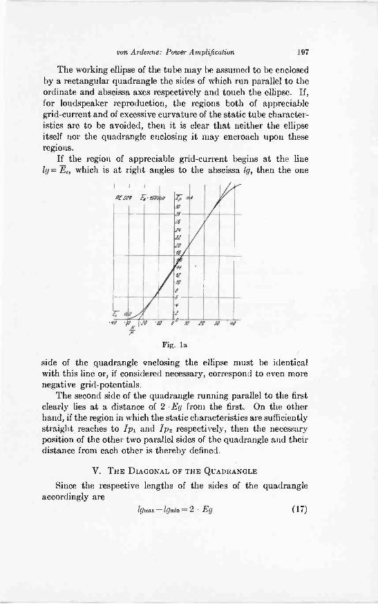
von Ardenne: Power Amplification 197
The working ellipse of the tube may be assumed to be enclosedby a rectangular quadrangle the sides of which run parallel to theordinate and abscissa axes respectively and touch the ellipse. If,for loudspeaker reproduction, the regions both of appreciablegrid -current and of excessive curvature of the static tube character-istics are to be avoided, then it is clear that neither the ellipseitself nor the quadrangle enclosing it may encroach upon theseregions.
If the region of appreciable grid -current begins at the line1g=Ec, which is at right angles to the abscissa lg, then the one
'fief 1->50 7;JO
16
16
2210fe
-'a
10
6
4,
00 /0
Fig. la
16 30 #0
side of the quadrangle enclosing the ellipse must be identicalwith this line or, if considered necessary, correspond to even morenegative grid -potentials.
The second side of the quadrangle running parallel to the firstclearly lies at a distance of 2 Eg from the first. On the otherhand, if the region in which the static characteristics are sufficientlystraight reaches to /pi and Ip2 respectively, then the necessaryposition of the other two parallel sides of the quadrangle and theirdistance from each other is thereby defined.
V. THE DIAGONAL OF THE QUADRANGLE
Since the respective lengths of the sides of the quadrangleaccordingly are
/glen - /grain = 2 Eg (17)
198 von Ardenne: Power Amplification
and
17, = ipm a X ipm n\/(a.) L)2+ (rp-1- R6)2
the diagonal of the quadrangle which passes through the pointEG; I pi forms an angle with the abscissa lg, which may be expressedas follows:
(18)
r,IP.= = (19)
V(wL)2+(rp-I-Rbeg)2 V(coL)2±(r9-1-Rbeg)2 Eg
This angle here is expressed in the form of a mutual con-ductance, because, as will be shown later, the diagonal may withgreat advantage be assumed to be the working characteristic ofthe tube for an inductive and ohmic load on the plate -circuit,instead of the ellipse. The center of the ellipse and therefore also
that of the enclosing quadrangle is the point E41, = /p, +2
therefore this point also lies on the diagonal, which thereforepossesses the equation
iP = pz (19 (20)
By means of equation (2) this may be changed to the followingform:
±YBT)17Pr I
VI. THE MATHEMATICAL SOLUTION OF THE PROBLEM
Now the point with the abscissa
ig=Egand the ordinate
(21)
also belongs to the diagonal. If these values are substituted intoequation (21), then after some operations the following formularesults:
EDI = Ip (rp+Rto)-Fip' V(COL)2+ (rp+R&40)2 EC' (22)
Thus also:
= K-F p(rp-F Rb)d- V (wL)2+ (r,+ Rb.)2 Eg (22a)
von Ardenne: Power Amplification 199
/Pi + ip2If the values Ea, I,, = and /,, together with those of µ,
2r,,, and K are taken from the static tube characteristics and further-more if the values LiRe and Rb. are known as the data of theloudspeaker in question, then the formula above supplies thedesired value for the minimum amount of plate -battery potentialnecessary to meet the working conditions of the tube which werediscussed above.
Furthermore, by means of
_ r; Ey/3'E,*= -a Pr A
(23)
this equation for Ea' leads to the following formula for thenecessary d -c. grid -potential:
I,E, = Ea -- 1/(coL)2+ (r p- I -140)2 (25)
The a -c. potential impressed on the grid then must not exceedthe value
E, =I p
V (coL)2+ (r p+ Rb,)2IA
(26)
For co a value of about 2ir 800 =5,000 may be assumed, ifthe fact is taken into consideration that at the higher frequencies,with music as well as speech, the amplitudes of the impressed a -c.potentials are correspondingly smaller than at lower frequencies.The higher the frequency, the smaller the slope (mutual con-ductance) of the diagonal of the quadrangle which encloses theworking ellipse becomes; and correspondingly smaller plate currentvariations are the result. If, as said above, the impressed a -c.potential amplitudes are greatest at a frequency of 800 Hertz,then in practice all those working curves for frequencies smallerthan 800 must lie within the working ellipse for the frequencyof 800 Hertz.
For the calculation of Ec, however, a value corresponding tothe smallest frequency in question must be assumed for w, aboutw = 2r 16 =100. Otherwise at these low frequencies the impresseda -c. potentials on the grid would reach the regions where the tube
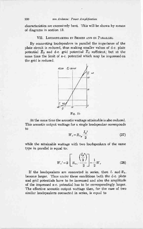
200 von Ardenne: Power Amplification
characteristics are excessively bent. This will be shown by meansof diagrams in section 13.
VII. LOUDSPEAKERS IN SERIES AND IN PARALLEL
By connecting loudspeakers in parallel the impedance of theplate circuit is reduced, thus making smaller values of d -c. platepotential Ea and d -c. grid potential Ec sufficient; but at thesame time the limit of a -c. potential which may be impressed onthe grid is reduced.
Fig. lb
At the same time the acoustic wattage attainable is also reduced.This acoustic output wattage for a single loudspeaker correspondsto
1,2W,=R,, -
P 2(27)
while the attainable wattage with two loudspeakers of the sametype in parallel is equal to:
= 2 [R,2)]- 1
2IV (28)-
If the loudspeakers are connected in series, then L and Rbobecome larger. Thus under these conditions both the d -c. plateand grid potentials have to be increased and also the amplitudeof the impressed a -c. potential has to be correspondingly larger.The effective acoustic output wattage then, for the case of twosimilar loudspeakers connected in series, is equal to
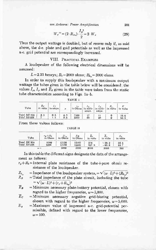
von Ardenne: Power Amplification 201
1,2TV," = (2 li.)
2-= 2 W, (29)
Thus the output wattage is doubled, but of course only if, as saidabove, the d -c. plate and grid potentials as well as the impresseda -c. grid potential are correspondingly increased.
VIII. PRACTICAL EXAMPLES
A loudspeaker of the following electrical dimensions will beassumed:
L =2.35 henrys; Rb= 2000 ohms; Rbw= 3000 ohms.In order to supply this loudspeaker with a maximum output
wattage the tubes given in the table below will be considered; thevalues 1,, I, and EG given in the table were taken from the statictube characteristics according to Figs. la -b.
TABLE I
Tube in volts in amps. s in Ohms in milli-amps.
in milli-amps.
in volts in volts
Telef. RE 504Telef. RS 228
3.57
0.51.1
4.55.5
75003200
1760
1140
00
38.683.5
values follows:TABLE II
rp+Rbin Ohms
,,,in Ohms
1213012130
Ohmsin Ohms inin volts
374927.5
,in volts in voltsvolts
Telef.Telef. RE 504Telef. RS 228
95005200
1576013300
*-38.2-95.8
25.444.7
5000 5000 5000 5000
In this table the different signs designate the data of the arrange-ment as follows:rp-I-Rb = Internal plate resistance of the tube+pure ohmic re-
sistance of the loudspeaker.Zbw = Impedance of the loudspeaker system, .V= (co . L)2 + MO 2
ZB =Total impedance of the plate circuit, including the tube= V(co L)2-1- (r,-
EB = Minimum necessary plate -battery potential, chosen withregard to the higher frequencies, w = 5,000.
Ec = Minimum necessary negative grid -biasing potential,chosen with regard to the higher frequencies, w = 5,000.
E, = Maximum value of impressed a -c. grid -potential per-missible, defined with regard to the lower frequencies,co =100.
202 von Ardenne: Power Amplification
IX. THE USE OF SEVERAL POWER TUBESCONNECTED IN PARALLEL
According to the above calculations a clearly defined minimumplate -battery potential is necessary to obtain a maximum outputwattage from a given power -tube to a given loudspeaker. Thisfact might lead to the false assumption that, in order to obtainan equal output wattage it would be possible to substitute anumber of smaller tubes connected in parallel for a single butlarger power -tube and at the same time using less plate -batterypotential for the several smaller tubes.
If it is assumed that n similar, smaller tubes are connected inparallel, each one of which possesses the data Rf', 1/, Ai', rp',Ip', K', then these tubes correspond to a single hypotheticaltube of the following electrical dimensions:
r,/i=n//, µ=µ', r,= p, Ip=nIp', K=K'n
In this case the different electrode -systems may be assumed tobe enclosed in a single evacuated glass tube.
The necessary plate -battery potential for the n power tubesconnected in parallel then is
r 'EB=K'-l-n I' e--1-Rb) n I Pt (C L)2 + + Row)2 (30)
For example, with four tubes RE 504 arranged in this mannerand with the following electrical dimensions of the circuit
L = 2.35 henrys; Rb = 2,000 ohms; Rb.= 3,000 ohmsthe necessary value of plate -battery potential resulting would be861 volts. The output current of these four tubes is /p =4.17=68 mA and 4=4.11 = 44 mA for a filament wattage consumptionof 4 -3.5 -0.5=7 watts. About the same output current is suppliedby a single tube of the type RS 228, namely /,,=60 mA and I=40 mA, for a filament consumption of approximately the samevalue, namely 7 -1.1 =7.7 watts. This tube requires a minimumplate -battery potential of 927.5 volts according to Table II.
X. THE DEPENDENCE OF THE PLATE CURRENT AND USEFULOUTPUT WATTAGE FROM THE INTERNAL PLATE RESISTANCE
OF THE TUBE AND FROM THE OPERATING FREQUENCY
If the load on the plate circuit, that is the values L, Rb, andRb,. of the loudspeaker system, is assumed to be constant andpredetermined, then the plate -current is, if a certain amplitude
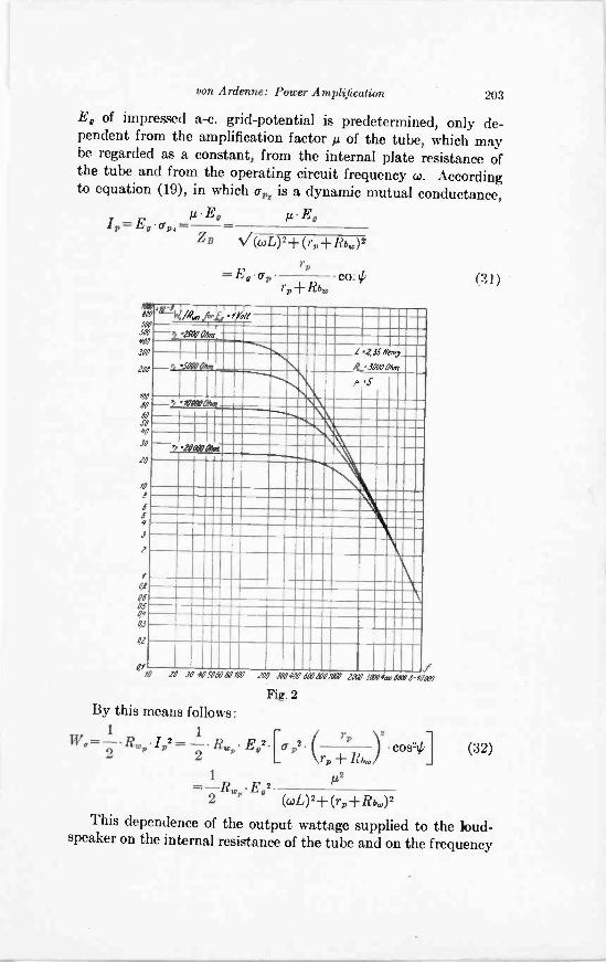
von Ardenne: Power Amplification 203
E, of impressed a -c. grid -potential is predetermined, only de-pendent from the amplification factor tc of the tube, which maybe regarded as a constant, from the internal plate resistance ofthe tube and from the operating circuit frequency w. Accordingto equation (19), in which cr, is a dynamic mutual conductance,
µ E, A -EDIp= E, cr,,- -
Z B ((Ay+ (r p- F Rb)2
r,=E,cr, co # (31)
OWSW#A7
300
IN
m7aN
SOSI
30
10
40
08
6a4
3
14?
4545
42
4WOhni
.2,1f1May
R,..1000dan
p- .104701Mot
20000a %m
20 30 00506001M7 100 .141741V 61Nd8al IOW Jaffa 0-O0m
Fig. 2By this means follows:
1 1 / r,W°=-2-LPIP2 = LP. E°2pp2-L+RJ cos24] (32)
1 IA2=-R E 7922 (cuL)2+ (r-I-Rc,)2
This dependence of the output wattage supplied to the loud-speaker on the internal resistance of the tube and on the frequency
204 von Ardenne: Power Amplification
is shown for the values given in the above equations by a numberof curves in Fig. 2.
In judging these curves it must be borne in mind that they onlyrepresent the electrical output wattage supplied to the loudspeaker,which the latter converts into sound, but not the actual acousticair pressure amplitudes which are produced by the mechanicalvibrations of the loudspeaker diaphragm at different frequencies.The actual radiated sound amplitudes, however, increase withthe frequency in accordance with an approximately square lawfor equal amplitudes of mechanical vibration. This (if the lossesare disregarded) practically square law approximately correspondsto the opposite incline of the curves shown above at higherfrequencies and thus practically equal volume of sound is obtainedat the higher frequencies. At the lower frequencies, however,matters become much more complicated and will therefore notbe discussed here.
XI. A CONTRIBITTION TO THE DESIGNING OF TUBES FORPOWER -AMPLIFICATION PURPOSES
In order to design suitably a tube meant for power -amplificationone may start with the condition that for a certain plate -batterypotential ED a certain a -c. amplitude I,, is to be supplied to theloudspeaker. According to equation (22)
EB -K = I,, (rp-FRO + N/ (4)1)2+(fp+Riv)2
In this equation K is always defined with sufficient exactness forpreliminary calculations (refer to Table I) as
K=0.1 Fb.Furthermore
/, M /,.may be written and for M the value 1.5 may be substituted in thecase of high -power tubes and 2 in the case of tubes of ordinarydimensions.
By this means
yp=Mkrp-FRO-I-
0.9
10.0.02-1- (rp+Rbw)2 (33)
BEis found. Now if, as mentioned above, - is predetermined, if a.
/,
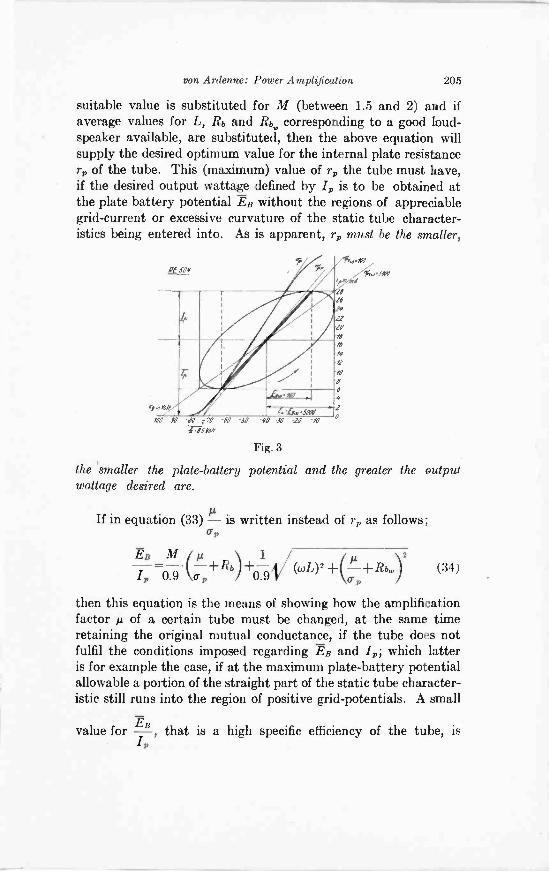
von Ardenne: Power Amplification 205
suitable value is substituted for M (between 1.5 and 2) and ifaverage values for L, Rb and Rb. corresponding to a good loud-speaker available, are substituted, then the above equation willsupply the desired optimum value for the internal plate resistancer, of the tube. This (maximum) value of r, the tube must have,if the desired output wattage defined by I,, is to be obtained atthe plate battery potential Ea without the regions of appreciablegrid -current or excessive curvature of the static tube character-istics being entered into. As is apparent, r, must be the smaller,
.as
I1P7AA%.SIN
42101NO JO
RE $04,
Fig. 3
the 'smaller the plate -battery potential and the greater the outputwattage desired are.
If in equation (33) is written instead of rp as follows;Up
Es M 1p+Rb +0.9V(coL)2 +(Li -1-Rbw)2/, 0.9 (34)
then this equation is the means of showing how the amplificationfactorµ of a certain tube must be changed, at the same timeretaining the original mutual conductance, if the tube does notfulfil the conditions imposed regarding ER and I; which latteris for example the case, if at the maximum plate -battery potentialallowable a portion of the straight part of the static tube character-istic still runs into the region of positive grid -potentials. A small
value for /-, that is a high specific efficiency of the tube, is,
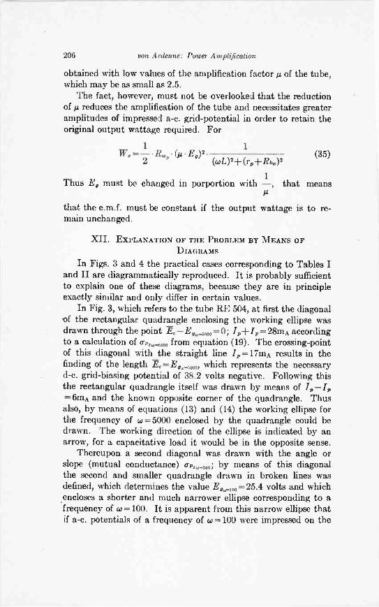
206 von Ardenne: Power Amplification
obtained with low values of the amplification factor la of the tube,which may be as small as 2.5.
The fact, however, must not be overlooked that the reductionof Ac reduces the amplification of the tube and necessitates greateramplitudes of impressed a -c. grid -potential in order to retain theoriginal output wattage required. For
1 1=2
/Li, OA E°)$ (.0L)2+ (rsi+REO)2
1Thus Eg must be changed in porportion with -, that means
(35)
that the e.m.f. must be constant if the output wattage is to re-main unchanged.
XII. EXPLANATION OF THE PROBLEM BY MEANS OFDIAGRAMS
In Figs. 3 and 4 the practical cases corresponding to Tables Iand II are diagrammatically reproduced. It is probably sufficientto explain one of these diagrams, because they are in principleexactly similar and only differ in certain values.
In Fig. 3, which refers to the tube RE 504, at first the diagonalof the rectangular quadrangle enclosing the working ellipse wasdrawn through the point Ec-E,,,_,p. =0; .7,-F/p= 28mA accordingto a calculation of ap,_,000 from equation (19). The crossing -pointof this diagonal with the straight line .1=17mA results in thefinding of the length Fc= Ead_oo., which represents the necessaryd -c. grid -biasing potential of 38.2 volts negative. Following thisthe rectangular quadrangle itself was drawn by means of I,-I,=6mA and the known opposite corner of the quadrangle. Thusalso, by means of equations (13) and (14) the working ellipse forthe frequency of w = 5000 enclosed by the quadrangle could bedrawn. The working direction of the ellipse is indicated by anarrow, for a capacitative load it would be in the opposite sense.
Thereupon a second diagonal was drawn with the angle orslope (mutual conductance) .c.,-100; by means of this diagonalthe second and smaller quadrangle drawn in broken lines wasdefined, which determines the value E,,,og=25.4 volts and whichencloses a shorter and much narrower ellipse corresponding to afrequency of co = 100. It is apparent from this narrow ellipse thatif a -c. potentials of a frequency of w =100 were impressed on the
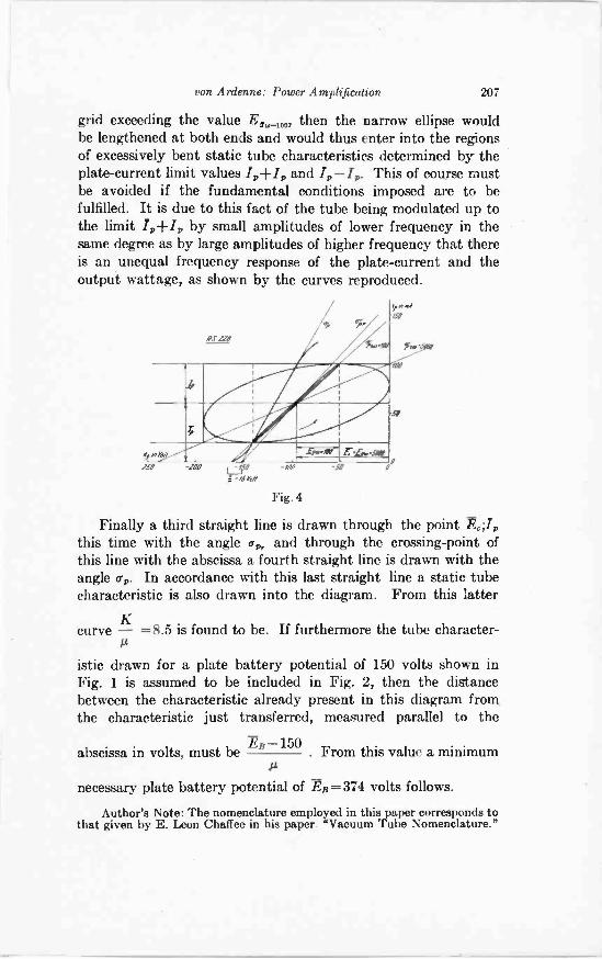
von Ardenne: Power Amplification 207
grid exceeding the value then the narrow ellipse wouldbe lengthened at both ends and would thus enter into the regionsof excessively bent static tube characteristics determined by theplate -current limit values and .4-4. This of course mustbe avoided if the fundamental conditions imposed are to befulfilled. It is due to this fact of the tube being modulated up tothe limit 41-.4 by small amplitudes of lower frequency in thesame degree as by large amplitudes of higher frequency that thereis an unequal frequency response of the plate -current and theoutput wattage, as shown by the curves reproduced.
'Till
iffirIKAMIff.4"/
/SO
Fig. 4
Finally a third straight line is drawn through the pointthis time with the angle e, and through the crossing -point ofthis line with the abscissa a fourth straight line is drawn with theangle up. In accordance with this last straight line a static tubecharacteristic is also drawn into the diagram. From this latter
curve - =8.5 is found to be. If furthermore the tube character-
istic drawn for a plate battery potential of 150 volts shown inFig. 1 is assumed to be included in Fig. 2, then the distancebetween the characteristic already present in this diagram fromthe characteristic just transferred, measured parallel to the
-150TBabscissa in volts, must be From this value a minimum
necessary plate battery potential of 2B = 374 volts follows.
Author's Note: The nomenclature employed in this paper corresponds tothat given by E. Leon Chaffee in his paper "Vacuum Tube Nomenclature."
CONDENSER SHUNT FOR MEASUREMENT OF HIGII-FREQUENCY CURRENTS OF LARGE MAGNITUDE
BY
ALEXANDER NYMAN*
(Consulting Engineer, Dubilier Condenser Corporation, New York City)
Summary-The necessity for an accurate ammeter for large high frequencycurrents is pointed out. A new device consisting of a large condenser in parallelwith a small condenser, and the latter carrying the current to a small thermo-couple ammeter, is described.
A device of this nature can be made very accurate; in fact, comparable inaccuracy to any available standards.
The construction of the device includes provisions for reducing and restrictingthe electrostatic and electromagnetic field, due to large current, the reduction ofdistributed inductance and capacity, and a provision to prevent the resonanceeffect of high harmonics of the operating current. Provisions are also made forlocating the measuring instrument at a distance from the circuit. Large ratings arepossible by connecting a number of condenser units in parallel.
THE use of large broadcasting stations and other continuous -wave, high -power installations has created a demand foraccurate means of measuring high -frequency current of
large magnitude.The methods so far in use are all limited in one particular or
another. The use of the hot-wire expansion type instruments isnot feasible for values above 10 amperes, as the size of heatingelement becomes excessively large and the skin effect does notallow the subdivision of hot wire into parallel elements.
The direct thermocouple type has been used with satisfactoryresults up to currents of 100 amperes, but the heating element ofthe higher ranges becomes bulky and expensive to build onaccount of the large -sized conductors and careful workmanshiprequired. Also the skin effect becomes appreciable at the higherfrequencies.
An iron core transformer for reducing the high -frequencycurrent so that it can be applied directly to a small instrumentgives satisfactory results for frequencies up to 500 kc. For higherfrequencies, the heating of the iron parts of the transformerbecomes quite appreciable and is the greatest drawback. At2,000 kc. and above, it is difficult to use such a transformer; theheating of parts, the influence of stray fields, and the distributedcapacity of windings become quite objectionable.
* Original Manuscript Received by the Institute, August 10, 1927.
208
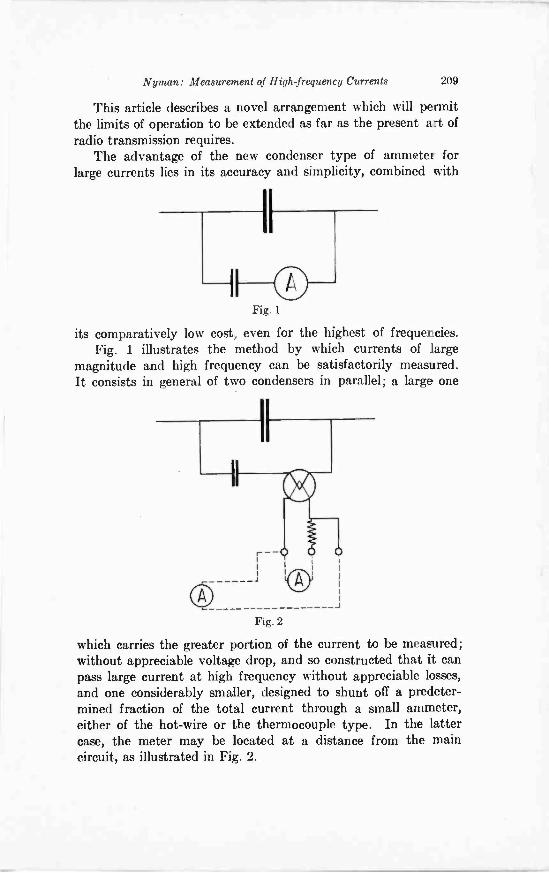
Nyman: Measurement of High -frequency Currents 209
This article describes a novel arrangement which will permitthe limits of operation to be extended as far as the present art ofradio transmission requires.
The advantage of the new condenser type of ammeter forlarge currents lies in its accuracy and simplicity, combined with
I I
Fig. 1
its comparatively low cost, even for the highest of frequencies.Fig. 1 illustrates the method by which currents of large
magnitude and high frequency can be satisfactorily measured.It consists in general of two condensers in parallel; a large one
Fig. 2
which carries the greater portion of the current to be measured;without appreciable voltage drop, and so constructed that it canpass large current at high frequency without appreciable losses,and one considerably smaller, designed to shunt off a predeter-mined fraction of the total current through a small ammeter,either of the hot-wire or the thermocouple type. In the lattercase, the meter may be located at a distance from the maincircuit, as illustrated in Fig. 2.
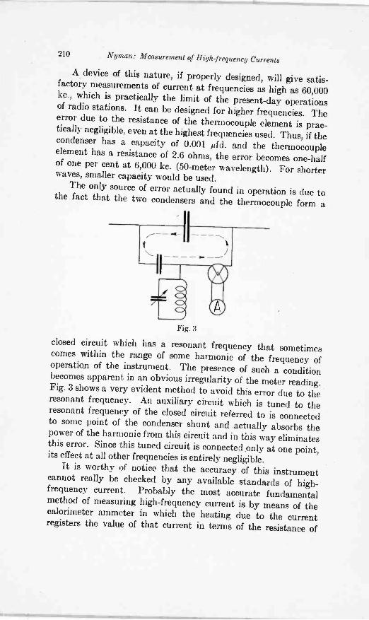
210 Nyman: Measurement of High-frequency Currents
A device of this nature, if properly designed, will give satis-factory measurements of current at frequencies as high as 60,000kc., which is practically the limit of the present-day operationsof radio stations. It can be designed for higher frequencies. Theerror due to the resistance of the thermocouple element is prac-tically negligible, even at the highest frequencies used. Thus, if thecondenser has a capacity of 0.001 Mfd. and the thermocoupleelement has a resistance of 2.6 ohms, the error becomes one-halfof one per cent at 6,000 kc. (50 -meter wavelength). For shorterwaves, smaller capacity would be used.
The only source of error actually found in operation is due tothe fact that the two condensers and the thermocouple form a
Fig. 3
closed circuit which has a resonant frequency that sometimescomes within the range of some harmonic of the frequency ofoperation of the instrument. The presence of such a conditionbecomes apparent in an obvious irregularity of the meter reading.Fig. 3 shows a very evident method to avoid this error due to theresonant frequency. An auxiliary circuit which is tuned to theresonant frequency of the closed circuit referred to is connectedto some point of the condenser shunt and actually absorbs thepower of the harmonic from this circuit and in this way eliminatesthis error. Since this tuned circuit is connected only at one point,its effect at all other frequencies is entirely negligible.
It is worthy of notice that the accuracy of this instrumentcannot really be checked by any available standards of high-frequency current. Probably the most accurate fundamentalmethod of measuring high -frequency current is by means of thecalorimeter ammeter in which the heating due to the currentregisters the value of that current in terms of the resistance of
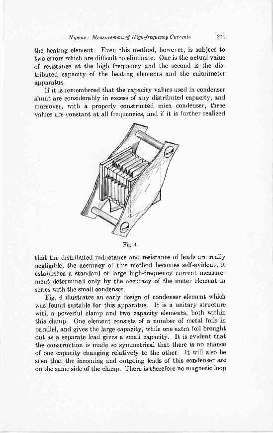
Nyman: Measurement of High -frequency Currents 211
the heating element. Even this method, however, is subject totwo errors which are difficult to eliminate. One is the actual valueof resistance at the high frequency and the second is the dis-tributed capacity of the heating elements and the calorimeterapparatus.
If it is remembered that the capacity values used in condensershunt are considerably in excess of any distributed capacity, andmoreover, with a properly constructed mica condenser, thesevalues are constant at all frequencies, and if it is further realized
Fig. 4
that the distributed inductance and resistance of leads are reallynegligible, the accuracy of this method becomes self-evident; itestablishes a standard of large high -frequency current measure-ment determined only by the accuracy of the meter element inseries with the small condenser.
Fig. 4 illustrates an early design of condenser element whichwas found suitable for this apparatus. It is a unitary structurewith a powerful clamp and two capacity elements, both withinthis clamp. One element consists of a number of metal foils inparallel, and gives the large capacity, while one extra foil broughtout as a separate lead gives a small capacity. It is evident thatthe construction is made so symmetrical that there is no chanceof one capacity changing relatively to the other. It will also beseen that the incoming and outgoing leads of this condenser areon the same side of the clamp. There is therefore no magnetic loop
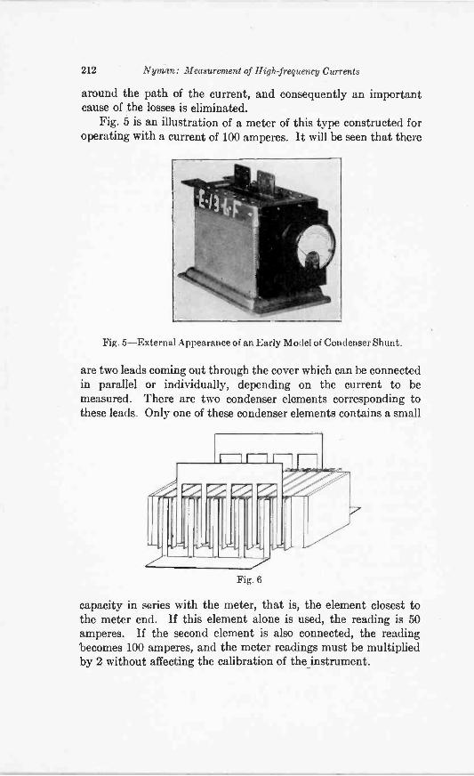
212 Nyman: Measurement of High -frequency Currents
around the path of the current, and consequently an importantcause of the losses is eliminated.
Fig. 5 is an illustration of a meter of this type constructed foroperating with a current of 100 amperes. It will be seen that there
Fig. 5-External Appearance of an Early Model of Condenser Shunt.
are two leads coming out through the cover which can be connectedin parallel or individually, depending on the current to bemeasured. There are two condenser elements corresponding tothese leads. Only one of these condenser elements contains a small
Fig. 6
capacity in series with the meter, that is, the element closest tothe meter end. If this element alone is used, the reading is 50amperes. If the second element is also connected, the readingbecomes 100 amperes, and the meter readings must be multipliedby 2 without affecting the calibration of the instrument.
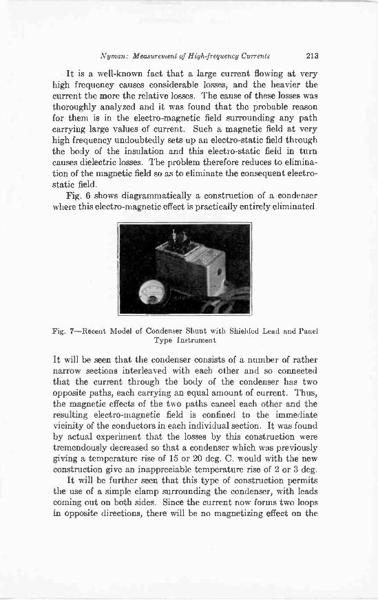
Nyman: Measurement of High -frequency Currents 218
It is a well-known fact that a large current flowing at veryhigh frequency causes considerable losses, and the heavier thecurrent the more the relative losses. The cause of these losses wasthoroughly analyzed and it was found that the probable reasonfor them is in the electro-magnetic field surrounding any pathcarrying large values of current. Such a magnetic field at veryhigh frequency undoubtedly sets up an electro-static field throughthe body of the insulation and this electro-static field in turncauses dielectric losses. The problem therefore reduces to elimina-tion of the magnetic field so as to eliminate the consequent electro-static field.
Fig. 6 shows diagrammatically a construction of a condenserwhere this electro-magnetic effect is practically entirely eliminated.
Fig. 7-Recent Model of Condenser Shunt with Shielded Lead and PanelType Instrument
It will be seen that the condenser consists of a number of rathernarrow sections interleaved with each other and so connectedthat the current through the body of the condenser has twoopposite paths, each carrying an equal amount of current. Thus,the magnetic effects of the two paths cancel each other and theresulting electro-magnetic field is confined to the immediatevicinity of the conductors in each individual section. It was foundby actual experiment that the losses by this construction weretremendously decreased so that a condenser which was previouslygiving a temperature rise of 15 or 20 deg. C. would with the newconstruction give an inappreciable temperature rise of 2 or 3 deg.
It will be further seen that this type of construction permitsthe use of a simple clamp surrounding the condenser, with leadscoming out on both sides. Since the current now forms two loopsin opposite directions, there will be no magnetizing effect on the
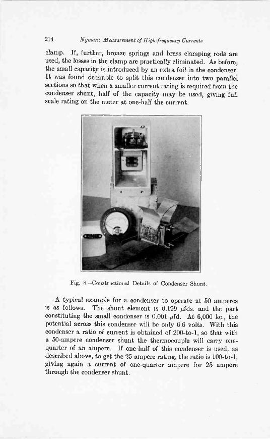
214 Nyman.: Measurement of High -frequency Currents
clamp. If, further, bronze springs and brass clamping rods areused, the losses in the clamp are practically eliminated. As before,the small capacity is introduced by an extra foil in the condenser.It was found desirable to split this condenser into two parallelsections so that when a smaller current rating is required from thecondenser shunt, half of the capacity may be used, giving fullscale rating on the meter at one-half the current.
Fig. 8-Constructional Details of Condenser Shunt.
A typical example for a condenser to operate at 50 amperesis as follows. The shunt element is 0.199 Afds. and the partconstituting the small condenser is 0.001 tifd. At 6,000 kc., thepotential across this condenser will be only 6.6 volts. With thiscondenser a ratio of current is obtained of 200 -to -1, so that witha 50 -ampere condenser shunt the thermocouple will carry one -quarter of an ampere. If one-half of this condenser is used, asdescribed above, to get the 25 -ampere rating, the ratio is 100 -to -1,giving again a current of one -quarter ampere for 25 amperethrough the condenser shunt.
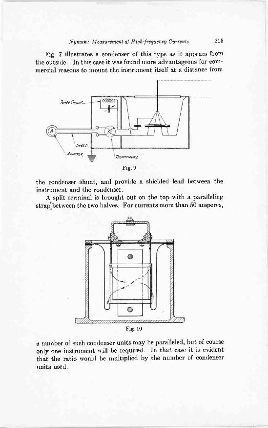
Nyman: Measurement of High -frequency Currents 215
Fig. 7 illustrates a condenser of this type as it appears fromthe outside. In this case it was found more advantageous for com-mercial reasons to mount the instrument itself at a distance from
Fig. 9
the condenser shunt, and provide a shielded lead between theinstrument and the condenser.
A split terminal is brought out on the top with a parallelingstrap:between the two halves. For currents more than 50 amperes,
Fig. 10
a number of such condenser units may be paralleled, but of courseonly one instrument will be required. In that case it is evidentthat the ratio would be multiplied by the number of condenserunits used.
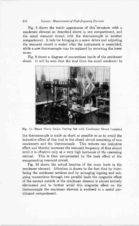
216 Nyman: Measurement of High -frequency Currents
Fig. 8 shows the inside appearance of this structurewith acondenser element as described above in one compartment, andthe small resonant circuit with the thermocouple in anothercompartment. A hole for bringing in a screw driver and adjustingthe resonant circuit is sealed after the instrument is assembled,while a new thermocouple may be replaced by removing the lowercover.
Fig. 9 shows a diagram of connections inside of the condensershunt. It will be seen that the lead from the small condenser to
Fig. 11-Short Wave Radio Testing Set with Condenser Shunt Installed
the thermocouple is made as short as possible so as to avoid theinductive effect of this lead in the closed circuit consisting of twocondensers and the thermocouple. This reduces one inductiveeffect and thereby increases the resonant frequency of that circuituntil it is effective only at a very high harmonic of the operatingcurrent. This is then compensated by the tank effect of thecompensating resonant circuit.
Fig. 10 shows the actual location of the main leads in thecondenser element. Attention is drawn to the fact that by inter-lacing the condenser sections and by arranging ingoing and out-going connections through two parallel leads the magnetic effectof the current outside of the condenser element is almost entirelyeliminated and to further avoid this magnetic effect on thethermocouple the condenser element is enclosed in a metal par-titioned compartment.
Nyman: Measurement of High frequency Currents 217
Fig. 11 illustrates the location of this instrument on a radiotransmitting set. The condenser shunt is mounted in a convenientlocation next to the ground lead, while the instrument is locatedon the instrument panel, with a shielded lead between the instru-ment and the condenser. In this particular set, which was designedfor the purpose of testing condensers, and is capable of operatingon a wide range of frequencies from 1000 meters to 20 meters, thecondenser shunt was found to give correct readings for the fullrange and for currents in excess of 50 amperes an additional parallelunit could be applied.
A meter similar to the one described above has been in continualuse for over two years on a testing set where the frequencies haveranged from 100 kc. to 6,000 kc., and the current values haveranged up to 120 amperes. It has been found that the meterindications are consistent and reliable at all these values. In fact,its accuracy has been such that it was possible to measure thevoltage in a circuit by connecting such an ammeter in series witha known condenser, and determining the voltage drop in thecondenser by calculation.
For developing a special thermocouple ammeter used inconnection with the condenser shunt, an acknowledgment is duethe Weston Electrical Instrument Corporation of Newark, NewJersey.
BOOK REVIEWS
Dielectric Phenomena: Electrical Discharge in Gases, BY S.WHITEHEAD. D. VAN NOSTRAND COMPANY, INC., New York,N. Y. 176 pages. Price $4.00.The scope of this book is outlined in the preface by E. B.
Wedmore. It is a scientific summary of what is known of electricaldischarge in gases, as the sub -title indicates. The main title is tobe justified by further publications dealing with liquids and solids.
The volume is written in three parts. The Introduction is abrief outline of the theory of ionic conduction through gases, suchtopics as "Mechanics of the Atom and Molecule," "Ionisation byImpact," "Radiations Emitted by the Discharge," and "Town-send's Continuity Theorem" being epitomized. In the secondsection the physics of electrical sparking is given, while the thirdportion of the book is concerned with corona phenomena. Theterm corona is taken as including dark, glow, and brush discharges.Mr. Whitehead's work is limited to "electrical discharges throughgases at pressures for which the mean free path is small comparedwith the electrode dimensions," thus excluding discharges in vacua,and the electric arc. An arc is understood as an electrical break-down between conductors in a gas, the electrodes themselvesbecoming sufficiently hot to contribute to the phenomena follow-ing the initial discharge.
The discussion is in the field of physics rather than engineering.The mathematical treatment of the various topics is adequatebut not prohibitively difficult. For those readers who desiregraphical results there are forty-two diagrams showing the varia-tion of gradients and other effects. An engineer who picked upthe book with the object of reading about horn gaps, the pro-portioning of the V-shaped sides, and the amount of energy whichthey may be depended on to break, would be disappointed in hissearch for specific engineering data, but he could learn how muchthe spark voltage of the sphere gap is reduced by rain or otherwater on the surfaces, and that humidity appears to have littleeffect, whereas the needle gap is markedly influenced by humidity.At the end of the book he would also find an alphabeticallyarranged bibliography covering the subject from 1860 to veryrecent publications. There is also a rather brief index.
Original Manuscript Received by the Institute, November 28, 1927.
218
Book Reviews 219
While Mr. Whitehead's résumé is hardly of interest to radioengineers generally, it should be read by transmitter designspecialists, who will find it to their advantage to substitute forisolated empiricisms a logical physical treatment of high voltagedischarges.
CARL DREHER
The Propagation of Radio Waves Along the Surface of the Earthand in the Atmosphere, BY PROFESSOR P. 0. PEDERSEN. 244pages and appendix. Published by "Danmarks naturviden-skabelige Samfund" and sold by G. E. C. Gad, Vimmelskaftet32, Copenhagen K. Denmark. Price 15 Kr. (about $4.00).In this book the author has attempted to give a connected
physical theory of radio wave propagation-and it is no doubtthe first case where really all the well-known facts of radio propaga-tion have been assembled and brought into connection with thecorresponding fields of physics.
It is first pointed out that only an ionization theory can satis-factorily explain the conditions of radio transmission, which is soextremely variable with the daytime, season, and wavelength.In the following chapters the physical basis of such a theory isworked out, and it is shown that radio experience throws lighton many problems concerning the atmosphere, the laws of ioniza-tion and recombination, etc.
In chapter IV the pressure and composition of the atmosphereare treated. It is shown that no appreciable quantities of hydrogencan be present in the higher atmosphere, which therefore consistsmerely of helium-together with small percentages of nitrogenand oxygen; and that radio experience 'determines quite preciselythe air pressure between 80 and 160 km. altitude. This determina-tion would probably be in good agreement with the mass -densityresulting from Lindemann and Dobson's investigations of meteors,if some errors in their theory are corrected.
Chapter V deals with the ionization of the atmosphere. Thecoefficient of recombination is shown to be proportional to theair pressure according to the theory of Langevin but for verylow pressures will approach a constant value of about 10-6 timesthat at 760 mm Hg pressure, as shown in a theorem of the author.The different possible sources of ionization are now investigated.The ultra -violet radiation from the sun is the chief determining
Original Manuscript Received by the Institute, December 22, 1927.
220 Book Reriews
factor though radiation from stars of very high temperature alsohas some influence on the propagation of very long waves.Formulas are developed for the numbers of free electrons and ofmono -molecular and complex ions per cc. by day and by night.
In chapterd VI and VII is determined the influence of electronsand ions on the dielectric constant and the conductivity of theatmosphere with or without the magnetic field of the earth acting,and taking into consideration the collisions between the differentcharged and uncharged particles. The reader will find severalnew and exact formulas set forth in this part of the book. Inchapter VIII the dependency of the refractive index and theattenuation constant on the dielectric constant and the con-ductivity are treated. The approximate formula n = Ve is shownto be very unsatisfactory in many cases, and the exact formulas,taking into consideration the influence of both the dielectricconstant and the conductivity, are given and represented in curvesand charts.
For any set of values of the refractive index and the attenuationconstant expressed as functions of the height over the earth andof the frequency we may determine the path and the attenuationof rays leaving the earth under a given earth angle according tothe methods developed in chapter X. It is pointed out that theray path will depend on both the earth angle and the frequency.This section of the book gives a very striking description of whathappens to a ray penetrating into an ionized part of the atmos-phere and indicates the average picture of radio propagationresulting from any ionization theory.-In other different theoremsthe influence of the refractive index and the attenuation constanton the rotation of the plane of polarization, on the phase- andgroup -velocity, etc., is treated.
In chapters IX and XI, the fundamental theories developedin the foregoing chapters are used for determining the actualstate of ionization and for checking the theory against experience.Here are also used the old simplified theories of propagation listedin chapters I -III and the very useful formulas for reflection atthe surface of the earth developed in chapter VIII. The ionizationis shown to have its maximum value of about 103 electrons per cc.at an altitude of about 130 km. by day and 2 X10⁵ electrons percc. at 155 km. at night, and to have its lower boundary at analtitude of 90-100 km. (mean values for summer) This ionizationcan just be produced by the energy of the ultra -violet in sunlight,

Book Reviews 221
and the total conductivity due to this ionization will probablyagree fairly well with the value determined from the daily varia-tions of terrestrial magnetism, if Chapman's theory of this phe-nomenon is altered so as to take into consideration the muchgreater conductivity of the air in the direction of the magneticfield than perpendicular to it.
On the other hand, starting from this state of ionization allthe well-known facts of radio wave propagation may be explained,at least qualitatively and in many cases even quantitatively.The outlines of the process of radio propagation are in generalabout as follows:
Long waves will be refracted without severe losses from a heightof about 90-100 km. even for great earth angles. Both electronsand ions are effective in bending the rays. The direct earth waveis also of importance for distances up to about 1,000 km. and(during summer days) gives the interference pattern found byHollingworth. At greater distance the refracted waves will pre-dominate; still, the attenuation will not be so great as that foundby Zenneck for propagation parallel to the earth because themultiple refleadons will distribute the energy almost uniformlyover the space between the earth and the ionized "layer," whileaccording to Zenneck the energy is propagated along the boundarysurfaces and is nearly zero somewhere between them. The totalenergy is therefore actually much greater than that found byZenneck, while the losses in the earth and in the ionized air arealmost the same. Taking this into consideration, the author findsan attenuation for long waves which is in rather good agreementwith the practical data as contained in Austin-Cohen's formula.
During summer days, the long waves will be refracted from arather low height where the air pressure is so high and the numberof heavy ions relatively so great that the magnetic field of theearth will have very little influence; the conditions of transmissionwill therefore be good and steady. During winter days, and duringnight time, the heights of refraction will be greater so that themagnetic field will be capable of rotating the plane of polarizationand giving double refraction, and therefore will cause extremelyvariable conditions and poor (inaccurate) direction finding. Thisfact supplies a very good means for determining height of re-fraction of the very long waves.
For very short wavelengths the ground waves will be absorbedat very small distances from the transmitter. The rays will be
222 Book Reviews
refracted at heights from 130 to 150 km. and by electrons only.Rays of wavelengths shorter than a certain limiting value cannotbe refracted back to the earth; these limiting values are assumedto be 8.5 m. by day and 18.9 m. by night. These data determinethe maximum numbers of electrons per cc. by day and by nightand also a maximum value of the recombination constant at theseheights. When the wavelength increases from these limitingvalues, the electrons will be able to refract a greater part of theradiated energy but at the same time they will give greater losses.For waves having a great part of their paths in or near to theheight of maximum electron density there will therefore be amaximum of range for wavelengths of about 15-22 m. Thesewaves are able to encircle the earth, propagated mostly at a heightwhere their radius of curvature is nearly equal to the radius ofthe earth. When phase- and group -velocities are not confounded,the measurements of the time required by the signals to encirclethe earth give average heights of transmission of the right orderof magnitude, viz., about 150 km. The fact that it is just possiblefor a ray of 15 to 22 m. wavelength to be transmitted around theearth gives us rather good values of the number of collisionssuffered by an electron per second in these heights and thereforealso of the air pressure and assures us that no appreciable amountsof hydrogen can be present there.
Short waves of wavelengths greater than about 22 m. will berefracted from heights of 110 to 140 km. They are best transmittedduring night time while the very short waves can only be bentdown during day time, when the ionization is maximum. The"skip" phenomena are simply deduced from the shape of the curvesof the refraction index and the fact that there is no ground waveexcept very near to the transmitter.
For waves of medium wavelength the refracted rays will bemore attenuated than those of short wavelength and the groundwave will suffer a greater loss than that of a long wave. Thereforethe day and night ranges will have minima for wavelengths ofabout 200 m. The magnetic field of the earth makes the dropeven more pronounced, even if there is no real resonance effectbecause of the collisions between electrons and molecules andbecause of the influence of the heavy ions.
Those readers who are primarily interested in the practicalresults will find it most convenient to skip over the mathematicalderivations in the first part of the book. They are advised to
Book Reviews 223
start with chapter XI where the author's chief ideas of radiotransmission are set forth and to go back to the earlier chaptersonly now and then for reference.
The book contains a comprehensive set of references to theliterature of this field which is of great value in view of the hugenumber of papers presented on these subjects-in fact, it is hardlyfeasible to read even the more important of them.
And this bibliography in connection with the profound criti-cism and the valuable new ideas given in the book-which mayreally be said to supply us with the missing link between radioexperiments and the corresponding fields of physics-stronglysupports the hope expressed by the author that it will serve asa basis for the future development both of the physics of thehigher atmosphere and of the theory of radio wave propagation.
J. C. F. RYBNER
New York
New JerseyCanada
CaliforniaNew YorkHolland
California
GEOGRAPHICAL LOCATION OF MEMBERS ELECTEDJanuary 4, 1928
Transferred to the Fellow gradeNew York City, 434 E. 141st St. Fried, J. D.
Transferred to the Member gradeMaplewood, 5 Park Ave Cunningham, F. W.Toronto, 62 Pleasant Blvd. Patience, A. M.
Elected to the Member gradeSan Francisco, 611 Crocker Bldg. Lippincott, D. K.Brooklyn, 70 Washington St. Siegil, SamuelThe Hague, Van Swietenstraat 16 Schotel, Gerrit
Elected to the Associate gradeGlendale, 1246 Elm Avenue Minkler, L. D.Los Angeles, 703 W. 81st St Dalton, S. P.Sacramento, P. 0. Box 632 Barlow, Wm.San Bernardino, 831 Fifth St. Beeson, K. H.San Diego, 1332 Bush Street Clement, J. D.San Diego, 4657 Oregon St Partch, Paul C.San Francisco, 812 Hobart Bldg Tuel, A. Y.San Francisco, 719 Scott St. Patron, A. E.
Connecticut Bridgeport, 200 Hazelwood Ave. Mapes, H. T.Waterbury, 9 Burton St Greenblatt, Louis
Dist. of Columbia Washington. Radio Bldg. Hall, E. F.Florida St. Petersburg, 1127 -12th St. Wittstruck, H. H.Illinois Bloomington, 511 N. Mason St. Goodfellow, E. D.
Chicago, 349 East 59th St. Cook, B. L.Chicago ,2600 Indiana Ave Mae Dermain L. DChicago, 49121 Jackson Blvd Ewald, F. J., Jr.Chicago, 2011 Jarvis Ave. Barlow, Wm. H.
Chicago, 940 West 55th $tJohn, K. B.Noonan, J. J
Chicago, 1815 Morse Ave
Indiana Bloomington, 1000 South Lincoln St Hazel, H. C.Kansas Topeka, 230 Woodlawn Ave Jones, G. I.Louisiana New Orleans, 220 So. Johnson St. Collins, J. F.Maryland Baltimore, 530 Richwood Ave Houston, G. P.Massachusetts Boston, 191 Friend St . Krikorian, D. K.
East Springfield, 94 Edendale St Kinsman, W. D.Malden, 21 Garland Ave Winchell, W. H.
Michigan Detroit, 2914 Book -Cadillac Hotel Harper, J. K.Detroit, 3026 Lotbrop Ave Byerlay, H. L.Detroit, 8037 Medbury Ave. Friedenthal, A.Detroit, 2170 St. Clair Ave Ballbach, N. C.
Nebraska Omaha, 2230 Jones St Cramer, W. R.New Jersey East Orange, 402 N. Grove St. Beidleman, H. B.
Ft. Monmouth, 15th Signal Ser. Co Wilson, L. E.Glen Ridge, 30 Edgewood Road Cunliffe, P. R.Ridgefield Park, 205 Preston St. Pearee, ArthurWest Orange, 7 Helen Avenue Tucker, M. E.
New York Albany, 241 Quail St Ainsworth, R. I.Bronx, 494 Concord Ave Zysman, HarryBrooklyn, 485 East 21st St. Tucker, R. A.Brooklyn, 755 Gravesend Ave Kennedy, H. E.Brooklyn, 85 Montrose Ave. C01:180li, VincentBuffalo, 555 East Amherst St. Stevens, H. A.L. I., Elmhurst, 3714 -92nd St. Banks, A. C.L. I., Jamaica, 150 -08 -116th Drive Albert, M. M.New York City, 2022-233 Broadway Fisk, Wm. G.
Pleasanton, A. W.New York City, 463 West St Delimel, R. C.New York City, 771 East 180th St
New York City, 463 West St. Freeman, R. H.New York City, 254 West 98th St. Kanely, N. J.Orient Vail, L. G.Schenectady, 1719 Broadway Billins, J. H.Schenectady, 501 Campbell Ave Hoard, N. F.Schenectady, 318 Clinton St. Selby, E. 0.Schenectady, 143 Division St Dodge, A. 0.Schenectady, 37 Eleanor St. Stone, F. B.Schenectady, 806 Grant Ave Hoffer, G. M.Schenectady, 9 Park Place Priebe, FrankSchenectady, 606 Pleasant St Nickle, E. G.Schenectady, 205 Seward Place Frank, C. W.
224
Geographical Location of Members Elected January 4, 1928 225
Schenectady, 231 Seward Place Newbold, W. H.Schenectady, 929 State St. Demmer, A. H.Schenectady, 962 State St Payne, J. H.Schenectady, 1452 State St. Matthews, A. C., Jr.Schenectady, 1426 Sumner Ave Cottrell, M.Schenectady, 13 Swan St. Schwartz, H. F.Schenectady, 8 Union St Serrell, RobertSchenectady, 900 Union St Witty, W. M.Schenectady, 1008 Union St Hitt, A. B.Schenectady, 802 Webster St. Wallace, M. J.Scotia, 104 Collins St. Gardiner, P. C.Scotia, 104 Collins St Romander, HugoScotia 6 North Toll St Zuchter, PieterScotia, 12 Riverside Ave Norton, C. T.Wayland, 112 South Main St McCoy, J. C.
Ohio Cleveland, 1130 B. of L. E. Bk. Bldg Schlesinger, B. R.Cleveland 19400 Shoreland Ave Hannum, J. C.Columbus, 1940 Stanford Road Stocker, A. C.Columbus, 117 West Frambes Ave Shuler, J. H.Dayton, 216 Hartford St Bourne, G. E.Mansfield, North Main Road Kissel, M. M.
Oklahoma Oklahoma City, 300 Grain Ex. Bldg Mier, C. W.Oklahoma City, 927 West 10th St Hirdler, F. C.
Pennsylvania Allenwood Schooley, HaroldAvalon, 123 Harrison Ave Allen, J. G.Bethlehem, 39 East Wall St Davis, N. H.East Pittsburgh, Westinghouse Co Hitchcock, R. D.Essington, P. O. Box No. 66. Geise, J. C., Jr.Philadelphia, 2445 East Huntingdon St. Robinson, A. V.Philadelphia, 3650 N. 7th St Klenk, G. J.Philadelphia, Somerton Dunn J. C.Pottstown, 447 Chestnut St. Fisher, C. H., Jr.Wilkinsburg, 2083 Chalfont St. Amick, Wm. M.Wilkinsburg, 601 Ecker Way Bohle, Wm. H.
South Dakota Yankton, 907 W. Fourth St. Mead, G. H.Texas Houston, 2407 Keene St Gower, S. G.
Houston, 1843 Kipling Ave. Croesland, H. A.Houston, 1211 Milam St. McFarland, N. R.
Utah Salt Lake City. 125 West Fifth South Bird, C. R.Virginia Richmond, 914 West Broad St. Wood, W H.Canada Ontario, Ridgeway Mann, G. F.
Ont., Toronto 3 34 Coomine Rd Ford, J. S.Quebec, Grand Mere, 193 Laurentide Purnell, C. F.
England London, S. W 18 19 Earlsfield Rd Stanesby H.London, Herse Hill. S. E. 24 Winterbrook Rd 0del L. F.Portsmouth, Hants, Southsea, 48 Lowcay Rd Kenedy. J. C.
Germany Leipzig, Dreadner Bank Wilder, M. P.Holland Hilversum, Neuweg 259 Brenner, 8. W.Japan Tokyo, Marunouchi, Wireless Dept. N. Y. K. Owada, Mankitsu
Tokyo, 1500 Shimo-Shibuya Hashimoto, Chu iiPhil. Islands Manila, c/o Manila Electric Co African, TiburcieStrait S. Singapore Collyer Quay Bank Chambers Purdy, Leslie
Elected to the Junior gradeCalifornia Long Beach, 346 Molino Ave Hancock, J. W., Jr.Connecticut Bridgeport, 91 Columbia St Cho sky, P. A.
East Hampton, P. 0. Box 115 Carini, LouisMassachusetts Somerville, 21 Windsor Road Grant, L. E.Minnesota Minneapolis, 1227 -4th St. S. E Arthur, G. B., Jr.New York Brooklyn, 99 Snediker Ave. Laford, Herbert
New York City, 157 East 89th St Wald, A. H.New York City, 771 East 180th St Pleasanton, D. W.
Ohio Marion, 639 Pearl St. Homier, D. E.Pennsylvania Milton, 201 N. Front St Butler, W. M.
Pottstown. 25 King St. Mellon, R. E.Canada Ont. N. Hamilton 15 Huxley Ave. Bailey, A. L.

...

To no other industry does this ad-vice of Davy Crockett's apply withgreater force than to Radio.
It is because they must be surethey are right that designing andproduction engineers of the fore-most manufacturers consult withPolymet's engineers. This co-operation has been the means ofsolving the particular and indivi-dual condenser and resistance prob-lems of these manufacturers.
Through this combination of en-
gineering experience Polymet meetsthe specific requirements of the in-dividual manufacturer with con-densers and resistors of accuracyand dependability, thus assuring theperfect performance of the manu-facturer's unit.
You are now carrying on yourexperiments in anticipation of thecoming season. Let us help you.Our entire staff is at your service.What we are doing for other manu-facturers we can also do for you.
POLYMET MANUFACTURING CORPORATION591 Broadway, New York
To Dealers and JobbersPolymet is one of thebest known and mostspecified lines of radioessentials. You shouldstock Polymet parts tomeet the popular demand.Write for catalog of complete line and full par-ticulars.
Polymet Wire WoundResistors
Polymet Wire Wound Re-sistors are high wattagetype resistances designedfor heavy work. Theyare equipped with specialmounting lugs that savetime in assembly. Builtin all popular sizes andto your specifications.
POLYMET CONDENSERSWhen writing to advertisers mention of the Proceedings will be mutually helpful.
TX
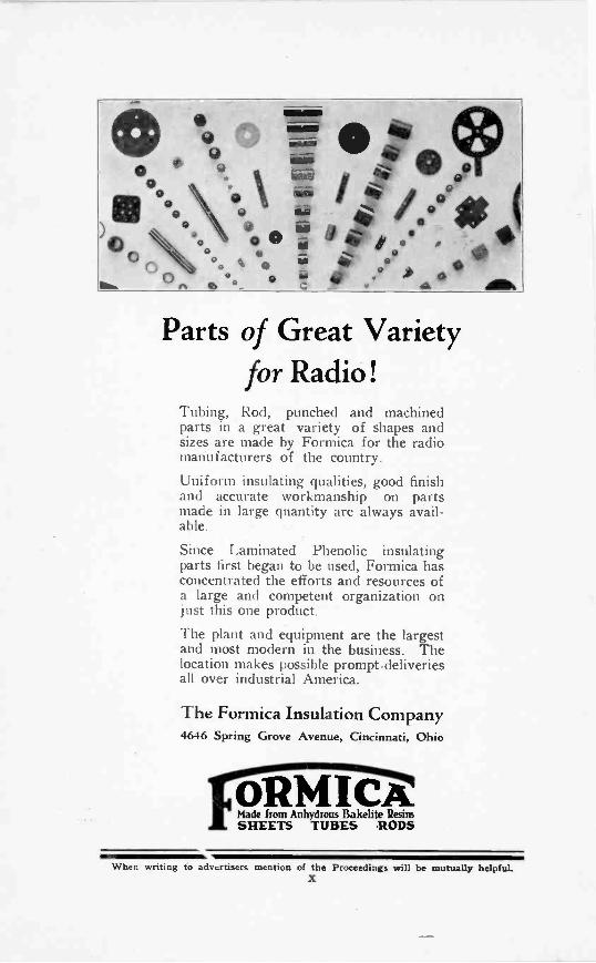
Parts of Great Varietyfor Radio!
Tubing, Rod, punched and machinedparts in a great variety of shapes andsizes are made by Formica for the radiomanufacturers of the country.
Uniform insulating qualities, good finishand accurate workmanship on partsmade in large quantity are always avail-able.
Since Laminated Phenolic insulatingparts first began to be used, Formica hasconcentrated the efforts and resources ofa large and competent organization onjust this one product.
The plant and equipment are the largestand most modern in the business. Thelocation makes possible prompt.deliveriesall over industrial America.
The Formica Insulation Company4646 Spring Grove Avenue, Cincinnati, Ohio
ORM ICA_Made horn Anhydrous Bakelite ResinsSHEETS TUBES RODS
When writing to advertisers mention of the Proceedings will be mutually helpfuLX
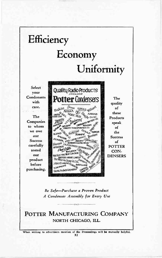
Efficiency
Economy
Uniformity
Selectyour
Condenserswithcare.
TheCompaniesto whomwe owe
ourSuccess
carefullytestedour
productbef ore
purchasing.
Quality Radio ProductsMCI-UOM
Potter Condensers
13aPeAmErAB3/44 -51106aloonEk
4-ttst
Gore G..701FL(
Nip-04 wo600°.,dAR ER Oa
K1NE CO0 MO24(NIV-`44,4111/0atO
eqt004. at.01414,-c*EER.Inalti`w5mmStaPu COLV
MOD WOW 1:
ITBISLOE liiCeNEIVAtoRIZEINn.49:116pacLAREN
axr C11411°L 1/4
nieC AlIZEauta...4;:"""5WIMPta,euumme *V
ECVCP"°146 ifBeilnalOeliCt Coop
Thequality
ofthese
Productsspeak
ofthe
Successof
POTTERCON-
DENSERS
Be Safe-Purchase a Proven ProductA Condenser Assembly for Every Use
POTTER MANUFACTURING COMPANYNORTH CHICAGO, ILL.
When writing to advertisers mention of the Proceedings will be mutually helpfuLXI
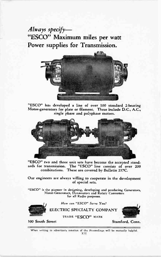
Always specify-"ESCO" Maximum miles per wattPower supplies for Transmission.
"ESCO" has developed a line of over 100 standard 2 -bearingMotor -generators for plate or filament. These include D.C., A.C.,
single phase and polyphase motors.
"ESCO" two and three unit sets have become the accepted stand-ards for transmission. The "ESCO" line consists of over 200
combinations. These are covered by Bulletin 237C.
Our engineers are always willing to cooperate in the developmentof special sets.
"ESCO" is the pioneer in designing, developing and producing Generators,Motor -Generators, Dynamotors and Rotary Converters
for all Radio purposes.
1110How can "ESCO" Serve You?
ELECTRIC SPECIALTY COMPANY
TRADE "ESCO" MARE o300 South Street Stamford, Conn.
When writing to advertisers mention of the Proceedings will be mutually helpful.Xi 1
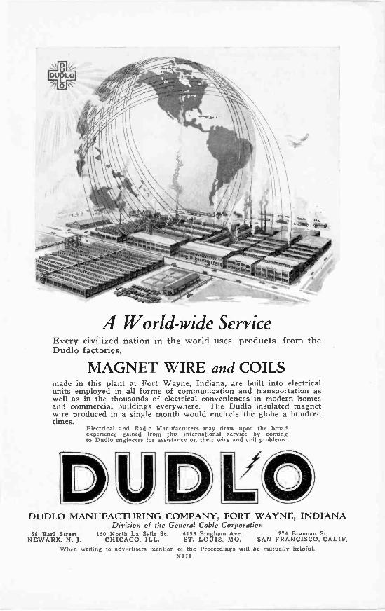
A World-wide ServiceEvery civilized nation in the world uses products from theDudlo factories.
MAGNET WIRE and COILSmade in this plant at Fort Wayne, Indiana, are built into electricalunits employed in all forms of communication and transportat-on aswell as in the thousands of electrical conveniences in modern homesand commercial buildings everywhere. The Dudlo insulated magnetwire produced in a single month would encircle the globe a hundredtimes.
Electrical and Radio Manufacturers may draw upon the broadexperience gained from this international service by comingto Dudlo engineers for assistance on their wire and coil problems.
DUDLO MANUFACTURING COMPANY, FORT WAYNE, INDIANADivision of the General Cable Corporation
56 Earl Street 160 North La Salle St. 4153 Bingham Ave, 274 Brannan St.NEWARK, N. J. CHICAGO, ILL. ST. LOUIS, MO. SAN FRANCISCO, CALIF.
When writing to advertisers mention of the Proceedings will be mutually helpfuLXIII
PROFESSIONAL ENGINEERING DIRECTORYFor Consultants in Radio and Allied Engineering Fields
The J. G. WhiteEngineering Corporation
Engineers-ConstructorsBuilders of New York Radio
CentralIndustrial, Steam Power, and GasPlants, Steam and Electric Rail-
roads, Transmission Systems.43 Exchange Place New York
Q R VRADIO SERVICE, Inc.
JOHN S. DUNHAMJ. F. B. MEACHAM
Devoted to Servicing BroadcastReceivers Exclusively
1400 BROADWAY, NEW YORK
WISCONSIN 9780
Need Trained Radio Men?Our Employment Department can sup-ply thoroughly trained, experiencedRadio Mechanics, Salesmen, Assemblers,Repairmen, Operators, etc.No charge to employer or employee. Ifyou need expert Radio help, let usrecommend some one from our list.Bulletin of available men sent uponrequest.
National Radio InstituteDept. I.R.E., Washington, D. C.
BRUNSON S. McCUTCHEN
Consulting Radio Engineer17 State Street
NEW YORK
Electrical TestingLaboratories
RADIO DEPARTMENTalso
Electrical, Photometric,Chemical and Mechanical
Laboratories80th Street and East End Ave.
NEW YORK, N. Y.
J. E. JENKINS and S. E. ADAIREngineers
Broadcasting EquipmentGeneral Radio Telephone
Engineering
1500 N. DEARBORN PARKWAYCHICAGO, ILLINOIS
RADIO ENGINEERWANTED
For Receiver design and labora-tory work by an establishedCanadian Manufacturer. Supplyfull particulars of experience,age, salary, etc., to Box 222-I.R.E. Proceedings.
John Minton I. G. Maloff
JOHN MINTON, Ph.D.Consulting Engineer
forDeveloping - Designing -
Manufacturingof
Radio Receivers, Amplifiers, Transform-ers, Rectifiers, Sound Recording and
Reproducing Apparatus.Radio and Electro-Acoustical
Laboratory8 Church St. White Plains, N. Y.
When writing to advertisers mention of he Proceedings will be mutually helpfuLXIV
Condenser Specialists
"B" Eliminator Unitsfor AC and All -Electric Sets
Supplying the needs of setmanufacturers is our specialty.Right now the trend is towardcomplete built-in power units inA -C operated sets. Let usshow you how happily we cansolve the condenser problem foryour eliminator units as wellas your other condenser needs.
WE make one thing and one thing only-wax im-pregnated paper condensers in medium and large
capacities. We make no set hardware, no eliminators,no transformers, no parts, no sets. Our entire concen-trated effort is on one product alone. Such specializationassures highest quality, economical production and realservice.
Millions of Fast Condensers are in daily use in rash()sets made by the leading set manufacturers. Fast con-densers are renowned for their high insulation resistanceand excellent and dependable electrical characteristics.
Manufacturers looking for a dependable source ofsupply will find here one of the largest organizations ofits kind in the world.
Send us your specifications.
e3982 Barry AvenueDept. I.R.E.
Chicago, U. S. A.Established 1919
When writing to advertisers mention of the Proceecings will be mutually helpful.
XV
Crescent Laviteis the pioneer resistance andstill in the van. Economical insize but gluttons for punish-ment.
Used by U. S. Government,General Electric Co., BellTelephone Laboratories,West-inghouse Electric and Manu-facturing Co., and ninetybroadcast stations.
Write for data which will besupplied on request.
Cresradio Corporation166-32 Jamaica Ave., Jamaica, N. Y.
When writing to advertisers mention of the Proceedings will be mutually helpfuLXVI
for that A -C Tube Job!
NEW PROBLEMS have appeared withA -C tubes. One is volume control. An-
other is filament and heater control. Stillanother is hum. And still another is tone con-trol.
Ready solutions have been found in the ap-plication of proper resistance values-not mereapproximations, but precise, micrometric, re-liable resistance, instantly adjustable to any de-sired value and then held at that value for anindefinite period.
Once more the Clarostat has provided thenecessary micrometric resistance. Thus thesimplest solution of the A -C receiver volumecontrol, is the Volume Control Clarostat placedacross antenna and ground terminals. A -Ctubes can be provided with proper heating cur-rent, despite line -voltage fluctuations, by meansof a Power Clarostat in the input circuit ofthe transformer. A -C hum disappears throughproper operating voltages in heating, plate andgrid circuits, by means of Power and StandardClarostats. Tone control, from the sharp, crispwords of the distant orator, to the soft, mel-low, soothing slumber hour music, is obtainedwith the Volume Control Clarostat alone or incombination with a fixed condenser.
Four types of Clarostats, in four wattage rat-ings and any resistance ranges, will solve yourA -C and socket power problems. And we canshow you how, if you so desire.
Consult with us regarding your resistanceproblems. We shall be glad to co-operatein working out a solution. And when youspecify Clarostats, be sure you get genuineClarostats stamped with the name on the
metal shell!
VOLUME CONTROL CLAROSTAT(Illustrated)
For volume and tone control,as well as plate and gridvoltage adjustments. 7 -wattrating.
STANDARD CLAROSTATFor plate and grid voltageadjustments, particularly forgroup of tubes. 20 -watt rat-ing.
HEAVY-DUTY CLAROSTATFor control of line -voltageconditions in moderate capac-ity socket -power unit, and forother heavy-duty applications.25 -watt rating.
POWER CLAROSTAT(Illustrated)
For line -voltage control inelectrified receivers andpower units, and reduction ofhigh voltage to 90 volts andless in largest power am-plifiers. 40 -watt rating.
American Mechanical Laboratories, Inc.NIg..A1311.11.
R IN A Specialists in Variable Resistors
285 N. Sixth St. :: Brooklyn, N. Y.
cLAROST /A TWhen writing to advertisers mention of the Proceedings will be mutually helpful.
XVII

WESTONAnnounces
A NEW
triple -range
voltmeter
150/ 8 / 4 / volts
For Testing A. C. Supplyand A. C. Tube Voltages
A new design of the Weston Model 528 A. C. Portablevoltmeter, having three ranges to meet the require-ments of A. C. receiver testing, is now available.This new instrument has been eagerly awaited by theradio fraternity-manufacturers, laboratories, dealers,service men and set owners-all of whom have needfor a small, compact and high grade A. C. meter forgeneral testing work.The electrical characteristics of this model are excep-tional for instruments of this size. They are respon-sive and excellently damped, may be used continu-ously at full scale reading, and are accurate on anycommercial frequency.The Voltmeters are also made in double ranges up to 600volts, with self-contained resistances of an exceptionally highvalue. Single range Ammeters, from 1 to 30 amps., are fur-nished in this same design. Write for the new Weston RadioBooklet as well as the new General Catalog-an indispens-able reference for users of scientific instruments.
WESTON ELECTRICAL INSTRUMENT CORPORATION73 Frelinghuysen Ave. Newark, N. J.
WESTONRADIO
I NSTRUMENTSWhen writing to advertisers mention of the Proceedings will be mutually helpful.
XVIII
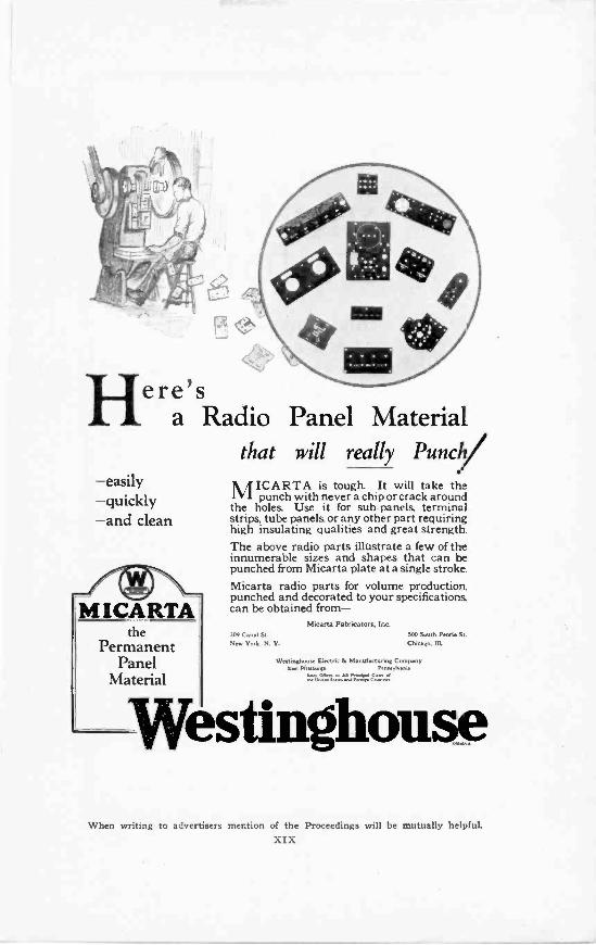
Here'sa Radio Panel Material
that will really Punch/-easily- quickly-and clean
/4 .4M I CARTA-1
thePermanent
PanelMaterial
M'CARTA is tough. It will take thepunch with never a chip or crack around
the holes. Use it for sub -panels, terminalstrips, tube panels, or any other part requiringhigh insulating qualities and great strength.The above radio parts illustrate a few of theinnumerable sizes and shapes that can bepunched from Micarta plate at a single stroke.Micarta radio parts for volume production,punched and decorated to your specifications,can be obtained from-
Micarta Fabricators, Inc.309 Canal St.Neu' York. N. Y.
MO South Peoria StChicago. Ill.
Westinghouse Electric h Manufacturing CompanySan Postman Penne Omens
It7:771N:eter;=.
WestinghouseWhen writing to advertisers mention of the Proceedings will be mutually helpful
XIX
An invaluable book forWireless Experimentersand Radio Engineers!
POSTFREE
21'9
WIRELESS
DIRECTIONFINDING
and
DIRECTIONAL RECEPTIONBy R. Keen, B.Eng. (Hons.)
Second Edition: Revised and Enlarged
THIS volume, written by an expert upon his sub-ject, deals with the principles of Direction and Posi-tion Finding in such a way that the subject may begrasped easily by engineers tackling this field ofwireless work for the first time. The entire matterhas been carefully revised and in part rewritten, andfurther information, obtained subsequent to the firstedition, has been incorporated. Numerous photo-graphs and diagrams are included, together with someinformation concerning aircraft installations.
LIST OF CONTENTS.DIRECTIONAL PROPERTIES OF AERIALSYSTEMS : FRAME AERIAL RECEPTION:ROTATING FRAME D.F. INSTALLATIONS:THE BELLINI-TOSI SYSTEM: MAPS: POSI-TION FINDING AND WIRELESS NAVIGA-TION: BEACON TRANSMITTERS: NIGHTEFFECT AND OTHER FREAK PHENOMENA:THE SHORE D.F. INSTALLATION : THE SHIPD.F. INSTALLATION: THE AIRCRAFT D.F.INSTALLATION: FAULT CLEARING ANDMAINTENANCE: NOTES ON FIELD ANDNAUTICAL ASTRONOMY: BIBLIOGRAPHY:INDEX.
Please send money order for 21/9 to cover the costof the book and postage. The postal authorities willinform you as to the amount required in U.S.A. cur-rency. Orders (with remittance) should be addressedto:
ILIFFE & SONS LIMITEDDorset House, Tudor St., London, E.C. 4, England
When writing to advertisers mention of the Proceedings will be mutually helpfuLXX
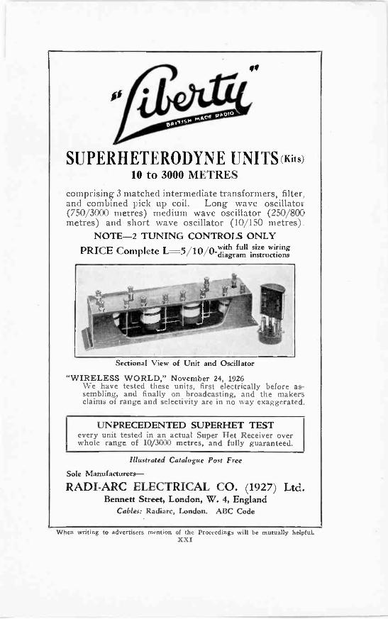
cc
SUPERHETERODYNE UNITS:Kits)10 to 3000 METRES
comprising 3 matched intermediate transformers, filter,and combined pick up coil. Long wave oscillator(750/3000 metres) medium wave oscillator (250/800metres) and short wave oscillator (10/150 metres).
NOTE -2 TUNING CONTROLS ONLYPRICE Complete L=5/10 i0_1dviiathgrafumll isniszteruwaiirowngs
Sectional View of Unit and Oscillator
"WIRELESS WORLD," November 24, 1926We have tested these units, first electrically before as-sembling, and finally on broadcasting, and the makersclaims of range and selectivity are in no way exaggeratec.
UNPRECEDENTED SUPERHET TESTevery unit tested in an actual Super Het Receiver overwhole range of 10/3000 metres, and fully guaranteed.
Illustrated Catalogue Post Free
Sole Manufacturers-
RADI-ARC ELECTRICAL CO. (1927) Ltd.Bennett Street, London, W. 4, England
Cables: Radiarc, London. ABC Code
When writing to advertisers mention of the Proceedings will be mutually helpfuLXXI
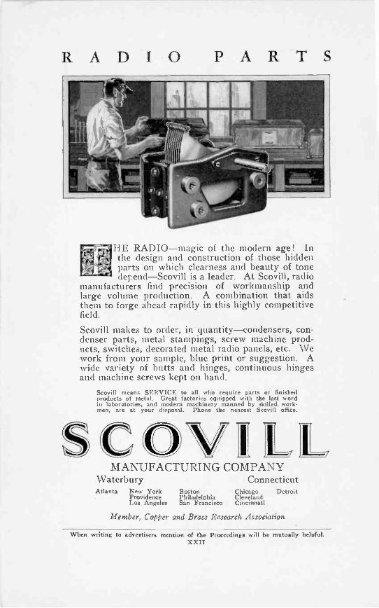
Waterbury
RADIO PARTS
HE RADIO-magic of the modern age! Inthe design and construction of those hiddenparts on which clearness and beauty of tonedepend-Scovill is a leader. At Scovill, radio
manufacturers find precision of workmanship andlarge volume production. A combination that aidsthem to forge ahead rapidly in this highly competitivefield.
Scovill makes to order, in quantity-condensers, con-denser parts, metal stampings, screw machine prod-ucts, switches, decorated metal radio panels, etc. Wework from your sample, blue print or suggestion. Awide variety of butts and hinges, continuous hingesand machine screws kept on hand.
Scovill means SERVICE to all who require parts or finishedproducts of metal. Great factories equipped with the last wordin laboratories, and modern machinery manned by skilled work-men, are at your disposal. Phone the nearest Scovill office.
7 7
MANUFACTURING COMPANYConnecticut
Atlanta New York Boston Chicago DetroitProvidence Philadelphia ClevelandLos Angeles San Francisco Cincinnati
Member, Copper and Brass Research Association
When writing to advertisers mention of the Proceedings will be mutually helpful.XXII
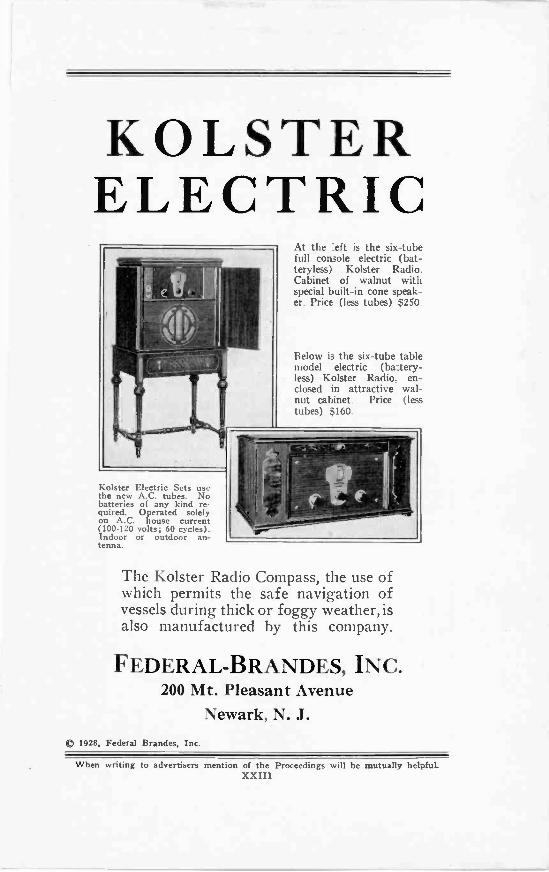
KOLSTERELECTRIC
At the :eft is the six -tubefull console electric (bat-teryless) Kolster Radio.Cabinet of walnut withspecial built-in cone speak-er. Price (less tubes) $250.
Below is the six -tube tablemodel electric (ba:tery-less) Kolster Radio, en-closed in attractive wal-nut cabinet. Price (lesstubes) $160.
Kolster Electric Sets usethe new A.C. tubes. Nobatteries of any kind re-quired. Operated solelyon A.C. house current(100-120 volts; 60 cycles).Indoor or outdoor antenna.
The Kolster Radio Compass, the use ofwhich permits the safe navigation ofvessels during thick or foggy weather,isalso manufactured by this company.
FEDERAL-BRANDES, INC.200 Mt. Pleasant Avenue
Newark, N. J.C) 1928, Federal Brandes, Inc.
When writing to advertisers mention of the Proceedings will be mutually helpful.XXIII
iilliqPiP1411
An AnnouncementIntroducing a Line of Filterand By -Pass Condensers ofUnimpeachable Quality
FOR thirty five years, Automatic Electric Inc., one ofthe largest manufacturers of communication equipmentin the world, has been producing fixed condensers to
meet the rigid specifications of large telephone companies.Thousands of these condensers, installed twenty or moreyears ago in connection with telephone exchange equipmentwhere they are subjected continually to high voltages, are
" still giving satisfactory iervice.
The long life of the condensers produced by AutomaticElectric Inc. is due to special and exclusive processes of fab.rication which render them particularly fitted for the highvoltages and other conditions peculiar to radio power devices.
To meet the growing demands of the radio business for bet.tcr filter and bypass condensers, arrangements have beenmade with Automatic Electric Inc. to supply condensers ofthe finest quality, both as to material and construction, to theradio trade and to manufacturers of radio apparatus. Thecompany's condenser department has been enlarged and pro--4 duction increased to take care of these growing reAuirements.
The engineering and manufacturing organizations of Auto.matic Electric Inc. are devoted solely to the design andproduction of communication apparatus of the very highestquality. Its immense resources and its engineering personnel,=., under the leadership of electrical experts of worldwide re.putation, guarantee a product beyond reproach. The com-pany has placed its engineering and research facilities at thedisposal of all interested parties, and assistance will gladlybe given in designing condensers to meet particular specifica-tions or for adaptation to particular products. Address allcommunications to:
fi.G.BURT, Jik1033 WEST VAN BUREN ST.
CHICAGO, U. S. A.
REPRESENTING
STROWGEI I? #}411,I
1TOMATIC
CONDENSERS Tit Automatic ElectricInc.
111CHICAGO. U.S.A.
When writing to advertisers mention of the Proceedings will be mutually helpfuLXXIV
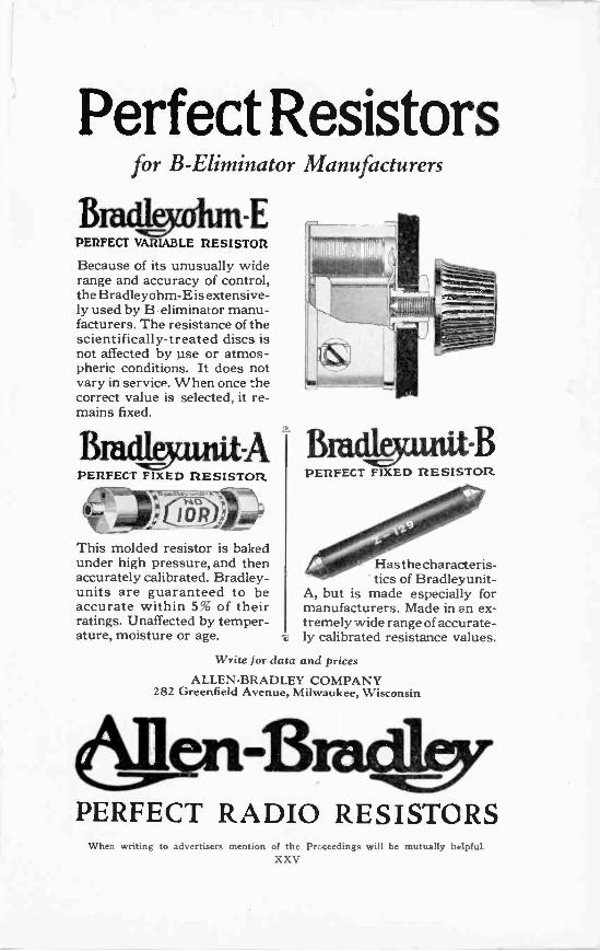
Perfect Resistorsfor B -Eliminator Manufacturers
PERFECT VARIABLE RESISTOR
Because of its unusually widerange and accuracy of control,the Bradleyohm-Eis extensive-ly used by B -eliminator manu-facturers. The resistance of thescientifically -treated discs isnot affected by use or atmos-pheric conditions. It does notvary in service. When once thecorrect value is selected, it re-mains fixed.
PERFECT FIXED RESISTOR
This molded resistor is bakedunder high pressure, and thenaccurately calibrated. Bradley -units are guaranteed to beaccurate within 5% of theirratings. Unaffected by temper-ature, moisture or age. -4;
BPERFECT FIXED RESISTOR
Has the characteris-tics of Bradleyunit-
A, but is made especially formanufacturers. Made in an ex-tremely wide range of accurate-ly calibrated resistance values.
Write for data and prices
ALLEN -BRADLEY COMPANY282 Greenfield Avenue, Milwaukee, Wisconsin
PERFECT RADIO RESISTORSWhen writing to advertisers mention of the Proceedings will be mutually helpful.
XXV
°Alphabetical Index to Advertisements
AAllen-Bradley Co. XXVAmerican Mechanical Laboratories, Inc. XVIIAmerican Transformer Co. IVAutomatic Electric, Inc. XXIV
BBurgess Battery Co. VI
CCambridge Instrument Co. XXVIIICresradio Corporation XVI
DDudlo Manufacturing Corporation XIII
BElectric Specialty Co. XII
FFast, John E. & Co XVFederal-Brandes, Inc. XXIIIFormica Insulation Co. X
GGeneral Radio Co. Back CoverGrebe, A. H. and Co., Inc. Inside Back Cover
HHammarlund Manufacturing Company III
IIliffe & Sons, Limited XXIsolantite Company of America VII
JJewell Electric Instrument Co V
PPolymet Manufacturing Corporation IXPotter Manufacturing Company XIProfessional Engineering Directory XIV
RRadi-Arc Electrical Co. (1927) Ltd. XXIRadio Corporation of America VIIIRadio Engineering Laboratories XXIIRoller -Smith Co. II
SScovill Manufacturing Company XXII
TThordarson Inside Front Cover
Westinghouse Electric & Manufacturing Co XIXWeston Electrical Instrument Corporation XVIIIWireless Specialty Apparatus Co. I
When writing the advertisers please mention The Proceedings ofThe Institute of Radio Engineers.
When writing to advertisers mention of the Proceedings will be mutually helpfuLXXVI
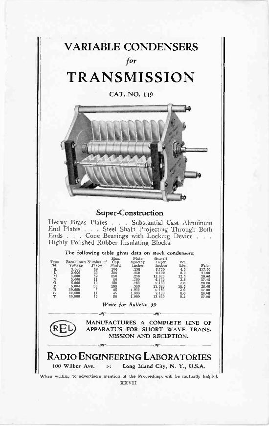
VARIABLE CONDENSERSfor
TRANSMISSIONCAT. NO. 149
Super -ConstructionHeavy Brass Plates . . . Substantial Cast AluminumEnd Plates . . . Steel Shaft Projecting Through BothEnds . . . Cone Bearings with Locking Device .
Highly Polished Rubber Insulating Blocks.The following table gives data on stock condensers:
Max. Plte OverallType Breakdown Number of Cap. Spacing Depth Wt.No. Voltage Plates Mmfd. Inches Inches Lbs. Pri.vK 3.000 19 200 .250 6.750 9.0 617.00L 3,000 33 350 .250 9.L00 8.0 21. SOra 3,000 59 650 .250 13.620 12.5 29.00N 5.000 11 60 .500 6.150 3.5 17.25O 5.000 19 100 .500 9.100 7.0 20.00P 5.000 33 180 .500 13.620 10.5 28.00R 10.000 7 25 1.000 6.150 3.0 17.00S 10.000 11 45 1.000 9.100 6.0 19.1.0T 10,000 19 80 1.000 13.620 9.5 27.00
Write for Bulletin 39
MANUFACTURES A COMPLETE LINE OFAPPARATUS FOR SHORT WAVE TRANS-
MISSION AND RECEPTION.
RADIO ENGINEERING LABORATORIES100 Wilbur Ave. :-: Long Island City, N. Y., U.S.A.
When writing to advertisers mention of the Proceedings will be mutually helpful.XXVII
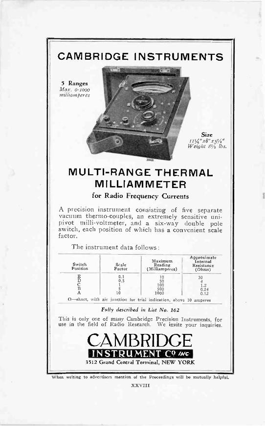
CAMBRIDGE INSTRUMENTS,.--
5 Ranges
milliamperes - .f.:-----ll ! * -a .
...--;
k.... .... ..,,_.*.1.0
s:.%,..
Sizeii 4"x8"2-51/2"Weight 8 lbs.
MULTI -RANGE THERMALMILLIAMMETER
for Radio Frequency Currents
A precision instrument consisting of five separatevacuum thermo-couples, an extremely sensitive uni-pivot milli -voltmeter, and a six -way double poleswitch, each position of which has a convenient scalefactor.
The instrument data follows:Approximatei:terna
MaximumSwitch Scale Reading Resistance
Position Factor (Milliamperes) (Ohms)E 0.1 10 30D 0.5 50 4C 1 100 1.2B 5 500 0.24A 10 1000 0.12
0-short, with air junction for trial indication, above 10 amperes
Fully described in List No. 162
This is only one of many Cambridge Precision Instruments, foruse in the field of Radio Research. We invite your inquiries.
CAMBRIDGEINSTRUMENT CP mc.
3512 Grand Central Terminal, NEW YORK
When writing to advertisers mention of the Proceedings will be mutually helpful
XXVIII
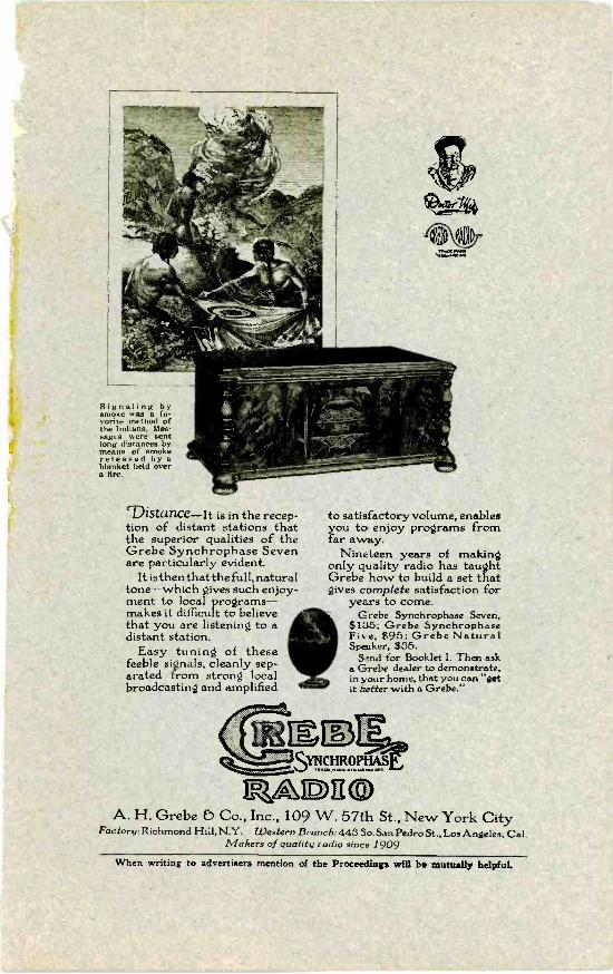
Signaling bysmoke was a fa-vorite method ofthe Indians. Mes-sages were sentlong distances bymeans of smokereleased by ablanket held overa fire.
`Distance-it is in the recep-tion of distant stations thatthe superior qualities of theGrebe Synchrophase Sevenare particularly evident.
It is then thatthe full, naturaltone-which gives such enjoy-ment to local programs-makes it difficult to believethat you are listening to adistant station.
Easy tuning of thesefeeble signals, cleanly sep-arated from strong localbroadcasting and amplified
to satisfactory volume, enablesyou to enjoy programs fromfar away.
Nineteen years of makingonly quality radio has taughtGrebe how to build a set thatgives complete satisfaction for
years to come.Grebe Synchrophase Seven,
$135; Grebe SynchrophaseFive, $95; Grebe NaturalSpenker, $35.
Send for Booklet 1. Then aska Grebe dealer to demonstrate,in your home, that you can ''getit better with a Grebe."
121E1:37t
raarDnoA. H. Grebe b Co., Inc., 109 W. 57th St., New York City
Factory:Richmond Hill, N.Y. Western Branch: 443 So. San Pedro St., Los Angeles, Cal.Makers of quality radio since 1909
When writing to advertisers mention of the Proceedings will be mutually helpfuL
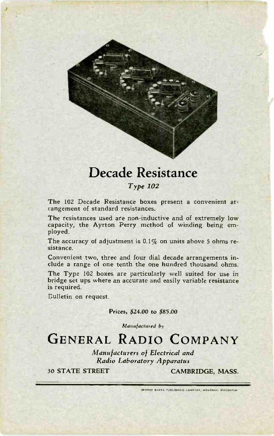
Decade ResistanceType 102
The 102 Decade Resistance boxes present a convenient ar-rangement of standard resistances.The resistances used are non -inductive and of extremely lowcapacity, the Ayrton Perry method of winding being em-ployed.
The accuracy of adjustment is 0.1' , on units above 5 ohms re-sistance.Convenient two, three and four dial decade arrangements in-clude a range of one tenth the one hundred thousand ohms.The Type 102 boxes are particularly well suited for use inbridge set ups where an accurate and easily variable resistanceis required.Eulletin on request.
Prices, $24.00 to $85.00
Manufactured by
GENERAL RADIO COMPANYManufacturers of Electrical and
Radio Laboratory Apparatus30 STATE STREET CAMBRIDGE, MASS.
GEORGE BANTA PUBLISHING COMPANY, MENASHA, WISCONSIN