of forklift truck on side slopes - apps.dtic.mil · analytical analysis for evaluating forklift...
TRANSCRIPT

SI
TECHNICAL REPORT66- 57-NE
COMPUTER ANALYSIS OF FORKLIFT TRUCK
STABILITY WHEN OPERATING ON SIDE SLOPESUNDER NEAR STATIC CONDITIONS
by
Vincent J. DeNinnoI
and
ORDR L x F.Capt. David I Uherka, Pk D.
TECHNICAL INFORIA L lO i
Co~
W June 1966
U ITE ST T S I.MI
Mechanical Eigllmmriug DivisienMNE-12S... ... ... . .... . . . I IN/ II I I Iill I I l I I I I I [ I I • II II II Il II I I !I II II •I IIII

PI$TRIEJTION OF' THIS DOCUMENIT IS UNLIM~ITED.
T~he findings in this report are not to be coasl- i as anofficial Department of the Army position unless so Q,:.;1Agnatedby other authorized documents.
Citation of trade names in this report does not constitutean official indorsement or approval of the use of such Items.
Destroy this report when no longer needed. Do not returnit to the ori#inator.
Di:.tributic-n. of ithi
docuTnent i' unlimited. AD_
TECHNICAL REPORT
66-57-ME
COWPUTER ANALYSIS OF FORKLIFT TRUCK STABILITY WHEN
OPERATING ON SIDE SLOPES UNDER NER STATIC CONDITIONS
by
Vinceent J. DeNinno
Materials Handling Equipment Branch
and
Captain David J. Uherka, Ph.D.Data Analysis Office
Dev Project IM24101D507 Series: .IHE-12
June 1966
Mechanical Engineering Division
U. S. ARMY NATICK LABORATORIES
Natick, Massachusetts

FOREWORD
The studies in this report were conducted by the Materials Handling
Equipment Branch, Mechanical Engineering Division, and the Data Analysis
Office, U. S. Army Natick Laboratories, Natick, Massachusetts, under
Project Number 1M24101D507. Mr. Vincent J. DeNinno served as Project
Officer,ane Capt.David J. Uherka provided the necessary computer data.
The studies summarized in this report represent the development of
a computer program as an approach taken by the Army to provide a rapid
analytical analysis for evaluating forklift truck operation on various
degrees of side slope.
Acknowledgement is accorded to Messrs. W. C. Whittlesey, J. W.
Beaudet, and M. S. Gustin, Mechanical Engineering Division, Mr. Irving
M. Weitzler, Airdrop Engineering Division, and Mr. Ronald J. Geromini
and Lt. Douglas Sanders, Data Analysis Office, for their encouragement
and support of this work. Acknowledgement is also accorded the personnel
of the Data Analysis Office, for the assistance provided in setting up
data and obtaining results from the computer, and to Mrs. Dorothy Uherka
for her contribution in preparing the manuscript for publication.
JAMES H. FLANAGAN
Acting Chief
M4echanical Engineering Livision
APPROVED:
DALE H. SIELING, Ph.D.
Scientific Director
W. M. MANTZ
Colonel, QOC
Commanding
ii
TABLE OF CONTENTS
Page
List of Figures v
Abstract vi
1. Introduction 1
2. Case I. The action Line Method of DeterminingCritical Slope and Orientatio'n 2
a. The Equations for Critical Slope and Orientation 2
b. The Action Line for Rubber-Tired Vehicles 9
3. Case II. Wheel Load Method of Determining CriticalSlope and Orientation 11
a. General Discussion 11
b. The Wheel-Load Equations 14
4. Description of Computer Program 19
a. Case I Vehicles 21
b. Case II Vehicles 24
c. General Flow Diagram 25
d. Input 25
5. Conclusions 27
References 28
Appendixe:s
I. Transformation of Coordinates 29
II. Rotation of a Point About A Line 31
iii

TARTn. OF CONTENTS (cont'd)
III. Transformation of Coordinates for 33Oscillated Vehicles
IV. Listing of Fortran Program 36
V. Example Outputs for Case I and II Vehicles 57
iv
Wptý
LIST OF FIGURES
1. The Suspension Triangle 3
2. Top View of Suspension Triangle 4
3. The Critical Slope Angle, 0 5
4. The Action Line 6
5. Tire Footprints 9
6. Force DI-1tribution on Tire Profile 10
7. Actual Action Line 11
1. Suspension Triangles for Vehicle with 12Midrange Oscillation
9. Moment about a Point 14
10. Moment about a Line 14
11. Standard Position for Input Data 19
12. Suspension Triangle for Rear Axle 22
Oscillation
13. General Flow Diagram 23
Transformation of Coordinates (Appendix I) 29
Rotation aoout a Line (Appendix II) 31
Transformation of x,y Plane to the Plane Containing thm 33Three Tires-; on which the Vehicle is Restinig (Appendix III)
v

ABSTRACT
This report records a method of predicting the static stabilityof vehicles, such as rough terrain forklift trucks, on various typesof slopes by computer analysis.
Two basic methods are used to obtain equations for determiningthe critical slope for a vehicle. These are: (1) the action linemethod, in which the combined center of gravity (CCG) for the vehicleis determined, and the critical slope obtained by finding the sideslopeupon which the vehicle must be resting so that the CCG is directlyover the action llne formed by the two downhill points of support ofthe vehicle, and (2) the wheel load method, in which the loads on thefour tires are examined under all possible sideslope conditions todetermine the minimum slopa for which the vehicle will be in an
unstable condition.
The report includes A computer program using the equations derivedfrom the two methods for determining critical slope-. This progra1allows the vehicle parameters such as type of steer, suspension, frame,weights, and dimensions, to be varied, and for each set of parameters
provides the maximum slope on which the vehicle can rest in a stablecondition. The program also shows the orientation of the vehiclecorresponding to this critical slope.
The computer program follows the wheel load method for vehicleswith midrange oscillation; i.e., vehicles in which the front part canrotate relative to the rear part about a longitudinal axis, with theoscillation joint located somewhere between the front and rear axles.For all other types of vehicles, it uses the action line method.
vi
COPUERANALYSIS~ OF FUtlKLIrL 1fU.Z AJUAg&,A~A&_-
OPERATING ON SIDE SLOPES UNDER NEAR STATIC CONDITIONS
1. Introduction
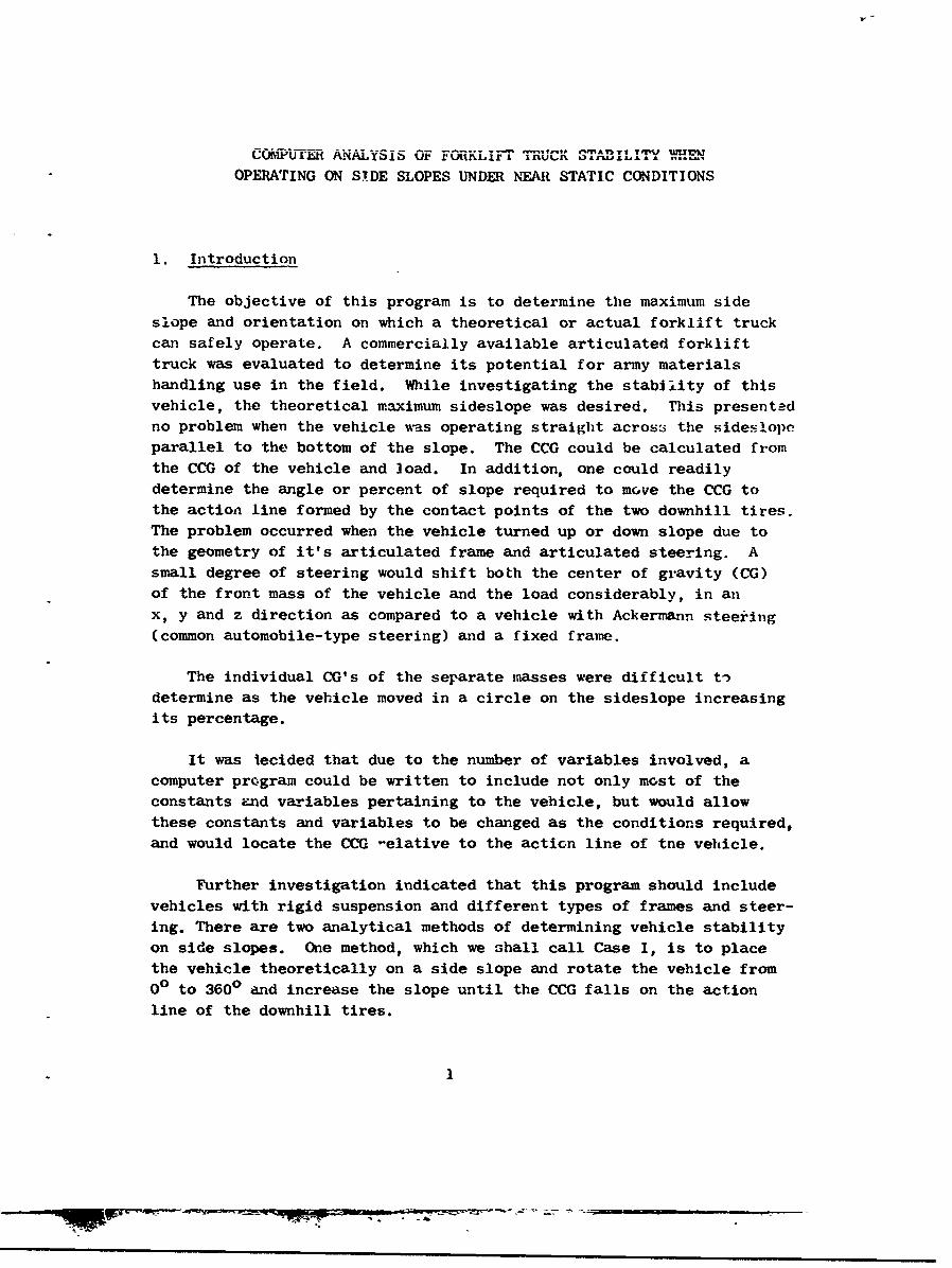
The objective of this program is to determine the maximum side
slope and orientation on which a theoretical or actual forklift truck
can safely operate. A commercially available articulated forklifttruck was evaluated to determine its potential for army materialshandling use in the field. While investigating the stability of this
vehicle, the theoretical maximum sideslope was desired. This presentedno problem when the vehicle was operating straight across the sideslopeparallel to the bottom of the slope. The CCG could be calculated from
the CCG of the vehicle and load. In addition, one could readilydetermine the angle or percent of slope required to move the CCG tothe action line formed by the contact points of the two downhill tires.The problem occurred when the vehicle turned up or down slope due tothe geometry of it's articulated frame and articulated steering. Asmall degree of steering would shift both the center of gravity (CG)
of the front mass of the vehicle and the load considerably, in an
x, y and z direction as compared to a vehicle with Ackermann steering(common automobile-type steering) and a fixed frame.
The individual CG's of the separate masses were difficult tVdetermine as the vehicle moved in a circle on the sideslope increasing
its percentage.
It was iecided that due to the number of variables involved, a
computer program could be written to include not only most of theconstants and variables pertaining to the vehicle, but would allowthese constants and variables to be changed as the conditions required,and would locate the CCG -elative to the action line of tne vehicle.
Further investigation indicated that this program should includevehicles with rigid suspension and different types of frames and steer-ing. There are two analytical methods of determining vehicle stabilityon side slopes. One method, which we shall call Case I, is to placethe vehicle theoretically on a side slope and rotate the vehicle from
00 to 3600 and increase the slope until the CCG falls on the actionline of the downhill tires.

As the CCG approaches the action line, the vehicle becomes more unstableand finally turns over laterally when the CCG passes beyond its limits.This determines both the maximum side slope on which vehicle can operateand its orientation.
The second meth~od, Case II, is to place the vehicle on ahorizontal plane and tilt tne plane in a given directio-: until one ormore of the two uphill tires has a zero wheel loading. The directionof down slope is changed 10 at a time and the process repeated untilcritical slopes are obtained for downihill directions of 00 through 3600.The critical slope and orientation of the vehicle w*Ill be obtained byselecting tha minimum of the critical slopes with its correspondingdOwn slope direction. This will be the maxi~mum side slope and orientationon which the v'ehicle can safely operate.
These twc cases or methods are followed in this report. Case I isused for vehicles with articulated steer, articulated frame, and rearaxle oscillation; Ackermann steer, straight frame and rear axle oscil-lation; and any vehicle in which no oscillation is possible. Case IIis used for vehicles with articulated steer, articulated frame, andmidrange oscillation; and rear axle steer (wagon or Ackermann), straightframe amd mid-range oscillation. This report (Phase 'I) will hand'.le onlythe static conditions where the vehicle is stationary or barely movingon the side slope. A second report (Phase II), p)lanned f or a laterdate, will cover the dynamic conditions where vehicle speed (centrifugalforce) wheel torque, and soil conditions will be considered.
2. Case 1. Thc Action Line Method of Determining Critical Slope andOrientation
a. The Equations for Critical Slope and Orientation
In determining the minimmln degree of slope on wiich a vehicle isunstable, it is assumed that the only forces acting on the vehicle arethose caused by the weight of the vehicle and the load.
In using the action line method of accomplishing the above, wedetermine the minimum slope (and corresponding direction of dowvnslope)for which a given CCG is directly over a given action line, the actionline being a line through two points of support of the mass.
2
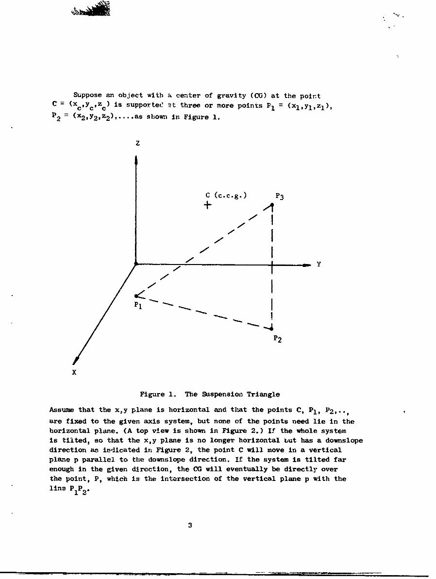
Suppose an object with a center of gravity (CG) at the pointC = (x CYczc) is supportece 't three or more points P1 = (xlY1,z1),
P = (x 2 ,y 2 ,z 2 ), .... as shown in Figure 1.
Z
C (c.c.g.) P 3+
------ 4I
P1 I- | --
x/ S• • P2
X
Figure 1. The Suspension Triangle
Assule that the x,y plane is horizontal and that the points C, P 1 , P 2 ,..,
are fixed to the given axis system, but none of the points need lie in thehorizontal plane. (A top view is shown in Figure 2.) If the whole systemis tilted, so that the x,y plane is no longer horizontal but has a downslopedirection as iriicated in Figure 2, the point C will move in a verticalplane p parallel to the downslope direction. If the system is tilted farenough in the given direction, the CG will eventually be directly overthe point, P, which is the intersection of the vertical plane p with the
line P1 P2
3

P3End view of Averticalplanep p
- (c.cgP.)
DownslopeX direction
Figure 2. Top View of Suspension Triangle
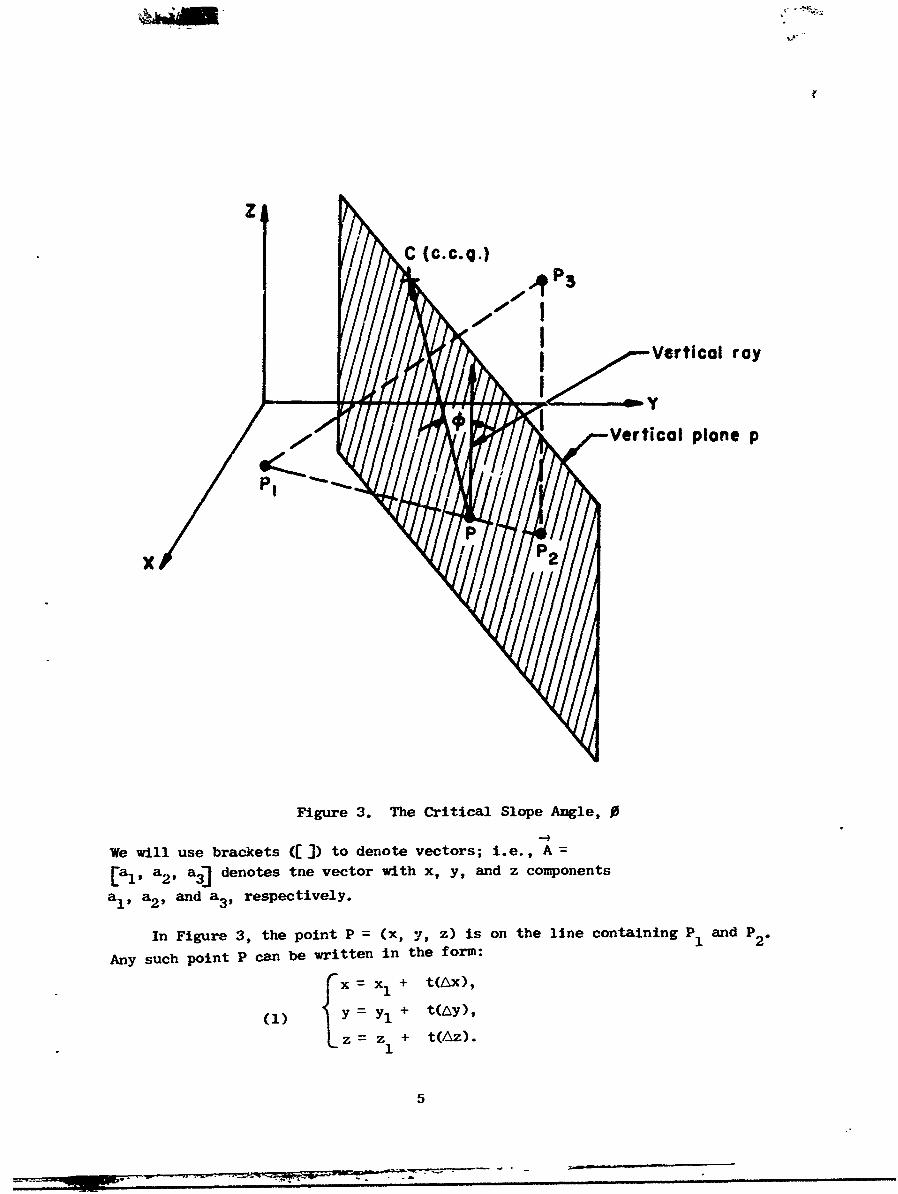
It is evident that the angle through which the system must betilted in order that the point C be directly over the point P, is theangle 0 formed by the segment PC and a vertical ray from P, as shownin Fl.gure 3. Hence, if the system is tilted through an angle 0 in thegiven direction, an unstable condition will exist, since the horizontalprojection of the CG will no longer lie in the interior of the horizontalprojection of the support triengle. (In the figures shown, it is atriangle, but it may be a quadrilateral or some other configuration,depending on the type of suspension of the vehicle.)
In the following discussion, we shall use the notation:
P = (Xl ' YI' Z1 ),
P = (x 2 9 Y2 . z 2 ),
C = (Xc, Yc, Zc),
Ax x X2 - xlI
AY= Y2 - Y
Az = z2 - zI.
4
"Vo
Z
C (c.c.q.)
I roy
/ I/, I Vertical plane p
Pt
x P
Figure 3. The Critical Slope Angle, 0
We will use brackets ([]) to denote vectors; i.e., A[a,1 , a., a 3] denotes tne vector with x, y, and z components
a,, a2, and a3, respectively.
In Figure 3, the point P = (x, y, z) is on the line containing P 1 and P 2.
Any such point p can be written in the form:
xF xx1 + t(Ax),
z =z + t(Az).
5
- -n -

The value of t determines the position of P = (x, y, z) relative to
P1 and P 2; i.e., if t<O, P is on the "dotted" portion of the line
(Fig. 4); if t " 0, P
t.~t
Figure 4. The Action Line
if O<t<l, P is between P1 and P2 ; if t = 1, P = P2 ; and finally if
t>l, P is In the "dashed" portion of the line.
We wish to find an analytical expression for the angle 0 in Figure 3.
We recall from vector analysis that the angle 0 formed by two vectorsA and B is given by:
A . B(2) cos 0 = - -
IAI IBI
-4-4
where A-B is the dot product, and the absolute value symbols denote
vector magnitudes. Hence, the angle 0 in Figure 3 is given by:
(3) cos 0 - (PC)- (Z)
IPcI IZI
where PC =LXc - X, Yc- y, Zc - zjis the vector from P to C, and
Z = [0, 0, l]is the unit vertical vector. Using the fact thatlZ 1 1,
equation (3) becomes:
6

(4) co (zc - z)
(Xc - x)2 F (Yc - y)2 (zc -Z)
Substituting equations (1) into (4), we have:
(5) cos 0 = c - z1 - tAz
v (xc- x 1 - tAx)2 + (yc-yl-tAy) + (zc- z 1-tAz)2
Equation (5) gives the angle 0 for a given value of t; i.e., for a
given point P on the line containing P 1 and P 2 - We wish, however, to
find the minimum angle 0 as P ra,-ges over the given line. We can
accomplish this by maximizing the function of t:
f(t) = Cos 0 zc - z 1 -tAZ
/xc- x 1- tx) 2 + (Yc-Yl-tAy) 2 (c-Zl-tAz) 2
The function f(t) is of the form:
(6) f(t) a + bt
c + dt et2
where a = z -c Z
b = -Az
C (xc - x 1 )2 + (y C Yly)2 + (z- Zl)2
d- -2[AX(Xc - Xl) + dy(yc - yl) + AZ(Zc - Zl)J
e = (Ax) 2 + (hy) 2 (Az) 2 .
Using the usual calculus methods to maximize f(t), we set f'(t) =
0 and solve for t:
(' f'(t) b - (a4ot) (d+2et) 0,
Sc+dt+et 2 (cl-dt'ct 2 ) 2 Ict-dt+et2
7
(8) t = ad - 2bc
bd - 2ac
Hence, if we let to = ad - 2bc
bd - 2an
then the relation
(9) cos 0 a +btA
c + dto + eto2
gives the minitum angle 0 as P ranges over the whole line containingP and P Note that we are not interested in the whole line, but only inthe segment P1 P2 . That is, at this time we are interested only in downslopedirections for which the corresponding vertical plane p, s.hown in Figure 3,intersects the line segment PlP2 . If t0)l, which corresponds to a pointoutside the segment P1 P2 , the minimum 0 for the range in which we areinterested will occur at t1l. Similarly, if to<O the minimum 0 for therange in which we are interested will occur at t = 0. The previous state-ments follow from the fact that the func:tion 0 = 0 (t) is monotonicallyincreasing as t proceeds in either direction from to.
Once we have determined the value t = to corresponding to the minimumslope angle, we can easily find the corresponding downslope direction byfinding the horizontal projection of the vector 4, which lies in thevertical plane p as can be seen frcm Figures 2 and 3. For t = to thishorizontal projection is the vector:
V = Ex-xc, y-yc, OP= Exl+to4x-xc, y1+t0 Ay-y, ojjT -If e is the angle formed by the X-axis and the horizontal vector V, then9 can be determined from the relation:
(10) tan0 = Yl + to Ay - yr
x1 + to 4x - xc
By using the equations obtained in the preceding discussion, one caneasily find the critical slope and downslope direction relative to a givenCG and action line. Usually one must consider several action lines whenstudying the static stability properties of a given object, the actionlines being determined by the points of support for the object in question.
8
/

The overall critical nlepe would be the minimum of the critical slopes
relative to the various action lines, and the overall critical down
slope direction would be the down slope direction corresponding to theoverall critical slope.
b. The Action Line for Rubber-Tired Vehicles
A vehicle with low pressure rubber tires is not supported
by contact "points" but rather by contact "areas," namely, the tire"footprints." If we are to use the action line method of determining
critical slope for such a vehicle, we must make a reasonable assumptionof what point in the footprint of a tire to take for the end point of an
action line (Fig. 5).
P1 P2Tire Footprints
Figure 5. Tire "Footprints"
One method might be to take the center of the footprint for an end pointof the action line. However, we must remember that the true action lineis the line about which the vehicle will rotate once the CCG passes over
this line. Consider a vehicle on a sideslope and suppose that the vehicleis in an unstable condition; that is, at this moment the vehicle has nottipped over, but if the slope were increased by a small amount (in the
existing downslope direction), turnover would occur. In this case, thevehicle would be balanced on the downhill tires with zero load on the uphilltires. The situation would be similar to that depicted in Figure 6.
If we take moments about a line L directly under the COG and passingthrough the tire footprints (Fig. 7), the resultant moment about this linemust be zero since the vehicle is assumed to be in equilibrium.
9

Let A and Fs denote the respective p-jct Onof the I
onto the plane of the lslope. Then, for our assumed equilibrium
condition the line segment AB cannot lie directly under the
+ CG
..----- IWheel
II
DownhillTire
Compressed
Stretched
Figure 6. Force Distribution on Tire Profile
COG, for if AB did lie directly under the COG, the moments tending to
cause turnover about the line AB would be greater than the moments
acting in the opposite direction. This would happen since the
10
/
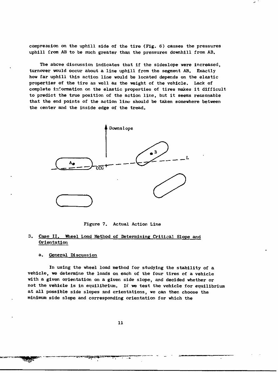
compression on the uphill side of the tire (Fig. 6) causes the pressures
uphill from AB to be much greater than the pressures downhill from AB.
The above discussion indicates that if the sideslope were increased,
turnover would occur about a line uphill from the segment AB. Exactlyhow far uphill this action line would be located depends on the elasticproperties of the tire as well as the weight of the vehicle. Lack ofcomplete information on the elastic properties of tires makes it difficultto predict the true position of the action line, but it seems reasonablethat the end points of the action line should be taken somewhere between
the center and the inside edge of the tread.
Downslope
I *BA__ ._- _--L
Figure 7. Actual Action Line
3. Case II. Wheel Load Method of Determining Critical Slope and
Orientation
a. General Discussion
In using the wheel load method for studying the stability of avehicle, we determine the loads on each of the four tires of a vehiclewith a given orientation on a given side slope, and decided whether ornot the vehicle is in equilibrium. If we test the vehicle for equilibriumat all possible side slopes and orientations, we can then choose theminimum side slope and corresponding orientation for which the
11

vehicle is not in equilibrium. This will give the critical slope andorientation for the vehic]e under consideration.
Usually the wheel loads (in a condition of equilibrium) aredetermined by solving the equilibrium equations for the unknown forceson the tires. For a given side slope and orientation, we will assumethat the vehicle is in equilibrium and compute the wheel loads fromthe equilibrium equations. The forces on the tires obtained will be
the forces necessary for equilibrium to exist. If, in reality, thevehicle is not in equilibrium, one of the computed forces will be actingin a direction physically impossiblo for our system; i.e., our resultswill tell us that the system will be in equilibrium provided we apply
an additional downward force to one of the uphill tires, which isequivalent to saying the system is not in equilibrium as it stands.
In using the wheel load method we shall c-nsider vehicles in wh±chmidrange oscillation is possible; i.e., at some point between the frontand rear axles the front part of the vehicle can rotate, relative to therear part of the vehicle, about some fixed axis. Assume the vehicle iscomposed of two rigid bodies joined at one point J so that the two bodiescan rotate relative to one another about some fixed axis L passingthrough the common point (Fig. 8);
Front
Oscillation axis
G TW wooF
W JaCommon point
F3
Figure 8. Suspension Trianglesfor Vehicle with Midrange Oscillation
12
t /

Since we are concerned here with only static stability where thewialy external f•.rcc -.e those caused by the weight of the vehicle, we willassume that the resultant reaction forces acting on eac-h of the four tiresare vertical. In the following analysis, we will assume that the coordinateaxes are chosen in some convenient manner so that the x,y plane is horizontal.Assume that the vehicle is resting on some plane, with the tire loadscentered at the points R. (xi Yi zi), i ], 2, 3, 4, where It and It)
I ' i i 1refer to the front tires and H3 and 114 refer to the rear tires. (AOrnotation will be as follows:
W, -weight of the front part of the vehicle, including
load,
Rcl = (Xcl, Ycl, Zcl) = center of gravity of the front part of
the vehicle,
w2 = weight of the rear part of the vehicle,
Rc2 (xc2, Yc2, zc 2 ) center of gravity of the rear part
of the vehicle,
w - wI ± w2 total weight of the vehicle,
Re = (Xe, Yc, Zc) = combined center of gravity of the vehicle
where Xc = XcI (Wl/W) + Xc (w 2 /w), Yc ycl (wl/w) -:" Yc, (w2 /w), and
zc = Zc1 (w1/w) + Zc 2 (w 2 /w),
Fi = L0, O, Fi the vector representing the vertical reaction
force acting on the ith tire at the point Ri; i = 1, 2, 3, 4,
Wi =LO, 0, O -wij = the vector representing the weights of front
and rear parts of the vehicle, acting at the points R respectively;
i = i, 2,
W = CO. 0, -wj. = the vector representing the total weight ofthe vehicle, acting at the point Re.
If A denotes the point (a,, a2, a 3 ), then A will denote thevector [a1, a 2, a3] representing the directed segment from the origin
to the point A. We recall from the Principles of Mechanics(2) that if
13

-+ -4
F is a ferce acting at a point B, then the vector moment of F about apoint A is given by:
M ABXF
whare AB is the vector from A to B and the symbol :!XIV denotes the vector
cross product (Fig. 9). We recall also that if L is a line containing
A and•j is a unit vector parallel to L, then the scalar moment of
about the line L (with the
A F
Figure 9. Moment about a Point
positive direction determined by U) is given by (Fig. 10).
M = U • (AB X F)
B
Figure 10. Moment about a Line
b. Wheel-Load Equations
We shall now obtain the equations for the wheel loads Fi,i =1, 2, 3, 4. Assume that our vehicle is resting on a slightly
tilted plane, in a condition o- equilibrium.
14
i,2)A necessary conditioui or the system to be in equilibrium is that:
-- ) -- 3
(1) F = 0 and
(2)
where F is the sum of the applied forces acting on the systemand G is the oum of the applied moments about some fixed point, say the
origin. For our system, equations (1) and (2) are respectively:
-P. 4 -all(3) F =2 F,+ V =0,
i :'
4
(4) G Ri X Fi R C' X W 7 0.*1
Upon examining the individual components of the vectors inequations (3) and (4), we find that (3) reduces to the scalar equation
4(5) 4F = w,
i= 1
and (4) reduces to the two scalar equations
4
fl xi Fi w Xc,j-:j
(6)4
I y FYi w YC"
Li 1
Our system of equations for the determination of the F is:i
C--F F9 + F3 + F4 - w
F + x 2 F 2 + x 3 F3 + x4 F4 w x(7) c
yl F1 + y2 F 2 + y 3 F3 + Y4 F4 w y.c
15

We can assume that the three equations in (7) are indepenaent since a
3 X 3 determinant from the coefficient matrix
x xI x2 x 3 x 4
YI Y2 Y3 Y4
is zero only if three of the points R1 , R2 , R3, R4 are collinear
which certainly will not be the case for any vehicle we wish to consider.Any three of the Fi can be obtained in terms of the fourth Fi from (7);
however, we cannot get a unique solution from the system of three equationsin four unknowns. Therefore, we have not supplied enough information touniquely determine the Fit and we must look for a fourth equation in the
Fi. The fourth equation comes from the fact tnat the vehicle is composed
of two rigid bodies which can rotate relative to one anotler about a
fixed axis L. If the vehicle is to be in equilibrium, then the resultantscalar moment of the front part of the vehicle about the axis L must bezero. If J = (xj, yj, zj) is the common point in Figure 8, andU =iu, u 2 , u@ is a unit vector parallel to L and directed toward thefront of the vehicle, then the resultant scalar moment of the front partof the vehicle about L (with positive direction determined by U) is given
by
(8) m U-(JR1 X FI) + R 2 X71 + -'
Ul u 2 u 3 + u2 3 U .u 2 u 3
xl-XJ Yl-Yj Zl-ZJ x2-xJ Y2-YJ z2-z1 J YCl-YJ ZC-I-
0 0 F 1 J 0 0 F 2 0 0 -w 1
F1 xlj y1 j ~+ F~ -X YjFI-XJ Yu- F2 x 2 j Y2-YJi xcl-xJ Yc1Ij
F F1 dI + F 2 d2 -WIdc , where
16
Ul U2L1U u2 I "I 112 I
d = xl-X yl-y-j d, X,-xJ y2?-yj , and
uI u2dcl1 x c 1xj Y l-J
Setting the scalar moment m in (8) equal to zero, we obtain the equation
(9) dlF1 + d2F2 w1 d
Hence, (7) and (9) give the following system of four equations
in four unknowns:
d 1 F- d 2 F 2 w 1WdCl
FI- r I F ± F w1 2 3 4
(10) X F I x2F2 F x3F3 .x4F4 w xc
yF1 y 2 F 2 + y 3 F 3 + y4 F4 WC.
Note that equations (10) force the resultant scalar moment ofthe rear pare of the vehicle about L to be zero also, since the forward
moments about L are zero and since equations (1) and (2) require thatthe sum of all the moments about L be zero.
Equations (10) can easily be solved for the Fi, by means of
determinants. The solutions to (10) are as follows:
(11) Fi = Di/D for i=1,2,3,4, where
D = determinant of coefficients
= d1 [(x 3 -x 2 ) (y 4 -y 2 ) - (x 4 -x 2 ) (Y 3 -Y 2 )]
- d 2 [(x 3 -xl) (y 4 -y,) - (x 4 -x 1 ) (Y 3 -Y 1 )I,
D -- Wld1 [(x 3 -x2) (y 4 -y 2 ) - (x4-x 2 ) (Y 3 -Y 2 )]
- w d2 [(x 3 -xc) (y4-yc) - (x 4 -xc) (3yac,
17
7___o -

D2 =w dI [(x 3 -xc) (y 4 y) - (x 4 -xc (y)3-Yc]
-wd (x (y- 1 - 4y-
3 w d1 [(xc-x2) (y 4 -y 2 ) - (x 4 -x 2 ) (yc-Y2)]
- w d 2 [(xc-X1) (y 4 -y 1 ) - (x 4 -x 1 ) (yc-Y11]
+ WIdCI[(x 2 -x1) (y 4 -yl) - (x 4 -xI) (Y 2 -Yl)]
D 4 w dl [(x 3 -x 2 ) (Yc- Y2 ) - (xc-x 2 ) (y 3 -y 2 )]
- w d 2 [(x 3 -x 1 ) (yC- Y1 ) - (xc-x 1 ) (Y 3 -Yl)]
- Wd CJ[(x2-x ) (y 3 - Yl) - (x 3 -x 1 ) (Y 2 -Yl)]"
The unit vector U= [U, u 2 , u 3 ], in (8), which is parallel
to the oscillation axis L, can be determined if we know two points
P and Q on the line L. If P = (xp, zp) and Q = (x Q, yQ, z0)
are on L and PQ is directed toward the front of the vehicle, tnen
we can let U be the unit vector:
U = PQ/IPQI) PQ
1 XQ-xp, YQ-Yp, ZQ-Zp].
] (XQ-Xp) 2 + (YQ-Yp) 2 + (ZQ-Zp) 2
After examining equations (8), (9), and (11) we see that the factor
(i/j•j) inV will appear as a factor in the numerator and denominator
in (11) and hence will cancel out. Therefore, to simplify calculations,
we can take U PQ to determined d 2t and dd
18
4. Description of Computer Program
A computer program which calculates critical slopes and
orientations for various types of rigid-suspension vehicles, uses the
action line method (Case I) for the following types of vehicles:
(a) articulated steer, articulated frame, and rear axle oscillation,
(b) Ackermann steer, straight frame, and rear axle oscillation, and
(c) any rigid-suspension vehicle on which no oscillation is possible.
The program uses the wheel load method (Case II) for any rigid-
suspension vehicle having midrange oscillation (as described in Section 3).
In case oscillation car occur, the program computes critical slopes
for oscillation and turnover. A general description of the computer
program is given in the following paragraphs. If more details are
desired, a listing of the Fortran program is given in Appendix IV.
A general flow diagram is shown on page 30 in this Section (Fig. 13).
T'e basic notation used in the computer program is shown in
Figure
Y
'ront tires
S(L
kC-F
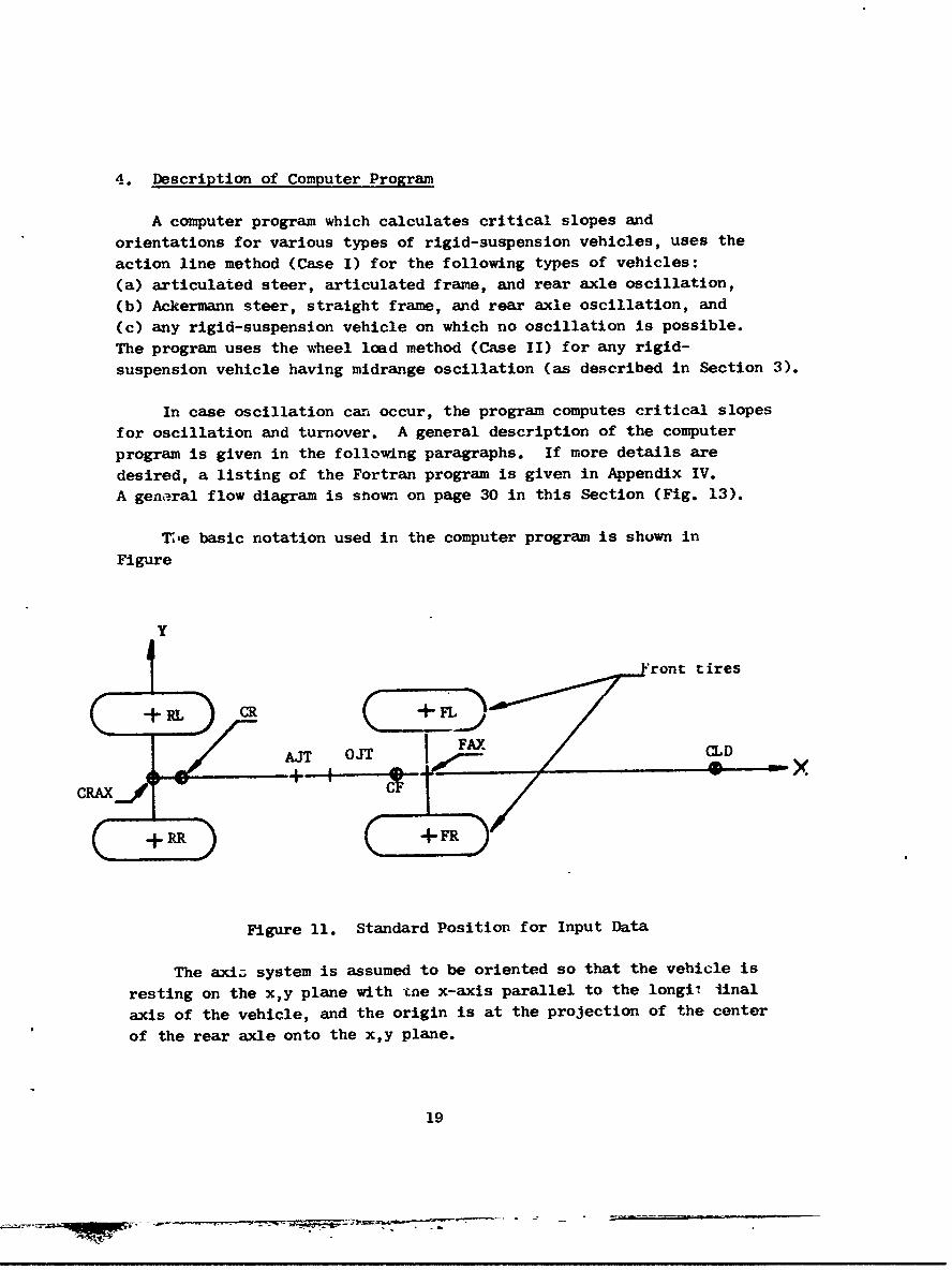
Figure 11. Standard Position for Input Data
The axiz. system is assumed to be oriented so that the vehicle is
resting on the xy plane with tne x-axis parallel to the longil linal
axis of the vehicle, and the origin is at the projection of the center
of the rear axle onto the xy plane.
19

The variable names as used in the program, and their meanings areas follows:
FL, FR, RR, RL: Centers of the bearing surfaces of the four tires:front left, front right, rear right, and rear left, respectively.
AJT: Center of the articulation joint.
OJT: Center of the oscillation joint.
FAX: Center of the front axle.
CF: CG of the front mass of the vehicle.
WF: Weight of the front part of the vehicle.
CLD: CG of the load.
WLD: Weight of the load.
CXF: CG of any extra mass added to the front part of the
vehicle.
WXF: Weight of any extra mass added to the front part of the
vehicle.
CR: CG of the rear mass of the vehicle (minus the rear axle).
WR: Weight of the rear part of the vehicle (minus the rearaxle).
CRAX: Center of the rear axle (also the CG of the rear axle).
W•AX: Weight of the rear axle.
CXR: CG of any extra mass added to the rear part of the vehicle.
WXR: Weight of any extra mass added to the rear 1.art of thevehicle.
ALPHA: Steer angle (always assumed to be such so that thevehicle will turn left if ALPHA is positive).
20

OSC: The oscillation angle; i.e., the angle through which thefront (or rear) part of the vehicle can rotate from the neutral positionbefore hitting the mechanical stop.
SHIFT: Distance from the center of the tire tread (toward theinside edge of the tread) so that the endpoint of the action line willbe located.
NSTEER: Equals 1 if the vehicle has articulated steer; 2 ifrear wagon wheel; and 3 if Ackermann.
NOSC: Equals 1 if no oscillation is possible; 2 if rear axleoscillation is possible; and 3 if midrange oscillation is possible.
Weights and distances can be expressed in any convenient unitsas long as the same units are used throughout. However, it is suggestedthat weights be expressed in lbs since the output column headingsare labeled "ibs" for Case II vehicles.
The symbols defined above which represent locations (in space)are actually arrays,each consisting of the three coordinates of thelocation. Details on the formats and arrangement of the input datacards are givAn in Section 4.d.
During execution of the computer program, the computer firstreads in the data for the vehicle in standard position as shown inFigure 11. The coordinates are then recomputed as necessary dependingon the type of steer and angle of steer. The computer then followsone of two possible sequences of events depending on whether or rotmidrange oscillation is possible.
a. Case I Vehicles
This part of the program pertains to vehicles which donot have midrange oscillation.
(1) For a vehicle in which no oscillation is possible,the computer first calculates the combined CG of the whole vehicle,using the usual moment equations which can be %btained from any mechanicstestbook. The computer then calculates the critical slopes relative toeach of three action lines; that formed by the left two tires; by theright two tires, and by the front two tires. It is left to the personusing the program to decide which of the three slopes is the minimum.
21
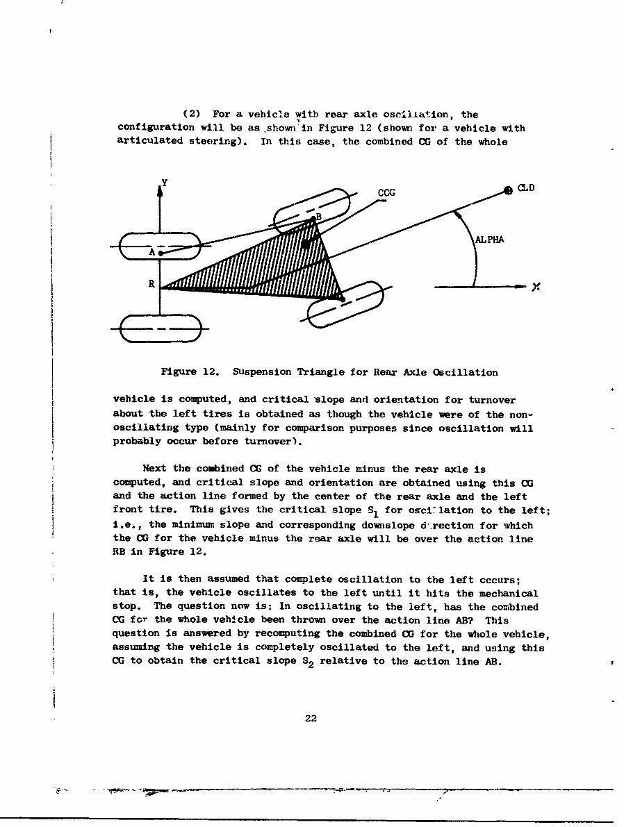
(2) For a vehicl.e with rear axle oscillation, theconfiguration will be as.shown'in Figure 12 (shown for a vehicle witharticulated steering). In this case, the combined CG of the whole
SCCG CLD
Figure 12. Suspension Triangle for Rear Axle Oscillation
vehicle is computed, and critical slope and orientation for turnoverabout the left tires is obtained as though the vehicle were of the non-oscillating type (mainly for comparison purposes since oscillation will
probably occur before turnover).
Next the combined CG of the vehicle minus the rear axle is
computed, and critical slope and orientation are obtained using this CGand the action line formed by the center of the rear axle and the leftfront tire. This gives the critical slope S1 for osci:'lation to the left;
i.e., the minimum slope and corresponding downslope d'rection for whichthe (G for the vehicle minus the rear axle will be over the action lineRB in Figure 12.
It is then assumed that complete oscillation to the left cccurs;that is, the vehicle oscillates to the left until it hits the mechanicalstop. The question now is: In oscillating to the left, has the combinedCG for the whole vehicle been thrown over the action line AB? Thisquestion is answered by recomputing the combined CG for the whole vehicle,assuming the vehicle is completely oscillated to the left, and using thisCG to obtain the critical slope S2 relative to the action line AB.2
22

Then, S i .. .S ha- + 1 turnovercouln not have occurred when
the vehicle oscillated, for the critical slope for ai oscillated vehicleis, in this case, greater than the slope at which oscillation occurs. On
the other hand, if S2 is less than SI, turnover can occur when the vehicle
oscillates, because the critical slope for turnover of an oscillated vehiclewill nave already been surpassed when the slope is reached at which
oscillation occurs.
The above discussion indicates that if S2 is greater than SI,
turnover will occur at slope S2 , while if S2 is less than SI, turnover
can occur at slope SI. In other words, the actual critical. slope for
turnover will be the maximum of Sl and S2.
Next, a similar procedure is used for oscillation and turnover to
the right.
Finally, turnover over the front axle is obtained in a mannersimilar to the non-oscillating case.
The equations for transformation of coordinates, used in obtainingthe combined CG for an oscillated vehicle, are discussed in Appendixes I,II, and III.
b. Case II Vehicles
This part of the program concerns vehicles with midrangeoscillation. In case the vehicle has midrange oscillation and arti-culated steering, it is assumed that the oscillation joint OJT isimmediately in front of, or immediately to the rear of, the articulationjoint AJT. For a vehicle with midrange oscillation and rear wagon wheelor Ackermann steering, the oscillation joint OJT can be anywhere betweenthe rear axle and the front axle.
Once the computer learns that the vehicle under considerationhas midrange oscillation, it goes through the following steps. Thecomputer first calculates the CG and weight of the front part of thevehicle, the CG and weight of the rear part of the vehicle, and thecombined CG and votal weight of the vehicle.
The computer then varies the downslope direction 0(measured counterclockwise from the positive x-axis) from 0 degrees to360 degrees, one degree at a time. For each downslope direction 0,
23

the plane on which the vehicle is resting is tilted in the direction 0
until at least one of the fokir wheel-loads (as calculated by the method
described in section 3), becomes zero. Thus, for each downslope direction
0 we obtain the critical slope angle 0. For 0, the computer prints 0, 0,tan(0) in percent, and the four wheel-loads corresponding to the downslope
direction 0 and the slope angle 0. If, for a given e and 0, only one of
the upslope wheel-loads is zero, we can assume that we have a situationwhere oscillation is about to occur. If two (or three) of the uphillwheel-loads are zero, then we have a situation where turnover is about
to occur. After the table of values for 0, 0, tan(O), and the wheel-loads, is obtained, the table can be examined to determine which down-
slope directions give oscillation and which ones give turnover, and the
corresponding minimum slopes can be obtained for each case.
After obtaining the table of critical rlopes using the wheel-loadmethod, the computer finds critical slopes Ior turnover of an oscillated
vehicle by assuming that the vehicle is completely oscillated and is
resting on three tires with the fourth tire off the ground. Four
critical slopes for turnover are obtained by assuming that each of the
four tires are, In turn, iff the ground. These four values can be
examined to determine whether or not the vehicle will turn over whena slope is reached such that oscillation occurs.
Example outputs for both Case I and Case II vehicles are givenAppendix V.
c. General Flow Diagram
The diagram shown in Figure 13 gives a general idea of themain sections of the computer program.
d. Mut
In this section we will give a description of each of the21 input cards for the Static Stability Study computer program. The
first card is a heading card, and the second and third cards enable thecomputer to decide which of the 18 vehicle data cards (cards 4 through
21) are to be read.
24

RE.A)I~rn/START
ICH FORTYPE RECNLELcTTEOF STEER COORDINATES
NONECHLECF AND E OF MIDRANGE
I- _.REAR AXLE
FOR DOWNSLOPE TO THE1 LEFT AND RIGHTi,
CALCULATE: -
CALCULATE CVARY DOWNSLOPEICALCLTES 1. CRITICAL SLOPE DIRECTION ANDCRITICAL SLOPESFOR TURNOVER WITHOUT CALCULATEFOR TURNOVER TO OSCILLATION CRITICAL SLOPESLEFT, TO RIGWJT, BY WHEEL-LOAD
AND FORWARD 2. CRITICAL SLOPE METHOD
FOR OSCILLATION
3. CRITICAL SLOPEFOR TURNOVER AFTEROSCILLATION
CALCULATE
CRITICAL SLOPESFOR TURNOVER
CALCULATE AFTER OSCILLA-CRITICAL SLOPE TIONFOR TURNOVEROVER THE FRONT
AXLE
YES ARE 44•
S~CASES
Figure 13. General Flow Diagram
25

(1) Card 1 contains the heading, vehicle description, orany other desired information pertaining to the run. All 80 columns
of this card will be printed as the first line of output.
(2) Card 2 contains (right justified in columns 1 and 2)the integer NCD = the number of vehicle data cards to be read. If NCD =
18 (the maximum number of vehicle data cards), then card 3 must be omittedand all 1i vehicle data cards will be read in order.
If NCD = 0 (i.e., if card 2 is blank), then the program will
stop.
(3) If 0 <NCD<18, then card 3 must contain the integers
n1 , n 2 -. . . . . n NCD; where nI is right justified in columns 1 and 2,
n2 is right justified in columns 3 and 4, and 13 is right justified in
columns 5 and 6. The computer will then read the vehicle data cardswith identification numbers n1 , n 2 ,..., nNCD, respectively.
If NCD = 18, card 3 must be omitted.
The 18 vehicle data cards contaip information as follows. Theparentheses indicate the dimension of a variable; for example, FL(3)indicates that thz card is to contain the three coordinates of thepoint FL.
(4) Data card #. FL(3)(5) Data card #2: FR(3)(6) Data card #3: RR(3)(7) Data card #4: RL(3)(8) Data card #5: AJT(3)(9) Data card #6: OJT(3)
(10) Data cardl #7: FAX(3)(11) Data ca.'d #8: CF(3), WF(12) Data ce-rd #9: CLD(3), W.D(13) Data card #10: CXF(3), WXF(14) Data card #11: CR(3), WR(15) Data card #12: CRAX(3), WIRAX
(16) Data card 91?: CXR(3), WXR(17) Data card #14: ALPHA, in degrees(18) Data card #]5: OSC, in degrees(19) Data card #16: SHIFT(20) Data card #17: NSTEER
(21) Data card #18: NOSC
26

On data cards #1 through g16, ten columns are allowed for eachvalue. Each value should contain a decimal point (on data cards #1through 916) and should be right justified in its respective ten columns.Hence, 30 columns will be used on data cards #1 through #7, 40 columnswi]l be used on data cards 98 through #13, and 10 columns will be usedon data cards #14 through #16.
On data cards #17 and #18, the integers NSTEER and NOSC are
punched in column 1.
For a given run, the number of vehicle data cards present isgiven by NCD on the second input card. The vehicle data cards whoseID numbers are not included in the list n., n2, . . . . , nNCD (if NCD (18)
should be omitted.
For further details on the input formats, the program listingshould be examined (Appendix IV).
5. Conclusions
The methods discussed in this report should be adequate for study-ing the static stability properties of many types of rough terrainvehicles. It should be realized, however, that the methods used hereinare based on equations for rigid mechanical systems and cannot beexpected to give results that agree completely since most vehicles tobe considered will be of the low-pressure, rubber-tired type. Itshould be remembered that in most cases the center of a wheel loadwill be several inches uphill from the center of the correspondingtire footprint. Lack of knowledge about the exact location of thecenter of the wheel load could quite easily lead to computer results.However, it is expected that, through careful calculations of thecenters of the wheel loads, results will be obtained which agree quiteclosely with experimental data.
Since the computer program is much faster when the action linemethod is used as compared with the wheel load method it Awa hopedthat every type of vehicle could be analyzed by the action line method.However, it was discovered that this method would not work for avehicle with midrange oscillation; that is, one cannot determine thecritical slope for oscillation to occur for a vehicle of this type!therefore, it was necessary to go to the wheel load method for vehicleswith midrange oscillation to determine when oscillation would occur.
27
The present computer program, which utilizes both methods, requires about8,000 twenty-bit words of memory. Any increase in the 3ize of thepresent program would cause the program to overflow the memory of manyof the smaller computers.
It is anticipated that, through use of the accompanying computerprogram, the objective of obtaining a more efficient method of analyzingthe static stability properties of rough-terrain vehicles will be accom-plished. In addition to analyzing existing vehicles, the computerprogram should prove quite useful in designing vehicles by'providing arapid means of conparing the static stability properties of two or moreproposed vehicles.
If it is decided to make a study of the dynamic case in which drivingforces, acceleration forces, and centrifugal forces must be taken intoaccount, a modification of the wheel load method will probably be mostsuccessful for this situation since the wheel-load equations can beadapted without to much trouble tu handle additional applied forces.
It is hoped that the material contained in this report will proveuseful to those wishing to analyze the static stability properties ofrough-terrain vehicles.
6. References
Handbook of Chemistry and Physics, 37th Edition, Hodgeman: Editor inChief, Chemical Rubber Publishing Co., Cleveland, 1955, pp. 327-329.
Synge and Griffith, Principles of 1,echanics, McGraw-Hill, New York,1959.
28

APPENDIX I
TRANSFORMATION OF COORDINATES
The matrix equation[i]for transforming the coordinates (p,' P2, P 3 )
of a point P with respect to the x,yz axis system to the coordinates
(PI, P 2, P 3 ) of the same point with respect to the x , y, z axis system
(Fig. 1.) is as follows:
(1) P' = T(P-Q), where
Z ZI
New Axes
P (P.I'P2'P3 (ql(q q2 q3 )
Old Axes
I ,
x
Figure 1. Transformation of CoordinatesP A\P J where pl, P 2 , P 3 are the coordinates of 2 with
respect to the old axis system;
29

Q = q2 ) where ql, q2, q3 are the coordinates of the
q3/
new origin with respect to the uld axis system;
t
"p1
P = P2 where P' are the coordinates of P with
whr 1, P2, P
P3
respect to the new axis system;
tl tl t
T t21 t22 23 , where t~l, t 1 2 , and t 1 3 are the
t t t31 32 3
tt
direction cosines of the x axis relative to the x, y, and z axesrespectively; t21, t22, t23 are the direction cosines of the y'
axis relative to the x, y, and z axes respectively; and t 3 1 , t 3 2 , -*33
are the direction cosines of the z' axis relative to the x, y, and z
axes respectively.
Written in scalar form, equation (1) becomes:
p1 tll(pl-ql) + tl 2 (P 2 -q 2 ) + t 1 3 (P 3 -q 3 )
(2) p2 t 2 1 (pl-q!) + t 2 2 (p 2 -q 2 ) + t(P-q3
p 3 = t 3 1 (Pl-ql) + t 3 2 (p 2 -q 2 ) + t 3 3 (P 3 -q 3 )"
These equations are used in the Static Stability Study computer program
whenever it is nlecessary to transform coordinates from one axis system to
another.
30

APPENDIX TT
ROTATION OF A POINT ABOUT A LINE
In recalculating coordinates in the Static Stability Study
computer program, it is quite often necessary to rotate a point Xo
about a line. Here, we describe the equations used to find the point
X1 into which the point Xo is rotated.
Consider, as in Figure 1, the line L determined by the point J
and the unit vector U. Suppose that the point Xo is rotated about the
line L by an angle where positive rotation is taken to be such that-4•
the right hand rule will give a direction parallel to U.
L"z X
mob
-t P X
Figure 1. Rotation About A Line
The problem is to find X1 , the point into which Xo is rotated.
Let P be the projection of Xo onto the line L. We wish to find P
in terms of known quantities, Since J and P are on the line L, the
vector P - J must be parallel to L, i.e.,
31

where k is a scalar which we must determine.
Since X - P is perpendicular to U, it foll:,- that
(2) (Xo - P) * U 0
substituting P J + kU into (2), we obtain (Xo -J) U - kU-U
0, or
(3) k (Xo -J) U -
since U is a unit vector and hence U U = 1. Therefore, from(1) and (3), we have
(4) P = J --P -J) " 1 U.
Now if a perpendicular is dropped from the point Xi to the segment
PX0 , and if use is made of the iact thatlXo -p| = -- •j , it can
readily be seen that the vector Xl, from the origin to Xl, is given by
-41. -PI -01 -01 -+ -. -b(5) X1 = P + (cos-"%-) (X0 - P) + (sin.•U X (Xo-P).
Hence, we have X1 in terms of known quantities.
Equations (4) and (5) are used in subroutine SROT of the computerprogram to recalculate coordinates of a point on a vehicle after part
of the vehicle is rotated relative to the rest of the vehicle.
32

APPENDIX III
TRANSFORMATION OF COORDINATES FOR OSCILLATED
VEHICLES
In computing turnover slopes for an oscillated vehicle, the
computer program assumes that the vehicle is resting on three tires.
We will describe the method used to transform coordinates so that the
x,y plane contains the three points on which the vehicle is assumed
to be resting.
The prob• em is as follows:
Given three points A, B, C as in Fig. 1, find the transformation
equations so that
(1) the new origin is the midpoint of the segment AB,
(2) the new y-axis contains the segment AB,
(3) the new z-axis is perpendicular to the plane ABC., and
(4) the new x-coordinate of C is positive (or negative,
as desired),
A<
Figure 1. Transformation of x,y Plane to the Plane
Containing the Three Tires on Which the Vehicle is Resting
33

Conditions (1) through (4) are set up so that the points A, Bwill be the rear tires if the new x-coordinate of C is to be positive;
otherwise tne points A, B wili be iLhe front tires.
Let X, Y, Z denote the direction co.;ine vectors of the three newaxes respectively, relative to the old axes. We wish to find X, Y,
andi. Let
Y 1 0= ' and
(5)- - -.- - -I (C - A) X (B - A) = (C - A) X Y
Then Y and Z have the correct directions (for the case shown in
Figure 1), but they are not unit vectors, as direction cosine vectors
must be. Therefore, we set
-' l! Y= 11 ll)Y1,(6) = (1/ -*I ) a= (l/ )Z1I , and
Then X, Y, and Z are the required direction cosine vectors if we wish
the new x-coordinate of C to be positive.
If we wish the new x-coordinate of C to be negative, then insteadof equations (6) we must use
= (1/|Y l)YI.,
(7 Z (-l/ ZlI)Z 1 , and
In general, once we have obtained Y and Z, from (5), we can get-am -9- -9-
X, Y, and Z from
y = )I
(8) = (S/fZll)ZI, and
=-X Y X ,
where S= 1 or -1 depending on whether we wish the new x-coordinate
of C to be positive or negative.
34
"*"'- - - --

-- 4 -*A %Once we have X, Y, and Z from (8), we can translorm any point using
the equations described in Appendix I, where X, Y, and Z are the first,secuI, au thirdrir--- -----------------'-,-ti ' • A 4c tho vow n4- n
Secull£uJW CUM J.zv=s-vX.. cLt .. -A n C h& nem' n- gi
The methods described here are used in subroutine OSN of the
computer program.
35

APPENDIX IV
Following Is a I'GTRAN listing of the static stability study
computer program:
CC COM4MON STORAGE FOR STAF41LITY STUDY, ME-010
COMiMON AJTIj], ALI[-51 AL2f3l, CF[3iL CGt3JD CLDf3), CR(13].CFAXE311, i.XF3]. CXRi3), F(41, FAXt3), FL(3], FLP[61, FK(3)v FRP[31
UOMMON OJP(J], OJT(SI, R(9.31, RLL3], RLP131, R~f3], RRP16I, U(t3]D101 YePfq1, XPP[91, vr9)8 vPt91, YPP(9), Z19). ZP(9), ZPP(91
C1O',P*'N ALPHA, ~ JA, OSC, PHI, SHIFT, To TH, TPH, W, WI, W2, ~F
lWL.J, UP, WHA~k, WYF# WXRC
r'OmtON IREAD, NosC, N'STEER
:11hNSt~jflN LFP!31 .CLJP~t3],CfSC'[3],CSTt3J,CTNOL5) ,CTO'r3],CX131,I.XrP(31,FAXPr3]),FcV'i];ux(3J#uZit3I
L READ~ A14W PRINT HF4ADING
A ýOHMATB80H.1 1
C 41-Al N'CI.J NO OF l)ATA CARDS9,j ? NCL)
C
'0 s tc-eiSo2tfl hl.1o1 ? In I~jj
.~Iis.~fl2, (Nt Il. I:,NCflI4r-Ail ANU PRINT VFH4ICLE DATA
*l) 9ifll I = 1,NCiJlW-7Az) z N[11
I )t.0IAT I H1J
r',x3.141t)9266.) / IF.PO-ALtjW-4 = ALP.IiA * E
C RO-CALCULATE: COORPINATEq,17: 1 1
36
FLP1!J FLU)IFRP(1J F RI11RRPEII a RREU)
C
VRP(21 : R(21 SHIFTRRPM2 RR121 SHIFT:RLP121 :RU12) -SHIFT
CGO TO (600,700,6fnO]NSTEER
C60,3 CALL SROT (AJT,UZ#ALPHRFAX,FAXPI
CALL RROT(AJT,UZoALPHR,CF DCFPICALL SROT(AJT,UZPALPHRPCLD,CLDPICALL SROTCAJT.UZ,ALPHR,CXF,CXFPI
CCALL SROT(AJT,UZ#ALPHRPFLP,FLPCALL SROT[AJTUZALPI4R,FRP,FRP I
CGO0 TO 800
/Od UZ13] -UZ13JCALL SROTEGHAX,UZ,ALPHR*RRP*RRPJCALL SROT(GRAX,tJZ,ALPlAR#RLP,RLPIDO0 71nfIl 1,3CFP(II CýIll
110 CLJPUil ULD!ilC CHF.CK TYPE OF OSCILLATIONC
H~O0 (0 TO 1900,900,60001, N~OSC90U 0)0 5000 NDS =1,3
GO TO 1lOO0J,1100,400039 NDS21 'IO PRINT 6
6 FORMAT[//,50X,24HDOWNSLOPE IS TO THE LEFT ,/C NON-OSCILLATED TUJRNOVER CALCULATIONSC COMPUTE C(M1M~NED WEIGHTC
wTNO = WRAX * *R WYR * WF + WXF + WLDCC COMPUTE COME3INED CGC
1)0 101.0 I =1,3CTNO(I1 I CRAXEII'wRAX + CR[II'WR + CXR(I].WXR *CFPtfl~wF1 + CXFP(I]'WXF + CLDPEII]*WLD I / WTNO
C10111i CGiIlI CTNO[Ili
GjO TO 13001106 PRINT 7
7 rORMAT[//#:,OX#251DOWNSLOPE -S TO THE RIGHT ./il
n0 1linf I = lo311110 CG(II = CTNOtII13001 PRINT 8
8~ FORMAT[//,30X,42HS1,JESLOPE TURNOVER ASSUMING NO OSCILLATION s/
37

C CALCULATE ACTION LINE
14Oi -) 1414U6j h I = 1,ALI-fta] RLPHII
141t) L,`rli =FLPrII
*'o T0 1590
Al~l(Ij RHPrI]11-10 ALefl I] FRPHI1
C1I 'ALL SLOPE
T;O io nnopj6ooi, No.SC.C
1 0i PRINT Q4 ;:U' 4AT(//,31]X.'8HS'IOfr-LOPE AT WHICH COMPLETE OSCILLATION IS LIKrL.v1 TO) OCCUR ,/
c COMOUTE CG AND ACTION-LINE FOR VEHICLE MINUS REAR AXLEC
WOSr, = 4TNO - WPAX`10 161n1 I = 1,3
c.;OSCiI)= CRfIl*woi + CX,'(,I]WXR *CFPEII*wF + CXFPII]*WXF
I + CLDP11(I*w~LI) I / WnSC
-,G ll COSCHI)
'O TO r2700s1t600I, NDSC
1/01 '0 ro /In I = 1,3
1;0) TO 1F50C.
C AILL SLOPEC CALCJiATIONS FOR OSCILLATED TURNOVER
DRINT 10
III ýOHMATj//,6UX#51HTJRNlCV'Z ASSUM.ING COMPLETE OSCILLATION H.AS OCCURR
CTAI) -. I*NS. OSC wDEG
Colx .3I -1.-"X ,, I I.
38
CALL SROT EIAAX,UX,TA1J.,COSC, CSTI
0n TO f1900sP00). NDS
C1901) CALL SROT (CRAX,,UY,TAUL,FLPC)
GO TO 2010C2oUO~ CALL SROT(CRAXPUX,TAUFR.,FCJ
20O1) "IEL=IC
CALL 0SK'(RR#RL,FC.DE1,CRAX,CX)CALL OSNERR#RLFCPDEL.CST*CST ICALL OSN(RR,RL,FC,DEL,PC,AL2 I
C)Q0 2020 1 1#3CT(I] C CSTC(l.*wosC *CXCII)WRAX I WTNO
CGO 10 E2100#2200], NtIS
ý;1 ýi ; no0 2110 1 1.3
C-;0 TO 3000
Cee)11r, 2211)0 = 1,3
C*,5 k' CALL S1,O)P E
C(,0 TO 5000
CC CALCULATIONS FOR TUJRNJOVER OVFR FRONT AXLEC
11 VONMAT(//*50X,25H¶00WNSL0PE IS TO THE FRONT P////,30X#28HTURNOVEIR 0lv'EK THE FRONI AXLE /I
C CALCULATE ACTION LINE AND COMBINED CGC
GiO TO [4100.4?00,4200], NSTEERC'3 U0. CALL SROT[AJT,uZ,ALPWR,FL, ALI!
CALL SROT tAJT,U?.oALPHRFR, AL?]C
GO TO 4300C4--o" 9)O 4210 1 1.3
AL1H)= FL[I]4e, AL.?(I11 FRIll
1ai !0 431ri I 1,34,5101 CGII] CTNO(IJ
39
CCALL SLOPE
CC THF NEXT STATEMENT !S THE r:ND OF TH4E NDS LOOP
'.)(00 C:ONTINUEC
GO TO 9n000CC CALCULATIONS FOR A VEHICLE WITH MIDRANGE OSCILLATION, USINGC rHF WHEEL-LOAD MýTH~OD)
IýLNSTEER - 11 6300,6100,6300oluu V~iOJTt2) - AJT(2]1 )6.3011,6200,6200
C CALCULATE UNIT VECTOR~ PARALLEL TO OSCILLATION AXISbelJU 10 10 1~f = 1,3teLII ulll FAXPIy] - AJ't!)
Au= SORTF[ Ufll**2 + U(2].*2 *U[3)**2 I
DO OS220 1 1930,.ig 1~ 1 1 = U (I / AU
CALL SPOT rAJT,UZ,ALPWROJT,OjPi
,)TO) 6400
6A11.1 'SE 1) 1.
c 0.
v 51 -11 r 5" ! OJT I
b 4ip-41 k * WLI) + *q2=WRAX + wPJ + k
w = w* w2
C MAKE CALCULATIONS PRELIMINARY TO CALL To WHEEL-LOAU SUeROUTENEC
ri 700fl 1j 1,3
Qfl,J] FLP[JI
Pi-4.JI =RLPtijPý-,JI = CFPIJJ*wF + CLDPIJI*WLD * CXFPIJ]I'WXF I /WI
Rlo,JI =t CRAXiJj*wPAY * CR(J]*WR + CXR[JI*WXH I W2
Rr/,Jl) = I R('5,PJI*Wl + R16,J]*W2 J / w
t* 11,,) C .NT I NI E
C PNfl OF J LOOP'.J -, ;n n I = 1,9
wr (I'1J
40
~IWO

Y[I] R[I,21
C PRINT FRONT AND REAR CGS, FRONT AND REAR WEIGHTS,
SAN% 4 ^ N .fl Ofc A 0 i " T
C
PRINT 12, X!5),Y15],Z[51,Wl#XE6],Y(6;,Z(61,W2,X(7[ ,Y(71,717),W
C12 FORMAT(IOX.1H(,F9.1,IH,iF9.1,lH,,F9.i,1MH)llW I FRONT CG.F20.115H
1I: FRONT WEIGHT D//,lCXiH(oF9.1olH,#F9*isl,,F9.1,IWI,1OH x REAR
2CG ,F21,1,14H = REAR WEIGHT I//IOX.IH(,F9.1D1HD,F9.iIHDF9gl4IMJ3,14H = COMBINED CG .717.1#15H 4 TOTAL WEIGHT v// I
CC MAKE WMEEL-LOAD CALCULATIONS. VARY ORIENTATIONS* AND PRINT
C CORRESPONDINg CRITICAL SLOPES AND WHEEL LOADS.
CCALL MIDOSC
CC FIND CRITICAL SLOPES AND DOWNSLOPE DIRECTIONS FOR OSCILLATED
C TURNOVER. FOR THE VEHICLE RESTING ON THREE TIRES, WITH THE 4TH
C TIRE OFF THE GROUND. (FOUR C4SES]C
CALL MDOTVRC
9000 GO TO 501O0Ut0 PkINT 13
13 FORMAT(/////,50X*15HTHATS ALL FOLKS IC
CALL ExITEND
4,1

C READUP I ,, utYw In .ItimPRR IRE-AD. AND
CTHIS SUBROUTINE REAu THE '
C THEN RETURNS TO THE MAIN PROORAM.C
SUrHROUTINE READC
C COMMON STORAGE FOR STABILITY STUDY# ME-010C
COMMON AJT[31, AL1(31, AL2(31* CF(3)s CG[3)' OLDt3J. CP(3],CRAX[3]1, G:XF(31, CXRE31. F(4), FAY(33, FL13), FLPC3J, FR13), FRP(31
COMMON OJPL3I, OJT133. R19,3bo RL!3]D RLP(31* RR13), RRPP.3]. u(31,1x(vi]. xp(91, xPP(9], y(1gl, YPf91, YPP(91, Z191, 7P(91, ZPP(91
CCOMMON ALPHA, DEG, OA, OSC, PHI, SHIFT, To Two TPta. W, Wi. W2o WF.
iWLI), wRs WRAX, WXFv WXRC
COtmON !REAi), NOSC, NSTEER
CC
110 F0RmAT(8F10.ol
C IRFAD =THE ID NUMBER OF THE DATA CARD WE WANT TO READ.
CIR =IREADG~O TO 1,2,3,4,5,8,7,8,9,10,11,12,1.3,'t4.l,15,6e7,18 I IW
I RFAD l00, FLRE I URN
' ýfAf) IflP1 FRRF- I URQN
A 4FAP) loo. RRRI URN
4 READ 100, RLRE -lURNQEAD innl AJTRE iURN
6 READ 1f00, OJTRE I URN
I EAT) lnb, FAXP'F IURN
m RPAI) 100, CF, WF
QE IURNREAD 100., CU) .WLDRf 'uRN
loJ RFA0 I100, CXF, WXFRE I URN
11 RFAfl 100, CR, wRRE IURN
1ý RFAr) Inn, URAX, wRAX
PIIURN13 READ 100, CXR, WXR
RP!URN14 READ lOp, ALPHA
RE I URNJ-) READ 10n, OSC
RE rURN16 READ 106, SHIFT
OFPURN1/ READj 200, NSTEER
9 c. 1 11; q t.
In wFAD 200. NOSCRE I RN
F7 NO42
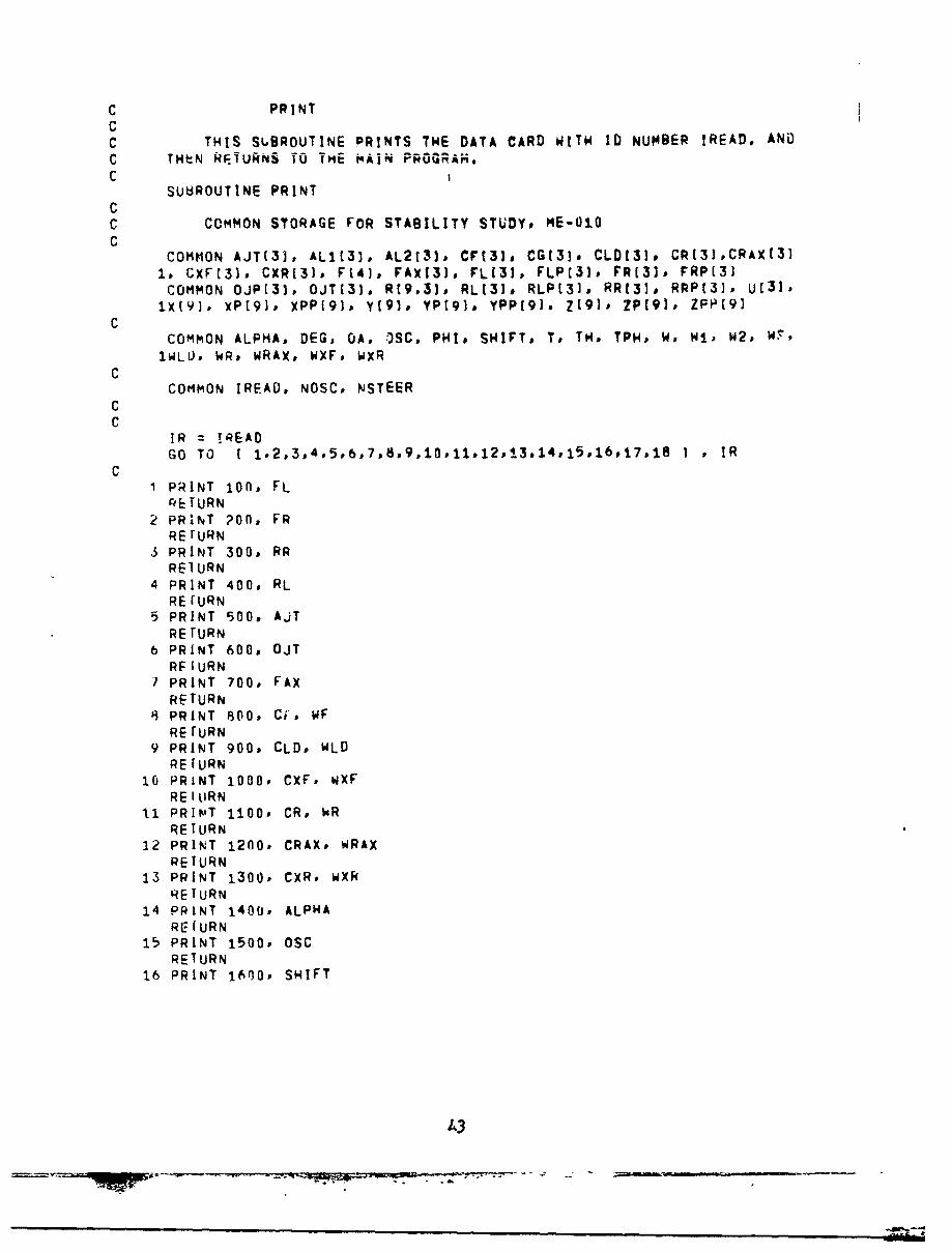
C PRINTCC THIS S8BROUTINE PRINTS THE DATA CARD WITW ID NUMBER IREAD, ANDC THeN kEURNS TO THE MAIN PROGRAH,C
SUHROUTINE PRINTCC COMMON STORAGE FOR STABILITY STUDY# ME-OiOC
COMMON AJT(3i, ALIE33, AL213), CF(3]. CGt3]. CLD(3), CRt3],CRAX(311, CXF(3], CXR[3), F14]. FAX13J, FL(31, FLP[3], FR131. FRP(3]
COMMON OJP(3], OJT(31, R(9.3)] RLt3]. RLP(3]. RRI3], RRP(31. U(3191x(9]. xP19]v XPP(91# y(910 YP(91. YPP[91] Z[9I. ZP(9]. ZPp[9]
CCOMMON ALPHA. DEG, GA, OSC, PHI. SHIFT. To TH, TPH* W, W1, W2, W7,
1WLU, WRv WRAX, WXF. WXRC
COMMON IREAD, NOSC, NSTEERCC
IR = TREADGO TO 1.2.3.4,5,6,7,8,9.10,11,12,'3.14,15,16,17,18 I • IR
C1 PRINT 100. FL
E TURN2 PRINT ?On, FR
RETURN3 PRINT 300, RR
REIURN4 PRINT 400, RL
RE fURN5 PRINT 500, AjT
RETURN6 PRINT 600, OJT
RFIURN7 PRINT 700, FAX
RETURN6 PRINT 800. Ci'. WF
RETURN9 PRINT 900, CLD, WLD
REFURN10 PRINT 1000o CXF, wXF
RE I RN11 PRINlT 1100, CR. WR
RETURN12 PRINT 1200, CRAX. WRAX
RETURN13 PRINT 1300, CXR, WXR
RETURN14 PRINT 1400, ALPHA
RE?(URN15 PRINT 1500. OSC
RETURN16 PRINT 1600. SHIFT
43

RE I RN17 POINT 17O00, NS1'EER
RE I URNI~PR!NT lannfl NOSCRETURN
lUfi FOnMATE1OX.1Ht,FIO.1. 1N,.F10.I14H,,FI0.I~1I4),5.X,3H3FL I?Uu r'ORMATt1OX,1I0t FI0.1,iH. .FtO.1,14, ,FIO.1HI ,5X,3HZFRI60i) FORt'AT(10XslH(,F1.0.1,1H,.F10.,I4,~,Fi0.1,1H3 ,5X,3HZRR I400 FCR,4AT(1oX,lI~r F1O.l,1H. .F1O.1,IH#,F Ol .~5X,3H:RL 150b FONHMATr1OX,2.Hr FI0.I,iN. ,FlO.l,1H,,FiO.1,1HI 5X,4HzAJTI600 FO'RMAT(I0X.1H( ,FIO.:,1.H. .F1O.1dNW ,FIO.l.1J4] 5X,4H:OJTI
bOO FOtRMAT(1OXIAHsUF10.1,e.4. FIO.±1H. b.FlO~l~lid 5X.3H:CFsF22'.l,4H SWF11
1LD I
lEF £
llUil FORMAT(1OX.1HEF1O.1,1N,,F1O.l,1H,,FIO.l,1'4] 5X.3t4ICRF2?.l,4H =WR
1]12(j(. FORFdATE~flx,lwtsFlO.l,1I~dF'10.1,1H,,Fio.1,I.H),5X,5H:CRAY,F2fl.1,6,
1WRAY 11301) FONMATt1OX.1HEFIo.i,1I.,,FIO.1,114,,FIo.l,1$].5X,4HzCXR,FPI1.l,5H 9W
lxRi14()f) FO(P.ATIF20.2,35H =ALPH.A (DE-GI zANGLE OF LEFT STEER 115011 FORMATfF2O.2,32H =OSC1DEG]:MAX OSCILLATION ANGLE I10011 FO~RMATIF2O.2,39m SwIFT, mEASURED FROM CENTER OF TREADl II./CU FORMAT11lO,52H =STEER TYPEjI*ART!CULATED#2zREAR WAGON*3=ACKERMA:NN!
lt,0u FORPiAT(I1O,59H =OSCILLATION TYPEt1:NO OSC,2zREAR AXLE OSC,3=MIDRAN1GF OSCI
CEN u
44
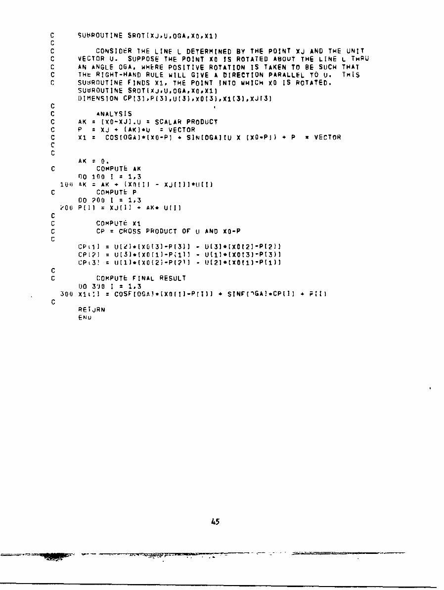
C SUt4POUTINE SROT[XJ,UOGA*XOXllCC CONSIDER THE LINE L DETERMINED BY THE POINT Xj AND THE UNITC VECTOR U. SUPPOSE THE POINT XO IS ROTATED ABOUT THE LINE L TmRUC AN ANGLE OGA, WHERE POSITIVE ROTATION IS TAKEN TO BE SUCH THATC THt RIGHT-HAND RULE WILL GIVE A DIRECTION PARALLEL TO U. TmiSC SUsROUTINE FINDS Xl, THE POINT INTO WHICH XO IS ROTATED.
SUbROUTINE SROTEXJU,OGAPXOPX1]DIMENSION CPt3I ,P[3),Ut3) xO(3] Xl32,XJr3]
CC ANALYSISC AK = (XO-XJJ.U % SCALAR PRODUCTC P = Xj + (AKI*U = VECTORC X1 = COS[OGAI*Ixo-P) * SIN(OGA]tU X (XO-Pj) * P a VECTORC
CAK = 0.
C COMPUTE AK00 100 1 1,3
100 AK = AK [ (XnIIJ - XjrIII*u(I)C COMPUTE P
DO ?00 I = 1,3?00 Pill = XJ[l] * AK* U[I]
CC COMPUTE X1C CP CROSS PRODUCT OF U AND XO-PC
CP1] U[2)*IXO(31-P(31] - Ut3]*[XO12]-P[211CP]L?= U(3]*[XO[1]-Pilll - U[1]*(XOt3]-P[3]]CPt3! kIJl]*(XO[2i-Pt2•1 - UJ[21*[XO[1]'P[1]
CC (:OMPUTE FINAL RESULT
1O 310 I = 1,3300 XiL1] COSF[OGA)*(XOrfl-PrI]] * SINF([GA!.CP[I] F*IJ
CRETJRNENU
45

C SUdROUTiNE OSNIA,B,C,DiL,P,PPICC G'3IVFN A TRIANGLE ARC ; ' A POINT P. WE WISH TO FIND THEC COORDINATES OF THE POINT P RELATIVE To A NEW AXIS SYST HAVIN'CC THe PROPERTIESC (1) THE NEW ORIGIN IS THE MIDPOINT OF SEG4rNT ASC (21 THE NEW Y-AXIS HAS THE DIRECTION OF THE VECTOR ABC [31 THE NEW Z-AXIS IS PERPENDICULAR TO PLANE ABCC (4) THE NEW X-COORDINATE OF C HAS THE SAME SIGN AS DEL, WHEREC f)EL EJUALS +1 OR -1.CC ANALYSIS. FIRST FIND THE DIRECTION COSINEC VECTORS OF THE NEW AXES RELATIVE TO THE OLD. THEN TRANSFORM P,C USING THE USUAL ORISOGONAL MATRIX OBTAINED FROM THE DIRECTIONC COSINE VECTORS.
SU"ROUTINE OSNIA,BC,DFLoP,PPIUI)MFNSION A[31°H[3],C[3],P[3],PP[3]°POI3],X[3],Y(3],Yl{3],Z[3),
1 ZL[3]
C FIND THE I DIRECTION COSINE VECTORSC
3o inn I = 1,3lull Yv i I.) ;[I 1 - All]
CC Z ( UC-Al CROSS Yi
71111 (C[21-A(2{]*Yi[3] - (C[31-A(3]1*YI[21Zltkl = lC~i]-A[3] ]eYI[I] - (;(I]-Atl]]*YI[31
ZiL31 (C(11-A(1)]*YI2 - (C[21-A(21I*Yir1!
C NORMALIZE Yi AND ZiP AND CHOOSE CORRECT DIRECTION FOR Z-AXIS.
AY = SQPTFL YILI]**2 * YVi21**2 * YV131**2 IA7 = SORTFI Z711)**2 * Zi123*'2 * ZI(3]**2 I
I0O 200 1 = 10YlIl = YI1i] / AY
eO1 7fl DEL=Z1(I] / A7CC CAI-CULTET x Y CROSS 7-C
Y[1] = Y[2J*7131 - Y[31'Z(2])(("I = Y[S3)*Zrl Y[1]*Z{3]X({ý = Y[il'Zf2] - Y[21]Z[1]
C TRANSFORM P TO GFT THE COORDINATES OF PP.C
110 300 I = 1,36011 potl] = n.
00 400 1 z 1,3Q = Pil] - .5"1 A[I]*BlII IPOtl] = Poll] + XII)*RPQi2 = P0121 + Y[i)*R
400 PQt3] = PQ[33 + Z[II.R
DO 500 1 = i13.OD Ppil] = PO~ll
SREfURN
•N4
I4
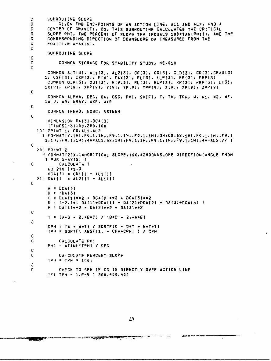
C SUBROUTINE SLOPEC GIVEN THE END-POINTS OF AN ACTION LINE, ALI. AND ALP, AND AC CENTER OF GRAVITY, CGp THIS SUBROUTINE CALCULATES THE CRITICALC SLOPE PHI, THE PERCENT OF SLOPE TPH (EQUALS IUU.TANlPMIjJj AND THEC CORRESPONDING DIRECTION OF DOWNSLOPE OA (MEASURED FROM THEc POSjTivE x-Ax!Sj.C
SUbROUTINE SLOPECC COMMON STORAGE FOR STABILITY STUDY, ME-010C
COMMON AJT(31, AL1[3), AL213i. CF133, CGC31, CLD131o CPR1],CRAXC3]1, L.XF[31, CXR(3], F141, FAX131, FLt3). FLP131. FR13)# FRP(31COMMON OJP(31* OJT!31, R(9,3JP RL(3]. RLPC33# RRt33, v(RP13), U(31#
ixIVI. (P191,0 XPP19)' Y(910 YP(91D YPP19],' Z19]0 2P19), ZpP19jC
COMMON ALPHA, DEG, OA, OSC, PHI* SHIFT, Tp TH, TPH# Wo Wip W2, WF,1WLIJ, WRs. WRAX, WXF, WXR
CCOMMON IREAD, NOSC, NSTEER
C1IUMENSION DA(31 D0CA[13IF LNOSC-3)100,200,100
ion PRINT Is CG#AL1,AL2I FOHMAT(/,IHUF9.iD1H,,F9.1,1'4,,F9.1,IHJ.3HsCG,6X~iH(,F9.1,1H, .F9.11,1'1,,19.l.1M],4H:AL1,5X,iH(,F9.1,1H,,F9.l1sHsF9.i,1HJ ,4W=AL?.// I
CŽrflIi PRINT 2
2 IOHMATi2OX.I4HCRITICAL SLOPE#16Xs42HDOWNSLOPE DIRECTIONEANGLE FROM1 PUS X-AXISJ I
C CALCULATE T0JO 210 1=1,.3OCA(I] = CG(I3 ALiIII
2110 DAMI = AL2(11 ALICI]C
A = DCA13JH=-DA(3]C=DCA[1I*.2 + DCA(P1.'2 + DCA(31*.2
fl = (-2.1*1 DA(1)*DCAf1] + DA[21*DCAC21 DA(3]oDCAjS]F =DAI11**2 - DA(21**2 * DAt3I'.2
CT z A*D -2.*B'Cl / [9.0 2.*A*E]
CCPH = (A B*Tl / SORTF(C *D*T * E*T*TlTPH = SQRTFl ABSF 11. - CPH*CPH] I / CPH
CC CALCULATE PHI
PHI = ATANF[TPH] / DEGCC CALCULATE PERCENT SLOPE
IPH = TPH * 100.
C CHECK TO SEE IF CG IS DIRECTLY OVER ACTION LINEIF[ TPH - 1.E-5 1 300,400#400
47

600U PRINT 3s PHI3 IORt4ATj/,F3G.2,21X,33HNONE-CG DIRECTLY OVER ACTION LINF*/,///I
RETURNC
400 XT ALiIlJ T* DA[11 CGrIIAy ~ 2 T~2 ~2
C CALCULATE DOWNSLOPE DIRECTIONC 4 QUAD ARCTAN ROUTINE
IFLXTJ 430,420,410'1U Q1A =0.
GO~ TO 44042'j OA =SIGNF[9n.#YT)
%;0 TO 4504~3I OA = SIcGNF[180,;YT11&ý1 OA =OA 4 ATANFIIYT/XT) / DEG450 CONT I NIE
C END OF~ 4 Q2UAD ARCTANC SEE IF THE VEHICLE HAS MIDRANGE OSCILLATION
IFLNOSC- - 31 500,600,500t)Uli PR!NT 4, PHI, TPH, OJAP T
4FONmAT[/,F2U.?,6H DJEG s*F9.2p4H PCTF21.2#4H DEG.F51.5,2H:T..////1
eI~fi RETURNtN 1)
48

C S;UHROUTINE IDSCC THIS SUBROUTINE VARIES THE DOWNSLOPE DIRECTION THROUGH 360
a- MR EE SO, AN FOR w A~ OCNS %PE OIEC!O tMASE COU% -11a v wLOV_%01C WISE FROM THE POSITIVE X-AxIS) TILTS THE GROUND PLANE IN4 THAT
uI I~rAtl I1J V ~III w IL %OUP4Ljl VI £UI F .1
C WHEEL-LOADS ARE PRINTED FOR FACH CRITICAL SLOPE,
SUBROUTINE MIDOSC.CCCC COMMON STORAGE FOR STARILITY STUDY, 9E-010
c COMMON AJT131, AL1C33, AL2131, CF(3]. CG(3), CLDf33s CR(31,CRAXI31
1, LXF(31, C;XR[3]. F141, FAXI3), FLI31, FLPC31, FR!31, FRP[3JCOMMON OJP13), UJTI31, R(9,31, RL13J, RLP13]. RR131o RRPI3)1 U(31,
1xtl)) XP(9). xPP19I, Y(911 YP(93, YPPf9I, Z(9)0 ?P191, ZPP[9]C
COlMON ALPM~', DEG, OA, OSC, PHI, SHIFT, To TH, TPH, W, WI, W2, WF,1WL-i;, WR* WkAx, WXFs wXR
CCOMP~ON IREAD, NOSO. NSTEER
CPRINT 50
50 F0HMAT(///sl0)X,103HFOLLOWING IS A TABLE GIVING SLOPES AT WHICH INS
1TAHILITY OCCURS FOR A VEHICLE WITH MIDRANGE OSCIL'-ATION.0/p1OXt271HTHETA Z UnWNSLOPE DIRECTION [MEASURED COUNTERCLOCKWISE FROM P05
3 X-AXIS],/,1OX,77HPHI a ANGLE THRU WHICH GROUND PLANE MUST 8E TI
4LTI:D FOR INSTABILITY TO OCCUR,/vIO)X,27HSLOPE =TANIPHII IN PERCENT5*1IjY,56HF[I) WHEEL LOAD AT TILT ANGLE PHI, AS INDICATED BELOW
CPRINT 51
t~l FORMAT[///' 44X ,4HLEFT ,5X, 5HRI GHT ,5X. 5HR IGHT, 6X #4HLEFT /, 43Y,15HtRONT,5X,5HFf4ONT,6X,4HREAR,bX,4HREAR,//,4X,5HTHETAD6Y,3HPH!,
6 X#
25HSLOPEhl5X,4HF[I],6X,4HFt2I.6X,4HFE31,6X,4HF(4I,/,4X,'5HtDEGJ.!:X,
35,HIDEG].5X,5H(PCT],14X,5HEL8S],5X,5H(LBS1,5X,5HtL8SJ.5X,5H(LBSJD4// 1
C TH DOWNSLOPE DIRECTION *DEG a PI / 180.C PHI SLOPE ANGLE , DEL aINITIAL INCREMENT IN PHIC
OEL = 5. * DEG07;1 .75*DEL
C VAFY TH FROM 0 TO 360 DEGREES0 E650 J=1,361
AJ = JTH (AJ - 1.1*DEG
C ROTATE GROUND PLANECALL RnTATI:
INITIALIZE PHIPHI = ELOPH =DEL
C TILT GROUND PLANE20(1l CALL TILT
49
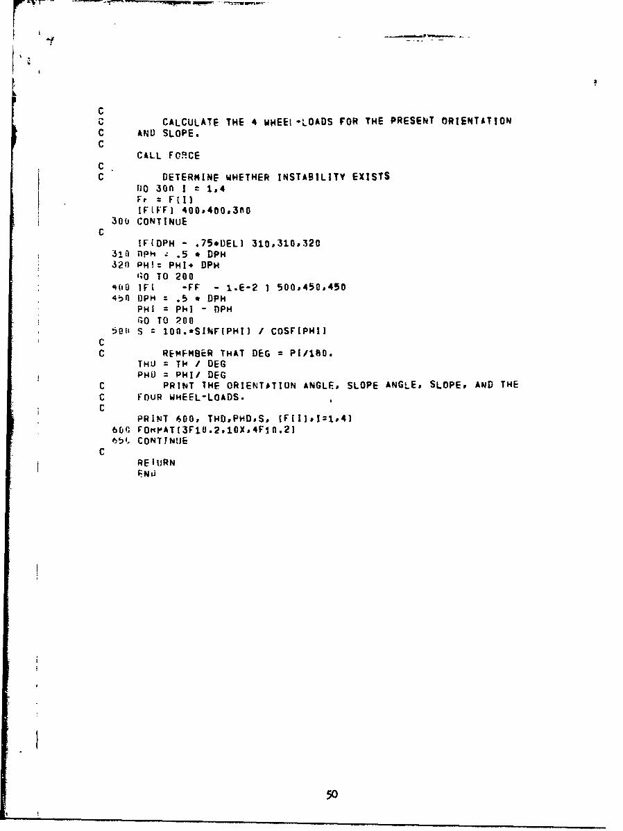
CC CALCULATE THE 4 WHEEt-LOADS FOR THE PRESENT ORIENTATIONC AND SLOPE.C
CALL FORCECC DETERMINE WHETHER INSTABILITY EXISTS
DO 30f I r 1,4Fr FillIFIIF] 400,400,300
30b CONTINUEC
IFIDPH - .75*DEL) 310,310,320310) IiPH z .5 * DPH320 PH!= PHI. DPH
'QO TO 200'.00 IFt "-FF - 1.E-2 1 500#450,4504b0 t)PH : .5 * DPH
PHI = PhI - TPH
GO TO 20050i0 S = 100.*SINF[PHIJ / COSFIPHI]
CC REMFMBER THAT DEG = PI/160.
THU = T14 I DEGPHO = PHI/ DEG
C PRINT THE ORIENTATION ANGLE, SLOPE ANGLE, SLOPE, AND THEC FOUR WHEEL-LOADS.C
PRINT 600, THD,PHD,S, [F[Il:1z,4166f, FOtPATI3F1O.2,10X,4F10.2]651, CONTINUE
CRE I tRNENI5
t5
I
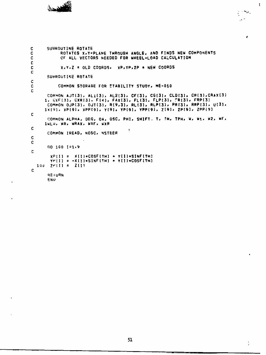
C SUUROUTINE ROTATEC ROTATES X#Y-PLANE THROUGH ANGLE, AND FINDS NEW COMPONENTSC OF ALL VECTORS NEEDED FOR WHEEL-LOAD CALCULATIONCC XPY.Z zOLD COORDS# XP#YP#ZP S NEW COORDSC
SUeRoUT1PNE ROTATECC COMMON STORAGE FOR EITABILITY STUOY. ME-010C
COMM4ON AJT[31, AL1(31, AL2131, CFI3), CG[3ID CLD(3)s CR(31,CRAX(331, L.XFf31, CXR131, Ft4j, FAX131, FL131. FLPt31, 7Rt31, FRP13JCOMMON OJP1315 OJT(31, R19,31, RL[31 RLP13I. PR(3.# RPP(31. U131-
1VE91, xPt91# xPP(91, Y(910 YP[91* YPP[9). Z19]. ZP19J. ZPPi9IC
COMMON ALPHA, DEG, OA, OSC, PHI, SHIFT, Ts TH. TPH. Wo Wit. W2# HF.1WLUP HRP WRAX, HXF. WXR
CCOMMON IREAD. NOSC. NSTEER
CC
00 100 1=1,9C
xP[I1 = X[IJ*COSF(T,41 * Y!I1'SINF(THIYPIII = -X(I]*SINFITHJ * vt~l]COSFiTHI1
Cr(E URNENU
51

C SUBROUTINE TILTC TILTS XP-AXIS THROUGH ANGLE PHI TOWARD ZP-AXIS,AND FINDS NEWC COMP:NENTS OF ALL VECTORS NEEDED FOR WHEEL-LOAD CALCULATIONSC IP.YPZP zOLD COORDS# XPPPYPP*ZPP xNEW COORDS
SUBROUTINE TILTCC COMMON STORAGE FOR STABILITY STUDY. ME-010C
COMMON AJT(3)p ALI(31. AL2131. CF(31. CG(31. CLDt3T1. CR'%31,CR4X[311. '.XF13), CXRI31. F(41, FAX131, rL(31* FLP[3)p FRI33, FRP(31COMMON OJPt3l, OJTI31, R19,31, RL(3)s RLP13lp RRf3I. RRP(31, u(31.
lX19), XPE9J. XPPI91, Y(9gJ, YPt910 YPPt9I, Z1910 ?P(91, ZPP(91
COMMON ALPHA, DEG, OA, OSC, PHI, SHIFT. To TM, TPH, W, Wit W2, WF.iWLD. HRP WRAX, WXF* HXR
COMMON IREAIJ, NOSC. NSTEERCC
DO 100 1=1,9C
xPv(Ilz XP(IIICOSFtPHI) + zPrII*SINF(PHIJvPPill x YPtI)
10d' 7PPiII1 x -XPlII*SINFtPHIl + ZP(II.COSF(PHI)C
RE tURN

C SUt4ROUTINE rIRCEC CALCULATIONI OF THE 4 wHEFL LGA03C
SUdROUTINE FORC:ECC COMMON STORAGE FOR STARILITY STUOYP ME-010C
COMMON AJT(31, AL1131, AL21319 CFI3). CGt33. CLD(3J. CP[31,CRAX(31
COMMON OJPi3). OJT131, R19,31* RL13I. RLP131j. RR*3]s RQP(3]p U13),
1X[91, xP'9], YPP(9I. Y1910 YP1912 YPP19J. Z(91, "2Pt9]. 7PP(9JC
COMMiON ALPHA, DEG, OA, OSC, PHI* SHIFT# To Two TOM, Wo Wi. W?. WF,1WLLJ. WRo WI(AX, WXF, WXR
CCOMMON IREAD. NOSC, KSTEER
CDIMENSION 0)141
C COMPUTIE COEFFICIENTS OF THF FIRST EQUATIONul = XPPlt9j*tYPPtlj.YPPtell YPP191*txppfll-xpptel]
'2=XPP[9J*[YPP(21-YPP[8IJ - YPP[91.IXPP[21.XPP1IOJO)CI: XPP19i'IY'PPl5]'-YPPIB] I - YPP!91,IXPP[15II'XPP(81 I
CC COMPUTE DETERMINANT OF COEFFICIENTSC
DlD = Dl'((XPPI3I-XPPT2JI*1YPP4143YPP(?fl - (XPPI41IXPP1211*1 1YPPI3]-YPP[2]1 I - D2*1 IXPPI3I-XPPE1I'*IYPPI4)-YPPtiI2 - (XPP(4I-XPPliII'(YPP(31-YPPtlII I
CC COMPUTE DENOMINIATOR DETERMINANTSC
i)111 = Wl.DCI~l IXPPT3I-XPP12II.*IYPPI4]-YPPI2)J - IXPP[41-XPPr7J1*1 VrPP[31-YPP[21] I - W*D2*1 IXPP(31-XPPE7II.IYPP(41)YPPf7)) -
2 IXPP[4I-XPP17] J*[YPP[31-YPP(711 IC
t)(2) W*Dl*t 1XPP[33-YPP1711*1YPP[1I-YPPt7Ii - XPP14]-XPP[7]1.
1 IYPP[31-YPPI7113- WI*DCIl [ XPPI3I-YPPI1II'(YPPt4I.YPP11iI -
2 1XPP[4)-XPP[II I'IYPP!33-YPPI1Il I
1)(3) = W*Dl* I IXPPt7I-XPP[21I*IYPPt4I-YPP[2JI - IXPP14]1XPP[213'I. IYPP71]-YF'P12II I - W*iD2* I iXPPi7I-XPPllIJ.EYPPE41-YPP11Pl -
2 tXDP414-XPP1III*[YPP[71-YPPt11] I + W1*DC1' I IXPP[2)-XPP[1)I*3 (YPP[41-YePtll] - IxPPt4]-XPP(E1IVIYPl?)2-YPPt1II I
C111=W.D1' IXPP13]-XPP[211*[YPPt7lIYPP[2II - IXPP(71-xPPr2lI.
1 (YPP[33-YPP!21] I - W*D2* I (XPPt3).XPPI1II*(YPPl7I-YPPj1])-2 LIXPP!73-XPP[I1I*rYPP?31IVPPI1II I - WI'DC1. I EXPP(12-XPP11Il*3 IYPPI3I-YfpI1I]l - (YPP131-XPP1Ijl*[YPP[12IYPP[IIJ I
CC CALCULATE THE FVUR wHEEL LOADSC
T)O1Q 0f 1=1.410V "f ii = DIll/DO
C
RE IURNFNIJ
53

C MMDOTYRSUHROUTINE MDOTVR
CC THIS SUaROUTT'iE COMPUTES CRITICAL SLOPES AND ORIENTATIONS FORC TURNOVER FOR A Vt- ICLE WITH MIDRANGE OSCILLATION. IT IS ASSUMEDC THAT THE VEHICLE IS INITIALLY SITTING ON A (HORIZONTALI PLANE INC A COMPLETELY OSCILLATED CONDITION WITH ONE OF THE 4 TIRES OFF THEC PLANE AND THE OTHER 3 ON THE PLANE. TURNOVER CALCULATIONS AREC MALF FOR EACH OF THE 4 TIRES OFF THE PLANE.CCC COMMON STORAGE FOR STARILITY STUDY, ME-010C
COMMON AJT(31, AL1[3], AL2131, CF!3], CG(3]o CLD(31] CR(3),CRAX[3]1. CXF[31, CXR13], Ff4), FAX[3], FLI31, FLP[31, FR(3)] FRP[3]
COMMON OJP[31, OJT13), R[9,31, RLI3]. RLP[3J, RRf3], RPPt3], U(Zl,IVx[), YP(9], XPP(9], VEY[, YP[9]0 YPPI9), Z[91, ZP[91, ZPP(91
C
COMMON ALPHA, DEG, 0A, OSC, PHI, SHIFT, T, TH, TPH, W, W1, W2, WF,1WLu, WR, WRAX, WXF, ýiXR
CCOMMON IREAD, NOSC. NSTEER
C"-IMENSION Cl(31]C2[31,CC113],CC2t3],FC[3]PRINT 1
1 FOkMATI1H1.20X,51HTURNOVER ASSUMING COMPLETE OSCILLATION HAS OCCURIREV I
CTAU = -OSC * DEG
C0)0 Ilo 1=1.3Cj[lJ 2 l*1
10U C21Il = R[6,I)C
00 7000 I : 1,4C
IOEL 2 (-1.]*.[I÷1]C
30 TO 11000,?000,3000,40001, ICC TURNOVER TO LEFT, WITH RIGHT FRONT TIRE OFF GROUNDC10011' CALL SROTIOJP,U,IAUFLP,FCI
CALL SROT[OJP.UTAUPCl,CC1)C
CALL OSN[RRP,RLPFCDELRLPAL1]CALL ORN[RRP,RLPFC,DEL,FC ,9A.2.]CALL OSN[RRPRLPFC.DELCCICC1]CALL OSN(RRP,RLP,FC.TELC2 .CC2;
CPRINT 2
SFOHMAT!///,lOX,54H[A] TURNOVER TO LEFT, WITH RIGHT FRONT TIRE OFF1GROUND .///]
C
54

Go TO) S6O0
C TUJRNOVER TO LEFT, WITH RIGHT REAR TIRE OFF GROUND
2D000 CALL SROTIO~jP,U.TAU*PLP*FCIVALL SROTIOjP,IUTAUPC2,CC2)
CALL OSP4(FRPFLP,FC,DEL,FC #ALI]
cALI OSN[ FRP,FLPFC,PEL,FLPpAL2)CALL ORN(FRP FLP,FC,:EL.LCl,CCI I
.2AL. Nt[FRPFLP,FC.PELPCC?#CCCI
CPRINT 3&5 Ok~MATf///p10X,53H[Hl TURNnVER TO LEFT, WITH RIGb4T REAR TIRE OFF Gi
Go To 9;ooo
C TURNOVER TO RIGHT,WITIH LEFT FRONT TIRE OFF GROUND
c3:6i~i: TA-) = -TAU
-ALL SPOT(0JP,1uTAUjfRPsFt~lCALl- SR0TIOJP.UvTAiJ,C.,'CC1 I
';ALI. OSN[ RPpRLiP,FC.DEL.HRPe ALl]
.ALI OqN[RHP,RLP.FC.PcLFC sAL2)
.A'-L osN[RP,RLP,FC.-ELD:C1DCC1Ic;ALL OSN[RHPvRLPFCD!1ELDC
2 *CC21
PkikNT 4a 7OtvdMATj///,1flX,54HtCI TURNOVER TO RIGHT, WiITH LEFT FRONT TIRE~ OFF
CqO TO 5(000
C TURNOVER TO RIGHT, WITH LEFT REAR TIRE OFF GROUND
4(IU~ts CAt~t SROTIDJP.U,TrAU,PRPSFC I
C~ALL. SPOTfOJP,U,TAU.C2 ICC2I
tCALL 0q14 IFkP,F LP,F C,VELI,FC. ALlfALL OsNIFwP,FLP,F C,DEL,FRPpAL2)
CALL osN~iFRP,FLP,FC.VEL,Cl.CCl I
~ALosNEFkP,FLPFC,PEL,CC2,CC2)
.-ORMATW///plnX,53HMD TURNOVER TO RIGHT, WITH LEFT REAR TIRE 3Fr G
C ComPUTh COMBINED CG FOR OSCILLATED VEHICLE
~ C CClij]*W1 a- CC;2[J]*W2 I W
cCALL SLOPE
cIFtPHI -I.E-41 70n0,5200,53200
55
WWI- ~- *--

~U'GO TO [5500,,56Q00550(0,56001*I
t)50(, IFitISTFER-2) fOO0.5 550, 6 00 0
.)55b OA =OA -ALPHA
lio TO ABOOOC5600 1FtNSTF4R-11 AOOO,5650.6000
CSi6tpl OA =OA + ALPHP
6uub~ PRINT 6# PII!,TPM.OAT
6 rOK~MAT[/.F2O.2,6H DEG =,F9.2,44 PCT,F212.24H DEGF5l.5,2H:T,////J
7001' CONTINUEC
QF f URN
56

"APPENDIX V
,s.... 'c. Ir f.OV T A1IIJI 7T VRI4TrT '!S
Following is the outp, t from three test ruis of the computer program.
The first test run is a stability study . a two-inch cube weighing ten
pounds. (The computer assumes the cube 1. a vehicle with the wheel loads
located at the botto four corners of the cube.)
The second and third test runs are stability studies of a fictitious
vehicle with rear axle oscillation. The second run uses the action line
method and the third run uses the wheel load method. In the third run, the
computer assumes that the vehicle has midrange oscillation with the
oscillation joint located at the center of the rear axle.
TEST RUN 1 STATIC STABILITY STUDY OF A CUBP
VEHICLE DATA
( 2.0, 1.0 0.03 BrL
t 2.0. '1.0. 0.03 'FRC 0.0, 1.0" 0.03 ORR
1 0.0, 1.0. 0.01 WRL
1 0.0. 0.08 0.01 sAJT
t 0.09 0.0. 0.03 sOJT
1 0.0, 0.0, 0.0) 8rAX
1 1.0. 0.0, 1.0) mCF 10.0 :WF
1 0.0, 0.0. 0.01 @CLD 0.0 :WLD
t 0.0. 0.0. 0.0) ECXF 0.0 ZWXF
C 0.0. 0.0. 0C.) SCR 0.0 NWR
C 0.0, 0.0. 0.0) @CRAX 0.0 :WRAX
t 0.0. 0.0, 0.03. aCXR 0.0 zWXR
0.00 zALFRA (DEGI ANGLE OF LFFT STEER
0.00 mOSC[DEGIsMAX OSCILLATION ANGLE
0.00 a SHIFT, MEASURED FROM CENTER OF TREAD
3 zSTEER TYPE(I#ARTICULATED,2REAR WAOONp3sACKERMANN)
1 9OSCILLATION TYPE118NO OSC,2-REAR AXLE OSC,3sMIDRANGE OSC)
57
-fm
40 a
C3.
w, C; C4 c4
CL
ata
.4 .4uiL
L.
isi
CD x
U) CK Cjc
vi a 3U
40 0 t
1..
cn U3 0--a j0
or C; --*
Lu~~U I- U
U0IL U 0C 4 C
LIJ Lus 0 LU CI
o C C C C;
LU 3 I~l C LU * L CCD
0. . 0. 0..4 0 * LU 4 D
LA atS M 0
o i* CK 0 Un U
C C D
CD C2C 2 :
C; C! CDLU
9- - 9-,
CDC
in C in C8

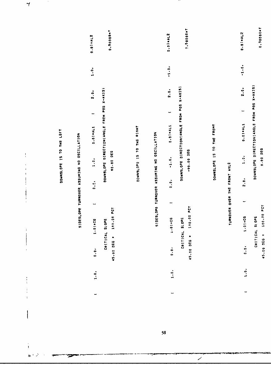
TEST RUN 2A - REAR AXLE OSCILLATION - USES ACTION LINE METHOD
VEHICLE DATA
1 100.0, 30.0 0.0) 'Lt 100.0, -30.0. 0.0 FIPR1 0.01 -30.0, 0.03 mRRt 0.0, 30.0. 0.0D IRL
50.0, 0.0, 30.03 sAITI nc,0 0.0. 30,0) *OJTI 100.0p 0.0. 30.01 vrAX( 60.0. 0.0. 40.0) vCF 5000.0 aUwt 150.0, 0.0. 50.0 'CLD 2000.0 vWLD
0.0, 0.0- 0.01 sCXF 0.0 awXr1 0.0, 0.01 0.03 meR 0.0 owR
0.0, 0.0. 30.03 'CRAX 1000.0 mWRAX0.01 0.0, 0.0D WCXR 0.0 awXR
0.00 *ALPHA (DEGI a ANOLE'OF t.FT STEER15.00 sOSC(DEGlmMAX OSCILLATION ANGLE0,00 a SHIFT, MEASURED FROM CENTER OF TREAD
I xSTEER TYPEC1mANTICULATED,#2REAR WAOONSm3ACKERMANN)2 'OSCILLATION TYPE(ImNO OSC#2sREAR AXLE OSC#3x:IDRANGE OSCI
59

N C N0 fu
- -A
a ~CDdo 0 do4
C C N
C, U).
C I CI IL
L) L
oU 0A (0
z. 0e 0. 0 A
z AU
W~4 a U)M .S.- .. - jzJ0.
4 (5 4 (5 4 a
C. .h .- B
4o U3 I
enC o C aL. - ae a
in V3 n 4
w us LU usA C) W * n* l0. CL IK CL In. * . *
c C~J 0 -. J 0 la 0 z1 n2V.~~ - -je - ne
2m co 2) .. u
o~A en 0cc0 0
ac un- ao - a- aCe
600

4.-j
40- U N
14 .4 .4)
* * u -
-.9L
4L I
a a a a * x* a * a
L& a
w LLJ aC a N
Z. 014Nl
z ; 0 D
(Il .*U C .
a ) 4 0 a. a.4
Mn 0 (fl 0. - mnCL on 0 0rrnC
f r . 10 .a
CL -j z
.4~~LL CDL - S .
04 LL 4 , 0I
aa.v IC
ew to C> 40
C3, UJi Ji Ui- a - - a - C)Il
C LI * 0 - -4
61a

?EST RUN 28 - MIDRANGE OSC AT REAR AXLE - USES WMEL LUAU ET;;0D
VEHICLE DATA
3 *OSCILLATION TVPE(ImNO OSC,?8REAR AXLE OSCS.MIDRANGE OSC)
1 65.7. 0.0. 42.91 a FRONT CG 7000.0 a FRONT WEIGHT
1 0.0. 0.0. 30.02 a REAR CC 1000.0 a REAR AEIGHT
t 75.0. 0.0. 41.21 a COOBIN@D CO 8000.0 a TOTI.L WEIGHT
FOLLOWING IS A TABLE GIVING SLOPES AT WHICH INSTABILITY OCCURS FOR A VEHICLE WITH MIDRANGE OSCILLATION.THETA 9 DOWNSLOPE DIRECTION I!iASUBED COUNTERCLOCKWISE FRO POS X-AXISIPHI 2 ANGLE TNRU WHICH GROUND PLANE OUST 9E TILTED FOR INSTABILITY TO OCCURSLOPE s TAN[PHI) I1 PERCENT Fill WHEEL LOAD AT TILT ANGLE PHI, AS INDICATED 9ELOW
LEFT RIGHT RIGHT LEFTFRONT FRONT REAR REAR
THETA PHI SLOPE rrii F12) F(31 F14](DEG) [DEG) (PCT) (LBOS] LBS) (LOS] (CBS]
0.00 31.22 60.61 4000.01 4000.01 -0.01 -0.011.00 31.22 60.62 4058.19 3941.82 -0.00 -0.002.00 31.23 60.64 4116.41 3683.61 -0.01 -0.013.00 31.25 60.69 4174.70 3825.31 -0.00 -0.004.00 31.28 60.75 4233.10 3766.91 -0.01 -0.015.00 31.32 60.84 4291.64 3708.37 -0.01 -0.016.00 31.36 60.94 4350.36 3649.66 -0.01 -0.017.00 31.41 61.06 4409.30 3590.72 -0.01 -0.018.00 31.47 61.20 4468.49 3531.94 -0.01 -0.019.00 31.53 61.36 4527.96 3472.05 00.01 -0.01
10.00 31.61 61.54 4587.76 3412.24 -0.00 -0.0011.00 31.69 61.74 4647.95 3352.07 -0.01 -0.0112.00 31.78 61.96 4708.53 3291.48 -0.01 -0.0113.00 31.88 62.20 4769.57 3230.44 -0.01 -0.0114.00 31.99 62.46 4831.11 3168.91 6.01 -0.0115.00 32.11 62.74 4893.18 3106.84 -0.01 -0.0116.00 32.23 63.05 4955.82 3044.18 -8.00 -0.0017.00 32.36 63.38 5019.12 2980.90 -0.01 -0.0118.00 32.51 63.72 5083.07 2916.93 -0.00 -0.0019,00 32.66 64.10 5147.77 2852.24 -0.00 -0.0120.00 32.82 64.50 5213.25 2786.76 -0.01 -0.0121.00 32.99 64.92 5279.57 2720.45 -0.01 -0.01
62
-7

22.00 33.17 65.37 5346.77 2653.24 -0.00 -0.0123.00 33.36 65.84 5414.95 2985.08 -0.01 -0.0124.00 33.56 66.34 5484.11 2515.90 -0.00 -0.0125.00 33.77 66.87 5554.38 2445.64 -0.00 -0.0126.00 33.99 67.43 5625.81 2374.21 -0.01 -0.0227.00 34.22 68.02 5698.44 2301.57 -0.00 -0.0128.00 34.47 68.64 5772.36 2227.64 -0.00 -0.0029.00 34.72 69.29 5847.71 2152.30 -0.00 -0.013P.00 34.99 69.98 5924.54 2075.48 -0.01 -0.0231.00 35.26 70.71 6002.89 1#97.12 -0.00 -0.0132.00 35.55 71.47 6082.91 1917.10 0'.00 -0.0,33.00 35.85 72.27 6164.74 1535.29 -8.01 -0.0234.00 36.17 73.10 6248.39 1751.63 -0.00 -0.8135.00 36.50 73.99 6334.05 1665.96 -0.00 -0.0136.00 36.84 74.91 6421.85 1978.17 -0.01 -0.0237.00 37.19 75.89 6511.91 1488.12 -0.01 -0.0238.00 37.56 76.91 6604.30 1395.70 -0.00 -0.0139.00 37.95 77.99 6699.31 13t-.71 -0,00 -0.0140.00 38.35 79.12 6797.02 1202.99 -0.00 -0.0141.00 38.77 80.30 6897.63 1t02.37 -0.00 -0.0042.00 39.20 81.55 7001.37 998.64 -0.00 -0.0143.00 39.65 82.87 7108.46 891.57 04-01 -0.0344.00 40.12 94.25 7219.04 780.99 -6.01 -0.0245.00 40.60 85.71 7333.36 666.65 -0.00 -0.0146.00 41.10 87.25 7451.80 548.21 -0.00 -0.0147.00 41.63 88.87 7574.67 425.37 -0.01 -0.0348.00 42.17 90.58 7702.17 297.88 -8.01 -0.0449.00 42.73 92.38 7834.66 165.38 -0.01 -0.0350.00 43,32 94.29 7972.62 27.42 -0.01 -0.0351.00 43,04 93.39 7939.45 -0.00 C.30 52.2552.00 42.57 91.87 7866.46 -0.01 18.44 115.1253.00 42.12 90.42 7795.71 -0.01 28.39 175.9154.00 41.68 89.04 7727.07 -0.00 38.17 234.7755.00 41.26 87.72 7660.43 -0.00 47.78 291.7956.00 40.85 86.47 7595.66 -0.00 57.24 347.1057.00 40.46 85.27 7532.65 -0.00 66.56 400.8058.00 40.08 84.13 7471.30 -0.01 75.74 452.9759.00 39.71 83.05 7411.51 -0.00 84.79 503.7160.00 39.36 82.01 7353.18 -0.00 93.71 553.1164.00 39.02 81.02 7296.26 -0.01 102.53 601.2362.00 38,s9 80.08 7240.62 -0.00 111.23 648.1563,00 38.37 79.18 7186.23 -0.01 119.83 693,9464.00 38.07 78.32 7133.01 -0.00 128.34 738.6665,00 37.78 77.50 7080.88 -0.00 136.76 782.3666.00 37.50 76.72 7029.79 -0.00 145.10 825.1167.00 37.23 75.98 6979.68 -0.00 153.36 866.9668.00 36.97 75.27 6930.50 -0.00 161.55 907.9569.00 36,72 74.60 6882.20 -0.00 169.67 948.1370.00 36.49 73.96 6834.72 -0.00 177.73 987.5571.00 36.26 73.35 6788.02 -0.00 185.73 1026.2572.00 36.04 72.77 6742.05 -0.00 193.69 1064.2673.00 35.84 72.22 6696.78 -0.00 201.60 1101.6374.00 35.64 71.70 6652.15 -0.00 209.46 1138.3975.00 35.45 71.20 6608.15 -0.00 217.29 1174.5676.00 35.27 70.74 6564.72 -0.00 225.09 1210.1977.00 35.11 70.30 6521.83 -0.00 232.86 1245.31
63

78:00 a4.Qf5 9.s8 6479.46 -0.0i 240 .61 1279.94
79.00 34.79 69.49 6437.55 Co.0 24e.33 j314.12
AAf-n 14.Al 69.12 6396.10 -0.00 256.05 1347.A6
81.0,0 34.52 68.78 6355.06 o0.0-i 26.75 i36i.i9
82.A0 34.39 68.46 6314.41 -0.01 271.49 1414.14
83.40 34.28 68.16 6274.13 -0.01 279.14 1446.74
84.-0 34.17 67.88 6234.17 -0.01 286.84 1479.00
85.00 34.07 67.63 6194.52 -0.00 294.55 1510.94
86.00 33.98 67.40 6155.15 -0-01 302.26 1942.59
87.00 33.89 67.18 6116.03 -0.00 310.00 1973.97
8s.6 33.82 66.99 6077.16 -0.01 317.75 1605.10
89.00 33.75 66.82 6038.49 -0.00 325.53 1635.99
90.00 33.69 66.67 6000.00 -0.00 333.33 1666.67
91.00 33.64 66.53 5961.68 -0.00 341.17 1697.15
92.00 33.59 66.42 5923.51 -0.00 349.05 1727.45
93.00 33.56 66.33 5885.45 -0.01 356.97 1757.59
94.00 33.53 66.25 5847.49 -0.01 364.93 1787.5&
95.00 33.50 66.20 5809.61 -0.01 372.95 1817.44
96.00 33.49 66.16 5771.78 -0.00 361.03 1847.19
97.00 33.48 66.14 5734.00 -0.01 389.17 1876.84
98.00 33.48 66.15 5696.21 -0.00 397.36 1906.41
99.00 33.49 66.17 5658.44 -0.01 409.66 1935.92
100.00 33.51 66.21 5620.62 -0.00 414.02 1965.37
101.00 33.53 66.26 5582.76 -0.01 422.46 1994.79
102.00 33.56 66.34 5544.83 -0.00 430.99 2024.1G
103.00 33.60 66.44 5506.81 -$.00 439.62 2053.57
104.00 33.64 66.55 5468.69 -0.01 448.35 2082.96
105.00 33.70 66.69 5430.43 -o00 457.20 2112.38
106.00 33.76 66.84 5392.02 -0.01 466.15 2141.84
107.00 33.83 67.01 5353.43 -0.00 475.24 2171.34
108.00 33.90 67.21 5314.64 -0.01 484.45 2200.91
109.00 33.99' 67.42 5275.64 -0.01 493.80 2230.57
110.00 34.08 67.66 5236.39 -0.01 503.30 2260.31
111.00 34.18 67.91 5196.87 -0.00 51t.96 2290.17
112.00 34.29 68.19 5157.07 -0.00 922.78 2320.15
113.00 34.41 66.48 5116.95 -0.00 532.76 2350.27
114.00 34.53 65.80 5076.50 -0.01 542.96 2380.54
115.00 34.66 69.14 5035.68 -0.00 553.34 2410.98
116.00 34.80 69.51 4994.47 -0.00 56- 93 2441.61
117.00 34.95 69.90 4952.85 -0.01 576./1 2472.43
118.00 35.11 70.31 4910.77 -0.00 585.76 2503.47
119.00 35.28 70.74 4868.23 -0.01 597.04 2534.74
120.00 35.45 71.20 4825-.18 -0.00 606.58 2566.25
121.00 35.64 71.69 4781.60 -0.00 620.39 2598.02
122-.00 35.83 72.20 4737.45 -0.00 632.49 2630.07
123.00 36.03 72.74 4692.70 -0.00 644.89 2662.41
124.-00 36.24 73.30 4647.32 -0.00 657.62 2695.06
125.00 36.46 73.90 4601.27 -0.00 670.69 2728.04
126.00 36.69 74.52 4554.53 -0.01 664o12 2761.36
127.00 36.93 75.18 4507.03 *0.00 697.94 2795.03
128.00 37.18 75.86 4458.76 -0.00 712.16 2829.08
129.00 37.44 76.58 4409.66 -0.00 726.82 2863.52
130.00 37.71 77.33 4359.70 -0.00 74t.94 2898.37
13i.00 37.99 71.11 4308.83 -0.00 797.54 2933.63
132.00 38.29 7a.94 4257.00 -0.00 773.67 2969.34
133.00 38.59 79.79 4204.17 -0.00 790.34 3005.50
£34.00 38.90 80.69 4150.28 -0.00 607.60 3542.12
641- 7

135.00 39.22 8i.63 4095.29 -0.00 825.49 3079.22A". ,, .n lVi 844.03 3118683
13s.00 39,56 62.60 -u--. ..
137.00 39.90 83.62 3981.76 -0.01 863.29 3U54.93138.00 40.26 84.69 ,%. ..a.A.. .. 93.55
139.00 40.63 65.80 3863.17 0.01. 904.13 3232.70
140.00 41.0i 86.96 3801.81 -0.01 925.82 3272.38
141.5C 41.40 88.16 3738.98 -0.00 948.44 3312.58
142.00 41.80 89.42 3674.64 -0.01 971.04 3353.33
143:00 42.22 90.73 3608.70 -0.01 996.71 3394.60
144.00 42.65 92.10 3541.10 -0.00 1022.51 3436.39
146.00 43.08 93.53 3471.78 -0.01 1049.53 3476.70
146.0: 43.53 95.01 3400.65 -0.00 1077.86 3521.49
147.00 44.00 96.56 3327.66 -0.00 1107.60 3564.75
14s8.00 44.47 98.17 3252.72 -0.01 1138.85 3608.44
149.00 44.96 99.84 3175.78 -0.00 1171.73 3652.50
150.00 45.45 i01.59 3096.76 -0.00 1206.35 3696.89
151.00 45.96 103.40 3015.60 -0.01 1242.87 3741.54
152.00 46.48 105.29 2932.24 -0.00 1281.41 3786.35
153.00 47.00 107.25 2846.63 -0.01 1322.13 3831.24
154.00 47.54 109.28 2758.73 -0.01 1365.21 3876.06
155.00 48.08 111.39 2668.49 -0.01 1410.82 3920.69
156.00 48.64 Uj3.56 2575.90 -0.00 1459.16 3964.94
157.00 49.20 1.5.85 2480.95 -0.01 1510.42 4008.63
158.00 49.77 118.19 2383.65 -0.00 1564.83 4051.51
159.00 50.34 120.62 2284.02 -0.01 1622.62 4093.37
160.00 50.92 !23.12 2182.13 -0.00 1644.02 4033.86
161.00 51.50 125.69 2078.05 -0.00 1749.28 4172.67
162.00 52.09 118.35 1971.90 -0.00 1818.65 4209.46
163.00 52.66 1j8.07 1563.81 -0.00 1891.40 4243.79
164300 53.24 133.85 1753.97 -0.00 1970.78 4275.25
165.00 53.81 136.70 1642.58 -0-01 2094.06 4303.37
166.00 54.39 139.60 1529.89 -0.01 2142.47 4327.65
167,00 54.95 142.56 1416.20 -0.00 2236.24 4347.56
168.00 55.51 145.55 1301.79 -0.01 2335.61 4362.61169*00 56.06 148.58 1187.01 -0.00 2440.75 4372.24
170.00 56.60 151.63 1072.23 -0.00 2551.34 4375.94
171.00 57.62_ 151670 957.79 -0.00 2665.99 4373.22
172,00 57.63 157.76 844.08 -0.00 2792.31 4363.61
173200 58.13 160.85 731.47 -0.00 2921.84 4Z46.68
174.00 58.61 163.92 620-31 -0.00 3057.62 4322.07
175400 59.06 166.97 510.93 -0.00 3199.61 4289.46
176.00 59.53 17060. 403.62 -0.00 3347.78 4248.61
177.00 59.97 173.00 298.67 -0.01 3502.02 4199.32
178.00 60.39 175.98 196.29 -0.01 3662.22 4J41.49
179.00 60.30 175.92 96.69 -0.01 3828.27 4075.05
180000 61.19 181.82 .0.01, -0.01 4000.01 4000.01
161.00 60.80 178.92 -0.01 96.69 4075.05 3828.27
182.00 60.39 175.98 -0.01 196.29 414t.49 3662.22
183.00 59.97 173.00 -0.01 298.67 4199.32 3502.02
184,00 59.53 170.00 -0.00 403-62 4248.61 3347.78
185.00 59.08 166.97 -0.00 510.93 4289.46 3199.61
186.00 58.61 163.92 -0.00 620-31 4322.07 3057.62
187,00 58.13 160.85 -0.00 731.47 4346.68 2921.84
188000 57.63 07.78 -0.00 844.58 4363.61 2792.31
189800 57.12 154.70 -0.00 957.79 4373.22 2668.99
190.00 56.60 151.63 -0.00 1072.23 4375.94 2551.84
191.100 56.06 148.58 -0.00 1187.01 4372.24 2440.75
65
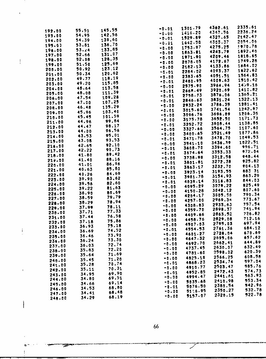
192,00 55.51 145.55 -0.01 1301.79 4362.61 2335.61
193.00 54.95 142.56 q . ....... ......194.00 54.39 139.60 "0.01 1529.89 4327.65 2142.47
194 .00 53 .81 136 .70 "6 .6i i6 2 AT . . ......
196.00 53.84 133.85 -0.00 1753.97 4279.25 i970.78
197.00 52.66 131.07 -0.00 1863.01 4243.79 1092.40
197.00 52.06 128.37 -0.00 1971.90 4209.46 1i18.65
199000 51.50 125.69 -0.00 2078.605 4172.67 1749.28
200.00 50.92 123512 -0.00 2W82.13 4133.86 1484.02
20t.00 50.34 123.62 -C.01 2284.02 4093.37 1622.62
202.00 49077 128.19 -0.00 2383.65 4051.51 1564.03
203.00 49.20 115.85 -0.01 2480.95 4008.63 1510.42
204.00 48.64 113.58 -0.00 2575.90 3964.94 14-.9,16
204.00 48.08 111.39 -0.01 266A-49 3920.69 1410.82
206.00 47.54 109.28 -0.01 2758.13 3876.06 ±365.21
207.00 47.00 107.25 -0.01 2846.63 3831.24 1322.13
208.00 46.48 135.29 -0.00 2932.24 3786.35 1281.41
209.00 45.96 103.40 -0.01 3015.60 3741.54 1242.87
210.00 45.45 101.59 -0.00 3096.76 3696.89 1206.35
211.00 44.96 99.84 -0.00 3U75-78 3652.50 1171.73
212.00 44.47 98.17 -0.01 3252.72 3600.44 1138.85
213.00 44.00 96.56 -0.00 3327.66 3564.75 1107.60
214.00 43.53 95.01 -0.00 3400.65 3521.49 1077.86
215.00 43.08 93.53 -0.01 3471.78 3478.70 1049.53
216.00 42.65 92.10 -0.00 3541.10 3436.39 1022.51
217.00 42.22 90.73 -0.01 3608.70 3394.60 996.71
218.00 41.80 89.42 -0.01 3674.64 3353.33 172.04
214.00 41.40 88.16 -0.00 3738-98 3312.58 948.44
220.00 41.01 86.96 -0.01 3001.81 3272.38 925.02
221.00 40.63 85.80 -0.01 3863.17 3232.70 904.13
222.00 40.26 84.69 -0.00 3923.14 3193.55 083 31
223.00 39.90 83.62 -0.01 3981.78 3154.93 863.29
224.00 39.56 82.60 -0.01 4039-14 3116.83 844.03
225.00 39.22 81.63 -0.00 4095.29 3079.22 025.49
226.00 38.90 80.69 -0.00 4150.28 3042.12 807.60
227.00 38.59 79.79 -0.00 4204.17 3005.36 790.34
228.00 38.29 78.94 -0.00 4257-00 2969.34 773.67
229.00 37.99 70.11 '0.00 4308.83 2933.63 757.54
230.00 37.71 77.33 -0.00 4359.70 2890.!7 741.94
231.00 37.44 76.50 -0.00 4409-66 2863.52 726.82
232.00 37.18 75.86 -0.00 4458.76 2829.08 712.16
233.00 36.93 75.18 -0.00 4907.03 2795.03 697.94
234.00 36.69 74.52 -0.01 4954.53 2761.36 684.12
235.00 36.46 73.90 -0.00 4601.27 2720.04 670.69
236.00 36.24 73.30 -0.00 4647.32 2695.06 657.62
237.00 36.03 72.74 -0.00 4692.70 2662.41 644.69
238.00 35.83 72.20 -0.00 4737.45 2630.07 632.49
239.00 35.64 71.69 -0.00 4781.60 2598.02 620.39
240.00 35.45 71.20 -0.00 4825.18 2566.25 608.58
241.00 35.28 70.74 -0.01 4868.23 2534.74 597.04
242.00 35.11 70.31 -0.00 4910.77 2503.47 585.76
243.00 34.95 69.90 -0.01 4952.85 2472.43 574.73
244.00 34.80 69.51 -0.00 4994.47 2441.61 563.93
245.00 34.66 69.14 -0.00 5035.68 2410.98 553.34
246.00 34.53 68.80 -0.01 5076.50 2380.54 542.96
247.00 34.41 66.46 "0.00 5Wi6.95 2350.27 532.78
248.00 34.29 68.19 -0.00 5157.07 2320.15 522.78
66

249.00 34.18 67.91 -0.00 5196.87 2290.17 912.96250.00 34.08 67.66 -0.01 5236.39 2260.31 503.30251.00 33.99 67.42 -0-01 5275.64 2230.57 493.80252.00 33.90 67.21 -6.01 9314.64 2200.91 484.45253,00 33.83 67.01 -0.00 5353.43 2171.34 47r.24254.00 33.76 66.84 -0.01 5392.02 2141.84 486.15259.00 33.70 66.69 aOIO 5430.43 2112.38 457.20256.00 33.64 66.55 '0.01 5468.69 2082.96 448.35257.00 33.60 66.44 -0.00 5906.81 2053.57 439.62258.00 33.56 66.34 -0.00 5544.83 2024.18 430.99259.00 33.53 66.26 -0.01 5382.76 1994.79 422.46260.00 33.51 66.21 -0.00 5620.62 1969.37 414.02261.00 33.49 66.17 -0,01 5658.44 1935.92 405.66262.00 33.48 66.15 -0.00 9696.21 1906.41 397.38263.00 33.48 66.14 -0.01 9734.00 1876.84 389.17264,00 33.49 66.16 -0.00 5771.78 1847.19 381.03265.00 33.50 66.20 -0.01 5809.61 1817.44 ,72.95266.00 33.53 66.25 -0.01 5847.49 1787.58 364.93267.00 33.56 66.33 -0.01 5885.45 1797.59 356.97268.00 33.59 66.42 00.00 9923.-1 1727.45 349.05269.00 33.64 66.53 -0.00 5961.68 1697.15 341.17270.00 33.69 66.67 -0.00 6000.00 1666.67 333.33271.00 33.75 66.82 "-.00 6038.49 1635.99 325.53272.00 33.82 66.99 -0.01 6077.16 1605.10 317.75273.0 33.89 67.18 -0.00 6116.03 1573.97 310.00274.00 33.98 67.40 -0.01 6055.15 1542.59 302.26275.00 34.07 67.63 -0.00 6194.52 1510.94 294.55276.00 34.17 67.88 -0.01 6234.17 1479.00 286.84277.00 34.28 68.16 -0.01 6274.13 1446.74 279.14278.00 34.39 68.46 -0.01 6314.41 1414.14 271.45279.00 34.52 68.78 -0.00 6355.06 1381.19 263.75280.00 34.65 69.12 -0.00 6396.10 1347.86 256.05281.00 34.79 69.49 -0.00 6437.55 1314.12 248.33282.00 34.95 69.88 -0.01 6479.46 1279.94 240.61283,00 35.11 70.30 -0.00 6521.83 1249.31 232.86284.00 35.27 70.74 -0.00 6564.72 1210.19 225.09285.00 35.45 71.20 -0.00 6608.15 1174.56 217.29286.00 35.64 71.70 -0.00 6652.15 1138.39 209.46287.00 35.84 72.22 -0.00 6696.78 1101.63 201.60288,00 36.04 72.77 -0.00 6742.05 1064.26 193.69289.00 36.26 73.35 -0.00 6788.02 1026.25 185.73290.00 36.49 73.96 -0.00 6834.72 987.55 177.73291.00 36.72 74.60 -0.00 6882.20 948.13 169.67292.00 36.97 75.27 -0.00 6930.50 907.95 161.55293.00 37.23 75.98 -0.00 6979.68 866.96 153.36294.00 37.50 76.72 -0.00 7029.79 825.11 145.10295.00 37.78 77.50 -0.00 7080.88 782.36 136.76296.00 38.07 78.32 -0.00 7133.00 738.66 128.34297.00 38.37 79.18 -0.01 7186.23 693.94 119.83298.00 38.69 80.08 -0.00 7240.62 648.15 111.23299.00 39.02 81.02 -0.01 7296.26 601.23 102.53300.00 39.36 82.01 -0.00 7353.18 553.11 93.71301.00 39.71 83.05 -0.00 7411.51 503.71 84.79702.00 40.08 84.13 -0.01 7471.30 452.97 75.74303.QQ 40.46 85.27 -0.00 7532,65 400.00 66.56
67

304.00 40.85 86.47 -0.00 7595.66 347.10 57.24
305.00 41.26 87.72 -0.00 710.3 4V v f I v306.00 41,68 89.04 -0.00 7727.07 234.77 38.17
307.00 42.12 90.42 -j.0i 7795.71 1& .97 28.39
308.00 42.57 91.87 -t.01 7866.46 115.12 18.44
309.00 43.04 93.39 -0.00 7939.45 52.25 8.30
311.00 43.32 94.29 27.48 7972.53 -0.01 -0.00
3ii,00 42.73 92.38 165.43 7834.57 -0.00 -0.00
312.00 42.17 90.57 297.95 7702.06 -0.00 -0.00
313.00 41.63 88.87 425.43 7574.-58 -0.01 -0.00
314.00 41.10 87.25 549.21 7451.80 -0.01 -0.00
315.00 40.60 85.71 666.65 7333.36 -0.01 -n.00
316.00 4G.12 84.25 781.02 7218.98 -0.01 -0.00317,00 39.65 82.87 891.60 7108.41 -0.01 -0.00318.00 39.20 81.55 998.64 7001.37 -0.01 -0.00319.00 38.77 80.30 1102.37 6897.63 -0.00 -0.00
320.00 38.35 79.12 1202.99 6797.02 -0.01 -0.00321.00 37.95 77.99 1300.71 6699.31 -0.01 -0.00322.00 37.56 76.91 1395.70 6604.30 -0.01 -0.00
323.00 37.19 75.89 1488.14 6511.87 -0.01 -0.00
324.00 36.84 74.91 1578.19 6421.81 -0.00 -0.00
325.00 36.50 73.99 1665.97 6334.03 -0.00 -0.00326.00 36.17 73.19 1751.63 6248.39 -0.01 -0.00
321.00 35.85 72.26 1835.31 6164.70 -0.00 -0.00328.;. 35.55 71.47 1917.10 6082.91 -0.01 -0.00329.00 35.26 70.71 1997.13 6002.88 -0.00 -0.00
330.00 34.99 69.98 2075.50 5924.50 -0.00 -0.00331.00 34.72 69.29 2152.30 5847.71 -0.01 -0.00332.00 34.47 68.64 2227.64 5772.36 -0.00 -0.00
333.00 34.22 68.02 2301.57 5f98.44 -0.01 -0.00334.00 33.99 67.43 2374.22 5625.78 -0.00 -0.00335.00 33.77 66.87 2445.64 5554.38 -0.01 -0.00336.00 33.56 66.34 2515.90 5484.11 -0.01 -0.00
337.00 33.36 65.84 2585.08 5414.93 -0.01 -0.00338.00 33.17 65.37 2653.24 5346.77 -0.01 -0.00
339.00 32.99 64.92 1720.45 5279.56 -0.00 -0.00340.00 32.82 64.50 2786.76 5213.25 -0.01 -0.01341.00 32.66 64.10 2852.24 5147.77 -0.01 -0.00342.00 32.51 63.72 2916.93 5083-07 -0.00 -0.00
343.00 32.36 63.38 2980.90 5019.11 -0.00 -0.00344.00 32.23 63.05 3044.18 4955.82 -0.00 -0.00
345.00 32.11 62.74 3106.84 4893.18 -0.01 -0.01
346,00 31.99 62.46 3168.91 4831.10 -0.00 -0.00347.00 31.88 62.20 3230.44 4769.57 -0.01 -0.01341.00 31.78 61.96 3291.48 4708.53 -0501 -0.%1349.00 31.69 61.74 3352.07 4647.94 -0.00 -0.,3)350.00 31.61 61.54 3412.24 4587.76 -0.00 -0.00351.00 31.53 61.36 3472.05 4527.96 -0.01 -0.01
352.00 31.47 61.20 3531.53 4468.48 -0.00 -0.00353.00 31.41 61.06 3590.72 4409.29 -0.00 -0.00354.00 31.36 60.94 3649.65 4350.35 -0.00 -0.00
355.00 31.32 60.84 3708.37 4291.64 -0.01 -0.01356.00 31.28 60.75 3766.91 4233.10 -0.01 -0.01
357.00 31.25 60.69 3825.31 4174.70 -0.00 -0.00358.00 31.23 60.64 3883.60 4116.41 -0.00 -n.00359.00 31.22 60.62 3941.82 4058.19 -0.00 -.1,00360.00 31.22 60.61 4000.01 4000.01 -0.01 -0.01
68
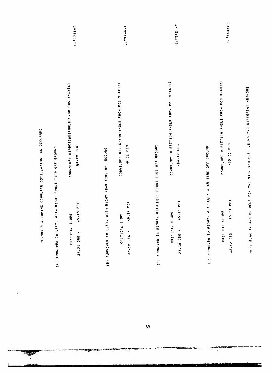
I--
-V' )
4 CL
a S 3
an an w0 0 2.
t 0 A-
Lt 0
L)uLU 0-f
0 0 4U 0 U 0u nL
x 0 0r 0lL) C
0 - 0 aI.-4
U N a43, 1 Lfl
0j LU 31 U
L L
C.I 0 - -0
C~(. LU LU
, CC . L
0 L) 0. w ] *C0
3- I.% W. LL a.. r4j CD.j ~ .
M w. ui Cý G. a.. (V 4
L. 0 2. 2 c 2
8.l 0 -C 0 .0LUCU
-C - V I .
> L)
LU 2. 4 04
U ~ L C L L
z 0.
anA 0Dn in * i C i
4 * 4- 4 - - a- ~ 69
a- an a-Nkomo an-

•UnrJlas. i edS-,,rity Classification
DOCUMENT CONTROL DATA- R&D(security claasuicaficaon of tit)e body of uabstract end indeiting annotation mus• br artiro, ©, c.;•.. :=i: :.t
I ORIGINATIN G ACTI'I1Y (Corporate author) 2a REPORT SECt. RITY C .ASSIFICATION
Unlcas LIedU. S. Army Natick Laboratories 2b GROUP
"13 nEPORT TITLE
Computer Analysis of Forklift Truck Stability When Operating On Side Slopes UnderNear Static Conditions
4 DESCRIPTIVE NOTES (Type of report and inclusive dates)
5 AUTHOR(S) (Lost name, first name, initial)
DeNinno, Vincent J.Uberka, David J. Capt.
6 REPORT DATE } 7a TOTAL NO OF PAGES 17b NO OF REFS
June 1966 169j 2Ba CONTRACT OR GRANT NO 19a ORIG!NATOR*S REPORT NUMBER(S)
66-57-MEb PROJECT NO Dev Proj 1M'24101D507
c 9b OTmEc REPORT NO(S) (Any other numbers that may be assfgnedthis report)
did ' HE-I 210 AVA ILASILITY:'LIMITATION NOTICES
a Distribution of this document is unlimited. Release to CFST1 is authorized.
II SUPPLEMENTARY NOTES 12 SPONSORING MILITARY ACTIVITY
U.S. Army Natick LaboratoriesNatick, Mass.
13 ABSTRACT
This report records a method of predicting the static stability of vehicles,such as rough ter-rain forklift trucks, on various types of slopes by computeranalysis.
Two basic methods are used to obtain equations for determining the criticalslope for a vehicle. These are: (1) the action line method, invhich the combinedcenter of gravity (CCG) for the vehicle is determined, and the critical slopeobtained by finding the sideslope upon which the vehicle must be resting so thatthe CCG is directly over the action line formed by the two downhill points ofsupport of the vehicle, and (2) the wheel load method, in which the loads on thefour tires are examined under all possible sideslope conditions to determine theminimum slope for which the vehicle will be in an unstable condition.
The report includes a computer program using the equations derived from thetwo methods for determining critical slopes. This program allows the vehicleparameters such as type of steer, suspension, frame, weights, and dimensions, tobe varied, and for each set of parameters provides the maximum slope on which thevehicle can rest in a stable condition. The program also shows the orientationof the vehicle corresponding to this critical slope.
The computer program follows the wheel load method for vehicles withmidrange oscillation; i.e., vehicles in which the front part can rotate relative
DD . oR 14 UnclassieA Security Classification
J77 I _•.- _-_1-: -!m _lm m ! r !! !_ - m. ! s;m[ . :_ m _!.%•.S];E*•-,,,,",,,Wi,,.mmm II ]II I ] III 1 I I III i

-1
UnclassifiedSecurit' CIjssific.atton
13 ABSTRACT (cont' d)
to the rear part about a longitudinal axis, with the oscillation joint locatedsomewhere between the front and rear axles. For all other types of vehicles,it uses the action line method.
DD I JAN 64 1 UnclassifiedSecurity Classification
Unclassified
Securltv Classificat iol14 iu
01 JE-.OD ROLE 4fT JOLE
Prediction 8
Sta ility 8
Static characteristics 8
Fork lift vehicles 9
Slope 9
Computers 10
Data 10
Analysis 10
INST !WJCTIONS
1. ORIGINATING ACTIVITY: Enter the name and address 10 AVAILABILITY LIMITATION NOTICES: Enter any hr-of the contractor, subcontractor, grantee. Department of De- itations on further dissemination of the report, other than those
fense activitv or other organization (corporate author) issuing 1.posed by security -ldssification, using standard state-ents
tIe repr such as:2 a. REPORT SECUIRTY CLASSIFICATION- Enter the over- [ (1) "Qualified requesters may obtain copies of thisall security classification of the ieport. Indicate whether I report from DDC.""Restricted Data" is included. Marking is to be in accord- r toDance with appropriate security regulations. (2) "Foreign announcement and dissemination of this
S..report by DDC is not authorized."2o. GROUP: Automatic downgrading is specified in DOD Di-rective 5200. 10 and Armed Forces Industrial Manual. Enter -3) "U. S. Government agencies may obtain copies ofthe group number. Also, when applicable, show that optional this report directly from DDC. Other qualified DDCmarkings have been used for Group 3 and Group 4 as author- users shall request throughized.
3. REPORT TITLE: Enter the comp'ete report title in all (4) "1U. S. milita.y agencies may obtain copies of thiscapital letters. Titles in all cases should be unclassified. ,repor' irectlyfrom"DD - OhIer qu.lifi-d usersIf a meaningful title ca.mot bz selected without classifica- shall reuest throumh Dltion, show title classification in all capitals in parenthesis 1-immediately following the title. ___""
4. DESCRIPTIVE NOTES: If appropriate, enter the type of (5) "All distribution of this report is controlled. Qual-report. e.g., interim, progress, summary, annual, or final. ified DDC users shall request throughGive the inclusive dates when a specific reporting period is i,,covered.. Att If the report has been furnished to the Office of Technical
S. AUTrHOR(S): Enter the name•(s) of author(s) as showcn on Services Department of Commerce, for sale to the public, idi-or in the report. Enter last name, first narie, middle initial. cate this fact and enter the price. if known.If military, show rank and branch of service. The name ofthe principal author is an absolute minimum requirement. I I1. SUPPLEMENTARY NOTES: Use for additional explana-• i tory notes.6. REPORT DATE: Enter the date of the report as day, tr notem.month, year, or month. year. If more than one date appears 12. SPONSORING MILITARY ACTIVITY: Enter the name ofon the report, use date of publication. - the depa,.tmental project office or laboratory sponsoring (paj,-Ia. TOALNUMR O S Te tg for) the research and development. Include address.7-a. TOTAL NUMBER OF PAGES. The total page count d atashould follow normal pagination procedures. i.e., enter the I 13. ABSTRACT Enter an abstract gi~ing a brief and factualnt i --r of pages n information. summary of the document indicative of the report. even though
contaningit may also appear else,%:here in the body of the technical re-7b. NUMBER OF REFERENCES. Enter the total numbe- f port. If additional space is required, a continuation sheetreferences cited in the report. shall be attached.
Ba. CONTRACT OR GRANT NUMBER: If appropriate, enter It is highly desirable that the abstract of classified te-the applicable number of the contract or grant under which ports be ,.-ýlassified. Each paragraph of the abstract shallthe report was written. end with an indication of the military securitv classification
8b, Bc, & 8d. PROJECT NUMBER: Enter the appropriate of .he .nformation in the paragraph, represented as (TS). (S).
military department identification, such as project number, (C). or"(U).-subproject number, system numbers, task number, etc. There is no limitation on the length of the abstract. How-
9a. ORIGINATOR'S REPORT NUMBER(S): E-ter the offi- ever, the suggested length is from 150 to 225 words.
cial report number by which the document will be identified 14. KEY WORDS Ke words are technically meaningful termsand cor,trolled by the originating activity. This number must or short phrases that characterize a rcport and may be used asbe unique to this report. index entries for cataloging the report. Key words must be
9b. OTHFR REPORT NUMBER(S): If the report has been selected• so that no security classification is required. Iden-ass-_nd any other report num s -. he .r fiers, such as equipment model designation, trade name. -ili-Orsygnet any otner repora numters (either o r r ary project code name. georaphic location. may be used asor t o also enter this number(s). key words but will be followed b% an indication of technical
context. The assignment of links, rules, and weights isopt-onal.
Unclassified
Security Classification
- - n-- .