of - fact
TRANSCRIPT

ro
TECHNICAL PROCUREMENT SPECIFICATION (TPS)
FOR
REFRIGERATION SYSTEM 2OTR
IN
NITROGEN PLANT
'oF
PETROCHEMICAL PI.,ANT
AT
; FACT UDYOGAMANDAL COMPLBX
KOCHI
INDIA
*
TECHNICALPROCUREMENTSPECIFICATION
TECHNICAL SPECIFICATION OF
REFRIGERATION SYSTEM INNITROGEN PLANT
uc-Ts-PD/2019/001
Page t of 63
ORIGINATING DEPT.
P.O / W.O No.
PROJECT / PLANT
uc-TS-PD/2019/001
ENQUIRY
TECH.SERVICES
ENQUIRY
PETROCHEMICAL PLANT
UDYOGAMANDAL
FACT UDYOGAMANDAL
FACT UDYOGAMANDAL
M ICROPROCESSER CONTROLLED REFRIGERATION SYSTEM
20TR IN NITROGEN PLANT
\
LOCATION
CLIENT
PURCHASER
0 2Ll0Bl2019 FOR ENQUIRY
PROCESS- ,,,^w, W
Nd
ELEc- f )Q.- M*i^'N4ECH. -Yu*rNSrR- lJ) Mff swr/S. SM(ENGG) 7Cv! t
RevNo,
Date Description Prepared Checked oo{,K"o
Udyogomondol Complex: Technicol Services Deporimenl @wix
i.
TECHNI CALI
TECHNI CAL SPECI FI CATI ON OFREFRI GERATI ON SYSTEM I N
NITROGEN PLANT
uc-TS-PDt2019t 001lPROCUREMENT
SPECI FI CATI ON Page 2 of 63
INDBX
21t08t2019
T."u DateNo. Description Prepared
Item No ITEM DESCRIPTION PAGENo
1.0 INTRODUCTION J2.0 DETAILS OF EXISTING REFRIGERATION SYSTEM. 5
3.0 DESIGN SPECiFICATIONS OF THE EXISTINGREFRIGERATION TINIT
7
4.0 OPERATING CONDITIONS OF THE EXISTINGREFRIGERATION LINIT
8
5.0 FEATURES OF THE SITE 96.0 SPECIFICATIONS OF COOLTNG WATER (FOR WATER
COOLED CONDENSER AND OTHER COOLINGDEVICES APPLICABLE)
r0
7.0 ELECTRICITY 108.0 DESIGN BASIS FOR THE NEW REFRIGERATION
SYSTEMl1
9.0 SPECIAL REQUIREMENTS OF THE NEWREFRIGERATION UNIT
I2
10.0 VISIT TO SITE AND CIVIL WORKS I611.0 SCOPE OF WORK OF THE VENDOR 1612.0 EXCLUSIONS FROM THE VENDOR'S SCOPE / FREE
ISSUE BY FACT53
ANNEXURE-I LIST OF APPROVED MAKES 55ANNEXURE-II PRICED BID FORMAI 58ANNEXURE-III RECOMMENDED SPARES BY THE VENDOR FOR TWO
YEARS OPERATION -PRICED60
ANNEXURE-IV COMPLIANCE STATEMENT 60ANNEXURE-V DRAWING OF THE EVAPORATOR OF THE EXISTING
SYSTEM62
Wu"S#s4
.
Checkedte
Approved
Udyogamandal Comptex: TechnicalservicesDepartment [6JlUE

TECHNI CALPROCUREMENT
I specl Ft cATl oNI
uc-TS-PDl2019l 001TECHNI CAL SPECI Fl cATl oN QF 1 ""-
RefRI CfRnft OH SYSterVl t t't
NITRocEN PLANT I _ t"ggj {q
Prepared Checked
1.0 INTRODUCTION.
ll.
2110812019
Date
111.
lv.
FACT is having a high purity nitrogen plant producing 1.000 NM3/ Hr of gaseous
nitrogen at 4.0Kg/cmlt .iitrt :s pptiluotu-e) of oxygen by cooling (refrigeration)'
purification, and li[uJfaction oi^.ai1.at very low temperatures and thereafter by
distillation of air in a cold box unit. The complete Nitrogen plant w-as supplied as a
turnkeypackagebyBHPV,Visakhapatnam,India(BHPV-BharatHeavyPlatesandVessels) in the Year 1986-87.
The existing refrigerating unit had come as a pafi of the turnkey package of high
purity Nitrogen pr""t rup"pfied by IHPV in the year 1986-87' BHPV had sourced the
refrigerantunitfiomtrd,v..t.u,'LavalLimitei,Pune,IndiausingrefrigerantR12.M/s Vulcan Laval Limited is no longer in the field of refrigerant unit at present as
they have sold this business to a third pafiy'
Due to environmental restrictions imposed on the availability and usage of CFC
refrigerant R12, we have switched over to R 134 A for the refrigeration unit on
recommendation olthe original supplier of our Nitrogen plant (M/s BHPV' India) in
the year 2008. The lubrication system was also changed over to POE' lubricant
(EMkarate-RL6SH). The changeover to R i34 A was generally smooth with no ma'ior
problems faced.
TheThermalperfbrmanceoftherefrigerationunitisoKwhileusingbothR12aswell as R 134 A. However, oil return tJthe compressor is a major problem faced' The
I
other major problem faced is the lack of availability of to-prtitot spare pads of M/s
vulcan Laval Limited, Pune , India as they are no longer in this business' Also the
existing refrigeration unit is around 32 yeats old. Due to these reasons' we are
planning to procure a new refrigeration unit'
Accordingly, this Technical Procurement Specification (TPS) is for procurement and l
installation of a new refrigeration system meant as replacement of the existing unit'
The High purity Nitrogen from the nitrogen plant is highly critical t9 tle s.afe and
reliable operation of A'mmonia and Caprolactim Plants in FACT which shall ensurev1.
Re'No
Ud yog a m a nd a I C om p le x: Te c hnic a I Se rvic e s De pa rtm e nt

\1
TECHNI CALPROCUREMENTSPECI FI CATI ON
TECHNI CAL SPECI FI CATI ON OF
REFRI GERAJI ON SYSTEM I N
NITROGEN PLANT
uc-rs-PDl 2019/ 001
Page 4 ot 63
vll.
continuous supply of nitrogen during operation and shut down of these plants'
FACT / CLIENT / OWNER used in this TPS Shall mean The Fertilizers And
Chemicals Travancore Ltd., (Hereinafter called or referred to as FACT), a Company
registered under the Indian Companies Act with Registered Office at Eloor,
Udyogarnandal, Kerala State, India.
vlll. VENDOR / BIDDEzu CONTRACTOR shall mean the person or organization
responding to FACT's request for bid.
ix. Certain items, clauses, stipulations etc by virtue of their impoftance may be repeated
in the TPS / documents to avoid slippage under any circumstances.
x. Metric system shall be normally adopted for the design and construction of the items
unless otherwise specifically stated in the specifications'
-
o 21t0812019
Date
FOR ENQUIRY
Description
1'"$d----J
rryCheckedRev
No.Prepared
Udyogamanda I Complex: Technical Services Depa rtment @IWIjo

TECHNI CALPROCUNCMENTSPECI FI CATI ON
TECHNI CAL SPECI F! CATI ON OF
REFRIGERATI ON SYSTEM I.N
NITROGEN PLANT
uc-Ts-PDl20191 001
i-:Page 5 of 63
L
2.0
Schematic diagram of existingbelow:
refrigeration system is shown in the figure
,(III
I
A
iI
l
2110812019
Date L
FOR ENQUI RY
Jotaz
RevNo.
Description Prepared Checked
MECH_ /(z .l
rNsrn- $.4 ] -
r/s SM(EN@) V.*; "(4<
ud yog a m a nd a I c om p le x: Te c hnic a I se rvic e s De pa rtm e nt @IWI

TECHNI CALPROCUREMENT
uc-Ts-PD/ 201 9/ 001
sPECr Fl cATl oN INITRoGEN PLANr I __t"q" jlfj3
l,---
Explanation of sYmbols
IXD
EI
TECHNI CAL SPECI FI CATI ON OF
Block ValveBlock Valve
Thermostatic ExPansion Valve
Strainer
Refrigeration system in Nitrogen plant is intended to pre cool 283? NM3/HR
ifrlu*T1rrrrml tZiSO N1dmn- iormal; of air discharged from the. o^il^free Air
compressor u, u pr.rr.rre of 8kg/cm' g, i"*p.rature of 450C maximum (40'C normal)
saturated in water 16 +5oC liesigttf involving removal of sensible heat in air and
latent heat in the moistu.. pi.r.ni in the saturated'air. The heat load to be removed
from the air is 57000 Kcal/ Hr (18'85 TR)'
ii. The Refrigeration system is of vapor compression type system consistlfg of the main
parts i.e. reciprocating type refriglration complessor, condenseq expansion valve and
evaporator connected-by ..unt of piping to form a closed circuit'
iii. Tl-re evaporator (chiller) is of shell and tube flooded type with air passing through the
tubes and refrigLrant in the shell side. There is a level gauge in the evaporator for
observing the iiquid refrigerant level' The tube bundle of the evaporator/ chiller is
observed parlly ,ubr,'..g"i with the liquid refrigerant during operation. Even though
there is u notil" providld in the existing .uupo*tot for fixing float valve, it is found
dummied and not used. Drawing of th. .nuporator of the existing system is
enclosed as Annexure V.
iv. There is an oil return line from the evaporator to the compressor crank t":: ,L1
returning the oil carried over with the refrigerant back to the "'] :}-| }.'::oi:::::
""#"'iin.t-"r,",r. ivp.l functions by sensing the temperature of the intake
--^^^-:^ l^^^+^,{ nn lhc fnnrefrigerant gas to the compressor suction. Th" tttptrature sensor is located on the top
ls SM(ENGGI v,14j1, j J-)-- '<- i
Date Description Prepared
Ud yo g a m a nd a I C om p le x: Te c hnic a I Se rvic e s De pa rtme nt

TECHNI CAL TECHNI CAL SPECI FI CATI ON OF
pRocuREMENT I RerRlceRRrtoru sYsreu lru
sPEct n cnrl oru I Nl rRocEN PLANT
a) Fluid Handled
b) OriginalEquipmentManufacturerc) Heat Load
d) Air Inlet TemPerature
e) Air Flow Rate
Inlet Pressure of Air
Air Outlet TemPerature
Refrigerant
uc-TS-PDI2019l 001
Air (Oil free)
: IWs Vulcan Laval Limited, Pune, India
57000 KcaU Hr (18.8a95TR)
45oC max
2832 NM3/ Hr max
8 Kg/cm2 g -Normal ( Air is saturated in
water at the inlet temperature and pressure conditions)
: *5oC
:R12 (presentlY R134A)
vl.
vll.
Page 7 ot 63
of the surge drum in the inlet to the compressor'
A pipe-pipe (Double pipe) econo mizer is used for sub cooling liquid refrigerant using
cool refrigerant vapour going to compressor suction'
The condenser is of shell and tube water cooled type utilizing cooling water supplied
from the cooling tower to condense the refrigerant gas. The cooling water return from
the condenser is given back to the cooling tower. In addition to this, automatic control
of the outlet air temperature, other devices and protections are' provided in the system
for indication, safety of the system etc.
The refrigeration unit is followed by a moisture separator to drain the water
condensed when the air is cooled to t5oC in the refrigeratio'n unit. Thereafter the cold
air enters the air purification set consisting of Adsorbers (l+1) having Activated
alunina and Molecular sieve maintained at 5oc to remove HzO and coz
respectively. After having passed through the Adsorber, the purified air free from
Caibon dioxide and wdtei is filtered through dry air filter (Filtra|on:2 microns) with
low pressure drop followed by Cold exchanger, Cold box, Expansion turbine etc'
The design specifications of the existing refrigeration system are given below:
s)h)
21t0812019 FOR ENQUI RY
Date+
lPrepared CheckedDescription ' -!wI
udyoga manda I complex: Technical services Depa rtment E

TECHNI CALPROCUREMENTSPECI FI CATI ON
I
l
TEcHNtcAL sPEcl FlcATloN oF ] uc-rs-PDt 2019/ 001
REFRI GERATI ON SYSTEM I N
NITRoGEN PLANT I Page 8 of 63
i)
i)Condenser Water inlet temperature :32"C
Condenser Water outlet temperature :37"C
a)
b)
c)
d)
e)
Refrigerant Condensing temperature
Refrigerant Evaporating temperature
Condenser Water inlet temperature
Condenser Water outlet temperature
CW inlet pressure to condenser
presently @2.7 Kg/cm2 g
Cooling Water Pressure drop in Condenser
Heat Exchanged in the Condenser
Type of Compressor
Duty
QuantityVendor
ModelNo of Cylinders
Swept volumeCylinder dia
Stroke
I -ubricant
Type of Capacity Control
No of Stages of CapacitY Control
400c
+ 10c
32" C36'C3.5 Kglcm2 e (envisaged) and
0.47 kglcm2 lTube side;
73490 Kcal/Hr: Reciprocating Direct driven
Heavy Duty
2 Nos (1+1 full-fledged standbY)
N4/s Vulcan Laval Limited, Pune
U2 with air cooled cylinder heads
2 Nos
200 Mr["Ir @ 1450 rpm125 mm
:94mmServo FrizF 57 of Indian oil
Automatic100%-50%
0s)h)
i)
i)k)
r)
m)
n)
o)
p)
q)
corporation ( changed to EMkarate-RL68H along witli R 134 Ain the year 2008)
r)
s)
0 Operational Control Logic : Only one compressor (reciprocating type)
will be on line and other one is standby. When Air outlet temperature reaches near to
goC, both cylinders of the compressor are loaded (100%). When air outlet temperature
' -
TEcHNT cAL I recHNt cnL specl rl cart QN QrPRoGUREMENT REFRIS=EAE;q| ;?Y:;rfM
I N
I uc-rs-PDt 2019/ oo1
spectncartoru i NITRoGEN PLANT Page 9 of 63
drops near to 5oC, one cylinder is unloaded (50%) and only one cylinder remains in
loaded condition. In case Air outlet temperature furlher drops to around 4oC' the
compressortrips(notnormallyobservedfortheexistingsystem).u) The air outlet temperature is accordingly maintained between 5oc (lower limit) to 8oc
(Upper limit). The lower limit of 5oC is kept as a safeguard against tripping by antifreeze
thermostat @ around 4"C. The air outlet temperature above the upper limit of 8oC can
affect the performance of the cold box and purity of nitrogen production'
v) Motor Rating : 30 KW
w) Condenser type (Water cooled) : Type -Horizontal Cleanable Shell and tube' tube
material in CS: 1wo pass -Tube side- Cooling water with removable heads on both sides
x) Evaporator (chiller) Type : Type-BXM-TEMA, Horipontal cleanable insulated
Shell and tube flooded type with tube material in CS (ASTM-A179) with air passing
through tubes ( 2 Pass - Tube side)'
y) Air Pressure drop in Evaporator : 0'3 kg/ cm2 (Tube side)
z) Other auxiliaries : One number liquid refrigerant receiver (Size
oD=410 mm x 3000 mm long with 2:1 ellipsoidal heads, Capacity around 0.41M3)
located below the condenser to receive liquid refrigerant from the condenser and one
number insulated surge drum (refrigerant gas side) fixed above the evaporator with 3
numbers inlets from evaporator and one number outlet to compressor suction thrtt
economizer as shown in the schematic drawing'
Liquid refrigerant (R 134A) filling from external cylinders is through a connection to the
liquid refrigerant outlet pipe line from the receiver to the evaporator'
5.0 FEATURES OF TI"IE SITE
I.atitude
Longitude
E,levation
Climatic data
Description
: 10.012359o North.
:76.294417 o East.
: 4000 mm above MSL
Prepared
UdyogamandalComplex:lbchnicalservicesDepartment

TECHNI CALPROCUREMENTSPECI FI CATI ON
-TTECHNI CAL SPECI FI CATI ON OF
iernr crnnrlNITROGEN PLANT
uc-TS-PDl20191 00'l
Page 10 of 63
Maximum ambient temPerature
Minimum ambient temPerature
Relative humidity
Barometric pressure
40oc
19.2"c
93 % (Maximum)
64% (Minimum)
1016 mb (Maximum)
1001 mb (minimum)
: 1008 mb (Annual average)
6.0 SPECI TIONS O LING WATER OOR W R COOL NDENSE
AND OTHER COOLING DEVICES APPLICABLE)
SI NO PARAMETER OPERATINGRANGE
I PH 6.8-7.5
2 Cu 0.15 Max.
J Total hardness as CaCO:(PPm) 150 Max.
4 Calcium hardness (ppm) 100 Max.
5 Magnesium hardness as CaCO3(ppflL 50 Max.
6 Total ortho Phosphate as OPO+(ppm) 4-8 ppm
7 Free residual Chlorine(PPm) 0.05-0.2
8 Fe(ppm) 3 max.
7.0 ELECTRICITYSupply
Rated FrequencY
Norninal SYstem
No of Phases and
Fault Level
3 Phase A.C supply
50 Hz +5o/o
415V+10%,
3 Phase 4 wires
35 MVA
Voltage
wires
0 2110812019
I
Date
r" I
: -t - L
lpnocess- E*lj'-='jor" $(-, _,-MECH- .?FoRENQUTRY 1x=* tr 1eft+'T/9 SMIENIGG)vu:* yf-
t- - -lDescription PrePared CheckedRevNo.
**ry"nn,rrlservicesDePa'*"n' @lIiMI

??
TECHNI CAL S PECIFI CATI ON OFREFRI GERATI ON SYSTEM IN
] NITROGEN PLANTl_ Page 11 of 63
uc-TS-PDl20l9l 001TECHNI CALPROCUREMENTSPECI FI CATI ON
8.0 DESIGN BASIS FOR THE NEW REFRIGERATION SYSTEM
8.1 General
i. Refrigerantii. Nature/ type
iii. No of Refrigeration units required
iv. Duty
v. Lubricant to be used
8.2 Chiller / Evaporator
a. Fluid Handled
b. Air Flow Rate
c. Air Inlet Temperature
d. Inlet Pressure of Air
e. Air Outlet Temperature
f. Heat Load (To be removed from air)
g. Air Pressure drop in EvaPorator
h. Design TR of the new refrigeration un
: R134A only
: Vapor Compression type
: One No (indoor location)
: Continuous for 24x7 basis for 330 days
per year
: Suitable/ compatible for R 134A (Vendor
to Specify)
Air (Oil free)
2832 NM3/ Hr
45" C
: 8 Kg/cm2 g (Air is saturated in water at the
inlet temperature and pressure conditions)
+5 0c
57000 KcallHr (18.8495 TR)
0.3 kg/ cm2lTube side) (Maximum)
it:20TR
21t0812019 FOR ENQURY
ff;."'sMECH- .22INSrR- lut 4
0
RevNo.
Date Description
T/s- sMENcc) Viry.4!'
Prepared
'ni.ul services Depurt*.nt @llillft

TECHNICAL SPECIFICATION OF I
REFRI GERATI ON SYSTEM INuc-TS-PDl2019l 001
TECHNI CALPROCUREMENTSPECI FI CATION i % I Page 12 of 63
8.3 Condenser
a) Water temperature IN :32.2oC
b) Water temperature OUT :36.4'Cc) Terrperature rise : 4.2 "C
d) Fouling factor :0.0002 hr. sq.m. oC difference / K.Cal
e) Maximum permissible pressure drop: 10 m of water- head
8.4 PIPING
i) Maximum flow velocitY :2.5 mls
ii) Maximum friction : 5 m/100 m mn
9.0 SPECIAL REOUIREMENTS OF THE NEW REFRIGERATION LNIT:
1. The new Refrigeration Unit (One No required) is required to cool air as per the design
specifications employing vapour compression system using R 134 Arefrigerant as per
tl"re scope of work and requirements specified'
Z. The refrigeration system should be designed in such a way that the outlet cold air from
refrigeration system should have the specified temperature & pressure and it should
not be contaminated from the refrigerant/ oil/consumables etc. from the refrigeration
system because contaminated air will severely affect the purity of nitrogen and
performance of downstream equipments in the Nitrogen plant. During the process ofiiquefaction and separation of air in to pure nitrogen and waste nitrogen streams (waste
niirogen stream *ill b" rich in oxygen), from the safety point of view also, it is
essential that the cold air is free from the above contaminants.
3. The frigorific (cold) production for liquefaction and distillation of air is basically due
to the expansion of gaseous medium in an expansion turbine along with throttling iexpansion through control valves / other elements; hence it is imperative that the
-l+
0
RevNo.
2t 10812019
Date
FOR ENQUIRY
PROCESS.
ELEC.i
MECH-
INSTR.
Description
$${4T/S- SMENCGT \rcm<,L jv1/
---'Prepared ApprovedChecked
u'rlo.,'t @tret

.\
uc-TS-PDl2019l 001TECHNI CALPROCUREMENTSPECI FI CATI ON NI TROGEN PLANT Page 13 of 63
pressure drop permissible in each equipment / section of process gas (air) is limited to
the specified values (inclusive of the air cooling section in the evaporator forming part
of the refrigeration unit).
4. Due to the above reasons and consideringthe critical nature of the refrigerationunit as
a part of the existing high purity nitrogen plant which has to be highly reliable, safe,
continuous in operation; the necessity of maintaining the air outlet temperature
automatically within the limits uninterrupted, limiting the air pressure drop across the
evaporator within the specified value and ensuring the quality of air delivered from the
refrigeration system are of utmost imporlance.
5. Hence the vendor shall take all precautions in the design, manufacture and supply ofthe complete unit so that the performance, reliability and'safety of the refrigeration
system to cater the stringent requirements of the nitrogen plant are not compromised in
any manner. The Vendor shall therefore review and verify / confirm the specifications
furnished in this TPS to achieve the specified objectives.
6. The thermal performance of present refrigerant R l34A is satisfactory. The
evaporation pressure of R i34 A is substantially lower when compared with other HFC
refrigerants thereby eliminating the possibility of refrigerant carry over to the air in the
evaporator in the event of a leak / other upsets. Also switch over from original CFC
refrigerant R12 to HFC refrigerant R 134 A was done as per the recommendation ofthe OEM of nitrogen plant (M/s BHPV-India). Due to these reasons, the relrigerant R
134 Ais proposed to be used for the new system.
7. Also as the existing refrigeration system (Ref Schematic drawing enclosed) was giving
overall satisfactory performance; the new refrigeration system shall be generally as per
the existing system and in accordance with the TPS. Also the problems noted in the
existing system shall be suitably addressed in the offered system.
8. The oil separation and return system shall be designed to ensure that oil is adequately
returned to the compressor and does not collect in the heat exchangers or other parls ofthe system.
2t t0812019 FOR ENQUIRY
Description edprov
,
Udyogamandala"r*f..: Jbchnicalservices Depurt*.nt @tWI

TECHNI CAL TECHNICAL SPECI FI CATI ON OFPROCTJREMENT REFRIGERATION SYSTEM INSPECIFICATION NITROGEN PLANT
! i--i
0 2t l0B/2019 FOR ENQUIRY
rJC-TS-PDl2019/ 001
11.
12.
9.
10.
13.
t4.
15.
Page l4 of 63
Capacity control employing usage of multiple compressors for capacity contrql(ON/OFF of multiple compressors in Steps) IS NOTALLOWED. Please ref capacitycontrol dealt under compressor for furlher details.
The lubrication part shall be addressed suitably by the vender to ensure compatibilityof oil with refrigerant R 134 A. POE lubricating oil (for R 134A) being hygroscopic,a properly sized filter drier is to be installed in POE systems to maintain the moisturelevel in the oil well within acceptable limits. Sight glass/moisture indicators shall be
installed with the HFC refiigerants and lubricants; to show the moisture content oftlie reliigerant.
All vessels shall be designed and manufactured as per ASME Section VIII orequivalent international code / standard for unfired.pressure vessels.
The Unit shall be capable of continuous stable operation at full load and part load
conditions up to the- tumdown range. Also during continuous operation of the
refrigeration system at varying refrigerant loads from full load up to turndown, the
outlet air temperature shall be maintained automatically and the maximum variationpermitted shall be limited to the existing limit values (maximum permitted variation
of air outlet temperature shall be from 5oC to 8oC presently maintained). As noted
earlier, the lower limit of 5'C is maintained as a safeguard against tripping of the uniton antifreeze thermostat.
There shall also be a trip of tl-re unit @ 4'C (anti-freeze thermostat) for the outlet air.
Additionally, the pressuie drop of airln the evaporator shall be limited to 0.3 Kg/cm2
at design duty conditions.
The vendor shall offer strict compliance to the approved makes specified inAnnexure I.In case the vendor requests to include an additional reputed make (s) for otherbrought out items, this shall be taken up by the vendor to FACT with full credentials
of the proposed make in accordance with the procedure noted under Clarification/
RevNo.
Date Description
,ryChecked ^X
MtcH- )--r-tt(.*rNSrR- 'ttt"nTiS- SMENCCTVl-*,L
Prepared
Udyoga ma nda I Comple x: Te c hnic a I Se rvic e s De pa rtm e nt [6ltreI
b

TECHNICALPROCUREME,NT
lsppctFICATIoN
TECHNI CAL S PECI FI CATI ON OFREFRI GERATI ON SYSTEM IN
NITROGEN PLANT
i
Page 15 of63
Deviation requests by the bidder. The decision of FACT shall be final and binding.
Subsequent requests in future may not be entertained.
16. For makes of other items not specified in the TPS, only reputed makes shall be used
with the prior approval of FACT. No cost / time implication is permitted in this
regard.17. Deviations if any from any of the clauses in this Technical Procurement Specification
(TPS) / enclosures / codes referred in this Technical Procurement Specification etc.
shall be clearly mentioned point wise with reasons for deviations by the Vendor in
the Compliance Statement (Technical) in the enclosed format and to be submitted by
the vendor along with the bid. However the offer may be liable for rejection on
account of deviations at the sole discretion of FACT.
18. Hence, it is recommended that the deviations I clarrfications shall be taken up with
FACT as noted under clarifications / deviation requests by the bidder so that their Bid
submitted is in total compliance to Bidding Document without any deviatior/
stipul ation/clarifi cation.
19. The Vendor shall also submit along with the bid duly filled in Technical Check list in
the enclosed format as reply / confirmation to the Technical queries sought by the
client.
9.1 Clarification/ Deviation Requests bv Bidder
i. The details presented in this TPS have been compiled with all reasonable care.
However, it is the Bidders responsibility to ensure that the information provided isadequate, clearly understood and it includes all documents.
ii. Bidder shall examine the TPS thoroughly in all respects and if any conflict,
discrepancy, elror or omission is observed, Bidder may request
clarification/ deviation up to 3 days prior to pre-bid meeting date or at least
fifteen days before the last date of submission of bid in case the bidder is unable to
attend the pre bid meeting. Such Clarification / deviation requests shall be directedr-l
2110812019 FOR ENQUIRY0
LrRevNo.
DescriptionDate Prepared Checked
uc-TS-PDl 2019/ 001
proved
Udyoga manda I Comple x: Te c hnic a I Se rvic e s De pafime nt @rreI

TECHNICALPROCUREMENT
TF.CHNtCAt-SpECtFtCATION OF uc-TS-PDl20l9/001REFRIGERATION SYSTEM IN I .
Page 16 of 63
to the e-mails/ contact details mentioned in the enquiry.
Response to queries/ clarifications/ deviations raised will be sent as expeditiouslyas possible in case such clarifications are considered to be given. The response shall
not form part of Bidding Document unless issued as an Amendment/ Corrigendum.Any modification of the bidding document shall be issued as an Amendment /Conigendum at the discretion of FACT. The decision of FACT shall be final and
binding under all circumstances.
Bidders are expected to resolve all their clarifications/ queries to the
Bidding Document and submit their Bid in total compliance to BiddingDocument without any deviation/ stipulation/c larifi cati on.
VISIT TO SITE AND CIVIL WORKS
The New refrigeration system is to be located indoors in the existing covered
Compressor house building with provision of crane available in FACT.
Bidders to visit the site on any working day from 10 AM to 4.00 PM excluding
holidays before submitting the offer to ascertain the space available for installationof new refrigeration system.All Civil works required for installation of the new refrigeration system in RCC
foundations will be arranged by FACT under the supervision of vendor's
representative.Necessary civil drawings for loundations with load details suitable for the proposed
location will have to be prepared and submitted by the vendor (within 15 days ofLOI IPO) for review and approval by the client.
I1.O SCOPE OF WORK OF THE VENDOR
i. Desigry'engineering, manufacture/supply, inspection/testing, erection,
commissioning, running test and site performance, Guarantee/warranty and CAMC
111.
lv.
r 0.0
11.
I ll.
lv.
RevNo.
2U0812019 FOR ENQUIRY
Date Description
PR..ESS- GFlr ].ru.-$,-zMECH- r'-'/MECH- /.</'/' n \ LrJ
'
rNSrR- $ra quY*T/S- SKENGG) \.lirrc& 4 ^
Prepared Checked
Udyogamandal Complex: T.chnical Services Department @Elifitr

TECHNICALPROCUREMENTSPECI FI CATI ON
TECHNI CAL SPECI FI CATI ON OF
REFRIGERATI ON SYSTEM INNITROGEN PLANT
uc-TS-PDl 20191 001
Page 17 of 63
(3 Years after warranty period) of the total package of microprocessor controlled
refrigeration system as detailed for cooling the compressed air as per the
specifications.
ii. The microprocessor controlled new refrigeration unit shall consist of but not limited
to :-
a) motor driven Positive displacement compressor with electric motor ( I + 1
full- fledged Standby) complete,
oil and refrigerant operating charge,
insulated Shell and tube Flooded type evaporator (chiller) for cooling air,
float valve control with additional Thermostatic or electronic expansion valve
as required.
liquid refrigerant level indicator in evaporator (chiller),
Shell and tube water cooled condenser,
automatic capacity control,
other control and safety devices,
lubrication system complete,
microprocessor control system,
panels,
interconnecting piping and valves,
insulation and painting,
suitable dryer filter in the refrigerant circuit,
Additional equipments i devices required to achieve the safe and reliable
meet the specified objectivesoperation of the refrigeration unit and
21 10812019 FOR ENQUIRY
"s yENcc) t'*]JgaPrepared Checked
b)
c)
d)
e)
f)
s)
h)
i)
i)k)
r)
m)
n)
o)
Description roved
Udyoga ma nda I Comple x: Te c hnic a I Servic e s De pa rlme nt rufillE

lll.
TECHNI CAL SPECI FI CATI ON OF uc-TS-PDl2019l 001
Page 18 of 63
including documentation required.
Compressor motor starter, panels, local disconnect seryices units etc shall be mounted
on the same frame, wired and tested by the refrigeration unit manufacturer.
Refrigeration unit shall be charged with R134A refrigerant with suitable POE
lubricant. The unit shall be designed for maximum corrosion protection with allpanels being of heavy gauge galvanized construction and the complete refrigerationunit shall be mounted in a common base frame.
The design of compressor capacity, sizing, power rating,'evaporator, condenser,
piping, valves etc shall be strictly designed for usage of R134A refrigerant in
accordance with the design basis and specihcations in the TPS.
Manufacturer's Product Catalogue of the offered model of the compressor,
refrigeration unit and other relevant accessories shall be submitted along with the
offer.
Necessary refrigeration calculations, Heat exchanger Calculations (Thermal and
mechanical for Evaporator and Condenser) and other relevant calculations as
applicable, Civil drawings for foundations, Drawings of Evaporator, condenser etc,
and Quality Assurance Plan (QAP) shall be furnished to FACT within 15 days after
issue of LOI lPO, for review and comments as noted under Documentation.
When the documents / calculations are received from FACT with comments, vendor
shall incorporate all the comments and resubmit the same with revision number. Allcurently revised data shall be clearly demarcated by clouding.
If the vendor is not in a position to incorporate certain comments made by FAC! then
the reason for such deviation shall be highlighted in the forwarding letter (Soft Copy)to FACT. However the reason furnished by the vendor is subject to acceptance by
FACT.
No extra claim will be enterlained for any changes which may arise during design /detailed engineering.
2t 10812019 FOR ENQUIRY
Date Description Prepared Cli e cke d
lv.
vl.
vll.
vl11.
roved
Udyog a m a nda I Comp le x: Te c hnic a I Se rvic e s De pa ftm e nt @tMt
RevNo.

TECHNICALP ROCUREMENTSPECI FICATION
TECHNI CAL SPECI FI CATI ON OFREFRI GERATI ON SYSTEM IN
uc-TS-PD|2019/ 00 r
NITROGEN PLANT Page l9 of 63
x. No Comments/ Approval given by FACT on the calculations / documents submittedby the vendor can be treated as acceptance by the client. Only after receipt of "NoComments / Approval" given by FACT (Client) on the documents / calculationssubmitted by the Vendor, (termed as finalization of the documents) vendor shallproceed with the manufacturing and other concerned activities. Also submit reviseddocuments to FACT for records.
xi. However review / approval / clearance/ acceptance by FACT at any stage does notrelieve the vendor of the responsibility to comply with the order conditions norrelieve the vendor or dilute the contractual responsibility in any manner.
xii. Supply, inspection and testing, Packing, Marking and forwarding, Shall be as per thedocument enclosed / in accordance with approved Quality assurance Plan (QAP).
xiii. Deputation of vendor's technical expert for supervision of civil works on foundationcarried out by FACT.
xiv. Erection and Commissioning, Carrying out successful running in and siteperformance guarantee test and official Hand over to the client.
xv. Refrigerant, oil and other consumables during commissioning and up to completionof successful running in and site performance test.
xvi. Providing training for the operating and maintenance personnel of FACT.
xvii. Guarantee / warranty:As specified in TPS and Commercial part of this enquiry.
xviii. Comprehensive AMC (CAMC) for a period of 3 Years after Warranty Period.
xix. The commissioning spares, if required shall be included in the quoted price and shallbe considered for evaluation.
xx. Overseas vendors shall include third party pre-dispatch inspection charges also.Overseas Vendors to specify the reputed Third party inspection agencies (TPIA) for
RevNo.
2110812019'
Date
FOR ENQUIRY
Description
MECH-
INSTR.
T/S- SMENGG)
Prepared proved
Udyogamanda I Complex: Te chnical Servic e s Depa rtme nt @lWl
,

TECHNICALPROCUREMENTS PECI FI CATI ON
TtrCI]NI CAI SPF,CI FI CATT ON OFT -
UC- TS-PD/ 2019 I 001
REFRI GERATI ON SYSTEM INNITROGEN PLANT Page 20 of 631..
Description Prepared Checked
approval by FACT. The Cost of Third party inspection by external agencies shall be
separately in the quoted amount which shall be considered for evaluation. Details ate
noted in the later paragraphs of the TPS.
xxi. A Copy of the un-priced bid with prices blanked off and indicating Quoted / Not
Quoted shall be submitted along with the Techno-commercial bid in the Priced BidFormat under Annexure-Il.
xxii. Recommended Spares by the vendor for Two years Operation-Priced: (Ref AnnexureIII). The Vendor shall submit the recommended list of spares for two years normaloperation for the 20 TR new refrigeration units and shall be quoted item wise
separately in the above format. Items under these categories shall NOT be considered
for price evaluation. However FACT is at liberty to consider the type / category and
extent ofspares to be ordered.
xxiii. The complete work ii of turnkey in nature. Hence all the items/ materials / works /activities including other materials, work etc not explicitly mentioned butnevertheless required to fulfill the requirements are in the Scope of the Vendor unless
it is specifically mentioned under "Exclusions from the vendor's Scope / Free issue
by FACT.
xxiv. All the items/ materials / works / activities in the scope of work of the vendor are
to be provided by the vendor to the client at vendor's own cost'
11.1 COMPRESSOR WITH MOTOR
11.1.1 Common:
Shall be positive displacement compressor (Only Reciprocatrng I Scroll/
Screw )ii. Only usage of refrigerant R 134 A is allowed.
,I
2110812019 FOR ENQUIRY
Re v ;;;"No.
MECH.
Udyogamanda I Complex: Te chnic ai Service s Deparlme nt @IEEI
b

TECHNI CALPROCUREMENTSPECI FI CATI ON
1V.
TECHNI CAL SPECI FI CATI ON OFREFRI GERATI ON SYSTEM I N
NITROGEN PLANT
UC.TS.PDI2019I OO1
Page 2l of 63
lll.
vi.
Capacity Control Mechanism : Automatic from 100 % to 25o/o (minimum) rn
Steps or step less
Capacity control employing usage of multiple compressors for capacity control
and capacity control by ON/OFF of compressor (s) in Steps (ON-OFF Cycling) is
not allowed. This is in view of the critical nature of requirement.
Sound level should not exceed 85 DB at a distance of one meter.
Vibration level shall be within limits as per ISO 10816.
11.1 .2 Reciprocating Compressors
a) Type: Reciprocating compressor shall be multi cylinder open type, semi-sealed (semi-hermetic), or totally (hermetically) sealed type. The suction chamber of thecompressor should be of generous proportions and should have changes ofdirection of flow to ensure separation of entrained oil and liquid refrigerantfrom the gas before it enters suction manifold.
b) Drive: The compressor shall be direct driven.
c) Numbers Required: I No running*l No as full-fledged standby
d) Crankcase heaters.
The compressors shall be equipped with electrical crankcase heaters. Theseheaters shall be fitted in steel pockets to avoid the oil coming in direct contactwith the compressor and shall be de-energized when the compressor is operatingto prevent the mixing of oil and refrigerant and their accumulation in thecrankcase when the compressor is off.
An indicating light and a push button switch shall be provided for testing thecontinuity of the heater element.
e) Lubrication system
0 21t08t2019 FOR ENQUI RY
i)
ii)
IRevNo.
rNSrR- llLeT/s sM(ENGG) v'**&
Date Description Prepared
Udyogamandal Complex: Technical ServicesDepartment @llilgl

TECHNI CALPROCUREMENTSPECI FI CATI ON
TECHNI CAL SPECI FI CATI ON OFREFRI GERATI ON SYSTEM I N
NITROGEN PLANT
uc-TS-PDt2019t 001
I
iPage 22 of 63
i) The lubrication system shall be force feed type with a reversible positivedisplacement type oil pump to provide pressure lubrication to bearings and otherwearing surfaces. Starters of oil pump motors, if any, shall be housed in the samecompartment where other electrics are housed.
ii) The crankcase shall be fitted with the following: _
a. A pump suction strainerb. An oil level bull's eye to check the oil levelc. An oil drain with a magnetic drain plugd. Connection for oil pressure gauge with control valve
f) Isolating valves and accessories
i) Suction and discharge isolating valves shall be provided'for.each compressor.
ii) The compressor shall be complete with all accessories such as pipe flanges,suction strainers, etc.
g) Safeg,Controls
Safety controls shall be provided as per details given later in this TpS
h) Capacity controls
Each compressor shall be equipped for capacity control by cylinder unloading.Unloading shall be achieved by lifting of suction valves. The capacity controlmechanism shall be so amanged that the compressor starts unloaded and shall beloaded in stages up to 100% loading of the compressor.
i) Interlocking
FRocESS-.. (4s*ELE' Akt \ ,-,'* >/rNSrR- '\ttf,
0 21t08t2019 FOR ENQUIRY
T/9 sM(ENGG) Vt 5%i+-i:l Date
Udyogamandal comprex: Technicar servicesDepartment @tUE
Description Prepared Checked ] nr:]
TECHNI CALPROCUREMENT
TECHNI CAL SPECI FI CATI ON OFREFRI GERATI ON SYSTEM I N
SPECI FI CATI ON i NI TROGEN PLANTl-
j) Drive Motor
The electrical motor driving the compressor shall be squirrel cage induction motorclass 'F' insulation, fan cooled for open type unit and totally enclosed, (refrigerantcooled) for hermetic/ semi-hermetic unit. The motor shall be suitable for operationon 415 + 10o/o volts,3 phase, 50HZ alternating current supply, unless otherwisespecified. The motor synchronous speed shall not exceed 1500 RPM.
For open type compressor, the continuous B.H.P. rating'of the motor shall be at
least i l0o/o of the maximum power requirement of compressor and drive underspecified design conditions.
11.1.3 Scroll Compressors:
a) Compressors: Shall be hermetic, scroll-type, including:i. Compliant design f,or axial and radial sealing.
ii. Refrigerant flow through the compressor
iii. Large suction side free volume and oil sump to provide liquid handling capability.
iv. Compressor crankcase heaters to provide extra liquid migration protection.
v. Annular discharge check valve and reve$e vent assembly to provide low-pressure
drop, silent shutdown and reverse rotation protection (during on line change over
to standby by the operator).
vi. Oil level sight glass.
vii. Vibration isolator mounts for compressors.
viii. Compressor Motor overloads capable of monitoring compressor motor current.
Provides extra protection against compressor reverse rotation, phase-loss and
phase-imbalance.
b) Numbers Required: 1 No running*l No as full-fledged standby
c) Capacify Control: Variable speed drive / Digital scroll compressor. Use of multiple
rNs-n- /DJr/$ sM(ENGGt t!x"!s ft42
r Checked
uc-TS-PDI2019t 001
Prepared
Udyogamandal Comptex: Technical ServicesDepartment 16}EgI
proved
a-

TECHNI CAL TECHNI CAL SPECI FI CATI ON OF uc-TS-PDt2019l 001
PROCUREMENT i REFRIGERATION SYSTEM INSPECI FI CATI ON NI TROGEN PLANT Page 24 of 63
not allowed.
11.1.4 Screw Type Compressor (Constant Speed And Variable Speed)
a) The screw compressor shall have a rotary mono/ twin screw, and may be of operV
Semi-sealed / totally (hermetic) sealed type.The mono/ twin rotary screw shall be manufactured from forged steel. The profileof screws shall permit safe operation up to a speed of 3000 RPM for 50 Hzoperation.
b) Numbers Required: 1 No mnning+l No as full-fledged standby
c) Capacity Control :
n.
The compressor shall unload from fully loaded to the minimum capacity by means
of hydraulically actuated slide valve positioned over the screw rotor/ pilotoperated solenoid yalve or Variable speed drive VFD (in case of VFD drives).The units shall be complete with automatic capacity control mechanism, to permit
modulation between 25Yo to I00% of capacity range as specified. There shall be
provision for bypassing the VFD module in case of faults, to run the compressor
motor directly at rated speed using DOL scheme.
The compressor housing shall be of high grade cast iron, machined with precision,
to provide a very close tolerance between the rotor(s) and the housing.
The rotor(s) shall be mounted on antifriction bearings designed to reduce frictionand power input. There shall be multiple cylindrical bearings to handle the radial
and axial loads.
There shall be built in oil reservoir to ensure full supply of lubricants to allbearings and a check valve to prevent backspin during shut down.
There shall be oil pump or other means of differential pressure inside the
compressor for forced lubrication of all parts during staftup, running and during
shut down. An oil sump heater shall be provided in the casing.
21tO8t2019 FOR ENQUIRY
VYiS/.r'Y
^ \(df
lll.
1V.
RevNo.
Date Description
rNSrR- llJtyaT/9 sM(ENGG) Ul'^s,e'f tvy
Prepared Checked proved
Udyogamandal comptex: Technical Seruices Department [6llgE

-TECHNI CALPROCUREMENTSPECI FI CATI ON
TECHNI CAL SPEGI FI CATI ON OFREFRI GERATI ON SYSTEM I N
NITROGEN PLANT
T - uc-TS-PDt2019t 001
Page 25 of 63
vi. The open type compressor shall also have a suitable shaft seal, to prevent leakageof refrigerant.
d) Interlockingi. Interlocking shall be provided as per details given later in this TPS. The interlocks
shall be provided with indicating lamps or flags in the control panel in therefrigeration plant room.
ii. The driving motor shall be double squirrel cage type or suitable hermetic/ Semihermetic/ open type as required, protected against damage by means of built inprotection devices.
e) Compressor motor and starters
The electrical motor driving the compressor shall be squirrel cage induction motorclass rF( insulation, fan cooled for open type unit; and totally enclosed,(refrigerant cooled) for hermetic/ semi-hermetic unit. The motor shall be suitablefor operation on 4i5 + i00lo volts, 3 phase, 50 HZ alternating current supply,unless otherwise specified.
The continuous B.H.P. rating of the motor shall be at least lI0% of the maximumpower requirement of compressor and drive under specified design conditions.
11.2 CONDENSER (Water cooled)
I) Number required : I No
II) Details of Condensera) The condenser capacity shall match the compressor capacity. The condenser shall
be selected for 4.2" C temperature rise of cooling water through the condenser.
b) The condenser shall be designed for a fouling factor of 0.0002 hr. sq.m.oC
diflerence / K.Calc) The condenser shall be designed for entering water temperature of 32.2' C.
1
I
0
l
RevNo.
21t0812019
Date Description Prepared Ghecked
Udyoga manda I Complex: Technica I Seruices Department
?
@I8TI

TECHNI CALPROCUREMENTSPECI FI CATI ON
TECHNI CAL SPECI FI CATI ON OF uc-TS-PDt 2019/ 001
REFRI GERATI ON SYSTEM I N
NITROGEN PLANT Page 26 of 63
d) Material and Construction
i. The condenser shall be horizontal, shell and tube type, designed with refrigerantin Shell side and Cooling Water (CW) in the tube side, constructed and tested
for the refrigerant specified in the tender specif,rcations.
ii. The shell of the condenser shall be made of CS (SA515/ 516 Gr.70) or Equivalent)
of thickness not less than 8mm, with electric fusion welded seams. The shell
capacity shall be such as to hold 1.25 times the refrigerant charge in the machine
of which the condenser is a part, under pumped down conditions.
iii. The end plates of condenser shall be made of CS (SA516 Gr.70) or Equivalent) ofthickness not less than 25mm
iv. The condenser shall be designed for a working pressure on the refrigerant side
suitable for the refrigerant offered, and on the water side for 10 kg/ cm2. g.
v. The tubes shall be of seamless hard drawn copper and finned. The minimumwall thickness shatrl be 1.0 mm with root thickness of 0.63 mm below the lins.
vi. Tube diameter should not be less than 16 mm.vii. Intermediate tube supports of steel shall be provided at no more than 1250 mm
intervals to prevent sagging and vibration of the tubes. The condensers shall have
water boxes designed for multipass flowviii. The condensers shall be provided with removable heads on either side made of
cast iron or steel with neatly machined surface lor effective jointing with the shell
for easy accessibility for cleaning/replacement of the tubes. Suitable baffles shall
be incorporated to achieve the required number of passes
ix. The condenser shall be provided with baffle arangement for preventing direct
impingement of hot gas over the tubes and to enable even distribution of the gas
over the tube bundles.x. The condenser shall be sand blasted from both inside & outside.
III) Connections and Accessories
21t08t2019 FOR ENOUI RY
Date Description Prepared Checked
I
j
l
:
-
RevNo.
Udyogamandal Complex: Technical ServicesDepartment @llilElt
*

TECHNI CALPROCUREMENTSPECI FI CATI ON
Rev DateNo.
rNSrR- 1il4T/s sM(ENcc) rJ;mart 3w
uc-Ts- PDt 2019/ OOI
Page 27 of 63
Checked
TECHNI CAL SPECI FI CATI ON OFREFRI GERATI ON SYSTEM I N
NITROGEN PLANT
The condenser shall be provided with the following connections and accessories: -
a) Hot gas inlet and liquid outlet connections. The liquid line connections shall beprovided with isolating valves.
b) Water inlet and outlet connections (With inlet and outlet temperature gauges)
c) Pressure reliefdevice.d) Drain connection with valve for water side.e) Differential flow switch/ pressure switch/ flow switch / flow sensor in the water
line(s).
Note : All connections shall be flanged type.
IV) Pressure Testing
a) The condenser shall be tested at the works to 1.5 times the maximum workingpressure for the refrigerant specified
b) The water side of the condenser shall also be tested to a hydraulic pressure of l0kg./sq.cm. in the viorks.
c) Pressure test certificates shall be produced.
11.3 EVAPORATOR (air Chiller/ Cooline unit):
a) Type: Flooded type Horizontal Shell and tube type designed for refrigerant in Shellside and air in the tube side.
b) No Required: One No
c) Details of Evaporator
l. No of Passes : Shell side-1 Tube Side-2
2. Heat load : 57000 Kcal/[Ir3. Maximum permissible DP (Pressure drop) in the tube side : 0.3 Kg/cm2
4. Design codes : ASME Section V111-Div-1 and TEMA-C5. Design Pressure : 5.1 Kg/cm2 g (Shell side) and 1l.22Kglcm2 g tube side
6. Hydro test Pressure : 10 Kg/cm2 g (Shell side) and 15 Kg/cm2 g (Tube side)
21t08t2019
Description
ffiPrepared
Udyogamandal Complex: Technical Services Department @lIEEIL

TECHNI CALPROCUREMENTSPECI FI CATI ON
TECHNI CAL SPECI FI CATI ON OFREFRI GERATI ON SYSTEM I N
NITROGEN PLANTPage 28 of 63
Pneumatic test pressure -Tube to tube sheet joint :7 Kglcm2 gTube to tube sheet joint : Expanded with two grooves and seal welded.Tubes : 19 mm OD x 14 SWG (Min) Thick - plain tubes cotd
drawn seamless10. Effective surface area : 45.5 Sq M (Minimum)1 I . Material of tubes : CS- A 17912. Shell material : CS (SA 516 Gr 70 or Ee) with corrosion allowance
of 3 mm minThickness of tube sheet / material : 40 mm minimum / cs (sA 105 or Ee)Insulation : Required as specifiedAir inlet and outlet temperatures : Ref Design specifications
The evaporator shall match the compressor capacity and shall be designed forthe duty specifications and the design heat load. AIso l07o excess heat transferarea shall be provided to take care of future tube replacements / plugging.The tubes are to be well supported in the shell to eliminate vibration and noise.
Removable type head(s) shall be provided on the air side for tube plugging in caseof tube leaks noticed.
uc-TS-PDI2019t 001
7.
8.
9.
13.
T4,
15.
Notes :
1.
2.
a
4. The evaporator shall be smooth finished with one coat of zinc chromate primerbefore the insulation is applied.
5. Supporting thermal and mechanical design calculations with tletaileddrawings shall be provided.
6- Existing drawing of the chiller /evaporator is enclosed for reference. Also as notedearlier, even though there is a nozzle (Ir{5) provided in the existing evaporator forfixing float valve, it is found dummied and not use (For vendor's reference only).
d) Connections and Accessories for Flooded type chiller
Udyoga ma nda I complex: Technica I services Depa rtme nt @tBIlt-

TECHNI CALPROCUREMENTSPECI FI CATI ONt
21t08t2019
RevNo.
Date
TECHNT CAL SPECT Ft CAT| ON OFREFRI GERATI ON SYSTEM I N
NITROGEN PLANT
: UC-TS-PDl 2019/ 001
i Page 29 of 63
The flooded type chiller shall be provided with the following connections andaccessories, Piping etc. wherever applicable:a. Refrigeration inlet and outlet connections.
b. Air inlet and outlet corurections with inlet and outlet temperature sensors
c. Liquid refrigerant float for level control/expansion valvelfixed or variable orifice.d. Pressure relief device.
e. Charging connection with valve.
f. Eliminator plate.
g. Drain and vent connections with valves
h. Proper oil returns system.
i. Flow switch / flow sensor in the air line.
Note : All connections shall be flanged type.
11.4 Refrigerant piping / Miscellaneous piping
I) Design aspects of Refrigerant piping
i) Refrigerant piping shall be designed and installed so as to enable the following
a) Ensure circulation of adequate refrigerant at all loads.
b) Ensure oil return to crank case of compressor positively and continuously.
c) Keep pressure losses within limits (especially in suction lines).
d) Prevent oil/liquid refrigerant from entering the compressor when the compressor isworking as well as when it has stopped.
FOR ENQUIRY
FROCESS-
ELEC
ME+{-
INSTR-
k-
Description
?-
Udyoga ma nda t complex: Technica I Services Depa rtment l@llWt

TECHNI CALPROCUREMENTSPECI FI CATI ON
TECHNI CAL SPECI FI CATI ON OFREFRI GERATI ON SYSTEM I N
FOR ENQUI RY
uc-TS-PDt2019l 001
l
l
ii)
NITROGEN PLANT Page 30 of 63
e) Prevent trapping of oil in evaporator or suction lines, which may return to thecompressor in the form of slug.
Liquid Lines :
a) Liquid lines shall be designed to ensure that flashing of liquid refrigerant does notoccur by minimizing the pressure drop suitably, by appropriate sub cooling etc.
b) Liquid line shall be provided with a permanently installed properly sizedrefrigerant drier of throw away or rechargeable type. The drier shall be installed in avalved line.
c) Flow indicator (moisture indicating type) shall be installed on all liquid lines.
Hot gas lines
Oil shall be entrairied and carried by the hot gas under all load conditions likely tobe encountered in normal operation.
Suction Lines :
a) Oil shall be entrained and canied by the suction gas under all conditions of loadlikely to be encountered in normal operation.
b) Piping shall be designed for a suitable velocity of refrigerant (similar to hot gas
line) to ensure that oil will not separate from the gas and drain to the compressorin slugs.
c) The refrigeration system shall be equipped with controls for pump down systemfor opening up compressor or any other part of the system to avoid any loss ofrefrigerant. Also the refrigeration system shall be equipped with controls for pumpdown system so that the evaporator and suction line are emptied before thecompressor shuts off, thus preventing liquid refrigerant and oil from entering the
iir)
iv)
i
n.\,rWYJ
W'*n \S"-
RevNo.
0 21t08t2019
tls sqeiccftri',^*!
Prepared
$v\" \.il"YChecked A/provedDate Description
Udyogamandal Gomplex: TechnicalservicesDepartment @llWI

LrecsHtcnullpnocuneMENT,lspecrFrcATtoN
TECHNI cAL SPECI Fl.cATl oN 9F
-nirru cenm on svsteNITROGEN PLAN]
uc-TS-PD/ 201 9/ 001
Page 31 of 63
lw1?
compressor when restarted'
d) Refrigerant lines shall be sized to limit pressure.drop between evaporator and
condJnsing unit to less than 0'2 kg/ sq'cm'(3 psi)'
v) Isolating valve shall be provided to enable isolation of each complessor' strainer'
drier and any other components as may be required for proper operation and
maintenance.
vi) Float valve shall be provided in refrigerant circuii of flooded system'
Thermostatic / Electronic type expansion -valve (as necessary) shall also be
provided if necessary. The proper selection of refrigerant flow controls is the
iesponsibilitY of the vendor'
II) Material of Construction of piping
i) Refrigerant plurirbing for reciprocating type- refrigeration plant and packaged
type AC plants shall be with copper tubes, *ith. tub" thickness conforming to L
type to ATM standards. The tubes shall be bright annealed copper up to and
including 15 mm size. The tube shall be suitable for the duty involved'
ii) Fittings like bends, tees, sockets etc' shall be of wrought copper or forged brass
and shall be suitable for the duty involved. Flare type compression.httings of
forged brass shall be allowed up to ts mm.piping size' Tubes up to and including
15 mm ,ir. *uy u. bent to rorJ go degree u."ar *ith inside radius not less than 3
tube diameters. For bigger sizes, bend fittirrgt as mentioned above must be used'
iiDCsmaybeprovidedforrefrigerationpiping,.withseamlesstubesandfittingsof heavy class conforming to tS tZ:g (oi equivalent) if found suitable as per
vendor's design for the specified duty' Ail liquid refrigerant lines and
instruments lines for refrigerants shall however be of copper only.
l
2110812019
FROCESS-
ELEC
MECII-FOR ENQUIRY
rNsrR- ile
I
il
iy,Udyog a m a nd a I C om p le x: Te c hnic a I Se rvic e s De pa rtm e nt
-tRev Date lNo. i
DescriPtion Ghecked
' --r
TECHNI CAL SPECI Fl cATl oN oF I
nefRt CenArt Oru SYSrerU I f'tNITROGEN PLANT
UC-TS.PDI2O19I OO1TECHNI CALPROGUREMENTSPECI FI CATI ON
!-Page 32 of 63
iv) Valves shall be of the packed, back-seating type and these shall be of forged or
cast brass construction.
For non-refrigerant pipelines, CS shall be used'
Pressure Testing: (CPWD HVAC 2017 -5'10'3)
pipinginstallation,theentirerefrigerationunitshallbepressure
or any other ineft gas at the following pressures for the parlicular
v)
vi)
After completion of the
tested with drY nitrogen
refrigerant to be used:
This test shall be canied out as follows: -
a) The system shall be charged with nitrogen or inert gas to 1'0Kg'/sq'cm' gauge and
all joints shall be checked for leakage with a mixture of four part water' one part
liquid soap and a small amount of glycerin' Leaks shall be marked, pressure
released and repairs done. Brazed joints, which leak, shall be opened and redone'
These shall not be repaired by addition of brazing alloy to the joints'
b) The system shall now be charged with nitrogen or the inert gas to the pressure
specified in the above table and the process of locating leaks and repairs shall be
repeated.
c) Free supply of Nitrogen gas shall be provided by the client for testing and other
activities.
d) Final pressure test : After all the leaks have been repaired, the system shall be
retested *ittt tit" test pressure maintained for a period of not less than 8 hours' No
i
I
I
'-- i-.rr. /, -T/9 SM(ENC€) \JOALL9 Jw
'1
Date Description j Prepared Checked i
IL-TPRoCESS--; E=Jz'-
ilffy.zrNSrR-
'/l@
l
RevNo.
Test PressureKgl m" gRefrigerant
Low Pressure SideHish pressure side
Udyoga ma nda I ComPlex: Technica I Services DePa rtment

---ITECHNICAL 1
PRoCUREMENT I
qDtrNI trI (:ATI ONSPECI FI CATI ON
TECHNI CAL SPECI FI CATI ON OF
REFRI GERATI ON SYSTEM I N
NITROGEN PLANTi-._
measurable drop in pressure should be detected after the pressure readings are
adjusted for temperature changes. Pressure gauges, controls and compressors may
be valved off during pressure testing'
11.5 Insulation
Insulation shall be provided as noted below:
D Insulation for suction line, cold air outlet pipe and Evaporator/ chiller: -
(a) Expanded Polystyrene (T'F'Quality)
(b) Polyvinyl Nitrile (Closed cell rubber foam)
I II) Material SPecifications
The insulation material shall satisfy the following requirements:
ilr) Insulation thickness
The thickness of insulation shall be as indicated below
i) For pipe insulation (for cold air) as well as suction line application
2110812019
Date
FOR ENQUI RY
Description
ELEC
MECI-I-
I NSTR.
r/e sM(ENGG) Ur]t,<:!
Prepared
Maximum Thermal conductivitY(K.cal/ hr. oC/m at 10oC mean
MinimumDensity
Material
Expandedpolystyrene
Pollvinyl Nitrile(Closed cellrubber foam
UdyogamandalComplex:TechnicalservicesDepartment @@
TECHNI CALPROCUREMENTSPECI FI CATI ON I Page 34 of 63
uc-TS-PD/ 201 9/ 001
REFRI GERATI ON SYSTEM I N
NITROGEN PLANTL
ii) Chiller Insulation: Thickness of polyvinyl rubber insulation used for chiller
insulation shall not be less than 19mm'
Application of insulation shall be generally as per CPWD-HVAC specifications'
Details of insulation with specificatiins, thiiknesi, application etc shall be included
in the QualitY Action Plan (QAP)'
11.6 Controls
11.6.1 General
i) provide automatic control of refrigeration unit_operation including compressor starU
stop and load/ unload, anti-recyclJtimer, unit alarm contacts and run signal contacts'
ii)TheplantshallbestartedbyanoN/oFFswitch.AnAuto/Manualswitchshallbe' prouid.d.
Refrigeration unit shall automatically reset to normal operation after power failure'
Unit operating software shall be stored in non-volatile memory' Field programrned
set points shall be retained in lithium battery backed regulated time clock (RTC)
memory for minimum 5 Years'
Alarm controls shall be provided to remote alerl for any unit or system safety fault'
Automatic Capacity control of compressor based on air outlet temperature of
evaporator to bi controlled within the specified limits'
I
iii)
iv)
v)
vi)
2110812019 FOR ENQUIRY
Description Prepared Ghecked
:r- ,M;MEcr-i- r'4/' '_S\.+6Sl'fr t;; -rqdb$"lrls srtria.rccl Vt^"X" St,/
Polvstvrene (mmPine Size (mm
150 & belowAbove 150
Udyogama nda t Complex: Technica I Services Depa rtment

]]recHrurcalPROCUREMENTSPECIFICATION L
iv)
v)
l
L*l
TECHNI CAL SPECI FI CATI ON OF
REFRI GERATI ON SYSTEM I N
uc-Ts-PDl20191 001
Page 35 of 63NITROGEN PLAN'I
vii) The Controller shall include a connection porl for communicating with a remote
control room.
viii) The control system shall allow software upgrade (at least for a period of Five years
after the date of purchase order) without the need for new hardware modules'
ix) Details of control and instrumentation ( c&D shall be specihed by the vendor in the
offer. Detailed c&I with specifications, BOM, protections, control' wiring etc shall
beprovidedwithin15daysofLolandinspection&testing/installationshallbeincluded in the QAP.
1L.6.2 DisplaY and KeY Pad
Biddershallprovidesuitableoperatorinterfaceforensuringsafestartup,continuousoperation u.rd ,afe shutdown of tfr" system. The same shall preferably have following
features o, ,.ri,uut" interface for operation and maintenance of the system to be
included in the sYstem'
LCD/LED display that is both viewable in direct sunlight should have
backlighting for nighttime viewing'
Display and keypad if provided shall be accessible without opening main
control/electrical cabinet doors'
Display shall provide minimum process information such as unit set points' status'
electrical data, temperature data, pressures, safety lockouts and diagnostics
without the use of a coded display'
Descriptions in English, numeric data in Metric units'
Sealed keypad shall include unit Od Offswitch'
i)
ii)
iiD
{*,
j l
I
L*; +(/**r" i
Rev i
No.
2110812019 FOR ENQUIRY MECI-I-
I NSTR- P-VChecked AP$roved
Date Description
ttttiilSl'u@Prepared
Udyogamanda I Complex: Technical Services Department @@

I TEGHNI CAL
l]enocuneMENrSPECI FI CATI ON
TECHNI CAL SPECI Fl cATl oN 9F uc-TS-PD I 20191 001
ds6N N/la*v YChecked APSroved
I
vi) Programmable Set points (within Manufacturer limits): All operating parameters
and safety limits shall be preset within manufacturer's limit' Display language'
leaving air set point and range, maximum remote temperature reset'.Air cooling
mode, local/ '..*ot. control mode, display units mode, system lead/lag control
mode, remote temperature reset, remote current limit, etc as applicable'
11.6.3 DisplaY Data:
Air outlet and inlet temperatures; air flow, air pressures / DP' return and inlet
condenser water temperatur"r, ,ooiing water flow, cooling water pressures/ DP'
differential oil pressure, percent motJr rated current' evaporator and condenser
refrigerant saturation temperatures, refrigeration unit operation hours' oil sump
temperature;flowswitchstatus;evaporatorpressufe'dischargepressures'cOndenser and economizer pressures; economizer temperature and superheat'
compressor discharge temperatur. uni superheat, motor load, compressor speed,
condenser level, oil pump status, date ani tirne of the day etc as applicable and
history data preferably for lasi ten shutdown faults; history data for last 20
normal (non-fault) shutdowns'
11.6.4 SYstem Safeties :
shall cause compressor to perform automatic shut down if:- High discharge
pressureortemperature,lowevaporatorpressure,lowlhighmotorcurrent,high/low differential oil pressure, low oil level, low discharge and economizer
superheat, anti freeze po-int protection, high motor temperature' System control
uoltug. etc. as applicable' Shall be manual reset'
11.6.5 Unit Safeties:
Shall be automatic reset and cause compressor to shut down if: - Low leaving air
temperature, under voltage, flow switch operation' contractor shall provide flow
switches and wiring u, p.. refrigerant unit manufacturer requirements'
2110812019 FOR ENQUI RY
FR@ESS-
ELEG
MECFI-
INSTR-
T/s sM(ENc€) vix\ok)
PreparedDescriPtion
UdyogamandalComplex:TechnicalservicesDepartment

TECHNI CALr*ii"'i*i*-r*tSPECI FI CATI ON L
Manufacturer shall provide any controls not listed above, necessary for
automatic operation of refrigerant unit including any other such specific
.ontrols required. The controi and interlock system shall have ficifff to list
i ;"
".rrrr-u.y
of faults teading to stoppage/tripping of the unit (First out
alarm facility) for diagnoring tt. .uo" of t-tip' -onttactor shall provide field
gontrol wiring necessary to interface sensors to the unit control system'
11.6.6 MICROPROCBSSOR CONTROLLER
i) Each refrigeration system shall be complete with a microprocessor based
interactive control console in a locked enclosure factory mounted (directly on.th.e
unit),prewiredwithatrop..atingandsafetycontrolsandtested.Thesystemshall
I Preferably have following features
I ii) It will provide start, stop, safetr interlock' capacity contrgl and indications for
operation of the chiiler u"itt tttto"gh an alphanumeric / graphical display'
iii)controls shall provide to view and change digital programmable essential set
points like leaving air temperature and oGtt as dealt earlier' cause of shutdown
i and type ofrestart required'
iv)All safety and cycling shutdowns shall be annunciated through the alphanumeric/
graphical display and consist of day, time, cause of shutdown and type of restaft
required.
v) cycling shutclown shall inclu de vety low air outlet temperature' air flow /
condenser water flow intemrption, powel fault' internal time clock etc' as
applicablefor the system olfered'
vi)Saf'ety shutdowns shall include low oil pressure, high compressor discharge
temperature, low evaporator pressure' motor controller fault, sensor malfunction
etc
1
I
FROCES- 'l=,r"- (
o ",
zlto'tzote' F'RENQUIRY \i:n m'r@F"i
uc-TS-PD I 20191 001
REFRI GERATI ON SYSTEM I N
NI TROGEN PLANT
I A F.n', h\/ ltEcn- E'i .1 A "ew
ryt" 1* \T/9 SM(ENC€
--li i--.-rtR."u Date Descriptio" i Prepared I Ctrecked I AfprovedNo.
Page 37 ot 63
Udyogamandal Gomplex: Technical Services Department

uc-TS-PDl20191 001TECHNI CAL SPECI FI CATI ON OF
REFRI GERATI ON SYSTEM I N
NITROGEN PLANT
vii) The microprocessor control system shall include the interlocking of compressor
motor with Evaforator / chiiler air flow (air is vented out downstreant oJ' the
refrigeration unit prior to start up of the unit), cw flow through the condenser,
tuUr[ating oil pump plessure and other relevant parameters / protections etc as
applicable.
viii)on initiation of start, the microprocessor control system shall check all prestart
safeties to verify that all prestart safeties are witirin limits' (If one is not' an
indication of the fault to be displayed and the start aborted)
ix)The compressor motor shall be able to be starled or run only after all the safeties
are satisfied
x) The default display screen shall indicate the minimum information like date and
time, Air outlei und i.rl.t temperatures; air flow, air pressures / DP, return and
inlet condenser water temperatures, cooling water flow, cooling water pressures/
DP, differential oil pressure, motor load culTent, evaporator & condenser
refrigerant saturation temperatures, status message, unit operating hours etc'
xi)Security access shall be provided to prevent unauthorized change of set points' to
allow local or remote control of thi chiller and to allow manual operation as
necessary.
xii)Therefrigerationsystemshallbeprovidedwithportscompatibletooutput.allsystem oierating information, shutdowrV cycling message and a record of last
four cycling or safety shutdowns to a remote printer (option) ' The control centre
shall be p.og.uln.uble to provid e datalogs to the printer at a set time interval'
xiii) control center shall provide for reset of air temperature, reset of current limit' and
status messages indicating refrigeration unit is riady to start, unit is operating, unit
is shut down on u ,uf.t! requlring reset and unit is shut down on a recycling
safety.
I
RevNo.
2110812019 FOR ENQUIRY
Page 38 of 63
UdyogamandalComplex:TechnicalservicesDepartment @treI
N$a- ['lz+-qJ , -I r
r/s SM(ENGG) V: eq 7o9/V4
Description Prepared I Checked

TECHNI CALPROGUREMENTSPECI FI CATI ON
TECHNI CAL SPECI FI CATI ON OF
REFRI GERATI ON SYSTEM I N
NITROGEN PLANT
uc-TS-PDl20191 001
Page 39 of 63
Prepared Checked
11.7 EQUIPMENT SAFETY CONTROLS
11.7 .1 Compressor:
compressor shall be provided with the following safety controls: -
i) High discharge pressure (HP) safety (cut out) to stop the compressor automatically,
in iase dischlrg. press.rre exceeds a pre-set safe value. This safety shall operate
when dischargfi.ud pr.rru.e exceeds the set point. Only manual resetting shall be
provided for this safetY.
ii) Low suction pressure (LP) safety (cut-out) to stop the compressor automatically, in
case suction p..rr.,r. falls below a pre-set value. This safety shall operate when the
suction pressgre falls below the set point. Automatic resetting shall be provided for
this safety, with adjuslable cut in and cut-out pressures. This safety shall be used for
pumping down the system for shutting off the refrigeration plant.
iii) Oil pressure (O.P) safety (cut-outs) to stop the compressor, in case lubricating oil
pressure falls below a safe set value. A time delay mechanism shall also be
provided, so as to permit running of the compressol up to a maximum period of 90
ieconds, with the oil pressure differential below the set value and allow it tocontinue normal operation if the pressure differential builds up to the set value
within that time, or otherwise shut-down the compressor. Only manual resetting
shall be Provided for this safetY.
iv) Time delay mechanism on the starting gear to limit short cycling regardless of mal-
functioning of controls.
The cut-outs (i) to (iv) mentioned above shall operate when the respective controlled
variable crosses the set point to trip the compressor. Audio visual alarm shall be
provided to indicate such operations. A manual reset shall be provided for them.
2110812019
R;" INo.
Date Description
** Seruices Depa,t-"nt @E!f,t

SPECI FI CATI ONt
TECHNI CAL i TECHNI CAL SPECI Fl CATION OFPROCUREMENT REFRI GERATI ON SYSTEM I N
NITROGEN PLANT
L1.7.3
i)
ii)
1t.7.4
i)
uc-TS-PDl2019l O01
r Page 40 of 63
Safeties mentioned above shall operate when the respective controlled variable crosses
the set point to trip the compressor. Audio visual alarm shall also be provided toindicate such operations.
11.7.2 Condenser
The safety control for a condenser shall comprise a safety pressure relief valve on the
shell. This shall operate to relieve the pressure at the set point without prior leakage.
Evaporator / Chiller
An antilieeze protection shall be provided with air chiller, set at 4"C. This shall
operate, when the outlet temperature of air leaving chiller falls below the set point totrip the compressor motor. The reset provided for the safety shall be manual.
Flooded type of chiller ii addition, shall be provided with safety pressure relief valve.
Refrigeration Plant
In addition to the safety controls as above for the individual components of a
refrigeration system, the following safety controls shall also be provided for the
system.a. Compressor motor over curuent protection.b. Condenser cooling water flow switch.c. Air flow switch in chiller.
The above controls, on operation, shall trip the compressor motor, and these shall be
provided with manual reset arrangement.
ii) The compressor motor shall also be interlocked electrically with the specifiedinterlocks as already dealt earlier in the TPS.
21t08t2019 FOR ENQUIRY
ELEC
MECFI.
Date Description
rllxa-///oQT/S SM(ENGG) Vi'\d/"
. <
Prepared
Udyogamandal Complex: Technicat Services Department 16}tslftr
,
TECHNT CAL I reCgNt CAL SPECI Fl CATI ON OF UC-TS-PDt 2o1 9/ 001
pnocunirvrer.rr REFRTcERATToN s L
SPECI FI CATI ON Nl TROGEN PLANT I paqe 4t of 63
iii)Indicating lamps shall also be provided on the control panel for indicating operation ofthe safeties and interlocks.
1'1.7 .5 Refrigerant flow controls
The refrigeration unit shall be provided with controls, necessary for starting, stoppingand modulating the flow of refrigerant in the unit so as to satisfy the loadrequirements. These comprise solenoid valve, float valve for flooded chiller,thermostatic/ Electronic type expansion valve if required, compressor capacitycontrols etc. and other special controls if specified in a particular work.
The proper selection of refrigerant flow controls to achieve the specifiedobjeciives is the responsibility of the vendor.
'11.7 .5.1 So lenoid Valve
For reciprocating and'screw tlpe compressors liquid line solenoid valve shall be
provided in the liquid line of the system, ahead of the expansion valve, to allow or to
stop the flow of liquid refrigerant to the evaporator. This shall be operated by snap-
acting thermostat and it shall also be provided with a test switch to enable manual
energizing.
Solenoid valves shall be direct acting. The size of the valves shall be determined by
the desired flow rate of refrigerant through them and the pressure drop across the same
(and not by the size of the refrigerant line).
11.7.5.2 Float Valve
Float valve shall be provided in refrigeration plant on flooded type chiller formaintaining the liquid level in chiller under all conditions of load at a rate
commensurate with the rate of vaporisation. This can be provided either on lowpressure side or on high pressure sid1Vfne1 pl9vlc|.j_":l"Ijide .!at valve, this
+
FOR ENQUI RY
Description
5&/Prepared Checked
ELEG
'MECI-i-
t*sr*- fJ/,o?T/s sM(ENGG) U;v^a&
Udyogamandal Complex: Technical ServicesDepartment HTUEI
,

II91Tr-c4l-. -PROCUREMENTSPEGI FI CATI ON
TECHNT CAL SPECI Fr CAT| ON OFREFRI GERATI ON SYSTEM I N
NITROGEN PLANT
ECtFf CATI ON OF UC-TS-PD120191 00'lOru WSrervr lr'r I
EN PLANT I.g:4r:ls i
shall be located as a part of the chiller or accumulator.
Therntostatic/ Electronic type expansion valve shall be providecl as an adri onfeatttre (if necessary) to modulate the flow rate of liquid refrigerant entering the evaporatorin response to the extent ofsuperheat ofrefrigerant gas leaving the evaporator
11.7 .5.3 Compressor Capacity Control
The capacity control anangement for compressor shall be provided as deliberated indetail earlier
11.7.6 System controls
The system shall satisfy the requirements of both full load and partial load conditions.Details shall be as deliberated earlier. Details of complete control elements shall be
indicated by the tenderer in the tender.
Operational Controls and interlocks: Shall be provided as deliberated earlier.
11.8 PowBR pnNBl, ConrRor, paNpl RNo wtRtNc
1. The Panel (Box) shall be fabricated with minimum 2 mm thick sheet steel powderpainted with hinged, latched and gasket sealed outer doors. Provide main power
connection, control power connections, motor stafi contractors for main and standby
compressor, VFDs as applicable, cument overloads, control transformers, power and
control fuse units, earthing protections, protective relays / modules, power and controlwiring, motor protection devices complete as applicable, and other features and
accessories as required.
2. Exposed compressor, control and power wirings shall be routed through suitable
conduit.
0 ' 21t0812019 FOR ENQUIRY
l
FRocESs- .E
ilffHirnsrn- l/,U:A
RevNo.
Date Description Prepared Checked i Approved
Udyogamandal comptex: TechnicalServicesDepa,t ent @ltilgl
--- a
SPECI FI CATI ON- NITROGEN PLANT
uc-Ts-PDI2019l 001
Page 43 of 63
3. The Complete unit shall be wired so that only field electrical connection to the
unit shall be made available by the client to a single 3 Phase, 4 wire power
terminal.
4. All equipments and materials for electrical works shall be suitable for continuous
operations on 415 V + i0% (3 phase/single phase),50H2. AC system. The control
voltage for motors shall preferably be 110V AC to match other existing electrics in the
plant. The panel shall be illuminated with suitable lighting lamp controlled with door
switch. Control and Instrumentation system shall be operating on 110V AC supply.
5. All electrical works shall be carried out complying with the Central Electricity
Authority (Measures relating to safety and electric suppiy) regulations 2010 and
amendments.
6. Details of electrics shall be specified by the vendor in the offer. Detailed electrics ofpower panel / control panel with specihcations, BOM, protections, wiring etc shall be
provided within 15 days of LOi and inspection & testing/ installation shall be included
in the QAP.
11.9 PnB orsparcu INsppcrtoN aNo TosrtNc (PDI)
i. Pre dispatch inspection and testing shall be carried out by FACT or theirauthorized representative at vendor's / sub vendor's works prior to dispatch as
per approved Qualify Assurance Plan (QAP).
ii. Equipment shall be dispatched only after inspection and acceptance by FACT witlt
the necessary inspection release notes after successful inspection.
For overseas vendors, the equipments shall be dispatched only after successful third
party inspection carried out by reputed third party inspection agency to be arranged
by the vendor at his own cost. Equipments shall be dispatched only with the
necessary inspection release notes of TPIA after successful inspection.
21t0812019 FOR ENQUIRY
7s svr(ENGG) U \,ryDate Description Prepared Checked
It1.
0
lI RevI ruo.
Udyogamanda I Complex: Technica I Services Depa rtment ruIu$

TECHNI CALPROCUREMENTSPECT FI CATI ON
TECHNTCAL SpECtFtCATION OF UC-TS-PDl 20'l9l 001
REFRT GERATI ON SYSTEM l N ,
NTTROGEN PLANT Page 44 of 63
iv. All documents as noted under relevant clause on documentation shall be dispatched
along with supply.
11.10 Paintine
The equipment shall be supplied as per manufacturer's standard finish painting. The
painting procedure shall be incorporated in the Quality Action Plan (QAP) and canied
out as per approved QAP.
11.11 Installation
The complete refrigeration unit shall be installed over RCC fbundation prepared by the
client and shall be adequately isolated against transmission of vibrations to the structure.
Special attention shall be paid to the alignment of the driving and driven shaft as
applicable. Necessary fogndation bolts, nuts, leveling screws etc wherever required formounting the unit shall be provided by the vendor.
All labour, supervision, materials, consumables, scaffoldings, tools and tackles,
equipments, machinery etc (except items noted in the FACT scope of work) for the
works under the scope of the vendor are to be arranged by the vendor at his own cost.
The installation procedure shall be carried out in accordance with the approved Qualityaction Plan (QAP).
Deputation of vendor's technical expert for supervision of civil works on foundation
carried out by FACT to be an'anged by the vendor as specified.
11.12 REFIi,RENCE CODES AND STANDARDS (GENERAL)
I) Reference
-Ttl
Io | 2110812019 FORENQUIRYI
l
I
Rev
FROCESS-
ELEC
MECH-
&*"'--
,"^& ldvDate DescriPtion Checked pproved
Udyogamandat Complex: Technicat ServicesDepartment 16}lU$No.
,

TECHNI CALPROCUREMENTSPECI FI CATI ON
TECHNI CAL SPECI FI CATI ON OF uc-TS-PDl2019l 001
REFRI GERATI ON SYSTEM I N
NITROGEN PLANT
b.
CPWD General Specifications for Heating, Ventilation andAir Conditioning (HVAC)
works-2O17
ASME Section VIII Division 1 / Division 2 Standards ( for vessels and Heat
exchangers)
c. TEMA C ( For Heat Exchangers)
d. ASTM specifications / IS specifications as specified in the TPS,
e. ANSI816.5 for Carbon steel pipe flanges and flanged fittings and B 1 6. 1 1 forforged Carbon fittings, socket welded and threaded
f. Central Electricity Authority (Measures relating, to safety and electric supply)
regulations 2010 and amendments.
g. Relevant ASHRAE Standards applicable
h. National, state and local codes applicable
II) Conflicts between documents
In the event of conflict between various documents, the following order of preference
shall govern:a. Statutory rules / regulations
b. The clauses in this Technical Procurement specifications
c. Codes and Standards under reference
11.13 RUNNING TEST AND SITE PERFORMANCE GUARANTEE TESTING
The running and performance of the unit shall be proved at site after successful testing
a.
\
2110812019 FOR ENQUI RY
FR@ESS-
ELEC
MECI-I-
{z/.e
l/,/"4 -sryPj ls sr.lrler.rccy Vir*e1t $V
RevNo.
Date Description Prepared Checked
Page 45 of 63
Udyogamandat Complex: Technical ServicesDepartment @IEII__,

I
TECHNI CALllpnocuneMENTSPECI FI CATI ONi,
21t0812019
Date
TECHNI CAL SPECI FI CATI ON OF
REFRI GERATI ON SYSTEM I N
NITROGEN PLANT
uc-TS-PDl20191 001
Page 46 of 63
Prepared Checked
and commissioning.
Vendor shall include the detailed test procedure for running and performance test
in the QAP for approval and testing shall be conducted as per the approved QAP.
Running test shall be carried out continuously for a period of 7 days in presence of
vendort representative. During the running test, monitoring of all relevant parameters
specified in the TPS shall be carried out and the following criteria shall be guaranteed and
,utirfi.d by the vendor from startup, continuous running of the refrigeration unit at
varying refrigerant loads from full load to tum down and shut down:
i) The outlet air temperature shall be maintained automatically and the maximum
variation in outlet air temperature shall be within thb specified limits during
continuous running.ii) Oil return shall be ensured.
iii) The specified sound ahd vibration limits are to be maintained.
iv) All interlocks, protections, operational controls' alarms, history, diagnostics,
display, programmable set points etc shall function and perform as specified during
start up, continuous run and shut down as applicable'
v) All operational parameters shall be normal and shall be displayed correctly as
specified.
vi) The maximum pressure drop in the evaporator (air side) shall be limited to 0.3
Kglcm2 as specified.
vii) Any unacceptable deviations noticed from the purchase order conditions to be
corrected.
viii)No breakdown or
during this period
abnormal / unsatisfactory operation of any machinery occurs
FOR ENQUIRY
-.DescriPtion
b
Udyogamanda I complex:'lbchnical services Depa rtment

TECHNI CAL TECHNI CAL SPECI FI CATI ON OF
PROCUREMENT REFRIGERATION SYSTEM IN
FOR ENQUIRY
Description
MECIt- ..<-l,t*xa-/ll@T/S SM(ENGG)
j Prepared
uc-Ts-PDl 2019/ 001
Checked
SPECIFICATION i NITRoGEN PLANT Page 47 of 63
ix) Site Performance Guaranlee:
During the period of running in, Performance guarantee test for a suitable duration
mutually agreed to shall be carried out and the following criteria shall be met:
The nerv refrigeration unit shall COOL 2832 NM3/ flr of oil free air at inlet
temperature +45oC and at 8 Kg/cm2 g inlet pressure and saturated in lvater to
the outlet air temperature which shall be maintained automatically within the
specified limits of 5oC to 8oC.
In case the vendor is not able to satisfy the above requirements during running in and
performance guarantee tests at site or any problems noticed, the defects / problems
noticed shall be corrected and / or equipment shall be rectified / replaced by the
vendor at his own cost to achieve the guaranteed figure'
If the vendor fails to achieve the same even after the rectifications within a
reasonable period as debided by FACI FACT may either directly or through such
other agenci.r ur FACT may deem fit, get the defective parl made good or cany out
the repair/replacement, all at the risk and cost of the vendor.
No advantage shall be given for higher performance than the guaranteed values.
In case, any major corrective action I repairl rectifications are found necessary, the
running in period shall be extended to cover for a further period of 7 days from the
date of completion of such rectification / replacement'
After successful demonstration of above running-in and performance guarantee test,
refrigeration package shall be officially taken over by FACT subject to Guarantee
clause as mention.A. fn. date of official taking over of plant after trouble free
operation during the running in period shall be the date of acceptance'
Guarantee period shall start from the date of acceptance. Any loss of refrigerant
or oil during the running-in period shall be made good by the Contractor free of
L
I
0
RevNo.
2110812019
Date
**t"r-tr"*omplex: Technical SeruicesDepartment @}tE!trt
t

uc-TS-PDI2019l 001TECHNI CALPROCUREMENTSPECI FI CATI ON
11.15
3.
cost. Before handing-over the newly installed plant to owner, vendor shall
replenish the spares consumed free of cost, if any, during the running-in period'
11.14 GUARANTEE/ WARRANTY
a) The vendor shall guarantee the refrigeration system against all defects in design,
defective materials or bad workmanship for a period of 12 months from the date of
completion of satisfactory running in of the refrigeration system. During the
guarantee period any such defects noticed shall be set right by. the vendor at his own
cost within a periodof one week from the date of intimation by FACT (by phone / e
mail/ fax). If the Vendor fails to take proper corrective action to repair or replace the
item(s) / material (s) and / or make such alteration / repairs and replacements as may
be necessary within the specified time, FACT shall be free to take such corective
action at the Vendor's risk and cost'
b) In the event of any rectification / replacement, the guarantee shall be extended to
cover for a further peri6a of Twelve (i2) months from the date of completion of such
rectifi cation / rePlacement.
c) The foregoing shall be without prejudice to a1y other rights which Client may have
against the Vendor in respect of uny breach of the terms and conditions of ORDE'R
NITROGEN PLANT Page 48 of 63
1. The Vendor shall quote for CAMC of the system for a period of three years from
the date of expiry of the wananty period. The GAMC shall be comprehensive
that is including all spares, manpower' tools and tackles and consumables
(except refrigerant and oil)
Z. The CAMC rates shall be firm and valid for the entire Three-year period of
CAMC.
TECHNICAL SPECIFI.CATION OF I
t_
payment shall be on quarlerly basis and 25o/o of the annual maintenance charges
2110812019 FOR ENQUI RY isS
l
I
IIT
loI|- - r-I Rev
No.Date Description
I NSTR-
T/S SM(EN@) u A\e{
Prepared Checked
FROCESS. (
ELE' ry
Udyoga mandal complex: Technica I seruices Department

TECHNI CALPROCUREMENTSPECI FI CATI ON
shall be paid, after each quafier, on successful completion of the CAMC visit
during that quarter and receipt of invoice for the same and on the basis of service
report cerlified by the engineer-in-charge'
4. The timely rectification, maintaining the readiness of refrigeration system in fullyoperational condition is the essence ofthe contract. The contractor shall ensure that
the refrigerating system is operational always in all the aspects during the CAMC
period. The bidder has to fumish their contact Mobile Nos. and Email iDs along
with the offer for future communications for service.
5. During the CAMC period, service personnel shall be made available, round the
clock, for attending to the maintenance.
6. Separate Work Order wilt be released for the Comprehensive AMC for three
years at the sole discretion of FACT.
7. Bidder shall remit 10o of the total Work Order (WO) value for three Year
CAMC as an intereit-free Security Deposit (SD), within 15 days of receipt of
work order for CAMC. The mode of Security deposit will be detailed in the Tender
document. The SD will be retained till the completion of the WO period and will be
released only after successful completion of the work and on receipt of written
request from the Bidder.
8. This shall be remitted before starting of CAMC and the amount will be released on
satisfactory completion of the CAMC Period.
9. The purchaser reserves the right to cancel the CAMC at any time if the service
rendered by the vendor is not prompt or satisfactory or maintenance/ repairs carried
out is not satisfactorY.
10. The purchaser also reserves the right to carry out the maintenance work on their
own or through other contractors at the risk and cost of the vendor, during the
21tO8t2019 FOR ENQUIRY
II
oI
RevNo.
Date Description Prepared Checked
artmlnt @lUgI

TECHNI CALPROCUREMENTSPECI FI CATI ON
TECHNI CAL SPECI FI CATI ON OF
REFRI GERATI ON SYSTEM I N
NITROGEN PLANT
UG-TS-PDl20191 001
r/s sN;iEN6c; U-:!e 4,Prepared Checked
11.
t2.
Page 50 of 63
period of the CAMC (i.e., till the date of end of CAMC or cancellation date), if the
performance of the vendor is not satisfactory.
CAMC includes supply of all spare parts required for keeping the
refrigeration system in healthy condition as already noted'
Maintaining adequate stock of all consumable items like driers, filters etc
(excluding refrigerant and oil) and arranging replacement are also in the scope of
CAMC.
Scope of CAMC includes, Quarterly checking and servicing of the refrigeration
system including cleaning (during quarlerly visits)' attending to breakdowns
(Breakdown Maintenance) when called upon. Also repairing/ overhauling the
components of the equipment at site / in the vendor's workshop, including
replacement of worn 6ut parts, when found necessary is in the scope of CAMC'
Day-to-day operation of the refrigeration unit, supply / replenishment of refrigerant
and oil, Cooling water, air, utilities, condenser and evaporator cleaning does not
come under the scope of CAMC.
13.
14.
11.16 DOCUMENTATION:
1. Documents to be included along with the offer:
I-
0 21108t20191
FOR ENQUIRY
a) Selection Data with Tonnage Rating (Heat load) of the unit
b) Details of major equipments, capacity controls, Iange' mode, refrigerant flow
control, other controls, microprocessor controls, protections, interlocks, control
panels etc
I
T,"^" DateNo.
Description
",t*"nt @tWt

TECHNI CAL S PECI.EI CATI ON OFREFRI GERATI ON SYSTEM IN
NI TROGEN PLANT
I rEcHNrcerPROCUREMENTSPECIFICATION
FOR ENQUIRY
l_
l;H'Smsrn- lJtnOT/S- SMENcG) V irna{L
uc-TS-PD/2019t 001
Checked
Page 5l of63
c) Details of Makes of the equipments / controllers / instruments / accessories etc
d) Descriptive catalogues for the equipments
e) Rating charts and Dimensional Drawings of Equipment offered.
f) Foundation foot print, size etc of the complete unit.
g) Tentative (Brief) Quality Assurance plan (eAp)
h) List of reputed third parties (Applicable for overseas vendors) for carrying out predispatch inspection.
Supporling calculations for heat load if requested ( Pl ref design basis of the TpS)
P & I diagram indicating all valves and controls included in scope.
Documents after lo l lurchase order) placement (Lead time shall be 15
days from LorlPo : To be submitted for review and approval by the client):
Detailed drawings with design data, dimensions, specifications, Bill of materialsetc as applicable for compressor, motor, heat exchangers, vessels, piping etc.
Civil foundation drawings (Good for Construction) shall be furnished by vendorfor construction of civil foundations by FACT.
Calculations (Refrigeration calculations, Thermal and mechanical calculations forevaporator and condenser etc)
Submission of controls, interlocks, protections, display, wiring details, controllers,panels, other relevant details etc
Details of three phase input Power Supply required for powering up panel
l T
i)
i)
)
a)
b)
c)
d)
e)
i
tiApprovedPre p are d
Udyogamandal Complex: Technical Servic e s Deparrmenr l6JlUiI
Description
9
]]tu."*,.o,.PROCUREMENTSPECI FI CATI ON
TECHNI CAL SPECIFI CATION OFREFRI GERATI ON SYSTEM IN
NI TROGEN PLANT
uc-TS-PD / 2019 t 001
Checked i Approve d
Page 52 of 63
0 Detailed Quality Assurance Plan (QAP)
g) Test procedure for running and site performance testing.
3. Documents along with supply ( Four sets with relevant soft copies as
applicable):
Manufacturer's Test Certificates (MTC) for materials
Inspection and Shop Test reports for tests carried out at the works ofmanufacturer/ Vendor / sub vendor (s) as per approved eAp.
c) Inspection reports and release notes by FACT (or Third party Inspection agency)
d) Detailed GA and fabrication drawings of Chiller and Condenser with BOM.
e) Schedule of piping,,Valves, fittings and instruments
0 Operation and maintenance manual for the refrigeration system
g) Details, drawings and manuals of all control, protections and instrumentationequipments with alarm and trip settings, control scheme, interlock scheme,operating and service manuals etc. complete.
h) Applicable logic diagrams, wiring / circuit diagrams etc
i) Isometric drawings with BOM of piping
j) P & I diagram with valves, controls with models, equipment sizing, line sizing
k) Power cum control panel GA drawing with BOe/make/quantity
l) Power and control wiring diagram
21t08t2019 FOR ENQUIRY
a)
b)
wstx- lfii^3 A
T/S- SMENCC) Vi r&'xl
Description Prepared
Udyoga ma nda I Comple x: Te c hnic a I Se rvic e s De pa rtme nt [6JtEiI

TECHNICALPROCUREMENTSPECI FICATION
TECHNI CAL S PECI FI CATI ON OFREFRI GERATI ON SYSTEM IN
uc-TS-PDt20l9/ 001l
NI TROGEN PLANTL
Page 53 of 63
m) Any other docunents applicable.
4. Final documents:
As built drawings for the above
Records of running and site performance tests conducted.
a) All civil / RCC foundations for equipment and other civil works are excluded fromthe scope of the vendor. However necessary supervisory of vendor,srepresentative to be offered free of cost for civil works cirried out by FACT.
b) Providing Air and cooling water pipe lines up to the inlet and outlet flanges of theevaporator, condenser, oil cooler and other equipments of the refrigeration unit withisolation valves at the inlet and outlet.
(Special Note: Supply and Installation of necessary instruments in the air andcooling water sides of the package unit like indicators / switches / sensors etc. fbrfloq pressure, temperature etc as per TPS to be provided in these lines includingconnecting / termination to the panel of the refrigeration unit ARE IN THESCOPE OF THE VENDOR in case these items cannot be provided in thepackage unit of the refrigeration system)
a)
b)
12.
l
c)
d)
Necessary office space and storage space.
water, instrument air (@ pressure of 7 Kglcm2 g (Normal) and 4.5 Kglcmz(Minimum)) and Electricity (3 Ph,415 V) will be provided at one point within 30meters free of cost for installation. Vendor to arrange for further distiibution.
l
21108t2019
PROCESS-
ELEG
G4-r*-
FOR ENQUIRY
Description
-\*Pw_
MECH-
Prepared Checked
Udyogamanda I complex: Te chnica r Servic e s Depaftment @treI
,

TECHNI CAL S PECIFI CATI ON OFREFRI GERATI ON SYSTEM IN
NITRQGEN PLANT
TP
S
ECHNI CALROCUREMENTPECIFICATION
2U08t2019 FOR ENQURY
De scription
uc-TS-PDt 2019t 001
Page 54 of63
Crane, forklift' tractor / trailer and other material handling equipments withoperator as necessary for loading, unloading, installation etc. Ho*.u.. manpowerfor these activities to be arranged by the vendor
Necessary dismantling and removal of existing equipments as required.
Nitrogen required for testing, purging etc.
Providing 3 Phase, 4 wire power at the power input termihals of the panel of therefrigeration unit.
i) Operation of refrigeration system
j) Cooling water, air, cooling water treatment for operation of refrigeration system.
k) Supply / replenishment of refrigerant and oil during Warranty and CAMC period.
e)
0
s)
h)
1
il
MECH.
INSTR.
Date Pre pare d
qesls- Str4uNCc; U 3'U/
Checked
Udyoga manda I comple x: Te c hnic a l Se rvic e s De partme nt @JtWI
]i n. "lll N". I
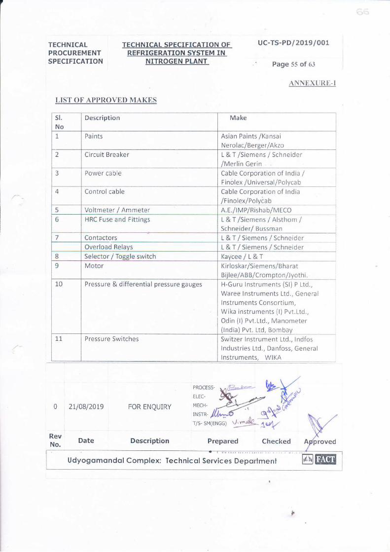
TECHNICALPROCUREMENTSPECIFICATION
TECHNICAL SPECIFICATION OFREFRIGERATION. SYSTEM IN
NITROGEN PLANT
uc-Ts-PD/2OL9IOOL
' Page 55 of 63
ANNEXURE-I
LIST OF APPROVED MAKES
sl.No
Description Make
1. Pa i nts Asian Paints /KansaiN erolac/Berger / Akzo
2 Circuit Breaker L & T /Siemens / Schneider/Merlin Gerin
3 Power cable Cable Corporation of lndia /Finolex /Universa l/Polyca b
4 Controlcable Cable Corporation of lndia
/F inolex/Polyiab5 Voltmeter / Ammeter A. E./lM P/Risha b/MECO
6 HRC Fuse and Fittings L&T/Siemens/Alsthom/Schneider/ Bussman
7 Contactors L & T / Siemens / SchneiderOverload Relays L & T / Siemens / Schneider
8 Selector / foeele switch Kaycee/L&T9 Motor Kirloska r/Sie me ns/B ha rat
Bijlee/AB B/Crom pton/Jyoth i.
10 Pressure & differential pressure gauges H-Guru lnstruments (Sl) P Ltd.,
Waree lnstruments Ltd., Generallnstruments Consortium,Wika instruments (l) Pvt.Ltd.,
Odin (i) Pvt.Ltd., Manometer(lndia) Pvt. Ltd, Bombay
1.1 Pressure Switches Switzer lnstrument Ltd., lndfoslndustries Ltd., Danfoss, Generallnstruments. WIKA
0
I
RevNo.
2110812019 FOR ENQUIRY
Date Description Prepared
Udyogomondol Complex: Technicol Services Oeportment
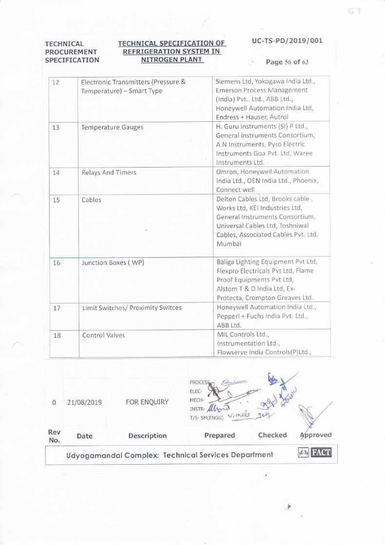
TECHNICALPROCUREMENTSPECIFICATION
TECHNICAL SPECIFICATION OFREFRIGERATION SYSTEM IN
NITROGEN PLANT
uc-Ts-PD/2019/001
' Page 56 of 63
t2 Electronic Transmitters ( Pressure &
Temperature) - Smart Type
Siemens Ltd, Yokogawa lndia Ltd.,
Emerson Process Management(lndia) Pvt.. Ltd., ABB Ltd.,
Honeywell Automation lndia Ltd,
Endress + Hauser, Autrol
13 Temperature Gauges H. Guru lnstruments (Sl) P Ltd.,
General instruments Consortium,A.N lnstruments, Pyro Electric
lnstruments Goa Pvt. Ltd, Waree
lnstruments LtC.'
1,4 Relays And Timers Omron, Honeywell Automationtndi; Ltd., oEN lndia Ltd., Phoenix,
Connect well
15 Cables Delton Cables Ltd, Brooks cable ,
Works, Ltd, KEI lndustries Ltd,
General I nstruments Consortium,Universal Ca bles Ltd, Toshniwa I
Cables, Associated Cables Pvt. Ltd.
Mumbai
L6 Junction Boxes ( WP) Baliga Lighting Equipment Pvt Ltd,
Flexpro Electricals Pvt Ltd, Flame
Proof Equipments Pvt Ltd,
Alstom T & D lndia Ltd, Ex-
Protecta, Crompton Greaves Ltd.
1,7 Limit Switches/ Proximity Switces Honeywell Automation I ndia Ltd.,
Pepperl + Fuchs lndia Pvt. Ltd.,
ABB Ltd.
18 Control Valves MIL Controls Ltd.,
lnstrumentation Ltd.,
Flowserve lndia Controls( P)Ltd.,
2110812019 FOR ENQUIRY
Description Frepared Checked
Udyogomondolcomplex: Technicolservices Deportmenl @ltEItft:: Date

TECHNICALPROCUREMENTSPECI FI CATI ON
I
l
l
TECHNI CAL SPECI FI CATION OFREFRI GERATI ON SYSTEM IN
NI TROGEN PLANT
uc-TS- PDI 2 0 r 9/ 00 r
Page 57 of 63
Forbe s Marshall ARCAPvI. Ltd.,
Fmerson Proce ss ManagementOrennai hd.,Dembla Valves (P)IJd.,
Desser valve India h,t. Ltd.
19 Solenoid Valve A,S@Numatics (INDIA) h4. Ltd.,
Fmerson.
20 On-OffValve - Solenoid Operated hstrumentation Ltd.,
MILControls Ltd.,
Fmerson Proce ss ManagementChennai Ird..Dresser valve trndia P\,1. Ltd.,
Flowserve l:rdia Controls@)Ltd.,
lioso India Private Ltd.,Virgo Valves & Controls Private
Lrd.,Tyco Valves & C-ontrols (D P ttd.,ARCAControls Ltd.
21 Se lf-Actuated Pre ssure Control Valves Desser valve India hrt. ftd.,Fmerson Process ManagementChennai Ltd.,
Nirmal Industrial Contro I P\4.Ltd.,
Samson Controls h,t. Ltd.
22 Prc Ro ckwe ll (ALLENBRADLE!,
Siemens Ltd.,
Honeyrvell Automation india Ltd.,
Schneider Electric Systems India,Ornron., ABBLtd.,Idec Izumi, Mitsubhishi.
21 10812019 FOR ENQUIRY
Date De script ion Prepared Checked
MECH-
msrx-,lllv,^?r/s- SMENGG) v,
i
RevNo. l
Udyoga ma nda I Comple x: fb c hnic a I Servic e s De pa rtm e nt [6lt$EI
,
pproved

I
TECHNICAL i
PROCUREMENTSPECIFICATION i
TECHNICAL SPECIFICATION OF I uc-TS-PDt20t9t 00
Page 58 of 63
REFRI GERATI ON SYSTEM INNI TROGEN PLANT
i ]
i
PRICED BID FORMAT
PROJECT
ENQUIRYNO
: MICROPROCESSER CONTROLLED REFRIGERATION SYSTEM 20 TR
IN NITROGEN PLANT
ANNEXURE _ II
T ---T l
EF t*"
lqS*W+-
I cnectea
l2U08t2019
Date
FOR ENQUIRY
Description
No Description QtyUnitPr ice
TotalPr ice
1.0Refrigeration System 20 TR in Nitrogenplant
1.1
Supply of Refrigeratioh system:
Design, mbnufacture, Testing & inspectionand Supply to FACT of the RefrigerationSystem 20 TR to FACT UC completeincluding commissioning spares as perTechnical Procurement Specifi cation (TPS).
I Lot
1.2
Third party inspection agencies (TPIA)charges for pre dispatch inspection ifapplicable (for overseas Vendors only)
I Lot.
1.3
E&C of Refrigeration System 20 TRincluding warranty:
Installation, Inspection and Testing,Commissioning, documentation, runningtest and site performance and officialhanding over to FACT of the Refriseration
1 Lot
Udyogamandal Complex: Technical Services Department [6JEE!trt
9

t.l
ll rBcnNr cer TECHNI CAL SPECIFI CATION OFREFRI GERATI ON SYSTEM IN
NITROGEN PLANT
uc-TS-PDt 2019t 001
Page 59 of 63
System 20 TR including providingguarantee/ warranty etc. in the scope of thevendor as per Technical ProcurementSpecification (TPS)
2.0
Comprehensive Annual MaintenanceContract (CAMC) services forRefrigeration System 20 TR (after thewarranty period) as follows
2.1
CAMC for l"Year (afterguarantee/warranty)
(4 quarter visits in a year)
I Lot
2.2CAMC for 2noYear . (4 quarter visits in ayear)
I Lot
Z,JCAMC for 3'oYear.( 4 quarter visits in ayear)
I Lot
Total Price (INR)
NOTE S:
1. The total Amount shall include all items and works covered in the scope of work of thevendor in the TPS.
2. The total evaluated cost of all the above items / activities put together shall formthe basis for selection of the successful bidder.
3. Bidder to fill all the columns for each item separately in the above format. Bids notconforming to this requirement is liable to be rejected.
Date: Name of the Bidder Seal & Signaturel
lI
0 21t08t2019 FOR ENQURY
PRocESS- (*-*')Qf \ ,_-MECH- /<)><, s-r*- fl,fidr/s- SMENGG) V.AIJ
ls(f
&y N
*:l ] Date ]
De scription Pre p are d Checked pproved
Udyoga ma'nda I Comple x: Te chnic a I Se rvic e s De pa rtm e nt 16ltilol
f

TECHNICALP ROCUREMENTSPECI FI CATI ON
2v0812019
TECHNI CAL SPECI FI CATI ON OFREFRI GERATI ON SYSTEM IN
NI TROGEN PLANT
uc-TS-PDt 20t9t 001
Page 60 of 63
ANNEXURE - III
RECOMMENDED SPARES BY THE VENDOR FOR TWO YEARS OPERATION -PRICED
Notes:
s$d
Sl No Description ofSpare Part
PartNo
Quantity Unit RateINR
AmountINR
FOR ENQURY
PRocESS- d4+r-'-,r.tp' ----MECH.
,*rr*-'/il^bT/S- SMENCG)
Udyoga ma nda I Comple x: Te c hnic a I Se rvic e s De pa rlme nt @llWI
-
,

TECHNI CAL SPECI.FI CATI ON OFREFRI GERATI ON SYSTEM IN
NI TROGEN PLANT
TECHNI CALPROCUREMENTSPECIFICATION
uc-TS-PDl20t9l 001
Pa ge
2.
3.
The Vendor shall submit the recommended list of spares for two years normal
operation for 20 TR new refrigeration unit and shall be quoted item wise
separately in the above format.
Items under these categories shall NOT be considered for price evaluation.
However FACT is at liberty to consider the type I category and extent of spares
to be ordered.
1
0 2U0812019I
FOR ENQLnRY
PROCESS- es-!e-
#:"wwsrx- /1J4.3r/s- sMENGG) vriY'^dt
w{,r
$ntMt \-7v',r I
ft:l I Date De scription Pre p are d Checked Approved
Udyogamanda I Comple x: Te chnic al Servic e s Departme nt
9

TECHNICAL ] TECHNICALSPECIFICATION OFPROCUREMENT i ngpRIGERATIoN SYSTEM TN
uc-TS-PDl2019t 001PROCUREMENT REFRIGERATION SYSTEM INSPECIFICATION NITROGEN PLANT Page 62 of 63
ANNEXURE IVCOMPLIANCE STATEMENT
ENQUIRY No :
We state that our offer No ...... is in full compliance
with the documents issued against the Enquiry No .......: except for the
deviations listed below:-
LIST OF DEVIATIONS / EXEMPTIONS
No Description Reasons for Deviation
We have read, understood and accepted the terms and conditions of this enquiry covered inTechnical Procurement Specifications, for Design, Supply, Installation & Commissioningand Comprehensive Annual Maintenance Contract as attached with the tender documents,except for the above.
Date: Name of the Bidder Seal & Signature
21108120t9 FOR ENQUTRY
Date
0
l!
ll
Udyoga m a nda I Comp le x: Te c hnic a I Se rvic e s De pa rtme nt @JfEA
