october 2015 performance validation for the mobile core · figure 9 mme unique configuration...
TRANSCRIPT

October 2015
Performance validation for the mobile core
Are you ready for Terabits of Traffic?

EPC and virtualization, the impact on performance validation
© 2015 Cobham - 2 -
Performance validation for the mobile core
1 EPC and virtualization, the impact on performance validation ............................................................ 3
1.1 Elastic and scalable performance validation for EPC ..........................................................................................4 1.2 3GPP mobility performance validation .................................................................................................................6
1.3 Introducing TeraVM, mobile core performance validation solutions .....................................................................6 1.4 EPC performance validation, enabling terabits of traffic ......................................................................................9
2 Defining a flexible test strategy for vEPC ............................................................................................. 10
2.1 Validation of call and traffic modelling at terabits per second ............................................................................. 10 2.2 Validation for RAN modelling ............................................................................................................................ 11
3 Per bearer, per application performance validation ............................................................................ 12
3.1 What is the relevance of per bearer and real world users? ................................................................................ 12
3.2 Stateful bearers, real bearer traffic .................................................................................................................... 13 3.3 Voice Content ................................................................................................................................................... 13 3.4 Adding mixed traffic flows, support multiple bearers .......................................................................................... 13
4 EPC performance validation strategy ................................................................................................... 14
4.1 TeraVM EPC configuration options ................................................................................................................... 14
4.2 Signaling, Transaction and Capacity rate testing ............................................................................................... 19 4.3 Performance validation for Voice over LTE (VoLTE/secure VoLTE) .................................................................. 20
4.4 TeraVM voice application test scenarios ........................................................................................................... 22
5 Conclusion .............................................................................................................................................. 24
6 Appendices – TeraVM available performance statistics ..................................................................... 25
6.1 TeraVM mobile core sample statistics ............................................................................................................... 25
6.2 TeraVM sample application statistics ................................................................................................................ 35 6.3 Dual Hosted VoIP Application Results............................................................................................................... 39
6.4 Supported Voice Codecs .................................................................................................................................. 40 6.5 Supported Video/Audio and Voice Codecs ........................................................................................................ 41
Table of Figures
Figure 1 Platform validation scenario - opensource versus proprietary cloud managed platforms ...................................... 5
Figure 2 TeraVM EPC modular architecture – emulate any of the core mobile nodes ........................................................ 7
Figure 3 EPC performance validation using standard hardware ......................................................................................... 9
Figure 4 TeraVM enables dynamic call and traffic modelling ............................................................................................ 10
Figure 5 TeraVM emulating mobile handover in standard hardware ................................................................................. 11
Figure 6 TeraVM template configurations; subscriber profile and UE settings .................................................................. 14
Figure 7 LTE handover templates; enable ease of configuration by simply selecting a profile .......................................... 15
Figure 8 TeraVM emulated RAN settings ......................................................................................................................... 16
Figure 9 MME unique configuration settings per emulated MME ...................................................................................... 17
Figure 10 TeraVM gateway emulation settings ................................................................................................................ 18
Figure 11 TeraVM emulating overload scenarios on EPC core ........................................................................................ 21

EPC and virtualization, the impact on performance validation
© 2015 Cobham - 3 -
Performance validation for the mobile core
1 EPC and virtualization, the impact on performance validation
In the age of virtual network functions (VNF), do we expect call modelling or traffic
modelling to be accurate enough to enable selection of the correct components for the
next generation of the mobile network core?
Perhaps? However, the question many people are asking is - what impact do the founding
pillars for Network Function Virtualization (NFV), as outlined in the ETSI ISG NFV
whitepaper*, have on these theoretical modelling algorithms?
For many carriers, NFV has the potential to enable greater agility such as ease of scale
on their core platforms. Carriers may be looking to expand revenues sources by enabling
a mobile virtual network operator (MVNO). Here the carrier may look to scale the mobile
core by using with a virtual EPC (vEPC) running on standard hardware.
Traditional modelling techniques for capacity enables the carrier to make informed
decisions on physical network infrastructure required to enable a network deployment at
a given scale. However, for a vEPC which can scale out/up on demand, this produces
many unknowns, how will the core behave when running across a number of hosts, what
happens if compute resources are not available, etc?
vEPC clearly offers many unique advantages, however carriers must have the confidence
in the reliability and robustness of these components, ensuring the infrastructure and
software components deliver the five 9’s of service reliability that carriers are custom to.
To validate robustness and reliability requires a well defined test strategy, which is the
purpose of this application note. However, before delving into a test strategy, it’s worth
considering what test tools/vendors are needed to facilitate performance validation for the
elastic and virtual mobile network core.
Carriers have made significant investment over the years, purchasing physical test
appliances and many perceive that there is no need to change. At Cobham Wireless, we

EPC and virtualization, the impact on performance validation
© 2015 Cobham - 4 -
know of carriers who started down this path, believing their physical test appliances which
they connected to the datacentre infrastructure through physical interfaces were good
enough. With our help they quickly realized that they were on the back foot in determining
performance in the virtualization layer and when it came to validation of the VNF vendor,
there was an even greater challenge.
As the elastic core scaled, they had no way of following these virtual machine instances
across the datacentre, or even dynamically scaling to ensure all new instances were
included in the performance validation. With annual budgets already tight, the wrong test
tool/vendor selection can result in projects been frozen for a year, which means at a
corporate management level they are even further away from capitalizing on the benefits
of NFV.
At management level the question now becomes is it viable to continue to support
modelling and proprietary hardware solutions for selection and performance validation of
our mobile core, especially as it is no longer supporting our needs? What’s the alternative?
Clearly a new approach to validation of the mobile core is needed, one which enables
elasticity and flexibility, facilitating ease of scale, ensuring a complete and accurate
assessment of the new virtual mobile core.
1.1 Elastic and scalable performance validation for EPC
As already highlighted, traditional modelling and use of proprietary hardware is no longer
relevant especially when it comes to vEPC performance validation. What’s the alternative?
The answer lies with the keywords of elastic and scale. TeraVM has from its inception
adopted these core principles, underpinning the product architecture. Cobham Wireless
TeraVM elastic test bed enables the user to scale as needed to meet the demand and
scale of the deployment of the vEPC.

EPC and virtualization, the impact on performance validation
© 2015 Cobham - 5 -
TeraVM is agnostic to the underlying hardware and virtualization layers, so it can be turned
up in many places enabling carriers and vendors to performance test a number of
deployment options.
Many carriers start the performance validation cycle for vEPC by evaluating and
comparing the two deployment options: 1) proprietary technology e.g. VMware versus 2)
opensource community equivalent e.g. OpenStack.
Figure 1 Platform validation scenario - opensource versus proprietary cloud managed platforms
In Figure 1 above, the vEPC component will be deployed on both cloud managed
platforms enabling carriers to determine the pros and cons of each option. From a test
and measurement perspective this means the test solution selected must be deployable
and managed on both platforms. This also means that TeraVM and vEPC has support for
multiple hypervisors i.e. KVM, ESXi, Hyper-v, etc.

EPC and virtualization, the impact on performance validation
© 2015 Cobham - 6 -
1.2 3GPP mobility performance validation
A fundamental challenge in validating the network core, is how to present and test the
mobility aspects, this includes movement between cell locations or the user equipment
(UE) handing over between radio access technologies (RAT), which may include fall back
from 4G to 3G.
As the vEPC is deployed into datacentre like infrastructure, the challenge is how to
represent multiple radio access technologies (RAT) in the datacentre. Physically, it’s
impossible to role in multiple radio heads and therefore necessary to emulate them.
To enable accurate testing of call modelling, it will be necessary to represent the UE at
scale but more importantly simulate the UE movement.
1.3 Introducing TeraVM, mobile core performance validation solutions
TeraVM offers a complete end-to-end solution for physical and virtual EPC testing.
TeraVM’s modular architecture is made up of a number of virtual machines and is
datacentre ready. Carriers can use standard hardware and/or orchestrate into their
datacentres alongside the vEPC.
The modular architecture enables the necessary flexibility to wrap around the complete
core or simply isolate a component of the EPC VNF deployment e.g. validate performance
of the mobility management entity (MME) in standalone.
A further advantage of the TeraVM approach, is that a single host can emulate the
complete core functionality i.e. no need for multiples of dedicated proprietary units to fulfil
various node functions. This enables the user to easily slot in any of the EPC nodes for
wrap around testing; performance validate for bottlenecks in the VNF EPC deployment.
Users of TeraVM can simply select the required interfaces to expose and load traffic on
e.g MME expose S1-MME, S6a and S5, create load scenarios on interfaces.
EPC and virtualization, the impact on performance validation
© 2015 Cobham - 7 -
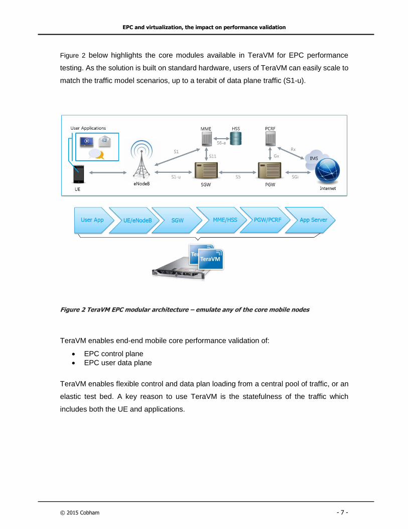
Figure 2 below highlights the core modules available in TeraVM for EPC performance
testing. As the solution is built on standard hardware, users of TeraVM can easily scale to
match the traffic model scenarios, up to a terabit of data plane traffic (S1-u).
Figure 2 TeraVM EPC modular architecture – emulate any of the core mobile nodes
TeraVM enables end-end mobile core performance validation of:
EPC control plane
EPC user data plane
TeraVM enables flexible control and data plan loading from a central pool of traffic, or an
elastic test bed. A key reason to use TeraVM is the statefulness of the traffic which
includes both the UE and applications.

EPC and virtualization, the impact on performance validation
© 2015 Cobham - 8 -
TeraVM supports stateful:
UE procedures: ATTACH/DETACH, Authentication
Mobility: Handover (3G->4G), Circuit Switch fallback (3G) o SRVCC (3GPP Rel. 8) o eSRVCC (3GPP Rel. 10) o rSRVCC (3GPP Rel. 11)
Application Traffic: Per UE, real applications of Voice, Video incl. MPEG-DASH and Data
Together we can deliver the five 9’s of service reliability for vEPC enabling continuity in
service success for NFV deployments.

EPC and virtualization, the impact on performance validation
© 2015 Cobham - 9 -
1.4 EPC performance validation, enabling terabits of traffic
The purpose of the application note, is to outline a test strategy for EPC performance
validation, enabling highly scaled load capability up to 1Tbps. One which is built on
standard hardware, helping to keep costs minimal. In doing so, it will introduce a new
concept of the elastic test bed, enabling ease of scale.
Figure 3 EPC performance validation using standard hardware
Figure 3 outlines the basic architecture of the test bed built on datacentre ready hardware.
TeraVM is used to simulate the scenario of UEs attaching to the network and sending
traffic on the S1-u interface, enabling up to 1 Terabit per second of user plan traffic.
This application note will define the test strategy and will outline the relevance of per
bearer per application performance validation.

Defining a flexible test strategy for vEPC
© 2015 Cobham - 10 -
2 Defining a flexible test strategy for vEPC
2.1 Validation of call and traffic modelling at terabits per second
Call modelling focuses on the UE capabilities, the ability to connect to the mobile network.
In this use case TeraVM delivers a number of templated scenarios e.g. UE attach,
authentication and detach after a period at the scale of millions of UEs.
The dynamic capability of the TeraVM means the emulated load can then be dynamically
switched from the S1 interface to S1-u modelling the traffic scenarios on the carrier
network.
Real world load scenarios require equivalent load capabilities at terabits per second on
the S1-u interfaces. TeraVM running on standard hardware makes it extremely easy to
scale in a cost efficient way, without breaking the bank.
Figure 4 TeraVM enables dynamic call and traffic modelling
Defining a flexible test strategy for vEPC
© 2015 Cobham - 11 -
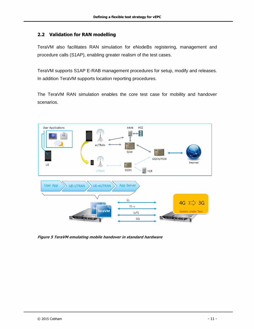
2.2 Validation for RAN modelling
TeraVM also facilitates RAN simulation for eNodeBs registering, management and
procedure calls (S1AP), enabling greater realism of the test cases.
TeraVM supports S1AP E-RAB management procedures for setup, modify and releases.
In addition TeraVM supports location reporting procedures.
The TeraVM RAN simulation enables the core test case for mobility and handover
scenarios.
Figure 5 TeraVM emulating mobile handover in standard hardware

Per bearer, per application performance validation
© 2015 Cobham - 12 -
3 Per bearer, per application performance validation
3.1 What is the relevance of per bearer and real world users?
Per bearer in its purest form means no two bearers are the same, exactly how real world
subscribers connect and communicate on the network today. Per bearer coupled with user
application emulation enables testing with flows with precise details and properties i.e.
device credentials IMSI, IMS SIP configurations and stateful media for Voice and/or Video
over LTE.
The true benefit to per bearer testing is the ability to provide performance metrics on each
and every UE and the associated application flows such as SIP and RTP. The importance
of a granular approach becomes evident for policy and charging, ensuring that each UE
and activity are accurately recorded, ensuring subscribers are billed/managed correctly,
while active on the network.
To further enhance the test strategy, the test should easily scale to the correct number of
unique subscribers. For example TeraVM supports up to 8,000,000 active bearers each
with unique activities i.e. making calls, sending emails or even watching video.
Note: In reference to TeraVM application flows, each flow is a 5-tupple, in which all
elements of the flow are configurable:
1. Source IP
2. Destination IP
3. Source Port
4. Destination Port
5. Protocol

Per bearer, per application performance validation
© 2015 Cobham - 13 -
3.2 Stateful bearers, real bearer traffic
In the real world, voice conversations are generally two way or bi-directional therefore it
should be considered as a pre-requisite for the test strategy that the traffic flows are
stateful and bi-directional i.e. understand and respond to individual and unique control and
transport layer requests.
The purpose of using stateful traffic flows in EPC test strategies include:
1) Real calls and codecs (NB and/or WB- AMR codecs).
a. Using fixed, stateless, bit patterns offer no reflection of real network
conditions, offering no perspective on user quality of experience
2) Connect to auxiliary services such as IMS
3) Determine the impact/accuracy that network management (e.g. PCEF) has on
an individual endpoint’s performance.
4) Percentage of overall network bandwidth given over to control signals versus
goodput of actual application flows.
3.3 Voice Content
It’s vital to add real voice samples to each bearer, which may include encrypted RTP
media. An ideal test will be to use different codecs and encryptions. This helps to
determine network reliability but is also useful in testing SIP proxy or call handlers to block
calls between endpoints which are incompatible.
3.4 Adding mixed traffic flows, support multiple bearers
The mobile core will support multiple bearers. Performance testing must include a mix of
traffic from a range of applications which includes the use of multiple APN assignments.
In short, the greater the variety of subscriber activities the more realistic the testing
scenarios become, offering the greatest amount of test coverage and efficiency in testing.

EPC performance validation strategy
© 2015 Cobham - 14 -
4 EPC performance validation strategy
4.1 TeraVM EPC configuration options
TeraVM’s integrated configuration and performance measurements facilitates users with
flexible configuration options. TeraVM is template driven, enabling users to quickly select
any number of scenarios for call and traffic modelling, from a centralized library of tests.
Templates enable ease of use, providing a minimal touch configuration experience.
4.1.1 Subscriber settings
Users can configure up to 8,000,000 active bearers with the ability to assign unique traffic
profile templates e.g. Teenagers - lots of video activity, Commuters – simulating
movement, consuming lots of data bandwidth, Business – mixed voice and data
applications such as email.
Figure 6 TeraVM template configurations; subscriber profile and UE settings

EPC performance validation strategy
© 2015 Cobham - 15 -
In addition, users can assign unique UE credentials of IMSI, MISDN and unique APN.
TeraVM supports multiple bearers per UE, each bearer supporting any mix of user
applications.
TeraVM simplifies user configurations via the use of templates. Figure 7 below is an
example profile for commuters; simulating mobility. This results in all the UEs in the
associated profile taking part in the simulated handover for Inter MME.
Figure 7 LTE handover templates; enable ease of configuration by simply selecting a profile
The emulated UE supports stateful network access stratum (NAS) procedures (Attach /
Authenticate / Mobility / Integrity / Cipher). This provides for effective call modelling
capacity validation strategy, in which the result is based on the number of NAS (signaling
events) per busy hour.
EPC performance validation strategy
© 2015 Cobham - 16 -
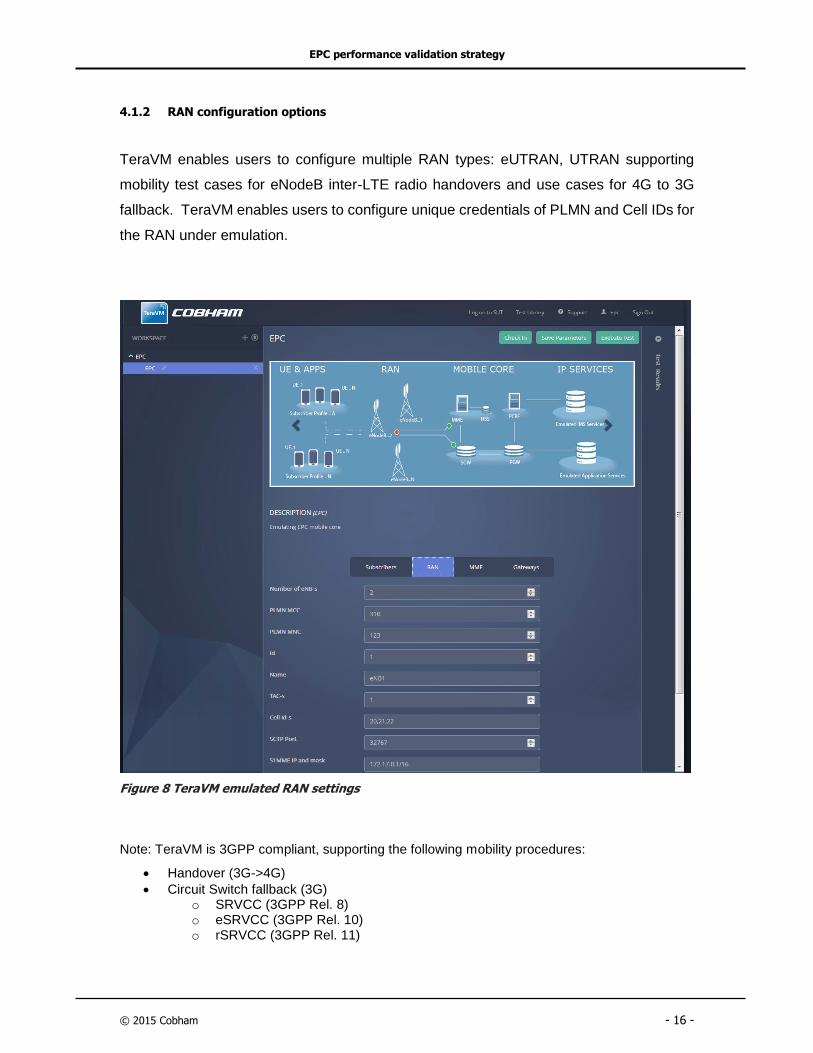
4.1.2 RAN configuration options
TeraVM enables users to configure multiple RAN types: eUTRAN, UTRAN supporting
mobility test cases for eNodeB inter-LTE radio handovers and use cases for 4G to 3G
fallback. TeraVM enables users to configure unique credentials of PLMN and Cell IDs for
the RAN under emulation.
Figure 8 TeraVM emulated RAN settings
Note: TeraVM is 3GPP compliant, supporting the following mobility procedures:
Handover (3G->4G)
Circuit Switch fallback (3G) o SRVCC (3GPP Rel. 8) o eSRVCC (3GPP Rel. 10) o rSRVCC (3GPP Rel. 11)

EPC performance validation strategy
© 2015 Cobham - 17 -
4.1.3 MME settings
TeraVM supports emulation of multiple MME with unique configuration parameters.
TeraVM MME is fully stateful and supports S1AP messaging up to 60,000 messages per
second. The emulated MME complies with 3GPP RAN setup and UE handover
procedures, which include tracking area updates per emulated UE.
Figure 9 MME unique configuration settings per emulated MME

EPC performance validation strategy
© 2015 Cobham - 18 -
4.1.4 Gateways and Application server settings
TeraVM emulates all the gateway functions of the EPC, which include emulation of IMS
services. TeraVM stateful application emulation enables users to emulate their own
application servers or indeed connect to a 3rd party service for voice, video and data
applications.
The stateful gateways and interface means users can plug-in their own nodes and validate
performance of the node which includes MME, HSS and PCRF.
Figure 10 TeraVM gateway emulation settings
EPC performance validation strategy
© 2015 Cobham - 19 -
4.2 Signaling, Transaction and Capacity rate testing
The following sections summarizes the required test steps to enabling a complete
validation strategy for EPC. EPC performance validation can be broken down into a
number of core steps enabling an efficient testing procedure ensuring the widest
coverage, this includes testing for signaling, transactions and capacity rates. TeraVM
provides templates for each scenario.
4.2.1 Signaling validation procedures
Management Procedures o S1 Setup
Attach o EPS Attach o EPS/IMSI Combined Attach o GUTI Attach o Emergency Attach
Tracking Area Updates o Inter-MME Tracking Area Update o Intra-MME Tracking Area Update
Intra-LTE Handover o S1-based HO (MME unchanged) o S1-based HO (MME changed)
Inter-RAT HO o Inter-RAT PS Handover E-UTRAN to UTRAN (SGW unchanged) o Inter-RAT PS Handover E-UTRAN to UTRAN (SGW changed) o Inter-RAT PS Handover UTRAN to E-UTRAN (SGW unchanged) o Inter-RAT PS Handover UTRAN to E-UTRAN (SGW changed)
Bearer Modification o UE initiated bearer modification with bearer QoS Update
4.2.2 Transaction rate validation
Attach / Detach rate
Bearer Activation/Deactivation rate
Dedicated Bearer Activation/Deactivation rate
Tracking Area Update Rate
4.2.3 EPC capacity test procedures
Maximum number of eNB/HeNB per MME/SGW
Maximum number of UE’s per MME/SGW
Maximum number of GTP tunnels per SGW
Maximum number of supported APN’s

EPC performance validation strategy
© 2015 Cobham - 20 -
4.3 Performance validation for Voice over LTE (VoLTE/secure VoLTE)
An EPC test strategy will include validation of both the UE and voice application
UE Assessment:
How fast can the UE attach and authenticate with the MME/HSS?
Provisioning the bearer – how fast can the EPC allocate multiple bearers?
IMS services – how quick is the SIP proxy/registration authentication
process?
Inbound / Outbound Connectivity – Is the SIP proxy server routing
configuration correct?
Media Encryption – Can calls be sustained with encrypted media flows
(SRTP)?
Call Media Quality – How much latency is tolerable by the subscriber?
The above is a sample of just a single UE’s media session, in real world terms the process
occurs over thousands of unique UEs. Therefore testing needs to be scalable, not
forgetting that communication is a two way flow, with various handshaking and
negotiations e.g. (SIP Invite/Bye, TCP window resizes, etc).
Scalability Test Scenarios:
Oversubscription of UEs – Examine the fallout when all UEs attach at the
same time, will the EPC scale out?
Call throughput – Determine the maximum concurrent calls possible, in a
pure VoIP only situation. Re-examine when additional traffic types are
added to the mix?
Emergency Call handling – Using the above examples, examine how 911
calls are handled.

EPC performance validation strategy
© 2015 Cobham - 21 -
Figure 11 TeraVM emulating overload scenarios on EPC core

EPC performance validation strategy
© 2015 Cobham - 22 -
4.4 TeraVM voice application test scenarios
1. SIP Registration – Test functionality and performance timing. Connect and register
with the SIP registration server with unique details and passwords. Determine
maximum number of registrations possible on a per second basis.
2. Interact with 3rd Party Servers – Emulated endpoints are fully stateful, and can
interact with a number of leading vendor’s equipment e.g. connect to a IMS service,
plus make RTP and SRTP calls.
3. Call Quality - Establish a baseline reference call for voice quality – establish the most
suitable codec and optimal buffer sizes for devices under varying networking
conditions.
4. Bulk Call Capabilities – Establish the maximum number of calls possible, use a mix
of traffic flows with signaling only and signaling plus media.
5. Load Testing (up to terabits of S1-u load) - Test and measure voice quality under
varying traffic conditions and network loads, on a per client / per flow basis. Mix several
unique individual voice, multicast video and multiple data clients running service
applications.
Run true, stateful TCP based application flows along with voice flows with
multiple codecs. Exchange real voice, access real multicast streams, e-mail
documents, URLs and attachments in order to emulate realistic, per client
traffic flows.
6. IPv6 transition testing – Utilize unique layer 2/3 properties, concurrently examine
performance of IPv4 versus IPv6 enabled voice applications. Examine performance of
dual stack enabled UACs, investigate the ability to register/connect calls using IPv4 or
IPv6.
This provides a unique MAC and IP address per client. The flexible MAC
address configuration and unique options assignment is key for validating
security in many environments.
EPC performance validation strategy
© 2015 Cobham - 23 -
7. IMS enabled Multimedia calls – Analyze the SIP registration performance. Examine
RTP performance and the incoming media quality.
8. Secure calls through TLS/SSL – Measure and compare performance of secure
(TLS/SSL) and unsecure voice calls. Determine if by varying the codec type has any
influence on performance in TLS/SSL sessions.
9. NAT boundary traversal - Measure the effects of NAT boundary traversal (RFC 3261)
on call quality.
10. Disruptive flows (P2P, DDOS, IGMP floods, spam, and viruses) – add to the existing
test scenarios, test and verify any security and mitigation rules or functionality that may
be available.
11. Network device QoS Settings - Run individual voice, multicast and application data
on emulated hosts against external voice, multicast and application data servers. Test
and verify appropriate QoS mechanisms to use at L2 and/or L3/4 to classify traffic into
each service category. Assign VLAN priority (on single and tunneled QinQ) on
emulated endpoints and DiffServ/TOS classification for each individual
application/service.

Conclusion
© 2015 Cobham - 24 -
5 Conclusion
The TeraVM mobile network core performance validation solution provides
unprecedented scale when it comes to validation of mobile cores. TeraVM delivers the
realism of modern mobile network subscribers, enabling validation with terabits of
subscriber application traffic.
TeraVM is a virtualized solution, based on a modular architecture, which provides
numerous mobile test use cases, enabling validation for end-to-end mobile scenarios or
is used to validate unique mobile core nodes i.e. in a wrap-around scenario.
A key reason for choosing TeraVM is the realism of its UE and applications. TeraVM
enables unique configurations per UE and enables users represent mobility of subscribers
i.e. traversing a 4G network or falling back to 3G. TeraVM is fully compliant with 3GPP
standards.
The use of standard hardware makes it extremely cost efficient to scale to terabits of traffic
for validation of the mobile core. TeraVM’s elastic test bed offers unique capabilities in
scaling the test bed and also in terms of managing test scenarios. TeraVM offers a
centralized test library ensuring any knowledge learned is easily accessible by other users.
TeraVM’s templated approach to enabling subscriber, UE and traffic scenario profiles,
makes it extremely easy for users to quickly represent unique subscribers and applications
on a per bearer basis. Per bearer validation enables a highly accurate interpretation on
how the mobile core will perform under varying models of call and traffic load scenarios.
TeraVM is NFV ready, which means carriers and equipment vendors can deploy the
validation solution alongside their vEPC in the datacenter cabinets. TeraVM is the only
solution to offer mobility test scenarios for EPC VNFs. Validation includes handover
scenarios like 4G to 3G - all on standard hardware.
TeraVM is the only solution which delivers proven scale of terabits of traffic for
performance validation of mobile network cores, in a cost effective manner.

Appendices – TeraVM available performance statistics
© 2015 Cobham - 25 -
6 Appendices – TeraVM available performance statistics
6.1 TeraVM mobile core sample statistics
Sessions Initiated The number of default and dedicated bearer sessions that have been initiated.
Sessions Succeeded The number of default and dedicated bearer sessions that succeeded.
Sessions Failed The number of default and dedicated bearer sessions that failed.
Sessions Failed Due To Resource Exhaustion
Number of Attaches rejected because internal resources were exhausted. This indicates that the UE count may need to be increased or the Attach load is not balanced between CPUs.
IPv4 Sessions Initiated The number of IPv4 bearer sessions that have been initiated.
IPv6 Sessions Initiated The number of IPv6 bearer sessions that have been initiated.
Rx Attach Request The number of Attach Requests received from the UE, as part of an attach procedure.
Tx Attach Accept
The number of Attach Accept messages sent from the network to the UE. This message is sent to the UE to indicate that the corresponding attach request has been accepted.
Rx Attach Complete The number of Attach Complete messages received from the UE. This message is sent by the UE in response to an Attach Accept message.
Tx Attach Reject
The number of Attach Reject messages that the network sent to the UE. This message is sent to the UE to indicate that the corresponding attach request has been rejected.
Rx PDN Connectivity Request The number of PDN Connectivity Request messages received from the UE. This message requests establishment of a PDN connection.
Tx Activate Default Bearer Request The number of Activate Default EPS Bearer Context Request messages sent to the UE. This message requests activation of a default EPS bearer context.
Rx Activate Default Bearer Accept
The number of Activate Default EPS Bearer Context Accept messages received from the UE. This message acknowledges activation of a default EPS bearer context.
Tx Information Request
The number of Information Request messages sent to the UE. This message is sent to the UE to request ESM (EPS Session Management) information (protocol configuration options, APN, or both).
Rx Information Response
The number of Information Response messages received from the UE. This message is sent by the UE to the network in response to an Information Request message; it provides the requested ESM (EPS Session Management) information.

Appendices – TeraVM available performance statistics
© 2015 Cobham - 26 -
Rx Detach Request (switch off) The number of Detach Requests received from the UE, in which the Switch Off parameter indicates that the request is the result of a switch off situation.
Rx Detach Request (normal)
The number of Detach Requests received from the UE, in which the Switch Off parameter indicates that the request is the result of a normal detach (and not the result of a switch off situation).
Tx Detach accept
The number of Detach Accept messages sent to the UE received. This message is sent to the UE to indicate that the UE-originating detach procedure has been completed.
Tx Authentication Request
The number of Authentication Request messages sent to the UE. This message initiates authentication of the UE identity. The network initiates the Authentication Procedure by sending an Authentication Request message to the UE and starting the T3460 timer. The Authentication Request message contains the parameters necessary to calculate the authentication response (refer to 3GPP TS 33.401 for detailed information).
Rx Authentication Response The number of Authentication Response messages received from the UE. This message delivers a calculated authentication response to the network.
Rx Authentication Failure
The number of Authentication Reject messages received from the UE. (The MME sends an Authentication Request to the UE, and the UE responds with either an Authentication Response or a Reject message.)
Tx Authentication Reject
The number of Authentication Reject messages sent to the UE. The Authentication Reject message is sent by the network to the UE to indicate that the authentication procedure has failed and that the UE must abort all activities.
Tx Security Mode Command The number of Security Mode Command messages sent to the UE. This command is used to establish NAS signaling security.
Rx Security Mode Complete The number of Security Mode Complete messages received from the UE in response to the Security Mode Command messages received.
Tx Identity Request
The number of Identity Request messages that the network sent to the UEs. This message is sent by the network to the UE to request that the UE provide the specified identity.
Rx Identity Response
The number of Identity Response messages that the network received from the UEs. This message is sent by the UE to the network in response to an Identity Request message; it provides the requested identity.
Rx Security Mode Reject
The number of Security Mode Reject messages received from the UE. This message indicates that the corresponding Security Mode Command has been rejected.
Tx Paging The number of Paging messages sent to the UEs.
Rx Service Request The number of Service Request messages received from the UEs. The service request message is sent by the UE to the

Appendices – TeraVM available performance statistics
© 2015 Cobham - 27 -
network to request establishment of a NAS signaling connection and establishment of radio and S1 bearers.
Tx Service Reject The number of Service Reject messages sent to the UEs.
ESM Insufficient Resources This ESM cause is used by the UE or by the network to indicate that the requested service cannot be provided due to insufficient resources.
ESM Unknown or Missing APN This ESM cause is used by the network to indicate that the access point name was not included or could not be resolved.
ESM Auth Failed This ESM cause is used by the network to indicate that the requested service was rejected by the external packet data network due to a failed user authentication.
ESM Request Rejected by Serving GW or PDN GW
This ESM cause is used by the network to indicate that the requested service or operation or the request for a resource was rejected by the Serving GW or PDN GW.
ESM Request Rejected, unspecified
This ESM cause is used by the network or by the UE to indicate that the requested service or operation or the request for a resource was rejected due to unspecified reasons.
ESM Regular Deactivation This ESM cause is used to indicate a regular UE or network initiated release of EPS bearer resources.
ESM Network Failure This ESM cause is used by the network to indicate that the requested service was rejected due to an error situation in the network.
ESM PDN type IPv4 only allowed This ESM cause is used by the network to indicate that only PDN type IPv4 is allowed for the requested PDN connectivity.
ESM PDN type IPv6 only allowed This ESM cause is used by the network to indicate that only PDN type IPv6 is allowed for the requested PDN connectivity.
ESM information not received This ESM cause is used by the network to indicate that the PDN connectivity procedure was rejected due to the ESM information was not received.
EMM Unknown IMSI This EMM cause is sent to the UE if the UE is not known (registered) in the HSS".
EMM IMEI not accepted This cause is sent to the UE if the network does not accept an attach procedure for emergency bearer services using an IMEI.
EMM UE cannot be derived by network
This EMM cause is sent to the UE when the network cannot derive the UE's identity from the GUTI/S-TMSI/P-TMSI and RAI e.g. no matching identity/context in the network or failure to validate the UE's identity due to integrity check failure of the received message.
EMM Network Failure This EMM cause is sent to the UE if the MME cannot service an UE generated request because of PLMN failures.
EMM ESM Failure This EMM cause is sent to the UE when there is a failure in the ESM message contained in the EMM message.
EMM Congestion This EMM cause is sent to the UE because of congestion in the network (e.g. no channel, facility busy/congested etc.).

Appendices – TeraVM available performance statistics
© 2015 Cobham - 28 -
EMM Message type not implemented The number of EMM messages that returned EMM cause code 97 (Message type non-existent or not implemented).
Rx S1 Setup Request
Rx S1 Setup Request
The number of S1 Setup Request messages received from the eNodeB. This message is sent by the eNodeB to the MME to transfer information for a transport network layer (TNL) association. The purpose of the S1 Setup procedure is to exchange application level data needed for the eNodeB and MME to interoperate on the S1 interface. This procedure is the first S1-AP procedure triggered after the TNL association has become operational. The procedure uses non-UE associated signaling.
Tx S1 Setup Response
The number of S1 Setup Response messages that the MME(s) sent to the eNodeB. This message is sent by the MME to the eNodeB to transfer information for a transport network layer (TNL) association.
Tx S1 Setup Failure
The number of S1 Setup Failure messages that the MME(s) sent to the eNodeB. This message is sent by the MME to the eNodeB to indicate a failure of the S1 Setup procedure.
Rx Initial UE Msg
The number of Initial UE Message messages received from the eNodeB. The purpose of the NAS Transport procedure is to carry UE/MME signaling over the S1 Interface. When the eNodeB has received from the radio interface the first UL NAS message transmitted on an RRC connection to be forwarded to an MME, the eNodeB invokes the NAS Transport procedure and sends the Initial UE Message message to the MME including the NAS message as a NAS-PDU IE.
Tx DL NAS Transport
The number of DOWNLINK NAS TRANSPORT messages that the MME(s) sent to the eNodeB. If the MME sends a NAS message transparently via the eNodeB to the UE and a UE-associated logical S1-connection exists for the UE or if the MME has received the eNB UE S1AP ID IE in an INITIAL UE MESSAGE message, the MME sends a DOWNLINK NAS TRANSPORT message to the eNodeB including the NAS message as a NAS-PDU IE. If the UE-associated logical S1-connection is not established, the MME allocates a unique MME UE S1AP ID to be used for the UE and includes that in the DOWNLINK NAS TRANSPORT message.
Rx UL NAS Transport
The number of UPLINK NAS TRANSPORT messages received from the eNodeB. When the eNodeB receives a NAS message from the radio interface to be forwarded to the MME to which a UE-associated logical S1-connection for the UE exists, the eNodeB sends the UPLINK NAS TRANSPORT message to the MME, including the NAS message as a NAS-PDU IE.

Appendices – TeraVM available performance statistics
© 2015 Cobham - 29 -
Rx NAS Non Delivery
The number of NAS NON DELIVERY INDICATION messages received from the eNodeB. This message is sent from the eNodeB to the MME when the eNodeB decides to not start the delivery of a NAS message that has been received over a UE-associated logical S1-connection; or the eNodeB is unable to ensure that the message has been received by the UE.
Tx Initial Context Setup
The number of Initial Context Setup Request messages that the MME(s) sent to the eNodeB. This message is sent by the MME to the eNodeB to request the setup of a UE context. The purpose of the Initial Context Setup procedure is to establish the necessary initial UE Context, including ERAB context; the Security Key; Handover Restriction List; UE Radio capability; UE Security Capabilities; and so forth. The procedure uses UE-associated signaling.
Rx Initial Context Response
The number of Initial Context Setup Request messages received from the eNodeB. This message is sent by the eNodeB to the MME to confirm the setup of a UE context.
Rx Initial Context Setup Response Fail The number of Initial Context Setup Failure messages received from the eNodeB.
Rx UE Context Release Request
The number of UE Context Release Request messages received from the eNodeB. This message is sent by the eNodeB to the MME to request the release of the UE-associated S1-logical connection over the S1 interface.
Tx UE Context Release Command
The number of UE Context Release Command messages that the MME(s) sent to the eNodeB. This message is sent by the MME to the eNodeB to request the release of the UE-associated S1-logical connection over the S1 interface.
Rx UE Context Release Complete
The number of UE Context Release Complete messages received from the eNodeB. This message is sent by the eNodeB to the MME to confirm the release of the UE-associated S1-logical connection over the S1 interface.
Tx Erab Setup Request
The number of E-RAB Setup Request messages that the MME(s) sent to the eNodeB. This message is sent by the MME to the eNodeB to request the assignment of resources on Uu and S1 for one or several E-RABs.
Rx Erab Setup Response
The number of E-RAB Release Response messages received from the eNodeB. This message reports the outcome of the request made by the E-RAB Release Request message.
Rx Erab Release Indication
The number of E-RAB Release Indication messages received from the eNodeB. This message is sent by the eNodeB to indicate that the MME should release one or several E-RABs for one UE.
Tx Erab Release Command
The number of E-RAB Release Command messages that the MME(s) sent to the eNodeB. This message is sent by the MME to the eNodeB to release allocated resources on Uu and S1 for one or several E-RABs.
Rx Erab Release Response The number of E-RAB Setup Response messages received from the eNodeB. This message reports the

Appendices – TeraVM available performance statistics
© 2015 Cobham - 30 -
outcome of the request made by the E-RAB Setup Request message.
Rx S1AP Error Indications
The number of Error Indication messages that the MMEs received from the eNodeB. The Error Indication message is sent by both the MME and the eNodeB to indicate that some error has been detected in the node.
Tx S1AP Error Indications
The number of Error Indication messages that the MME(s) has sent to the eNodeB. The Error Indication message is sent by both the MME and the eNodeB to indicate that some error has been detected in the node.
Emergency The RRC Establishment Cause IE in the S1AP Initial UE Message is "Emergency". This indicates the establishment or existence of an Emergency session.
High Priority The RRC Establishment Cause IE in the S1AP Initial UE Message is "High Priority". This indicates the UE Access Class is in the range of 11 through 15.
MT Access The RRC Establishment Cause IE in the S1AP Initial UE Message is "MT Access". This can occur if the UE Exits the IDLE state due to a Paging message.
MO Signaling
The RRC Establishment Cause IE in the S1AP Initial UE Message is "MO Signaling". This message can be sent for the following NAS procedures when the UE is in the IDLE state: Attach, Detach, Service Request, Extended Service Request, TAU.
Total Attach Initiated The total number of Attach procedures (of all types) that were initiated during the test.
Total Attach Succeeded The total number of Attach procedures (of all types) that were successfully completed during the test.
Total Attach Failed The total number of Attach procedures (of all types) that were attempted but failed during the test.
EPS Attach Initiated The total number of EPS Attach procedures that were initiated during the test.
EPS Attach Succeeded The total number of EPS Attach procedures that were successfully completed during the test.
EPS Attach Failed The total number of EPS Attach procedures that were attempted but failed during the test.
Combined EPS/IMSI Attach Initiated The number of combined EPS/IMSI Attach procedures initiated. This statistic increments for CSFB activities.
Combined EPS/IMSI Attach Succeeded The number of combined EPS/IMSI Attach procedures that were successfully completed. This statistic increments for CSFB activities.
Combined EPS/IMSI Attach Failed The number of combined EPS/IMSI Attach procedures that were attempted but failed. This statistic increments for CSFB activities.
EPS Emergency Attach Initiated The number of Emergency Attaches that were initiated.
EPS Emergency Attach Succeeded The number of Emergency Attaches that were successfully completed.
EPS Emergency Attach Failed The number of Emergency Attaches that were attempted but failed.
Rx Attach Request The number of Attach Requests received from the UE, as part of an attach procedure.

Appendices – TeraVM available performance statistics
© 2015 Cobham - 31 -
Tx Attach Accept
The number of Attach Accept messages sent from the network to the UE. This message is sent to the UE to indicate that the corresponding attach request has been accepted.
Rx Attach Complete The number of Attach Complete messages received from the UE. This message is sent by the UE in response to an Attach Accept message.
Tx Attach Reject
The number of Attach Reject messages that the network sent to the UE. This message is sent to the UE to indicate that the corresponding attach request has been rejected.
Rx PDN Connectivity Request The number of PDN Connectivity Request messages received from the UE. This message requests establishment of a PDN connection.
Tx Activate Default Bearer Request The number of Activate Default EPS Bearer Context Request messages sent to the UE. This message requests activation of a default EPS bearer context.
Rx Activate Default Bearer Accept
The number of Activate Default EPS Bearer Context Accept messages received from the UE. This message acknowledges activation of a default EPS bearer context.
Tx PDN Connectivity Reject The number of PDN Connectivity Reject messages sent to the UE. This message indicates that the request for establishment of a PDN connection has been rejected.
Emergency Sessions Initiated Sessions Initiated with PDN connection type of Emergency.
Emergency Sessions Succeeded Sessions Succeeded with PDN connection type of Emergency.
Emergency Sessions Failed Sessions Failed with PDN connection type of Emergency.
Emergency Sessions Active Active Sessions with PDN connection type of Emergency.
Emergency Max Sessions Active The maximum number of sessions with PDN connection type of Emergency.
EPS Emergency Attach IMSI Initiated Emergency Attaches Initiated with UE identity type IMSI.
EPS Emergency Attach IMSI Succeeded Emergency Attaches Succeeded with UE identity type IMSI.
EPS Emergency Attach IMSI Failed Emergency Attaches Failed with UE identity type IMSI.
EPS Emergency Attach IMEI Initiated Emergency Attaches Initiated with UE identity type IMEI.
EPS Emergency Attach IMEI Succeeded Emergency Attaches Succeeded with UE identity type IMEI.
EPS Emergency Attach IMEI Failed Emergency Attaches Failed with UE identity type IMEI.
EPS Emergency Attach GUTI Initiated Emergency Attaches Initiated with UE identity type GUTI.
EPS Emergency Attach GUTI Succeeded Emergency Attaches Succeeded with UE identity type GUTI.
EPS Emergency Attach GUTI Failed Emergency Attaches Failed with UE identity type GUTI.
High Priority Sessions Initiated Session initiated for which the S1AP Initial UE Message indicates an RRC Establishment cause of High Priority.
High Priority Sessions Succeeded Session succeeded for which the S1AP Initial UE Message indicates an RRC Establishment cause of High Priority.

Appendices – TeraVM available performance statistics
© 2015 Cobham - 32 -
High Priority Sessions Failed Session failed for which the S1AP Initial UE Message indicates an RRC Establishment cause of High Priority.
UE Initiated The total number of UE-initiated dedicated bearer Attach Requests that were initiated.
UE Succeeded The total number of UE-initiated dedicated bearer Attach Requests that were successfully completed.
UE Failed The total number of UE-initiated dedicated bearer Attach Requests that were rejected.
NW Initiated The total number of network-initiated dedicated bearer Attach Requests that were initiated.
NW Succeeded The total number of network-initiated dedicated bearer Attach Requests that were successfully completed.
NW Failed The total number of network-initiated dedicated bearer Attach Requests that were rejected.
NW Canceled The number of network-initiated dedicated bearers for which the bearer setup was canceled.
NW Skipped
The total number of UE-initiated dedicated bearer Attach Requests that were skipped, for either of the following reasons: - There was an internal Database look-up error (in which case the UE cannot be found). - The UE is in the IDLE state when IxLoad is ready to send the message to the eNodeB (in which case there is no valid S1 context).
UE Deactivation Initiated The number of UE-initiated dedicated bearers for which tunnel deactivation was initiated.
UE Deactivation Succeeded The number of UE-initiated dedicated bearers for which tunnel deactivation succeeded.
UE Deactivation Failed The number of UE-initiated dedicated bearers for which tunnel deactivation failed.
NW Deactivation Initiated The number of network-initiated dedicated bearers for which tunnel deactivation was initiated.
NW Deactivation Succeeded The number of network-initiated dedicated bearers for which tunnel deactivation succeeded.
NW Deactivation Failed The number of network-initiated dedicated bearers for which tunnel deactivation failed.
NW Deactivation Canceled The number of network-initiated dedicated bearers for which the bearer release was canceled.
NW Deactivation Skipped
The number of UE-initiated dedicated bearers for which tunnel deactivation was skipped, for either for the following reasons: •There was an internal Database look-up error (in which case the UE cannot be found). •The UE is in the IDLE state when IxLoad is ready to send the message to the eNodeB (in which case there is no valid S1 context).
Active The total number of dedicated bearers that are currently active. This is a real-time statistic, rather than a cumulative total.
Max Bearers The maximum number of dedicated bearers that have been active at any one time during execution of the test.
Terminated The total number of dedicated bearers that were terminated.

Appendices – TeraVM available performance statistics
© 2015 Cobham - 33 -
Dedicated Bearer Failed, Internal Error There was an internal error that resulted in the bearer being rejected.
Dedicated Bearer Failed, No Matching TFT No bearers configured for this APN matched the requested TFT.
Dedicated Bearer Failed, QCI Mismatch A bearer with matching TFT was found on the requested APN and the requested QOS fits, but the QCI did not match.
Dedicated Bearer Failed, Requested QOS Does Not Fit
A bearer with matching TFT was found on the requested APN, but the requested QOS does not fit.
Dedicated Bearer Failed, UE Not Connected
The UE requested bearer failed because the UE was not in the connected state.
Dedicated Bearer Failed, LBI Not Found The UE requested bearer failed because no matching session with the Linked EPS Bearer Identity (LBI) was found.
Dedicated Bearer Failed, Bearer Already Exists
The UE requested dedicated bearer failed because it is already active.
Dedicated Bearer Failed, All Bearers Activated
All 11 bearers are already active for this UE.
GTP-u packets/s Tx The rate (in packets per second) at which GTP-U packets are transmitted, for all bearers, across the S1-U interface.
GTP-u packets/s Rx The rate (in packets per second) at which GTP-U packets are received, for all bearers, across the S1-U interface.
GTP-u packets/s Reflected
The count of data plane traffic sent on indirect tunnels, measured in packets per second. When an S1-based handover is executed, a new tunnel is created for indirect forwarding, where the downlink packets are reflected back to the SGW during the handover process. Once the handover is complete, the SGW transmits those reflected packets to the target eNodeB.
GTP-u packets/s Rerouted The rate (in packets per second) at which GTP-U packets have been forwarded between tunnels, on the server (MME) side.
GTP-u kbps Tx The rate (in kilobits per second) at which GTP-U traffic is transmitted, for all bearers, across the S1-U interface.
GTP-u kbps Rx The rate (in kilobits per second) at which GTP-U traffic is received, for all bearers, across the S1-U interface.
GTP-u kbps Reflected
The count of data plane traffic sent on indirect tunnels, measured in kilobits per second. When an S1-based handover is executed, a new tunnel is created for indirect forwarding, where the downlink packets are reflected back to the SGW during the handover process. Once the handover is complete, the SGW transmits those reflected packets to the target eNodeB.
GTP-u kbps Rerouted The rate (in kilobits per second) at which GTP-U packets have been forwarded between tunnels, on the server (MME) side.
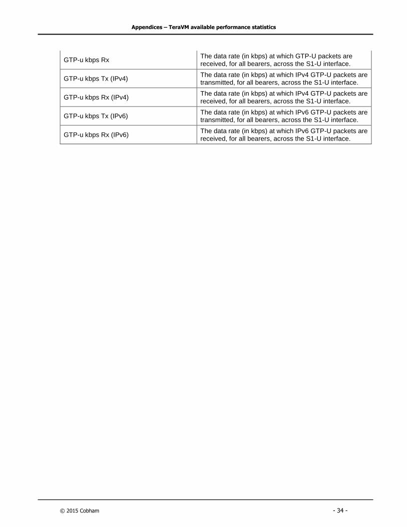
GTP-u kbps Tx The data rate (in kbps) at which GTP-U packets are transmitted, for all bearers, across the S1-U interface.
Appendices – TeraVM available performance statistics
© 2015 Cobham - 34 -
GTP-u kbps Rx The data rate (in kbps) at which GTP-U packets are received, for all bearers, across the S1-U interface.
GTP-u kbps Tx (IPv4) The data rate (in kbps) at which IPv4 GTP-U packets are transmitted, for all bearers, across the S1-U interface.
GTP-u kbps Rx (IPv4) The data rate (in kbps) at which IPv4 GTP-U packets are received, for all bearers, across the S1-U interface.
GTP-u kbps Tx (IPv6) The data rate (in kbps) at which IPv6 GTP-U packets are transmitted, for all bearers, across the S1-U interface.
GTP-u kbps Rx (IPv6) The data rate (in kbps) at which IPv6 GTP-U packets are received, for all bearers, across the S1-U interface.

Appendices – TeraVM available performance statistics
© 2015 Cobham - 35 -
6.2 TeraVM sample application statistics
TeraVM’s per flow architecture provides performance measurements for each and every
emulated application, below are sample statistics for voice call on a per bearer basis.
VoIP UA Application Item Description
UA In RTP Bits/sec The number of RTP bits/second received in by this UA.
UA Out RTP Bits/sec The number of RTP bits/second sent out by this UA.
UA In RTP Packets/sec The number of RTP packets/second received in by this UA.
UA Out RTP Packets/sec The number of RTP packets/second sent out by this UA.
UA RTP Out of Sequence Packets The number of packets out of sequence sent out by this UA.
UA RTP Dropped Packets The number of packets dropped by this UA.
UA Duplicate RTP Packets The number of duplicate packets received in by this UA.
UA Out Calls Attempted The number of calls out attempted by this UA.
UA Out Calls Established The number of calls established by this UA.
UA Out Calls Rejected The number of calls rejected by this UA.
UA In Calls Attempted The number of incoming calls that this UA attempted to receive.
UA In Calls Established The number of incoming calls established by this UA.
UA In Calls Rejected The number of incoming calls rejected by this UA.
UA Calls Errored The number of calls with errors logged by this UA.
UA SIP Out Messages The number of SIP messages sent out by this UA.
UA SIP Messages Resent The number of SIP messages resent out by this UA.
UA SIP In Messages The number of SIP messages received by this UA.
UA In RTCP Packets The number of RTCP packets received in by this UA.
UA Out RTCP Packets The number of RTCP packets sent out by this UA
UA Registrations Attempted The number of registrations attempted by this UA.
UA Registrations Successful The number of successful registrations by this UA.
UA Registrations Rejected The number of registrations rejected by this UA.
UA Registrations Errored The number of registrations with errors logged by this UA.
Appendices – TeraVM available performance statistics
© 2015 Cobham - 36 -
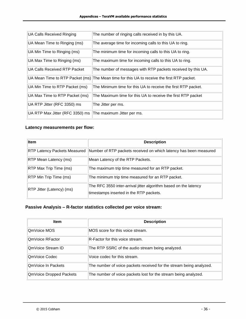
UA Calls Received Ringing The number of ringing calls received in by this UA.
UA Mean Time to Ringing (ms) The average time for incoming calls to this UA to ring.
UA Min Time to Ringing (ms) The minimum time for incoming calls to this UA to ring.
UA Max Time to Ringing (ms) The maximum time for incoming calls to this UA to ring.
UA Calls Received RTP Packet The number of messages with RTP packets received by this UA.
UA Mean Time to RTP Packet (ms) The Mean time for this UA to receive the first RTP packet.
UA Min Time to RTP Packet (ms) The Minimum time for this UA to receive the first RTP packet.
UA Max Time to RTP Packet (ms) The Maximum time for this UA to receive the first RTP packet
UA RTP Jitter (RFC 3350) ms The Jitter per ms.
UA RTP Max Jitter (RFC 3350) ms The maximum Jitter per ms.
Latency measurements per flow:
Item Description
RTP Latency Packets Measured Number of RTP packets received on which latency has been measured
RTP Mean Latency (ms) Mean Latency of the RTP Packets.
RTP Max Trip Time (ms) The maximum trip time measured for an RTP packet.
RTP Min Trip Time (ms) The minimum trip time measured for an RTP packet.
RTP Jitter (Latency) (ms) The RFC 3550 inter-arrival jitter algorithm based on the latency
timestamps inserted in the RTP packets.
Passive Analysis – R-factor statistics collected per voice stream:
Item Description
QmVoice MOS MOS score for this voice stream.
QmVoice RFactor R-Factor for this voice stream.
QmVoice Stream ID The RTP SSRC of the audio stream being analyzed.
QmVoice Codec Voice codec for this stream.
QmVoice In Packets The number of voice packets received for the stream being analyzed.
QmVoice Dropped Packets The number of voice packets lost for the stream being analyzed.
Appendices – TeraVM available performance statistics
© 2015 Cobham - 37 -
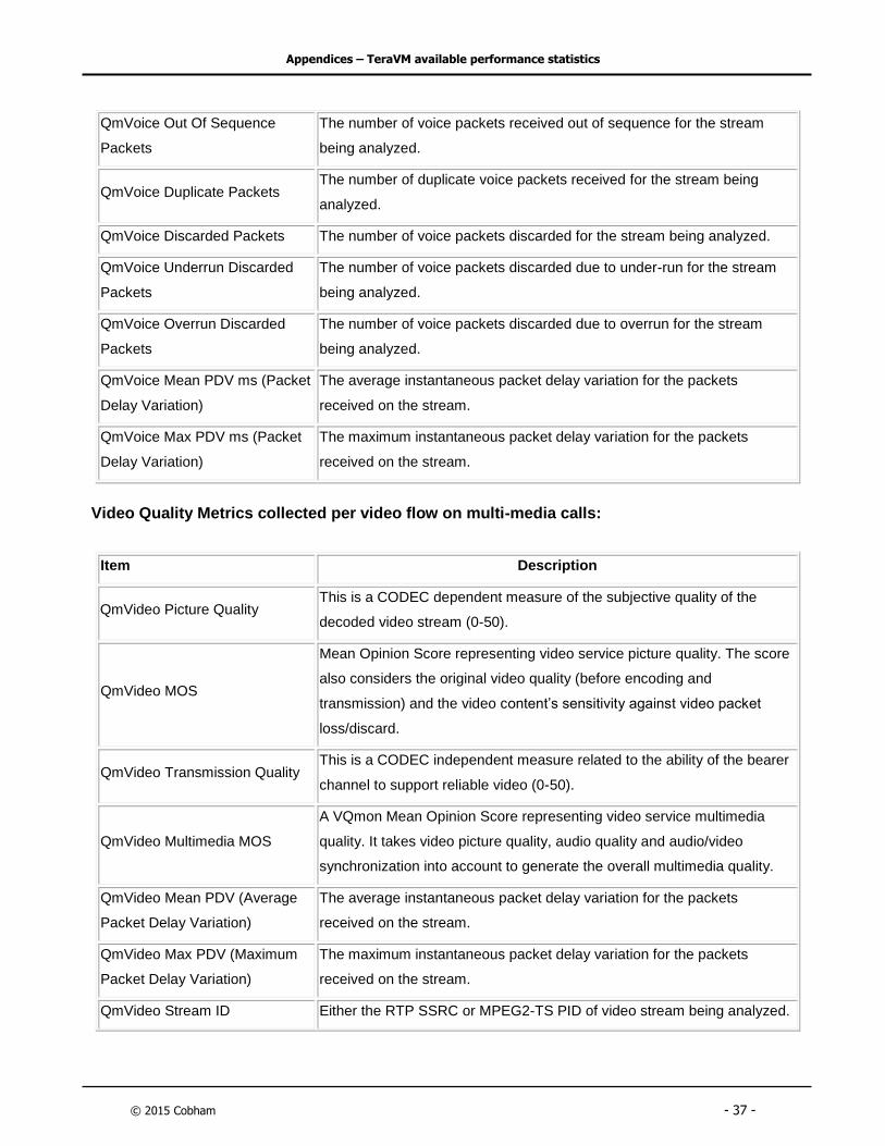
QmVoice Out Of Sequence
Packets
The number of voice packets received out of sequence for the stream
being analyzed.
QmVoice Duplicate Packets The number of duplicate voice packets received for the stream being
analyzed.
QmVoice Discarded Packets The number of voice packets discarded for the stream being analyzed.
QmVoice Underrun Discarded
Packets
The number of voice packets discarded due to under-run for the stream
being analyzed.
QmVoice Overrun Discarded
Packets
The number of voice packets discarded due to overrun for the stream
being analyzed.
QmVoice Mean PDV ms (Packet
Delay Variation)
The average instantaneous packet delay variation for the packets
received on the stream.
QmVoice Max PDV ms (Packet
Delay Variation)
The maximum instantaneous packet delay variation for the packets
received on the stream.
Video Quality Metrics collected per video flow on multi-media calls:
Item Description
QmVideo Picture Quality This is a CODEC dependent measure of the subjective quality of the
decoded video stream (0-50).
QmVideo MOS
Mean Opinion Score representing video service picture quality. The score
also considers the original video quality (before encoding and
transmission) and the video content’s sensitivity against video packet
loss/discard.
QmVideo Transmission Quality This is a CODEC independent measure related to the ability of the bearer
channel to support reliable video (0-50).
QmVideo Multimedia MOS
A VQmon Mean Opinion Score representing video service multimedia
quality. It takes video picture quality, audio quality and audio/video
synchronization into account to generate the overall multimedia quality.
QmVideo Mean PDV (Average
Packet Delay Variation)
The average instantaneous packet delay variation for the packets
received on the stream.
QmVideo Max PDV (Maximum
Packet Delay Variation)
The maximum instantaneous packet delay variation for the packets
received on the stream.
QmVideo Stream ID Either the RTP SSRC or MPEG2-TS PID of video stream being analyzed.

Appendices – TeraVM available performance statistics
© 2015 Cobham - 38 -
QmVideo Codec Video codec for this stream.
QmVideo In Packets The number of video packets received for the stream being analyzed.
QmVideo Out Of Sequence
Packets
The number of video packets received out of sequence for the stream
being analyzed.
QmVideo Dropped Packets The number of video packets lost for the stream being analyzed.
QmVideo Discarded Packets The number of video packets discarded for the stream being analyzed.
QmVideo Underrun Discarded
Packets
The number of video packets discarded due to under-run for the stream
being analyzed
QmVideo Overrun Discarded
Packets
The number of video packets discarded due to overrun for the stream
being analyzed.
QmVideo Duplicate Packets The number of duplicate video packets received for the stream being
analyzed.
QmVideo In I-Frames The number of I-frames received without impairments due to packet loss
and/or discards of the frame itself for this stream.
QmVideo Impaired I-Frames The number of I-frames impaired due to packet loss and/or discards for
this stream.
QmVideo In P-Frames The number of P-frames received without impairments due to packet loss
and/or discards of the frame itself for this stream.
QmVideo Impaired P-Frames
The number of P-frames impaired due to packet loss and/or discards for
this stream. This does not include frames impaired due to error
propagation through temporal reference.
QmVideo In B-Frames The number of B-frames received without impairments due to packet loss
and/or discards of the frame itself.
QmVideo Impaired B-Frames
The number of B-frames impaired due to packet loss and/or discards for
this stream. This does not include frames impaired due to error
propagation through temporal reference.
QmVideo Frames/s The frame rate of the video stream in frames per second.
QmVideo Frame Width The width of the video frame in pixels.
QmVideo Frame Height The height of the video frame in pixels.

Appendices – TeraVM available performance statistics
© 2015 Cobham - 39 -
QmVideo GoP Length The Group of Picture length for the video stream. The GOP length is the
number of frames between two full images (I-Frames).
QmVideo GoP Type The Group of Picture type for the video stream.
Video metrics for MPEG2-TS transport enabled calls:
Item Description
QmMp2ts TS_sync_loss TR 101 290 MPEG2-TS number of occurrences of transport stream sync
loss for this video elementary stream.
QmMp2ts Sync_byte_error TR 101 290 MPEG2-TS number of occurrences of sync byte error for this
video elementary stream.
QmMp2ts
Continuity_count_error
TR 101 290 MPEG2-TS number of occurrences of continuity counter error
for this video elementary stream.
QmMp2ts Transport_error TR 101 290 MPEG2-TS number of occurrences of packet with transport
error bit set for this video elementary stream.
QmMp2ts PCR_repetition_error
TR 101 290 MPEG2-TS number of occurrences of time interval between
two consecutive PCR values more than 40 milliseconds for this video
elementary stream.
QmMp2ts
PCR_discontinuity_indicator_err
or
TR 101 290 MPEG2-TS number of occurrences of the difference between
two consecutive PCR values is outside the range of 0 to 100 milliseconds
for this video elementary stream.
QmMp2ts PTS_error
TR 101 290 MPEG2-TS Number of occurrences of the presentation
timestamp repetition period is more than 700 milliseconds for this video
elementary stream.
6.3 Dual Hosted VoIP Application Results
The statistics gathered for a Dual Hosted VoIP UA are the same as those gathered for
a (single host) VoIP UA. However, as the Dual Hosted VoIP UA can register or initiate
calls using an IPv4 or an IPv6 external SIP Proxy, no differentiations will be made
between the registration and call initiation results displayed for IPv4 and for IPv6.

Appendices – TeraVM available performance statistics
© 2015 Cobham - 40 -
6.4 Supported Voice Codecs
The following are a list of pre-configured voice codecs supported by TeraVM:
1. AMR-WB
2. Cisco E20-C20 MP4A
3. H.264 128x96px 100 kbits/s
4. AMR-NB
5. CTS H.264
6. iLBC 15.2 kbits/s
7. Cisco E20-C20 H.264
8. CTS AAC-LD
9. H.264 176x144px 350 kbits/s
10. H.264 128x96px 300 kbits/s
11. H.264 320x240px 900 kbits/s
12. H.264 320x240px 600 kbits/s
13. GSM
14. G.722 (ACELP)
15. G.728
16. G.729
17. iLBC 13.33 kbits/s
18. G.711a (PCMA)
19. G.711u (PCM)
20. G.723 6.3 kbits/s (MP-MLQ)
21. G.723 5.3 kbits/s (MP-MLQ)

Appendices – TeraVM available performance statistics
© 2015 Cobham - 41 -
6.5 Supported Video/Audio and Voice Codecs
TeraVM supports a number of pre-configured codecs, in addition TeraVM supports a
configurable CODEC template with flexible Sample Period, Frame Size and Packet Rate.
6.5.1 Video/Audio Codecs
The following are a list of pre-configured video/audio codecs supported by TeraVM, note
TeraVM supports concurrent measurement of both the video and audio in real-time:
Video Codec Audio Codec
JPEG MPEG-1 Layer 1
MPEG MPEG-1 Layer 2
H.261 MPEG-1 Layer 3
H.263 MPEG-2 AAC
H.263+ AC-3
H.264 MPEG-4 AAC
MPEG-4 MPEG-4 Low Delay AAC
VC-1 MPEG-4 High Efficiency
MPEG2TS

Performance validation for the mobile core
As we are always seeking to improve our products, the information in this document gives only a general indication of the produc t
capacity, performance and suitability, none of which shall form part of any contract. We reserve the right to make design changes
without notice. All trademarks are acknowledged. © Cobham 2015.
The most important thing we build is trust
For further information please contact:
Cobham Wireless
Ireland: +353-1-236-7002
USA: +1 408-385-7630