rotorcorp.comrotorcorp.com/wp-content/uploads/2011/10/r66_mm_powerplant.pdf25 oct 2010 r66...
TRANSCRIPT

25 OCT 2010 R66 Maintenance Manual Chapter 71 Powerplant Page 71.i
CHAPTER 71
POWERPLANT
Section Title Page
71-00 Description . . . . . . . . . . . . . . . . . . . . . . . . . . . . . . . . . . . . . . . . 71.1
71-10 Engine . . . . . . . . . . . . . . . . . . . . . . . . . . . . . . . . . . . . . . . . . . . 71.3
71-20 Induction . . . . . . . . . . . . . . . . . . . . . . . . . . . . . . . . . . . . . . . . . 71.7
71-21 Air Filter Assembly . . . . . . . . . . . . . . . . . . . . . . . . . . 71.7
71-22 Cage Assembly . . . . . . . . . . . . . . . . . . . . . . . . . . . . . 71.8
71-23 Engine Inlet Bellmouth . . . . . . . . . . . . . . . . . . . . . . . . 71.8
71-30 Exhaust Weldment . . . . . . . . . . . . . . . . . . . . . . . . . . . . . . . . . . 71.11
71-40 Accessories . . . . . . . . . . . . . . . . . . . . . . . . . . . . . . . . . . . . . . . 71.12
71-41 Starter-Generator . . . . . . . . . . . . . . . . . . . . . . . . . . . 71.12
71-42 Generator Control Unit (GCU) . . . . . . . . . . . . . . . . . . . 71.12
71-43 Engine Monitoring Unit (EMU) . . . . . . . . . . . . . . . . . . . 71.13

Intentionally Blank
Page 71.ii Chapter 71 Powerplant R66 Maintenance Manual 25 OCT 2010
CHAPTER 71
POWERPLANT
71-00 Description
This chapter includes instructions for the removal and installation of the aircraft engine and the engine induction, cooling, and exhaust systems. Refer to RR300 Series Operation and Maintenance Manual (OMM) and engine component manufacturer’s maintenance publications for product specific inspection, repair, and maintenance procedures.
R66 helicopters are powered by one Rolls-Royce model 250-C300/A1 free-turbine turboshaft engine with a normal cruise power output rating of 220 shaft horsepower (shp), a maximum continuous horsepower (MCP) rating of 240 shp, and a 5-minute takeoff rating of 300 shp. The engine is equipped with an ignition exciter, igniter, starter-generator, two tachometer senders, and additional powerplant instrument senders.
A direct drive, squirrel cage cooling fan is mounted to the shaft forward of the long tail rotor drive shaft and supplies cooling air to the engine and gearbox oil coolers.
Induction air enters through multiple openings in the upper fuselage cowlings and flows into a plenum forward of the firewall. The plenum contains a radial-flow air filter at the engine compressor inlet.
If the air filter becomes blocked, spring-loaded doors at the front of the filter housing open allowing unfiltered air to the engine. A segment on the annunciator panel notifies the pilot that filter bypass is occurring.
Periodically performing power assurance checks and monitoring trend may provide early indication of engine deterioration or air filter blockage. Maintenance actions such as air filter replacement and compressor rinse should be performed if aircraft fails power assurance check.
25 OCT 2010 R66 Maintenance Manual Chapter 71 Powerplant Page 71.1

Page 71.2 Chapter 71 Powerplant R66 Maintenance Manual 25 OCT 2010
FIGURE 71-1 ENGINE - RIGHT SIDE
71-10 Engine
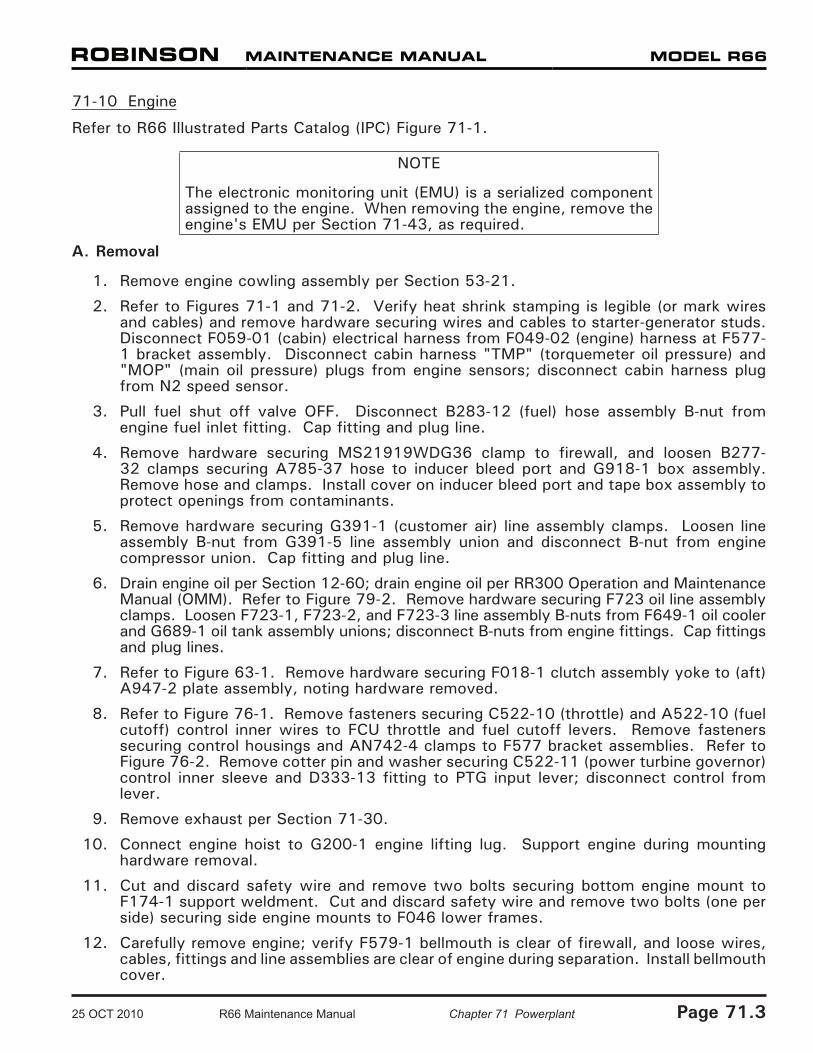
Refer to R66 Illustrated Parts Catalog (IPC) Figure 71-1.
NOTE
The electronic monitoring unit (EMU) is a serialized component assigned to the engine. When removing the engine, remove the engine's EMU per Section 71-43, as required.
A. Removal
1. Remove engine cowling assembly per Section 53-21.
2. Refer to Figures 71-1 and 71-2. Verify heat shrink stamping is legible (or mark wires and cables) and remove hardware securing wires and cables to starter-generator studs. Disconnect F059-01 (cabin) electrical harness from F049-02 (engine) harness at F577-1 bracket assembly. Disconnect cabin harness "TMP" (torquemeter oil pressure) and "MOP" (main oil pressure) plugs from engine sensors; disconnect cabin harness plug from N2 speed sensor.
3. Pull fuel shut off valve OFF. Disconnect B283-12 (fuel) hose assembly B-nut from engine fuel inlet fitting. Cap fitting and plug line.
4. Remove hardware securing MS21919WDG36 clamp to firewall, and loosen B277-32 clamps securing A785-37 hose to inducer bleed port and G918-1 box assembly. Remove hose and clamps. Install cover on inducer bleed port and tape box assembly to protect openings from contaminants.
5. Remove hardware securing G391-1 (customer air) line assembly clamps. Loosen line assembly B-nut from G391-5 line assembly union and disconnect B-nut from engine compressor union. Cap fitting and plug line.
6. Drain engine oil per Section 12-60; drain engine oil per RR300 Operation and Maintenance Manual (OMM). Refer to Figure 79-2. Remove hardware securing F723 oil line assembly clamps. Loosen F723-1, F723-2, and F723-3 line assembly B-nuts from F649-1 oil cooler and G689-1 oil tank assembly unions; disconnect B-nuts from engine fittings. Cap fittings and plug lines.
7. Refer to Figure 63-1. Remove hardware securing F018-1 clutch assembly yoke to (aft) A947-2 plate assembly, noting hardware removed.
8. Refer to Figure 76-1. Remove fasteners securing C522-10 (throttle) and A522-10 (fuel cutoff) control inner wires to FCU throttle and fuel cutoff levers. Remove fasteners securing control housings and AN742-4 clamps to F577 bracket assemblies. Refer to Figure 76-2. Remove cotter pin and washer securing C522-11 (power turbine governor) control inner sleeve and D333-13 fitting to PTG input lever; disconnect control from lever.
9. Remove exhaust per Section 71-30.
10. Connect engine hoist to G200-1 engine lifting lug. Support engine during mounting hardware removal.
11. Cut and discard safety wire and remove two bolts securing bottom engine mount to F174-1 support weldment. Cut and discard safety wire and remove two bolts (one per side) securing side engine mounts to F046 lower frames.
12. Carefully remove engine; verify F579-1 bellmouth is clear of firewall, and loose wires, cables, fittings and line assemblies are clear of engine during separation. Install bellmouth cover.
25 OCT 2010 R66 Maintenance Manual Chapter 71 Powerplant Page 71.3

Page 71.4 Chapter 71 Powerplant R66 Maintenance Manual 25 OCT 2010
FIGURE 71-2 ENGINE - LEFT SIDE
71-10 Engine (continued)
B. Installation
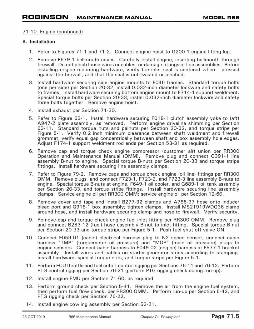
1. Refer to Figures 71-1 and 71-2. Connect engine hoist to G200-1 engine lifting lug.
2. Remove F579-1 bellmouth cover. Carefully install engine, inserting bellmouth through firewall. Do not pinch loose wires or cables, or damage fittings or line assemblies. Before installing engine mounting hardware, verify the inlet seal is centered when pressed against the firewall, and that the seal is not twisted or pinched.
3. Install hardware securing side engine mounts to F046 frames. Standard torque bolts (one per side) per Section 20-32; install 0.032-inch diameter lockwire and safety bolts to frames. Install hardware securing bottom engine mount to F714-1 support weldment. Special torque bolts per Section 20-33; install 0.032-inch diameter lockwire and safety three bolts together. Remove engine hoist.
4. Install exhaust per Section 71-30.
5. Refer to Figure 63-1. Install hardware securing F018-1 clutch assembly yoke to (aft) A947-2 plate assembly, as removed. Perform engine driveline shimming per Section 63-11. Standard torque nuts and palnuts per Section 20-32, and torque stripe per Figure 5-1. Verify 0.2 inch minimum clearance between shaft weldment and firewall grommet; verify equal gap concentrically between shaft and box assembly hole edges. Adjust F174-1 support weldment rod ends per Section 53-31 as required.
6. Remove cap and torque check engine compressor (customer air) union per RR300 Operation and Maintenance Manual (OMM). Remove plug and connect G391-1 line assembly B-nut to engine. Special torque B-nuts per Section 20-33 and torque stripe fittings. Install hardware securing line assembly clamps.
7. Refer to Figure 79-2. Remove caps and torque check engine (oil line) fittings per RR300 OMM. Remove plugs and connect F723-1, F723-2, and F723-3 line assembly B-nuts to engine. Special torque B-nuts at engine, F649-1 oil cooler, and G689-1 oil tank assembly per Section 20-33, and torque stripe fittings. Install hardware securing line assembly clamps. Service engine oil per RR300 OMM; service engine oil per Section 12-60.
8. Remove cover and tape and install B277-32 clamps and A785-37 hose onto inducer bleed port and G918-1 box assembly; tighten clamps. Install MS21919WDG36 clamp around hose, and install hardware securing clamp and hose to firewall. Verify security.
9. Remove cap and torque check engine fuel inlet fitting per RR300 OMM. Remove plug and connect B283-12 (fuel) hose assembly B-nut to inlet fitting. Special torque B-nut per Section 20-33 and torque stripe per Figure 5-1. Push fuel shut off valve ON.
10. Connect F059-01 (cabin) electrical harness plug to N2 speed sensor; connect cabin harness "TMP" (torquemeter oil pressure) and "MOP" (main oil pressure) plugs to engine sensors. Connect cabin harness to F049-02 (engine) harness at F577-1 bracket assembly. Install wires and cables on starter-generator studs according to stamping. Install hardware, special torque nuts, and torque stripe per Figure 5-1.
11. Perform FCU throttle and fuel cutoff control rigging per Sections 76-11 and 76-12. Perform PTG control rigging per Section 76-21 (perform PTG rigging check during run-up).
12. Install engine EMU per Section 71-60, as required.
13. Perform ground check per Section 5-41. Remove the air from the engine fuel system, then perform fuel flow check, per RR300 OMM. Perform run-up per Section 5-42, and PTG rigging check per Section 76-22.
14. Install engine cowling assembly per Section 53-21.
25 OCT 2010 R66 Maintenance Manual Chapter 71 Powerplant Page 71.5
Page 71.6 Chapter 71 Powerplant R66 Maintenance Manual 25 OCT 2010
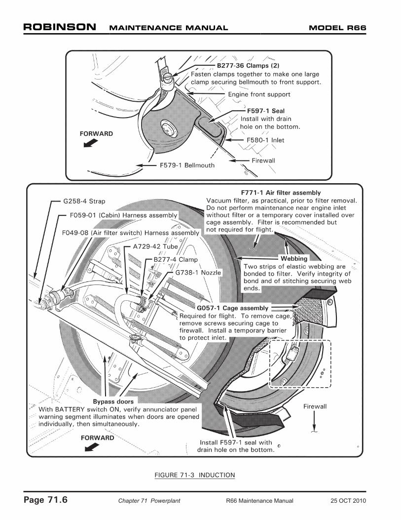
FIGURE 71-3 INDUCTION

71-20 Induction
CAUTION
Never operate engine without G057-1 cage assembly installed. F771-1 filter assembly not required for flight.
CAUTION
Do not perform maintenance near engine inlet without either a filter assembly or a temporary cover installed on G057-1 cage assembly. Contact Rolls-Royce Customer Support if foreign objects enter inlet.
71-21 Air Filter Assembly
Refer to R66 Illustrated Parts Catalog (IPC) Figure 71-3.
NOTE
Replace F771-1 air filter assembly every 100 hours, or earlier if filter is soiled from severe environment operation.
A. Removal
1. Remove tailcone cowling assembly per Section 53-23. Open main rotor gearbox compartment access door.
2. Refer to Figure 71-3. Vacuum exterior of F771-1 filter assembly.
3. Disconnect F049-08 (air filter switch) electrical harness plug from F059-01 (cabin) harness at G258-4 strap.
4. Loosen B277-4 clamp securing A729-42 tube to G738-1 nozzle; pull tube off of nozzle.
5. Pull filter forward off of G057-1 cage assembly.
B. Installation
1. Refer to Figure 71-3. Pull F771-1 filter assembly aft over G057-1 cage assembly.
2. Install B277-4 clamp and A729-4 tube onto G738-1 nozzle and tighten clamp. Verify security.
3. Connect F049-08 (air filter switch) electrical harness plug to F059-01 (cabin) harness at G258-4 strap.
4. Turn BATTERY switch ON. To test air bypass warning circuit, verify annunciator panel warning segment illuminates when bypass doors are opened individually, then simultaneously. Turn BATTERY switch OFF.
5. Install tailcone cowling assembly per Section 53-23. Close main rotor gearbox compartment access door.
6. Perform compressor rinse per RR300 Series Operation and Maintenance Manual (OMM).
25 OCT 2010 R66 Maintenance Manual Chapter 71 Powerplant Page 71.7
71-22 Cage Assembly
Refer to R66 Illustrated Parts Catalog (IPC) Figure 71-3.
A. Removal
1. Remove tail rotor drive shaft weldment per Section 65-10.
2. Remove air filter assembly per Section 71-21.
3. Refer to Figure 71-3. Remove hardware securing G057-1 cage assembly to firewall and remove cage. Install suitable barrier to prevent foreign objects from entering engine inlet.
B. Installation
1. Refer to Figure 71-3. Remove barrier, position G057-1 cage assembly against firewall, and install hardware securing cage to firewall. Verify security.
2. Install air filter assembly per Section 71-21.
3. Install tail rotor drive shaft weldment per Section 65-10.
71-23 Engine Inlet Bellmouth
Refer to R66 Illustrated Parts Catalog (IPC) Figure 71-5.
A. Removal
1. Remove engine per Section 75-10.
2. Refer to Figure 71-3. Remove F579-1 bellmouth cover and loosen B277-36 clamps securing bellmouth to engine front support. Remove bellmouth and clamps.
3. Remove hardware securing F597-1 seal and F580-1 inlet to engine front support. Remove seal and inlet. Install cover over front support.
B. Installation
1. Refer to Figure 71-3. Remove engine front support cover, install F580-1 inlet and F597-1 seal (drain hole on bottom) on front support, and install hardware. Verify security.
2. Install B277-36 clamps and F579-1 bellmouth over front support flange, and tighten clamps. Verify security.
3. Install engine per Section 71-10.
Page 71.8 Chapter 71 Powerplant R66 Maintenance Manual 25 OCT 2010
Intentionally Blank
25 OCT 2010 R66 Maintenance Manual Chapter 71 Powerplant Page 71.9

FIGURE 71-4 EXHAUST
Page 71.10 Chapter 71 Powerplant R66 Maintenance Manual 25 OCT 2010
71-30 Exhaust Weldment
Refer to R66 Illustrated Parts Catalog (IPC) Figure 71-7.
A. Removal
1. Remove engine cowling assembly per Section 53-21.
2. Refer to Figure 71-4. Remove hardware securing F173-1 struts to F169-1 exhaust weldment and engine, and remove struts.
3. Loosen two B277-8 clamps securing A785-36 (accessory gearbox vent) hose to exhaust; pull hose off of exhaust weldment.
4. Remove three fasteners securing exhaust weldment to engine exhaust collector. Carefully lift exhaust weldment up and off of F169-2 base flange, and remove exhaust weldment.
5. As required, remove hardware securing base and F577-5 bracket to exhaust collector and remove base. Install exhaust collector cover.
B. Installation
1. Refer to Figure 71-4. If F169-2 base is installed, proceed to step 3. Verify base and engine exhaust collector mating surfaces are clean and dry, and lay 0.25 inch bead 7020-3 ceramic putty on top of exhaust collector flange.
2. Position F169-2 base and F577-5 bracket on exhaust collector and install hardware. Verify security. Remove excess putty.
3. Position F169-1 exhaust weldment on base and install three fasteners securing exhaust weldment to exhaust collector.
4. Install hardware securing F173-1 struts to exhaust weldment and engine. Special torque engine tee-bolts per Section 20-33.
5. Install engine cowling assembly per Section 53-21.
25 OCT 2010 R66 Maintenance Manual Chapter 71 Powerplant Page 71.11
Page 71.12 Chapter 71 Powerplant R66 Maintenance Manual 25 OCT 2010
71-40 Accessories
71-41 Starter-Generator
Refer to R66 Illustrated Parts Catalog (IPC) Figure 71-9.
A. Removal
1. Remove engine cowling assembly per Section 53-21.
2. Refer to Figure 71-1. Verify heat shrink stamping is legible (or mark wires and cables) and remove hardware securing wires and cables to starter-generator studs.
3. Remove starter-generator per RR300 Series Operation and Maintenance Manual (OMM).
B. Installation
1. Install starter-generator per RR300 Series Operation and Maintenance Manual (OMM).
2. Refer to Figure 71-1. Install wires and cables on starter-generator studs according to stamping. Install hardware, special torque nuts, and torque stripe per Figure 5-1.
3. Install engine cowling assembly per Section 53-21.
71-42 Generator Control Unit (GCU)
Refer to R66 Illustrated Parts Catalog (IPC) Figure 71-11.
A. Removal
1. Open baggage compartment door. Remove hardware securing G248-1 cover to inner compartment and remove cover.
2. Disconnect F049-03 (GCU) electrical harness plug from GCU. Remove mounting hardware, and remove GCU. Cap receptacles.
B. Installation
1. Open baggage compartment door. Position GCU on inner compartment shelf and install mounting hardware. Verify security.
2. Remove caps and connect F049-03 (GCU) electrical harness plug to GCU. Install hardware securing G248-1 cover to inner compartment. Close and secure baggage door.
71-43 Engine Monitoring Unit (EMU)
Refer to R66 Illustrated Parts Catalog (IPC) Figure 71-13.
NOTE
The electronic monitoring unit (EMU) is a serialized component assigned to the engine. When removing the engine, remove the engine's EMU per Section 71-43, as required.
A. Removal
1. Remove hardware securing F003-4 (RH) seat back assembly to cabin.
2. Disconnect F059-01 (cabin) electrical harness "EMU" plug and F049-07 (USB) harness plug from EMU.
3. Remove hardware securing EMU to bulkhead and remove EMU. Cap receptacles.
B. Installation
1. Remove caps, position EMU on bulkhead, and install hardware. Verify security.
2. Connect F059-01 (cabin) electrical harness "EMU" plug and F049-07 (USB) harness plug to EMU.
3. Turn BATTERY switch ON. After 10 seconds press annunciator panel test button; verify EMU amber warning segment illuminates, and is solid, indicating normal EMU operation. (See R66 Pilot's Operating Handbook Section 7 for complete description.) Turn BATTERY switch OFF.
4. Install hardware securing F003-4 (RH) seat back assembly to cabin.
C. Downloading EMU Data
NOTE
An EMU USB receptacle is located inside the aft right seat baggage compartment, on the underside of the aft ledge. Use a flashlight and mirror when inserting USB cable into receptacle.
Download summary or diagnostic data per RR300 Series Operation and Maintenance Manual (OMM).
25 OCT 2010 R66 Maintenance Manual Chapter 71 Powerplant Page 71.13

Intentionally Blank
Page 71.14 Chapter 71 Powerplant R66 Maintenance Manual 25 OCT 2010