ocle docle report to the joint committee on space astronomy
TRANSCRIPT

OCLE DOCLEOCLE DOCLEReport to the Joint Committee on Space AstronomyReport to the Joint Committee on Space Astronomy

MMMB RFP Response
CSA call in Fall 2007
Concept for Science observations using MMMB
Proposal lead by Project Manager at COMDEV
sub-contracted Science Requirements to HIA
Concept Study Report submitted in Feb. 2009
Primary Science GOALPrimary Science GOALProbe the radial extent and size distribution of the Outer Solar SystemProbe the radial extent and size distribution of the Outer Solar System

Influence of Stellar Nursery Densityon location of Inner Edge of Inner-Oort Cloud
Sed
na
Sed
na
200
0 C
R105
200
0 C
R105
200
4 V
N112
200
4 V
N112

The Experiment
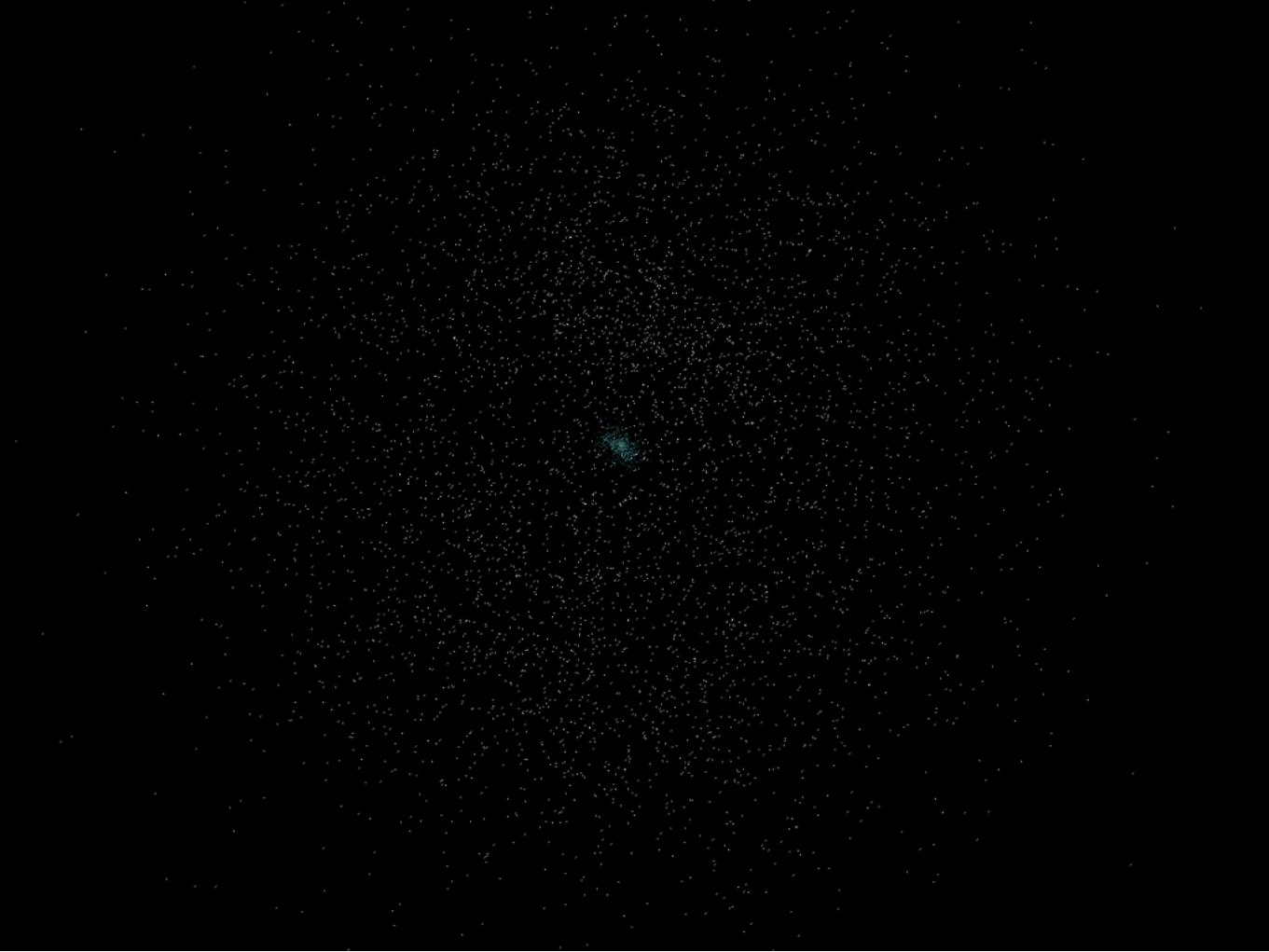
Monitor background stars at sufficiently cadence detect serendipitous stellar occultation and determine the sky density of small bodies
Simultaneously probes the entire line of sight:Near Earth Objects, Main Belt Asteroids,Kuiper Belt Objects, Inner and Outer Oort Cloud Objects,Other?

Diffraction events
When path difference from one side of source to the observer is about 1/2 wavelength
for KBOs (2000m) and optical light (600 nm) this occurs when the distance to the observer is ~ 40 AU (6x10¹² m)
~ 2 km size objects blocking light from a point source create a circular diffraction ring.
The size of the diffraction ring is 2-3 km at the distance of the Earth and the observer passes through the ring at ~30 km/s => events last 0.1 s

QuickTime™ and aYUV420 codec decompressor
are needed to see this picture.
Animation available at www.astro.princeton.edu/~bick/research.html
Occultation Lightcurves at Various Object Sizes
3.5 Fsu = 4.4 km at 40 AU

Stars are not Point souRces

Ideal stars are Bright and compact


Operational Strategy
Point at a bright open cluster (M35 or M25), available in CVZ for ~60 days each (doubled for PVZ)Snapshot image and centroid available bright starsCentroid updates to AOCS at 4 Hz to stabilize pointingCo-add and download cluster imageTweak satellite attitude to centre the target clusterDownload continuous low-noise 40 Hz photometry (2x2 bin) on ~1000 stars to detect ~2 second occultation eventsRetarget after 60 daysRepeat

7
MMMB Specifications

6
COM DEV Proprietary Information© HER MAJESTY THE QUEEN IN RIGHT OF CANADA (2009)
Design Concept Summary
• Aluminum 30 cm diameter TMA building on JWST heritage
• Imaging onto back-illuminated CMOS silicon detector array.
• 11.25 MPix at 1 arcsec sampling
• 30-40 Hz 2x2 pixel binned photometry at <10 electrons read noise on 1000 stars
• Power (30 W), mass (27 kg), and volume (57 x 49 x 36 cm) all in range of CSA Multi-Mission-Microsat Bus

11
COM DEV Proprietary Information© HER MAJESTY THE QUEEN IN RIGHT OF CANADA (2009)
Payload Design Concept Review
Design Targets:• KISS microsat philosophy to minimize risk within requirements• Simple operational scenario to simplify electronics and software.
– Minimize onboard processing • Optical design to:
– Maximize telescope aperture within MMMB mass and volume allocations– Maximize field of view
• Select detector to:– Achieve <4 electron, 40 Hz sampling rate– Maintain MMMB power allocation– Provide spatial sampling to:
• Oversample PSF for accurate centroiding inputs to AOCS• Minimize impact of read noise on photometry• Avoid confusion crowding of targets

12
COM DEV Proprietary Information© HER MAJESTY THE QUEEN IN RIGHT OF CANADA (2009)
Mechanical Design – General Considerations
• Single-piece enclosure houses all optical elements and detector– Ensures stable mechanical environment– Simplifies alignment– Maintains alignment over the temperature range
• Aluminum has been baselined as the material of choice– Heritage in TMA manufacture, both for structure and for optical
elements– Good thermal conductivity ensures stability of the TMA

13
COM DEV Proprietary Information© HER MAJESTY THE QUEEN IN RIGHT OF CANADA (2009)
Mechanical Design - Structural
• TMA enclosure consists of a milled box manufactured from a single piece
• Bolts to the bus structure via flexured legs (not pictured)– Structure is independent of the Spacecraft’s distortions over time

14
COM DEV Proprietary Information© HER MAJESTY THE QUEEN IN RIGHT OF CANADA (2009)
Mechanical Design - Thermal
• Thermal environment: –30º to +40º C (relatively benign)• Detector’s high frame rate makes the Instrument insensitive
to thermal variations• Thermal gradients will be minimized, thermal paths will be
optimized in the design• Passive cooling (i.e. thermal control coatings) is sufficient,
cooling systems are not necessary• EU will not contribute to the thermal environment of the
optics.
15
COM DEV Proprietary Information© HER MAJESTY THE QUEEN IN RIGHT OF CANADA (2009)
Mechanical Design - Optics
• Relative positions of mounting surfaces will be maintained during machining
• Mirrors are a significant part of the Instrument mass, and they will be weight-relieved
• Mirrors will be joined to the Enclosure via flexured tabs, diamond-turned and post-polished
• Stray light and contamination may be controlled through the use of a deployable dust-cover / external baffle
• Stray light will be excluded by the TMA design, and by the use of black coatings where warranted

17
COM DEV Proprietary Information© HER MAJESTY THE QUEEN IN RIGHT OF CANADA (2009)
Optical Design
• f/5.78; 300 mm TMA• FOV 0.4 x 2.0 degrees• Deployable baffles TBC• Lightweighted Aluminum• 400-750 nm waveband• ~2.5 nm RMS surface
roughness (post-polished plated aluminum)
• ~45 nm WFE

18
COM DEV Proprietary Information© HER MAJESTY THE QUEEN IN RIGHT OF CANADA (2009)
Optical Performance

19
COM DEV Proprietary Information© HER MAJESTY THE QUEEN IN RIGHT OF CANADA (2009)
Detector Selection
• Array of 5 butted square detectors required for rectangular field• Target 1500 x 1500 x 8 μm area per detector• Pixel size larger than ~8 μm degrades centroiding accuracy• CMOS readout with CCD-type back-illuminated pixel design is required• Large frame CCD would require several Watts vs. 250 mW per CMOS
Parameter DALSA ESNR Sarnoff BI-CMOS Fairchild L3CIS Teledyne 4T CMOS Teledyne HyVisI
Readnoise (electrons) ~0 2-5 1.5 2.5 4
Gain noise (%) <5 0 0 0 0
Pixel size (μm) 8 8 6.5 4 40
Blue QE (%) 90 70 <40 40 90
Max Frame Rate (Hz) 40 30 120 60 900
Array Size 1500 x 1500 1024 x 1024 2048 x 2560 1032 x 768 128 x 128
Available? 16 months $1.5M Q1 2009 Now Now Q1 2009

20
COM DEV Proprietary Information© HER MAJESTY THE QUEEN IN RIGHT OF CANADA (2009)
Electronics Concept
• FPGA controller with microcomputer core (TBC).• 4 readouts per detector for 20 analog chains
– 22.5 MPix/sec/chain @ 14 bits• Perform 2 x 2 pixel photometric sums on ~1000 stars• Perform 8 x 8 pixel centroids at 4 Hz to update photometric
windows• Provide centroid telemetry at 4 Hz to AOCS• Use MMMB memory to cache photometric telemetry• 6 x RS-422 interfaces• Housekeeping telemetry provided by MMMB.• Provide 2 banks of image RAM for co-adding in secondary imaging
mode.

22
COM DEV Proprietary Information© HER MAJESTY THE QUEEN IN RIGHT OF CANADA (2009)
Power Budget
• MMMB payload power allocation is 32 W orbit average.
Subsystem Quantity Average Power (W)
Control/Imaging System 1
Detectors 5 1
FPGA Controller(s) 1-2 <3
High speed 14 bit A/D 20 <5.5
Op-amps 40 2
Power Supply 1 3
Local Volatile Memory (Imaging, 2 image buffers) 57 MB 2
RS-422 Tx/Rx interface chipset 6 0.5
Design Contingency TBD 3
Total 20
24
COM DEV Proprietary Information© HER MAJESTY THE QUEEN IN RIGHT OF CANADA (2009)
Mission Analysis
• Equatorial orbit allows continuous view of high latitude regions– Must deal with Earthshine on bright side of planet
• Polar orbit allows viewing of ecliptic regions, maximizes solar panel output– Would need to choose new targets every couple months (MOST).
• LEO is cheapest, low radiation environment and suitable for microsatellite.
• Require low drift rate active 3-axis stabilization to minimize effects of photometric response deviations in the detector.– 1 arcseconds achieved for MOST with mini-reaction wheels


27
COM DEV Proprietary Information© HER MAJESTY THE QUEEN IN RIGHT OF CANADA (2009)
Technical Risks

28
COM DEV Proprietary Information© HER MAJESTY THE QUEEN IN RIGHT OF CANADA (2009)
Payload/Mission Cost
29
COM DEV Proprietary Information© HER MAJESTY THE QUEEN IN RIGHT OF CANADA (2009)
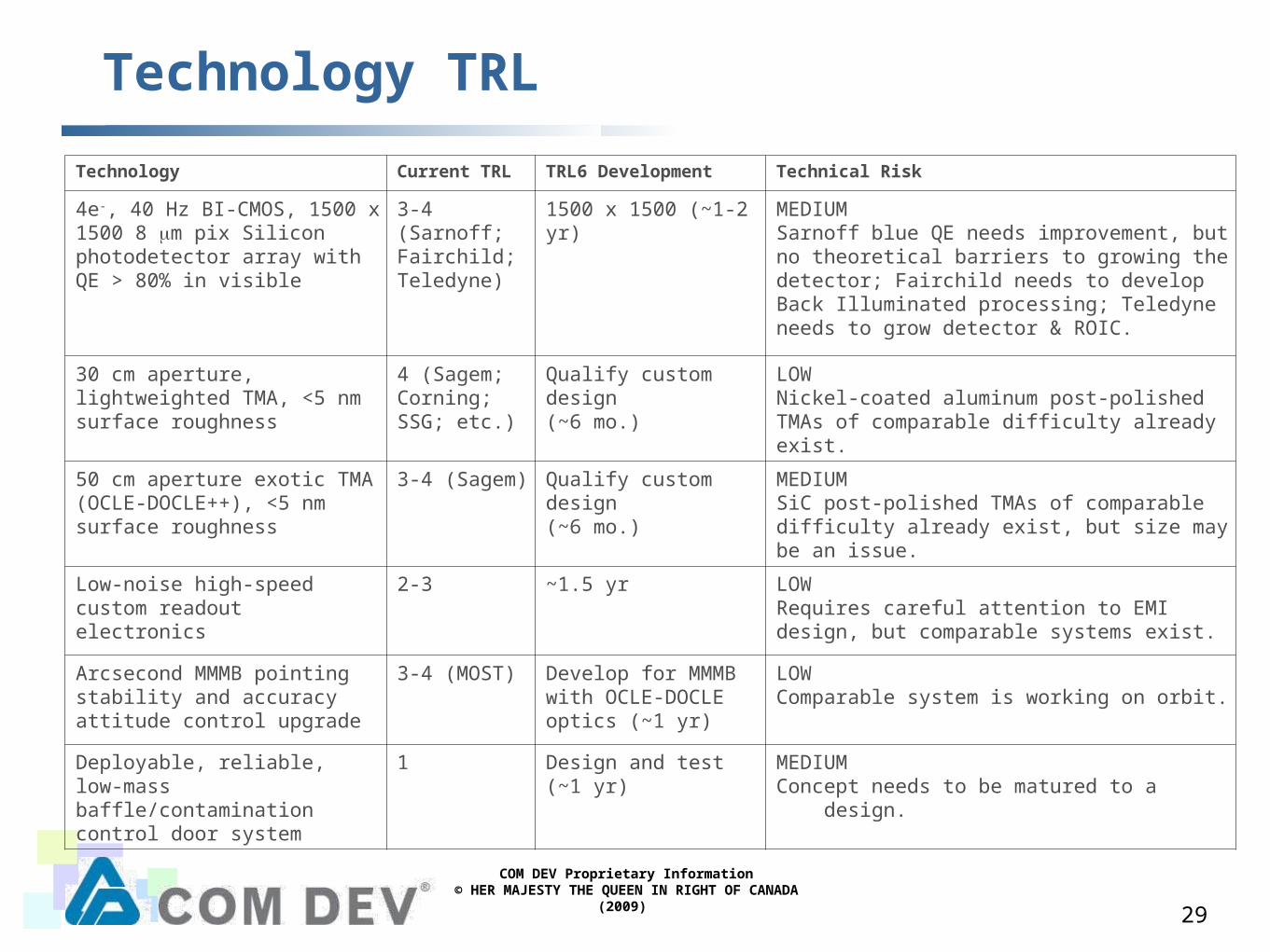
Technology TRL
Technology Current TRL TRL6 Development Technical Risk
4e-, 40 Hz BI-CMOS, 1500 x 1500 8 μm pix Silicon photodetector array with QE > 80% in visible
3-4 (Sarnoff; Fairchild; Teledyne)
1500 x 1500 (~1-2 yr) MEDIUMSarnoff blue QE needs improvement, but no theoretical barriers to growing the detector; Fairchild needs to develop Back Illuminated processing; Teledyne needs to grow detector & ROIC.
30 cm aperture, lightweighted TMA, <5 nm surface roughness
4 (Sagem; Corning; SSG; etc.)
Qualify custom design (~6 mo.)
LOWNickel-coated aluminum post-polished TMAs of comparable difficulty already exist.
50 cm aperture exotic TMA (OCLE-DOCLE++), <5 nm surface roughness
3-4 (Sagem) Qualify custom design (~6 mo.)
MEDIUMSiC post-polished TMAs of comparable difficulty already exist, but size may be an issue.
Low-noise high-speed custom readout electronics
2-3 ~1.5 yr LOWRequires careful attention to EMI design, but comparable systems exist.
Arcsecond MMMB pointing stability and accuracy attitude control upgrade
3-4 (MOST) Develop for MMMB with OCLE-DOCLE optics (~1 yr)
LOWComparable system is working on orbit.
Deployable, reliable, low-mass baffle/contamination control door system
1 Design and test (~1 yr) MEDIUMConcept needs to be matured to a design.

9
COM DEV Proprietary Information© HER MAJESTY THE QUEEN IN RIGHT OF CANADA (2009)
Next Steps
• Advanced/Phase0 study to assess requirements of potential partners and provide advanced operating concepts and updated budgets
• High-speed readout electronics breadboard for detailed assessment of BI-CMOS technology.