occurrence of high salinity fluids … of high salinity fluids associated with massive near-seafloor...
TRANSCRIPT

OCCURRENCE OF HIGH SALINITY FLUIDS ASSOCIATED WITH MASSIVE NEAR-SEAFLOOR GAS HYDRATE DEPOSITS
Marta E. Torres College of Oceanic and Atmospheric Sciences
Oregon State University Corvallis, OR 97331
USA
Ji-Hoon Kim, Ji-Young Choi, Byong-Jae Ryu, Jang-Jun Bahk Petroleum and Marine Research Division
Institute of Geoscience and Mineral Resources (KIGAM) Daejeon, 305-350
KOREA
Michael Riedel
Geological Survey of Canada Pacific Sidney, BC, V8L 4B2
CANADA
Timothy S. Collett U.S. Geological Survey Denver Federal Center
Denver, CO 80225 USA
Wei-Li Hong College of Oceanic and Atmospheric Sciences
Oregon State University Corvallis, OR 97331
USA
Miriam Kastner Scripps Institution of Oceanography University of California San Diego
La Jolla, CA 92093
Corresponding author: Phone: +1 541 737 2902 Fax +1 541 737 2064 E-mail: [email protected]
Proceedings of the 7th International Conference on Gas Hydrates (ICGH 2011), Edinburgh, Scotland, United Kingdom, July 17-21, 2011.
ABSTRACT Since the report of the presence of brines associated with massive gas hydrate deposits on Hydrate Ridge (Oregon), there have been additional observations of pore fluids highly enriched in dissolved chloride at sites of massive gas hydrate occurrence in northern Cascadia accretionary margin (Canada), the Krishna-Godavari Basin (India) and the Ulleung Basin (Korea). Dissolved chloride (up to 1440 mM in the Ulleung Basin) generally extends from near-seafloor (~1 mbsf) to depths of ~100 mbsf. Below the depth of chloride maxima, chloride values approach concentrations that are lower or equal to seawater values, with minor negative chloride anomalies superimposed on baseline that reflect discrete gas hydrate bearing horizons. The Ulleung Basin and northern Cascadia sites were all drilled on seismic acoustic chimneys, indicative of methane transport in the gas phase. None of these sites, however, show any evidence for the formation of a salinity front that can shift the thermodynamic equilibrium and sustain gas transport through the gas hydrate stability front, as postulated by current models. More likely, hydrofracturing and critical gas pressures below the GHSZ support the gas transport. The composition of gases sampled after gas hydrate dissociation from massive shallow deposits is similar to those of disseminated hydrate within the sediment column, indicating that the gas source for the massive hydrate is not different than that for other gas hydrate deposits.
Keywords: gas hydrates, near-seafloor brines
INTRODUCTION A particularly interesting development in gas hydrate research is the recognition of “sweet spots” on continental margins worldwide, characterized by massive gas hydrate near-seafloor deposits (review by [1]; Fig. 1). In order to reconcile the highly dynamic nature of these near-seafloor deposits (e.g., [2]) with mass balance budgets from organic carbon inventories (e.g., [3]), one must invoke channeling from large reservoirs of methane. By focusing the methane transport to the seafloor, this greenhouse gas is sequestered in hydrate deposits, which given their shallow distribution are potentially sensitive to oceanic (e.g., tidal, El Niño) and geologic (e.g., earthquakes) perturbations. Buoyancy-driven displacement of hydrate blocks from the seafloor may represent a potential mechanism for the direct transport of methane to the atmosphere [4-5]. These observations argue that shallow hydrate deposits may indeed play an important role in the oceanic carbon cycle. Egorov et al. [6] showed that for the shallow hydrate deposits to exist in contact with seawater, they must be maintained by a constant supply of methane. Torres et al. [2] argued that to sustain the massive deposits on Hydrate Ridge, methane must to be supplied in the gas phase, since methane solubility is too low for aqueous transport to maintain the observed hydrate accumulations. At the summit of southern Hydrate Ridge, offshore Oregon (Ocean Drilling Program Sites 1249 and
1250), the pore fluids were found to be highly enriched in dissolved chloride over a zone that extends from ~1 mbsf (meter below seafloor) to depths of 25 mbsf [2, 7]. These shallow deposits are believed to form very rapidly, with formation rates of a few hundred years at a methane flux rate of 100 mol m-2yr-1 [2]. These rates are remarkably consistent with recent experimental results of Seol et al. [8], who formed gas hydrate at controlled methane gas fluxes and monitored the resulting in-situ chloride enrichment at pressure and temperature conditions typical of deep-sea sediments. These researchers show that the formation rate of methane hydrate should be maintained at least 100 mol m-2 yr-1 to enrich and maintain the elevated chloride concentration in pore fluids. Whereas these experiments do not perfectly reflect all the external variables that characterize deep-sea sediment including its hydrological, geomechanical and physical properties, their results provide insights for the development of abnormally high chloride levels in natural systems. Of interest is the fact that the conductivity changes associated with high chloride were measured within the sediment, ~5 cm away from the growing gas hydrate, and thus the chloride increase does not reflect salts trapped within the clathrate cage. In the Hydrate Ridge case, gas is known to be channeled from deep accretionary margin stratigraphic sequences though a layer of permeable sediments that has been well-mapped

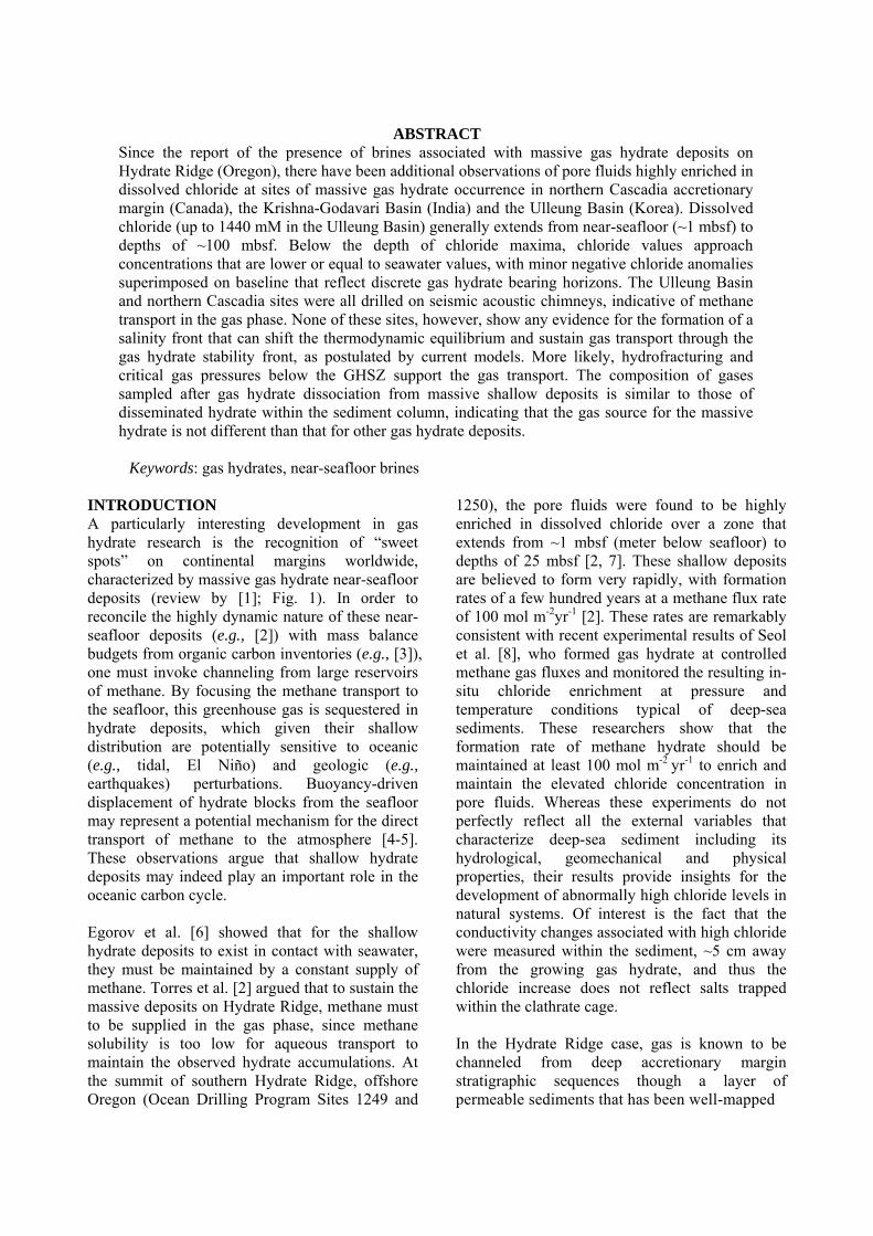
seismically (Horizon A; Fig. 2). This horizon, characterized by coarse-grained sediment, captures and transports substantial quantities of methane gas [9]. Analyses of seismic and core data from Leg 204 suggest that free gas over-pressure may be responsible for hydrofracturing the formation and allowing free gas to migrate towards the ridge summit, where ultimately it is incorporated into gas hydrate, or expelled into the ocean [10]. Alternatively, Milkov et al. [11] and Liu and Flemings [12] suggest that hydrate formation can self-generate a three-phase equilibrium, which permits gas migration through the local gas hydrate stability zone (GHSZ). In their scenario, as solid hydrate forms it generates a high salinity fluid, which shifts the gas hydrate stability field enough to preclude additional gas hydrate formation. This brine supports methane transport as a gas phase, from the base of the GHSZ up to the sediment surface, where it vents. The high-salinity hypothesis is linked to observations of seismic wipe-out zones located beneath a carbonate structure ~250 m away from the summit of Hydrate Ridge, known as “the Pinnacle” ([13]; Fig. 2). This zone has a north-to-south extension of about 150 m and is located within a local topographic depression. The lower slopes are covered with talus blocks several meters in diameter. The Pinnacle is an active fluid pathway, as indicated by bacterial mats and vesicomyid clam communities observed on the carbonate mound [14], and may be channeling the postulated gas-bearing highly saline fluids to the seafloor. There is no observed seismic blanking directly under Sites 1249 and 1250, to indisputably support the presence of upward migration of free gas at these sites. Furthermore, the observed acoustic blanking beneath the Pinnacle at Hydrate Ridge reflects either the presence of a gas-charged zone or the acoustic impedance contrast due to the overlying carbonate structure. It is conceivable that the blanking zone underneath the Pinnacle may be characterized by gas methane transport supported by high salinity fluids, and that the brines observed at Sites 1249 and 1250 reflect lateral migration of the brine in the upper 50 mbsf, as postulated by Milkov et al. [11]. Because the sediments under the Pinnacle were not sampled, the fundamental
Figure 1-A. Summary of global distribution of deep-water fluid vents associated with gas hydrate occurrences (modified from [1]). B. Shallow hydrate occurrence associated with a subsurface brine drilled on the Cascadia margin at Sites 1249 and 1250 (ODP Leg 204) and U1328 (IODP Exp. 311). C. Location of sites drilled offshore India, Site NGHP-01-10 sampled a paleo-seep site with high chloride and high gas hydrate saturation on the Krishna-Godavari (K-G) Basin. D. Location of sites drilled on seismic acoustic chimneys on the Ulleung Basin during Expedition UBGH2. Most of the chimneys do not reach the seafloor, those that breach the seafloor are associated with pockmarks or seafloor mounds.
question of whether the observed gas transport is driven by a saline front that shifts the local GHSZ, or that other processes besides a salinity increase permit methane transport in the gas phase through the GHSZ, remains unanswered. Recent drilling in the Ulleung Basin (offshore Korea) was conducted directly over clearly imaged blanking zones. These chimneys are likely imaging free gas migration pathways [17]; however, they may also arise from energy scattering losses at the seafloor from rough topography, carbonates and perhaps the gas hydrate accumulations themselves, as postulated for northern Cascadia [18]. Here we report on the Ulleung Basin findings, and compare them with published data from additional locations in northern Cascadia and offshore India, where massive shallow gas hydrate deposits co-occur
with the development of a near-seafloor brine. We refer to these occurrences as “brine patches”, rather than using the term “sweet spots” previously utilized, to highlight the characteristic presence of shallow brines. These results reveal that the massive near-seafloor gas hydrates are not supported by the formation of a continuous rising high-salinity fluid column, rather they represent in situ phenomena. GEOLOGIC SETTINGS The Ulleung Basin provides a contrasting scenario to the brine patch on Hydrate Ridge, in that the clear seismic blanking chimneys occur directly underneath the massive gas hydrate deposits, suggesting gas migration towards the seafloor. We draw on data from recent expeditions to the Ulleung Basin and other brine patch localities (Table 1), as described below.
Figure 2-A. Seismic section near the summit of Hydrate Ridge, showing the location of Sites 1249 and 1250 and the carbonate build-up known as the Pinnacle. Dissolved chloride data in the pore fluids; relative borehole resistivity at bit (RAB) as imaged by LWD, and gas hydrate saturation (Sh) estimated from the RAB* for Site 1249 (data from [10]). B. 3.5 kHz subbottom profiler data off Vancouver Island, showing distinct seafloor expression of the acoustic chimney drilled at Site U1328; dissolved chloride data in the pore fluids; relative borehole resistivity at bit (RAB) as imaged by LWD, and gas hydrate saturation (Sh) estimated from the RAB* (data from [15]). *Note: Sh estimates from RAB data in these fracture filled hydrates are known to significantly overestimate the actual saturation values [16], and are shown here only as a relative (semiquantitative) indicator of gas hydrate content.
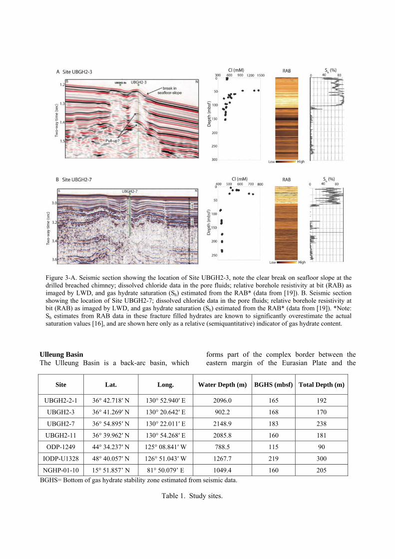
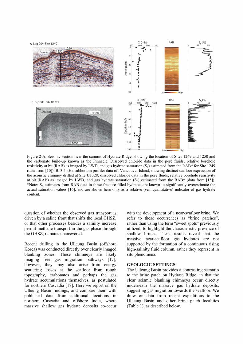
Figure 3-A. Seismic section showing the location of Site UBGH2-3, note the clear break on seafloor slope at the drilled breached chimney; dissolved chloride data in the pore fluids; relative borehole resistivity at bit (RAB) as imaged by LWD, and gas hydrate saturation (Sh) estimated from the RAB* (data from [19]). B. Seismic section showing the location of Site UBGH2-7; dissolved chloride data in the pore fluids; relative borehole resistivity at bit (RAB) as imaged by LWD, and gas hydrate saturation (Sh) estimated from the RAB* (data from [19]). *Note: Sh estimates from RAB data in these fracture filled hydrates are known to significantly overestimate the actual saturation values [16], and are shown here only as a relative (semiquantitative) indicator of gas hydrate content.
Ulleung Basin The Ulleung Basin is a back-arc basin, which
forms part of the complex border between the eastern margin of the Eurasian Plate and the
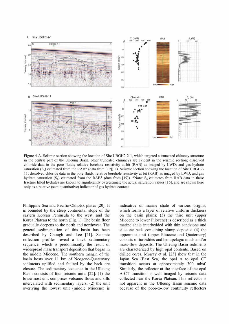
Site Lat. Long. Water Depth (m) BGHS (mbsf) Total Depth (m)
UBGH2-2-1 36° 42.718′ N 130° 52.940′ E 2096.0 165 192
UBGH2-3 36° 41.269′ N 130° 20.642′ E 902.2 168 170
UBGH2-7 36° 54.895′ N 130° 22.011′ E 2148.9 183 238
UBGH2-11 36° 39.962′ N 130° 54.268′ E 2085.8 160 181
ODP-1249 44° 34.237′ N 125° 08.841′ W 788.5 115 90
IODP-U1328 48° 40.057′ N 126° 51.043′ W 1267.7 219 300
NGHP-01-10 15° 51.857’ N 81° 50.079’ E 1049.4 160 205
BGHS= Bottom of gas hydrate stability zone estimated from seismic data.
Table 1. Study sites.
Philippine Sea and Pacific-Okhotsk plates [20]. It is bounded by the steep continental slope of the eastern Korean Peninsula to the west, and the Korea Plateau to the north (Fig. 1). The basin floor gradually deepens to the north and northwest. The general sedimentation of this basin has been described by Chough and Lee [21]. Seismic reflection profiles reveal a thick sedimentary sequence, which is predominantly the result of widespread mass transport deposition that began in the middle Miocene. The southern margin of the basin hosts over 11 km of Neogene-Quaternary sediments uplifted and faulted by the back arc closure. The sedimentary sequence in the Ulleung Basin consists of four seismic units [22]: (1) the lowermost unit comprises volcanic flows and sills intercalated with sedimentary layers; (2) the unit overlying the lowest unit (middle Miocene) is
indicative of marine shale of various origins, which forms a layer of relative uniform thickness on the basin plains; (3) the third unit (upper Miocene to lower Pliocene) is described as a thick marine shale interbedded with thin sandstone and siltstone beds containing slump deposits; (4) the uppermost unit (upper Pliocene and Quaternary) consists of turbidites and hemipelagic muds and/or mass-flow deposits. The Ulleung Basin sediments are characterized by high opal contents. Based on drilled cores, Murray et al. [23] show that in the Japan Sea (East Sea) the opal A to opal CT transition occurs at approximately 300 mbsf. Similarly, the reflector at the interface of the opal A-CT transition is well imaged by seismic data collected near the Korea Plateau. This reflector is not apparent in the Ulleung Basin seismic data because of the poor-to-low continuity reflectors
Figure 4-A. Seismic section showing the location of Site UBGH2-2-1, which targeted a truncated chimney structure in the central part of the Ulleung Basin, other truncated chimneys are evident in the seismic section; dissolved chloride data in the pore fluids; relative borehole resistivity at bit (RAB) as imaged by LWD; and gas hydrate saturation (Sh) estimated from the RAB* (data from [19]). B. Seismic section showing the location of Site UBGH2-11; dissolved chloride data in the pore fluids; relative borehole resistivity at bit (RAB) as imaged by LWD, and gas hydrate saturation (Sh) estimated from the RAB* (data from [19]). *Note: Sh estimates from RAB data in these fracture filled hydrates are known to significantly overestimate the actual saturation values [16], and are shown here only as a relative (semiquantitative) indicator of gas hydrate content.

associated with the preponderance of mass transport deposits that obscure any signal from the postulated diagenetic silica horizon. A large volume of multi-channel seismic reflection data collected from the Ulleung Basin has been used to characterize the gas hydrate and associated free gas distribution in this region [17, 24-28]. Drilling in this basin in 2007 (UBGH1) and 2010 (UBGH2) confirmed the presence of gas hydrate; and the relationships between gas hydrate abundance and lithology have been used by Bahk et al. [29] to classify the gas hydrate occurrences in two different fields: “pore filling”, preferentially associated with discrete sandy horizons and “fracture-filling”, which occurs as veins or nodules within the hemipelagic mud. Seismic acoustic blanking (“chimneys”) are common features in this basin and reach up to 2 km in width [28]. Most of the vertical-seismic wipe-outs terminate within the gas hydrate stability field, but a few extend to pockmarks or mounds on the seafloor [24]. These features may represent vertical gas vents. Four of these seismic-blanking zones were drilled during UBGH2 (Figs. 1, 3, 4). Site UBGH2-3 is located on the southern upper slope of the basin, within a larger vent field. In this location, up to 10 sites of anomalous backscatter intensity reveal a linkage to fracture and/or fault patterns, suggesting that these structural pathways are channeling the
upwardly migrating fluids [30]. Site UBGH2-7 (Fig. 1) was drilled in the northwestern part the basin through a seismic chimney located in a small area of deformation and normal faulting, which is not observed in the sediment surrounding this area. The drilled chimney has a 600 m wide small dome surrounded by a sediment-filled moat, and it intersects a normal fault that may constitute a gas migration pathway. In the central part of the basin, Site UBGH2-11 targeted a chimney associated with a small seafloor disturbance directly underlain by a prominent near-seafloor amplitude anomaly, suggesting possible free gas migration through the GHSZ. The seafloor in this area is punctuated by pockmarks, ~3 m in height. Site UBGH2-2-1 is located ~6 km north of Site UBGH2-11, within the area of pockmark presence. This site, however, targeted a seismic chimney that does not have a surface expression, rather gas migration here is imaged to terminate within the GHSZ. Northern Cascadia Site U1328 was drilled in 2005 during IODP (Integrated Ocean Drilling Program) Expedition 311, on the Cascadia accretionary prism, off the coast of Vancouver Island (Figs. 1 and 2; [15, 31]). It targeted a cold vent with active fluid and gas flow, where gas hydrate occurs near the seafloor; a feature analogous to the massive deposits documented at the summit of Hydrate Ridge [2]. The cold-vent field consists of at least four vents associated with near-surface faults within an area
Figure 5. Seismic section showing the location of Site NGHP-01-10, drilled in the Krishna-Godavari Basin offshore India; dissolved chloride data in the pore fluids; relative borehole resistivity at bit (RAB) as imaged by LWD; and gas hydrate saturation (Sh) estimated from the RAB* (data from [32]). A dramatic increase in sedimentation in the last 3600 kyrs, suggest that sediment loading may have sealed the vent, which is now buried under 16 m of sediment [33]. *Note: Sh estimates from RAB data in these fracture filled hydrates are known to significantly overestimate the actual saturation values [16], and are shown here only as a relative (semiquantitative) indicator of gas hydrate content.
of 2 by 4 km. This field is characterized by near-vertical seismic blank (or wipe-out) zones up to several hundred meters wide, which are aligned along an E-W trend. The most prominent vent in the field, referred to as Bullseye vent, was drilled at Site U1328 and has been the subject of intensive geophysical and geochemical studies since 1999 (e.g., [15, 18]). Krishna-Godavari Basin Seismic data collected from the Krishna-Godavari Basin, located in the middle of the eastern continental margin of India (Fig. 1), reveal the presence of gas hydrates, which was confirmed by drilling in this margin [16, 32, 34]. Of all the sites drilled during the 2006 expedition, Site NGHP-01-10 is relevant to this study as it represents an example of a paleo-seep site that still harbors fracture hosted massive hydrate and a positive chloride fingerprint (Fig. 5). Based on 3D seismic data, Reidel et al. [35] confirmed the association of gas hydrate with fractures and conclude that the gas hydrate at Site NGHP-01-10 is the result of a specific combination of tectonic fault orientations and the abundance of free gas, which migrates from a deeper source. A possible shallow debris flow can be identified along high-resolution 2D seismic lines, which pinch out towards Site NGHP-01-10. A Marion Dufresne core collected in the vicinity of this site, documents the presence of presence of authigenic carbonates and fossil chemosynthetic bivalve shells indicative of a paleo-cold seep, which is now buried by 16 m of sediment [33, 36]. Radiocarbon dating of shells and authigenic carbonates constrain the younger-age limit of the methane expulsion events to ~52 ka ago. METHODS AND RESULTS The Ulleung Basin Gas Hydrate Expedition 2 (UBGH2) was conducted during July-September 2010 to assess the geologic occurrence, regional context, and characteristics of gas hydrates deposits in this basin. Based on extensive seismic surveys [24, 26-27, 37-40], piston coring and prior drilling results [29-30, 38-40], a strategic plan was developed to image thirteen sites using logging while drilling (LWD) techniques, and to core and sample ten sites, in a comprehensive well-integrated program. Here we report on data collected from four sites that targeted seismic blanking zones within the basin [19].
Resistivity-at-bit images (RAB) The electrical resistivity of gas hydrate is higher than that of water-saturated sediments and RAB images depict the electrical resistivity measured at the drill bit as a function of azimuth around the borehole as a hole is drilled. The presence of gas hydrate is apparent in borehole resistivity images, thus providing a continuous record of the subsurface with a spatial resolution in a few centimeters. To estimate the amount of gas hydrate the derived resistivity log data can be used as input to the Archie relation to estimate pore volume water saturations [15, 41]. Gas hydrate saturation (Sh, percentage of pore space in sediment occupied by gas hydrate), is the complement of the water saturation. Gas hydrates in brine patches are likely to be associated with near-vertical faults, and as shown by Lee and Collett [16], gas hydrate saturations using Archie’s equation in fracture dominated settings are likely to result in overestimates, due to the anisotropic nature of reservoirs characterized by gas hydrate occurrence in high-angle fractures. Corrections to these estimates are possible by changing values of Archie parameters; however, these corrections have not been applied to the data presented here. We use these as semi-quantity evidence of larger accumulation of gas hydrate in these brine patches. Even though core recovery in the high resistivity zones drilled during UBGH2 was poor, all the hydrates occur as massive veins and nodules in hemipelagic muds. Visual estimation indicates Sh > 50%, which are consistent with those estimated by logging brine patches in Cascadia (Fig. 2). Pore water analyses Pore water analyses of gas hydrate bearing provinces provide valuable information on the formation and distribution of gas hydrate in marine sediments (e.g., [2, 42-43]). Pore water was extracted from whole round samples collected immediately after retrieval of the core, using standard procedures for sampling, handling and squeezing (e.g., [2, 15]). High-precision chloride concentrations were determined by triplicate titrations using silver nitrate [44]. Chloride measurements are accurate to within 0.4%, and have a standard deviation of 0.2%, based on repeated analyses (n=28) of IAPSO water. Sodium was analyzed by ICP-OES (Prodigy High Dispersion) designed for simultaneous analysis of sample elements and internal standards (1% In and Sc).
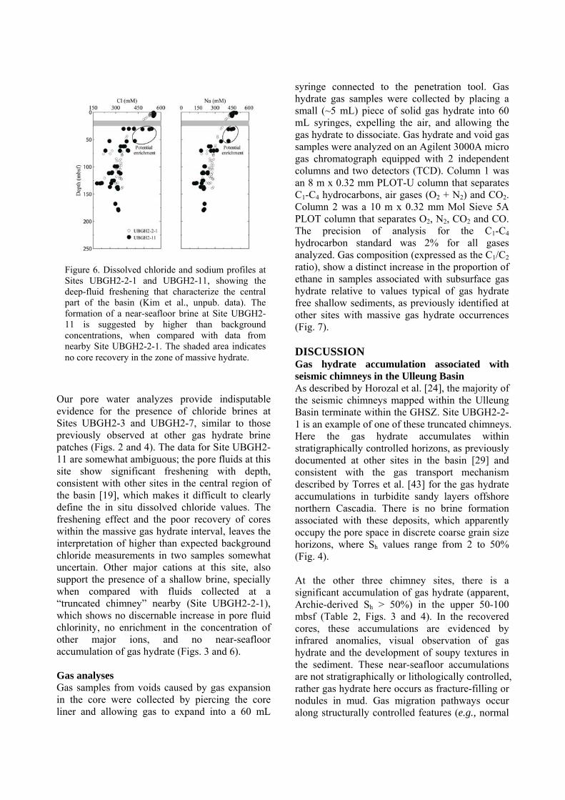
Our pore water analyzes provide indisputable evidence for the presence of chloride brines at Sites UBGH2-3 and UBGH2-7, similar to those previously observed at other gas hydrate brine patches (Figs. 2 and 4). The data for Site UBGH2-11 are somewhat ambiguous; the pore fluids at this site show significant freshening with depth, consistent with other sites in the central region of the basin [19], which makes it difficult to clearly define the in situ dissolved chloride values. The freshening effect and the poor recovery of cores within the massive gas hydrate interval, leaves the interpretation of higher than expected background chloride measurements in two samples somewhat uncertain. Other major cations at this site, also support the presence of a shallow brine, specially when compared with fluids collected at a “truncated chimney” nearby (Site UBGH2-2-1), which shows no discernable increase in pore fluid chlorinity, no enrichment in the concentration of other major ions, and no near-seafloor accumulation of gas hydrate (Figs. 3 and 6). Gas analyses Gas samples from voids caused by gas expansion in the core were collected by piercing the core liner and allowing gas to expand into a 60 mL
syringe connected to the penetration tool. Gas hydrate gas samples were collected by placing a small (~5 mL) piece of solid gas hydrate into 60 mL syringes, expelling the air, and allowing the gas hydrate to dissociate. Gas hydrate and void gas samples were analyzed on an Agilent 3000A micro gas chromatograph equipped with 2 independent columns and two detectors (TCD). Column 1 was an 8 m x 0.32 mm PLOT-U column that separates C1-C4 hydrocarbons, air gases (O2 + N2) and CO2. Column 2 was a 10 m x 0.32 mm Mol Sieve 5A PLOT column that separates O2, N2, CO2 and CO. The precision of analysis for the C1-C4 hydrocarbon standard was 2% for all gases analyzed. Gas composition (expressed as the C1/C2 ratio), show a distinct increase in the proportion of ethane in samples associated with subsurface gas hydrate relative to values typical of gas hydrate free shallow sediments, as previously identified at other sites with massive gas hydrate occurrences (Fig. 7). DISCUSSION Gas hydrate accumulation associated with seismic chimneys in the Ulleung Basin As described by Horozal et al. [24], the majority of the seismic chimneys mapped within the Ulleung Basin terminate within the GHSZ. Site UBGH2-2-1 is an example of one of these truncated chimneys. Here the gas hydrate accumulates within stratigraphically controlled horizons, as previously documented at other sites in the basin [29] and consistent with the gas transport mechanism described by Torres et al. [43] for the gas hydrate accumulations in turbidite sandy layers offshore northern Cascadia. There is no brine formation associated with these deposits, which apparently occupy the pore space in discrete coarse grain size horizons, where Sh values range from 2 to 50% (Fig. 4). At the other three chimney sites, there is a significant accumulation of gas hydrate (apparent, Archie-derived Sh > 50%) in the upper 50-100 mbsf (Table 2, Figs. 3 and 4). In the recovered cores, these accumulations are evidenced by infrared anomalies, visual observation of gas hydrate and the development of soupy textures in the sediment. These near-seafloor accumulations are not stratigraphically or lithologically controlled, rather gas hydrate here occurs as fracture-filling or nodules in mud. Gas migration pathways occur along structurally controlled features (e.g., normal
Figure 6. Dissolved chloride and sodium profiles at Sites UBGH2-2-1 and UBGH2-11, showing the deep-fluid freshening that characterize the central part of the basin (Kim et al., unpub. data). The formation of a near-seafloor brine at Site UBGH2-11 is suggested by higher than background concentrations, when compared with data from nearby Site UBGH2-2-1. The shaded area indicates no core recovery in the zone of massive hydrate.

Figure 7. Methane to ethane (C1/C2) ratios in gas accumulated in voids in non-pressurized cores (circles), from pressure cores (diamonds) and from gas hydrate samples (squares) A. Site UBGH2-3. B. Site UBGH2-7. C. Sites UBGH2-2-1 (open symbols) and UBGH2-11 (closed symbols). D. Site 1249. E. Site U1328. F. Site NGHP-01-10. Vertical bars denote range of C1/C2 ratios typical of near surface gas not affected by gas hydrate; the increase in ethane relative to methane reflects preferential incorporation of C2 into the gas hydrate structure. Data from [11, 15, 19, 32].
fault at Site UBGH2-7), and well-developed vertical fractures are identified in X-radiographs of the recovered material (Fig. 8). There is no evidence for distinct methane plumes, nor for significant chemosynthetic communities (e.g., bacterial mats, bivalves, tubeworms), which characterize sites of active methane seepage [40]. These observations suggest that there is no significant methane discharge to the seafloor at these sites, rather all of the upward flowing methane has been efficiently trapped in the near-seafloor gas hydrate deposits. Site UBHG2-7 intersects a fault, thus suggesting the chimney locations are structurally controlled. There is pervasive faulting of the sediments in this basin, and abundant microfractures have been
documented in RAB and core images [19], so it is likely that some structural control guides the gas migration. Hydrocarbon fractionation during gas hydrate formation and decomposition. Milkov et al. [11] show that variations in the C1/C2 ratio of sediment sections with disseminated gas hydrate show high variability, and reflect enrichment in C2 in the gas hydrate samples relative to the void gases. This enrichment is probably due to molecular fractionation during crystallization [11]. In these samples, where gas hydrate occurs disseminated within the sediment column, the deviations in C1/C2 ratios from the background void values are not very large. On the other hand, Milkov and Xu [45] used hydrocarbon

Site
Depth horizon with massive gas hydrate
(mbsf)
Sh (%)
Cl max
(mM)
Brine patch aread (m2)
CH4 volume (m3 at STP)
Carbon (Tg)
Time needed to form the
deposite (yrs)
References
UBGH2-3 0-100 50b 1438 1.50E+06 8.00E+09 5.7 2379 This study
UBGH2-7 0-80 50b 731 3.00E+05 1.28E+09 0.9 1904 This study
UBGH2-11 10-125 50b 557 This study
ODP-1249 1-30 45a 1008 1.50E+05 1.99E+08 0.1 593 [2,10]
IODP-U1328 5-40 50c 855 4.00E+06 6.89E+09 4.9 769 [15, 18, 31]
NGHP01-10 25-160 26a 634 1.25E+05 4.15E+08 0.3 1483 [16]
a = pressure core data; b = RAB estimates; c= electrical resistivity data; d = seafloor surveys; e = assuming a methane flux of 100 mol m-2 yr-1.
Table 2. Characteristics of brine patches in the Ulleung Basin, Cascadia and Indian margins.
data from Site 1249 to suggest that the near-seafloor gas hydrate at the Hydrate Ridge southern summit is sustained by lateral migration of fluids having a thermogenic signal. It is not clear, then if the distinct composition of the near-seafloor samples reflects a source signal or in situ fractionation. A compilation of hydrocarbon data from various brine patch locations, shown in Figure 7, reveal that all the sites with high gas hydrate saturation in the upper sediment column also display generally low C1/C2 ratios. In the Ulleung Basin and northern Cascadia sites, seismic blanking indicates that each of the brine patches in these locations is sustained by a gas conduit directly underneath the massive hydrate accumulations. No indication of a lateral migration is apparent here. Based on these observations, and the documented preferential incorporation of C2 into the gas hydrate structure [11], we argue that the observed variations in the hydrocarbon composition in samples collected at brine patches on Hydrate Ridge, the Ulleung Basin and elsewhere, reflect dissociation of C2-enriched gas hydrates during recovery of massive gas hydrate bearing cores. There is no difference in the gas composition observed in gas-hydrate bearing horizons from two nearby locations in the central Ulleung Basin: Sites UBGH2-11 (chimney site that reaches the
Figure 8-A. Photograph of Core UBGH2-7D-2H showing massive and nodular gas hydrate. B. X-ray of Core UBGH2-11B-22P showing horizontal accumulation of gas hydrate between 0.6 and 0.8 m of the cored section, and the presence of micro-fractures filled with gas hydrate between 0.3 and 0.1 m of the cored section.

seafloor) and UBGH2-2-1 (truncated chimney), which have similar depletions in C1 relative to C2. These results support the idea that the observed hydrocarbon variations in brine patches result from formation and dissociation of gas hydrate, rather than from a thermogenic-source fingerprint. In the Ulleung Basin there is no apparent difference in the source of hydrocarbons feeding the venting and truncated chimneys. Gas transport-a comparative analysis Since the discovery of massive near-seafloor gas hydrate deposits associated with pore water brines [2, 7], a series of ideas have been put forward to explain the mechanisms responsible for these accumulations. Based on purely thermodynamic considerations, Milkov et al. [11] and Liu and Flemings [12] proposed that gas hydrate formation could generate fluids with a salinity that is high enough to preclude additional gas hydrate formation. As illustrated in Figure 9A, the thermodynamically defined gas hydrate stability curve is highly dependent of the pore fluid salinity. Doubling pore water salinity from 550 to 1100 mM reduces the liquid-gas methane solubility by 15%, and as a result, the base of the GHSZ at Site 1249 shifts from 130 to 90 mbsf [12]. Based on
these equilibrium calculations, Liu and Flemings [12] propose a scenario where formation of gas hydrate at the base of the GHSZ generates enough of a salinity increase to shift the three-phase stability boundary towards the seafloor and allows for free gas migration. As this multiphase system develops, gas migration is sustained by the presence of hyper-saline pore fluids through the GHSZ. The predicted evolution and distribution of gas hydrate and pore fluid salinity are shown in Figure 10A, depicting the development of a salinity front that grows with time from the base of the GHSZ towards the seafloor. More recently, Daigle and Dugan [46] developed another model for gas hydrate formation based on the idea of a salinity-sustained multiphase flow within the GHSZ. They incorporate in their model, the nucleation of fractures when the excess pore pressure exceeds the vertical hydrostatic effective stress, eventually allowing gas to vent to the seafloor. Their results suggest a scenario where a salinity increase is called upon to sustain the three-phase equilibrium within the GHSZ, but both salinity and Sh show a marked increase at about 38 mbsf where fractures initiate.
Figure 9-A. Thermodynamic estimates gas hydrate stability (three-phase equilibrium) for chloride concentrations typical of seawater (550 mM) and for a chloride brine (1100 mM); the geothermal gradient and depth of the gas hydrate stability zone (GHSZ) for Site 1249 at Hydrate Ridge is shown. It illustrates the predicted shallowing of the GHSZ as salinity increases, which forms the basis for a postulated salinity front to support methane gas transport through the GHSZ (from [12]). B. Pressure and stress estimated, showing that at the Hydrate Ridge summit the gas pressure at the gas-charged layer (Pg) approximately equals the lithostatic stress (L), and Pg is hypothesized to parallel L though the GHSZ. Pw = hydrostatic pressure (modified from [10]).

A comparison of these results with the field observations from the Ulleung Basin and elsewhere, indicate that whereas Daigle and Dugan’s [46] model better reproduces the near-seafloor discontinuity in the dissolved chloride and Sh distributions, it also predicts the presence of very high salinity throughout the GHSZ. In spite of these model results, none of the brine patches drilled to date show any indication of a salinity front, and more significantly, in the center of the Ulleung Basin we observe a massive gas hydrate deposit in a region where diagenetic processes at depth have significantly freshened the pore fluids (Figs. 4 and 10; [19]). Neither Site UBGH2-11, in which the seismic chimney is observed to reach the seafloor, nor the truncated chimney drilled at Site UBGH2-2-1 (a potential incipient vent), show any salinity front growing from the base of the GHSZ to the seafloor. The low background chlorinity values observed at these sites, place them further away from a three-phase equilibrium, and further indicate that these systems are likely to be controlled by geomechanical and structural factors rather than by thermodynamic equilibrium constraints. At Hydrate Ridge, Tréhu et al. [10] demonstrated that when enough free gas accumulates below the GHSZ, it can generate enough pressure to induce hydrofracturing in the overlying sediment (Fig. 10). If the volume fraction of gas is > 10%, interconnection of gas-filled pores transmits hydrostatic pressures from greater depths because of the low density of the gas phase. As shown by Fleming et al. [47] and Tréhu et al. [10], the excess (non-hydrostatic) pressure at the top of the gas layer may be sufficient to fracture the sediments and drive gas towards the seafloor. The lack of any evidence for the development of the salinity-front predicted by the thermodynamic models (Fig. 10) indicates that vertical migration of free gas to the seafloor is likely to be sustained by critical gas pressures below the base of the GHSZ that generate random pathways of upwardly moving gas stringers [10, 47-48]. This is supported by the logging while drilling (LWD) and wireline logs collected from Site U1328 that show steeply dipping resistivity anomalies at several depths, typical of fractures filled with gas hydrate or possibly free gas. These potential gas migration conduits, seen as blanked zones on the seismic data from this area, may be connected to the
Figure 10-A. Postulated evolution of a chloride and hydrate saturation fronts, due to sustained gas flow from below. T1 to T3 illustrate three stages of development, from a deep-front at T1 to a steady state profile when the brine-sustained gas column reaches the seafloor (modified [12]). B. Results of a similar salinity-sustained model by Daigle and Dugan [46], which incorporates the effect of hydrofracturing at approximately 38 mbsf. C. Data from various sites of massive seafloor hydrate showing that background chloride concentration below the near-surface brine either approaches seawater values (e.g., Sites 1249, UBGH2-3, and UBGH2-7) of indeed may even show effect of fluid freshening at depth (e.g., Site UBGH2-11). The truncated chimney drilled at Site UBGH2-2-1, which may represent the initial stages in the development of a vent site, also has fresh fluids at depth.

seafloor chemosynthetic cold vent communities observed by bottom video surveys, and support massive gas hydrate accumulation in the upper few tenths of meter of sediment [15, 18, 31]. Structural pathways for gas transport are also commonly observed within the Ulleung Basin seismic volume; indeed Site UBGH2-7 targeted a chimney that is clearly associated with a normal fault. Faults are also observed in the vicinity of Sites UBGH2-3 and UBGH2-11, and small fractures have been observed in RAB images and in visual and X-ray imaging of the cores (Fig. 8). Formation and evolution of brine patches As a first order approximation of the amount of carbon trapped in these brine patch deposits, we use Sh estimates based on various proxies, an average porosity of 50%, the depth interval of massive hydrate occurrence and an extrapolation to the areal distribution of the brine patch, as shown in Table 2. These estimates, which may be off by a factor of two, indicate that each of the brine patches in the Ulleung Basin host from 0.5 to 5 Tg carbon. If we further assume, based on the number of gas chimneys that breach the seafloor in this basin, that there are about 30 such sites, then near surface gas hydrate deposits may sequester ~125 Tg carbon. The Ulleung Basin sites are comparable to deposits hosted by brine patches elsewhere. If, for the sake of argument, we assume that there are 200 to 500 such localities around the
world, the amount of carbon would be in the order of 25 to 62.5 x 10³ Tg carbon (or 25 to 62.5 Gigatons). This is estimated to be 0.25 to 12% of the total amount of carbon trapped in gas hydrate globally, which ranges from 500 to 10,000 Gigatons [49]. Although a relative small reservoir, this type of concentrated shallow deposit is more susceptible to perturbations in bottom water temperature and pressure, may be impacted by global warming and may provide a mechanism for efficiently transferring methane from the seafloor to the atmosphere [4]. Based on a one-dimensional model of the chlorinity increase in the near-surface sediments of Hydrate Ridge, Torres et al. [2] estimated that these deposits would form in a time frame of 500 to 1500 years. Using a simple box model calculation, and estimate of methane fluxes in Hydrate Ridge of 100 mol m-2yr-1, the time needed to form these deposits was estimated to be ~1000 years [2]. Similarly, the laboratory experiments of Seol et al. [8], suggest that a minimum flux of 100 mol m-2yr-1 is needed to sustain the chloride anomalies. If we use this value as the minimum methane flux feeding the brine patches, we can estimate the time needed to form the Ulleung Basin deposits to be ~1000 to 3000 years. For comparison, Ussler and Paull [42] show that the disseminated gas hydrate deposits in the Blake Ridge are at least 40,000 years old, since it takes
Figure 11. Schematic diagram showing various stages in the development of a brine patch. Site UBGH2-2-1 is likely to represent the initial stages in the development of a vent site. Here gas moves through the sediment column through coarse sediment layers, where both gas and gas hydrate accumulate [43]. When the gas column reaches a depth horizon where hydrofracturing may be sustained (e.g., [2, 46]) gas hydrate will form in near-seafloor brine patches. After sustained venting, seafloor expressions of methane discharge (chemosynthetic communities and authigenic carbonates) develop, as observed at Site U1328. Site NGHP-01-10 represents a paleo-seep, where an active brine patch got buried by a mass sediment transport that sealed the vent.
approximately that amount of time to dissipate the high chloride pulse generated during gas hydrate formation. Thus brine patches may represent a type of marine gas hydrate deposit with “renewal rates” that are much shorter than those for gas hydrate accumulations in coarse sands. Brine patches suggest the following stages for such sites (Fig. 11). Site UBGH2-2-1 may be considered an end-member location, where the gas transport ends within the GHSZ. Gas hydrate accumulations here are associated with coarse sedimentary layers [19, 29] and there is no brine development. The geochemical characteristics of the gas and pore fluids at this site, are similar to that of a nearby chimney that breaches the seafloor (Site UBGH2-11). This and other brine patches at chimney sites in the Ulleung Basin represent more mature systems where a sustained methane flux feeds the formation of the near-seafloor hydrate deposits (Fig. 11B). In the Ulleung Basin, however, there are no observations of significant gas plumes in the water column, nor are there surface manifestations of methane discharge in the form of chemosynthetic communities such as those observed at other methane seep sites (e.g., Sites 1249 and U1328). Discrete authigenic carbonate blocks were found at Sites UBGH2-7 and UBGH2-11, but these are not as extensive in size and coverage as those present in the Cascadia margin seeps. One possibility is that the locations with massive carbonate pavements (such as those drilled in the Cascadia margin) represent an older manifestation of the system, which has been venting methane to the seafloor for extended periods; carbonates on Hydrate Ridge yield an age of 0.8 to 6.4 ka, and “older” seeps in the margin yield ages of up to 260 ka [50]. An alternative explanation is that high accumulation of opal in Ulleung Basin, and subsequent diagenetically induced dewatering has resulted in overpressures and hydrofracturing, so that as one path is cemented with gas hydrate the gas discharge will migrate to a nearby site, resulting in the observed abundance of fractures and seismic chimneys in different stages of development. This second scenario implies that the Ulleung Basin is in effect efficiently trapping all the upwardly migrating methane within the near-seafloor gas hydrate deposits, and will explain the thicker zones of massive hydrate accumulation (up to 100 m) compared to those in the Cascadia margin (up to 50 m). A third scenario would call for these
chimneys to have formed in the recent geologic past, but that the methane supply has since been shut off, thus no active supply of methane is currently available to sustain living chemosynthetic communities. Therefore, it is not yet clear if the Ulleung Basin chimneys represent a young stage in the evolution of these brine patches, or if they are in a senescent stage. Future studies involving dating of carbonates, pore water modeling and detailed seafloor surveys will aid in establishing the nature and history of the formation of brine patches in the Ulleung Basin. The Indian margin Site NGHP-01-10 is included in this summary, as it represents an example of a well-documented paleo-seep site. Methane expulsion, as recorded in authigenic carbonates and bivalve shells, is likely to have begun here ~58 ka ago [36]. Significant gas hydrate accumulations formed during a period that lasted until ~3.6 ka [33], when the methane vents were likely sealed via rapid sediment burial, as indicated by slump deposits imaged in seismic data. Since then the chloride anomaly has been decreasing due to diffusion, and efforts to model this processes are underway. CONCLUSIONS Massive gas hydrate and chloride brines in near-seafloor sediments along continental margins are not at all uncommon, and may represent a significant carbon reservoir, which is susceptible to oceanographic perturbations. Whereas the location of the Hydrate Ridge brine may be interpreted as a flow of gas-charged salty fluids under the Pinnacle, the northern Cascadia and Ulleung Basin sites penetrated structures with well-defined acoustic blanking. Results from drilling at these sites clearly demonstrate that there is no self-sustaining gas flow triggered by the development of a high salinity fluid that inhibits gas hydrate formation at depth. Results obtained by drilling brine patches to date are more consistent with the idea that critical gas accumulations can generate enough pressure to force gas migration through the GHSZ. The composition of gases sampled after gas hydrate dissociation from massive shallow deposits is similar to those of disseminated hydrate within the sediment column, indicating that the gas source for the massive hydrate is not different than

that for gas hydrate deposits in coarse sand layers not associated with pore fluid brines. Preliminary estimates suggest that there is approximately 125 x 10-3 Gt of carbon trapped in the Ulleung Basin brine patches. If we assume that there are 200-500 such locations sites worldwide, this will represent a ~25 to 62.5 Gt carbon, which is 0.25 to 12% of the total carbon thought to be sequestered in gas hydrate deposits globally. REFERENCES [1] Mazurenko LL, Soloviev VA. Worldwide
distribution of deep-water fluid venting and potential occurrences of gas hydrate accumulations. Geo-Marine Letters 2003; 23(3-4):162-176.
[2] Torres ME, Wallmann K, Tréhu AM, Bohrmann G, Borowski WS, Tomaru H. Gas hydrate growth, methane transport, and chloride enrichment at the southern summit of Hydrate Ridge, Cascadia margin off Oregon. Earth Planetary Science Letters 2004;226(1-2):225-241.
[3] Hensen C, Wallmann K. Methane formation at Costa Rica continental margin -Constraints for gas hydrate inventories and cross-décollement fluid flow. Earth and Planetary Science Letters 2005;236(1-2):41-60.
[4] Brewer PG, Paull CK, Peltzer ET, Ussler W III, Rehder G, Friederich GE. Measurements of the fate of gas hydrates during transit through the ocean water column. Geophysical Research Letters 2002;29(22):2081, doi:10. 1029/2002GL014727.
[5] Paull CK, Brewer PG, Ussler W III, Peltzer ET, Clague D, Rehder G. An experiment demonstrating that marine slumping is a mechanism to transfer methane from seafloor gas-hydrate deposits into the upper ocean and atmosphere. Geo-Marine Letters 2003;22(4): 198-203
[6] Egorov AV, Crane K, Vogt PR, Rozhkov AN. Gas hydrate that outcrop on the seafloor: stability models. Geo-Marine Letters 1999;19 (1-2):68-75.
[7] Haeckel M, Suess E, Wallmann K, Rickert D., Rising methane gas bubbles form massive hydrate layers at the seafloor Source. Geochimica et Cosmochimica Acta 2004;68 (21):4335-4345.
[8] Seol J, Koh D-Y, Cha M, Shin W, Lee Y-J, Kim J-H, Lee J, Lee H. Experimental verification of anomalous chloride enrichment related to methane hydrae formation in deep-sea sediments. AIChE Journal 2011;doi:10. 1002/aic.12555 (in press).
[9] Tréhu AM, Bohrmann G, Rack F, Torres ME, et al. drilling Gas Hydrates on Hydrate Ridge, Cascadia Continental Margin. Proceedings of the Ocean Drilling Program Initial Reports Leg 204; College Station, TX: Ocean Drilling Program, 2003. [Online] http:// www-odp.tamu.edu/publications/204_IR/204ir.htm
[10] Tréhu AM, Flemings PB, Bangs NL, Chevalier J, Gracia E, Johnson J, Liu C-S, Liu X, Riedel M, Torres ME. Feeding methane vents and gas hydrate deposits at south Hydrate Ridge. Geophysical Research Letters 2004;31;L23310, doi:10.1029/2004GL021289.
[11] Milkov AV, Claypool GE, Lee Y-J, Torres ME, Borowski WS, Tomaru H, Sassen R, Long P, the ODP Leg 204 Scientific Party. Ethane enrichment, propane depletion, and other compositional variations in subsurface gases: A new indicator of gas hydrate occurrence in marine sediments. Organic Geochemistry 2004;35(9):1067-1080.
[12] Liu X, Flemings PB. Passing gas through the hydrate stability zone at southern Hydrate Ridge, offshore Oregon. Earth and Planetary Science Letters 2006;241(1-2):211-226.
[13] Torres ME, Bohrmann G, Brown K, deAngelis M, Hammond D, Klinkhammer G, McManus J, Suess E, Tréhu AM. Geochemical observations on Hydrate Ridge, Cascadia margin, Data Report. 174, ref. 99-3; Corvallis, OR: OSU College of Oceanic and Atmospheric Sciences, 1999.
[14] Linke P, Suess E. RV Sonne Cruise Report SO148 Tecflux-II-2000, ISSN 0936-5788. Kiel, Germany: GEOMAR, 2001.
[15] Riedel M, Collett TS, Malone MJ, the Expedition 311 Scientists. Cascadia Margin Gas Hydrates, Proceedings of the Integrated Ocean Drilling Program Volume 311; Washington DC: Integrated Ocean Drilling Program Management International Inc., 2006. doi:10.2204/iodp.proc.311.2006 [Online] http: //iodp.tamu.edu/publications/exp311/311title.htm.
[16] Lee MW, Collett TS. Gas hydrate saturations estimated from fractured reservoir at Site NGHP-01-10, Krishna-Godavari Basin, India

Source. Journal of Geophysical Research B: Solid Earth 2009;114:B07102, doi:10.1029/ 2008JB006237.
[17] Haacke RR, Hyndman RD, Park K-P, Yoo D-G, Stoian I, Schmidt U. Migration and venting of deep gases into the ocean through hydrate-chocked chimneys offshore Korea. Geology 2009;37(6):531-534, doi:10.1130/G25681A.1.
[18] Riedel M, Spence GD, Chapman NR, Hyndman RD. Seismic investigations of a vent field associated with gas hydrates, offshore Vancouver Island. Journal of Geophysical Research B: Solid Earth 2002;107(B9):2200, doi:10.1029/2001JB000269.
[19] UBGH2 Scientists. Ulleung Basin Gas Hydrate Drilling Expedition 2. Preliminary Report. Daejeon, Republic of Korea; KIGAM, 2010.
[20] Tamaki K, Honza E. Incipient subduction and obduction along the Eastern margin of the Japan Sea. Tectonophysiscs 1985;119(1-4): 381-406.
[21] Chough S-K, Lee K-E. Multi-stage volcanism in the Ulleung back-arc basin, East Sea (Sea of Japan). Island Arc 1992;1(1):32-39.
[22] Chough SK, Choi DK, Kwon S-T, Ree J-H. Tectonic and sedimentary evolution of the Korean peninsula: A review and new view. Earth Science Reviews 2000;52(1-3):175-235.
[23] Murray RW, Brumsack HJ, von Breymann MT, Sturz AA, Dunbar RB, Gieskes JM. Diagenetic reactions in deeply buried sediments of the Japan Sea: A synthesis of interstitial-water chemistry results from Legs 127 and 128. In: Pisciotto KA, Ingle JC, Von Breymann MT, editors. Proceedings of the Ocean Drilling Program Scientific Results Volume 127/128; College Station, TX: Ocean Drilling Program, 1992. p. 1261-1274.
[24] Horozal S, Lee GH, Yi BY, Yoo DG, Park KP, Lee HY, Kim WS, Kim HJ, Lee K. Seismic indicators of gas hydrate and associated gas in the Ulleung Basin, East Sea (Japan Sea) and implications of heat flows derived from depths of the bottom-simulating reflector. Marine Geology 2009;258(1-4):126-138
[25] Lee JH, Baek YS, Ryu BJ, Riedel M, Hyndman RD. A seismic survey to detect natural gas hydrate in the east Sea of Korea. Marine Geophysical Researches 2005;26(1): 51-59.
[26] Yoo DG, Kang DH, Koo NH, Kim WS, Kim GY, Kim BY, Chung SH, Kim YJ, Lee HY, Park KP, Lee GH, Park SC. Geophysical evidence for the occurrence of gas hydrate in the Ulleung Basin, East Sea. Journal of Geological Society of Korea 2008;44(5):645-655 (in Korean with English abstract).
[27] Kang DH, Yoo DG, Bahk JJ, Ryu BJ, Koo NH, Kim WS, Park KS, Park KP, Kim JS. The occurrence patterns of gas hydrate in the Ulleung Basin, East Sea. Journal of Geological Society of Korea 2009;45(2): 143-155 (in Korean with English abstract).
[28] Ryu B-J, Riedel M, Kim J-H, Hyndman RD, Lee Y-J, Chung B-H, Kim I-S. Gas hydrates in the western deep-water Ulleung Basin, East Sea of Korea. Marine and Petroleum Geology 2009;26(8):1483-1498.
[29] Bahk J-J, Um I-K, Holland M. Core lithologies and their constraints on gas hydrate occurrence in the East Sea, offshore Korea; Results from site UBGH1-9. Marine and Petroleum Geology 2011;in press.
[30] Bahk J-J, Kim J-H, Kong G-S, Park Y, Lee H, Park Y, Park KP. Occurrence of near-seafloor gas hydrates and associated cold vents in the Ulleung Basin, East Sea. Geosciences Journal 2009;13(4):371-385.
[31] Riedel M, Hyndman RD, Novosel I, Spence GD, Chapman RN, Solem RC, Lewis T. Geophysical and geochemical signatures associated with gas hydrate-related venting in the northern Cascadia margin. Bulletin of the Geological Society of America 2006;118(1-2):23-38.
[32] Collett TS, Riedel M, Cochran JR, Boswell R, Preley J, Kumar P, Sethl A, Lall M, Sibal V. National Gas Hydrate Program (NGHP) Expedition 01 Initial Reports, New Delhi, India: Ministry of Petroleum and Natural Gas, Directorate General of Hydrocarbons, 2008.
[33] Connoly EC, Johnson J, Torres ME, Teichert BMA, Giosan L, Rose K. New Insights from sediment ages and carbon nisotopes at a paleo-seep chemoshynthetic biological community in the Krishna-Godavari basin, offshore India. AGU Fall Meeting, San Francisco, CA,2009.
[34] Shankar U, Riedel M, Sathe AV. Geothermal modeling of the gas hydrate stability zone along the Krishna Godavari Basin Source. Marine Geophysical Researches 2010;31(1-2):17-28.
[35] Riedel M, Collett TS, Kimar P, Sathe AV,Cook A. Seismic imaging of a fractured gas hydrate system in the Krishna Godavari Basin offshore India. Marine and Petroleum Geology 2010;31(7):17-28.
[36] Mazumdar A, Dewangan P, Joao HM, Peketi A, Khosla VR, Kocherla M, Badesab FK, Joshi RK, Roxanne P, Ramamurty PB, Karisiddaiah SM. Evidence of paleo–cold seep activity from the Bay of Bengal, offshore India. Geochemistry Geophysics Geosystems 2009; 10(6):Q06005, doi:10.1029/2008GC002337.
[37] KIGAM. Studies on geophysical exploration of gas hydrate, NP2007-020-2007(1). Gwacheon, Republic of Korea: Ministry of Knowledge Economy, 2007.
[38] KIGAM. Analysis of gas hydrate deep-drill cores and studies on gas hydrate stability and geohazards, NP2007-021-2007(1). Gwacheon, Republic of Korea: Ministry of Knowledge Economy, 2007.
[39] KIGAM. Analysis of gas hydrate deep-drill cores and studies on gas hydrate stability and geohazards, NP2008-003-2008(1). Gwacheon, Republic of Korea: Ministry of Knowledge Economy, 2008.
[40] KIGAM. Studies on gas hydrate geology, geochemistry, and stability, NP2008-003-2009(2) Gwacheon, Republic of Korea: Ministry of Knowledge Economy, 2009.
[41] Collett TS, Ladd J. Detection of gas hydrate with downhole logas and assessment of gas hydrate concnetrations (saturations) and gas volumes on the Blake Ridge with electirical resisitivity log data. In: Paull CK, Matsumoto R, Wallace PJ, Dillion WP, editors. Proceedings of the Ocean Drilling Program Scientific Results 164. College Station TX: Ocean Drilling Program, 2000. p. 179-191.
[42] Ussler W, Paull CK. Ion Exclusion Associated with Marine Gas Hydrate Deposits. In: Paull CK, Dillon WP, editors. Natural Gas Hydrates: Occurrence, Distribution, and Detection. Geophysical Monograph Series 124, Washington D.C.: American Geophysical Union , 2001. p. 41-51.
[43] Torres ME, Tréhu AM, Cespedes N, Kastner M, Wortmann UG, Kim J-H, Long P, Malinverno A, Pohlman J, Riedel M, Collett T. Methane hydrate formation in turbidite sediments of northern Cascadia, IODP Expedition 311. Earth Planetary Science Letters 2008;271(1-4):170-180.
[44] Gieskes J, Gamo T, Brumsack H-J. Chemical methods for interstitial water analysis aboard JOIDES Resolution. Ocean Drilling Program Technical Note 15. College Station TX: Ocean Drilling Program, 1991
[45] Milkov
AV, Xu W. Comment on “Gas hydrate growth, methane transport, and chloride enrichment at the southern summit of Hydrate Ridge, Cascadia margin off Oregon” by Torres et al [Earth Planet. Sci. Lett. 226 (2004) 225-241]. Earth and Planetary Science Letters 2005;239(1-2):162-167.
[46] Daigle H, Dugan B. Effects of multiphase methane supply on hydrate accumulation and fracture generation Source. Geophysical Research Letters 2010;37:L20301, doi;10. 1029/2010GL044970.
[47] Flemings PB, Liu X, Winters W. Critical pressure and multiphase fluid flow in Blake Ridge gas hydrates. Geology 2003;31(12) 1057-1060.
[48] Impey MD, Grindrod P, Takase H, Worgan KJ. A capillary network model for gas migration in low-permeability media. SIAM Journal on Applied Mathmatics 1997; 57(3):597-608.
[49] Milkov AV. Global estimates of hydrate-bound gas in marine sediments: How much is really out there? Earth-Science Reviews 2004; 66(3-4):183-197.
[50] Teichert BMA, Eisenhauer A, Bohrmann G, Haase-Schramm A, Bock B, Linke P. U/Th systematics and ages of authigenic carbonates from Hydrate Ridge, Cascadia Margin: Recorders of fluid flow variations. Geochimica et Cosmochimica Acta 2003;67(20):3845- 3857.
ACKNOWLEDGEMENTS The data used for this research were collected from the 2nd Ulleung Basin Gas Hydrate Drilling Expedition (UBGH2) in 2010, which was supported and funded by consortium organizations of the Korean Gas Hydrate Development Program, such as Ministry of Knowledge Economy (MKE), Gas Hydrate R&D Organization (GHDO), Korea Institute of Geoscience and Mineral Resources (KIGAM), Korea National Oil Corporation (KNOC) and Korea Gas Corporation (KOGAS). We sincerely thank the scientists and technical staff working for the UBGH2 from GHDO, KIGAM, KNOC, KOGAS, the U.S. Geological Survey (USGS), and the Geological Survey of

Canada (GSC). We also deeply appreciate the crew of the D/V Fugro Synergy, and staff of Geotek for their excellent support for the UBGH2. We specially want to acknowledge K. Clauson, M. Bertolli, M. Marius and R. Atsma for their invaluable assistance in the chemistry laboratory. Support to M. E. Torres and M. Kastner for the field participation and analyses of data from the Indian and Cascadia margins was provided by the National Energy and Technology Laboratory of the US Department of Energy (NETL-DOE), and the US Science Support Program (USSSP) for the Integrated Ocean Drilling Program.