obstacle awareness and collision avoidance radar …
TRANSCRIPT
OBSTACLE AWARENESS AND COLLISION AVOIDANCE RADAR SENSOR SYSTEM FOR
LOW-ALTITUDE FLYING SMART UAV
Young K. Kwag and Jung W Kang, Avionics Dept. AERC, Hankuk Aviation University, Seoul, Korea
Presentation by Genya Fridlyand
OBJECTIVE
Obstacle awareness and collision avoidance is consideredthe most important issue in the field of unmanned vehicles.
While this technology is in use for manned vehicles, it is stillin the development and test phase for unmanned vehicles.in the development and test phase for unmanned vehicles.
Objective: propose a suitable radar sensor system for unmanned aircrafts
2
UNMANNED AERIAL VEHICLES
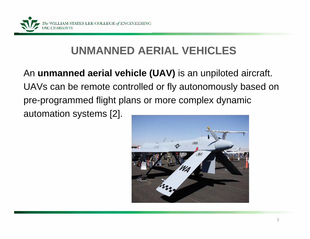
An unmanned aerial vehicle (UAV) is an unpiloted aircraft.UAVs can be remote controlled or fly autonomously based on pre-programmed flight plans or more complex dynamic automation systems [2].
3
PROBLEMS WITH UAVS
In the past seven years, the UAV average mishap ratehas been 4.28; compared to the Air Force mishap rateaverage during that same time of 1.12, UAV mishaps are very high [3].
4
• limited camera angles
• extremely poor pilot-to-airplane interface
• reaction time
• boredom
AVAILABLE TECHNOLOGIES
Current cooperative systems in use for manned aerialvehicles include:
5
• Traffic Alert Collision Avoidance System (TCAS)• Automatic Dependent Surveillance-Broadcast (ADS-B)
Traffic Alert Collision Avoidance System (TCAS)
TCAS involves communication between all aircraft equipped with an appropriate transponder [4].
Each TCAS-equipped aircraft "interrogates" all other aircraftin a determined range about their position and all other craftreply to other interrogations [4].
This interrogation-and-response cycle may occur severaltimes per second [4].
6
Traffic Alert Collision Avoidance System (TCAS)
TCAS I - first generation of collision avoidance technology;Alerts pilot of traffic; no suggestion of remedy [4].
TCAS II - used in commercial aircrafts. Offers all benefits of TCAS I. Offers the pilot direct, vocalized instructions to avoidDanger [4].
TCAS III - "next gen" of collision avoidance technology. Currently suspended; no further plans for development [4].
7
Non-Cooperative Systems
Non-cooperative systems use sensors to measure theavoidance information of the obstacles using active orpassive methods
Active sensors emits energy to obstacles and receives the Active sensors emits energy to obstacles and receives the reflecting energy. Passive sensors only receive energyradiated from obstacles.
• Electro-optical sensors• Electromagnetic radar sensors
8
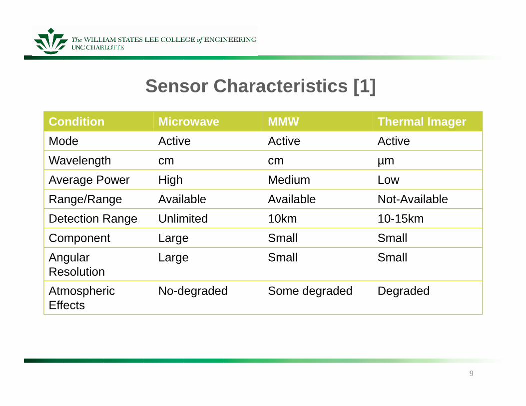
Sensor Characteristics [1]
Condition Microwave MMW Thermal Imager
Mode Active Active Active
Wavelength cm cm µm
Average Power High Medium Low
Range/Range Available Available Not-Available
9
Range/Range Available Available Not-Available
Detection Range Unlimited 10km 10-15km
Component Large Small Small
Angular Resolution
Large Small Small
AtmosphericEffects
No-degraded Some degraded Degraded
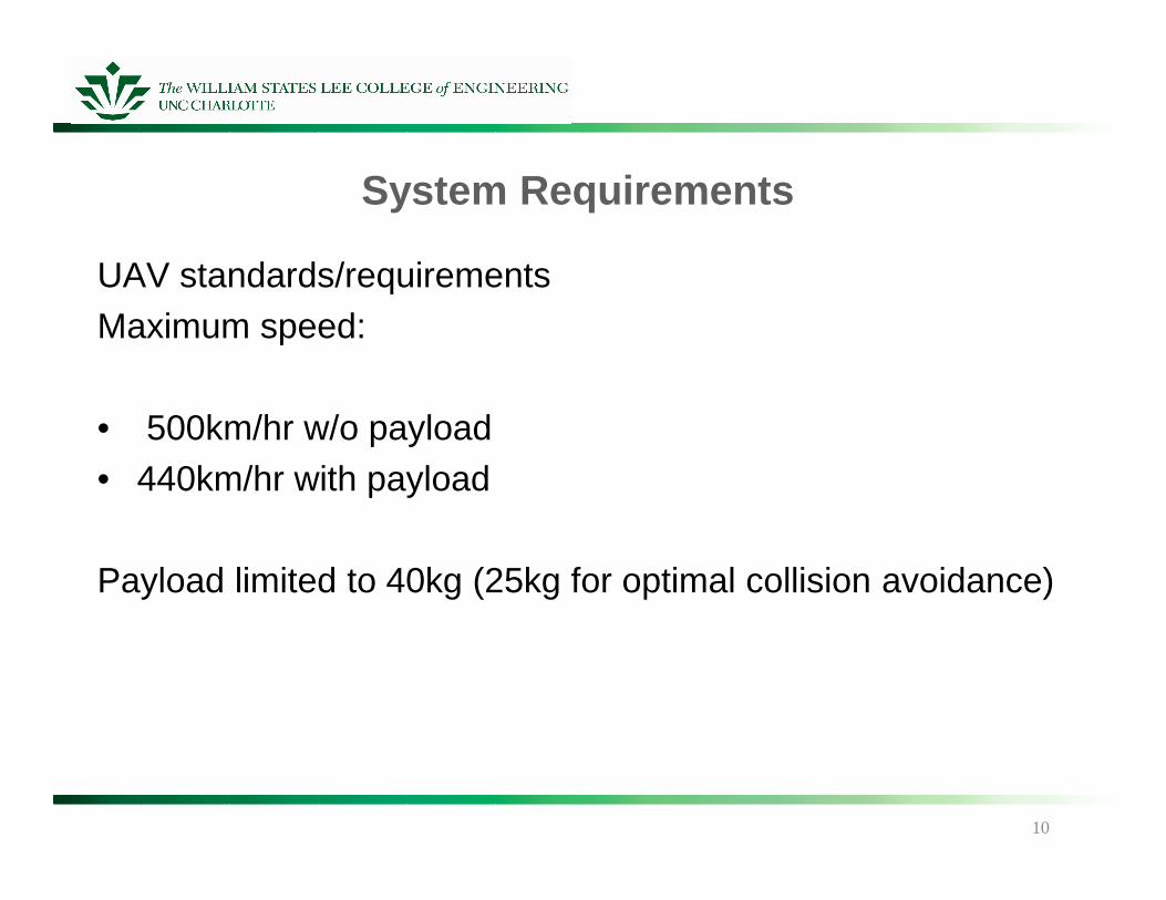
System Requirements
UAV standards/requirementsMaximum speed:
• 500km/hr w/o payload• 440km/hr with payload
Payload limited to 40kg (25kg for optimal collision avoidance)
10
Sensor Requirements Consideration
• Real-time measurement capability (most important)• Operational environment• Payload constraints • Payload constraints • Air safety regulation (ELOS)
11
Real-Time Measurement Capability
• Range/range rate• Bearing in azimuth• Elevation
12
Operation Environment
• Day and night operational capability• Vehicle maneuverability• Endurance time in air• Rain, wind, hail, lightning, etc.• Electronic counter-countermeasures (ECCM) capability
13
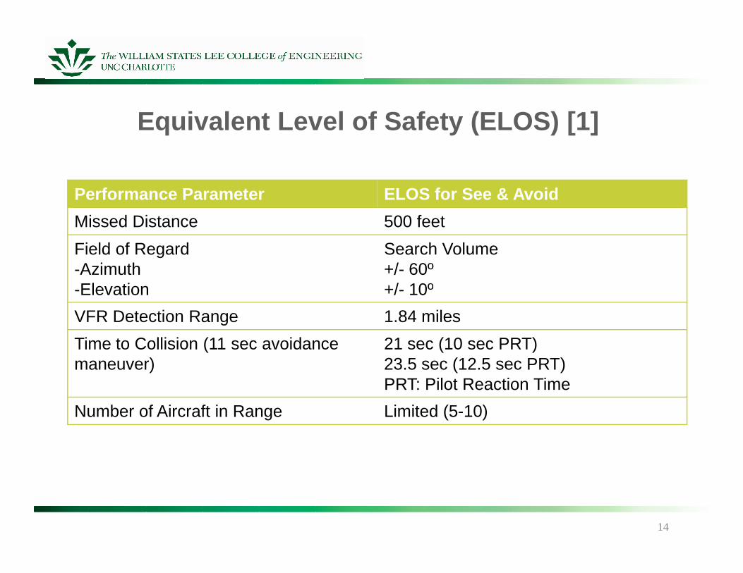
Equivalent Level of Safety (ELOS) [1]
Performance Parameter ELOS for See & Avoid
Missed Distance 500 feet
Field of Regard-Azimuth-Elevation
Search Volume+/- 60º+/- 10º-Elevation +/- 10º
VFR Detection Range 1.84 miles
Time to Collision (11 sec avoidance maneuver)
21 sec (10 sec PRT)23.5 sec (12.5 sec PRT)PRT: Pilot Reaction Time
Number of Aircraft in Range Limited (5-10)
14
Most Promising Method
Non-cooperative active radar sensor used as primarycollision avoidance sensor. Specifically the millimeter waveradar (MMW).
However, cooperative methods such as TCAS and/or ADS-Bcould be considered an alternative option for the back-upsystem.
15
Obstacle Awareness and Collision Avoidance System (OACAS) Concept
Consists of CAS radar sensor and OCAS processor.
The CAS radar constitutes the antenna, transmitter/receiver,signal processor, and data processor.
The OCAS processor can be contained in the radar dataprocessor or be part of the Digital Flight Control Computer(DFCC).
16
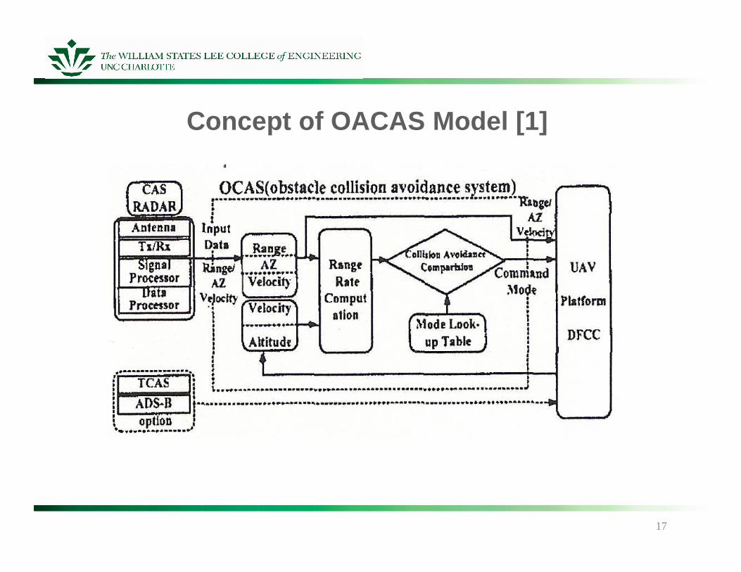
Concept of OACAS Model [1]
17
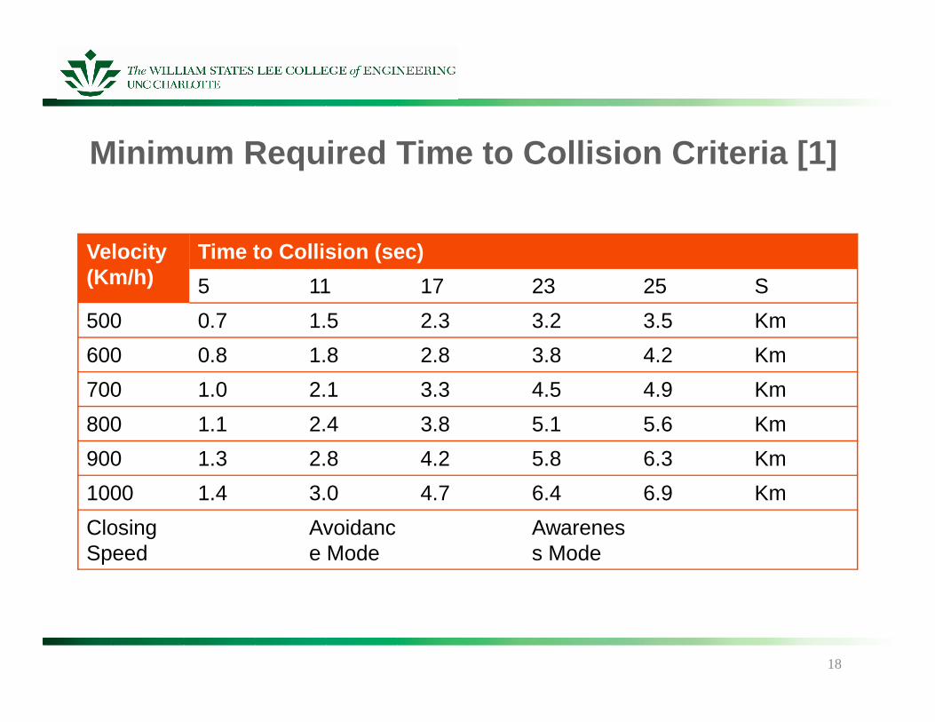
Minimum Required Time to Collision Criteria [1]
Velocity (Km/h)
Time to Collision (sec)
5 11 17 23 25 S
500 0.7 1.5 2.3 3.2 3.5 Km
600 0.8 1.8 2.8 3.8 4.2 Km600 0.8 1.8 2.8 3.8 4.2 Km
700 1.0 2.1 3.3 4.5 4.9 Km
800 1.1 2.4 3.8 5.1 5.6 Km
900 1.3 2.8 4.2 5.8 6.3 Km
1000 1.4 3.0 4.7 6.4 6.9 Km
ClosingSpeed
Avoidance Mode
Awareness Mode
18
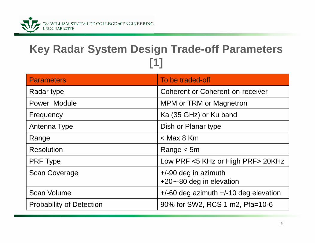
Key Radar System Design Trade-off Parameters [1]
Parameters To be traded-off
Radar type Coherent or Coherent-on-receiver
Power Module MPM or TRM or Magnetron
Frequency Ka (35 GHz) or Ku band
Antenna Type Dish or Planar type
Range < Max 8 Km
Resolution Range < 5m
PRF Type Low PRF <5 KHz or High PRF> 20KHz
Scan Coverage +/-90 deg in azimuth+20~-80 deg in elevation
Scan Volume +/-60 deg azimuth +/-10 deg elevation
Probability of Detection 90% for SW2, RCS 1 m2, Pfa=10-6
19
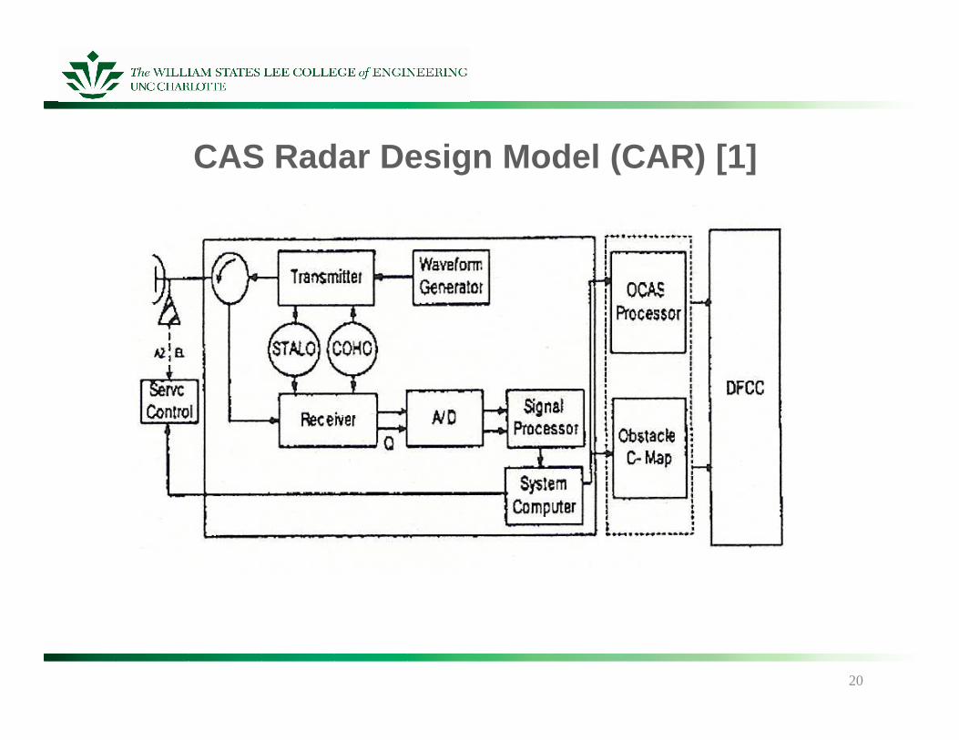
CAS Radar Design Model (CAR) [1]
20
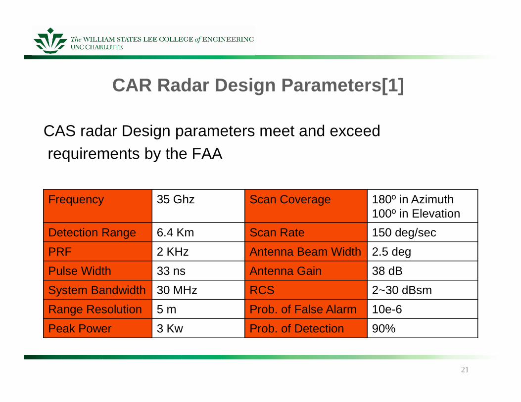
CAR Radar Design Parameters[1]
Frequency 35 Ghz Scan Coverage 180º in Azimuth
CAS radar Design parameters meet and exceedrequirements by the FAA
Frequency 35 Ghz Scan Coverage 180º in Azimuth100º in Elevation
Detection Range 6.4 Km Scan Rate 150 deg/sec
PRF 2 KHz Antenna Beam Width 2.5 deg
Pulse Width 33 ns Antenna Gain 38 dB
System Bandwidth 30 MHz RCS 2~30 dBsm
Range Resolution 5 m Prob. of False Alarm 10e-6
Peak Power 3 Kw Prob. of Detection 90%
21
Obstacle Detection Problems
There is slight discrepancy with the shape and actual size ofstationary and moving objects detected by the radar.Problems can arise when extremely high accuracy is needed.
22
Conclusion
After comparing both the cooperative and non-cooperativemethods it was determined the non-cooperative methods arecurrently the most feasible. How ever the OASAS conceptpresented is a promising possibility of future avionics.presented is a promising possibility of future avionics.
QUESTIONS?
23
Cited Sources
[1] Young K and Jung W Kang, “Obstacle Awareness and Collision Avoidance Radar Sensor System For Low-Altitude Flying Smart UAV” Korean Airspace Research Institute. Downloaded Jan 14, 2009
[2] Wikipedia, “Unmanned Arial Vehicle” http://en.wikipedia.org/wiki/Unmanned_aerial_vehicle. Accessed on Jan 23, 2009. Last updated Jan 22, 2009.Jan 23, 2009. Last updated Jan 22, 2009.
[3] Abizer Tyabji, “Unique problems associated with UAV employment” BNET Business Network; Flying Safety. Accessed on Jan 23, 2009 http://findarticles.com/p/articles/mi_m0IBT/is_5_63/ai_n19396165Last Updated May, 2007.
[4] Wikipedia, “Traffic Collision Avoidance System”, http://en.wikipedia.org/wiki/TCAS#TCAS_I Accessed on Jan 24, 2009. Last Updated Jan 23, 2009.
24