observations on pile design and construction practices in...
TRANSCRIPT

ORIGINAL PAPER
Observations on Pile Design and Construction Practices in India
Shailesh R. Gandhi1
Received: 3 November 2015 / Accepted: 5 November 2015 / Published online: 17 November 2015
� Indian Geotechnical Society 2015
Abstract This paper reviews the design and construction
practices on pile foundation being adopted in India
observed over the last three decades. The factors that affect
the choice of the pile have been discussed highlighting the
necessity of initial field tests prior to the detailed design. A
case study is presented where choice of the pile was made
based on initial field tests on piles of promising types. The
common problems faced during pile construction in each
type of pile with possible remedial measures that can
improve the performance are described. Various issues in
pile design are reviewed with some of the experimental and
numerical work carried out on lateral load on piles in slope,
pile group effect under lateral load, negative drag force,
rock-socketed pile, etc. Finally, the need for more such
full-scale field tests and monitoring with instrumentation is
emphasized to achieve an optimum pile design along with
few case studies on such tests carried out. The review
reveals remarkable improvements, both in the design and
construction, comparable with that in other countries.
Keywords Pile design � Pile construction � Field tests �Group effect � Negative drag � Case study
Introduction
In early 80’s, bored cast-in situ piles and driven cast-in situ
piles were widely used. The technology for precast piling
was picking up. Very few projects used precast piles with a
limited size as the spliced pile technology was not in use.
However, pile use was extensive due to lack of confidence
in various ground improvement methods. The choice of
pile type was based on availability of piling equipments. It
was very rare that initial pile test on two or more promising
pile type are carried out to arrive at the choice and corre-
sponding pile capacity. The phenomenon of the effect of
pile driving, negative drag force on pile, methods of
reducing drag force, reduction in lateral capacity due to
pile group effect was not known precisely. The concept of
instrumented field test to verify the design parameters was
picking up though with a difficulty in procuring the
instrument at high cost. Considerable improvements have
been visualized in the last three decades which has
improved the confidence level in pile design as well as
construction. Effective interaction between the client,
geotechnical designer and the contractor is desirable to
constantly review the field test results (preferably with
suitable instrumentation) and accordingly modify the
design. Many of the design parameters can be evaluated
better based on field testing as they are highly dependent on
the specific strata, equipment used and the method of
construction.
During early 80’s most of the designs followed the
codes of practices which are based on past experience
using conservative parameters. In several instances the
field test results have shown much higher load capacity
compared to the theoretically estimated capacity. However,
in very few cases the design is modified as the field test
results are generally available only after sizable work has
& Shailesh R. Gandhi
1 Department of Civil Engineering, Indian Institute of
Technology Madras, Chennai 600036, India
123
Indian Geotech J (January–March 2016) 46(1):1–15
DOI 10.1007/s40098-015-0171-5

been completed. Instrumented field tests which can provide
vital information on actual capacity with individual share
from different layers were particularly very rare due to the
high cost of imported instruments. Also the clients gener-
ally have a notion that an instrumented test is more an
academic exercise and does not benefit the project.
Bored cast-in situ piles and driven cast-in situ piles were
the most commonly adopted as precast pile technology was
limited. Only very few projects used precast driven piles,
some used imported spun pipe piles and even large diam-
eter pre-stressed pipe pile cast at site. Precast piles are still
not available off the shelf in the market and a casting yard
is essential in each site which sometimes do not permit use
of this type due to lack of space or due to less number of
piles justifying the setting up of a casting yard. The driven
cast-in situ piles have limited diameter of about 550 mm
and depth of 25–30 m below the ground level whereas in
case of bored piles, large diameters of 1.5–1.8 m have been
used. The technology available permits the bored pile
construction to large depth exceeding 60 m, socketing the
pile in any rock for several meters and installing it even
through water in challenging marine environment.
As far as construction technology is concerned, most of
the bored piles, even for major projects were installed by a
conventional tripod with a chisel and a bailer or with direct
mud circulation (DMC) method. The use of rotary piling
rigs was available much later during 80’s. The conventional
method using a tripod is very slow and less effective in use
of temporary liner to a deeper level, lowering of steel cage
in parts with number of lap joints, concreting with a tremie
pipe, etc. The rotary rig on the other hand, is much faster in
installing a temporary liner to a large depth and for pile
construction. However, one of the major problem in use of
rotary rigs is lack of continuous circulation of the bentonite
slurry (unlike in the case of a DMC method) which may
result in gradual increase in the slurry density as well as
viscosity if not checked and replaced. The increase in slurry
density can result in suction pressure under the operating
bucket resulting in reduced capacity of pile and difficulties
in concreting, if not taken care adequately.
Pile design methods are well established but the selec-
tion of key parameters such as earth pressure coefficient K,
adhesion factor a, etc. has been a real challenge. If a
project schedule does not permit adequate initial field
testing to evaluate some of the important parameters, the
design is made with a conservative approach. A detailed
analysis using p–y, t–z and q–z curves is rarely done for the
land piles. The interactions effect among the piles under
vertical load is taken care by providing 2.5D or 3D spacing
if piles are terminated on rock or in soil respectively.
However reduction due to the interaction effect under the
horizontal loads has to be evaluated as this can be signif-
icant even if a spacing of 3D is provided.
The codes on pile design do not give adequate infor-
mation on evaluation of the negative drag force on piles
passing through settling soil layers, methods to reduce the
drag force, etc. Different approach is observed in assessing
the safe capacity when subjected to drag force. It may be
noted that this parameter cannot be obtained based on load
test as the settling layers will offer positive friction during
the period of testing. Some of the above aspects have been
discussed in detail in the following section based on either
case study or detailed analysis carried out.
Choice of Pile Type
Ideally, choice of pile type is dependent on several factors
such as strata conditions, availability of equipments,
method followed for construction, loading requirements,
etc. The most crucial parameter governing the pile per-
formance is method of construction which is found to have
large variations.
In case of bored pile (non-displacement pile) in cohesion
less soil or in stiff clay, constant presence of bentonite
slurry along the wall of the bore hole as well as formation
of filter cake can reduce the frictional resistance. On the
other hand, a driven pile (displacement pile) will densify
the surrounding strata in the process of installation. Driving
of the pile will normally result in densification of the sur-
rounding soil and increase in the normal stress on pile
surface resulting in higher frictional resistance. Similar
increase is expected in the end bearing resistance also. In
view of the above, the driven piles are known to have better
performance compared to bored pile of similar size, except
in sensitive clay stratum where driven pile can have
reduced capacity. Other factors favoring use of precast
driven piles are high grade of concrete with good quality
control, neat site condition as no bentonite slurry is used,
possibility of applying a slip layer to reduce the drag load,
assessment of pile capacity during driving based on ‘‘set’’
value, higher lateral capacity, easy to install with a rake,
faster construction, etc.
In sensitive cohesive soil, driving of a pile creates re-
molding of clay strata in the surrounding. Depending on the
sensitivity of the strata there is corresponding reduction in
the shear strength and hence reduction in capacity of the
pile. In such case, bored piles (non displacement method)
prove better.
When pile socketing is required in hard strata, either to
carry higher compression load or for uplift load, driven pile
cannot penetrate deep into such strata. For soft rocks such
as chalk, mud stone, shale, etc. it is possible to drive the
pile into such rock and derive higher capacity. For other
variety of weather rock or hard strata, driving will result in
high driving stress and possible damage to pile, and
2 Indian Geotech J (January–March 2016) 46(1):1–15
123
breaking of rock mass into smaller fragments surrounding
the pile tip resulting in reduced capacity. On the other
hand, boring through a hard stratum with a chisel will
result in a very rough socket to which the in situ concrete
gets strongly bonded resulting in higher friction. Whenever
socketing in hard strata is required, bored cast-in situ pile is
more appropriate. Some of the other factors favoring bored
piles are less percentage of steel, less head room require-
ments, less noise and vibrations, etc.
Above factors do not help the design engineers in choice
of pile type as the soil strata may comprises of several
layers with varying properties. Initial field test on
promising pile type therefore helps to get the following
information:
• Choice of pile type (based on the actual performance at
site).
• Establish that the proposed equipments/method can be
used for installation of the required pile size to the
required depth.
• To confirm the capacity and to optimize the pile design
under vertical compression, pull out and lateral loads.
• Difficulty faced, if any during execution so that
suitable remedial measures in the installation procedure
can be included in the tender specifications.
• Structural designer can prepare the pile layout with
more confidence and revisions in pile layout due to
revision in capacity can be minimized.
From execution point of view, conducting such initial
tests prior to award of piling contract is difficult unless a
separate tender is made exclusively for installing the test
piles and for conducting the initial load tests. This will
obviously have higher cost due to mobilization of the
equipments for a limited number of piles. However, in
view of the above benefits, the higher cost of a separate
tender for few initial test piles can always be justified in the
case of a major project. There are several instances where
the initial tests are carried out only after the piling work has
been awarded and the test results demand changes in either
pile size or pile capacity resulting in revisions in drawings
which implies several contractual issues and can delay the
work.
Case Study on Pile Choice
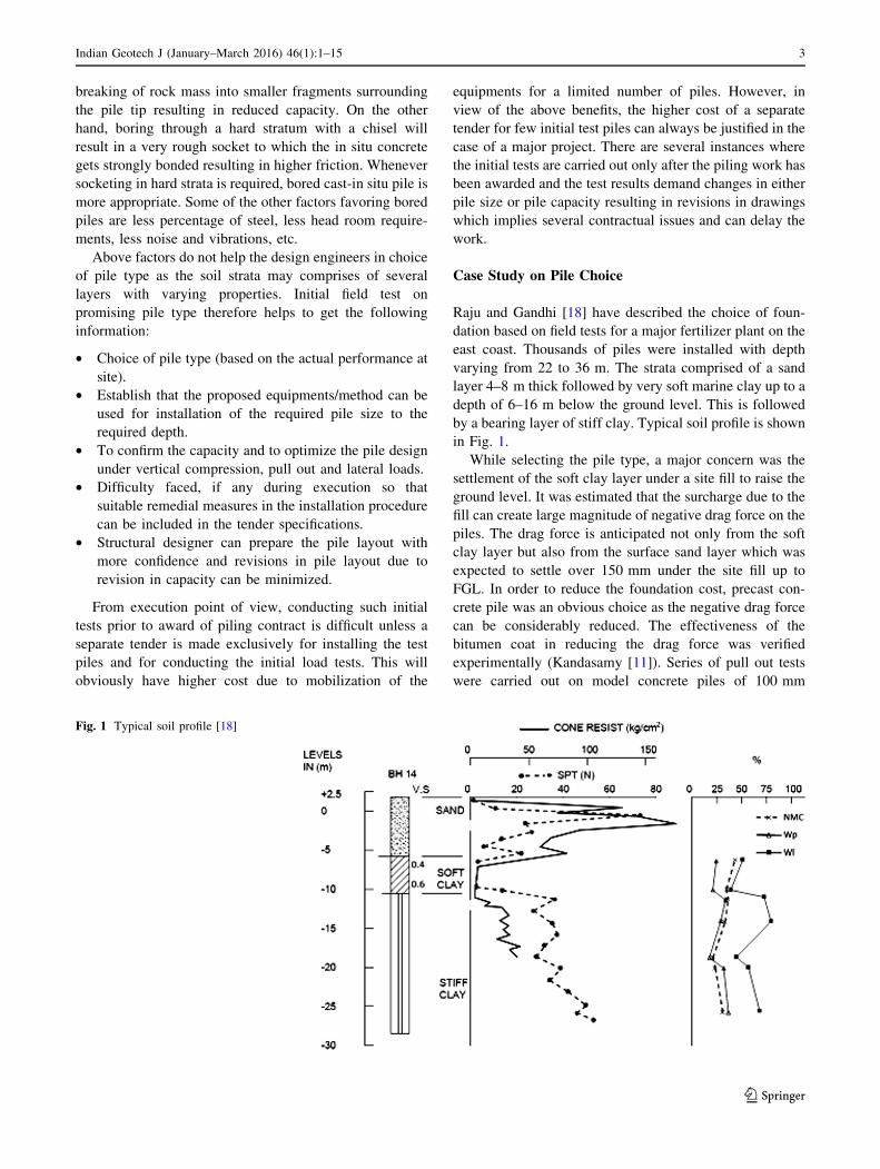
Raju and Gandhi [18] have described the choice of foun-
dation based on field tests for a major fertilizer plant on the
east coast. Thousands of piles were installed with depth
varying from 22 to 36 m. The strata comprised of a sand
layer 4–8 m thick followed by very soft marine clay up to a
depth of 6–16 m below the ground level. This is followed
by a bearing layer of stiff clay. Typical soil profile is shown
in Fig. 1.
While selecting the pile type, a major concern was the
settlement of the soft clay layer under a site fill to raise the
ground level. It was estimated that the surcharge due to the
fill can create large magnitude of negative drag force on the
piles. The drag force is anticipated not only from the soft
clay layer but also from the surface sand layer which was
expected to settle over 150 mm under the site fill up to
FGL. In order to reduce the foundation cost, precast con-
crete pile was an obvious choice as the negative drag force
can be considerably reduced. The effectiveness of the
bitumen coat in reducing the drag force was verified
experimentally (Kandasamy [11]). Series of pull out tests
were carried out on model concrete piles of 100 mm
Fig. 1 Typical soil profile [18]
Indian Geotech J (January–March 2016) 46(1):1–15 3
123

diameter and 600 mm long, with and without bitumen coat.
Typical load displacement behavior under pull out load is
shown in Fig. 2. According to this study, the drag force
could be reduced by 60–90 %. Though precast concrete
piles can be economical by reducing the drag force sig-
nificantly, there were uncertainties about the availability of
contractors for installing driven piles to such large depth.
Also it was necessary to verify the performance of this pile
type in the field due to the lack of experience in precast pile
construction.
To decide on pile type, two promising pile types,
namely precast driven piles and bored cast-in situ piles
were selected for the initial tests. Three pairs of a precast
pile and a bored pile of comparable dimensions were
installed and load tested. The precast piles had a square
cross section of 400 mm 9 400 mm whereas bored cast-
in situ pile had a diameter of 450 mm. The length of all 6
piles was about 22 m with nearly 6 m penetration in the
bearing stiff clay layer. During testing, the friction contri-
bution of the top sand layer which is likely to add a neg-
ative drag force was eliminated by providing an oversize
casing around the pile up to the bottom of the sand layer
and removing the sand in the annular gap between the pile
and the casing. Each of these piles was loaded till failure
using conventional kentledge method. The load test results
are shown in Fig. 3. As can be seen, the precast driven piles
have consistently better performance compared to the
bored piles. All the three driven piles have higher ultimate
resistance and much smaller displacement. Based on these
field test results, finally precast driven piles were adopted
for the project. Following criteria was adopted while
selecting the pile length and capacity.
• Structures with significant horizontal load, piles were
used with 6 m penetration in the stiff clay with a design
capacity of 900 kN as indicated by the test results.
Though the structural capacity is not fully utilized, the
number of piles required will be more to meet the
lateral loads.
• Structures where the vertical load was governing the
number of piles, pile length was increased up to 34 m
with about 12–14 m penetration in stiff clay to achieve
a higher capacity of 1100–1300 kN.
As the friction contribution from the top sand layer was
anyway not to be considered due to the bitumen coat
application, water jetting technique was used for the initial
penetration of the piles up to the bottom of sand layer.
Special water nozzles were attached to a pipe about 12 m
long on the two diametrical opposite faces and water was
jetted under pressure of about 1000 kPa. With jetting
action, the pile was sinking in the ground very fast under its
self weight itself. Once a penetration of 10–12 m was
achieved, the water pipes were withdrawn and the pile was
driven with drop hammer up to the founding level. This
made the pile installation very fast and also reduced the
noise/vibration level in the surrounding area.
During execution, 22 additional routine load tests were
carried out to confirm the above capacity which showed
satisfactory results. Each pile, after deducting the reduced
negative drag could support a design load of about
800–1300 kN compared to 500–600 kN only estimated in
the case of bored pile.
Difficulties in Pile Installation
While there has been considerable improvements in the
piling equipments and know-how in pile construction, there
are several possibilities of defects in the pile installation.Fig. 2 Effect of bitumen coating on pull out resistance [18]
Fig. 3 Comparison of precast and bored piles [18]
4 Indian Geotech J (January–March 2016) 46(1):1–15
123

Based on the past experience, some of the common prob-
lems noticed in pile installation procedure are highlighted
below. These problems are less where the piling contractor
is experienced and has well trained staff to execute the
works. The piling contractors may hire locally available
technicians who may not have adequately experience for
this specialized job. It is also noticed often that the piling
equipments are locally fabricated and do not have some of
the essential features which can significantly affect the
piles installed.
Precast Driven Piles
The main difficulty is in handling a larger size of pile in
terms of cross section as well as length. Unless the number
of piles to be installed is large and adequate space is
available to establish a casting yard, this type cannot be
adopted. Many times, the choice of this pile type is not
considered due to above limitations. Another difficulty is in
prediction of pile length which may vary if the strata have
variations resulting in excess length projecting out which
needs to be cut little above the cut-off level, if the hard
stratum is found to be at higher level. On the other hand, if
the hard stratum is at deeper level, it needs to be further
driven with a follower section made of steel and later
grown with in situ concrete. Segmental piles are being used
which can address the above issues but the cost of the joint
(some have been patented) is high.
The capacity of pile can be estimated during driving
based on set value and a detailed pile drivability anal-
ysis. The set value is dependent on number of parame-
ters such as weight of the pile cap, stiffness of the
cushion, soil damping parameters, etc. which are not
reflected in Hiley’s formula. Narasimha Rao and Gandhi
[16] carried out a detailed parametric study using the
wave equation to find the influence of the above
parameters on the resulting set value and driving stresses
which can help to choose an optimum weight of the pile
cushion for an efficient driving.
Many times, where stratum is cohesion less, water
jetting technique can be used instead of driving with a
hammer. While this reduces the time of installation,
noise and vibration problems, it does loosen the sur-
rounding strata and reduces the frictional resistance as
well as end bearing resistance and the lateral capacity.
The loosening of strata created by water jetting can be
partly rectified if last few meters of the pile is driven
with a hammer.
If above limitations are taken care of, this type has
several advantages and provides better performance. Pre-
cast piles, including hollow pipe piles of large dimensions
have been successfully used in the country in spite of above
difficulties.
Driven Cast-In Situ Piles
Driven cast-in situ piles also have limitations on size. The
maximum diameter for which the equipments are available
is limited to 500–600 mm and the depth to which installed,
even with a jointed casing pipe is limited to 30–35 m. The
water tightness of the joint between the pile shoe and the
casing is very important as the pile is driven several meters
below the ground water level and any accumulation of
seepage water through this joint will affect the quality of
concrete at pile tip. Many times accumulated water is
found at the bottom which needs to be checked and cleared
before concreting. Another problem faced is about uplifting
of the casing pipe due to buoyancy before the steel cage is
lowered. If pile tip is resting on hard strata, such upward
movement can reduce the effective end bearing capacity.
Concreting of pile and withdrawing of the casing also need
an experienced operator to maintain a minimum height of
fresh concrete within the casing while withdrawing to
ensure that the outside ground water/soil do not force into
the casing. Stage wise pouring of concrete and adequately
tapping the casing with driving hammer at the top is
essential to ensure that the concrete is compacted and
occupies the gap created by the thickness of the casing pipe
and the projected portion of the pile shoe. Driving of a pile
adjacent to a freshly installed pile can be avoided as this
may affect the concrete which has not adequate strength to
withstand the displacement/vibrations. Unless adequate
spacing exist between the piles, it is better to install
alternate piles.
Bored Cast-In Situ Piles
It is often seen that small piles of diameter 400 mm or
under-reamed pile of diameter 300 mm is being used.
These will have severe constraint of flow of concrete
through a small size tremie pipe which shall be of mini-
mum 200 mm internal diameter.
Soil collapse during the boring operation is a common
problem, in spite of bore hole stabilization with bentonite
slurry, particularly in a loose cohesion less saturated soil.
The temporary liner used has generally a limited depth of
2–5 m below the ground level as the withdrawal of the
casing pipe with conventional tripod rig is difficult. For a
good quality concrete, it is preferable to use a liner to its
full length and withdraw the same after concreting. This is
possible with rotary rigs which have a special attachment
for installing the casing. Such casing pipes are with joints
and can be installed or withdrawn by applying the static
force plus torque by the machine. This will ensure good
quality of pile and ensure no extra consumption of con-
crete. In many situations, sacrificial permanent steel liners
have been used to a large depth which is very expensive. In
Indian Geotech J (January–March 2016) 46(1):1–15 5
123

case of rock socket, it shall be ensured that the liner, if used
do not penetrate in the rock socket but it is terminated just
below the rock surface. This is to ensure that there is no
gap between the rock cut surface and the casing in which
the concrete cannot flow and the skin friction from rock can
be affected. In the absence of a liner, concrete gets strongly
keyed to the rough rock surface and provide better fric-
tional resistance.
Even if a liner is used, it is important to stabilize the
bore with proper bentonite slurry with proper density and
other properties throughout the pile construction. Proper-
ties of the bentonite used, ratio of water to bentonite
adopted, density, pH values, etc. are to be regularly
checked and the slurry shall be replaced if it does not meet
the requirements.
Piling by rotary rigs and chisel/bailer method do not
have a continuous circulation of the bentonite. Many times
it is noticed that the bentonite slurry level in the bore hole
is not maintained up to the top of the bore hole and it keeps
going down every time the bucket is withdrawn. This can
result in serious inward seepage of ground water into the
bore hole and loosening of the soil strata around the pile
shaft. Use of polymer slurry instead of bentonite slurry is
being used increasingly though the cost is high due to
several merits.
Suction pressure created while withdrawing the operat-
ing tool from the bore hole is often a problem which can
result in serious damage to the soil strata prior to com-
pletion of the pile. In rotary rigs particularly, where con-
tinuous bentonite circulation is not provided and the
machine is powerful to withdraw the tool at high speed,
there are more chances of suction effect. The operating tool
shall have adequate provision of vertical openings within
the tool which permit free flow of the bentonite slurry
through the tool while it is withdrawn.
Cleaning the bottom of the bore hole before concreting
also has limitations, particularly in DMC method where the
upward flow velocity of the slurry is not always adequate to
carry the cut soil particles, unless there is no large gravel
size particles or stones. Inadequate cleaning of the bottom
results in soft toe and reduces the pile capacity. The
problem is more when depth of the pile is large and in such
case use of air lift system to flush out the sediments is
essential.
Marine pile construction in locations with high tidal
variations above 5 m in certain area such as Kandala,
Hazira, Dahej, etc. requires special precautions. During
boring operation through the steel liner, when the tide level
is lowest, the level of slurry or sea water in the casing may
remain up to the top and can create a piping failure due to
high seepage flow under the tip of the casing if the pene-
tration beyond the seabed bottom is not adequate.
Similarly, inward flow can also occur when the tide level is
high and the slurry level in the casing pipe is not main-
tained above the tide level. Both the above situations can
result in considerable loosening of the strata around the pile
and reduction in frictional capacity. This can be eliminated
by increasing the liner penetration adequately to limit the
exit gradient to a safe limit.
Concreting with a tremie pipe requires several checks
such as minimum diameter of the pipe, ensuring that
bentonite slurry in the borehole do not get mixed with the
fresh concrete, maintaining minimum penetration of the
pipe in the fresh concrete while withdrawing the tremie
pipe, pouring extra concrete above the cut-off level to
ensure that the contaminated concrete at the interface
between the concrete and the slurry is eliminated, etc.
Unless the rig operator is experienced, ensuring the above
is difficult and often leads to a defective pile.
While preparing the pile head, there are different
methods used to eliminate the contaminated concrete above
the cut-off level. The usual practice is to chip-off the
concrete manually with chisel and hammer to a reasonable
finish at the cut-off level. This has to be done after the
concrete gains the required strength to ensure that the
concrete below the cut-off do not get damages during the
chipping-off operation. Sometimes very heavy hammer is
used to remove this extra concrete and that can damage the
pile concrete below the cut-off. Use of a hydraulic system
which has number of radial jacks can also be used which
can crush the concrete little above the cut-off without
impact under the static jack force is better and faster.
Another practice is to remove the contaminated portion
above the cut-off level immediately after casting of the
pile. The removal can be either manual if the cut-off is
closer to the ground level or using a special tool which
permits scoop out the contaminated concrete from dipper
level. Adequate care shall be taken to ensure that concrete
is not removed below the cut-off level.
Precast Pre Bored Pile
This type is used very rarely though it derives the benefits
of both precast and bored pile. Casting of these piles
requires a grout pipe to be centrally placed which can make
the needle compaction difficult particularly for smaller
section. Also, if the length of the pile is more, and splice
joint needs to be adopted, making a splice joint after
lowering one piece which is still suspended in bore hole
and providing the grout pipe through the joint is difficult.
The method is not suitable where a rock/hard stratum is not
available to terminate the pile. This is because the frictional
resistance is reduced due to the presence of grout around
the pile surface.
6 Indian Geotech J (January–March 2016) 46(1):1–15
123

Pile Design Issues
Vertical Compression Load
As far as design of pile foundation is concerned, the for-
mulae to arrive at the vertical compression load carrying
capacity based on the known soil parameters are well
established in the code [10]. These recommendations are
generally in line with the other codes. However, certain key
parameters which govern the capacity are often debat-
able as discussed below:
• Restricting the effective vertical stress for estimating
the skin friction also to 15–20 times the pile diameter,
as in the case of estimating the end bearing resistance.
The necessity of restricting this is not well understood
and it is often observed that if restricted, the pile length
predicted is very high and driving becomes difficult or
the load test shows a very conservative design.
• The co-efficient of earth pressure K, which is recom-
mended to be 1–2 for a bored pile and 1–3 for a driven
pile, is highly dependent on the method of installation.
In case of large projects, this shall be evaluated by back
calculating from the field test results preferably on
instrumented test pile for an optimum design. However,
some of the consultants do recommend a very conser-
vative value and do not even permit to use the value
based on load test results.
• In the case of rock socketed pile, [9] recommends not to
consider any frictional resistance from the overburden
soil. This is reasonable as the tip resting in rock may
not have any significant settlement and mobilization of
shear in overburden layers with limited relative move-
ment between the pile and soil cannot be justified.
Therefore it is preferable to derive the entire resistance
from the rock socket only.
The formula based on compression strength test results
is conservative due to the fact that the intact rock cores
do not represent the joints, its spacing, thickness, etc.
The formula based on pressure meter test has main
limitation of evaluating the limit pressure as most of the
rock stratum is hard to achieve the limiting pressure
during the pressure meter test. The formula based on
shear strength is similar to the method suggested by
Cole and Stroud [4] and the scale of shear strength
based on SPT(N) values can be used to assess the shear
strength, though the same is not included in the code.
• In case of a piled raft, the skin friction mobilization in
the portion immediately under the raft where the
relative displacements between the pile and the soil is
very low is negligible. Clear guidelines on estimating
the pile capacity, particularly the depth to which the
skin friction is low is not available. Maharaj and
Gandhi [13] discussed the load transfer based on non-
linear finite element analysis of piled raft to evaluate
this depth.
• The permissible settlement is not well defined and this
also depends on the pile group size and the spacing
between the piles. 3D spacing for friction piles and
2.5D spacing for an end bearing piles takes care of the
vertical group effect but it may influence the resulting
settlement as well as horizontal capacity which needs to
be analyzed.
Horizontal Loads
Pile capacity under the horizontal load is governed mainly
by the surface layers and not the bearing layer as most of
the piles have elastic behavior due to its large length
compared to its rigidity in lateral bending. The pile design
code [10] provides the guidelines to estimate the fixity
depth and to estimate the pile deflections under a given
lateral load for both free head and fixed head condition.
However, the code does not provide the procedure to find
limiting lateral capacity as given by Broms [3] or the
variations in deflections, shear, soil pressure and bending
moment with pile depth as suggested by Matlock and
Reese [14] based on elastic analysis of pile. However,
above references are commonly used in pile design.
Vertical piles installed are often subjected to lateral drag
either due to an unstable slope of the excavation or due to
area surcharge on the adjacent area on a weak ground. In a
typical berthing structure where the piles are being instal-
led, the land reclamation behind the berth is also taken up
simultaneously. If the ground is poor and the rate of fill
placement is high, the weak layer may yield towards the
sea slope and result in large lateral drag on the freshly
installed piles. These piles might not have been cured and
could be in free head condition as the deck work con-
struction may not be in progress. This can result in large
lateral displacements of the piles toward the sea, unless
suitable steps have been taken. Muthukumaran et al. [15]
have described a detailed monitoring of pile supported
berthing structure where the lateral deflections in pile as
well as the diaphragm wall behind the berth were measured
using an inclinometer embedded in the pile/diaphragm
wall. The actual lateral movement measured at the top of
the berth (?4 m above MSL) was about 17 mm for the
diaphragm wall at the rear and 30 mm for the pile closer to
the berthing face.
Sivapriya and Gandhi [19] have described a detailed
study to evaluate the lateral capacity of piles on slopping
cohesive ground including the group effect. Based on a
parametric study with experimental and numerical analy-
ses, design charts have been prepared to estimate the pile
Indian Geotech J (January–March 2016) 46(1):1–15 7
123

capacity depending on the pile position from the crown of
the slope and spacing between the piles. Sivapriya and
Gandhi [20] have evaluated an excavation scheme where
pile supported peripheral basement slabs of a commercial
building in a top down excavation is subjected to lateral
load due to the earth pressure on the diaphragm wall. The
adequacy of the piles to support the slab and its lateral
deflections were evaluated using a 3D PLAXIS code. Also
the diaphragm wall was instrumented with an inclinometer
to verify the lateral deflections during execution of the
excavation and the measured lateral movement was com-
pared with that based on PLAXIS analysis.
As far as group effect is concerned, it may be noted that
piles even with a higher spacing up to 5D can have a group
effect and reduce the lateral capacity. Wherever the num-
ber of piles is governed by the lateral load, it is better to
check this while designing the spacing. Adequate pile
spacing for no group effect can lead to larger size of the
pile cap with corresponding increase in thickness and
reinforcement in the pile cap. Many times the space
available is also a constraint and in such case we have to
accept the reduced lateral capacity of the pile on this
account.
Gandhi and Selvam [8] carried out a detailed experi-
mental study on the group behavior of aluminum model
pipe piles of 18.2 mm external diameter under lateral load
in a test tank of sand. 1 g model tests were carried out in a
test tank 0.7 9 0.7 9 0.6 m deep filled with dry river sand.
To create a fixity condition at the top of the piles, the pile
cap, even in case of a single pile, was provided with two
parallel arms hinged with the pile cap and at sufficient
height above as shown in Fig. 4. Compared to the lateral
displacement of the model pile, the height of the arms is
much larger and hence the upward movement of the pile
cap due to small lateral displacement is negligible. This
arrangement ensured no rotation of the cap, even for a
single pile. 21 model tests were carried out for piles with
different configuration and center to center spacing. The
spacing was maintained 3D in the direction perpendicular
to load direction whereas in the load direction the spacing
was varied from 4D to 12D.
Typical result of load versus displacement for tests on
two pile groups is shown in Fig. 5. The load shared by each
pile is calculated with the assumption that the front pile
behaves in a manner similar to an individual pile and the
rest of the load applied on the group is taken by the rear
pile. The reduction in the load shared by the rear pile is
evaluated as a load factor, a which is a non dimensional
parameter defined as the ratio of the load taken by a rear
pile in the group to the load taken by the front pile at same
displacement. The load factor arrived as above is presented
in Fig. 6 for different pile spacing s which is normalized by
the relative stiffness factor, T. The results of similar work
carried out by Franke [6] are also included and found
comparable.
Based on further analysis it was concluded that the
reduction factor a increases linearly with increase in pile
spacing to stiffness ratio(s/T) up to a value of 2.0 and
beyond s/T of 2.0, the value of a remains constant with a
value close to 1.0, meaning no reduction in the capacity of
the rear pile. It is also concluded that optimum spacing
between the piles in the direction of load for a maximum
group capacity is about two times the relative stiffness
factor T.
A non-dimensional pile multiplication factor Cm which
is defined as the ratio of lateral load on a single fixed head
pile to that of a single free headed pile (for a same defor-
mation) has been evaluated and plotted against the non-
Fig. 4 Experimental setup [8]
Fig. 5 Displacement of two-pile groups [8]
8 Indian Geotech J (January–March 2016) 46(1):1–15
123

dimensional spacing to stiffness ratio as shown in Fig. 7.
As can be seen, the factor Cm in case of a two pile group
increases linearly with the pile spacing up to a spacing
equal to about two times the relative stiffness factor T.
Beyond this spacing it remains constant.
Negative Drag Force on Piles
Negative drag force on pile can significantly reduce the pile
capacity. Though the piling code [10] cautions the designer
adequately about the reduction to be applied on this aspect,
there are no clear guidelines on estimating the drag force
and the factors that need to be considered in assessing the
drag force. Both the laboratory and field tests have shown
adequately that the drag force can be reduced significantly
by applying a slip layer such as a bitumen coat on the pile
surface over the zone in which the soil layers are under-
going large settlements. The application is possible only in
use of precast driven piles or steel piles. Following factors
shall be kept in mind while considering the drag force.
• No negative drag need to be considered if there is no
surface loading triggering the settlement in the settling
layer. Many times, negative drag is applied because
there is a soft clay layer, even if the pile foundation is
for a bridge pier in a river bed where no surcharge
loading is expected.
• Settlement of the pile with depth and the settlement of
the soil strata with depth shall be estimated based on
the load on pile and the surface load on the surrounding
soil. This is required to determine the neutral plane
where both the settlements are equal. The negative drag
is to be applied only for the portion above the neutral
plane. All the soil layers above neutral plane will exert
negative drag on the pile.
• Individual piles and piles in smaller group will have
large negative force compared to inner piles in a large
pile group which can be limited to a maximum value of
the area represented by the pile times the surface load
intensity applied which triggered the settlement of soil
layers.
• The drag force can be reduced considerably by
60–80 % after applying a slip layer such as bitumen
coat over the portion above the neutral plane.
• As the drag load is the limiting shearing resistance the
ground can offer on to the pile, it does not require a
factor of safety. The ultimate load capacity of pile shall
be therefore taken as ultimate resistance in end bearing
plus ultimate resistance in skin friction for all the layers
between the pile tip and neutral plane minus the
estimated drag force. This shall be divided by a desired
factor of safety to arrive at a safe load on pile.
Khare and Gandhi [12] made a detailed experimental
study on frictional characteristic of different pile material
with and without different slip layers. Direct shear tests
were also carried out on model test block representing the
pile surface as bottom half of regular direct shear test
apparatus and the upper half portion was filled with sand at
required density to measure interface friction for different
thickness of bitumen coat. Typical result for uncoated and
coated specimen is shown in Fig. 8. As can be seen, there is
significant reduction in the shear stress mobilized for a
bitumen coated specimen compared to an uncoated
specimen.
In addition, detailed model pile tests were carried out on
piles in a sand bed with different slip layer thickness and
surcharge condition. Typical results are shown in Fig. 9.
As can be seen, compared to an uncoated pile, the shear
stress developed on coated pile surface is far less. The pile
L/D ratio was varied to check the scale effect. The t–z
curved developed based on these tests have been compared
with the published result by Coyle and Sulaiman [5] as
shown in Fig. 10 and found comparable. It was observed
that for a given L/D ratio, the t–z relationship is nearly free
from scale effect. Based on this study it is concluded that in
Fig. 6 Effect of spacing on load factor a [8]
Fig. 7 Variation of multiplication factor with spacing [8]
Indian Geotech J (January–March 2016) 46(1):1–15 9
123

case of uncoated piles, the relative movement of 4–6 mm is
adequate for full mobilization of drag force whereas in case
of a bitumen coated piles, relative movement of only
0.5–1 mm is sufficient indicating that failure will always
occur in the bitumen even if the relative movement is very
small justifying full reduction of the drag force even for
very low settlement in the ground.
Field Tests and Monitoring
In view of the various limitations of the geotechnical
investigations, laboratory testing, theory to predict the pile
capacity, etc., field testing is considered to be most reliable.
Field tests can be planned not only to get the pile capacity
but to evaluate several design parameters which will help
the designer to optimize the foundation. Unfortunately,
detailed field monitoring is carried out only in few projects
for various limitations. Use of special instruments and
other devices have been used for different purpose as given
below:
(a) Strain gauges or load cells for axial load distribution
in a pile at various depth. This enables to find the end
bearing resistance and the frictional resistance from
each of the layers. It is also possible to analyze the
data further to evaluate the t–z as well as q–z curves,
Negative drag force, optimum pile depth, etc.
(b) Inclinometer tube embedded in pile shaft to record the
lateral displacement in pile at various elevations
below the ground to check whether the pile has
flexible behavior or rigid behavior under the lateral
load.
(c) Load cell or soft toe at pile tip to measure directly the
end bearing load and thereby separating the frictional
and end bearing resistance of the pile.
(d) Pull out tests on strain gauge instrumented short pile
installed up to the bottom of settling layers to evaluate
the likely drag force from different layers.
(e) Elimination of soil friction from certain surface layers
to estimate the capacity of the deeper layers by
providing an oversize casing pipe around the pile up
Fig. 8 Interface shear of sand with: a uncoated blocks; b coated
blocks. Normal stress = 75 kPa [12]
Fig. 9 Effect of coat thickness on shear stress [12]
Fig. 10 Scale effect on t–z curve [12]
10 Indian Geotech J (January–March 2016) 46(1):1–15
123

to a depth to which the friction is to be eliminated.
This is used either to account for the negative drag or
in case of marine piles, it represent the condition
prevailing after dredging to the required depth. While
an oversized casing eliminates the frictional contri-
bution of these layers, the presence of these layers
during load test does increase the frictional resistance
of the layers below due to the surcharge applied
which needs to be accounted appropriately.
Sundaravadivelu et al. [21] monitored a cargo berth
shown in Fig. 11 where a diaphragm wall in the front of the
berth was provided with lateral support using tie rods
connected to a deadman diaphragm wall. The shear con-
tribution of the two pile rows behind the diaphragm wall
was not considered on a conservative side and the tie rods
were designed to support the wall. In order to verify the
contribution of the two rows of vertical piles, three load
cells were fabricated and installed to monitor the tie rod
force as the dredging depth was increased. The measured
tie force was much less (73–129 kN) than the theoretical
prediction which indicated that considerable lateral load
was transferred to the two rows of piles though it was
neglected in the design. Based on this study, another berth
which came up subsequently was designed without tie rods
transferring all the lateral force to the piles. This was
possible because the structure required two more rows of
piles to accommodate a fertilizer conveyor gallery. The
elimination of the tie rods and deadman wall resulted in
considerable savings in cost and completion time of the
berth.
Gandhi et al. [7] conducted a lateral load test on a
1300 mm diameter pile of the above structure to check its
adequacy to support a lateral load of 700 kN. In order to
take the benefit of the minimum axial load on the pile, a
combined vertical and lateral load test was conducted as
shown in Fig. 12. The vertical load of 1400 kN was applied
with a hydraulic jack supported on pile top using steel
rollers to prevent any friction while undergoing a lateral
deflection. It was found that in the presence of the axial
load, the lateral deflection was considerably less (0.8 mm
under a lateral load of 350 kN against about 5 mm under
the same lateral load without axial load).
Raju and Gandhi [17] presented results of a field trial fill
constructed measuring 30 m 9 30 m 9 5 m high as
shown in Fig. 13 to measure the possible settlement and
lateral movements in the ground due to the presence of a
soft marine clay layer. The maximum vertical stress on top
of soft clay layer due to this fill was estimated to be 80 kPa.
This was to represent high surface loading over a large area
that was anticipated from the floor of urea silo. The set-
tlements due to the fill were measured at five different
points as shown in Fig. 14 and lateral movement below the
ground were monitored using inclinometer as shown in
Fig. 15. The study helped to find the extent of lateral
movement in the ground which was up to 20 mm and can
increase the bending moment in the neighboring piles if not
controlled adequately.
Fig. 11 Typical cross section of third general cargo berth [21]
Indian Geotech J (January–March 2016) 46(1):1–15 11
123

Role of Instrumentation in Foundation Optimization
Geotechnical instrumentation has been used successfully in
pile foundation mainly for the following purpose.
Axial Load
Measurement of axial strain/load is very useful to evaluate
the axial load distribution along the pile depth which
enables to arrive at the frictional resistance offered by
individual soil layers. In view of the heterogeneity of the
pile material (particularly RCC piles) converting the
measure strain to the axial load is a complex problem.
Number of researchers suggested different methods for
evaluating the axial load. In steel pile sections it is rela-
tively simple to arrive at the axial load from the strain
readings.
Use of bonded electrical resistance type strain gauges
with adequate water proofing have been used to measure
the strain in pile reinforcement. The axial load is arrived at
based on the elastic modulus of the steel and concrete.
Arun Prakash [2] carried out detailed experimental and
numerical analysis to evaluate the axial load in RCC col-
umn based on strain readings. He also arrived at actual load
a column of a hostel building was subjected to by
embedding the gauge in column during construction. With
easy availability of strain gauges of different types such as
Fig. 12 Load test arrangement
[7]
Fig. 13 Vertical stress distribution below the trial fill on top of soft
clay [17]
Fig. 14 Settlement below trial fill [17]
12 Indian Geotech J (January–March 2016) 46(1):1–15
123

vibrating wire, embedment type, weldable gauge, etc. the
instrumented pile load test have been used extensively.
Raju and Gandhi [18] instrumented a full scale precast
driven pile of 400 9 400 mm square section, 22 m deep
with electrical resistance type strain gauges specially fab-
ricated at IIT Madras. The gauges were calibrated in the
laboratory and welded to the pile reinforcement at site
before concreting. During the load testing, the strain
readings were taken as each of the load cell location for
each increment of load of about 200 kN. The measured
axial strain from the load cell was converted to axial load
in pile at corresponding level. The variation in axial load
obtained is shown in Fig. 16. As can be seen the axial load
distribution clearly indicate the friction contribution of
each of the layer and the end bearing load mobilized during
each increment. This data can be further analyzed to get t–z
curves and q–z curves, if required.
Lateral Deflections with Depth
An inclinometer tube, normally used for lateral movements
in the ground has been used successfully to measure the
lateral deflections of pile or even diaphragm walls sub-
jected to lateral loads. Suresh [22] measured lateral
deflections of a precast pre bored pile under lateral load.
The deflected profile helps to understand the behavior of
the pile (flexible or rigid behavior) and also permit to work
back the modulus value of the surface soil.
Load Cells
Direct measurement of axial load in piles by embedding
load cells or pressure pads covering the entire area of cross
section of pile have been used successfully. While this
method directly gives the axial load (eliminating complex
analysis), it has difficulty in installation in cast-in situ piles
as flow of concrete below the load cell is not possible.
Use of the above instrumentation with little additional
cost enables the designer to evaluate parameters more
precisely and optimize the foundation. The number of
projects where pile instrumentation is used is increasing
due to several benefits the measurements offer in opti-
mizing the foundation.
Fig. 15 Horizontal displacements measured under toe of the trial fill
[17]
Fig. 16 Load distribution curves for instrumented pile [18]
Indian Geotech J (January–March 2016) 46(1):1–15 13
123
Summary
The paper highlights the observations made over the last
three decades on various aspects related to pile design,
installation and testing. There have been considerable
improvements in the piling equipment, construction pro-
cedures and field test methods. However, the present codes
of practice do not cover a detailed guide lines on several
aspects related to precautions in pile construction, evalua-
tion of the negative drag with effective methods to reduce
the same, pile group effect under horizontal load, evalua-
tion of field test results to account for group effect or pile
head fixity condition, etc. However, such field tests shall be
carefully planned, executed and evaluated to account for
the difference in the test condition and the actual field
condition. The limitations in geotechnical investigation as
well as in theory for pile design leads to more and more use
of the instrumented field load test which shall be encour-
aged for an optimum design. In near future, it is expected
that with availability of more field test data, the design
procedure is improved with more realistic parameters.
Acknowledgments Many of the works and concepts described here
were conceived in association with Prof. V. S. Raju, former professor
at IIT Madras, who has been my mentor throughout my career. Many
of the field tests described was possible due to his constant guidance
and support. I would also like to acknowledge my research scholars
Mr. S. Selvam, Dr. Makrand Khare, Dr. Sivapriya Vijay, Mr. Arun
Prakash Dr. D. K. Maharaj, Dr. K. Muthukumaran, and others whose
contribution has been utilized in this paper. Officials of several client
organizations and construction companies provided support for the
field testing. The facility extended by IIT Madras for the experimental
works and the financial support from Department of Science and
Technology for the study on negative drag force on piles is gratefully
acknowledged. Finally, I am thankful to the organizing committee of
the Indian Geotechnical Society for providing me this opportunity to
present my views.
References
1. American Petroleum Institute (2000) Recommended practices for
planning, designing and constructing fixed offshore platforms:
working stress design, 21st edn. API recommended practice 2A-
WSD (RP 2A-WSD), Washington, DC
2. Arun Prakash M (2011) Evaluation of axial load based on strain
measurements in pile/RCC columns through instrumentation.
M. Tech Dissertation, Department of Civil Engineering, IIT
Madras
3. Broms B (1960) The lateral resistance of piles in cohesive soils.
J Soil Mech Found Div ASCE 90(2):27–63
4. Cole KW, Stroud MA (1976) Rock socket piles at Coventry
Point, Market Way, Coventry. Geotechnique 26(1):47–62
5. Coyle HM, Sulaiman IH (1967) Skin friction for steel piles in
sand. J Soil Mech Found Div ASCE 93(6):261–278
6. Franke E (1988) Group action between vertical piles under hor-
izontal loads. In: Van Impe WF (ed) Proceedings of 1st inter-
national geotechnical seminar on deep foundations on bored and
augur piles. A. A. Balkema, Rotterdam, pp 915–918
7. Gandhi SR, Suresh PK, Raju VS (1988) Lateral load tests on
large diameter bored pile and analysis. In: Proceedings of Indian
geotechnical conference 1988 held at Allahabad, vol I,
pp 373–377
8. Gandhi SR, Selvam S (1997) Group effect on driven piles under
lateral loads. J Geotech Geoenviron Eng ASCE 123(8):702–709
9. Bureau of Indian Standards (IS): 14593 (2008) Design and con-
struction of bored cast-in situ piles founded on rocks: guidelines,
New Delhi
10. Bureau of Indian Standards (IS): 2911 (2002) Code of practice for
design and construction of pile foundations, New Delhi
11. Kandaswamy MK (1979) Bitumen coating to reduce skin friction
in piles. M.Tech. Dissertation, IIT Madras
12. Khare MG, Gandhi SR (2009) Shear resistance of bitumen-coated
piles in sand. Proc Inst Civ Eng-Geotech Eng 162(GE6):303–310
13. Maharaj DK, Gandhi SR (2004) Non-linear Finite Element
Analysis of piled raft foundations Geotechnical Engineering.
Proc Inst Civ Eng 157(GE3):107–113
14. Matlock H, Reese LC (1960) Generalized solutions for laterally
loaded piles. J Soil Mech Found Div ASCE 86(5):63–91
15. Muthukumaran K, Sundaravadivelu R, Gandhi SR (2007) Effect
of dredging and axial load on a berthing structure. Int J Geo-Eng
Case Hist 1(2):73–88
16. Narasimha Rao G, Gandhi SR (1995) Parametric study on pile
drivability-selection of hammer and other components. Civ Eng J,
The Institution of Engineers (India) 76(1):19–24
17. Raju VS, Gandhi SR (1988) Foundation problems on soft clay for
a fertilizer plant. In: Proceedings of international conference on
engineering problems of regional soils, August 11–15, 1988,
Beijing, China
18. Raju VS, Gandhi SR (1989) Ultimate capacity of pre-cast driven
piles in stiff clay. Indian Geotech J 19(4):273–289
19. Sivapriya SV, Gandhi SR (2013) Experimental and numerical
study on pile behavior under lateral load in clayey slope. Indian
Geotech J 43(1):105–114
20. Sivapriya SV, Gandhi SR (2014) Evaluation of pile behaviour on
sloping clayey soil in supporting a diaphragm wall for building
excavation. In: Proceedings of international conference TC207 on
soil-structure interaction and retaining walls, June 16–18, 2014,
Saint Petersburg, Russia
21. Sundaravadivelu R, Idichandy VG, Gandhi SR, Raju VS (1990)
Tie-rod forces measurement in cargo berth. J Waterw, Port, Coast
Ocean Eng ASCE 116(1):43–56
22. Suresh PK (1989) Analysis of piles subjected to lateral loads.
M.S. Dissertation, IIT Madras
Prof. S. R. Gandhi obtained his
B.Tech. Civil from Saurashtra
University in 1977, M.Tech. in
Soil Mechanics from IIT
Madras in 1979 and Ph.D. on
topic ‘‘Piles socketed in weak
rock’’ from IIT Madras in 1985.
He worked as faculty in Ocean
Engineering Centre from 1982
and since 1990, he is a faculty
member in Geotechnical Engi-
neering Division in Department
of Civil Engineering at IIT
Madras. His research area
includes design of pile founda-
tion, ground improvement, field instrumentation and monitoring and
design of ash pond. He has carried out three major Sponsored Projects
funded by Department of Science and Technology on Densification of
Fly Ash and Reinforced Earth Embankment. He is an active
14 Indian Geotech J (January–March 2016) 46(1):1–15
123

Foundation Consultant to various Government organizations and
Private industries for design and construction of foundation. He has
served as Executive Member of IGS Delhi for two terms. He was the
organizing chairman for the IGC 2006 and DFI India conference 2012
held at IIT Madras. He served as Chief Editor of Indian Geotechnical
Journal during 2005–2010 and presently he is associate editor of
SADHANA Journal.
Indian Geotech J (January–March 2016) 46(1):1–15 15
123