observational techniques workshop 19 april 2001 fred watson, anglo-australian observatory (with...
TRANSCRIPT

Observational Techniques Workshop
19 April 2001
Fred Watson, Anglo-Australian Observatory(with thanks to Karl Glazebrook and Terry Bridges)
Observational Techniques Workshop
19 April 2001
Fred Watson, Anglo-Australian Observatory(with thanks to Karl Glazebrook and Terry Bridges)

Overview
Basics
Slitless spectroscopy
Multislit spectroscopy
Multislit spectroscopy with LDSS++
Multifibre spectroscopy
Multifibre spectroscopy with 2dF & 6dF

Basics
Main parameters:•Telescope aperture, a; field area F•no. of discrete points that can be observed, j (can be undefined)•number densities of objects:
•differential number density, A(m,C), per unit magnitude•integrated number density, N(m,C), to limiting magnitude
…the simultaneous spectroscopic observation
of many objects in the field of a single telescope,in which the spectral content predominates over the
spatial content. Survey technique.

Slitless spectroscopy
Drawbacks:•Large prisms required•Overlapping spectra (may need orthogonal exposures)•No comparison spectra (use red cut-off)•Resolution strongly seeing-dependent•Sky undispersed
Objective prismTrue spectroscopic survey mode: objects selected only on the
basis of position (within the field) and magnitude: j undefined.
E.g. UK Schmidt:
2480Å/mm and 830Å/mm prisms: j~105 ob jects in 40 deg2
Slitless spectroscopy
Drawbacks:•Overlapping spectra (may need orthogonal exposures)•No comparison spectra•Resolution strongly seeing-dependent•Sky undispersed
Slitless spectrographAgain survey mode. No need for large prism can be used on
large telescopes. Focal reduction can efficiently use small-
format detector (CCD)
Little current application in multi-object spectroscopy

Multislit spectroscopy
Drawbacks:•Mask has to be prepared in advance•Mask needs to be registered with sky--careful astrometry needed•Need to avoid overlapping restricts j (or -coverage)•Field limited by collimator design
Advantages:•Overlapping can be avoided •Comparison spectra can be obtained•Spectral resolution independent of seeing•Spectra no longer lie on undispersed sky
Follow-up mode (j defined but variable).

LDSSAAT’s Low Dispersion Survey Spectrograph for faint multi-slit spectroscopy (12 arcmin FOV)
Collimator
Grism slide
Filter slide
Camera
Aperturewheel
CCD

The LDSS++ project• Nod and shuffle mode for sky-subtraction
– Up to 300 microslits (1 arcsec apertures) in a 9 arcmin FOV
– Made at MSSSO workshop using CAMM-3
• Volume-Phase Holographic Grating (red optimised)– Efficiency 57% 82%
• Deep depletion MIT/LL CCD (high red QE)– QE 66% 90%
• Performance:– Reach R=24 for S/N=3 in 3h exposure
– At R=24 80000 targets/deg2 or 600 per LDSS slit area
Charge-shuffling for sky-subtraction
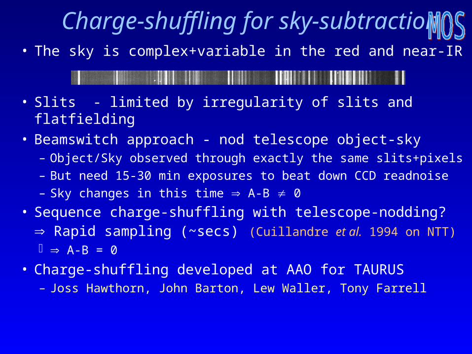
• Slits - limited by irregularity of slits and flatfielding• Beamswitch approach - nod telescope object-sky
– Object/Sky observed through exactly the same slits+pixels
– But need 15-30 min exposures to beat down CCD readnoise
– Sky changes in this time A-B 0
• Sequence charge-shuffling with telescope-nodding? Rapid sampling (~secs) (Cuillandre et al. 1994 on NTT) A-B = 0
• Charge-shuffling developed at AAO for TAURUS– Joss Hawthorn, John Barton, Lew Waller, Tony Farrell
• The sky is complex+variable in the red and near-IR

`Va et Vient’
`Nod and shuffle’
CCD controllerInstrumentSequencer
TelescopeDrives

Distant cluster project
• Goal: to measure star-formation across the face of z~0.3 clusters via H line (~8500Å observed)– (Glazebrook, Bower, Couch)
• Use LDSS++ with R6 blocking filter (8500Å/400Å)– Microslits - fit ~900 in to 9 arcmin FOV
• AC114 - 4 hour exposure Aug 1999– 848 targets
– short dispersed spectra of H + [NII]

AC114
9 arcmin

AC114 Mask

Detector
Spectrograph
Slit
The answer to life, the Universe and everything...
Multifibre spectroscopy

Multifibre spectroscopy
Drawbacks:•Fibres have to be configured in advance•Fibres have to be registered with sky--careful astrometry needed•Sky-subtraction less effective than multi-slit•Thus lower ultimate sensitivity
Advantages:•Maximises use of detector area (because of reformatting)•Greater freedom in placing fibres in telescope field
•no overlapping spectra•not limited by collimator field
•Can easily feed more than one spectrograph
Follow-up mode (j fixed--sort of).

Multifibre spectroscopy
•Bulk transmission losses low from 0.5m to 2.0m•Low-OH (“dry”) fibres excellent for > 0.55m•High-OH (“wet”) fibres good for > 0.35m•But OH absorption features at 0.73, 0.95 and 1.37m•New Heraeus STU fibre combines best of both
•Focal ratio degradation (FRD)•Result of modal coupling in the fibre•Can cause overfilling of the collimator
•Image scrambling•Complete for beams slower than f/5
Fibre properties
Multifibre spectroscopy
•Multifibre spectroscopy started in Dec 1979 with Medusa•20-fibre plug-plate system on Steward 2.3-m Cass focus•AAT’s FOCAP followed in 1981--up to 64 fibres•ESO OPTOPUS, UKST FLAIR followed•Plug-plates still in use at SLOAN (660 fibres)
•Individual actuator systems•Steward’s 32-fibre MX-- “fishermen-round-the-pond” (1987)•HET ~10-fibre (x,y) actuator system•Echidna 400-fibre spine system (Subaru)
•Pick-place systems•Autofib (AAT), Autofib-2 (WHT), 2dF, 6dF, OzPos etc.
Fibre positioners

2dF on the AAT
Light from telescope
2dF corrector2 FOV
ADC
Plate 0 - setting up
Plate 1 - observing
Robot gripper
Spectrographs
4 metres

2dF on the AAT
Two spectrographs
Robot positioner400 fibres

Robot positioning fibres

Fibres on Plate

Configure

2dfdr

2dF spectra

Extracted 2dF spectra

Nod and Shuffle for 2dF
(Glazebrook, Hawthorn, Farrell, Waller, Barton, Lewis)
• Nod telescope and charge-shuffle simultaneously– Object and sky observed through exactly the same fibres
and CCD pixels– Excellent sky subtraction
•
First demonstration for 2dF in July 1999
(see AAO Newsletter #90)
More detailed recent investigation by Cannon et al. (see latest AAO Newsletter)
Limitation: only use 1 CCD, 1/4 fibres, and spend 1/2 time on sky

2dF Nod and Shuffle
(July 1999)
Raw arc spectra Shuffled exposure

Results on cloudy sky
Raw
Normalsky
subtract
N&S
sky
subtract

6dF local history—Multi-fibre spectroscopy at UKST
1982: Dawe & Watson suggest ‘radical’ change
1985: FLAIR prototype in operation
1988: PANACHE upgrade
1992: FLAIR II in operation—but still manual
1998: AAT Board approves 6dF at ~$A0.6M

The 6dF instrument
Specification:•6-deg field-of-view pick-place fibre system•Off-telescope robot•150×7” science fibres •FLAIR spectrograph•Marconi 10242 CCD•4 acquisition fibres•Two field plate units •Turn-round ~20 min•Reconfig. time ~40m•Up to ~6 fields/night
S/g6dF

6dF Robot
(r, ) robot
positions on
spherical
field-plate.
Air-bearings
throughout;
pneumatic
gripper.

Gripper uses air-bearings for z-motion, jaws open/shut and frictionless rotation.
Robot assembly—gripper

Fibre buttons have extended cylindrical upper section so gripper collet can grasp them
Fibre buttons

Prisms are SF2, cylindrical (2mm dia.× 5.7mm long) with flat to allow fibre to be cemented on. Fibre/prism unit then cemented into button. (Accepts full f/2.5 beam.)

Field-plate unit
40 cm

Field-plate unit

Local History—Multi-fibre spectroscopy at UKST
1982: Dawe & Watson suggest ‘radical’ change
1985: FLAIR prototype in operation
1988: PANACHE upgrade
1992: FLAIR II in operation—but still manual
1998: AAT Board approves 6dF at ~$A0.6M
2001: 6dF commissioning begins Feb 2001

6dF commissioning team

6dF in action

UK Schmidt Telescope usage
Year 6dF Photo. CCD
2001 70% 20% 10%
2002 <90% Override 10%
2003 <90% Override 10%
2004 <90% Override 10%
~75% dedicated to 6dF galaxy survey
~15% available for non-survey spectroscopy
6dF operations

Summary
• Multi-object spectroscopy is cool
• LDSS++, 2dF and 6dF are fab
• Australia is a leading player
• Bonzer, mate