objective flux slurry fixtures nocolok®flux
TRANSCRIPT
NOCOLOK®Flux Dry Scrubber
Flux SlurryBrazing
Key observations
HF Generation
CoatingsProduct Fit up
Flux Application
Process Sequence Magnesium
HF Generation
Product Fit up
Welding
Welding
Soldering
Flux Application
Process Sequence
Process Sequence
Process Sequence
Fixtures
Flux SlurryBrazing Reactions
Brazing Reactions
Corrosion TestsTemperature Profile
Drying
Cleaning/Degreasing
Wettability
Wettability
WettabilityPreparation
ProductionWet fluxing
Objective
Objective
Objective
Reactions
Reactions
Magnesium
Magnesium
Magnesium
Magnesium
Dry Scrubber
Dry Scrubber
Dry Scrubber
Dry Scrubber
Brazing Sheet
Flame Brazing
Flux Spills
Flux Spills
Flux Spills
Flux Spills
Tempers
Coatings
Coatings
Coatings
Coatings
CoatingsCoatings
Coatings
HF GenerationProduct Fit up
Core alloys
Key observations
Key observations
Cladding Alloys
Agitation
Agitation
Agitation
Agitation
FixturesNOCOLOK®Flux
®
NOCOLOK® Encyclopedia

Solvay Special Chemicals
2 NOCOLOK® Encyclopedia ©Solvay Special Chemicals
Basic..........................................................................................................6
What is brazing? ......................................................................................6
What is welding? .....................................................................................6
What is soldering? ...................................................................................6
Process.Sequence....................................................................................7
Fluxing after assembly .............................................................................7
Flux Painting ............................................................................................7
Fixtures......................................................................................................8
Considerations ........................................................................................8
Permanent Fixtures ..................................................................................9
Cleaning ..................................................................................................9
Steel banding ..........................................................................................9
Transport of Dry Powder ........................................................................10
Cleaning/Degreasing.............................................................................11
Wettability ..............................................................................................11
Aqueous Cleaning .................................................................................12
Thermal degreasing ...............................................................................14
When do I need a surfactant? ................................................................15
Measuring Cleanliness ...........................................................................15
Flux.Application......................................................................................16
Role and Objective ................................................................................16
Flux loading and working mechanism ....................................................17
How to measure? ..................................................................................18
Slurry concentration ..............................................................................19
Wet fluxing ............................................................................................19
Electrostatic fluxing ................................................................................20
Over-fluxing.............................................................................................22
Consequences ......................................................................................22
Flux.Slurry...............................................................................................23
Preparation ............................................................................................23
Agitation ................................................................................................24
Water quality .........................................................................................25
Dumping ...............................................................................................26
Flux.Recovery.........................................................................................27
Recycle and reuse? ...............................................................................27
Content

Solvay Special Chemicals
3 NOCOLOK® Encyclopedia ©Solvay Special Chemicals
Content
Wastewater.............................................................................................27
Treatment ..............................................................................................27
Flux.Slurry...............................................................................................28
Transport ...............................................................................................28
Slurry.Concentration.Measurement.....................................................29
Density ..................................................................................................29
Continuous ............................................................................................30
Adjustment of Concentration .................................................................31
NOCOLOK®.Flux.....................................................................................33
Production .............................................................................................33
Composition ..........................................................................................33
Characteristics ......................................................................................34
Flux Transformations ..............................................................................35
Drying......................................................................................................37
Objective ...............................................................................................37
Brazing.Conditions.................................................................................38
Furnace atmosphere .............................................................................38
Dew Point Measurement .......................................................................39
Relationship between dew point and moisture content ..........................40
Time/Temperature.Profile......................................................................41
How to obtain? ......................................................................................41
Important criteria ...................................................................................42
Furnace.Atmosphere..............................................................................43
Conditioning the furnace ........................................................................43
HF.Generation.........................................................................................44
Mechanisms and sources ......................................................................44
Brazing.Reactions..................................................................................45
Reactions ..............................................................................................45
Flux.Residues..........................................................................................46
Characteristics ......................................................................................46
Post.Braze.Flux.Residue.and.Engine.Coolants...................................49
Key observations ...................................................................................49
Determining Dissolved Flux Levels in Coolants .......................................50
Other factors .........................................................................................51
Summary ...............................................................................................51

Solvay Special Chemicals
4 NOCOLOK® Encyclopedia ©Solvay Special Chemicals
Dry.Scrubber...........................................................................................52
Effluent treatment ..................................................................................52
Flame.Brazing.........................................................................................53
General Features ...................................................................................53
Hardware and consumables ..................................................................54
Automation ............................................................................................55
Magnesium..............................................................................................56
Effects on brazeability ............................................................................56
Improving brazeability ............................................................................57
NOCOLOK® Cs Flux ..............................................................................58
Degradation of microstructure ...............................................................59
Oxide.Film.Thickness.............................................................................60
Effect on brazing ...................................................................................60
Brazing.Sheet..........................................................................................61
Description and Microstructure ..............................................................61
Microstructure after brazing ...................................................................62
Aluminum Alloys ....................................................................................63
Core alloys ............................................................................................64
Cladding Alloys ......................................................................................65
Folded.Radiator.Tubes.(B-Tubes)..........................................................66
Brazing Issues .......................................................................................66
Aluminum.Metallurgy.............................................................................68
Tempers ................................................................................................68
Non-heat-treatable alloys .......................................................................68
Designations ..........................................................................................68
Heat treatable alloys ..............................................................................69
Designations ..........................................................................................69
Filler.Metal:.Diffusion.and.Erosion........................................................70
What to look for? ...................................................................................71
Examples ..............................................................................................72
Gap.Clearances......................................................................................73
Requirements ........................................................................................73
Content

Solvay Special Chemicals
5 NOCOLOK® Encyclopedia ©Solvay Special Chemicals
Product.Fit.up.........................................................................................75
Dimensional changes during brazing .....................................................75
Expansion of fixtures..............................................................................75
Hourglassing .........................................................................................75
Braze.Repair...........................................................................................76
Corrosion.Protection..............................................................................77
Influence of flux residues ........................................................................77
Long life alloys .......................................................................................77
Zn sacrificial protection ..........................................................................78
Coatings ................................................................................................79
Process related causes .........................................................................79
Corrosion.Tests.......................................................................................80
ASTM accelerated corrosion tests .........................................................80
History.of.NOCOLOK®.Flux.Brazing.....................................................81
Flux.Spills................................................................................................81
Bimetallic.Joining...................................................................................82
Brazing Al and Cu ..................................................................................82
Brazing Al and steel ...............................................................................82
NOCOLOK®.Sil.Flux................................................................................83
Principles ...............................................................................................83
NOCOLOK®.Li.Flux.................................................................................84
NOCOLOK®.Zn.Flux................................................................................86
NOCOLOK®.Sil.Flux,.NOCOLOK®.Li.Flux,..NOCOLOK®.Zn.Flux:..Combinations.and.Permutations?........................................................87
Content

Solvay Special Chemicals
6 NOCOLOK® Encyclopedia ©Solvay Special Chemicals
What is welding?
What is brazing?
What is soldering?
Welding is the joining of metals, usually with the addition of a filler metal which on cooling forms a metallurgical joint. The temperature required for welding is at the melting point of the metals to be joined (base metals). Unlike brazing and soldering, welding heat is typically
very localized - pinpoint - making weld-ing impractical to join metals over a large surface area.
See also:
Brazing is the joining of metals using a molten filler metal. On melting, the filler metal spreads between the closely fit-ted surfaces, forms a fillet around the joint and on cooling forms a metallurgi-cal bond. The filler metal melting tem-
perature is above 450 °C, but below the melting point of the metals to be joined.
See also:
Soldering is the joining of metals using a molten filler metal, which on cooling forms a metallurgical joint. The filler met-al melting temperature is below 450 °C and below the melting point of the met-als to be joined.
Basic
soldering
brazing
Return to Table of Contents
welding
soldering
Return to Table of Contents
welding
brazing
Return to Table of Contents
See also:

Solvay Special Chemicals
7 NOCOLOK® Encyclopedia ©Solvay Special Chemicals
Fluxing after assembly
Flux Painting
The process sequence really depends on the type of heat exchanger being manufactured. For heat exchangers such as radiators and condensers, the most common process sequence for ease of manufacturing is as follows:
core assembly
fixturing
degreasing
fluxing
drying
brazing
This is the preferred sequence as it mini-mizes handling of fluxed components and therefore flux drop-off. This se-quence also minimizes the handling of individual heat exchanger components.
See also:
Using a flux paint (flux + carrier + bind-er) allows certain heat exchanger com-ponents to be pre-fluxed and is helpful in the case where pre-fluxing internal components, baffles, side supports and even radiator headers and condenser manifolds is desired.
In this case there are numerous varia-tions possible in the process sequence depending on whether all heat exchang-
er components are pre-fluxed, whether only some components are pre-fluxed and traditional fluxing is still required on the fin pack and so on.
See also:
Process Sequence
process sequence
flux painting
Return to Table of Contents
process sequence
fluxing after assembly
Return to Table of Contents

Solvay Special Chemicals
8 NOCOLOK® Encyclopedia ©Solvay Special Chemicals
Fixtures are used to hold the braze as-sembly in place during brazing. Sur-faces with molten filler metal are very “greasy” and the fixtures need to hold the shape and tolerances during heat-up. Fixtures may also be used to sup-port attachments such as inlet or outlet tubes.
When considering the type or con-figuration of fixtures to use, there are a number of considerations to take into account. For example, differential ex-pansion between fixture and braze as-sembly increases part compression sig-nificantly during heat-up. One must be acutely aware of the differences in the coefficients of thermal expansion be-tween stainless steel and aluminum. Aluminum expands much faster than stainless steel and this must be taken into consideration when designing a fix-ture. This is important to prevent distor-tion of the heat exchanger at final braz-ing temperature.
Note that for those wishing to work in SI units, the conversion factor of [in/in °F x10-6] into [10-6 m/m K] is 1.8.
It is also important to note that molten filler metal dissolves steel and stainless steel. It is important to minimize contact with filler metal. It is also possible for alu-minum to braze to fixtures. It is therefore important to either use a brazing stop-off for surfaces in contact with aluminum or to oxidize the fixtures when new or af-ter cleaning. This can be done simply by running the fixtures through the brazing furnace.
See also:
Considerations
Fixtures
fixtures steel banding
cleaning permanent fixtures
Return to Table of Contents
Fig..1: Coefficient of Thermal Expansion for Various Metals

Solvay Special Chemicals
9 NOCOLOK® Encyclopedia ©Solvay Special Chemicals
Fixtures
Permanent Fixtures
Cleaning
Steel banding
The most common type of fixtures for heat exchanger manufacturing are per-manent fixtures, ones that are used over and over again. These are usually made and should be made from stainless steel to prevent rust contamination in the slur-ry tank. The preferred material for fix-tures is AISI 309 or 316, but most stain-less steel alloys are perfectly acceptable.
Springs may be used in the fixture to ap-ply a certain “holding” pressure to the heat exchanger during brazing. However, the technique of using springs seems to be less common than in the past. More
often now, fixtures are designed with fixed dimensions. The heat exchanger is compressed slightly and loaded into the fixture. When the source of com-pression is removed, the natural spring-back holds the heat exchanger in place against the fixture.
See also:
As flux builds up on permanent fixtures and may contaminate the flux slurry, it is necessary to routinely clean the fixtures to remove flux and other contaminants that may have accumulated. There is no convenient chemical cleaning method to remove flux residues. The most ap-propriate methods are by mechanical means such as wire brushing or grit-blasting, although reports of ultrasonic cleaning have also shown this to be a suitable cleaning method in some cases.
Brand new fixtures require oxidation to prevent sticking or even brazing to the work piece. This is easily accom-plished by running new fixtures through a braze cycle. Experience has shown that cleaned fixtures do not require re-oxidation.
See also:
An alternative to permanent fixtures is the use of disposable steel banding. Since mild steel can be used, material costs are kept to a minimum. Wax coat-ed mild steel bands are often used to prevent the banding material from rust-ing that can contaminate the flux slurry and discolor the heat exchanger. The steel bands are used only once and are disposed of after brazing.
Steel banding requires experimentation to determine the appropriate tension
and positioning. Thereafter, an automatic banding machine should be used to en-sure consistency.
See also:
fixtures steel banding
cleaning considerations
Return to Table of Contents
fixtures steel banding
considerations permanent fixtures
Return to Table of Contents
fixtures considerations
permanent fixtures cleaning
Return to Table of Contents

Solvay Special Chemicals
10 NOCOLOK® Encyclopedia ©Solvay Special Chemicals
Transport of Dry Powder
The following text provides some gen-eral information on powder transport (conveying) systems for handling NO-COLOK® Flux in bulk quantities. These recommendations are based on the ex-perience from Solvay’s flux production.
The first, and most important factor to consider, is the distance the powder needs to be conveyed. For short dis-tances, 0.3 – 3 meters (1 – 10 feet), a screw conveyor can be used. It is advis-able to keep a screw conveyor as short as possible! This equipment should be made of 316L SS and will see some abrasion over time. 316 SS has molyb-denum as an alloying element, which helps to extend the life of the screw and trough. Also, lining the trough with UHM-WPE (Ultra High Molecular Weight Poly-ethylene) sheet will reduce friction and wear.
For longer distances, i.e., up to 30 me-ters (up to 200 hundred feet), a dilute phase vacuum pneumatic transport sys-tem works well. There are many manu-factures of pneumatic transport systems world wide. It is simple and cost effec-tive. Because it is dilute and not dense phase, 304L SS pipes can be used from one point to the other. Such a system is set up as follows:
The vacuum filter receiver is an air/ sol-ids separation device. Such a system requires little maintenance. The piping needs to be of sufficient diameter to minimize wear and abrasion (7.5 – 10 cm; 3 – 4 inch). The elbows need to be long radius or “Sweep’s”. Such sweeps will need to be cleaned out every few years (depending on amount transport-ed through the pipe, humidity, etc.) and may need to be replaced over longer pe-riods of time (7 – 10 years) due to abra-sion wear.
See also:
Flux Powder
flux slurry
transport
Return to Table of Contents
Fig..2: Transport of Flux Powder

Solvay Special Chemicals
11 NOCOLOK® Encyclopedia ©Solvay Special Chemicals
Wettability
The concept of wettability must be un-derstood prior to any in-depth discus-sions on cleaning and degreasing. This is important since the type of cleaning method used determines whether the component surfaces will be wettable or non-wettable.
All aluminum components as-received are not water wettable. This means that water will not uniformly coat the surface when sprayed or dipped, but rather will bead up and run off, analogous to water
on a freshly waxed automobile. A more scientific explanation for determining whether an aluminum surface is wetta-ble or non-wettable is with contact angle measurements. If the contact angle (the angle that the liquid droplet makes with the solid substrate) is less than 90 de-grees, this is a non-wettable condition. A contact angle of greater than 90 degrees results in a wettable condition. Below is a pictorial representation of wettability:
A simple test for determining whether one has a wettable or non-wettable Al surface is the water dip test. A compo-nent is dipped in water and withdrawn. As described above, if the water beads up and runs off, the Al component is non-wettable. Conversely, if the water sheets and coats the surface uniformly, the component is wettable.
A wettable condition is preferred when applying a flux slurry to an Al compo-nent. Fortunately, the Al surface or the flux slurry can be made wettable and this depends on the actual degreasing method employed. The references be-low explain in more detail.
With actual flux slurry application, the differences between wettable and non-wetta-ble conditions are shown below:
Cleaning/Degreasing

Solvay Special Chemicals
12 NOCOLOK® Encyclopedia ©Solvay Special Chemicals
1 F. Makin, Betz Dearborn, T.A. Seminar Notes (1998)
Aqueous cleaning starts off with a con-centrated metal cleaning agent, which is subsequently diluted with water to 1% to 5% (v/v). The composition of a supplier’s cleaning solution is proprietary, but usu-ally contains a mixture of surfactants, detergents and active ingredients such as sodium carbonate that serves to el-evate the pH. Once diluted, the cleaning solution will typically have an elevated pH in the range of pH 9 to 12. There are acid based solutions, but appear to be less common.
The cleaning solution works best at hot-ter temperatures and is usually recom-mended to operate at 50 °C to 80 °C. Cleaning action is quicker at hotter solu-tion temperatures.
Cleaning takes place in a series of steps starting by dipping or spraying with the hot cleaning solution followed by a se-ries of hot and cold-water rinses. A typi-cal washer configuration would contain the following:1
1. Pre-wash: removes dirt and fines and some oils
2. Blow-off: removes much of the solution to prevent dilution and contamination of the next tank
3. First alkaline cleaner: main work station where most of the oils are removed
4. Blow-off
5. Optional second cleaner: removes the last of the oils
6. Blow-off
7. City water rinse: removes residual alkaline cleaner
8. Blow-off
9. DI water rinse: removes residual alkaline and city water salts
10. Blow-off
11. Send to fluxing station
The cleaning efficiency is generally a function of:
• Solution concentration
• Time
• Temperature
• Contact pressure
Aqueous Cleaning
Cleaning/Degreasing
Solvay Special Chemicals
13 NOCOLOK® Encyclopedia ©Solvay Special Chemicals
Cleaning/Degreasing
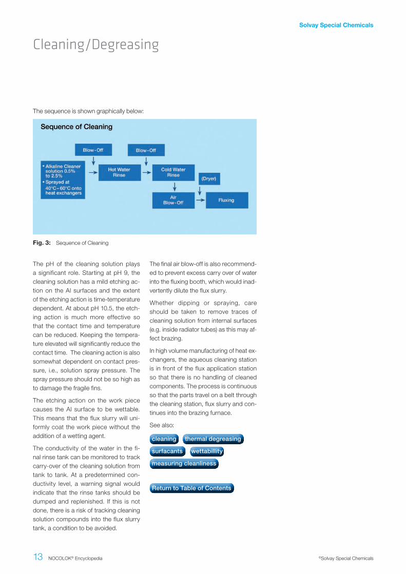
Fig..3: Sequence of Cleaning
The pH of the cleaning solution plays a significant role. Starting at pH 9, the cleaning solution has a mild etching ac-tion on the Al surfaces and the extent of the etching action is time-temperature dependent. At about pH 10.5, the etch-ing action is much more effective so that the contact time and temperature can be reduced. Keeping the tempera-ture elevated will significantly reduce the contact time. The cleaning action is also somewhat dependent on contact pres-sure, i.e., solution spray pressure. The spray pressure should not be so high as to damage the fragile fins.
The etching action on the work piece causes the Al surface to be wettable. This means that the flux slurry will uni-formly coat the work piece without the addition of a wetting agent.
The conductivity of the water in the fi-nal rinse tank can be monitored to track carry-over of the cleaning solution from tank to tank. At a predetermined con-ductivity level, a warning signal would indicate that the rinse tanks should be dumped and replenished. If this is not done, there is a risk of tracking cleaning solution compounds into the flux slurry tank, a condition to be avoided.
The final air blow-off is also recommend-ed to prevent excess carry over of water into the fluxing booth, which would inad-vertently dilute the flux slurry.
Whether dipping or spraying, care should be taken to remove traces of cleaning solution from internal surfaces (e.g. inside radiator tubes) as this may af-fect brazing.
In high volume manufacturing of heat ex-changers, the aqueous cleaning station is in front of the flux application station so that there is no handling of cleaned components. The process is continuous so that the parts travel on a belt through the cleaning station, flux slurry and con-tinues into the brazing furnace.
See also:
The sequence is shown graphically below:
cleaning thermal degreasing
surfacants wettabillity
measuring cleanliness
Return to Table of Contents

Solvay Special Chemicals
14 NOCOLOK® Encyclopedia ©Solvay Special Chemicals
Thermal degreasing works by elevating the temperature of the work piece so that lubricants present on the surfaces will be flashed off. This procedure only works with special types of lubricants known as evaporative or vanishing oils. Vanishing oils are light duty lubricants used mostly for the fabrication of heat exchanger fins, although they are now finding uses in the stamping and forming of other heat exchanger components. Lubricants not designed for thermal degreasing should not be used. These could leave behind thermal decom-position products and carbonaceous residues which have the potential to de-grade product appearance and acceler-ate corrosion.
The process of thermal degreasing typi-cally works as follows. After the heat ex-changers are assembled and fixtured, they are loaded either batch-wise into a specially built thermal degreasing oven, or continuously on a belt through a ther-mal degreasing station. In either case, the heat exchangers are exposed to a suitable time-temperature cycle to flash off the lubricants. The lubricant suppli-ers can recommend suitable cycles. The exhaust gases may need to be treated (scrubbed or incinerated) depending on local exhaust policies. The heat ex-changers are then fluxed after the ther-mal degreasing cycle.
Conventional thermal degreasing cycles normally produce a non-wettable sur-face. This means that the flux slurry
would require the addition of a surfac-tant to provide wettability for uniform flux deposition. It is known however that there are time-temperature cycles that do produce wettable surfaces on Al. The problem is that to achieve wet-tability in a reasonably short time, the temperatures must be quite high (e.g. 3 minutes at > 275 °C). Wettability can be achieved at lower temperatures, but require much longer times (e.g. 10 min-utes at 200 °C). There are some draw-backs with using a thermal degreasing cycle to achieve wettability. First, heat is an expensive utility, especially when the temperature required to flash off the lu-bricant is much lower than that required to achieve wettability. Secondly, there is a risk of oxidizing the surface of Al at higher temperatures. Nonetheless, heat exchanger manufacturers and lubricant suppliers are experimenting with time-temperature cycles and new lubricant packages to take advantage of this wet-tability crossover point on Al. In general however, it is still accepted that when thermal degreasing is used, a surfactant should be added to the flux slurry.
See also:
Thermal degreasing
Cleaning/Degreasing
cleaning aqueous cleaning
wettabillity surfactants
measuring cleanliness
Return to Table of Contents

Solvay Special Chemicals
15 NOCOLOK® Encyclopedia ©Solvay Special Chemicals
If the cleaning method leaves the sur-face of the work piece non-wettable, a wetting agent or surfactant should be added to the flux slurry. The surfactant works by lowering the surface tension of the water in the flux slurry, which will then cause the slurry to uniformly coat the work piece rather than beading up and running off. Surfactants are added to the flux slurry at very low concentra-tions, in the range of 0.05% up to 1% (v/v). Surfactants should be added to a fresh flux slurry incrementally to the point where wettability is just achieved. This can be tested by dipping a non-wettable component in the flux slurry tank after each incremental addition of surfactant. When the flux slurry uniform-ly coats the test piece, there is enough surfactant. This “dip test” can be used periodically check wettability in a used slurry. Excessive addition of surfactant
beyond recommended levels may affect brazeability, brazed appearance and corrosion performance. At the present time, there are no known quick and re-liable methods to determine surfactant concentrations in flux slurries.
There are appropriate low-foaming non-ionic surfactants in the marketplace for this application. In addition, there are automatic liquid dosing systems in the market which can be incorporated into wet fluxers working with automatic slurry replenishing.
See also:
There are a number of quick tests to determine if the heat exchanger is suf-ficiently cleaned. For the most part these tests are semi-quantitative and perhaps subjective as well, but they do provide a quick assessment of the cleanliness. The only way to truly quantify the surface cleanliness is to conduct more sophisti-cated and time consuming tests such as electron optical surface studies. Chemi-cal methods such as MEK extraction (methyl ethyl ketone) will also provide de-finitive results for organic contamination, but these are time intensive and require laboratory facilities.
Simpler.tests.include:1
• Measure the weight loss before and after cleaning. When the weight loss approaches zero, one can assume the surface is clean.
• Ultra violet (UV) lamp test is suitable for internal and external surfaces. Most organic compounds will glow under UV light would indicate incom-plete cleaning.
• Wipe the surface of aluminum with white paper. Any contamination on the surface of aluminum would stain the white paper.
• A coupon wettability test would indi-cate proper flux retention and distri-bution.
See also:
When do I need a surfactant?
Measuring Cleanliness
Cleaning/Degreasing
cleaning aqueous cleaning
thermal degreasing wettability
Return to Table of Contents
cleaning aqueous cleaning
wettability surfactans
thermal degreasing
Return to Table of Contents
1R.Evans, Calsonic Tech. Center, 1st International Congress Aluminium Brazing, Düsseldorf (May 2000)

Solvay Special Chemicals
16 NOCOLOK® Encyclopedia ©Solvay Special Chemicals
There is a natural protective oxide film on all Al surfaces. Even though the ox-ide film is very thin (100 Angstroms or less for wrought Al products), it is ex-tremely hard, tenacious and has a very high melting point. When an Al surface is scratched, the oxide reforms instanta-neously - this is why Al is said to be self-healing. It is this oxide, which gives Al its excellent corrosion properties.
This oxide film must be removed or dis-placed to allow brazing, hence a met-allurgical bond to occur between the metal surfaces. Once molten, the role of the flux is then to dissolve the oxide film on the Al surfaces to be joined and prevent re-oxidation during brazing. The flux wets the Al surfaces and allows the filler metal to flow freely into the joints by
capillary action. Upon cooling, the flux remains on the brazed component as a thin tightly adherent film, which need not be removed.
The objective of fluxing is therefore to apply a thin uniform layer on all active brazing surfaces. The flux should be ap-plied as thinly as feasibly possible with-out sacrificing brazeability. And lastly, the flux should be applied consistently and reliably from component to compo-nent.
See also:
Role and Objective
Flux Application
flux application
flux loading
Return to Table of Contents

Solvay Special Chemicals
17 NOCOLOK® Encyclopedia ©Solvay Special Chemicals
Based on empirical data, the minimum amount of flux required to dissolve a 100 Å oxide film is about 2.0 g/m2 (1 Å = 10 –10m = 1nm) in optimal brazing conditions. This flux load does not take into account losses to moisture, oxygen or poisoning of the flux by Mg alloy ad-ditions.
In practice however, the recommended loading for fluxing is 3 – 5 g/m2, uniform-ly distributed on all active brazing sur-faces. To visualize what 5 g/m2 flux load-ing might look like, think of a very dusty car. As the heat exchange manufacturer gains experience with his products, he may find that a little more is required for consistent brazing or that he can get away with a little less flux.
Upon melting, the flux flows and pen-etrates into micro-cracks in the alumi-num oxide layer. The cracks form during heat up due to the difference in thermal expansion between the oxide layer the base aluminum. Once it has penetrated the oxide layer, the flux appears to lift and separate the oxide from the base aluminum. Evidence has shown that the most of the oxide appears to float on top of the molten flux whereas some of the oxide is submerged and at least partially dissolved in the molten flux.
D. Sichen (Flux Reactions in Aluminum Brazing with Fluoride Fluxes, 1996) sug-gests the following equation to explain partial dissolution of the aluminum oxide in the molten flux:
Al2O3 [AlO2]- + [AlO]+
After brazing, the oxide is still there and is part of the flux residue. In addition, the aluminum surface will re-oxidize imme-diately including all the surfaces at the joints where flux residue is found.
Too little flux will result in poor filler metal flow, poor joint formation, higher reject rates, and inconsistent brazing. In other words, the process becomes very sen-sitive.
Too much flux will not affect the brazing results. However there will be pooling of flux which can drip on the muffle floor, the surface of the brazed product will be gray and there will be visible signs of flux residue. Furthermore, flux will accumu-late on fixtures more rapidly which then requires more frequent maintenance. More importantly yet, using too much flux will increase the process costs.
In some cases, heat exchanger manu-facturers use higher than recommend-ed flux loadings to mask furnace at-mosphere deficiencies. This should be viewed as a short-term solution and the furnace problems should be addressed.
See also:
Flux loading and working mechanism
Flux Application
flux application
role and objective
over-fluxing
Return to Table of Contents

Solvay Special Chemicals
18 NOCOLOK® Encyclopedia ©Solvay Special Chemicals
In the case of heat exchangers, the sur-face area being fluxed must first be de-termined. For ease of calculation, the louvers on the fin can be ignored. The radius on the fin can also be ignored. Imagine then the fin pulled out of the heat exchanger and straightened out to form one long strip. Similarly, the sur-face area of the slots in the header can also be ignored. Remember that in cal-culating the surface area of the heat ex-changer, there are 2 sides to every tube, 2 sides to every fin and 2 sides to the headers. The total surface area is then expressed in m2:
All dimensions are in meters (m) to yield a surface area in square meters.
HeaderAssuming it is a cylindrical (condenser) header:
SA (m2) = (2 x 3.14 x radius of header(m)) x length of header (m) x 2 headers
Assuming it is a radiator header:
SA (m2) = length of header (m) x width of header (m) x 2 (sides/header) x 2 (head-ers)
TubesSA(m2) = width of tube(m) x length of tube (m) x 2 (sides/tube) x total number of tubes
FinsIgnore the louvers in the fins
SA (m2) = width of fin (m) x (fin height (m) x number of fin legs/tube)
x 2 ( sides/fin) x total number of fins
An alternative to measuring the surface area of the fin is to use the weight meth-od (using 2700 kg/m3 as density of Al)
• Weigh the fins used for one compo-nent
• SA (m2) = weight (kg) / 2700 kg/ m3 / fin thickness (m)*2
Total Surface area in m2 = SA headers + SA tubes + SA fins
To determine the flux loading, a degreased and thoroughly dry heat ex-changer is weighed. The heat exchanger is then run through the fluxer, blow-off and dry-off section of the furnace. The heat exchanger is removed just prior to entering the brazing furnace and weighed again. The flux coating weight is then determined using the following formula:
To make sure that the flux loading was determined on a completely dry unit, run it through the dry-off section a second time and re-weigh.
See also:
How to measure?
Flux Application
flux application
flux loading
over-fluxing
Return to Table of Contents
Weight of unit fluxed and dried (g) - weight of unit un-fluxed (g)
Surface area (m2)

Solvay Special Chemicals
19 NOCOLOK® Encyclopedia ©Solvay Special Chemicals
The most often asked question when setting up a fluxing practice is what concentration of flux slurry to use. Un-fortunately, there is no one correct con-centration to use since it depends on many factors. There are in fact many other factors affecting flux loading and they must all be taken into consideration when targeting a certain level. First is the application method whether it be dip-ping, spraying or flooding. Even the type of spray will deposit more or less flux on
the component surfaces, depending on nozzle configuration (atomizing spray vs. shower effect). The component sur-face wettability, conveyor speed and the strength and volume of the air blow-off all play a role in controlling flux loading.
While the flux slurry concentration is im-portant, all other factors also contribute to control the flux loading. If any one factor is changed, the flux loading will change. The goal is to balance all fac-tors to achieve the desired flux loading.
See also:
In its simplest form, a slurry is held in a reservoir tank and continuously agitated to prevent settling. The slurry is pumped, usually with air-diaphragm pumps to the flux slurry cabinet where the heat ex-changers moving on a conveyor are sprayed with the slurry. After spraying, the excess flux slurry is blown off in a separate chamber with high volume air. The over spray and blown off slurry is re-cycled back to the reservoir tanks, again using air-diaphragm pumps.
Depending on the sophistication de-sired, a second flux spray chamber may be installed after the first chamber to deliver a higher concentration slurry to problem areas such as tube to header joints in condensers and radiators. This second spray chamber would have a separate flux delivery system and a sep-arate reservoir tank to contain the higher concentration flux slurry.
The components of the flux delivery system including reservoir and agita-tors should all be constructed of stain-less steel or chemically resistant plastics (nozzles for instance). There should be no mild steel or copper containing com-ponents – includes brass or bronze – in contact with the flux slurry. The sche-matic below shows the components of a generic fluxing station:
Note that splashing will occur inside the fluxing cabinet an cause an accumula-tion of dried flux on the walls. Therefore the cabinet is washed with water peri-odically to remove this accumulated flux. The frequency of this maintenance op-eration is up to the manufacturer, but it is good practice to perform it at least once at the end of each shift.
See also:
Slurry concentration
Wet fluxing
Fig..4: Generic Fluxing Station
Flux Application
flux application
determining
flux loading
Return to Table of Contents
flux slurry water quality
preperation dry fluxing
Return to Table of Contents

Solvay Special Chemicals
20 NOCOLOK® Encyclopedia ©Solvay Special Chemicals
Dry fluxing is a technology whereby the flux is electrostatically charged and ap-plied to grounded work piece, in our case a heat exchanger or individual heat exchanger components. The electro-static attraction causes a layer of flux to be deposited on the work piece. A typi-cal flux application system consists of a powder feed system, the electrostat-ic spray gun, the gun control unit, the grounded work piece and finally the flux recovery system.
The advantages of such a system over conventional wet fluxing are evident. Since the flux is applied dry, there is no need to prepare flux slurries, hence no need to monitor flux slurry concen-trations. There is also no wastewater generated therefore more environmen-tally friendly. The dehydration or dry-off section of the furnace may be eliminat-ed since the heat exchangers enter the
furnace already dry. However, one must keep in mind that there are some minor drawbacks. It is not possible to flux in-ternal surfaces and as such should not be considered for lines brazing differ-ent varieties of design models. Also, flux adhesion is not as good compared to that of wet fluxing. It is difficult to apply more flux to select areas such as tube-to-header or tube-to-manifold joints. Furthermore the flux also tends to ac-cumulate on the leading edges of the heat exchanger because of the Faraday cage effect. Dry fluxing lends itself best to parts with simple geometries.
Electrostatic fluxing
Flux Application

Solvay Special Chemicals
21 NOCOLOK® Encyclopedia ©Solvay Special Chemicals
The second type of powder feed system works on the principle of mechanical delivery or positive displacement. This means that the powder feed rate to the air pump is controlled by a screw or au-ger. The flux is contained in a main feed hopper and delivered mechanically at a controlled feed rate to the air pump. Powder flow is thus regulated by con-trolling the auger feed rate. This powder feed system does not rely on the flux be-ing fluidized. Nonetheless, modifications over conventional mechanical powder feed systems are still necessary to over-come the differences between the flux characteristics and conventional powder paints.
Powder.Feed.SystemsPresently, there are 2 types of powder feed systems on the market. The first type begins with the flux being fluidized in a hopper. Dry compressed air is fed through a porous membrane in the bot-tom of the hopper. The air rising through the volume of flux makes it behave like a fluid since the powder is essentially dilut-ed with air. A pick up tube attached to an air pump is extended in the fluidized flux. Powder flow is then regulated by con-trolling the air-flow to the pump which is then delivered through the feed sys-tem to the spray gun. This type of feed system works perfectly well for powder paints. However, the flux has very differ-ent physical characteristics than powder paints (particle size, morphology) and so is difficult to fluidize. This must be taken into consideration when the manufac-turer designs a powder feed system that relies on fluidization.
See also:
wet fluxing
Return to Table of Contents
Fig..5: Dry Fluxing Powder Fluidization
Fig..6: Dry Fluxing Mechanical Flux Transport
Flux Application

Solvay Special Chemicals
22 NOCOLOK® Encyclopedia ©Solvay Special Chemicals
Very often, heat exchanger manufactur-ers increase the flux loading on compo-nents to be brazed to compensate for furnace atmosphere or other process related deficiencies. The flux is an ex-cellent “band-aid” and can be used as such, but only while the true problems are located and rectified. Long term use of higher than recommended flux loads can lead to other problems.
Over fluxing causes more KAlF4 evapo-ration and condensation. This will load up the dry scrubber more quickly. White powder will accumulate more quickly on the curtains at the exit end of the fur-nace. If this is noticed, there is a very good chance that the dry scrubber is loading up more quickly.
There will be a more rapid build-up of the flux inside the furnace. This is a common issue with over fluxing where-by flux builds up on the muffle floor at the entrance to the cooling zone where it will solidify. This flux build up has been known to deflect the mesh belt.
There is more rapid build up of the flux on the fixtures which can significantly re-duce maintenance intervals.
Over-fluxing can lead to visible flux resi-due on the brazed heat exchanger which may increase the incidence of flux resi-due fall-off. Excess flux residue dulls the appearance of a brazed heat exchanger and can also accumulate in the gasket areas causing problems with seals. Too much flux residue will also inhibit surface treatments such as painting or conver-sion treatments.
See also:
Consequences
Over-fluxing
flux loading
Return to Table of Contents
Solvay Special Chemicals
23 NOCOLOK® Encyclopedia ©Solvay Special Chemicals
In the simplest operation, the lid is re-moved and flux is manually scooped out of the drum (with a large plastic scoop) and added to the flux slurry reservoir tank. The flux should always be add-ed to water and never scooped into an empty tank. Aerosolization should be controlled by a local exhaust ventilation system (LEV). The operator will likely need to wear a dust respirator and PVC gloves, goggles and an adequate pro-tective coverall.
For large volumes of flux slurry prepa-ration, it is also common to dump the entire drum contents into the reservoir with a forklift truck. Again, care should be taken to avoid dusting and aerosol-ization.
All slurries must be agitated to hold the flux particulate in suspension. Allow-ing the flux particles to settle out in the mixing tanks or containers will result in inconsistent flux loadings. During a shutdown period (maintenance, holi-days etc.), the agitators may be turned off. Upon start up, it must be ensured that all settled flux is brought back into suspension prior to starting the fluxing operation.
Preparation
Flux Slurry
Solvay Special Chemicals
24 NOCOLOK® Encyclopedia ©Solvay Special Chemicals
Flux Slurry
Since the flux is insoluble in water and the goal is to keep the flux in suspen-sion, the natural tendency is to use high agitation speeds which creates high shear forces. The high shear forces will break up particles of flux and over time (even a few hours), shift the particle size distribution to smaller particles, even to the sub-micron range. These very small particles tend to be “sticky” and when collected in one place, will acquire a gel like appearance. Furthermore, once the flux has acquired this sticky property, it is very difficult to bring this flux back in suspension after a shut-down period.
These effects may be seen even if the speed of the agitator has not changed, but the slurry consumption has de-creased (e.g. one less work shift per day). In other words, the same flux is being agitated for a longer time than be-fore and therefore may be shifting to a smaller particle size as a result of the in-creased residence time in the tote.
The key to agitation for flux slurries is low speed – low shear agitation to just keep the flux in suspension. Faster is definitely not better when it comes to keeping the flux slurry suspended.
Flux which has acquired a gel like con-sistency caused by high shear stresses may lead to strainer clogging. Even if the
individual particles are small enough to pass through the mesh, once one par-ticle sticks to the screen, others will stick to it and eventually accumulate to such an extent as to clog the strainer. Gelled flux is very difficult to bring back into suspension because it does not break up easily – the flux sticks to itself. This gelled flux will clog a small mesh size strainer in no time at all. The stickiness of sub-micron particle size flux has been associated with many blockages and is often seen to clog nozzles.
Large agglomerates are most often formed by the flaking off of flux that has dried on the walls of the spray cabinet or other nearby structures such as ex-haust hoods. The best practice to avoid the formation of these agglomerates is to have a regular clean-out procedure. When this practice is not carried out, flux solids will settle out within individual droplets and form clumps or agglomer-ates. These agglomerates can be very hard and are also often associated with blockages.
See also:
Agitation
flux slurry
concentration measurement
Return to Table of Contents

Solvay Special Chemicals
25 NOCOLOK® Encyclopedia ©Solvay Special Chemicals
De-ionized (DI) or reverse osmosis (RO) water is recommended to make up the flux slurries. This is to avoid long-term accumulation of mineral deposits in the flux delivery system that can cause blockage of nozzles and /or inadvertent-ly drop on the heat exchanger. Further-more, local plant or city water may con-tain ppm levels of contaminants such as chloride and copper that are detrimental with respect to corrosion performance. Other contaminants may also be present which can affect brazing. Furthermore, to avoid any seasonal variations in water quality, to avoid variations in water qual-ity between manufacturing locations and so on, it is highly recommended that DI or RO water is used to make us flux slur-ries.
In general, it is difficult to comment on potential effects of trace impurities in the flux slurry water without knowing more details about the character of the con-tamination. There may be only very lit-tle influence on the brazing results even with 1000 µS conductivity. However, it is necessary to perform a chemical analy-sis of the water for further evaluation in each case.
The use of deionized water has always been recommended to prevent scale build up in the flux delivery system. Re-
verse osmosis (RO) water is also used successfully. There are no Solvay rec-ommendations on conductivity or maxi-mum hardness values (except those related to the calcium levels as listed be-low). The only reference Solvay can pro-vide is the conductivity of the de-ionized water used at our Technical Services and Analytical Department in Hanover, which is below 0.2 µS.
As far as we know, no scientific study was yet conducted to determine water quality requirements for aluminum braz-ing. In collaboration with Alcan, Solvay has established guidelines for maximum impurity limits for water quality based on contamination which might interfere with brazing or cause discoloration of the brazed parts:
Calcium <0.1% (1000 ppm)
Barium <0.05% (500 ppm)
Sodium <0.5% (5000 ppm)
Iron <0.02% (200 ppm)
Titanium <0.1% (1000 ppm)
Silicon <0.05% (500 ppm)
Lead <0.05% (500 ppm)
For Chloride a maximum of 0.02% is specified (corrosion problems). Based on experiences at some customer loca-tions with post braze odor in the past, Sulfates should be below 0.02%. Phos-phates can cause problems with post braze odor too, due to the potential for-mation of PH3. Silicates are known to interfere with flux activity. Borates and Silicates can cause black spots on post braze flux residue.
Residual hydrocarbons on all aluminum surfaces should be limited to the lowest level possible, due to the potential for-mation of carbonaceous residue and the long term corrosion problems caused by this residue. The same applies to all oth-er carbon containing trace impurities in the system.
Most of the above information refers to flux and flux slurry contamination, How-ever, it also relates to other additives and chemicals in the process, particularly when those additives cannot be,- or are not-, removed from the fluxed compo-nent prior to reaching brazing tempera-ture
See also:
Water quality
Flux Slurry
flux slurry
preparation
wet fluxing
Return to Table of Contents

Solvay Special Chemicals
26 NOCOLOK® Encyclopedia ©Solvay Special Chemicals
With continuous use, a flux slurry will eventually become contaminated. So far, there is no data that correlates the level of accumulated contaminants with poor brazing. Therefore, it is better to be on the safe side rather than wait till the number of rejects rise due to a con-taminated or dirty slurry. It is therefore recommended that a slurry should be dumped when there is visual evidence of contamination. If there is an oil slick floating on top of the slurry in the reser-voir or when it is discolored, the slurry should be dumped and replaced with fresh slurry. Alternatively, to avoid mis-judging the quality of slurry visually, the slurry could be dumped at regular in-tervals, especially if the manufacturer knows that the cleanliness of the heat exchangers entering the fluxing booth is not ideal. Experience will dictate how of-ten the slurry should be dumped.
Note however that some heat exchanger manufacturers almost never dump their flux slurries or if they do it might be on-ly once per year. This is only the case when the heat exchangers are very well degreased prior to entering the fluxing booth and efforts are made to avoid un-due contamination of the slurry. Simply keeping the cover closed on the slurry tank reservoir will keep out airborne con-taminants and lengthen the slurry life.
See also:
Dumping
wastewater
flux application
wet fluxing
Return to Table of Contents
Flux Slurry
Solvay Special Chemicals
27 NOCOLOK® Encyclopedia ©Solvay Special Chemicals
Around the flux slurry preparation sta-tion or around the perimeter of the flux-ing booth, there will inevitably be some flux on the floor. The inclination is to sweep up this flux and throw it into the flux slurry reservoir or back into the flux drum. This action should be avoided at all costs. Any flux that falls on the floor should be disposed of promptly. The reason is that there are too many con-taminants in a manufacturing environ-
ment that can affect brazing or cause other damage. Cigarette butts, paper clips, dust, dirt, oil, paper and so on can all have very damaging effects to the flux delivery system and on the brazed prod-ucts. If the flux is on the floor, dispose of it and do not reuse it.
See also:
Return to Table of Contents
In recent years, the topic of what to do with wastewater from fluxing operations has gained a lot of attention in light of heightened environmental awareness and compliance. Years ago, wastewa-ter from cleaning slurry booths, waste flux slurries etc. were simply diluted and dumped down the drain. Some manu-facturers are still following this practice, but it is become less and less common. Today, the heat exchanger manufac-turers are faced with what to do with wastewater more and more.
Some manufacturers collect the waste slurries and effluent from cleaning out the fluxing stations and allow the flux to settle out. The water phase is then de-canted and collected until a sufficient volume is collected. At that point, a waste disposal company is called in to collect and treat the contaminated wa-ter. This is an expensive, but in many cases a necessary option.
If the collected water is relatively clean and not contaminated with oil, it may be
reused to top up flux slurries. The only problem here is that one must be cer-tain that there are no other contaminants in the wastewater other than flux ions. If there are other contaminants (and there almost certainly will be), tests should be performed to ensure that these will not in any way interfere with the brazing pro-cess.
Solvay Fluor also developed a continu-ous process to reuse and recycle waste-water in a fluxing operation. It is based on the principles described above, only in a continuous fashion.1
See also:
Recycle and reuse?
Treatment
Flux Recovery
Wastewater
Flux slurry
transport
Return to Table of Contents
1Lauzon, D.C., Swidersky, H.W., “Methods for Eliminating Wastewater from Flux Slurries in Non-Corrosive Flux Brazing”, VTMS 2001-01-1764, pp 649-654, 2001.
Solvay Special Chemicals
28 NOCOLOK® Encyclopedia ©Solvay Special Chemicals
In a flux delivery system, the distances that the flux slurry has to travel is often very short and there is no time for the flux slurry to settle out in the lines or header pipe of the nozzle array. However, if the flux slurry must be conveyed over long distances, to the waste water treatment site at the other end of the plant for in-stance, then great care must be taken to prevent the lines, drains, pipes and troughs from becoming clogged with settled out flux. The flux slurry is a sus-pension and unless continuously agitat-ed, the flux will eventually settle out.
If the flux slurry must be conveyed over long distances, it is perhaps better to separate the flux and water with some sort of filter arrangement in the neigh-
borhood of the fluxing station. The solids can be collected near the fluxing station and the particulate free wastewater can then be easily transported.
A second option is to transport the used flux slurries batchwise (in drums) to the treatment facility or where ever desired. This eliminates all concerns about flux settling out in troughs or other parts of the plumbing system.
See also:
Transport
Flux Slurry
wastewater treatment
flux powder transport of dry powder
Return to Table of Contents
Solvay Special Chemicals
29 NOCOLOK® Encyclopedia ©Solvay Special Chemicals
Slurry Concentration Measurement
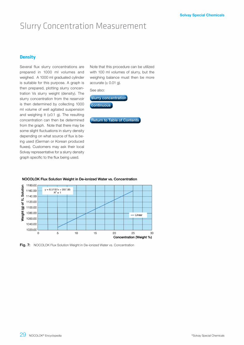
Several flux slurry concentrations are prepared in 1000 ml volumes and weighed. A 1000 ml graduated cylinder is suitable for this purpose. A graph is then prepared, plotting slurry concen-tration Vs slurry weight (density). The slurry concentration from the reservoir is then determined by collecting 1000 ml volume of well agitated suspension and weighing it (±0.1 g). The resulting concentration can then be determined from the graph. Note that there may be some slight fluctuations in slurry density depending on what source of flux is be-ing used (German or Korean produced fluxes). Customers may ask their local Solvay representative for a slurry density graph specific to the flux being used.
Note that this procedure can be utilized with 100 ml volumes of slurry, but the weighing balance must then be more accurate (± 0.01 g).
See also:
Density
Fig..7: NOCOLOK Flux Solution Weight in De-ionized Water vs. Concentration
slurry concentration
continuous
Return to Table of Contents
Solvay Special Chemicals
30 NOCOLOK® Encyclopedia ©Solvay Special Chemicals
Slurry Concentration Measurement
There are continuous inline slurry con-centration measurement devices avail-able in the market. They work on a va-riety of principles including ultrasonic, photoelectric, laser etc. Manufacturers of fluxing equipment can detail some op-tions. It has been reported that some in-line measurement devices are not en-tirely reliable due to the nature of the flux slurry. The flux must not be allowed to settle while a measurement is being tak-en or false readings will occur. Further-more, bubbles in the slurry caused by severe agitation or surfactants will also affect the reading. Work is being done in this area to improve these devices for use with flux slurries.
Density transducer devices have been shown to work well for in-line slurry con-centration measurements. The sensor of the density transducer is an oscillat-ing element in the form of a tube bent
into a tuning fork. The liquid to be mea-sured passes continuously through this element.The tuning fork is excited elec-tromagnetically by an excitation coil, and it oscillates at its natural frequen-cy. Changes in the density of the liquid changes in the tuning fork oscillation frequency. This change in frequency, sensed by a pick-up coil, represents the measurement effect. An additional built-in resistance thermometer measures the process temperature, which can also be used to equalize the temperature influ-ence in the transducer.
See also:
Continuous
slurry concentration
measurement
densitiy
Return to Table of Contents

Solvay Special Chemicals
31 NOCOLOK® Encyclopedia ©Solvay Special Chemicals
For experienced workers, adjusting the flux slurry concentration is almost sec-ond nature. After measuring the flux slurry concentration by whatever meth-od, experienced workers know how much flux and water to add to bring it back to the desired concentration – all by eye. For inexperienced workers, this can be a daunting task. The information provided in this section shows a sys-tematic and mathematical approach to adjusting flux slurry concentration when using the density measurement method. It is detailed for the sake of clarity.
Flux.Slurry.Concentration.ChartThe chart below shows the how the density of one liter of flux slurry varies with concentration. Note that there may be some slight fluctuations in slurry den-sity depending on what source of flux is being used (German or Korean pro-duced fluxes). Customers may ask their local Solvay representative for a slurry density graph specific to the flux being used. For this discussion the source of flux is irrelevant as it is meant to show how the calculations are performed.
The equation of the line as calculated is:
y.=.6.5197x.+.997.95
where y is the weight (g) of 1L of slur-ry and x is the slurry concentration (% w/w).
If you have the weight of the 1L of slur-ry, then using the equation of the line instead of reading from the graph, the slurry concentration (x) can be calculat-ed as follows:
x.=.(y.–.997.95)
6.5197
Preparation. of. Initial. Flux. Slurry.BathAssuming the total volume of the flux slurry bath is 200L, then using the equa-tion of the line shown above, the weight of flux and water required to make up 200L can be calculated as follows:
y.=.(6.519x.+.997.95).·.200
For a 17% slurry concentration (x = 17), the total weight of slurry required is:
y.=.(6.519.·.17.+.997095).·.200
y.=.221754.g.total.slurry
Adjustment of Concentration
Slurry Concentration Measurement
Fig..8: NOCOLOK Flux Solution Weight in De-ionized Water vs. Concentration

Solvay Special Chemicals
32 NOCOLOK® Encyclopedia ©Solvay Special Chemicals
For 17% flux slurry concentration, the weight of flux (x) required is:
0.17.=.x.g.flux./.221754
x.=.37698.g.flux.=.37.698.kg.flux
The weight of water required is therefore:
Weight.of.water.=.221754.g.total.slurry.–.37698.g.of.flux
=.184055.g.=.184055.ml.water.=.184.055.L.water
Adjusting.Flux.Slurry.ConcentrationMany of our customers, including some of the largest heat exchanger producers in the U.S., adjust their flux slurry con-centrations “by eye”. That is, the opera-tors have enough experience to make adjustments - so many scoops of flux + so many liters of water - without using any mathematical formulas. Until experi-ence is gained on your side, it might be best to make adjustments according to a formula. Below is a sample calculation to show how to bring the slurry concen-tration of 1L of slurry from 10% to 15%:
From the graph or the equation of the line, you have determined that you have a 10% (w/w) flux slurry. For 1 liter of flux slurry, this can be expressed as follows:
0.10.=.(0.1.kg.flux)./.(0.1.kg.flux.+.0.9.kg.H2O)
or
0.10.=.(0.1.kg.flux)./.(1.0.kg.total)
Now you want to make the adjustment up to 15%, but you don’t know how much more flux to add. Let this un-known weight of flux be represented by x:
0.15.=.(0.1.kg.+.x)./.(1.0.kg.+.x)
Now just solve for x (leaving units out for simplicity)
0.15.(1.0.+.x).=.0.1.+.x
0.15.+.0.15x.=.0.1.+.x
0.15.–.0.1.=.x.–.0.15x
0.05.=.0.85x
x.=.0.0588.kg
Therefore, an extra 0.0588 kg of flux / li-ter of flux slurry is needed to bring up the slurry concentration from 10% to 15%. And so you must know the total volume of flux slurry in the tote before making the adjustment. If for example you have 100 liters of flux slurry in the tote at the time you made the measurement, then:
0.0588.kg/L.x.100L.=.total.weight.of.flux.required.to.make.the.adjust-
ment
A similar calculation can be made if the flux slurry requires to be diluted. For ex-ample, if the flux slurry requires to be di-luted from 15% (w/w) to 10% (w/w), then water will have to be added. For 1 liter of slurry, the calculation is:
0.10.desired.conc..=.(0.15.kg.flux)./.(1.0.kg.total.+.xwater.to.be.added)
Solving for x (ignoring units):
0.10.(1.0.+.x).=.0.15
1.0.+.0.10x.=.0.15
x.=.0.05/0.10.=.0.5.kg.water
Therefore, 0.5 kg water/liter of slurry is required to bring the concentration from 15% to 10%.
See also:
Slurry Concentration Measurement
density
continuous
Return to Table of Contents

Solvay Special Chemicals
33 NOCOLOK® Encyclopedia ©Solvay Special Chemicals
NOCOLOK® Flux
NOCOLOK® Flux is produced in the liq-uid phase using Al(OH)3, HF and KOH as raw materials. The flux is precipitated out of solution, separated from the liq-uid phase and dried with strict process control. The stringent process toleranc-es and a variety of quality control pro-cedures produces a flux of the highest quality and consistency. The result is a fine white powder consisting primarily of
the potassium fluoroaluminate salts of the general formula K1-3AlF4-6 where a water of crystallization may be present.
See also:
NOCOLOK® Flux is a mixture of potas-sium fluoroaluminates:• KAlF4 (70 – 80%)
• K2AlF5 · H2O and K2AlF5 (20 –30%)
K2AlF5 exists in different crystallograph-ic forms:
• K2AlF5 · H2O
• K2AlF5 (phase I or α-phase)
• K2AlF5 (phase II or β-phase)
The ratio of the various crystallographic forms of K2AlF5 depends on the dry-ing conditions during flux production. It is worthwhile noting that in a flux slurry most of the K2AlF5 is present as K2AlF5 · H2O.
During brazing the flux undergoes physi-co-chemical transformations
Production
Composition
NOCOLOK® Flux
chraracteristics
Return to Table of Contents

Solvay Special Chemicals
34 NOCOLOK® Encyclopedia ©Solvay Special Chemicals
NOCOLOK® Flux
• Melting point range is 565°C to 572°C.
This is below the melting point of filler metal (577°C)
• Particle size distribution – slurry grade (NOCOLOK® Flux)
X50: 2 – 6 µm. This provides for good slurry characteristics while minimizing dust formation during handling.
• Particle size distribution – electro-static application (NOCOLOK® Flux Drystatic)
X50: 3.5 – 25 µm. This provides for good fluidization and trans- port properties which are re- quired when using electro- static application equipment. The fraction of smaller particles provides for good flux adhesion on the heat exchanger.
• Rated non-hazardous according to current regulations
Nonetheless, dust formation should be avoided.
• Non-hygroscopic
The only reaction of NOCOLOK® Flux with moisture is the rehydra- tion of phase I K2AlF5 to K2AlF5 · H2O. In the drying step of the NOCOLOK® Flux production, most of the K2AlF5 · H2O is converted into K2AlF5 phase I and only a small fraction of K2AlF5 phase II. Phase I K2AlF5 in the flux most likely will rehydrate within six months after production. The total difference of losson-heating analysis related to the rehydration of phase I K2AlF5 after this period is in average 0.5% without affecting the visible material appearance. As far as we know, there is no change in any chemi- cal or physical flux characteristic related to this effect.
Physical adsorption of moisture under humid conditions is an absolutely normal physical effect for a powder with large surface area. The flux has a very low water solubility and it will not liquefy in air by attracting humidity. NOCOLOK® Flux does not react with moisture and is not hygroscopic.
Since the flux is non-hygroscopic, it has an indefinite shelf life.
• Non-corrosive
The flux does not react with aluminum whether in its solid or molten state. It only reacts with the oxide on aluminum and only does so when the flux is at least partially molten.
• Low water solubility.
The flux is very slightly soluble in water where the solubil- ity is in the range of 1.5 – 4.5 g/m2. There is no chemical reaction with water in solution. The slurry life is therefore theoreti- cally in definite.
• Flux residues
The flux residues are non- corrosive and there is no inter- action with coolants, refriger-ants, moils and lubricants. Consequently, there is no need for flux residue removal.
See also:
Characteristics
NOCOLOK® Flux
production
Return to Table of Contents

Solvay Special Chemicals
35 NOCOLOK® Encyclopedia ©Solvay Special Chemicals
NOCOLOK® Flux is a mixture of po-tassium fluoroaluminates. It consists mainly of potassium tetra-fluoroalumi-nate (KAlF4), and also contains potas-sium penta-fluoroaluminate (K2AlF5). K2AlF5 exists in different modifications: potassium penta-fluoroaluminate hy-drate (K2AlF5 · H2O), and hydrate-free (K2AlF5).
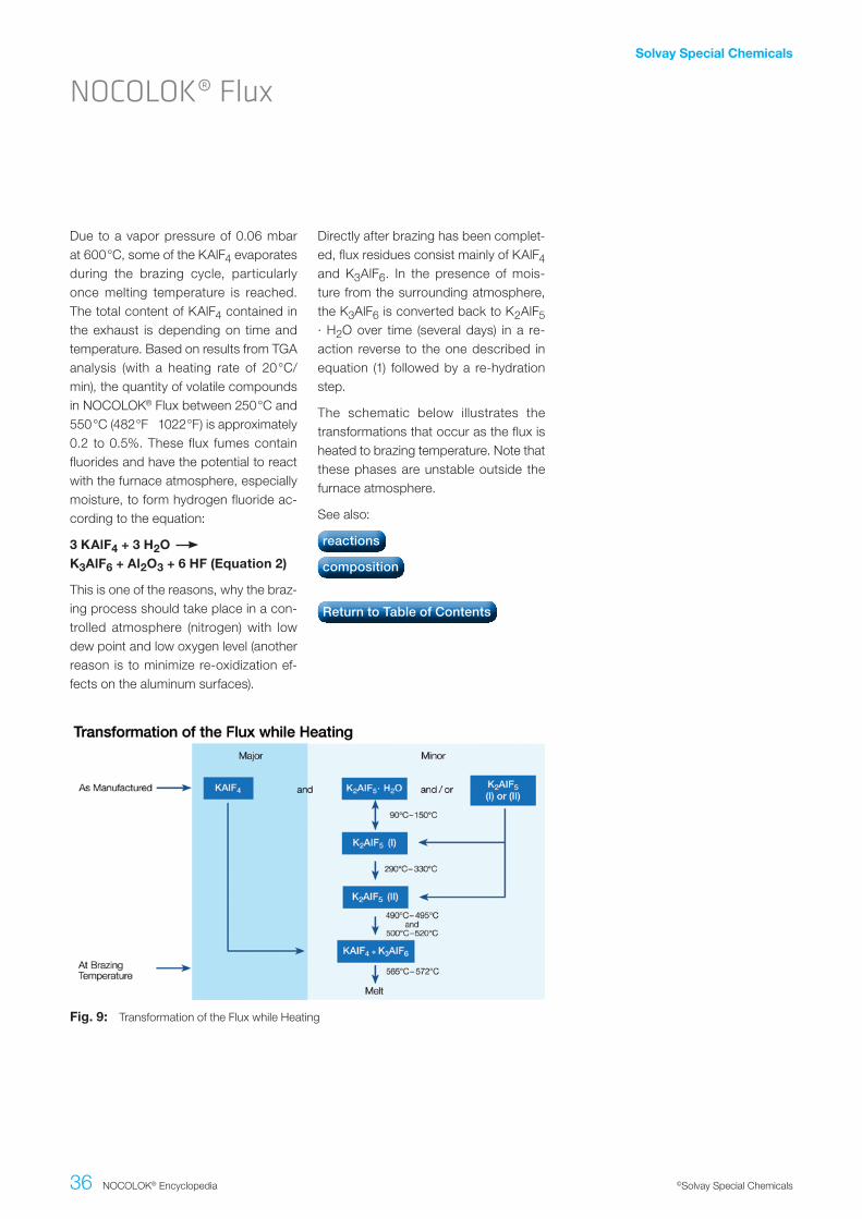
During the brazing process, the material undergoes essential physico-chemical alterations. While the chief component, KAlF4, is simply heated up, the com-pound K2AlF5 · H2O begins to lose its crystal water from 90°C (195°F) on. When the temperature is further in-creased within the ranges of 90° 150°C (195°F 302°F), and 290°C 330°C (554°F 626°F), two different crystallographic (structural) modifications of K2AlF5 are formatted.
When the furnace temperature is raised above 490°C (914°F), K2AlF5 begins to react chemically. According to the equa-tion:
2.K2AlF5..........KAlF4.+.K3AlF6.(Equation1)
the exact amount of potassium hexa-fluoroaluminate (K3AlF6) necessary for a eutectic flux composition (i.e. mix-ture of two or more substances which has the lowest melting point; see phase diagram) is obtained from the original K2AlF5 content. At brazing tempera-ture, the resulting flux composition has a clearly defined melting range of 565°C to 572°C (1049°F 1062°F). The flux melts to a colorless liquid.
Flux Transformations
NOCOLOK® Flux
Solvay Special Chemicals
36 NOCOLOK® Encyclopedia ©Solvay Special Chemicals
Fig..9: Transformation of the Flux while Heating
Due to a vapor pressure of 0.06 mbar at 600°C, some of the KAlF4 evaporates during the brazing cycle, particularly once melting temperature is reached. The total content of KAlF4 contained in the exhaust is depending on time and temperature. Based on results from TGA analysis (with a heating rate of 20°C/min), the quantity of volatile compounds in NOCOLOK® Flux between 250°C and 550°C (482°F 1022°F) is approximately 0.2 to 0.5%. These flux fumes contain fluorides and have the potential to react with the furnace atmosphere, especially moisture, to form hydrogen fluoride ac-cording to the equation:
3.KAlF4.+.3.H2O........K3AlF6.+.Al2O3.+.6.HF.(Equation.2)
This is one of the reasons, why the braz-ing process should take place in a con-trolled atmosphere (nitrogen) with low dew point and low oxygen level (another reason is to minimize re-oxidization ef-fects on the aluminum surfaces).
Directly after brazing has been complet-ed, flux residues consist mainly of KAlF4 and K3AlF6. In the presence of mois-ture from the surrounding atmosphere, the K3AlF6 is converted back to K2AlF5 · H2O over time (several days) in a re-action reverse to the one described in equation (1) followed by a re-hydration step.
The schematic below illustrates the transformations that occur as the flux is heated to brazing temperature. Note that these phases are unstable outside the furnace atmosphere.
See also:
NOCOLOK® Flux
reactions
composition
Return to Table of Contents

Solvay Special Chemicals
37 NOCOLOK® Encyclopedia ©Solvay Special Chemicals
The sole purpose of the dry-off section of the furnace is to remove the water from the fluxing operation. The amount of water carried into the dry-off oven de-pends on the flux slurry concentration – more dilute slurries carry in more water. One must also be aware of water on in-ternal surfaces of heat exchangers such as inside radiator tubes. All surfaces should be completely dry before enter-ing the brazing furnace. The following procedure can be used to determine if the product is completely dry:
1. Remove a unit exiting the dry-off oven and weigh it (W1). Be careful not to remove any flux.
2. Run the unit through the dry-off ov-en a second time and reweigh (W2).
3. Weight loss of water = W1 – W2
Any appreciable weight loss requires adjustment in dry-off settings, usually the maximum temperature. The user will have to set his own criteria for accept-ability. Note also that this test should be repeated when switching to a different product with a different configuration or weight.
One component of the flux is hydrated, also known as the water of crystalliza-tion. The flux component is K2AlF5 · H2O. The water of hydration is also re-moved in the dry off section at about 130°C. Note however that re-hydration will occur and so it is best to braze im-mediately.
The target temperature should be about 200°C. This refers to the temperature that the part reaches and not the fur-nace atmosphere temperature. Note also that there is a potential for oxida-tion in a moist atmosphere over 300°C. The temperature of the heat exchanger should never approach 300°C in the dry off oven.
When running a dry process with pre-fluxed (paint fluxed) parts the dry off may serve as a debindering furnace. With lit-tle moisture in the furnace atmosphere, it is possible to set the dry off up to 400°C without harmful occurrence of aluminum oxidation.
See also:
Objective
Drying
flux loading
how to measure
Return to Table of Contents

Solvay Special Chemicals
38 NOCOLOK® Encyclopedia ©Solvay Special Chemicals
The recommended furnace atmosphere conditions necessary for good brazing are as follows:
• Dew point: ≤ –40°C
• Oxygen: < 100 ppm
• Inert gas: nitrogen
The most common source of nitrogen is that generated from liquid nitrogen stor-age tanks. A typical nitrogen gas specifi-cation from a liquid source indicates that the moisture content is < 1.5 ppm (dew point = –73°C) and an oxygen level of < 3 ppm. In brazing furnaces however, the normal atmospheric operating con-ditions almost always exceed incoming nitrogen contaminant levels. This is due to water and oxygen dragged into the furnace by the incoming products, by the stainless steel mesh belt and by the potential back-streaming of factory at-
mosphere through the entrance and exit of the furnace. The latter will occur when the exhaust and incoming nitrogen are not properly balanced.
Many furnaces are equipped with dew point and oxygen measurement devices. It is important that the measurements are taken in the critical brazing zone of the furnace because this is where these impurities will reach their lowest concen-trations. Measuring dew point or oxygen levels anywhere else in the furnace may be of academic interest, but will not rep-resent actual brazing conditions.
See also:
Furnace atmosphere
Brazing Conditions
temperature profile
dew point measurement
Return to Table of Contents

Solvay Special Chemicals
39 NOCOLOK® Encyclopedia ©Solvay Special Chemicals
Measuring the moisture content in the critical brazing zone of the furnace has always been a key indicator of the qual-ity of the brazing atmosphere. Moisture can substantially influence the quality and appearance of the brazed heat ex-changer as well as the first time through braze quality (% rejects).
Chilled.Mirror.TechnologyOne of the more common principles of measuring dew point is using chilled mirror technology. The measurement of the water vapor content of a gas by the dew point technique involves chill-ing a surface, usually a metallic mirror, to the temperature at which water on the mirror surface is in equilibrium with the water vapor pressure in the gas sample above the surface. At this temperature, the mass of water on the surface is nei-ther increasing (too cold a surface) nor decreasing (too warm a surface).
In the chilled-mirror technique, a mirror is constructed from a material with good thermal conductivity such as silver or copper, and properly plated with an inert metal such as iridium, rubidium, nickel, or gold to prevent tarnishing and oxida-tion. The mirror is chilled using a ther-moelectric cooler until dew just begins to form. The temperature at which dew is formed on the mirror is displayed as the dew point.
The advantage of the chilled mirror dew point meter is that it is an absolute mea-surement with high precision. However, this measurement technique is sensitive to pollutants and corrosive contaminants which, in the brazing process, include KAlF4 condensation and trace amounts of HF gas. Consequently, the mirror re-quires frequent maintenance and re-placement. “Dirty” mirrors can lead to false readings.
Coulometric.Measurement.PrincipleThe principle of operation for measur-ing is that an electrolyte is formed by absorption of water on a highly hygro-scopic surface (e.g. P2O5) and the cur-rent level obtained to electrolyze the sur-face is proportional to the water content. The advantage of this principle of op-eration is that it is insensitive to aggres-sive media. The disadvantage is that the precision is not as high as chilled mirror technology. Some heat exchanger man-ufacturers have reported good success using this measurement principle in their CAB furnaces.
See also:
Dew Point Measurement
Brazing Conditions
temperature profile
Furnace atmosphere
Return to Table of Contents

Solvay Special Chemicals
40 NOCOLOK® Encyclopedia ©Solvay Special Chemicals
The relationship between dew point and moisture content is not linear. It is impor-tant to note that small changes in dew point will result in large changes in actu-al moisture content. This is evident from the graph shown below.
See also:
Relationship between dew point and moisture content
Relationship between Dew Point and Moisture Content
Brazing Conditions
dew point measurement
furnace atmosphere
Return to Table of Contents

Solvay Special Chemicals
41 NOCOLOK® Encyclopedia ©Solvay Special Chemicals
A lot of information can be gained from heat exchanger brazing cycle tempera-ture profile. It is probably one of the most important pieces of information that the brazing engineer can use to fully under-stand his process. A temperature profile will provide information such as heating rate, maximum peak brazing tempera-ture, time at temperature, temperature uniformity across the heat exchanger and cooling rate. No other tool can pro-vide so much information.
The simplest method for obtaining a temperature profile is to attach thermo-couple wires to various parts of the heat exchanger and graphing the resulting profile on a chart recorder. The disad-vantage of this method is that the ther-mocouple wire must be long enough to traverse the length of the furnace. One must also ensure that the wire does not become entangled in the mesh belt.
The second and more common (also more expensive) method of obtaining temperature profiles is with the use of a thermally insulated data pack. The data pack is a stand-alone unit capable of
withstanding brazing temperatures. The thermocouples wired into the data pack are attached to various parts of the heat exchanger. The data pack then trav-els on the belt with the heat exchanger through the brazing furnace. At the end of the run, the data stored in the data pack is downloaded into a computer where graphs can be generated. The sophisticated software allows the user to determine quickly a number of pa-rameters such as maximum temperature reached by each thermocouple.
Recent advances in thermal profiling al-lows getting information in real time. The thermally insulated data pack transmits data in real time from inside the brazing furnace to a computer situated outside the furnace using the latest radio telem-etry technology. Changes to the furnace settings can now be seen instantly .
See also:
How to obtain?
Time/Temperature Profile
important criteria
Return to Table of Contents
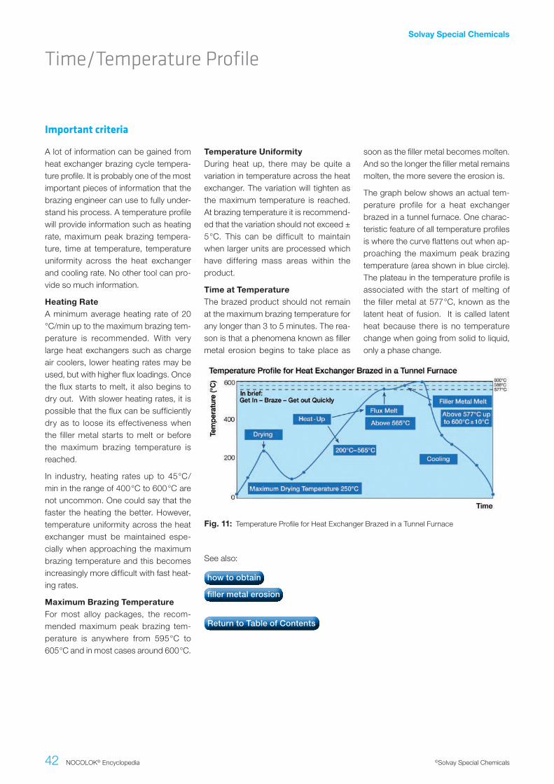
Solvay Special Chemicals
42 NOCOLOK® Encyclopedia ©Solvay Special Chemicals
A lot of information can be gained from heat exchanger brazing cycle tempera-ture profile. It is probably one of the most important pieces of information that the brazing engineer can use to fully under-stand his process. A temperature profile will provide information such as heating rate, maximum peak brazing tempera-ture, time at temperature, temperature uniformity across the heat exchanger and cooling rate. No other tool can pro-vide so much information.
Heating.RateA minimum average heating rate of 20 °C/min up to the maximum brazing tem-perature is recommended. With very large heat exchangers such as charge air coolers, lower heating rates may be used, but with higher flux loadings. Once the flux starts to melt, it also begins to dry out. With slower heating rates, it is possible that the flux can be sufficiently dry as to loose its effectiveness when the filler metal starts to melt or before the maximum brazing temperature is reached.
In industry, heating rates up to 45°C/min in the range of 400°C to 600°C are not uncommon. One could say that the faster the heating the better. However, temperature uniformity across the heat exchanger must be maintained espe-cially when approaching the maximum brazing temperature and this becomes increasingly more difficult with fast heat-ing rates.
Maximum.Brazing.TemperatureFor most alloy packages, the recom-mended maximum peak brazing tem-perature is anywhere from 595°C to 605°C and in most cases around 600°C.
Important criteria
Time/Temperature Profile
Fig..11: Temperature Profile for Heat Exchanger Brazed in a Tunnel Furnace
Temperature.UniformityDuring heat up, there may be quite a variation in temperature across the heat exchanger. The variation will tighten as the maximum temperature is reached. At brazing temperature it is recommend-ed that the variation should not exceed ± 5°C. This can be difficult to maintain when larger units are processed which have differing mass areas within the product.
Time.at.TemperatureThe brazed product should not remain at the maximum brazing temperature for any longer than 3 to 5 minutes. The rea-son is that a phenomena known as filler metal erosion begins to take place as
soon as the filler metal becomes molten. And so the longer the filler metal remains molten, the more severe the erosion is.
The graph below shows an actual tem-perature profile for a heat exchanger brazed in a tunnel furnace. One charac-teristic feature of all temperature profiles is where the curve flattens out when ap-proaching the maximum peak brazing temperature (area shown in blue circle). The plateau in the temperature profile is associated with the start of melting of the filler metal at 577°C, known as the latent heat of fusion. It is called latent heat because there is no temperature change when going from solid to liquid, only a phase change.
See also:
how to obtain
filler metal erosion
Return to Table of Contents

Solvay Special Chemicals
43 NOCOLOK® Encyclopedia ©Solvay Special Chemicals
During the commissioning of the fur-nace, a number of heat exchangers will be sacrificed. These units should be saved to become “dummy” units. Prior to the start of any production run, after a shutdown period or when a new prod-uct is to be run through the furnace, the dummies are run first to condition the atmosphere. In other words, the dum-my run is used to condition the furnace atmosphere so that steady state condi-tions can be reached prior to the actual braze run. This procedure may also be required when switching to products with a differing mass or configuration than the previous run.
Some heat exchanger manufacturers also run large pans of fresh flux along with the dummies to also condition the atmosphere with flux vapors.
See also:
Conditioning the furnace
Furnace Atmosphere
Return to Table of Contents

Solvay Special Chemicals
44 NOCOLOK® Encyclopedia ©Solvay Special Chemicals
HF Generation
Mechanisms and sources
Fig..12: Relationship between Dew Point and HF Formation
HF can potentially be formed during the flux brazing process. HF is very toxic, ir-ritating to the eyes, skin and respirato-ry tract and cause severe burns of the skin and eyes. The threshold limit value (TLV) for HF is a ceiling concentration of 3 ppm (2.3 mg/m3), a concentration that should not be exceeded during any part of the working shift.
Drying ovens can be electrically heat-ed or gas fired. In gas fired drying ov-ens, it is possible that any flux particles entrained in the moist air and passed through the high temperature flames may generate HF. The concern here is not so much with employee exposure, but that HF may be released into the at-mosphere.
Similarly, flux particles coming in contact with the hot flames in a flame brazing station may also generate HF. Suitable local exhaust systems must be in place to capture vapors and fumes that may contain HF.
It is known that one of the components of the flux, KAlF4, has a measurable va-por pressure and the rate of evaporation increases rapidly once the flux is molten. With regard to CAB brazing (furnace brazing) where traces of moisture are al-ways present even at below -40°C dew point, a number of compounds can be formed in the system K - Al - F - H - O. To our knowledge there has been no ac-ademic effort to create a thermodynamic model of this system. Thus, it is impossi-ble to predict which compounds will and will not exist, and in what temperature or humidity regimes. This is why more than one mechanism has been proposed for the generation of HF, but no unique re-action mechanism has been identified:
3KAlF4.+.3H2O...........Al2O3.+.K3AlF6.+.6HF
2KAlF4.+.3H2O..........2KF.+.Al2O3.+..6HF
While the evidence above points to gas phase reactions between flux fumes and water vapor for the generation of HF, Thompson and Goad1 proposed that AlF3 dissolved in the flux melt is subject to hydrolysis according to:
2AlF3.+.3H2O.........Al2O3.+.6HF
What is clear is that in all cases, HF is shown as a reaction product. As for the quantity, Field and Steward2 have indi-cated that the amount of HF formed is typically 20 ppm in the exhaust of a continuous tunnel furnace. Solvay’s own research work showed that even when flux on aluminum is heated in a bone-dry nitrogen atmosphere, a small quan-tity of HF is still generated3. A source of hydrogen must be made available for HF to be formed even under bone-dry con-ditions and this might include dehydra-tion of aluminium hydroxide, degassing
of furnace walls, leakage or other less obvious sources. The work showed that even under ideal conditions, it is virtually impossible to avoid some HF formation. The graph below shows the relationship between dew point and HF formation:
The amount of HF generated depends on several factors such as:
• Flux load going through the furnace – flux loading and component through put
• Temperature profile – heating rate and time at temperature
• Furnace atmosphere conditions such as nitrogen flow and dew point
The HF is exhausted together with the nitrogen stream and absorbed by the dry scrubber.
See also:
Return to Table of Contents
1 Thompson, W.T., Goad, D.W.G., Can. J. Chem., 1976, Vol. 54, p3342-33492 Steward N.I., Field D.J., SAE 870186, 19873 Lauzon, D.

Solvay Special Chemicals
45 NOCOLOK® Encyclopedia ©Solvay Special Chemicals
90°C.–.150°C.
• The moisture from the fluxing opera-tion is driven off. This does not in-clude the chemically bound water.
290°C.to.350°C
• Progressive release of chemically bound water in the flux (K2AlF5· H2O)
350°C.-.565°C
• KAlF4 begins to vaporize and react with moisture
• The more moisture there is to react, the more HF can be generated and the more the flux dries out as it is shifted away from its near eutectic composition.
565°C
• The flux starts to melt.
577°C.-.600°C
• The filler metal starts to melt.
• Filler metal flows and forms fillets at joints
Cooling
• The filler metal solidifies.
• The flux solidifies and remains on the surface as a thin tightly adherent residue.
The graph below shows a temperature profile for a brazed heat exchanger with the flux transformations. This provides an indication of approximately where in the brazing cycle these transformations occur:
Reactions
Brazing Reactions
Fig..13: Temperature Profile for a Brazed Heat Exchanger
See also:
HF generation
mechanisms and sources
Return to Table of Contents

Solvay Special Chemicals
46 NOCOLOK® Encyclopedia ©Solvay Special Chemicals
Flux Residues
Characteristics
General – After cooling, the flux resi-due remains on the surface of the heat exchanger as a very thin adherent film with a thickness of 1 to 2 microns. When properly brazed with recommended flux loadings, the flux residue is invisible to the naked eye.
Morphology. – At high magnification, the flux residue morphology has a crys-talline appearance and ranges from a needle-like structure to platelets. It is believed that the final morphology is de-pendent on factors such as cooling rate and oxygen content in the atmosphere during solidification.
Composition – The composition of the flux residue is the eutectic mixture of K3AlF6 and KAlF4.
Wettability - The wettability of the flux residue is good immediately after braz-ing, but degrades over time. The resi-due can be painted or conversion coat-ings can be applied.
Adhesion – Flux residue adhesion is excellent with less than 0.01% fall-off in thermal cycling tests at 10 g/m2 flux load. Detachment will occur with higher than recommended flux loads. As a rule of thumb, if the flux residue is visible, de-tachment is more likely to occur.
Brazed.sample.with.good.joint.formation
Poorly.brazed.sample.with.no.joint.formation
Post-braze.odor – Occasionally, there is a post-braze odor – a rotten egg smell – associated with flux residue. The odor is more of a nuisance for operators un-loading heat exchangers at the exit end of the furnace. The source of the odor is hydrogen sulfide (H2S). H2S is formed during the braze cycle in the cooling zone of the furnace and is generated from all traces of sulfur present in the system.
The conditions in the cooling zone are extremely reductive. The reaction of trace amounts of sulfur is connected to the re-oxidation of the aluminum surfaces af-ter joint formation and flux solidification:
This equation is neither trivial nor easy to explain. The driving force for this re-action is the energy of aluminum oxide formation. The oxidization leads to the reduction of other chemicals (e.g. - the sulfur of sulfate SO4
(2-) trace impurities,- or carbon in CO2). Humidity serves as a source for hydrogen.

Solvay Special Chemicals
47 NOCOLOK® Encyclopedia ©Solvay Special Chemicals
Flux Residues
Removal.– The flux residue is non-cor-rosive, non-hygroscopic and virtually in-soluble in aqueous media. The flux resi-due was never intended to be removed from brazed surfaces. There are no con-venient chemical removal methods and if it must be removed, it can only be do-ne by mechanical means such as wire brushing or grit blasting and only from robust joints (tube to fitting, tube to tube). Stainless steel wire brushes are recom-mended while brushes made from cop-per or brass should be avoided since the smallest of copper particles can cause severe erosion problems in subsequent brazing operations or can lead to gal-vanic corrosion if copper traces are left behind when the heat exchanger goes into service.
Flux residue has a slightly higher solubil-ity in strong alkalis and some acids. But in many cases the base materials (alumi-num or Stainless Steel) will be attacked (corroded) by these chemicals too.
A solution of hot boric acid (10 to 15%, 75 – 80°C) can be used to remove some of the flux residue from brazed assem-blies. Aluminum dissolution by boric acid is relatively moderate. The immer-sion time necessary to remove the bulk of residues varies from 10 to 30 minutes. But even then the flux residue removal will not be 100% successful.
Handling (preparation and usage) and discharging (waste disposal) of such chemical solutions can be problematic and expensive – due to their corrosive properties and the subsequently neces-sary waste water treatment. Consider-ations for health, safety and environment must be in accordance with the Safety Data Sheets.
Ultrasonic treatment may be effective in removing flux residues, provided that the parts to be cleaned fit into the ultra sonic dipping bath. A detergent (clean-ing agent) can be added to the solution to improve the cleaning activity. The use of Antarox BL 225 for ultrasonic clean-ing treatment is probably feasible. How-ever, when there are any other additional chemicals mixed with the Antarox-con-taining cleaning solution (particularly when adding acids or alkalis) their com-patibility with Antarox must be verified.
There are commercial solutions available for ultrasonic cleaning of Stainless Steel. More information on this subject is avail-able from suppliers for industrial clean-ing chemicals.
Summary:Flux residue from NOCOLOK® Flux can only be removed by mechanical means, i.e. using wire brushes or grit/ sand blasting. This is a very difficult and la-borious procedure - and a very dirty one (dust formation!). Local exhaust and ven-tilation is needed in the work area where the parts are cleaned. There is no suit-able solvent to take off the flux residue without corroding the base materials.
See also:
corrosion protection
influence of flux
residues
Return to Table of Contents

Solvay Special Chemicals
48 NOCOLOK® Encyclopedia ©Solvay Special Chemicals
Post Braze Flux Residue and Engine Coolants
For more than 30 years NOCOLOK® Flux has been used without any changes to the chemical composition in brazing op-erations (i.e. CAB/furnace, flame, and induction). However over the same time frame, several changes have taken place in terms of:
• Coolant chemistry – basic types: Inor- ganic Additive Technology (IAT), Or- ganic Additive Technology (OAT), Hy- brid Organic Additive Technology (HOAT), plus additives, plus pH buf-fers.
• Design of heat exchangers incorpo-rating more internal brazed surfaces with increased internal fluxing (e.g. on folded tubes, inserts, turbulators).
• More heat exchangers in the system loop and therefore more brazed sur-face area in contact with coolant.
• Reduced coolant volumes as a result of smaller and more efficient heat ex-changer designs.
• Coolant system materials of con-struction (new alloys, engineered polymers, mold release agents).
• Increased fluid flow velocities through heat exchanger compo-nents (erosion).
• Increased local engine temperatures due to bigger specific power (mani-folds, cylinder head, water cooled turbochargers, cylinder liner).
• Introduction of low temperature ra-diator without degassing systems.
Over the last several years, discussion of flux residue remaining on internal surfac-es of brazed aluminum heat exchangers has become an industry hot topic due to engine coolant stability issues that historically had not occurred prior to the coolant system changes noted above.
As a leading flux manufacturer, Solvay has been working with our customers and other industry suppliers to better understand the part that post brazed flux plays in this discussion.
Solvay Special Chemicals
49 NOCOLOK® Encyclopedia ©Solvay Special Chemicals
Post braze flux residues on internal wet-ted surfaces of brazed aluminum heat exchangers are slightly soluble in cur-rently used commercial coolants. Pa-rameters affecting the level of dissolved flux in coolants include:
• Flux residue quantity
• Residence time with the coolant
• Temperature
• Coolant formulation and additives
• pH stability of the coolant
• Water content of the coolant
• Number of brazed heat exchangers in the loop (total brazed internal sur-face area)
Experimental data indicates that some coolant additives react with dissolved flux, in particular with the aluminum component of flux:
• The coolant additives are designed to interact with aluminum species.
• It is important to note that aluminum oxides may be present from nor-mal detachment within aluminum heat exchangers, unassociated with flux residue. As an example, cool-ants used in vacuum brazed heat exchangers show presence of dis-solved aluminum in the system from this effect.
Slight flux dissolution occurs in water and coolants at neutral pH, but increas-es at acidic and alkaline pH levels. Many coolant formulations operate at alkaline pH, which increases the solubility of flux residue and of aluminum oxide.
Certain coolant additives can affect flux residue solubility. For example the addi-tion of borax (Na2[B4O5(OH)4]·8H2O) in-creases flux residue solubility, while the addition of a phosphate (KH2PO3) slight-ly decreases the solubility of potassium aluminum fluorides.
A recent result of our research is that Solvay determined a zero impact thresh-old limit of dissolved flux derived from joint work done with coolant, heat ex-changer, and automotive manufacturers. In a specific case for a silicate-based coolant, a threshold limit of a maximum of 0.5 g of dissolved flux per liter of cool-ant (50:50 mix ratio with water) could oc-cur with no noticeable depletion of the silicate reserve. Such threshold limits must be determined for each coolant formulation individually - considering also the exact coolant/water mixing ra-tios. As part of this study it is important to note that we found no evidence that fluorides cause depletion of silicates.
Key observations
Post Braze Flux Residue and Engine Coolants

Solvay Special Chemicals
50 NOCOLOK® Encyclopedia ©Solvay Special Chemicals
Determining Dissolved Flux Levels in Coolants
Several OEM automotive and truck pro-ducers are introducing specifications for internal heat exchanger cleanliness. In many cases potassium concentration measurements are used to verify how much flux residue dissolves in the cool-ant or water volume of a brazed heat exchanger. It must be emphasized that more flux residue dissolves in water than in coolant/water mixtures.
Based on the threshold level mentioned above (0.5 g/l) the corresponding potas-sium concentration would be 150 mg/l. Note that some coolants contain po-tassium species in the original coolant composition and this must be taken into account when evaluating the results.
Due to the chemical interactions of fluo-ride with aluminum oxide and dissolved aluminum we do not recommend using
fluoride concentration measurements as an indicator for dissolved flux resi-due. Furthermore, when using fluoride sensitive electrodes for analysis, it is challenging to distinguish between free fluoride ions and complex fluoride ions (e.g. AlF4-); thus, the results could be misleading.
Analyzing the exact level of aluminum in solution from dissolved flux residue is also problematic. Aluminum ions at alkaline pH will form aluminum hydrox-ide, which has low solubility and partially precipitates. This generally leads to Al concentrations lower than those calcu-lated on the basis of the potassium val-ues.
Post Braze Flux Residue and Engine Coolants
Solvay Special Chemicals
51 NOCOLOK® Encyclopedia ©Solvay Special Chemicals
OEM’s, coolant manufacturers, and heat exchanger manufacturers have deter-mined that other important factors be-sides flux residues play a part in coolant system stability. A partial list follows:
• The nature of the coolant composition and coolant additives
• Coolant system operating design that avoids overheating and hot-spots
• Minimization of coolant exposure to air
• Avoiding exposure of coolants to exhaust gases
• Usage of inert coolant system materi- als of construction
• Prevention of oxidized iron/steel com- ponents prior to coolant fill
Other factors
Summary
Coolant stability is critical to ensure proper engine heat management and to achieve the expected lifetime of modern heat exchanger systems. The heat ex-changer design, operating parameters, materials of construction, and coolants all must be evaluated as they each im-pact system stability. It has been shown that interactions can occur between the dissolved flux component and certain coolant additives. Understanding which additives may interact with dissolved flux
is important. Of course, to reduce the amount of dissolved flux, the minimiza-tion of flux load becomes an important goal in the heat exchanger manufactur-ing process.
See also:
Post Braze Flux Residue and Engine Coolants
corrosion protection
influence of flux residues
Return to Table of Contents

Solvay Special Chemicals
52 NOCOLOK® Encyclopedia ©Solvay Special Chemicals
Effluent treatment
Dry Scrubber
It is known that HF is produced inside the brazing furnace by the reaction of KAlF4 with moisture, even at extremely low dew points. To prevent the release of HF into the atmosphere, it is necessary to install a dry scrubber.
The scrubber consists of large enclosure containing 2 or more beds of 5– 8 mm activated alumina pellets. The first bed acts as a dust adsorption layer for the KAlF4 effluent and any other dust en-trained in the effluent stream. The sec-ond bed is the fluoride adsorption layer where HF reacts with the activated alu-mina according to the following equa-tion:
Al2O3.+.6HF........2AlF3.+.3H2O
The scrubbing efficiency is up to 90%, that is the dry scrubber retains 90% of the HF so that only a minute amount is
released into the atmosphere. Measure-ments have shown that the HF concen-tration in the exhaust of a typical tunnel furnace is about 20 ppm. With a 90% scrubbing efficiency, only 2 ppm HF is released into the atmosphere.
Below is a schematic of a typical scrub-ber for a CAB brazing furnace:
See also:
HF generation
mechnaisms and sources
Return to Table of Contents
Fig..14: Typical Scrubber for CAB Brazing Furnace

Solvay Special Chemicals
53 NOCOLOK® Encyclopedia ©Solvay Special Chemicals
Flame brazing with NOCOLOK® Flux lends itself well to joining components with simple configurations such as tube-to-tube, tube-to-fitting and joints with large thermal mass differences. Since much faster heat-up rates are possible than in furnace brazing, flame brazing is versatile and can braze Mg containing alloys which would be difficult or impos-sible in furnace brazing.
A range of equipment is available for flame brazing, ranging from simple hand-held torches to fully automated carousels complete with optical py-
rometer temperature measurement de-vices. Filler metal is available in a variety of shapes and forms including pastes, wire, preforms, shim, flux cored wire and flux coated wire.
Unlike furnace brazing, flame brazing typically leaves behind a visible flux resi-due.
See also:
General Features
Flame Brazing
hardware and consumables
automation
Return to Table of Contents

Solvay Special Chemicals
54 NOCOLOK® Encyclopedia ©Solvay Special Chemicals
Hardware and consumables
Flame Brazing
Torch – It is critical that the joint area is brought up to temperature uniformly. For this reason, a dual-headed torch is recommended for manual flame brazing and multiple torches may be used in au-tomated systems.
Torch.tip – A multi-orifice tip generates a broad flame which enhances compo-nent temperature uniformity during heat up. Pin-point flames should be avoided as burn-through can easily occur.
Gas – Most commercial gas mixtures are acceptable for flame brazing alumi-num:
• Oxygen-propane
• Oxygen-methane
• Oxygen-natural gas
• Oxyacetylene (produces hottest flame and increases likelihood of burn- through
Filler.metal – The filler metal alloy most commonly used for flame brazing is AA4047 which contains 11 to 13% Si. AA4047 has the lowest melting range and the highest fluidity of all commercial filler metal alloys – ideal properties for flame brazing. The filler metal is avail-able in a variety of shapes and forms including wire, rings, powder and foil. When used as a powder, it is usually mixed with a flux and a carrier to form a paste. Filler metal wire is also available commercially either cored or coated with flux, precluding the application of flux.
Braze.paste – Commercially available braze pastes consist of the flux, pow-dered filler metal and a binder/carrier to keep the ingredients in uniform suspen-sion. This paste is all-inclusive; there is no need to supply flux or filler metal to the joint separately. Braze pastes can also be applied with automatic dispens-ers, with syringes or by brush applica-tion.
Flux. paste – This is similar to braze pastes except that there is no powdered filler metal, meaning that flux paste re-quires filler metal in one form or another to be added to the joint separately. The advantage of suing a flux paste is that the end user does not have to prepare his own paste.
In.house.paste.preparation – This is an inexpensive option whereby the user prepares his own pastes by mixing flux and water and/or alcohol (isopropyl al-cohol). These type of paste preparation is not easily dispensable automatically and is usually applied with a brush.
See also:
General Features
Automation
Return to Table of Contents

Solvay Special Chemicals
55 NOCOLOK® Encyclopedia ©Solvay Special Chemicals
Shuttle.systems – The shuttle system consists of a framework on which one or two components requiring brazing are mounted where the motor driven framework laterally shuttles the braze joints between one or two braze stations each equipped with opposing flames. The shuttle is configured such that one or two new components requiring braz-ing can be installed on the return of the shuttle to its original position and the brazed units unloaded.
Carousels – Flame brazing carousels are at the upper level of automation. The carousels move assembled com-ponents to be brazed continuously from flame station to flame station arranged in a circular pattern (hence the name carousel). Usually, each flame station consists of two stationary and oppos-ing torches between which the joint to
be brazed is indexed. As the component moves from station to station, the joint temperature gets progressively hotter. The number of stations depends on the joint configuration and weight. The joint is thus uniformly heated to brazing tem-perature. The last station where brazing takes place may be equipped with an optical pyrometer to monitor braze joint temperature. After brazing, the joint may be cooled by air or water spray. Other options include automatic application of filler metal and/or dispensing of flux (filler metal ring, flux/braze paste).
See also:
Automation
Flame Brazing
Hardware and consumables
General Features
Return to Table of Contents
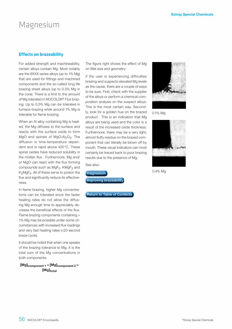
Solvay Special Chemicals
56 NOCOLOK® Encyclopedia ©Solvay Special Chemicals
Effects on brazeability
For added strength and machineability, certain alloys contain Mg. Most notably are the 6XXX series alloys (up to 1% Mg) that are used for fittings and machined components and the so-called long life brazing sheet alloys (up to 0.3% Mg in the core). There is a limit to the amount of Mg tolerated in NOCOLOK® Flux braz-ing. Up to 0.5% Mg can be tolerated in furnace brazing while around 1% Mg is tolerable for flame brazing.
When an Al alloy containing Mg is heat-ed, the Mg diffuses to the surface and reacts with the surface oxide to form MgO and spinels of MgO:Al2O3. The diffusion is time-temperature depen-dent and is rapid above 425°C. These spinel oxides have reduced solubility in the molten flux. Furthermore, Mg and/or MgO can react with the flux forming compounds such as MgF2, KMgF3 and K2MgF4. All of these serve to poison the flux and significantly reduce its effective-ness.
In flame brazing, higher Mg concentra-tions can be tolerated since the faster heating rates do not allow the diffus-ing Mg enough time to appreciably de-crease the beneficial effects of the flux. Flame brazing components containing > 1% Mg may be possible under some cir-cumstances with increased flux loadings and very fast heating rates (<20 second braze cycle).
It should be noted that when one speaks of the brazing tolerance to Mg, it is the total sum of the Mg concentrations in both components:
[Mg]component.1.+.[Mg]component.2.=..[Mg]total
The figure right shows the effect of Mg on fillet size and geometry:
If the user is experiencing difficulties brazing and suspects elevated Mg levels as the cause, there are a couple of ways to be sure. First, check with the supplier of the alloys or perform a chemical com-position analysis on the suspect alloys. This is the most certain way. Second-ly, look for a golden hue on the brazed product. This is an indication that Mg alloys are being used and the color is a result of the increased oxide thickness. Furthermore, there may be a very light, almost fluffy residue on the brazed com-ponent that can literally be blown off by mouth. These visual indicators can most certainly be traced back to poor brazing results due to the presence of Mg.
See also:
0.1% Mg
0.4% Mg
Magnesium
magnesium
improving brazeability
Return to Table of Contents

Solvay Special Chemicals
57 NOCOLOK® Encyclopedia ©Solvay Special Chemicals
Magnesium
There are a few ways in which the braze-ability of Mg containing alloys can be im-proved:
I. Increasing the flux loading. A sub-stantial improvement is gained when increasing the flux loading up to 10 g/m2 or more in furnace brazing. In cases where there is just one com-ponent containing Mg such as in a fitting, extra flux can be brushed around the area of the joint.
II. Increasing the heating rate. Slow heating rates allow more Mg to dif-fuse to the surface thereby hindering
brazeability. For furnace brazing Mg containing alloys, the fastest possi-ble heating rates achievable without sacrificing temperature uniformity will increase the tolerance to Mg.
III. Combining increased flux loadings and faster heating rates.
IV. Maintaining proper gap tolerances and joint designs.
V. Increasing the nitrogen flow rate to minimize furnace atmosphere con-taminants that also compete to re-duce brazeability.
Improving brazeability
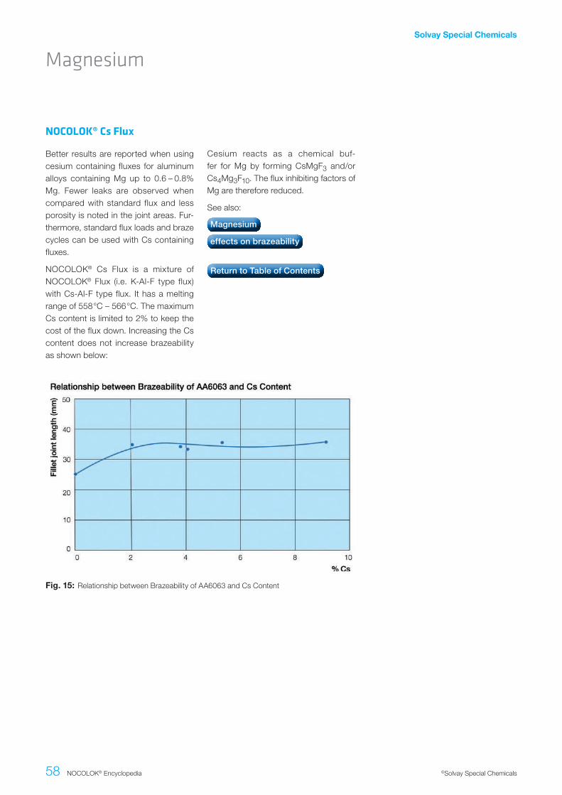
Solvay Special Chemicals
58 NOCOLOK® Encyclopedia ©Solvay Special Chemicals
NOCOLOK® Cs Flux
Better results are reported when using cesium containing fluxes for aluminum alloys containing Mg up to 0.6 – 0.8% Mg. Fewer leaks are observed when compared with standard flux and less porosity is noted in the joint areas. Fur-thermore, standard flux loads and braze cycles can be used with Cs containing fluxes.
NOCOLOK® Cs Flux is a mixture of NOCOLOK® Flux (i.e. K-Al-F type flux) with Cs-Al-F type flux. It has a melting range of 558°C – 566°C. The maximum Cs content is limited to 2% to keep the cost of the flux down. Increasing the Cs content does not increase brazeability as shown below:
Cesium reacts as a chemical buf-fer for Mg by forming CsMgF3 and/or Cs4Mg3F10. The flux inhibiting factors of Mg are therefore reduced.
See also:
Fig..15: Relationship between Brazeability of AA6063 and Cs Content
Magnesium
Magnesium
effects on brazeability
Return to Table of Contents

Solvay Special Chemicals
59 NOCOLOK® Encyclopedia ©Solvay Special Chemicals
Cross-Section.of.As-Extruded.and.Overheated.Machineable.Alloys
Mg containing alloys have lower melt-ing points than those alloys containing very low or no Mg. In flame brazing ap-plications, machineable alloys such as AA6061 and AA6063 are often used and contain 1% Mg and 0.5% Mg, re-spectively. Both of these alloys have a solidus of 616°C. This means that these alloys, when overheated are prone to in-cipient grain boundary melting. The ef-fect of overheating manifests itself as degradation of the microstructure and a roughening of the skin commonly known
as “orange peel”. This effect is often worse in the outer skin of flame-brazed components containing Mg. The outer surface sees a higher temperature than deeper within the component. Metallur-gical degradation of this type can cause problems with the longevity and suitabili-ty of machined surfaces such as threads in fittings.
See also:
Degradation of microstructure
Magnesium
Return to Table of Contents
As extruded
Heated to 630°C

Solvay Special Chemicals
60 NOCOLOK® Encyclopedia ©Solvay Special Chemicals
Using the angle on coupon test, a re-cent study showed that there was only a small drop in brazeability when the ox-ide thickness was increased from 40 to 220 Angstroms at 5 g/m2 flux loading. There was however an appreciable drop in clad fluidity as the oxide thickness in-creased from 40 to 100 Angstroms at 2 g/m2 flux. A reduction in brazeability was even noted as the oxide thickness was increased from 40 to 60 Angstroms.
This is testament to the fact that proper flux loadings should be maintained since low flux loadings appear to be quite sen-
sitive to even small changes in oxide thickness.
See also:
Reference
Gray, A., Flemming A.J.E., Evans J.M., VTMS 4 conference proceedings, Lon-don, 1999
Effect on brazing
Oxide Film Thickness
Return to Table of Contents

Solvay Special Chemicals
61 NOCOLOK® Encyclopedia ©Solvay Special Chemicals
Brazing Sheet
Description and Microstructure
Brazing sheet is used extensively in the production of automotive heat exchang-ers such as radiators, heater cores, con-densers and evaporators. Brazing sheet is produced by bonding a liner of an Al-Si alloy on one or both sides of a core ingot via hot rolling. The liner and core dimensions are chosen to produce the desired thickness of the Al-Si alloy when the clad sheet is rolled to final gauge. The core provides structural integrity while the cladding melts and flows dur-ing the brazing process to provide, on cooling, a strong metallurgical bond be-tween the components.
Below is an actual metallographic cross-section of as-rolled 2-sided clad brazing sheet showing the clad bonded to the core.
To someone not skilled in the art, one sees only a number of black dots on a white background. These black dots are actually constituents and interme-tallic phases which make up that par-ticular alloy. In this case, the core al-loy is AA3003 or Al-1.25% Mn. The Mn addition provides certain mechanical properties to Al. During processing, the constituents not soluble in Al coalesce and precipitate out of solution (the black dots) to give, in this case, intermetallic phases such as MnAl6, αAl(FeMn)Si or Mn-Al dispersoids.

Solvay Special Chemicals
62 NOCOLOK® Encyclopedia ©Solvay Special Chemicals
During brazing the clad layer melts and flows to all joints to be formed. Upon cooling, or more correctly upon solidifi-cation, the microstructure of the original clad looks very different. The following figure below shows what a typical fin-to-tube joint looks like after brazing
The Al-Si alloy microstructure is shown after recrystallization and solidification.
The Si is now present as a plate-like structure. Another characteristic feature is the presence of dendritic cells sur-rounded by the Al-Si eutectic network. What is also noteworthy is that the filler metal formed a metallurgical bond be-tween the fin and the tube, i.e., there is a continuous metal path between the fin and the tube.
See also:
Microstructure after brazing
Brazing Sheet
brazing sheet
core alloys cladding alloys
aluminum association alloy designations
Return to Table of Contents
Post brazed filler alloy residue left on
Al-Si eutecitic
Intermetallic compound
Shrinkage Porosity
AI grains – aluminium

Solvay Special Chemicals
63 NOCOLOK® Encyclopedia ©Solvay Special Chemicals
Aluminum Alloys
Aluminum alloys are classified according to their alloying elements. The Aluminum Association designations are listed be-low:
• 1XXX 99.00% minimum Al
• 2XXX Copper
• 3XXX Manganese
• 4XXX Silicon
• 5XXX Magnesium
• 6XXX Magnesium and silicon
• 7XXX Zinc
• 8XXX Other elements
• 9XXX Unused series
As a valuable reference, a complete re-cord of all Aluminum Association desig-nated alloys is available:
International.Alloy.Designations.and.Chemical.Composition.Limits.forWrought.Aluminum.and.Wrought.Aluminum.Alloys
This document is available by contact-ing:
The Aluminum Association 900 19th Street, N.W., Washington, D.C., 20006
See also:
Brazing Sheet
brazing sheet what is brazing sheet?
core alloys cladding alloys
Return to Table of Contents

Solvay Special Chemicals
64 NOCOLOK® Encyclopedia ©Solvay Special Chemicals
The core alloys in common use for heat exchanger manufacturing include, but are not limited to: AA3003, AA1100, AA1145, AA1070, AA3005, AA3105, AA6951, AA1050, AA1435, AA3102, AA6063.
Aluminum producers are now offering so-called “Long Life Alloys”. These are modified AA3XXX series alloys, offering superior strength and corrosion resis-tance. These alloys have not been des-ignated by the Aluminum Association
and are known only by their manufac-turers’ designations. Some examples of long life alloys are: X800, X900, HE45, K315, K319, MD267 etc.
See also:
aluminum association alloy designa-tions, what is brazing sheet.
Core alloys
Brazing Sheet
corrosion protection
long life alloys
cladding alloys

Solvay Special Chemicals
65 NOCOLOK® Encyclopedia ©Solvay Special Chemicals
Cladding Alloys
The cladding alloy (filler metal) is the thin layer of the Al-Si alloy that is bonded to the core alloy. This thin cladding alloy, usually making up 5% to 10% of the to-tal thickness of the brazing sheet, melts and flows during the brazing process, to provide upon cooling a metallic bond between the components.
The addition of Si lowers the melting point of Al. The eutectic composition, that is the amount of Si required to pro-duce the lowest melting point is 12.6% Si. The melting point at this composition is 577°C. At lower Si levels, the solidus or the point at which melting begins is also 577°C. However melting occurs over a range and the temperature above which the filler metal is completely molten is called the liquidus. In between the soli-dus and liquidus, the filler metal is par-tially molten, existing as both solid and liquid. The difference between solidus and liquidus forms the basis for various filler metal alloys. Commercial filler met-als may contain form 6.8% to 13% Si.
AA4343:..6.8.to.8.2%.Si. ..Melting.point.range:..577.to.605°CThis alloy has the lowest Si content and consequently the longest freezing range. It is the least fluid of the filler alloys and the least aggressive at dissolving the core alloy.
AA4045:..9.0.to.11.0%.Si. .Melting.point.range:..577.to.590°CThis is the most common of the filler al-loys. Its properties are between AA4343 and AA4047.
AA4047:..11.0.to.13.0%.Si.Melting.point.range:..577.to.580°CThis alloy has the highest fluidity be-cause of its extremely narrow melting range (eutectic composition). AA4047 flows rapidly on melting and is the most aggressive at dissolving the core alloy. Because of these properties, it is not used as a cladding alloy (although it may), but more in flame brazing applica-tions where these properties are in fact desirable.
See also:
Brazing Sheet
brazing sheet
core alloys
what is brazing sheet?
aluminum association alloy designation
Return to Table of Contents

Solvay Special Chemicals
66 NOCOLOK® Encyclopedia ©Solvay Special Chemicals
Folded tubes (or B-type tubes) for radia-tors have been developed several years ago. There are slightly different designs patented by most of the heat exchanger manufacturers.
Below illustrations show three different B tube designs:
The folded tubes are produced from brazing sheet coils by a multi-step roll forming process – bringing the sheet gradually into a “B” shape. B-tubes have certain advantages – particularly regard-ing strength. The folded ends of the tube sheet are brazed inside the tube, which creates a very robust bridge between the walls. This results in higher burst pressure resistance.
The B tube roll forming process replaces the tube seam welding procedure. Stan-dard flat radiator tubes are seam weld-ed on one side – while folded tubes are joined during brazing. It is a general ob-servation that folded tubes (“B-tubes”) are more difficult to braze (when com-pared with seam welded tubes).
Some of the problems are related to flux coverage. Other difficulties are related to erosion effects due to the fact that there is more filler metal available from folded tubes than from welded tubes. One common feature of all folded tubes designs is the presence of a triangular gap or “delta” between the flat exteri-or portion of the tube wall surface and the fin convolution. This delta is creat-ed by the presence of the folds in the tube. This is a common failure site at the tube to header joint because there is not enough filler metal at the joint to allow for proper fillet formation.
In order to avoid troublesome inner tube fluxing and to minimize the level of flux residue in the cooling loop it has be-come more and more common to flux
the tube folds (the so called leg) at the folding machine using a needle like dis-penser which places a thin bead of flux paste along where the tube leg touches the tube inner surface in the subsequent folding operation. A specially formulated flux paste is required for such operation. Solvay offers for this purpose a product called Ultra Flux Paste.
Another common feature with folded tube designs is that the fin-to-tube-joints are consistently larger on the folded tube side than on the non-folded side of the tube. This is attributed to the path cre-ated by the fold in the tube which allows the filler metal to flow from the header, up the tube and from the tube fold pan-els up into the fin to tube joint.
The dominant phenomenon present in brazing is capillarity, i.e. the force which draws the filler metal into the joints. A heat exchanger core may be considered as a complex matrix of capillary sites. Now, in a non-folded tube design, all the joints are considered separate and au-tonomous, that is none of the joints are connected. For the most part then, filler metal is drawn into the fin to tube and tube to header joints from the immediate area surrounding the joint.
Brazing Issues
Folded Radiator Tubes (B-Tubes)
Fig..16: B-Tubes

Solvay Special Chemicals
67 NOCOLOK® Encyclopedia ©Solvay Special Chemicals
When a folded tube is added, many of the previously separated joints become connected and inter-dependent. The fin to tube joints on the side of the tube fold are now in direct contact with the seam along the fold of the tube, which is also in contact with the tube to header joint at the header slot. Now, the heat exchanger has an extended zone to draw filler met-al from, as the available clad for the fin to tube joint now extends throughout the entire length of the tube seam and even includes the header. During brazing, the center of the core will heat up faster (lighter weight compared to the heavier thermal mass of the headers and side supports) and creates a temperature gradient. The filler metal from the header is able to travel down the seam through-out the length of the seam, depleting the area around the tube to header joint of valuable filler metal. The result is smaller tube to header joints with a greater risk of failure and large tube to fin joints on the folded side of the tube.
One way to reduce the flow of filler metal along the seam resulting in saturation of the tube to fin joints is by putting Mg in the fin. This goes back to the principle of competing joints, where the joint with more Mg will draw less filler metal. By adding a small percentage of Mg in the fin yet keeping it brazeable, the wet-tability of the fin to tube joint is slightly reduced. The fin-to-tube-joints neither draw up all of the available clad from the headers nor from the tube seams. The clad no longer runs up the tube. Reduced wettability forces the clad to stay in the tube seam and in the tube to header joints.
If problems are observed with exces-sively large tube to fin joints on the fold-ed tube side and/or if the tube to header joints are small and commonly fail due to a lack of filler metal, it may be consid-ered to use fins with more Mg – to take advantage of the features mentioned above.
See also:
Folded Radiator Tubes (B-Tubes)
Return to Table of Contents
Solvay Special Chemicals
68 NOCOLOK® Encyclopedia ©Solvay Special Chemicals
Aluminum in high purity form is very soft and ductile and has little use from a me-chanical standpoint. Any commercial use requires greater strength and me-chanical properties than what pure alu-minum affords. Higher strength proper-ties are achieved by the addition of other elements (singly or in combination). Fur-ther strengthening is possible by means which classify the alloys as heat treat-able or non heat treatable.
The Aluminum Association has adopt-ed a basic temper designation system
which is based on the sequences of ba-sic treatments required to produce vari-ous tempers. The temper designation usually follows the alloy designation, for example AA1100-H18. The basic temper designation consists of letters. Subdivi-sions of tempers are indicated by one or more digits following the letter. These numbers indicate a specific sequence of basic treatments.
In this group of alloys, the initial strength of the alloy depends on the hardening effects of elements such as manganese, silicon, iron and magnesium. Non-heat-treatable alloys are work-hardenable.
Higher strength is achievable by various degrees of cold work or strain harden-ing. The 1XXX, 3XXX, 4XXX and 5XXX series are non-heat-treatable alloys.
Tempers
Designations
Non-heat-treatable alloys
Aluminum Metallurgy
F = as fabricated
• Applies to products which acquire some temper from shaping, but no attempt is made to control the amount of cold work or thermal treatment.
O = Annealed
• Annealing is any heat treatment at elevated temperature which has as its sole purpose a softening effect. Softening occurs simultaneously with a reduction in strength and an increase in ductility.
• O-temper applies to products which are annealed to obtain the lowest possible strength temper.
H = Strain Hardened
• Applies to products that have their strength increased by strain harden-
ing with or without supplementary thermal treatment to produce partial softening. The H designation is al-ways followed by two or more dig-its. The first digit indicates the spe-cific combination of basic operations while the second digit indicates the degree of strain hardening.
H1 = Strain hardening only
• H12 - ¼ hard
• H14 - ½ hard
• H16 - ¾ hard
H2 = Strain hardening + partial anneal
• H22 - ¼ hard
• H24 - ½ hard
• H26 - ¾ hard

Solvay Special Chemicals
69 NOCOLOK® Encyclopedia ©Solvay Special Chemicals
Aluminum Metallurgy
Aluminum alloys can be strengthened by a process called precipitation hard-ening. In this treatment, the alloy is first heated to a temperature that puts the soluble alloying elements into solid solu-tion. After this, the alloy is quenched to a low temperature to keep these elements in supersaturated solid solution. The second step is aging during which the precipitate forms. If precipitation, which
hardens the alloy, takes place at room temperature the alloy is said to be natu-rally aged. If the alloy must be heated for precipitation to occur, the alloy is said to be artificially aged. Alloys that can be strengthened by precipitation hardening are known as heat treatable alloys. The 2XXX, 6XXX and 7XXX series are heat treatable alloys.
Heat treatable alloys
Designations
T tempers
• Applies to products which are ther-mally treated, with or without sup-plementary strain hardening. The T temper is always followed by one or more digits and each number indi-cates one specific sequence of basic treatments.
T1 = heat treated and naturally aged
T2 = heat treated, cold worked and natu- rally aged
T3 = solution heat treated, cold worked and naturally aged
T4 = solution heat treated and naturally aged
T5 = heat treated and artificially aged
T6 = solution heat treated and artificially aged
T8 = solution heat treated, cold worked then artificially aged
See also:
Return to Table of Contents

Solvay Special Chemicals
70 NOCOLOK® Encyclopedia ©Solvay Special Chemicals
During the brazing cycle, Si from the cladding alloy diffuses into the core. At a given temperature, when the concentra-tion of Si in the matrix alloy exceeds the solidus line of the Al/Si phase diagram, the solid material of the matrix starts melting. This process in the brazing in-dustry is known as diffusion and may be defined as follows:
Diffusion = The dissolution of the solid matrix by the static contact of the liquid filler metal.
If for any reason the liquid part of the matrix flows away, it will leave a groove or gutter on the solid surface. A gutter can also be created by the continuous flow of filler metal over the solid surface. This phenomena is known as erosion:
Erosion = a gutter, groove or depletion of the solid matrix caused by a liquid portion of the former solid matrix flow-ing away, or by filler metal alloy flowing over a surface which rapidly dissolves the substrate.
Erosion is a very dangerous phenom-enon since it results in a reduction in thickness of the core material, thus giv-ing rise to accelerated fatigue or prema-ture corrosion failure. One must realize that at higher temperatures penetration of Si into the matrix will always occur due to high concentration gradient between the filler alloy and the matrix. Therefore a certain amount of diffusion is hardly avoidable and the industry seems to ac-
cept diffusion depths of up to 10% to 20% of the original thickness of the base metal. However the permissible limit for erosion on the other hand is much lower and usually does not exceed 5%.
The extent of diffusion and erosion is in-creased by higher Si levels in the clad-ding alloy, longer than recommended braze cycles, excessive peak brazing temperatures, excessive thickness of the cladding alloy and a design which allows pooling of the braze metal to oc-cur. In some instances, the extent of filler metal erosion is so severe that the entire thickness of the base metal (tube or fin) is consumed resulting in catastrophic failures.
The most common factors leading to ex-cessive erosion are not design related, but process related. Brazing beyond the recommended maximum peak tempera-ture (> 605°C) and/or dwelling at braz-ing temperature (> about 3 to 5 minutes) are the 2 leading causes of erosion and these can both be controlled at the pro-cess level.
See also:
Filler Metal: Diffusion and Erosion
Filler Metal
Diffusion and Erosion
what a look for Examples
Return to Table of Contents

Solvay Special Chemicals
71 NOCOLOK® Encyclopedia ©Solvay Special Chemicals
What to look for?
Heat exchangers suffering from exces-sive diffusion/erosion may not be im-mediately caught by the conventional quality control tests (leak tests, burst pressure tests etc.). Only a metallo-graphic examination could determine how much erosion actually occurred and this is not performed on all heat ex-changers.
Below are some examples of metallo-graphic cross-sections showing the ef-fects of temperature on diffusion. Note that as the temperature increases, the tubes and fins become increasingly more affected by diffusion.
The fins closest to the tube to header joints should be examined. If the fluidity of the filler metal at the tube to header joint is increased (excessive heat), some of the filler metal may be released and flow to the nearest tube to fin joints. This excess filler metal may then be drawn in between the fins by capillary action. Vi-sually, it would appear that the fins are clogged with metal and in extreme cas-es some of the fins may be disintegrat-ed. The industry commonly refers to this disintegration as “fin burning”, but this is a misnomer as the fins are not burnt at
all, but merely significantly eroded to the point of complete disintegration.
In addition look for signs that some of the fins may have brazed together. On the tubes leading away from the tube to header joints, look for small channels that may have been dug out by the flow-ing filler metal.
If any of these signs are apparent, a fur-ther metallographic examination is rec-ommended to assess the degree of dif-fusion and erosion.
595°C for 5 minutes 610°C for 2 minutes 625°C for 2 minutes
Filler Metal: Diffusion and Erosion

Solvay Special Chemicals
72 NOCOLOK® Encyclopedia ©Solvay Special Chemicals
A common example of the gravity of ero-sion is in the case of parallel flow con-densers. Due to the nature of the extru-sion process, there are longitudinal die lines on the surface of the tube. Filler metal from the header can flow along these die lines between the header and the first fin and cause significant to cata-strophic erosion (through the thickness of the tube).
It is not completely understood what ac-tually initiates the filler metal flow along the die lines, but the erosion mechanism and the leak formation is clearly related to it. The leaks can be found in a ran-dom pattern on some tubes, but it is impossible to predict on exactly which tubes this will happen.
Erosion can also occur on radiators with folded tubes. The fold on the sur-face of the tube is an area where capil-lary forces can develop during brazing. Filler metal from the header flows along these surfaces resulting in erosion. Ero-sion can also be seen along the seam of seam-welded radiator tubes. Again it is not clear what initiates the flow of filler metal along the weld seam, but the results can be catastrophic as shown in the photo at left below and the photomi-crograph at right.
See also:
Examples
Filler Metal: Diffusion and Erosion
what to look for
Return to Table of Contents

Solvay Special Chemicals
73 NOCOLOK® Encyclopedia ©Solvay Special Chemicals
Requirements
Joints to be metallurgically bonded must have intimate contact at some point along the joint. Adequate filler metal, but not an excessive amount, must be avail-able to fill the joint. A common phrase to emphasize this point is that “filler metal can run, but it cannot jump”. This means that is necessary to have intimate con-tact between the 2 components to be joined and the filler metal at some point along the joint. This contact point is what initiates the capillary flow of the filler metal.
A gap between the 2 components to be joined is necessary to (1) allow the molten flux to be drawn into and clean and dissolve the oxides and (2) allow the filler metal to be drawn in freely and evenly. The size of the gap determines
the strength of the capillary pull. For NOCOLOK® Flux brazing, gap clear-ances of 0.10 mm to 0.15 mm are rec-ommended for non-clad components (when the filler metal is fed externally – via filler metal wire). For clad compo-nents such as in a tube to header joint where the tube is clad, the clearance is provided by the thickness of the clad-ding layer and so intimate contact is rec-ommended.
Larger gap clearances reduce capillary action while smaller gaps may restrict filler metal flow causing discontinuities in the joint. Friction fits must be avoided with non-clad components.
See also:
Gap Clearances
Return to Table of Contents

Solvay Special Chemicals
74 NOCOLOK® Encyclopedia ©Solvay Special Chemicals
When a heat exchanger is assembled using clad components, there will be a reduction in the overall dimensions of the heat exchanger after brazing. These di-mensional changes result when the clad layer on the components melt and flow so that the reduction in dimension is al-
most equivalent to the cumulative thick-ness of cladding. The greater the num-ber of tubes and fins, the greater the dimensional change will be.
See also:
The coefficient of thermal expansion is greater for aluminum than for stainless steel. This must be considered when designing fixtures for heat exchangers. Otherwise the fixture can distort the heat exchanger during the heat cycle. A sign
that this has occurred is when the fins appear crushed and/or the tubes bow inwards.
See also:
Dimensional changes during brazing
Expansion of fixtures
Product Fit up
Return to Table of Contents
Return to Table of Contents

Solvay Special Chemicals
75 NOCOLOK® Encyclopedia ©Solvay Special Chemicals
Hourglassing
If a waterside tube to header joint is ex-amined and the 2 sides of the tube ap-pear to be pushed inwards resulting in an hourglass shape, this is a sign of ei-ther poor fit up or by differential expan-sion of the tube and header (the lighter tube heats up faster than the heavier header) or poor fit up even before braz-ing. In either instance, pressure is exert-ed on the noses of the tube and the tube sides are forced inward resulting in the hourglass shape.
Poor fit up in this case would mean that the header slots are not sized properly for the dimensions of the tube. Even if hourglassing does not occur, improper fit up at the tube to header joint often results in failures (leakers).
See also:
Product Fit up
Return to Table of Contents
Fig..17: Hour Glassing

Solvay Special Chemicals
76 NOCOLOK® Encyclopedia ©Solvay Special Chemicals
Repair of leakers is possible using either flame or furnace brazing techniques. The area to be repaired should be wire brushed to remove excess flux residue, especially if the alloys involved contain Mg. This is to remove the formation of MgO or MgF2 that may have formed at the joint and can interfere with the repair. Only one repair should be attempted. This is to prevent further Si diffusion and erosion that may severely compromise the mechanical and corrosion proper-ties. If the repair is unsuccessful, the unit should be scrapped or saved as a dummy for production start up.
Most repair work is carried out by ap-plying a commercially available “braze paste” consisting of filler metal in pow-dered form, flux and a suitable binder. The Paste is dispensed in the leak ar-ea and re-brazed either by running the component through the furnace or with a flame by carefully heating the area until the flux and filler metal melt and heal the leak. Performing this operation with a torch is very difficult as it is unavoidable to heat up the surrounding area where burn-through is very likely.
See also:
Braze Repair
Return to Table of Contents

Solvay Special Chemicals
77 NOCOLOK® Encyclopedia ©Solvay Special Chemicals
It is generally accepted that the pres-ence of flux residues on a heat exchang-er enhances its corrosion resistance. The references below attest to this fact. However, it has always been difficult to quantify the level of corrosion resistance enhancement. In corrosion testing of flat panels or coupons coated with flux residue, there is no doubt that there is a beneficial effect. With heat exchang-ers on the other hand, the general trend shows a longer corrosion life, but factors such as uniformity of flux residue cover-age and variations in flux loadings some-times confuse the corrosion test data.
References
Nakazawa, T., Tanabe, K., Ushikubo, K., and Hiraga, M., Performance Evaluation of Serpentine Evaporator for Automo-tive Air-conditioning System, SAE paper 840384, Warrendale, PA Claydon, D., Sugihara, A., Brazing Aluminum Auto-motive Heat Exchanger Assemblies Us-ing a Non-Corrosive Flux, SAE paper 830021, Warrendale PA
Cooke, W., Bowman, A., Tunnel Furnace Brazing of Aluminum Using a Non-Cor-rosive Flux, Welding Journal, October 1980
See also:
Historically, Al-Mn based alloys such as AA3003 and AA3005 were used for the manufacturing of heat exchanger com-ponents. However, these alloys are sus-ceptible to intergranular corrosion that is accelerated by the diffusion of Si along grain boundaries from the cladding alloy during brazing.
Long life alloys utilize the feature of Si diffusion from the cladding to form an intermediate layer between the clad-ding and the core alloy and this layer is sometimes referred to as the brown band. The brown band is a dense band of precipitate that acts sacrificially to the core alloy and restricts corrosion to
within this layer, overcoming intergranu-lar attack. These groups of alloys have become known as long life alloys and are now widely used in many heat ex-changer components. These alloys are not registered with the Aluminum Asso-ciation and are designated according to the producer.
See also:
Influence of flux residues
Long life alloys
Corrosion Protection
flux residues
characteristics
Return to Table of Contents
brazing sheet
core alloys
Return to Table of Contents

Solvay Special Chemicals
78 NOCOLOK® Encyclopedia ©Solvay Special Chemicals
In the electrochemical series, Zn is much more active (anodic) than Al. This means that a component containing Zn in elec-trical contact with a non-Zn containing component will corrode preferentially in the presence of an electrolyte. In heat exchangers, the principle of Zn sacrificial corrosion protection is employed by ei-ther adding Zn as an alloying element in fins or sprayed on the surface of tubes:
Zn.in.the.FinBy alloying Zn in the fin, in a corrosive environment the fin will corrode prefer-entially or sacrificially to the tube. The idea is that if and when the heat ex-changer corrodes, it is better to have the fin corrode first in order to protect the tube. The manufacturers believe it is better to lose some heat transfer proper-ties (fin corrosion) than to have the tubes corrode and perforate, which is an im-mediate, catastrophic failure for a heat
exchanger. Radiators and heater cores often use this type of corrosion protec-tion.
Zn.on.the.TubeCondensers employing non-clad extrud-ed tubes are often coated with a layer of Zn by metal arc spraying immediately after being extruded. During the brazing process, the Zn diffuses into the core up to a depth of 100 to 150 µm or so. This produces a Zn rich layer that is sacrificial to the core. In a corrosive environment, corrosion will proceed first in this Zn rich layer and completely consume this layer, before proceeding through the thickness of the core. In other words, corrosion on the tube is restricted to the Zn rich layer, delaying perforation. This type of corro-sion protection is analogous to galva-nized steel where all the Zn will be con-sumed before the substrate is attacked.
See also:
Zn sacrificial protection
Corrosion Protection
corrosion protection
long life alloys
Return to Table of Contents
Fig..18: Zn Sacrifical Protection

Solvay Special Chemicals
79 NOCOLOK® Encyclopedia ©Solvay Special Chemicals
Painting a heat exchanger offers some level of corrosion protection, but is pri-marily used for cosmetic purposes. Painting will enhance corrosion protec-tion if it covers the entire heat exchang-er uniformly and is free from defects. In fact, paint defects or stone chips will ac-celerate corrosion locally. Many Al pro-ducers believe it is better to leave the heat exchanger unpainted to prolong its service life.
Conversion coatings such as chromate or phosphate conversion coatings work differently than painted surfaces. Con-
version coatings enhance the natural oxide film on Al, essentially making it thicker and more resistant to hydrolysis. These types of coatings are most often used with automotive evaporators.
See also:
The service life of a heat exchanger may be shortened due to corrosion caused by process related events. Some exam-ples are listed below:
Excessively high brazing temperature or time at temperature will lead to exces-sive Si diffusion in the core. Si diffuses along grain boundaries and this can in-crease the susceptibility to intergranular corrosion. By maintaining proper time-temperature cycles thereby minimizing Si diffusion, intergranular attack can also be minimized.
Copper in contact with aluminum will cause a corrosion related failure very quickly. Copper is very noble (cathodic) to aluminum and when these 2 met-als are in contact in the presence of an electrolyte, the aluminum will be con-sumed rapidly. This may occur in a heat exchanger manufacturing facility where both Al and Cu heat exchangers are pro-duced and there is cross-contamination of process routes. It only takes one small Cu chip to land on the surface of Al dur-ing some part of the manufacturing pro-cess to cause a short-term failure in the
Al heat exchanger. If both Al and Cu heat exchangers are to manufactured under the same roof, it is recommended (and practiced) to physically separate the 2 production routes with a wall and take extensive steps to avoid cross-con-tamination.
Carbonaceous residues can be gener-ated on the heat exchanger surfaces during the heat cycle from residue lu-bricants, excessive use of surfactants, binders in flux or braze pastes etc. Car-bon plays very much the same role as Cu in that it is very noble to Al. In a cor-rosive environment, carbon residues act as a cathode and Al as an anode, lead-ing to the galvanic corrosion of Al. The best preventative measure is to ensure that the heat exchangers are thoroughly and properly cleaned and degreased prior to brazing. This includes monitor-ing the flux slurry bath for any signs of organic contamination (oil slicks for in-stance).
See also:
Coatings
Process related causes
Corrosion Protection
corrosion protection
long life alloys
Zn Sacrificial protection
Return to Table of Contents
Return to Table of Contents

Solvay Special Chemicals
80 NOCOLOK® Encyclopedia ©Solvay Special Chemicals
There are a number of laboratory accel-erated corrosion tests for evaluating the corrosion resistance of heat exchanger alloys. The ones listed below are the most common with the SWAAT test be-ing the most common.
SWAAT Salt Water Acetic Acid Test ASTM G85 - Annex A3 Synthetic sea salt (42 g/L) pH 2.8 – 3.0 (glacial acetic acid) 49°C Cycle: 30 minute spray, 90 minute rest
The SWAAT test is a very aggressive short term screening test and is report-ed to have good correlation with actual service exposure. The philosophy is that if it performs well in the SWAAT test, it will perform well in real life. Conventional alloys such as AA3003 perform poorly in the SWAAT test with failures resulting in as little as 3 to 5 days, while the long life alloys may last up to 30 to 40 plus days.
NSS Neutral Salt Spray ASTM B117 NaCl (50 g/L); pH 6.5 to 7.2 35°C; continuous spray
The NSS test is the least aggressive test towards Al and is used to show up very subtle differences between alloys and heat exchangers. It is not used ex-tensively in the heat exchanger industry since it may take up to 3 months for fail-ures to occur.
CASS Copper Accelerated Acetic Acid Salt Spray Test ASTM B 368 NaCl (50 g/L), CuCl2 ·H2O (0.26 g/L) pH 3.1 to 3.3 (glacial acetic acid) 49°C; continuous spray
The CASS test is used extensively in Ja-pan. Some dislike the CASS test since Cu plates out on Al, thereby modifying its surface properties.
See also:
ASTM accelerated corrosion tests
Corrosion Tests
Return to Table of Contents
Solvay Special Chemicals
81 NOCOLOK® Encyclopedia ©Solvay Special Chemicals
The earliest brazed aluminum heat ex-changers employed a chloride flux, a mixture of chloride salts with minor ad-ditions of fluorides. The units were im-mersed in a molten salt bath where the salt acted as a flux and a means of rais-ing the unit to brazing temperature. This technique left a hygroscopic corrosive residue on the heat exchangers and re-quired extensive post braze treatment in the form of water washing, pickling and passivation to prevent further corrosive action.
Furnace brazing techniques were also employed using chloride flux loadings in the range of 150 to 300 g/m2. To reduce the extent of post braze treatments, stringent furnace atmosphere require-ments were imposed to reduce the flux loadings. Post braze treatments were nonetheless required to remove the cor-rosive residue. These factors presented a barrier to a wider application of brazed aluminum products.
The industry’s attention was then di-rected to fluxless brazing processes, i.e. vacuum brazing. This technique in-
deed eliminated the need for post braze treatments but presented much tighter tolerances with respect to furnace atmo-sphere, surface cleanliness and fit-up. The maintenance of atmosphere purity was difficult and expensive and the in-dustry’s attention was redirected to pro-cesses employing a flux.
The objective was to develop a process that would offer the benefits of a flux while avoiding the disadvantages of post braze treatments and corrosion suscep-tibility. A brazing method was thus de-veloped using a non-hygroscopic, non-corrosive potassium fluoroaluminate flux which successfully removes the oxide on Al, does not react with Al in the molten or solid phase and whose residues are insoluble in water. This flux and the pro-cess for using it is called the NOCOLOK® Flux brazing process.
See also:
Due to the flux’s small particle size, spills should be cleaned by vacuums equipped with high efficiency particulate air (HEPA) filters, dedicated central vac-uum systems or a wet vacuum system. Do not brush or sweep as this would generate aerosols. Liquid spills may be
mopped up or vacuumed. Wash downs should use low pressure water and the rinse water disposed of in accordance with local regulations.
See also:
History of NOCOLOK® Flux Brazing
Flux Spills
Return to Table of Contents
Return to Table of Contents

Solvay Special Chemicals
82 NOCOLOK® Encyclopedia ©Solvay Special Chemicals
Flame brazing Al to Cu is common in the refrigeration industry where Cu tubes are brazed to Al roll-bond panels or tubes. Brazing Cu to Al is very similar to braz-ing Al to Al, but some precautions are necessary.
There is a eutectic between Cu and Al at 548°C. When the flux melts and the oxides are removed, there is rapid and unavoidable inter-diffusion of Al and Cu. This means that at brazing tempera-ture, the Al and Cu materials are rapidly consumed to form the eutectic metal. Management of time and temperature is critical to minimize the inter-diffusion and metal consumption. There is an advan-tage however. Since filler metal is cre-ated in-situ, there is no need to supply filler metal to the joint. The only require-ment is that the design of the joint allows metal consumption without sacrificing joint integrity.
In flame brazing the inter-diffusion of Cu and Al can be halted rapidly by simply removing the heat source – in this case simply removing the flame is sufficient to allow the joint to cool quickly. This is next to impossible in furnace brazing. There are no conventional furnace de-signs which will cool quickly enough to halt the continual formation of the Al-Cu eutectic. For this reason, brazing Cu to Al in a furnace is not practiced.
See also:
It is possible to braze Al and steel or stainless steel and this is practiced in the household appliance industry for the manufacturing of pots an pans for ex-ample.
After the flux melts and the oxides are removed, there is a reaction between Al and Fe, forming a thin intermetallic layer of FeAl3. This layer forms the metallurgi-cal bond between the Fe and Al compo-nents. The formation of this intermetal-lic layer is time-temperature dependent. Furthermore, FeAl3 is very brittle and the thickness of this layer should be minimized, otherwise the joint can eas-ily fracture.
In the manufacturing of pots and pans where there is a large surface area be-tween the Al base plate and the pot, a mixture of filler metal powder and flux is often used. This circumvents the use of filler metal shim stock which is said to be costly and difficult to implement. In Al tube to steel or stainless steel tube joining, conventional flame brazing tech-niques can be used. Filler metal wire, ei-ther pre-placed or fed into the joint must be used.
See also:
Brazing Al and Cu
Brazing Al and steel
Bimetallic Joining
bimetallic joining
brazing Al and steel
Return to Table of Contents
bimetallic joining
brazing Al and CU
Return to Table of Contents

Solvay Special Chemicals
83 NOCOLOK® Encyclopedia ©Solvay Special Chemicals
NOCOLOK® Sil Flux brazing is a tech-nique, which eliminates the need for clad brazing sheet or conventional Al-Si filler metal. Sil flux brazing uses filler metal generated in-situ to effect brazing. The mechanism for creating this filler metal in-situ is described below:
1. One of the surfaces to be joined is coated with a mixture of NOCOLOK® Flux and metallic Si powder. The coated assembly is then heated in the same fashion as in conventional furnace or flame brazing techniques.
2. As the temperature rises, the flux melts at 565 °C, dissolving the ox-ides on both the Al substrates and the Si particles.
3. The bare Al surface is now in contact with metallic Si, and in the absence of oxides, allows solid-state inter-dif-fusion of Al and Si. Very quickly the composition near a Si particle reach-es that of the Al-Si eutectic (Al-12.6% Si).
4. As the temperature increases be-yond the eutectic reaction temper-ature of 577°C, the formation of a liquid pool is established. The forma-tion of the liquid leads to rapid dis-solution of the remaining Si through liquid diffusion. The pool of liquid continues to grow, consuming Al, until all of the Si is consumed in the melt. In the presence of a joint, the liquid pool is drawn to the joint by capillary action.
5. Upon cooling, the liquid layer solidi-fies to form a metallurgical bond be-tween the components.
The mechanism is shown graphically on the right sight:
Principles
NOCOLOK® Sil Flux
See also: Fig..19: Mechanism of Sil Flux Brazing
Return to Table of Contents

Solvay Special Chemicals
84 NOCOLOK® Encyclopedia ©Solvay Special Chemicals
NOCOLOK® Li Flux is a mixture of NOCOLOK® Flux (95%) and lithium cryo-lite (Li3AlF6, 5%). It has the same flux properties and brazing performance as the standard NOCOLOK® Flux, but with enhancements in post braze flux residue characteristics.
This new flux presents improved resis-tance of brazed aluminum surfaces to water exposure, enhanced corrosion re-sistance in SWAAT and reduced interac-tion of post braze flux residue with cool-ants (i.e. coolants diluted with water).
The standard post braze flux residue consists mainly of KAlF4 and K3AlF6. In the presence of moisture from the sur-rounding atmosphere, the K3AlF6 is converted back to K2AlF5 · H2O over time (several days). Initially the solubil-ity of the flux residue (at room tempera-ture, 2 hours after brazing) is about 2.6 g/l and further increases above 3.5 g/l with time.
The Li3AlF6 addition serves to “deacti-vate” K3AlF6 in the post braze residue with the objective to reduce water sol-
ubility. In fact, the Li3AlF6 reacts with K3AlF6 and/or K2AlF5 upon heating and forms K2LiAlF6 according to the follow-ing:
Li3AlF6.+.2.K3AlF6........3.K2LiAlF6
K2LiAlF6 has very low water solubility in water at around 0.3 g/l. The result is that the total residue solubility of NOCOLOK® Li Flux is about 15 to 30% less when compared to standard NOCOLOK® Flux.
To illustrate the benefit of the lower wa-ter solubility, the photos below show one heat exchanger sample brazed with NOCOLOK® Li Flux and one brazed with standard NOCOLOK® Flux after 9 days soaking in water. The cloudiness of the water indicates the presence of corrosion products. It is obvious that after 9 days the sample brazed with NOCOLOK® Li Flux shows much less corrosion product in the water, a clear indication of the improvement in water exposure corrosion resistance:
NOCOLOK® Flux NOCOLOK® Li Flux
NOCOLOK® Li Flux
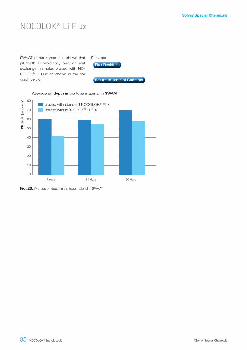
Solvay Special Chemicals
85 NOCOLOK® Encyclopedia ©Solvay Special Chemicals
NOCOLOK® Li Flux
SWAAT performance also shows that pit depth is consistently lower on heat exchanger samples brazed with NO-COLOK® Li Flux as shown in the bar graph below:
See also:
Fig..20: Average pit depth in the tube material in SWAAT
0
20
30
70
80
7 days
Average pit depth in the tube material in SWAAT
10
40
50
60
14 days 20 days
brazed with standard NOCOLOK® Fluxbrazed with NOCOLOK® Li Flux
Pit
dep
th [m
icr
ons
]
Flux Residues
Return to Table of Contents

Solvay Special Chemicals
86 NOCOLOK® Encyclopedia ©Solvay Special Chemicals
Heat exchanger manufacturers often use zinc-coated extruded tubes as a means of offering additional corrosion protection. Zinc deposited on the sur-face of the tube diffuses into the alumi-num surface during brazing to create a zinc rich layer. This layer offers sacri-ficial protection to the core. Corrosion will proceed first in this Zn rich layer and completely consume this layer, before proceeding through the thickness of the core. In other words, corrosion on the tube is restricted to the Zn rich layer, de-laying perforation.
NOCOLOK® Zn Flux offers an alterna-tive to depositing elemental Zn on the aluminum surface. It is a fine white pow-der with the chemical formula KZnF3. NOCOLOK® Zn Flux is also known as a reactive flux as it only becomes active at brazing temperature and in contact with aluminum. Pure KZnF3 decomposes at temperatures above 700°C. However, in contact with an aluminum substrate, this material initiates a series of reactions be-ginning at around 565°C:
6KZnF3.+.4Al........6Z.+.3KAlF4.+.K3Al.F6
Note that a pseudo-flux is created along with elemental Zn from the KZnF3. The flux then dissolves the oxides present on Al. During this period, the Zn diffuses into the surface of the base component, thus creating a Zn rich layer analogous to that produced by arc-sprayed Zn.
The coating process for NOCOLOK® Zn Flux which can include spraying, dip-ping, painting or electrostatic coating, can be adjusted to provide exactly the same Zn diffusion profile as that for arc-sprayed Zn. Furthermore, this material allows the deposition of precise Zn lev-els, much more controlled than that of arc-sprayed Zn.
The following schematics shows the progression and mechanism of Zn dif-fusion before, during and after brazing:
NOCOLOK® Zn Flux
Currently, the main fields of application for NOCOLOK® Zn Flux are for the production of automotive condensers and the next generation of micro-channel evaporators.
See also:
Fig..21: NOCOLOK® Zn Flux: before, during and after brazing
Zn Sacrifical Protection
Return to Table of Contents

Solvay Special Chemicals
87 NOCOLOK® Encyclopedia ©Solvay Special Chemicals
NOCOLOK® Sil Flux, NOCOLOK® Li Flux and NOCOLOK® Zn Flux have all been proven to work individually, but what about combinations of two or even all three fluxes together?
In theory there is no reason why they should not work together. One must only ensure that combinations of one or more of these fluxes take into account the re-sulting load (as measured in g/m2) of each individual component of interest so that each component can accomplish its intended function:
• Sufficient flux to dissolve the oxide film
• Sufficient Zn to create a reasonable Zn-rich layer
• Sufficient Si to create filler metal
At the same time however, one must al-so ensure that the resulting flux load of such combinations is not so high as to impede the function of each component of interest.
It is worth mentioning that combina-tions are not limited to just NOCOLOK® Sil Flux, NOCOLOK® Li Flux and NO-COLOK® Zn Flux. Additions to standard NOCOLOK® Flux of Si powder, Al-12% Si powder, hypereutectic Al-Si alloy powders and Zn powder have all been investigated and some cases even cur-rently used in production. Again the criti-cal factor here is that the addition of any of the above components is sufficient to accomplish its intended function without causing unintended consequences.
See also:
NOCOLOK® Sil Flux, NOCOLOK® Li Flux, NOCOLOK® Zn Flux: Combinations and Permutations?
NOCOLOK® Zn Flux
NOCOLOK® Li Flux
NOCOLOK® Sil Flux
Return to Table of Contents

31/4
25/0
9.13
/007
/PD
F
www.solvay.com
EuropeSolvay Fluor GmbHPostfach 220 30002 Hannover, GermanyTelephone: +49 511 857-0 Fax: +49 511 857-2146
North AmericaSolvay Fluorides, LLC3333 Richmond AvenueHouston, TX 77098, USATelephone: +1 713 525-6000 Fax: +1 713 525-7805
Asia/PacificSolvay Korea CO., LTD5th Fl. Donghwa Bldg.58-7, Seosomun-Dong, Jung-Gu Seoul, 100-736, KoreaTelephone: +82 2 751 3509 Fax: +82 2 751 3576
Disclaimer: All statements, information, and data given herein are believed to be accurate and reliable but are presented without guarantee, warranty or responsibility of any kind, express or implied. Statements or suggestions concerning possible use of our products are made without representation or warranty that any such use is free of patent infringement, and are not recom-mendations to infringe any patent. The user should not assume that all safety measures are indicated, or that other measures may not be required. In any case, the user is not exempt from observing all legal, administrative and regulatory procedures relating to the product, personal hygiene, and protection of human welfare and the environment.w
ww
.ahl
ersh
eine
l.de