object-oriented modeling for flexible manufacturing systems
TRANSCRIPT

P1: NEL
The International Journal of Flexible Manufacturing Systems KL627-05-BOOTH September 21, 1998 11:40
The International Journal of Flexible Manufacturing Systems, 10 (1998): 301–314c© 1998 Kluwer Academic Publishers, Boston. Manufactured in The Netherlands.
Object-Oriented Modelingfor Flexible Manufacturing Systems
ALEXANDER W. BOOTHSchool of Mathematics and Computing, University of Derby, UK
Abstract. Object-oriented modeling provides a new way of thinking about flexible manufacturing systems,using models organized around real-world concepts. This paper describes how the object modeling technique canbe used to develop integrated factory models that embrace factory process modeling as well as policy modeling.Such models can be used to assess how quickly a manufacturing organization can adjust its operations to meetchanges in demands for products, consumer preferences, supplier quality, and lead times. These models also canbe used as vehicles for studying the impact of introducing new product lines or new process technology withoutthe disruption or expense of pilot projects or test setups.
Key Words: object-oriented analysis and design, object modeling, abstraction
1. Introduction
While cost and quality always have been considered critical success factors in the manu-facturing industry, flexibility also has become increasingly important (Kim, 1991). If weview flexibility as that quality which allows a manufacturer to quickly adapt its operationsto meet the needs of changing conditions and competitive environments, it can be helpful todistinguish between operational flexibility and strategic flexibility. Operational flexibilitydeals with short-term issues such as changes in product and volumes, whereas strategicflexibility deals with longer-term policy issues such as changes in process technology oropening a new factory (Cohen and Zysman, 1987). Ideally, it would be beneficial to studythe effects of both kinds of changes before they occur and before any investment has beenmade or any errors introduced. This is where modelling and simulation can prove veryuseful.
Model-based approaches to flexible manufacturing systems (FMSs) are not new andresearch in this area is increasing (Aguiar and Weston, 1995). Although modeling andsimulation tools have been around for some time to assist manufacturers in the analysis ofprocess operation and the prediction of performance (Sabuncuoglu, 1995), they are only asgood as the built model; that is, the abstraction of the real-world situation, which is usedin simulation runs to study behavior, make comparisons and draw conclusions. In otherwords, the analysis of the manufacturing enterprise—the people, processes, and products,at the necessary levels of abstraction (e.g., operational or strategic)—is most important,because only when this is accomplished can the right tool be selected to represent andstudy the behavior of the model(s). Object-oriented modeling is a new way of thinkingabout problems, using models organized around real-world concepts (Rumbaugh et al.,

P1: NEL
The International Journal of Flexible Manufacturing Systems KL627-05-BOOTH September 21, 1998 11:40
302 ALEXANDER W. BOOTH
1991; Booch and Rumbaugh, 1995). As Rumbaugh et al. (1991) explain, “Object-orientedmodels are useful for understanding problems, communicating with application experts,modelling enterprises, preparing documentation, and designing programs and databases.”
The modern manufacturing organization can be quite complex, consisting of networksof factories interconnected by high-technology telecommunication links, with client/serverarchitectures housing various kinds of databases, and computer-aided manufacturing ap-plications. Although simulation tools exist for modeling factories, telecommunicationnetworks, business process reengineering, and logistics, it is difficult to know which toolto apply to which set of problems and whether or not results from one simulation can driveanother. Too often, the wrong tool is used for the wrong task or the modeler strugglesto represent his or her problem within the limitations of a “standard” modeling packagethat is just not capable of the task. In addressing the issue of manufacturing flexibility, itis essential that models be built at the correct level of abstraction to study the effects ofoperational and strategic changes.
2. Abstraction
In the context of developing a model to study manufacturing flexibility and the processesinvolved in developing a product, it is important to be clear about what is meant by thetermsabstraction, process, and model. The goal ofabstractionis to isolate those as-pects important to the system under study and suppress (or abstract out) those aspects thatare unimportant. Hereprocessmeans a systematic approach to the creation of a productor the accomplishment of some task. It is reasonable to assume that a set of activitiesundertaken to manufacture a product or provide a service can be considered a process. Weuse the generally accepted interpretation ofmodelas being an abstraction of something forthe purpose of understanding it. In building a model to study manufacturing flexibility,one does not search for absolute truth but for adequacy to satisfy the purpose. This kindof abstraction results in an “outside” view, which finds a natural implementation in theobject-oriented approach and the concept of encapsulation; that is, encapsulation preventsclients seeing the “inside” view of an object and thereby provides explicit barriers amongdifferent abstractions.
2.1. Levels of abstraction
All models are abstractions of the real world and it is the modeler’s responsibility to isolatethose aspects that are important to the purpose of the model. If the purpose of a modelis to answer questions of the type “What is the effect of transport interference?” “Howimportant is the variability of machine times?” or “Can we open another conveyor beltto get these boxes out by 10.00P.M. this evening?” then we need to represent transportsystems, machines, and conveyor belts, for example, in terms of their capacity and rate (i.e.,operationally). Similarly, if the purpose of the model is to answer questions of the type“Should we close down the factory in location P?” “Should we introduce product X ontothe market next year?” or “Should we buy our raw materials from a different supplier nextyear?” then we need to work at a level of abstraction that allows us to represent real-world
P1: NEL
The International Journal of Flexible Manufacturing Systems KL627-05-BOOTH September 21, 1998 11:40
OBJECT-ORIENTED MODELING 303
objects in terms of their attributes and behavior, which relate to strategic issues. Of course,if we need to answer both types of questions in the same model, then we can work at multiplelevels of abstraction but with clear intent of the use of objects.
3. Object modeling technique
Object modeling technique (OMT) is gaining increasing recognition as a powerful androbust system development methodology as evidenced by the availability of commercialcomputer-aided software engineering tools to support OMT object-oriented analysis anddesign environments (e.g.,Rational Rose 3.0, 1996) as well as the number of recent pub-lications in journals and conferences; some examples are Rumbaugh (1996), Booch andRumbaugh (1995), Bourdeau and Cheng (1995), and Oliver (1994). As Rumbaugh et al.(1991) explain, the OMT approach views a system from three related but different view-points, each capturing important aspects of the system, but all required for a completedescription. The object model represents the static, structural aspects of the system, inwhich objects, their identity, their attributes, their relationship to other objects, and theiroperations all are described in detail. The dynamic model represents the temporal, behav-ioral aspects of a system, in which changes marked by events, sequences of events, statesthat define the context for events, and the organization of events and states all are described.The functional model represents the transformational aspects of a system and captures whatthe system does without regard forhowor whenit does it.
3.1. Object model for a flexible manufacturing system
As mentioned previously, the object model is concerned with the static, structural aspectsof a system: objects, identity, attributes, relationships, and operations. Let us consider aslightly modified version of the flexible manufacturing system studied by Pelegagge andCardarelli (1996), shown in figure 1. The system comprises the following:
∗ six machines equipped with one of three different types of operating machine(L ,M, N)and sequential input and output buffers.∗ automatic loading/unloading systems and operators.∗ direct-access interoperational storage.∗ single-channel material handling system, such as a track robot.∗ direct-access input warehouse (four buffers, one for each part typeA, B,C, andD).
The flow of parts through the system is according to a job shop scheme (see Pelegaggeand Cardarelli, 1996, for details). Essentially, a part group consists of a number of partsscaled proportionally to the minimal part set (MPS); that is, the smallest part set that satisfiesthe desired produced part mix ratio. A new group is put into the input warehouse only whenthere are no more parts from the preceding group.
Object identification. During analysis of the FMS, the following candidate classes ofobjects were identified: workstations, machines, buffers, interoperational store, track robot,

P1: NEL
The International Journal of Flexible Manufacturing Systems KL627-05-BOOTH September 21, 1998 11:40
304 ALEXANDER W. BOOTH
Figure 1. FMS layout.
products, parts, warehouse, loading systems, operators, and job group. OMT is rich ingraphic symbols; and class diagrams, for example, consist of a box with three sections. Thefirst section contains the class name, the second contains the attributes of objects in thatclass, and the third contains the operations (or behavior) performed by objects in that class.The examples in figure 2 of class definitions, with attributes and operations, represent alevel of abstraction that allows users to study the operational aspects of an FMS, such asutilization, work in progress, job scheduling, and contingency planning.
Object association. Once the objects in the manufacturing organization have been identi-fied, the next step in OMT is to deal with how they relate to each other, that is, associations.Here, we adhere very closely to the Rumbaugh et al. idea of expressing relationships, where“Any dependency between two or more classes is an association. A reference from oneclass to another is an association.” In OMT the graphic notation for an association is aline between two classes. Multiplicity (e.g., one-to-many, many-to-many relationships) isshown as a circle at the end of the lines. In figure 3, we see a black dot at the end of a linefrom the interoperational store to the parts class, with the wordholdsnext to the line. Thismeans that the interoperational store holds many (none or more) parts. The line between theinteroperational store and the track robot has no dots, which conveys a one-to-one relation-ship. The association nameloadsparts is written above the line. Ideally, the associationname should be written above the line and the role of each class in the association be writtennext to the class box; see Rumbaugh et al. (1991).
We allow no classes to be attributes of other objects but express those types of relation-ships as associations. Aggregation is a special form of association with extra semantics.Aggregation is the “a-part-of” relationship in which objects representing the compo-nents of something are associated with an object representing the entire assembly. InOMT, aggregation is drawn like association except a small diamond indicates the assemblyend of the relationship. In figure 3, we see that a Warehouse is made up of many input

P1: NEL
The International Journal of Flexible Manufacturing Systems KL627-05-BOOTH September 21, 1998 11:40
OBJECT-ORIENTED MODELING 305
Figure 2. Object classes for an FMS.
Figure 3. FMS associations.
buffers and one output buffer and that a Workstation is composed of an operating machine,one input buffer, and one output buffer.
Other relationships (associations) expressed in figure 3 include a Track Robot being ableto transport many parts but each part being transported by a single track robot; Machines canwork on many parts and parts can be worked on by multiple machines (but not at the same

P1: NEL
The International Journal of Flexible Manufacturing Systems KL627-05-BOOTH September 21, 1998 11:40
306 ALEXANDER W. BOOTH
Figure 4. Object simplification using inheritance.
time); Input and Output Buffers can hold many parts and parts can be held in multiple inputand output buffers. Sometimes, it is useful to model associations as classes themselves,which have attributes and behavior relating to the relationship and not just to either typeof object. For example, to represent the job shop scenarios of Pelagagge and Cardarelli,we can elaborate on the preceding machines/parts relationship and create job shop scenarioand working cycle classes. Figure 4 allows us to represent a job shop scenario consistingof four part types. Part typeA, for example, comprises 50% of the part-mix percentage, hasfour parts in the group, each with four work cycles. In the first work cycle, partA spends10 minutes on machineL1, the second 5 minutes on machineL2, the third 20 minuteson machineN1, and the fourth 15 minutes on machineN2 (this can be compared withTable 1 of Pelagagge and Cardarelli, 1996). As machines spend a different amount of timeon different parts, “machining time” is an attribute of the association class “working cycle.”
Object inheritance and reuse.The next step is to simplify the object classes by usinginheritance. Figure 2 does not show inheritance hierarchies. Inheritance can be added bygeneralizing common aspects of existing classes into a superclass from which commonfeatures are shared. With inheritance, attributes and operations common to a group ofsubclasses are attached to the superclass and shared by each subclass. The most commonreason for using inheritance is that it simplifies the reuse of code. The basic idea underlyingreuse is that, rather than build each system from scratch, we should take advantage ofthe similarities between systems. Studies of software systems have shown that 60% ofone system is likely to be similar to another in design and code. Reuse of objects insimulation models is just as important as reuse in other software engineering applications.Not only can we reuse classes produced from objects that have common features, butthe advantages of reuse can be gained from building a class library from which objectscan be reused directly or as the foundation for other objects. In OMT, the notation forinheritance is a triangle connecting a superclass to its subclasses. One obvious example fromthe classes in figure 2 is that of machines. In figure 5, we observe that all classes of machinehave the common attributes of maintenance costs, operating costs, and the like, but onlyL-type machines have the attribute accuracy threshold. Similarly, all classes of machinehave common behavior even thoughL ,M , and N implement the machining operationdifferently. This is an example of object-oriented polymorphism; that is, one interface but

P1: NEL
The International Journal of Flexible Manufacturing Systems KL627-05-BOOTH September 21, 1998 11:40
OBJECT-ORIENTED MODELING 307
Figure 5. Object simplification using inheritance.
many implementations. In addition, onlyL-type machines have extra behavior related toaccuracy. Another example of inheritance from the classes in figure 2 is that of materialhandling systems. A track robot, for example, is a special kind of material handling systemand therefore would inherit all the attributes and behavior common to all material handlingsystems. If we now wished to specify the attributes and behavior of an automatic guidedvehicle (AGV), for example, we could inherit the existing attributes and behavior of thesuperclass of material handling system and add the extra attributes and behavior peculiarto AGV-type handling systems (figure 6).
3.2. The functional model
As mentioned earlier, the functional model is concerned with the transformational aspectsof a system: what the system does without regard for how or when it does it. The functionalmodel can be represented by data flow diagrams that show inputs and outputs for eachfunction and the meaning of operations and constraints. We consider an example data flowdiagram in Section 3.4, where we consider the strategic aspects of the FMS. Data flowsshow the possible computation paths for values, they do not show which paths are executedor in what order; this is addressed in the dynamic model.
3.3. The dynamic model
Data flow diagrams in the functional model show what the system does without regardfor when it does it. The dynamic model completes the picture by showing those aspectsconcerned with time and the sequences of operations. Traditionally, control flow diagrams(CFDs) have been used to represent control issues such as decisions and sequences. A controlflow is a Boolean value that affects whether a process is evaluated, and it is indicated by

P1: NEL
The International Journal of Flexible Manufacturing Systems KL627-05-BOOTH September 21, 1998 11:40
308 ALEXANDER W. BOOTH
Figure 6. Material handling systems, simplification using inheritance.
a dashed line. Figure 7 shows a control flow diagram for our track robot object and isconsistent with Pelagagge and Cardarelli (1996). In figure 7, processes are represented bybubbles (i.e., circles), andw/s is an abbreviation for workstation.
While in OMT, it is occasionally useful to use CFDs, it is more common to use statetransition diagrams (STDs) to represent the dynamic model. Each state diagram is intendedto show, for one class of objects, the states and event sequences permitted. State diagramsare used to link the dynamic model with the object and functional models in thateventsin the state diagrams correspond to operations in object diagrams, andactionsin the statediagrams correspond to functions in the data flow diagrams. Figure 8 shows an equivalentSTD for the track robot control flow of figure 7.
As one might expect, in enhancing the model to study strategic flexibility, we very quicklyencounter complex associations (see figure 9). We already have seen in the operationaldescription of the FMS that machines can perform a range of operations on various partsin the process of developing a product. Parts are assembled in different configurations toproduce different product types. Different machines have different capabilities in termsof which raw materials they can handle. Added to this we must now consider that somesuppliers supply only one raw material, other suppliers supply several raw materials. Thereis no single sourcing.
Certain products are delivered to certain types of outlets; not all products go to alloutlets. Not all factories are capable of manufacturing all product types. The relationshipsexpressed in figure 10 include a factory having many (none or more) outlets and each outletsupporting many factories; a factory works on many part types and each part type can beworked on at multiple factories. Similarly, factories develop many products and productscan be developed at many factories. Figure 10 allows the following relationships to be

P1: NEL
The International Journal of Flexible Manufacturing Systems KL627-05-BOOTH September 21, 1998 11:40
OBJECT-ORIENTED MODELING 309
Figure 7. Control flow diagram for the track robot.
Figure 8. State transition diagram for the track robot.

P1: NEL
The International Journal of Flexible Manufacturing Systems KL627-05-BOOTH September 21, 1998 11:40
310 ALEXANDER W. BOOTH
Figure 9. Factory, product, and marketing information classes.
Figure 10. Associating factory, supplier, raw materials, outlet, product, and part type.
instantiated:
Factory Supplier Raw material Part type Product Outlet
LocationP S1 R1 A ProdX Outlet 1
LocationP S1 R1 A ProdY Outlet 1
LocationP S1 R1 A ProdZ Outlet 1
LocationP S1 R2 B ProdX Outlet 1
LocationQ S2 R2 B ProdX Outlet 1
LocationQ S2 R2 C ProdW Outlet 2
LocationQ S2 R3 D ProdV Outlet 2
LocationQ S2 R3 D ProdT Outlet 3
At this point in OMT, we have not even began to consider a tool that will allow us torepresent this flexibility but only an object model of a factory at a level of abstraction thatallows us to tackle operational and strategic issues. Although this is a much simplifiedexample, by representing the model in this way, we start to get an increased awareness of

P1: NEL
The International Journal of Flexible Manufacturing Systems KL627-05-BOOTH September 21, 1998 11:40
OBJECT-ORIENTED MODELING 311
what might be involved in “closing down the factory at location P”! Also, by representingan organization by objects with attributes and behavior, we get a better handle on thosecharacteristics that distinguish FMS from conventional equipment; characteristics suchas mechanization, reprogrammable automation, integration, complexity, regulation, andexpense (Boer, 1994).
3.4. Expanding the functional model
A set of data flow diagrams for a typical product development cycle are shown in figure 11.The bubbles in the level 1 data flow diagram correspond to activity objects, whereas thebubbles in lower-level data flow diagrams correspond to actions/services provided by thoseobjects.
Level 2 data flow diagrams. Figure 12 shows a level 2 data flow diagram for a simplifieddevelopment activity of the product development process. The bubbles in this diagram
Figure 11. Level 1 data flow diagram for product development.
Figure 12. Data flow diagram of the development activity.
P1: NEL
The International Journal of Flexible Manufacturing Systems KL627-05-BOOTH September 21, 1998 11:40
312 ALEXANDER W. BOOTH
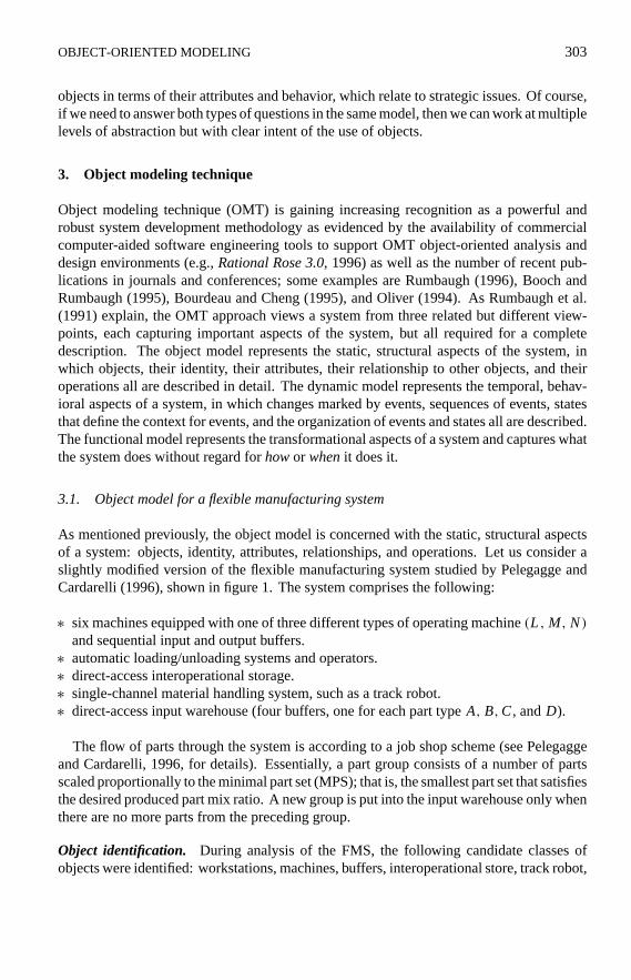
Figure 13. Simplified state transition diagram of the development activity.
correspond to actions/services provided by those objects. The actual flows on the data flowdiagrams correspond to attribute values in the object diagrams.
3.5. Expanding the dynamic model
As mentioned earlier, although data flow diagrams in the functional model show what thesystem does without regard for when it does it, state transition diagrams in the dynamicmodel complete the picture by showing temporal aspects of the system. So, whereas figure12 shows what is happening in the development activity, figure 13 shows when it happens.
The combination of the object model, functional model, and dynamic model provides acomplete and documented description of the manufacturing enterprise. The model can bemodified and refined with increases in understanding of the processes and products, espe-cially as they relate to flexibility. The successful model should demonstrate that FMS havemade it quicker, easier, and cheaper to incorporate enhanced features into products (Peppard,1993). The collection of object diagrams, dataflow diagrams, and state transition diagramsform the basis for implementation of the model using computer simulation. Selecting theright simulation language, package, or tool is now the next most important step.
4. Selecting a simulation language or tool
Once the object model, functional model, and dynamic model are fairly complete, consid-eration can be given to the selection of a modeling tool or language. Basically, four choicesare available (Jain, 1991): a general-purpose language, an extension of a general-purpose

P1: NEL
The International Journal of Flexible Manufacturing Systems KL627-05-BOOTH September 21, 1998 11:40
OBJECT-ORIENTED MODELING 313
language, a simulation language, or a simulation package. We now consider each of thesein turn.
A general purpose language such as FORTRAN or C might be chosen for simulationpurposes because of a programmer’s familiarity with such languages. Although this choicedoes not require learning a new language, considerable time will be spent in developinggeneral simulation facilities such as event scheduling, advancing simulation time, randomnumber generation, statistical data gathering, entity/object manipulation, and report genera-tion. An extension of a general purpose language that incorporates additional functionalitycan be attractive, especially if the extensions are object oriented, as in the case of C++.However, the general simulation facilities described previously still need to be developed.GASP, on the other hand is not object oriented but is an extended FORTRAN with built-in simulation facilities for event scheduling and time advancement. Simulation languageshave the built-in facilities and offer the advantage of less distraction from issues that aregeneral to all simulations, which leaves more time to focus on the important issues spe-cific to the factory or organization being modeled. Languages such as SIMSCRIPT andMODSIM (1993) allow for modular code development but still involve programmers devel-oping the model. The fourth choice is a simulation package that, in many cases, will allowone to develop a model and see results in a few days as opposed to weeks or months for asimulation language. The disadvantage is the lack of flexibility and always having to workwithin the limitations of the package: they provide for only those features foreseen by theirdevelopers. SIMFACTORY II.5 (1993), for example, is an easy to use, menu-driven anal-ysis tool that predicts factory performance through simulation, and provides an animatedpicture of the factory in action. SIMFACTORY II.5 requires no programming and is usefulfor such things as workflow analysis, product mix analysis, WIP inventory projections,and product cost estimation. This is just one of many packages on the market, but suffersfrom the limitations mentioned earlier. However, a new era of simulation packages willallow for the integration of externally developed modules (using a simulation language)into the package, thus having the best of both worlds. COMNET III, for example, has takenthis approach. Although COMNET III is aimed at modeling telecommunication networks,whereas SIMPROCESS and SIMFACTORY (also from CACI) are aimed at modeling busi-nesses and factories, we can expect to see increased “flexibility” in modeling tools that needto model manufacturing flexibility.
5. Conclusions
This paper has described how object-oriented modeling can provide a new way of thinkingabout flexible manufacturing systems using models organized around real-world concepts.The advantages of this approach are as follows: (1) the object is the single unifying conceptin the process of developing models of flexible manufacturing systems at both operationaland strategic levels; (2) because data structure and behavior are encapsulated in a singleentity, problems of interdependency, where small changes in a model produce massiveripple effects, are less likely; (3) the potential exists to develop class libraries of objectsto be used in models to study both operational and strategic issues and such libraries willprovide significant benefits through the reuse of objects; and (4) because more attention

P1: NEL
The International Journal of Flexible Manufacturing Systems KL627-05-BOOTH September 21, 1998 11:40
314 ALEXANDER W. BOOTH
is focused on the structure of real-world objects (rather than the functions they perform),a more stable base for developing computer simulation models of flexible manufacturingsystems is achieved. Once the right tool or language has been selected to represent themodel, strategic and operational flexibility can be studied without the disruption or expenseof pilot projects or test setups.
References
Aguiar, M. and Weston, R., “A Model-Driven Approach to Enterprise Integration,”International Journal ofComputer Integrated Manufacturing, Vol. 8, No. 3, pp. 210–224 (1995).
Banker, R., Kauffman, R., and Zweig, D., “Repository Evaluation of Software Reuse,”IEEE Transactions onSoftware Engineering and Methodology, Vol. 19, No. 4, pp. 379–389 (1993).
Boer, H., “Flexible Manufacturing Systems,” inNew Wave Manufacturing Strategies, John Story (Ed.), PaulChapman Publishing Ltd., London, UK (1994).
Booch, G. and Rumbaugh, J.,Unified Method for Object-Oriented Development, Rational Software Corporation,CA (1995).
Bourdeau, R.H. and Cheng, B.H.C., “A Formal Semantics for Object Model Diagrams,”IEEE Transactions onSoftware Engineering, Vol. SE-21, No. 10 (October 1995).
Cohen, S.S. and Zysman, J.,Manufacturing Matters, Basic Books, New York, NY (1987).COMNET (simulation package), CACI, La Jolla, CA (1993).Jain, R.,The Art of Computer Systems Performance Analysis, Wiley Professional Computing, John Wiley and
Sons, New York, NY (1991).Kim, C., “Issues on Manufacturing Flexibility,”Integrated Manufacturing Systems, Vol. 2, No. 2, pp. 4–13 (1991).Oliver, D.W., “Systems Engineering and Object Technology,” 4th Annual Symposium of the National Council on
Systems Engineering, CA (August 1994).Pelagagge, P.M. and Cardarelli, G., “An Effective Loading Rule for FMS Real Time Scheduling,”Integrated
Manufacturing Systems, Vol. 7, No. 1, pp. 52–59 (1996).Peppard, J., “Using IS/IT to Gain Competitive Advantage,” inI.T. Strategy for Business, Pitman Publishing Ltd.,
London, UK (1993).Rational Rose 3.0, Rational Software Corporation, CA (1996).Rumbaugh, J., “To Form a More Perfect Union—Unifying the OMT and Booch Methods,”Journal of Object-
Oriented Programming, Vol. 8, No. 8, pp. 14–18 (1996).Rumbaugh, J., Blaha, M., Premerlani, W., Eddy, F., and Lorensen, W.,Object-Oriented Modeling and Design,
Prentice-Hall, Englewood Cliffs, NJ (1991).Sabuncuoglu, I. and Hommertzheim, D., “Experimental Investigation of an FMS Due-Date Scheduling Problem:
Evaluation of Machine and AGV Scheduling Rules,”International Journal of Flexible Manufacturing Systems,Vol. 5, pp. 301–323 (1993).
Sabuncuoglu, I. and Hommertzheim, D., “Experimental Investigation of an FMS Due-Date Scheduling Problem:An Evaluation of Due-Date Assignment Rules,”International Journal of Computer Integrated Manufacturing,Vol. 8, No. 2, pp. 133–144 (1995).
Select OMT Professional, Select Software Tools Inc., CA (1996).SIMSCRIPT and MODSIM (simulation languages), CACI, La Jolla, CA (1993).SIMFACTORY and SIMPROCESS (simulation packages), CACI, La Jolla, CA (1993).