object-oriented design of real-time systems purpose
TRANSCRIPT
1
94.586 Object-Oriented Design of Real-time Systems...Winter 2001 A-1Copyright C. M. Woodside 2000
Object-oriented Design of Real-time Systems
Purpose
• Architecture and behaviour–architecture families and issues
• Specifying behaviour–at the system level (use cases, collaborations, Use Case Maps)–at the module level (state machines)–developing module specs from system requirements
• Concurrency and architecture–developing specifications
94.586 Object-Oriented Design of Real-time Systems...Winter 2001 A-2Copyright C. M. Woodside 2000
Types of real-time systems
• reactive to continuous signals.... for instance
– signal processing (speech and radar processing)
– control systems (aircraft, cruise control, factory automation)
• reactive to discrete events.... for instance
– elevator control, telephony
• data request handling.... for instance
– web-based systems (e-commerce)
– transaction processing (point-of-sale, banking)
– client-server systems
2
94.586 Object-Oriented Design of Real-time Systems...Winter 2001 A-3Copyright C. M. Woodside 2000
Typical architectural/behavioral designsolutions
• in each of these domains we shall study commonly-used patterns forthe architecture and behavior of designs
– nature of solution
– strengths, when to apply it
• we shall also consider extensions and alternatives
– additional concurrency in asynchronous designs
– replication
94.586 Object-Oriented Design of Real-time Systems...Winter 2001 A-4Copyright C. M. Woodside 2000
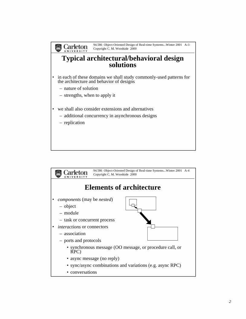
Elements of architecture
• components (may be nested)
– object
– module
– task or concurrent process
• interactions or connectors
– association
– ports and protocols
• synchronous message (OO message, or procedure call, orRPC)
• async message (no reply)
• sync/async combinations and variations (e.g. async RPC)
• conversations
3
94.586 Object-Oriented Design of Real-time Systems...Winter 2001 A-5Copyright C. M. Woodside 2000
ADLs and ROSE-RT tool (Architecture description language, e.g. Aesop, Newton, ACME)
• ROSE-RT uses UML (OMG standard) to define architecture:
– UML classes and associations to define components andinteractions
– UML aggregation to show nested components
– R-RT protocol to define the nature of the interaction
• switches to a special CAPSULE model to define behaviour
– a capsule is a component, (== class)
• all capsules are potentially concurrent
– a port is the attachment of a protocol/interaction
– a state machine defines behavior of the capsule
• reacts to events on ports, puts out events, computes
94.586 Object-Oriented Design of Real-time Systems...Winter 2001 A-6Copyright C. M. Woodside 2000
ADLs and SDL (TAU tool)
• SDL = Specification and Description Language
– ITU standard
– linked with Message Sequence charts, also an ITU standard
• components are processes
• connections are connections with signal-lists• all interactions are async
– synchronous interactions can be built up from async
4
94.586 Object-Oriented Design of Real-time Systems...Winter 2001 A-7Copyright C. M. Woodside 2000
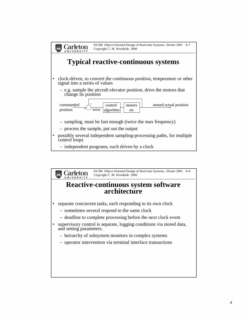
Typical reactive-continuous systems
• clock-driven, to convert the continuous position, temperature or othersignal into a series of values
– e.g. sample the aircraft elevator position, drive the motors thatchange its position
– sampling, must be fast enough (twice the max frequency)
– process the sample, put out the output
• possibly several independent sampling-processing paths, for multiplecontrol loops
– independent programs, each driven by a clock
control algorithm
commandedposition error
sensed actual position-+
motorsetc
94.586 Object-Oriented Design of Real-time Systems...Winter 2001 A-8Copyright C. M. Woodside 2000
Reactive-continuous system softwarearchitecture
• separate concurrent tasks, each responding to its own clock
– sometimes several respond to the same clock
– deadline to complete processing before the next clock event
• supervisory control is separate, logging conditions via stored data,and setting parameters.
– heirarchy of subsystem monitors in complex systems
– operator intervention via terminal interface transactions
5
94.586 Object-Oriented Design of Real-time Systems...Winter 2001 A-9Copyright C. M. Woodside 2000
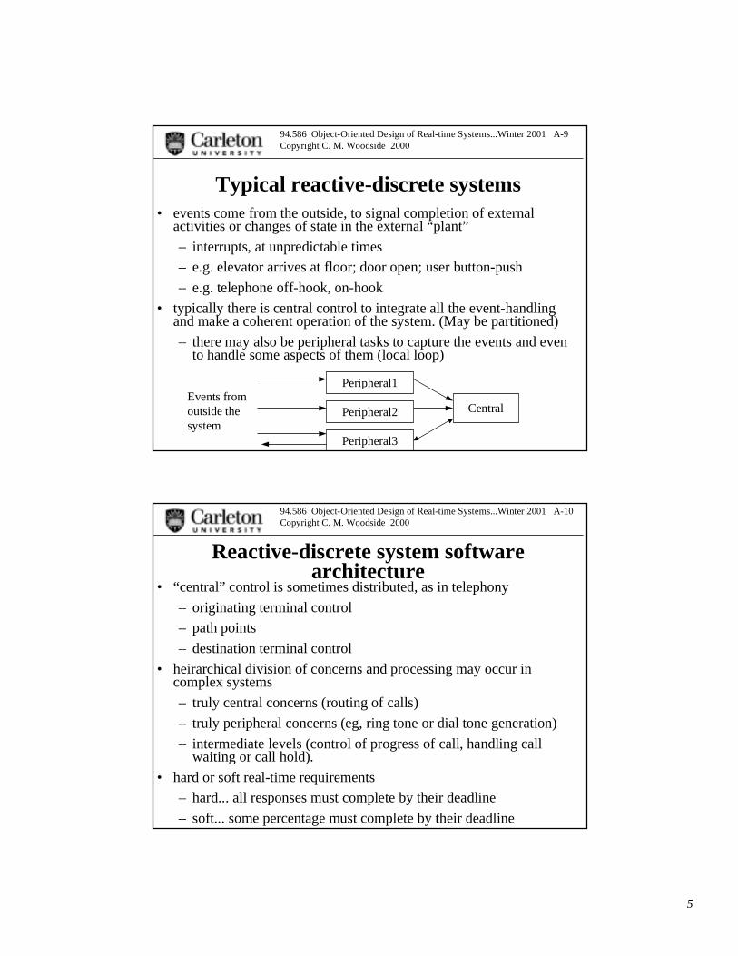
Typical reactive-discrete systems• events come from the outside, to signal completion of external
activities or changes of state in the external “plant”
– interrupts, at unpredictable times
– e.g. elevator arrives at floor; door open; user button-push
– e.g. telephone off-hook, on-hook
• typically there is central control to integrate all the event-handlingand make a coherent operation of the system. (May be partitioned)
– there may also be peripheral tasks to capture the events and evento handle some aspects of them (local loop)
Central
Peripheral1
Peripheral2
Peripheral3
Events fromoutside the system
94.586 Object-Oriented Design of Real-time Systems...Winter 2001 A-10Copyright C. M. Woodside 2000
Reactive-discrete system softwarearchitecture
• “central” control is sometimes distributed, as in telephony
– originating terminal control
– path points
– destination terminal control
• heirarchical division of concerns and processing may occur incomplex systems
– truly central concerns (routing of calls)
– truly peripheral concerns (eg, ring tone or dial tone generation)
– intermediate levels (control of progress of call, handling callwaiting or call hold).
• hard or soft real-time requirements
– hard... all responses must complete by their deadline
– soft... some percentage must complete by their deadline
6
94.586 Object-Oriented Design of Real-time Systems...Winter 2001 A-11Copyright C. M. Woodside 2000
Mixed continuous and discrete systems
• control systems often also have event reaction subsystems
– e.g. a fire alarm or a passenger button-push, on an aircraft
• similarly a primarily event-driven system may have clock events thatcause conditions to be polled
• clocked processing may raise exceptions that are then unpredictablediscrete events for further processing
94.586 Object-Oriented Design of Real-time Systems...Winter 2001 A-12Copyright C. M. Woodside 2000
Typical data request handling systems
• essential unit of processing is a transaction
– a “strong” transaction has ACID properties
• atomicity (parts are indivisible)
• consistency (satisfies some properties that prevent errors)
• isolation (equivalent to serial execution)
• durability (crash-resistant)
– a “weak” transaction is a request for processing, without so manyguarantees (e.g. a web page request).
• common factor is a user request, with data, and with multiple possibleprocessing paths.
• usually has soft real-time requirements (e.g. 95% of responsescomplete within T sec). (Hard-real-time requirements exist too)

7
94.586 Object-Oriented Design of Real-time Systems...Winter 2001 A-13Copyright C. M. Woodside 2000
Request-handling system architecture
• often client-server, including multi-tier CS....
– Call return RPC infrastructure
App-UI
Data Server Data Server
App ServerApp Server
App App
App-UI
94.586 Object-Oriented Design of Real-time Systems...Winter 2001 A-14Copyright C. M. Woodside 2000
Request-handling: Banking system... Use Cases
• simple ATMsystem to executea singletransaction:
– validate PIN,do operation
– Gomaaexample.....
8
94.586 Object-Oriented Design of Real-time Systems...Winter 2001 A-15Copyright C. M. Woodside 2000
• states aresystem states
– waiting foran event
– processing
• transitions arereactions toevents or toresult ofprocessing
• “validate PIN”Use Case asstate machine...
ATM... unbound state machine for behaviour
94.586 Object-Oriented Design of Real-time Systems...Winter 2001 A-16Copyright C. M. Woodside 2000
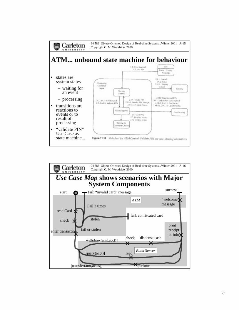
Use Case Map shows scenarios with MajorSystem Components
start
read Card
check
fail or stolen
Fail 3 times
enter transaction
[withdraw(amt,acct)]
[query(acct)]
[transfer(amt,accts)]
check dispense cash
read
perform
fail: “invalid card” message
fail: confiscated cardstolen
success
printreceiptor info
ATM
Bank Server
“welcome” message
9
94.586 Object-Oriented Design of Real-time Systems...Winter 2001 A-17Copyright C. M. Woodside 2000
ATM side... Details: collaboration diagram
• roles andinteractions
• controller
• devices:
– card reader
– cashdispenser
– printer
94.586 Object-Oriented Design of Real-time Systems...Winter 2001 A-18Copyright C. M. Woodside 2000
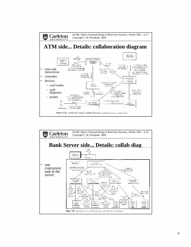
Bank Server side... Details: collab diag
• oneconcurrenttask at theserver
10
94.586 Object-Oriented Design of Real-time Systems...Winter 2001 A-19Copyright C. M. Woodside 2000
System behaviour specification... overview• Use cases describe the operations of the system, as seen by actors outside the
system
– multiple use cases
– broken down into components (sub-use cases) which may be shared
– inheritance for specializations
• Use Case Map shows several Use Cases and the collaboration of components
• UML collaboration
– an inside view of a single scenario
– a sequence of operations by conceptual, planned or concrete objects
– an object in a collaboration can stand for a subsystem
• UML sequence diagram
– time-oriented view of the same collaboration, emphasizing messages
– can also show parallelism
– a limited special version of the ITU Message Sequence Chart
94.586 Object-Oriented Design of Real-time Systems...Winter 2001 A-20Copyright C. M. Woodside 2000
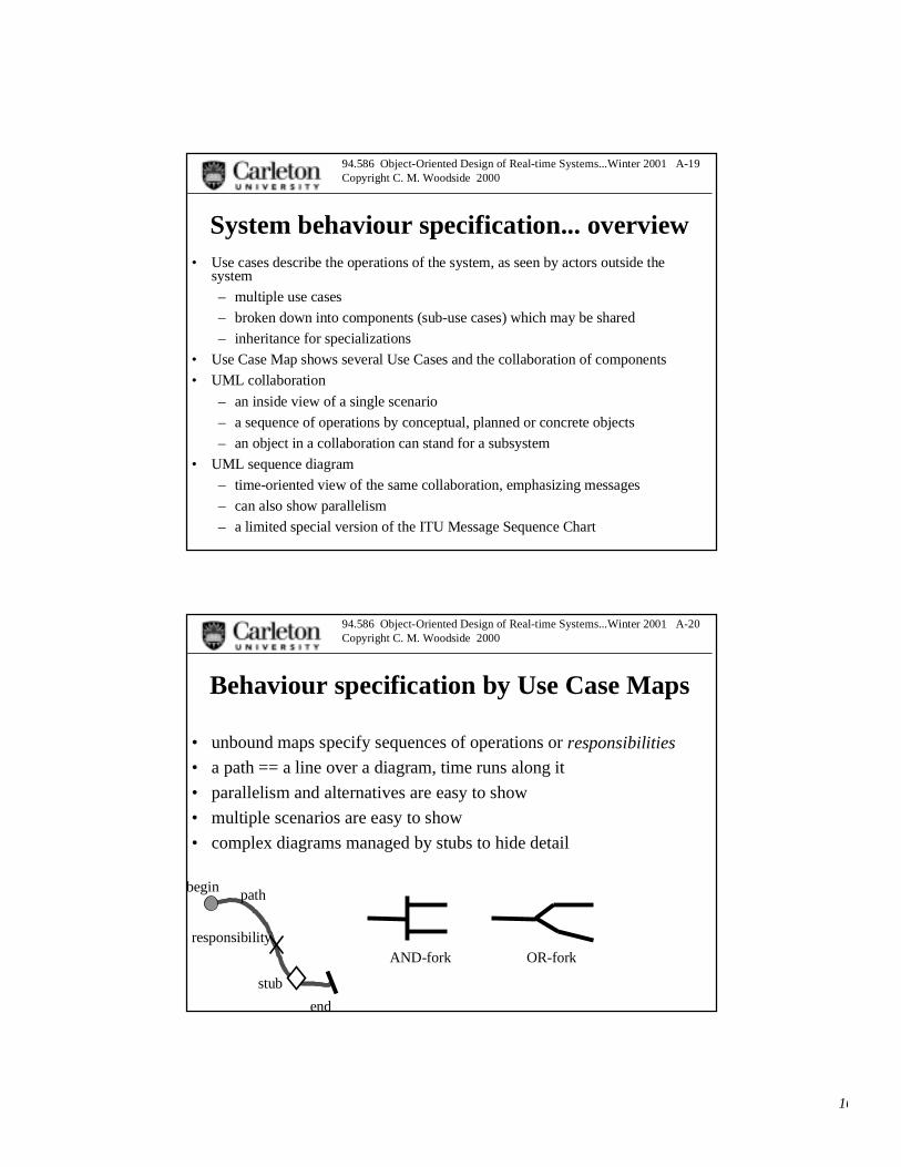
Behaviour specification by Use Case Maps
• unbound maps specify sequences of operations or responsibilities
• a path == a line over a diagram, time runs along it
• parallelism and alternatives are easy to show
• multiple scenarios are easy to show
• complex diagrams managed by stubs to hide detail
begin
end
path
responsibility
stub
AND-fork OR-fork

11
94.586 Object-Oriented Design of Real-time Systems...Winter 2001 A-21Copyright C. M. Woodside 2000
Complex UCM example
• groupcommuni-cationssystem
recMsg
getDocInf
getDocInf
getDocInf
getDocInf
newDI subLstAdd
bind
readFromD2
readFromD1
writeToD2
writeToD1
writeToD1
writeToD2
sendFile
sendAck
sendAck
sendNot
getSub
getDistLst
prepMsg
sendAck
sendAck
addSub
remSub
readFromCache
Tarr
Tget
Tnew
readFromCache
Tsub
Tuns
Tupd
Tnot
msgArr
main
writeF
sendNot
docInfo
docMap
D1Files
D2Files
recFile
94.586 Object-Oriented Design of Real-time Systems...Winter 2001 A-22Copyright C. M. Woodside 2000
Component behaviour specification
• UCM breaks into fragments or sub-maps or factors, within a singlecomponent
– may be multiple Use Case Map fragments
• module behaviour is specified by a state machine
– UML StateChart, or SDL state machine
GUI
Server
parse request
generate display
retrieve
x-in
y-out
req-z
z-out
GUI
req-z
z-out
parse request
generate display
12
94.586 Object-Oriented Design of Real-time Systems...Winter 2001 A-23Copyright C. M. Woodside 2000
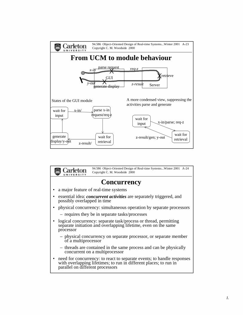
From UCM to module behaviour
wait forinput
GUI
Server
parse request
generate display
retrieve
x-in
y-out
req-z
z-result
parse x-inrequest/req-z
generatedisplay/y-out
wait forretrieval
x-in/
z-result/
States of the GUI module
wait forinput
wait forretrieval
x-in/parse; req-z
z-result/gen; y-out
A more condensed view, suppressing theactivities parse and generate
94.586 Object-Oriented Design of Real-time Systems...Winter 2001 A-24Copyright C. M. Woodside 2000
Concurrency• a major feature of real-time systems
• essential idea: concurrent activities are separately triggered, andpossibly overlapped in time
• physical concurrency: simultaneous operation by separate processors
– requires they be in separate tasks/processes
• logical concurrency: separate task/process or thread, permittingseparate initiation and overlapping lifetime, even on the sameprocessor
– physical concurrency on separate processor, or separate memberof a multiprocessor
– threads are contained in the same process and can be physicallyconcurrent on a multiprocessor
• need for concurrency: to react to separate events; to handle responseswith overlapping lifetimes; to run in different places; to run inparallel on different processors
13
94.586 Object-Oriented Design of Real-time Systems...Winter 2001 A-25Copyright C. M. Woodside 2000
The path of development (Gomaa)
• Use case development
• static modeling of the domain of the application
• design objects of various types
• scenario analysis to state machines, for behaviour
• architecture as clustering of objects into subsystems
– revised static model for data
– and as concurrency
• in this course, we consider behaviour and architecture together
– with enhanced scenario analysis via UCMs
– capability to experiment with, or analyse, concurrency issues
94.586 Object-Oriented Design of Real-time Systems...Winter 2001 A-26Copyright C. M. Woodside 2000
Going over the design steps in UML(1) Use Cases
Gomaa’s bank example....
(1) ... use cases: fig 19.1... specification in words sec 7.6 or 19.2
– actors (users or external entities (sensor, I/O device))
– preconditions
– description in words as a numbered sequence of steps
– alternatives
– postconditions
• use cases describe external requirements
• a use case may include another, as in fig 19.1, Validate PIN
14
94.586 Object-Oriented Design of Real-time Systems...Winter 2001 A-27Copyright C. M. Woodside 2000
Steps... (2) static modeling(2)... static modeling of the domain by entities, modeled as classes
• classes for types of information entities
• properties as data with types
• associations:
– cardinality sec 8.1 p 140
– ass’n description and direction and attributes
• composition: an instance of X consists of certain numbers of Y and Z
• aggregation: a composition where numbers may change
• inheritance
composite(e.g. car)
wheels
body
cruiser
flagshipaggregate(e.g. fleet)
1
3..*
1
3..*
94.586 Object-Oriented Design of Real-time Systems...Winter 2001 A-28Copyright C. M. Woodside 2000
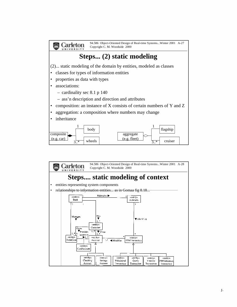
Steps.... static modeling of context• entities representing system components
• relationships to information entities... as in Gomaa fig 8.18...

15
94.586 Object-Oriented Design of Real-time Systems...Winter 2001 A-29Copyright C. M. Woodside 2000
Steps... (3) design objects• Gomaa introduces types of design objects fig 9.1
– interface• user, system, and device (in, out, in.out)
– entity, for data containers (and their operations)
– control, for program control logic
• timer, state dependent control, coordinator for hierarchy
– application logic, for pure computation
• business logic (less formal), algorithm (more formal)
control (coordinator)
control
input
entity-data
app. logic (processing) output
another control
94.586 Object-Oriented Design of Real-time Systems...Winter 2001 A-30Copyright C. M. Woodside 2000
Steps... design objects, from outside in
• fig 9.8, interface classes (bank card reader, receipt printer, user I/F,cash dispenser, operator I/F)
• entity classes (Account,
• control (ATM control of interfaces, fig 9.12)
• application logic (transaction mgrs for withdrawals, queries, transfers,PIN validation)
• coordinator of transactions
• packaging into subsystems
16
94.586 Object-Oriented Design of Real-time Systems...Winter 2001 A-31Copyright C. M. Woodside 2000
Steps... (4) scenarios to state-machines• create a collaboration (or several) for each use case (fig 11.3)
– design objects, numbered messages with arguments, conditions
– numbering scheme: 1st for the UC, point, sequence number, letterfor alternatives.
• optionally make a sequence diagram (e.g. fig 11.5)
• in state-dependent control objects, consider the flow of messages anddecisions and create a state machine to enforce the logic of the flow(fig 11.6).
• separate analysis of separate cases (fig 11.7, 8, 9)
....combined (fig 11.10)
• hierarchical state machine for abort (fig 11.11)
but: HOW DO WE KNOW WE HAVE A GOOD SET OFCONTROLLER OBJECTS? (we will use UCMs for this analysis)
94.586 Object-Oriented Design of Real-time Systems...Winter 2001 A-32Copyright C. M. Woodside 2000
Steps.... (5) architecture• this can be understood in different ways
– in Gomaa’s book, it is limited to clustering objects intosubsystems, so it comes after the “flat” design of the objects.
• subsystem level collaboration diagram fig 12.6 p 263
• Hofmeister/Soni/Nord describe an earlier and more prominent role:
– conceptual architecture is the first pass, something like Gomaa.However, it is considered to need revision, before being a design.
– module architecture is the second pass and fixes the modules andsubsystems.
• Control objects can be split and re-arranged, for instance.
– execution arch is the third phase and assigns processes/threadsand other concurrency factors,
– architecture of code is the final phase (file structure for code, forinstance)
17
94.586 Object-Oriented Design of Real-time Systems...Winter 2001 A-33Copyright C. M. Woodside 2000
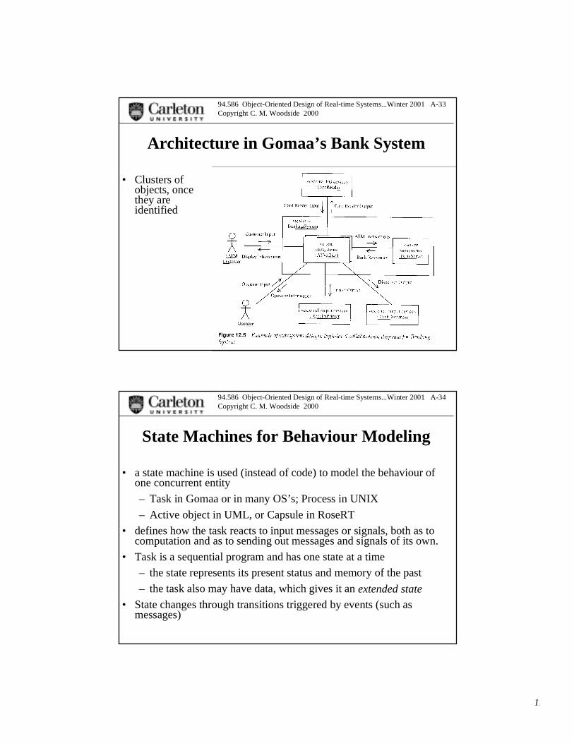
Architecture in Gomaa’s Bank System
• Clusters ofobjects, oncethey areidentified
94.586 Object-Oriented Design of Real-time Systems...Winter 2001 A-34Copyright C. M. Woodside 2000
State Machines for Behaviour Modeling
• a state machine is used (instead of code) to model the behaviour ofone concurrent entity
– Task in Gomaa or in many OS’s; Process in UNIX
– Active object in UML, or Capsule in RoseRT
• defines how the task reacts to input messages or signals, both as tocomputation and as to sending out messages and signals of its own.
• Task is a sequential program and has one state at a time
– the state represents its present status and memory of the past
– the task also may have data, which gives it an extended state
• State changes through transitions triggered by events (such asmessages)

18
94.586 Object-Oriented Design of Real-time Systems...Winter 2001 A-35Copyright C. M. Woodside 2000
Basic state machinestransition trigger can be: ... input message event (of a given type)
• input message type with guard condition on process data state and/ormessage data
• none (completion of a computation done while in the state)
action can be:... computation
• send a message type
(notice how a message type implies a port, which is a local view of thedestination of a message)
state may have an entry computation, body (do) computation, exit computation,internal trigger/action pairs, and deferred events (that are held back while in thisstate)
state1entry/actionexit/action
trigger/actiondo/activityevent/defer
state2input event [guard condition]/actionlist
initial state
final state
94.586 Object-Oriented Design of Real-time Systems...Winter 2001 A-36Copyright C. M. Woodside 2000
Basic state machines (2)• basic features are fairly conventional
– an object (capsule in RRT) is always in one state,
– a transition from a state may be triggered by receiving an event such as IN, orby completion of an activity executed in the state,
• these possibilities can’t be mixed
– one of several transitions may be triggered, selected by conditions
– in traversing the transition, a list of atomic actions may be executed...
IN [PIN valid]/ acknowledge, set timer, prompt user
state1IN [PIN valid]/
IN [PIN invalid]/state2
state3
19
94.586 Object-Oriented Design of Real-time Systems...Winter 2001 A-37Copyright C. M. Woodside 2000
examples
• look for...
– actions on transitions, on states, on entry or exit
– message sending actions (not obvious in first examples, as theyare for free-standing controllers that do not communicate)
– self-transitions
• think about
– termination (why not shown in first examples)
94.586 Object-Oriented Design of Real-time Systems...Winter 2001 A-38Copyright C. M. Woodside 2000
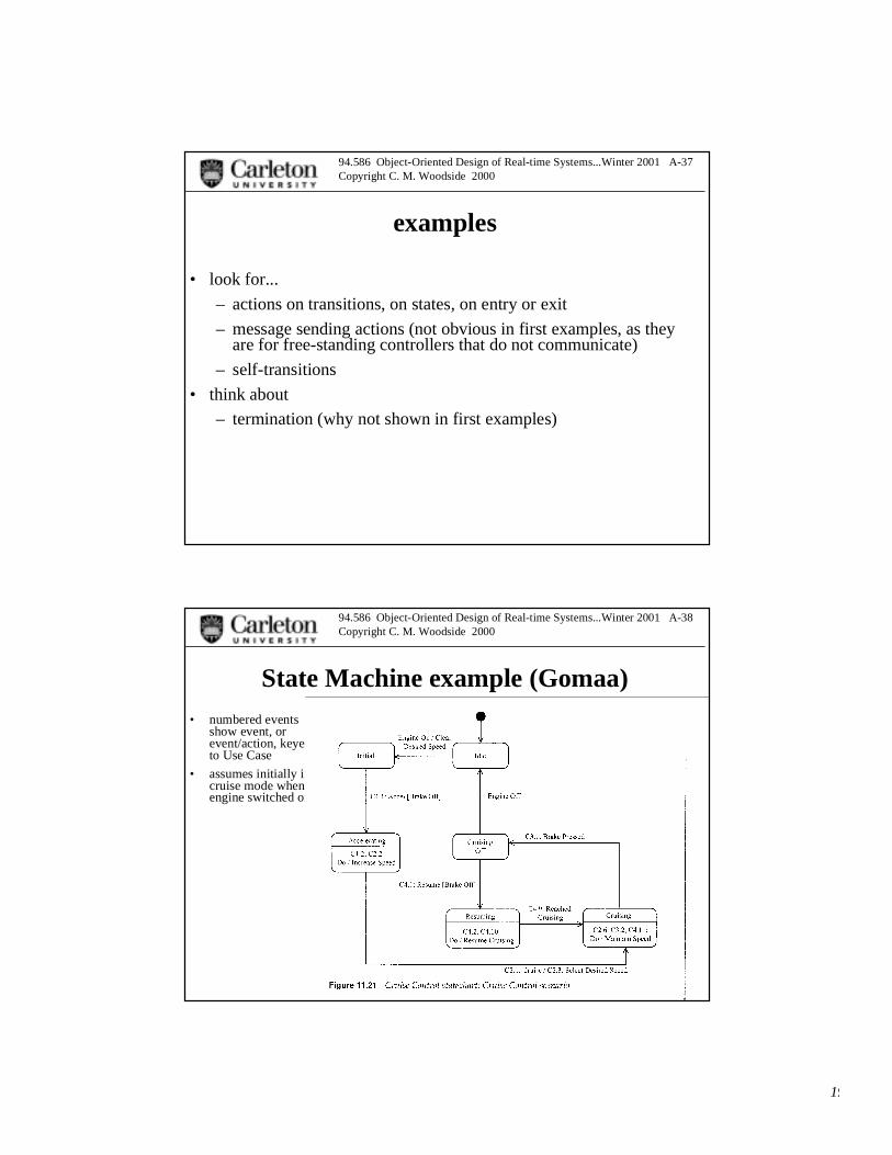
State Machine example (Gomaa)• numbered events
show event, orevent/action, keyedto Use Case
• assumes initially incruise mode whenengine switched on
20
94.586 Object-Oriented Design of Real-time Systems...Winter 2001 A-39Copyright C. M. Woodside 2000
more detailed version...
• including hierarchicalstates for transitionsout of automatedcontrol and enginerunning
94.586 Object-Oriented Design of Real-time Systems...Winter 2001 A-40Copyright C. M. Woodside 2000
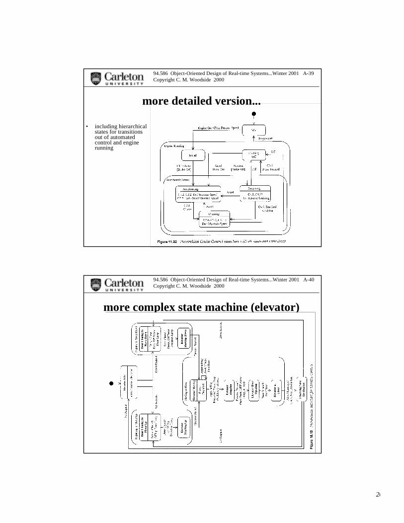
more complex state machine (elevator)
21
94.586 Object-Oriented Design of Real-time Systems...Winter 2001 A-41Copyright C. M. Woodside 2000
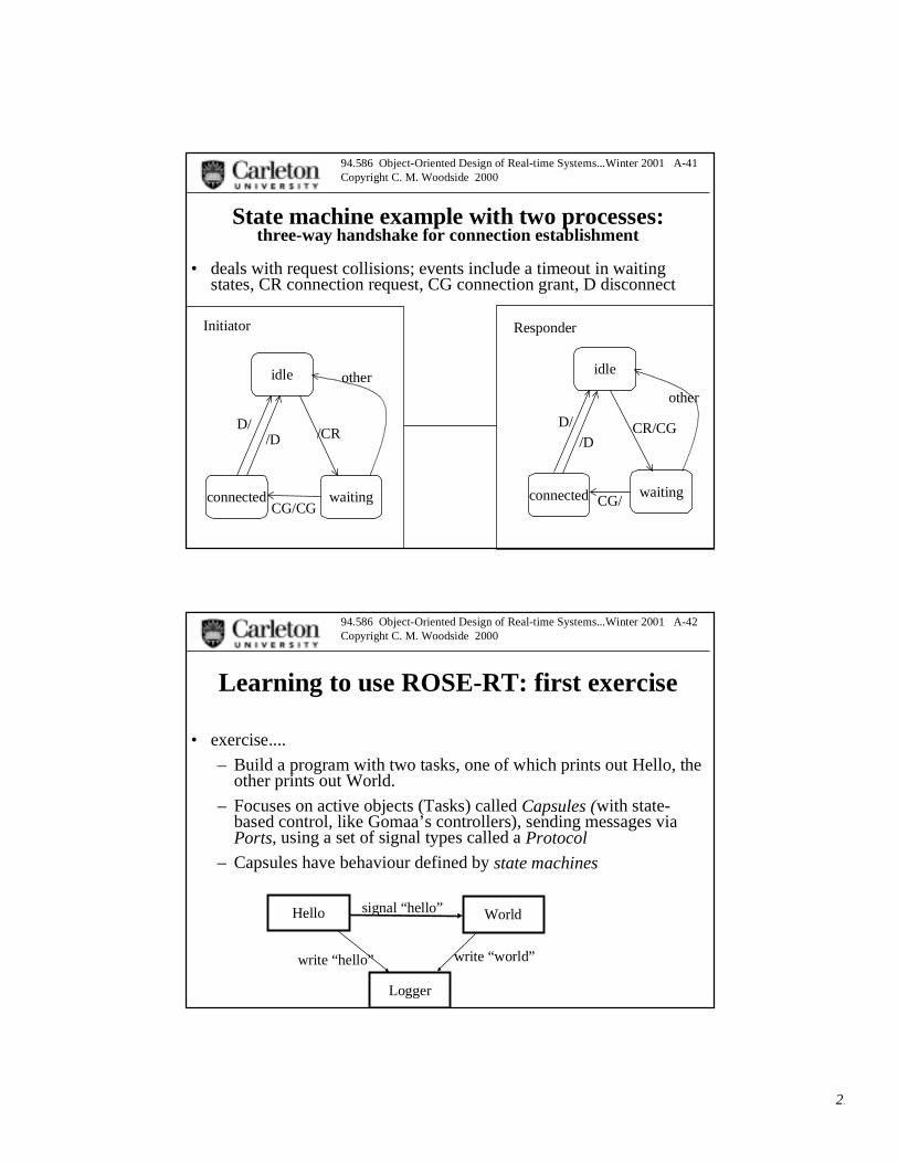
State machine example with two processes:three-way handshake for connection establishment
• deals with request collisions; events include a timeout in waitingstates, CR connection request, CG connection grant, D disconnect
idle idle
connected waiting waitingconnected
Initiator Responder
/CR
CG/CG
CR/CG
CG/
otherother
D/D//D /D
94.586 Object-Oriented Design of Real-time Systems...Winter 2001 A-42Copyright C. M. Woodside 2000
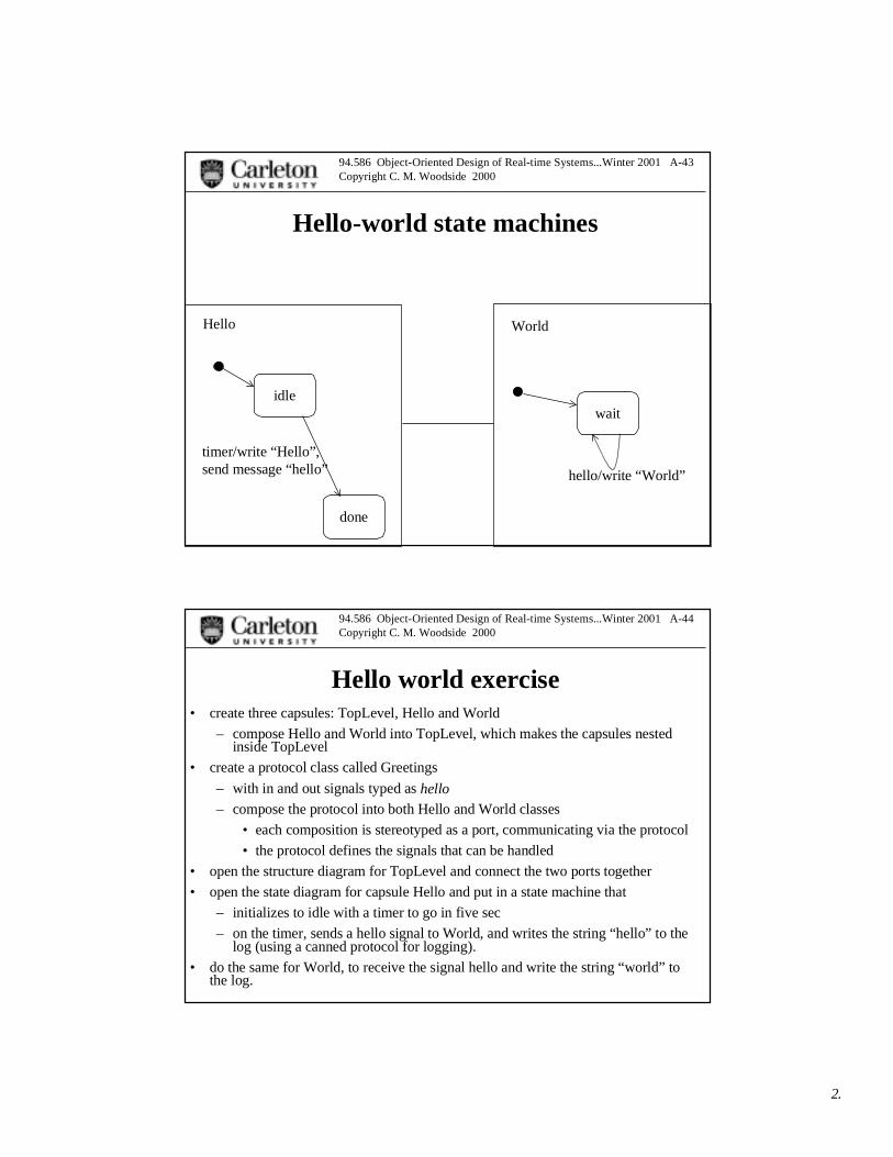
Learning to use ROSE-RT: first exercise
• exercise....
– Build a program with two tasks, one of which prints out Hello, theother prints out World.
– Focuses on active objects (Tasks) called Capsules (with state-based control, like Gomaa’s controllers), sending messages viaPorts, using a set of signal types called a Protocol
– Capsules have behaviour defined by state machines
Hello World
Logger
signal “hello”
write “world”write “hello”
22
94.586 Object-Oriented Design of Real-time Systems...Winter 2001 A-43Copyright C. M. Woodside 2000
Hello-world state machines
idlewait
done
Hello World
timer/write “Hello”,send message “hello” hello/write “World”
94.586 Object-Oriented Design of Real-time Systems...Winter 2001 A-44Copyright C. M. Woodside 2000
Hello world exercise• create three capsules: TopLevel, Hello and World
– compose Hello and World into TopLevel, which makes the capsules nestedinside TopLevel
• create a protocol class called Greetings
– with in and out signals typed as hello
– compose the protocol into both Hello and World classes
• each composition is stereotyped as a port, communicating via the protocol
• the protocol defines the signals that can be handled
• open the structure diagram for TopLevel and connect the two ports together
• open the state diagram for capsule Hello and put in a state machine that
– initializes to idle with a timer to go in five sec
– on the timer, sends a hello signal to World, and writes the string “hello” to thelog (using a canned protocol for logging).
• do the same for World, to receive the signal hello and write the string “world” tothe log.

23
94.586 Object-Oriented Design of Real-time Systems...Winter 2001 A-45Copyright C. M. Woodside 2000
RRRT Display of Structure UML Class view................... structure diagram view
Hellocapsule
Worldcapsule
TopLevel capsule
helloPort (two of them)employing the Greetingsprotocol with signal hello in and out
94.586 Object-Oriented Design of Real-time Systems...Winter 2001 A-46Copyright C. M. Woodside 2000
Build and run Hello-world
• build has a component wizard to create a component class with oneinstance, that will run in a simulated environment.
• run the single instance and see the output.

24
94.586 Object-Oriented Design of Real-time Systems...Winter 2001 A-47Copyright C. M. Woodside 2000
Heirarchical State machines• great contribution of David Harel, inventor of StateCharts
• a state can have substates (p 19 Fig 2.7):
– a transition to the state can go through into an inner state.
• RRT uses a junction point on the boundary of the outer state to carry thetransition from the outer to the inner diagram,
– or, when the outer state is reached it can activate an Initial state in the innermachine
• the object is in both the outer state, and one of the inner states
– some events are processed by the transitions in the inner machine, whichdescribe detailed behaviour
– such a transition can also leave the inner machine, to another state in the outermachine (normal completion)
– an event that causes a transition away from the outer state destroys the innerstate machine (abort)
• (some models retain the inner state as a HISTORY feature, and on nextentry go to it).
– nesting can proceed to any level
94.586 Object-Oriented Design of Real-time Systems...Winter 2001 A-48Copyright C. M. Woodside 2000
Hierarchical state machines (StateCharts)• adds the concept of substates:
– substates in an outer state: state = (outer state).(inner state)
• a transition to the outer state starts the inner state machine
(a) in its initial state, or
(b) in the state last occupied by the inner machine (“history”feature... the initial state is blank and labeled H)
• a transition away from the outer state (a) aborts or (b) pre-empts the inner state machine
– and a transition can go from an inner state directly to someother state outside... this also aborts the inner machine, butallows multiple next states to depend the inner state value.
– concurrent inner state machines, all active while in the inner state(AND machines). Models parallel operation of part of analgorithm.
25
94.586 Object-Oriented Design of Real-time Systems...Winter 2001 A-49Copyright C. M. Woodside 2000
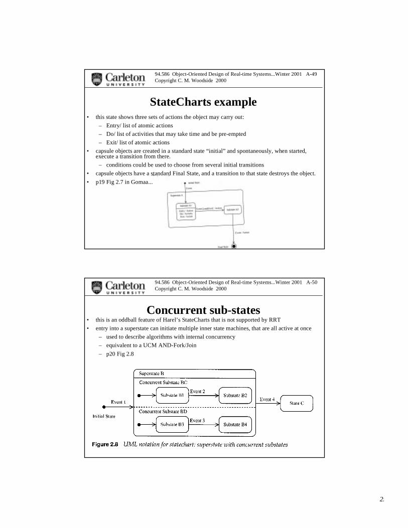
StateCharts example• this state shows three sets of actions the object may carry out:
– Entry/ list of atomic actions
– Do/ list of activities that may take time and be pre-empted
– Exit/ list of atomic actions
• capsule objects are created in a standard state “initial” and spontaneously, when started,execute a transition from there.
– conditions could be used to choose from several initial transitions
• capsule objects have a standard Final State, and a transition to that state destroys the object.
• p19 Fig 2.7 in Gomaa...
94.586 Object-Oriented Design of Real-time Systems...Winter 2001 A-50Copyright C. M. Woodside 2000
Concurrent sub-states• this is an oddball feature of Harel’s StateCharts that is not supported by RRT
• entry into a superstate can initiate multiple inner state machines, that are all active at once
– used to describe algorithms with internal concurrency
– equivalent to a UCM AND-Fork/Join
– p20 Fig 2.8

26
94.586 Object-Oriented Design of Real-time Systems...Winter 2001 A-51Copyright C. M. Woodside 2000
StateCharts example...
94.586 Object-Oriented Design of Real-time Systems...Winter 2001 A-52Copyright C. M. Woodside 2000
Thinking in state machines• a state machine can imitate a flow chart
– operations in states, decisions governing transitions
– states to wait for input
• send a prompt or request on entering the state, exit on arrival of input
– decisions as conditional transitions
• a machine with a single state is possible
– state waits for input
– different transitions from the state, depending on the signal type
– processing as an action on the transition, followed by sending output, and returnto the state.
• any kind of processing action can legally be defined on a transition,however the concept of action as atomic is more suitable for short actionsthan long ones that take time.
• for instance, an action on a transition cannot be interrupted or aborted byarrival of a signal.

27
94.586 Object-Oriented Design of Real-time Systems...Winter 2001 A-53Copyright C. M. Woodside 2000
Value of state-machine specification• Why state machines
– ... instead of flow charts, for instance
• heavily used in communications software
– protocols, call-processing
• introduced to support verification of logic of interacting processes
• the global state of a system is the vector (x, y, z...) of states of theindividual processes (state x of process 1, state y of process 2,...).
• as events are sent from one process and received at another, they arehandled by FIFO channels; global state includes the messages intransit.
94.586 Object-Oriented Design of Real-time Systems...Winter 2001 A-54Copyright C. M. Woodside 2000
Correctness analysis of state machines
• as messages are sent and received:
– ... the global state changes can be constructed, this is calledreachability analysis.
• State explosion limits the usefulness of this approach.
• also, asynchronous message sending can lead to unboundedchannel contents
• the global state machine can be analyzed to see if it
– is guaranteed to reach a terminal state, or
– has a deadlock.
– well-known tool PROMELA does this, for instance
• state machines give some practical clarity to complex sequences
– spaghetti code lives on as state machines.... intentional
28
94.586 Object-Oriented Design of Real-time Systems...Winter 2001 A-55Copyright C. M. Woodside 2000
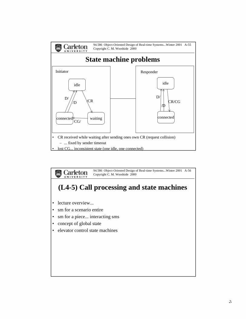
State machine problems
• CR received while waiting after sending ones own CR (request collision)
– ... fixed by sender timeout
• lost CG... inconsistent state (one idle, one connected)
idle idle
connected waiting connected
Initiator Responder
/CR
CG/
CR/CGD/D/
/D/D
94.586 Object-Oriented Design of Real-time Systems...Winter 2001 A-56Copyright C. M. Woodside 2000
(L4-5) Call processing and state machines
• lecture overview...
• sm for a scenario entire
• sm for a piece... interacting sms
• concept of global state
• elevator control state machines
29
94.586 Object-Oriented Design of Real-time Systems...Winter 2001 A-57Copyright C. M. Woodside 2000
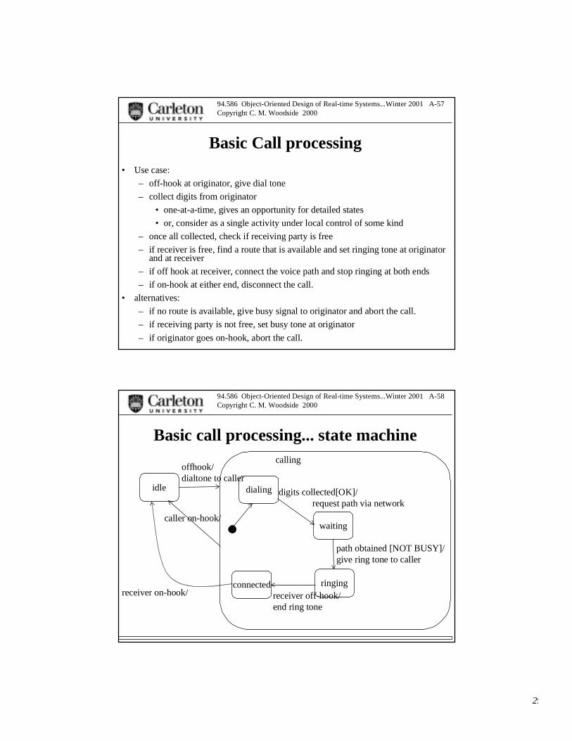
Basic Call processing
• Use case:
– off-hook at originator, give dial tone
– collect digits from originator
• one-at-a-time, gives an opportunity for detailed states
• or, consider as a single activity under local control of some kind
– once all collected, check if receiving party is free
– if receiver is free, find a route that is available and set ringing tone at originatorand at receiver
– if off hook at receiver, connect the voice path and stop ringing at both ends
– if on-hook at either end, disconnect the call.
• alternatives:
– if no route is available, give busy signal to originator and abort the call.
– if receiving party is not free, set busy tone at originator
– if originator goes on-hook, abort the call.
94.586 Object-Oriented Design of Real-time Systems...Winter 2001 A-58Copyright C. M. Woodside 2000
Basic call processing... state machine
idle dialing
waiting
ringingconnected
offhook/dialtone to caller
digits collected[OK]/request path via network
path obtained [NOT BUSY]/give ring tone to caller
receiver off-hook/end ring tone
receiver on-hook/
caller on-hook/
calling

30
94.586 Object-Oriented Design of Real-time Systems...Winter 2001 A-59Copyright C. M. Woodside 2000
Call processing... more conditions
idle dialing
waiting
ringingconnected
offhook/dialtone to caller
number collected[OK]/request path
path obtained [NOT BUSY]/give ring tone to caller
receiver off-hook/end ring tone
receiver on-hook/
caller on-hook/
callingwait foron-hook
loudtone
parked
digits [NOTOK]/give message “dial again”
TO/give loud tone
TO/
receiver busy orpath not available/give busy tone to caller
94.586 Object-Oriented Design of Real-time Systems...Winter 2001 A-60Copyright C. M. Woodside 2000
Modeling• call object, with originator, receiver, route
• originator terminal interface object, and terminal device
– interface object sets dial/ring/busy tones and collects digits
• originator control object, receiver control object
– messages on-hook, off-hook, dialed-number from terminalinterface objects to control
– messages set-dial-tone, set-ring-tone, set-busy-tone, and reset etc,to interface objects
– messages connect-req, on-hook from orig to recvr
– busy, not-busy, off-hook, on-hook from recvr to orig
– message find-route from orig to network, with return messagesroute-found(route) or no-route
• receiver terminal interface object and terminal device
31
94.586 Object-Oriented Design of Real-time Systems...Winter 2001 A-61Copyright C. M. Woodside 2000
Call processing sequence
• fig XXXX
94.586 Object-Oriented Design of Real-time Systems...Winter 2001 A-62Copyright C. M. Woodside 2000
Call processing state-machines
• orig, recvr XXXX
32
94.586 Object-Oriented Design of Real-time Systems...Winter 2001 A-63Copyright C. M. Woodside 2000
second RRT exercise (L4)
• simplified call processing model (call model #1)
– hardwired terminals, one to originate, one to receive
– off-hook, ring, off-hook, talk, on-hook, buzz remaining terminal,on-hook
– model the terminal interfaces and the control processes.
• inject events for terminal off-hook and on-hook, through a test port
– inject the events through a probe at each end
94.586 Object-Oriented Design of Real-time Systems...Winter 2001 A-64Copyright C. M. Woodside 2000
(L6) Some typical behaviour definitions
• SMs to go with pipelines, client-server, single independent tasks.
• simple cases
• Asst 1.
33
94.586 Object-Oriented Design of Real-time Systems...Winter 2001 A-65Copyright C. M. Woodside 2000
(L7-8-9) Developing an architecture
• outline of the problem
• important role of scenarios
94.586 Object-Oriented Design of Real-time Systems...Winter 2001 A-66Copyright C. M. Woodside 2000
UCMs for scenarios
• semantics of the UCM model
• reasoning about UCMs
• Navigator tool
34
94.586 Object-Oriented Design of Real-time Systems...Winter 2001 A-67Copyright C. M. Woodside 2000
Developing the architecture
• using UCMs
• Hofmeister styles and issues
• criteria for concurrency and for modularity
• Craig example
94.586 Object-Oriented Design of Real-time Systems...Winter 2001 A-68Copyright C. M. Woodside 2000
(L10-11-12) Hierarchical systems
• more complex cases from L6
• multiple controller systems
– controller and workers (elevator)
• client-server (e-commerce
• callback interactions
• getting there from UCMs with multiple fragments in a task
• router example
• elevator

35
94.586 Object-Oriented Design of Real-time Systems...Winter 2001 A-69Copyright C. M. Woodside 2000
(L12-13) Pipelines
• signal processing?
94.586 Object-Oriented Design of Real-time Systems...Winter 2001 A-70Copyright C. M. Woodside 2000
Call processing pipeline (DFC)
36
94.586 Object-Oriented Design of Real-time Systems...Winter 2001 A-71Copyright C. M. Woodside 2000
(L14) Peer interaction systems (e-commerce)
• async interaction
94.586 Object-Oriented Design of Real-time Systems...Winter 2001 A-72Copyright C. M. Woodside 2000
(L15) Layered arch
• layer as a service layer, abstraction
37
94.586 Object-Oriented Design of Real-time Systems...Winter 2001 A-73Copyright C. M. Woodside 2000
(L16-17) Control systems
94.586 Object-Oriented Design of Real-time Systems...Winter 2001 A-74Copyright C. M. Woodside 2000
Issues