oasis heating system installation and operating...
TRANSCRIPT
OASIS®Heating System
Installation and
Operating Manual
Diesel and AC Heating System
for Recreational Vehicles and Yachts
CSA TIL R-17
ANSI/UL307A
CAN/CSA-C22.2 No.165
Copyright © January 2011, Revised August 2016
International Thermal Research
IN CANADA: IN THE UNITED STATES:
2431 Simpson Road 5305 NE 126th Ave, Suite 401
Richmond, BC, Canada V6X 2R2 Vancouver, WA, USA 98682
Tel: 1-800-755-1272 or 604-278-1272 Tel: 1-800-993-4402 or 360-993-4877
Fax: 604-278-1274 Fax: 360-993-1105
Email: [email protected]
Website: http://www.itrheat.com
All rights reserved. No part of this manual may be reproduced or
transmitted in any form by any means, electronic or mechanical, including photocopying and recording, information storage,
retrieval, or transmission, without permission in writing from
International Thermal Research
Right to Modify:
Due to our commitment for quality and ongoing product improvement, ITR reserves the right to modify or change
without notice, any materials, applications, equipment, accessories, and/or prices. All measurements and weights are
approximate.
International Thermal Research iii
Table of Contents
Section 1, Overview...................................................1-1
1.1 Unpacking the Heating Module ....................... 1-2
1.2 Protect Your Warranty ................................... 1-2 1.3 Oasis™ Heating Module Features .................... 1-3 1.4 Critical Factors ............................................. 1-5
1.5 Equipment, Tools and Skills ........................... 1-6 1.6 Testing and Inspection .................................. 1-7
Section 2, Mounting the Oasis™ Heating Module .......2-1
2.1 Before You Begin .......................................... 2-1 2.2 Identifying Your Oasis™ Heating Module Model. 2-2 2.3 Your Mounting Location ................................. 2-2
2.4 What NOT to Do ........................................... 2-4 2.5 Procedure .................................................... 2-4
Section 3, Installing the Exhaust System...................3-1
3.1 Before You Begin .......................................... 3-1
3.2 Mounting Location......................................... 3-1 Recommended Exhaust Outlet Locations.............3-1
Recommendation for Installation .......................3-2
What NOT to Do ..............................................3-4
3.3 Procedure .................................................... 3-4
Section 4, Installing the Fuel System.........................4-1
4.1 Before You Begin .......................................... 4-1
4.2 Fuel System Operation .................................. 4-1 Recommendations for Installation......................4-1
4.3 What NOT to Do ........................................... 4-2
4.4 Procedure .................................................... 4-3
Section 5, Installing Fan Heaters...............................5-1
5.1 Before You Begin .......................................... 5-1
Table of Contents
iv Installation and Operating Manual for OASIS Heating Module™
5.2 Fan System Operation ...................................5-2 Features.........................................................5-2
Multiple Zone Heating ......................................5-3
Accessories and Components Needed.................5-3
5.3 What NOT to Do............................................5-4
5.4 Mounting Locations........................................5-4 5.5 Procedure.....................................................5-5
Section 6, Wiring the Electrical System..................... 6-1
6.1 Before You Begin...........................................6-1
6.2 12 VDC ........................................................6-1 6.3 120 VAC.......................................................6-2 6.4 Remote Operating Panel Cable ........................6-2
6.5 Main Electronic Control Board .........................6-3 6.6 Distribution Module Zone Control Board
(Optional) ....................................................6-3 6.7 What NOT to Do............................................6-4
Section 7, Plumbing the System................................ 7-1
7.1 Before You Begin...........................................7-1
7.2 Plumbing Installation .....................................7-1 7.3 What NOT to Do............................................7-4
7.4 Installation Procedure ....................................7-4
Section 8, Operating the Oasis™ Heating Module ...... 8-1
8.1 Features of your Oasis™ Heating Module..........8-1 8.2 Your Heating Module Model ............................8-2
8.3 Operating Instructions for the Oasis™ Heating Module..................................8-3 8.4 Turning the Power to the
Oasis™ Heating Module ON ............................8-4 8.5 Activating the Burner (Primary)
and AC Heat (Secondary) from the Remote Operating Panel.................................8-5 8.6 Activating the Cabin Fan Heaters
through the Thermostats................................8-6 8.7 Activating the Domestic Hot Water ..................8-6
8.8 Activating the Engine Heat .............................8-6 8.9 Functions of the Remote Operating Panel .........8-7 8.10 Functions of the Heating Module Control Panel ..8-9
Table of Contents
International Thermal Research v
8.11 Functions of the Distribution Module (Optional)
Zone Control Panel ......................................8-10 8.12 Maintenance ...............................................8-11
8.13 Protecting the Heating Module and Distribution Module (Optional) .......................8-13 8.14 General Troubleshooting...............................8-13
Section 9, Installing Distribution Module, DM-12 (optional) ..................................................................9-1
9.1 Installing your Distribution Module (optional) ... 9-1 9.2 Selecting the Module Location ........................ 9-1
9.3 Selecting the Distribution Module Zone Box Location ........................................ 9-2
9.4 Plumbing Installation..................................... 9-3 9.5 Filling/Purging the heating loop ...................... 9-7 9.6 Electrical Connection ..................................... 9-8
9.7 Distribution Module Zone Control Board........... 9-9 9.8 Inspection and Testing .................................9-12
9.9 Hot water temperature adjustment ................9-12
Warranty Information & Warranty Card

Table of Contents
vi Installation and Operating Manual for OASIS Heating Module™
List of Figures
Figure 1-1 Oasis™ Module .........................................1-1 Figure 1-2 Oasis™ Heating and Distribution Module ......1-5
Figure 2-1 Module Dimensions ...................................2-3
Figure 2-2 Module Mounting Brackets .........................2-5 Figure 3-1 Installing the Exhaust System
(Bottom Exhaust) .....................................3-6 Figure 3-2 The Exhaust Hole Location & Mounting
Template .................................................3-6 Figure 3-7 The Exhaust Goose neck Configuration ........3-7
Figure 5-1 Wiring the Fan’s Aquastat ..........................5-2 Figure 5-2 Mounting a Spacesaver Fan........................5-6
Figure 5-3 Installing a Relay for Add’l Fan Amperage ....5-6
Figure 6-1 System Wiring..........................................6-3
Figure 7-1 Heating Module ........................................7-3 Figure 7-2 Three Approved Methods of Installing
Heater Hose (consult ITR for alternative methods and products)..............................7-5
Figure 8-1 Oasis™ Heating Module .............................8-3 Figure 8-2 Heating Module Main Control Panel .............8-4
Figure 8-3 Remote Operating Panel ............................8-7 Figure 8-4 Zone Control Panel ................................. 8-11
Figure 9-1 Distribution Module ...................................9-2
Figure 9-2 Distribution Module Zone box .....................9-2 Figure 9-3 Distribution Module Fittings Location ...........9-3 Figure 9-4 Domestic Hot Water System Plumbing.........9-4
Figure 9-5 Engine Heat / Pre-heat System Plumbing.....9-5 Figure 9-6 Connecting to the OASIS Heating Module.....9-5
Figure 9-7 Connecting two Heating loops ....................9-6 Figure 9-8 Initial fill up Oasis system..........................9-7 Figure 9-9 Distribution Module Wiring ....................... 9-10
Figure 9-10 Zone Board Wiring (No Distribution module) . 9-11 Figure 9-11 Mixing valve location............................... 9-12
International Thermal Research 1-1
Overview
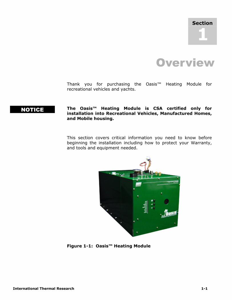
Thank you for purchasing the Oasis™ Heating Module for recreational vehicles and yachts.
The Oasis™ Heating Module is CSA certified only for installation into Recreational Vehicles, Manufactured Homes,
and Mobile housing.
This section covers critical information you need to know before
beginning the installation including how to protect your Warranty, and tools and equipment needed.
Figure 1-1: Oasis™ Heating Module
Section
1
NOTICE

Section 1, Overview
1-2 The Oasis™ Heating Module
1.1 Unpacking the Oasis™ Heating Module
When you receive the Oasis™ Heating Module:
1 Unpack it carefully.
2 Check each component against the shipping list to ensure that you have everything and that all parts arrived undamaged.
3 If you discover any missing or defective parts call ITR immediately.
4 If you are not installing the Oasis™ Heating Module right away secure all components so none will be misplaced.
5 Before installing the Oasis™ Heating Module read the rest
of this Installation and Operating Manual. It containscritical information for a proper installation.
A properly installed Oasis™ Heating Module is essential for several reasons:
• To ensure that you and/or your customers receive satisfactory
results and enjoy a warm, comfortable environment.
• To ensure a trouble-free installation, a successful inspection and
testing process, and ease of future maintenance.
• To protect your Warranty.
1.2 Protect Your Warranty
This document reflects approved installation techniques, methods,
and materials, and applies only to ITR equipment. The Oasis™ Heating Module is only guaranteed by ITR if the entire system has
been installed according to the requirements and recommendations set out here.
This includes:
• Deviations from the instructions in this Manual. • Changes to any piece of ITR-supplied equipment.
• Substitution of a non-ITR approved component.
No Warranty will be extended to improper installations. Use of any
unapproved materials, equipment or installation procedures will
Section 1, Overview
International Thermal Research 1-3
result in a voided warranty for the entire heating system. Any loss of service or damage as a result of any unapproved modification is
the responsibility of the installer. ITR accepts no liability for any damage or loss of service resulting from unapproved modifications.
1.3 Oasis™ Heating Module Features
The Oasis™ Heating Module uses a diesel burner (12 VDC) controlled by a multi-functional electronic controller as the primary
source of heating coolant fluid (anti-freeze and water). Two 1500 Watt, 120 VAC immersion elements are used as secondary heat
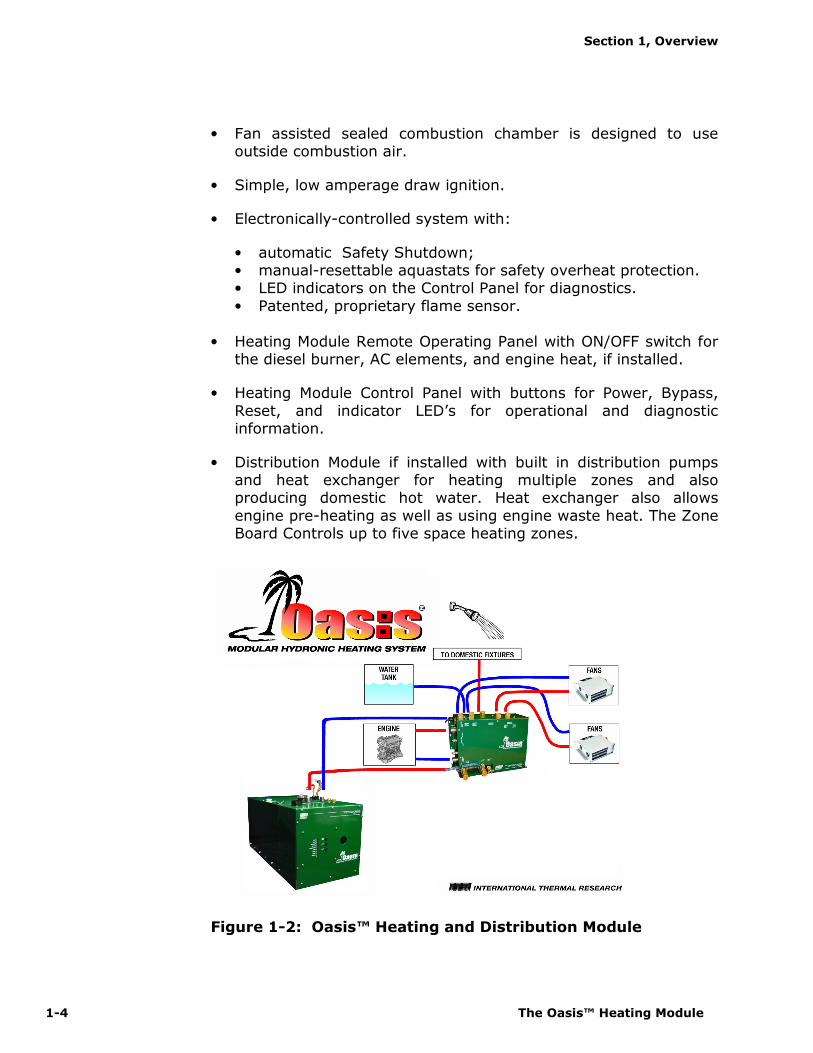
sources. The Oasis™ Heating Module heats the coolant fluid to provide a source of heat for all hydronic space heating needs. When used with the Distribution Module (optional) and its integral
distribution pumps, the Oasis™ Heating Module has the ability to circulate the coolant fluid to all space heating areas. It can also
provide a supply of domestic hot water using the integral heat exchanger in the Distribution Module. The Oasis™ also incorporates
engine heat and preheat functions. (see Figure 1-2: Oasis™
Heating and Distribution Modules).
Other features of the Oasis™ Heating Module include:
• A high-temperature, stainless steel burner and stainless steel jacket.
• 9.5 US gallon welded, insulated stainless steel coolant tank that minimizes heat loss and optimizes heat recovery.
• Low coolant level switch on the tank.
• Easy to install, completely modular and field serviceable with the Oasis™ Heating Module hookups and connections easily
accessible from the front and top of the Heating Module.
• Quiet operation and low power consumption.
• Low pressure fuel system with built-in fuel pump.
• Fuel efficient burner capable of burning a wide variety of diesel-based fuels.
• Exhaust has minimal smoke and smell.
• Efficient
• Clean
• Quiet
• Compact
• Safe
• Rugged
• Reliable • Economical
Section 1, Overview
1-4 The Oasis™ Heating Module
• Fan assisted sealed combustion chamber is designed to use outside combustion air.
• Simple, low amperage draw ignition.
• Electronically-controlled system with:
• automatic Safety Shutdown; • manual-resettable aquastats for safety overheat protection. • LED indicators on the Control Panel for diagnostics.
• Patented, proprietary flame sensor.
• Heating Module Remote Operating Panel with ON/OFF switch for the diesel burner, AC elements, and engine heat, if installed.
• Heating Module Control Panel with buttons for Power, Bypass,
Reset, and indicator LED’s for operational and diagnostic information.
• Distribution Module if installed with built in distribution pumps and heat exchanger for heating multiple zones and also producing domestic hot water. Heat exchanger also allows
engine pre-heating as well as using engine waste heat. The Zone Board Controls up to five space heating zones.
Figure 1-2: Oasis™ Heating and Distribution Module

Section 1, Overview
International Thermal Research 1-5
1.4 Critical Factors
THE INSTALLATION SHALL BE IN ACCORDANCE WITH THE REGULATIONS OF AUTHORITIES HAVING JURISDICTION
The key factors to keep in mind when planning and carrying out the installation are:
• Mounting location restrictions for the Oasis™ Heating Module, optional Distribution Module , and exhaust outlet (to reduce noise, vibration, heat loss, etc.).
• Length, routing and sizing of fluid lines, fuel lines, air-flow tubing, exhaust piping and wiring.
• Unrestricted vent required to draw in 100% outside air for combustion.
• Ability for technician to easily access and service the product,
especially fuel, plumbing, and electrical systems.
• After installation, ability to purge water and fuel lines and
inspect/test entire system using the ITR-supplied Inspection Check Sheet.
1.5 Equipment, Tools and Skills
As the user and/or installer, you must be qualified and authorized to do the installation, which requires mechanical aptitude and electrical knowledge. Make sure you comply with existing RVIA or ABYC
industry practices, using the highest and most recent standards and codes. Good workmanship is essential. Please refer back to
Section 1 – Overview, sub-Section 1.2, Protect Your Warranty.
You will need the following equipment and tools to install the heating system (not supplied). This list does not include optional
equipment and accessories:
• Standard tools normally available in a well-equipped shop.
• Approved fasteners for mounting the heater unit.
• Steel (or stainless steel) 2” ID exhaust system piping, maximum 12’ with no bends. (See Section 3 – Installing the Exhaust
System, for details when bend are present.).
Pay attention to the
notices of “Danger”
“Warning” “Caution”
and “Notice” in this manual.

Section 1, Overview
1-6 The Oasis™ Heating Module
• Exhaust collar.
• ITR-muffler with straight-through design.
• 1/4” supply fuel line, approved rubber or copper.
• #10 sheet metal screws or wood screws to mount fan units
inside the occupied areas.
• Heater hose (to connect optional Distribution Module hose fittings to interior fans).
• Domestic water hose and/or tubing to connect the Distribution Module hose fittings to the domestic water system.
• Overflow tank to connect to the Oasis™ Heating Module with clear plastic 3/8” hose; tank must be heavy-duty plastic, with a screw-down cap, and sturdy enough to mount firmly to a vertical
surface.
• Up to five (5) thermostats (DC compatible) to allow temperature
regulation of the heating zones when connected to the Distribution Module.
1.6 Testing and Inspection
After all components have been properly installed according to standard practices, RVIA or ABYC standards, and the recommendations of this Installation and Operating Manual, the
Oasis™ Heating Module should be test-operated for inspection purposes.
For your convenience, you can use the pullout Inspection Check
Sheet in this Manual. The Inspection Check Sheet is divided into progressive sections, allowing each phase of the inspection to be
carried out systematically, and then signed off by authorized persons.

Section 1, Overview
International Thermal Research 1-7
International Thermal Research 2-1
Mounting – Oasis™ Heating
Module
2.1 Before You Begin
Plan the location of the Oasis™ Heating Module and all its major components in advance to ensure the chosen locations are compatible with installation requirements and within the technical
specifications.
Consider the following factors to help you decide exactly where
best to mount the Oasis™ Heating Module:
• Oasis™ Heating Module weight when full (160 lbs).
• Ventilation requirements.
• Exhaust outlet location and maximum acceptable length.
• Thru hull location and waterline (yachts).
• Potential for vibration and jarring.
• Length of run from fuel source to heater.
• Most efficient plumbing runs.
• Safe and convenient access for maintenance.
• Number and location of interior fans.
• Location of other equipment to be installed or connected to the Oasis™ Heating Module, including the optional Distribution Module, Zone Control Box, heat exchangers,
overflow tank, batteries, etc.
Section
2

Section 2, Mounting the Oasis™ Heating Module
2-2 The Oasis™ Heating Module
Make sure you are familiar with Section 1 – Overview of this
Manual. If the system is not installed according to specifications
and with the correct equipment, your Oasis™ Heating Module may not operate properly, safety may be compromised, and your
Warranty may be voided.
2.2 Identifying Your Oasis™ Heating
Module Model
As the owner, you must be fully aware of the controls and
operating features particular to your model of the Oasis™ Heating Module. This is essential for the proper functioning and life of your
Oasis™ Heating Module as well as protecting your warranty. Your model can be identified by locating the serial number label on the
outside case of the Oasis™ Heating Module. The serial number identifies the model type through the first series of letters and numbers.
The types of Oasis™ Heating Module models are:
CH50S – Oasis™ Heating Module (Stainless Steel Case)
CH50B – Oasis™ Heating Module (Galvanized Case)
2.3 Your Mounting Location
Your mounting location should consider the following:
• Mounting location must be able to support double the gross
weight of the Oasis™ Heating Module (i.e. 160 lbs. x 2 = 320lbs./73 KG x 2 = 146 KG) and must be of a non-
combustible and non absorptive surface.
• Oasis™ Heating Module is 14”H x 14”W x 30” D. (35.6 cm x 35.6 cm x 76.1 cm), see Figure 2-1: Module Dimensions.
• Oasis™ Heating Module must be installed in a compartment which is completely isolated from the atmosphere of living
spaces.
• Combustion air must be drawn from an outside source and cannot contain any combustible gases.
!!!! WARNING

Section 2, Mounting the Oasis™ Heating Module
International Thermal Research 2-3
• Oasis™ Heating Module must be mounted in an area that provides unrestricted access to the front panel. Allow space for
connection to the fuel and coolant lines, as well as the power and exhaust connections. (Minimum of 10” top clearance - top
exhaust version; minimum of 6” top clearance - bottom exhaust version; 0” clearance to all other Oasis™ Heating Module surfaces). Allow 1” clearance on the sides for attaching
the mounting brackets.
• Mount the unit with the front panel side facing out and
accessible. Facing out simplifies installation and maintenance.
• Oasis™ Heating Module must be mounted horizontal and level using eight, 1/4” through bolts and 1” diameter fender
washers, lock washers and nuts.
Figure 2-1: Module Dimensions
Oasis™ Heating Module must not be installed or operated in any
compartment with flammable gases.
If the Oasis™ Heating Module is going to be mounted in the engine compartment, check for adequate ventilation. When the engine is
running this area could be under a negative pressure. Make sure the air-intake and exhaust hoses have no leaks and are well
fastened to the heater, muffler and thru-hull fitting. Assembly parts that may cause injury through accidental contact should be protected.
! DANGER
! WARNING
Section 2, Mounting the Oasis™ Heating Module
2-4 The Oasis™ Heating Module
Isolate the unit in a closed compartment so that no air from the
heater will infiltrate the living areas.
• It is recommended that a catchpan be placed under the Oasis™
Heating Module for containing any unexpected leakage.
• Choose a sturdy surface in a location that won’t be unduly affected by vibration and the jarring of rough roads or rough
seas.
• Ensure that the exhaust tubing can be properly and safely
routed to the outside. The maximum exhaust run for the system is 12’.
2.4 What NOT to Do
• Don’t mount the Oasis™ Heating Module in the rear of the coach or yacht underneath the sleeping area. The sound of the
Oasis™ Heating Module cycling on and off may disturb light sleepers.
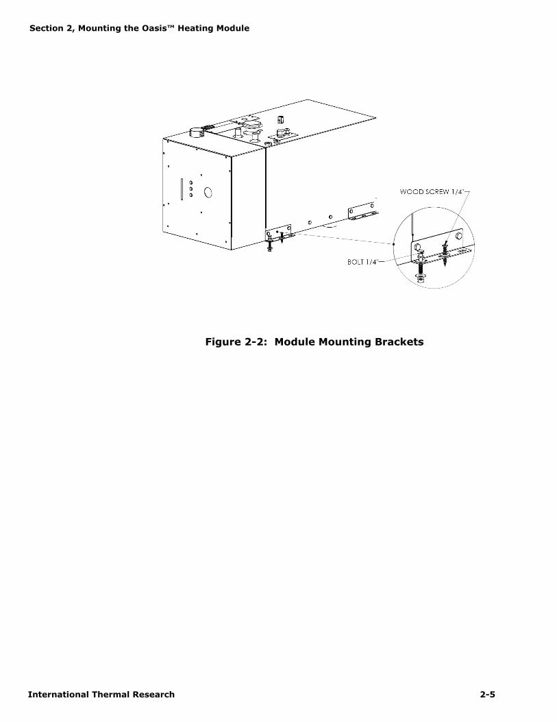
2.5 Procedure
After choosing the mounting location for the Oasis™ Heating
Module, mount the module horizontally and level. Secure the Oasis™ Heating Module in place (against the wall, floor or a mounting platform) using eight (8) x 1/4” through bolts and 1”
diameter fender washers, lock washers, and nuts. (See Figure 2-2: Module Mounting Brackets.).
! DANGER
Section 2, Mounting the Oasis™ Heating Module
International Thermal Research 2-5
Figure 2-2: Module Mounting Brackets
Section 2, Mounting the Oasis™ Heating Module
2-6 The Oasis™ Heating Module
International Thermal Research 3-1
Installing the Exhaust System
3.1 Before You Begin
For efficient and safe operation of the Oasis™ Heating Module follow all recommendations for properly installing the exhaust. Any deviations from these must be approved in advance by ITR.
Although the heater’s exhaust produces very low carbon monoxide
emissions, caution is still advised:
• Do not operate the Oasis™ Heating Module in an enclosed area unless there is adequate ventilation.
• Isolate the Oasis™ Heating Module in a closed compartment so that no air from the unit will infiltrate the living areas.
Never place any exhaust parts close to combustible material or through a combustible wall or ceiling without fireproof protection.
The exhaust can reach high temperatures.
3.2 Mounting Location
If you can’t meet the technical specifications for mounting
the exhaust, don’t use the Oasis™ Heating Module. The unit may perform poorly or become damaged if not installed
according to specifications.
Recommended Exhaust Outlet Locations
The following is recommended for a coach exhaust outlet location:
• Mount the exhaust outlet outside the coach, not inside the
heater compartment. Otherwise, exhaust fumes could infiltrate the coach from the Oasis™ Heating Module.
Section
3
!!!! DANGER

Section 3, Installing the Exhaust System
3-2 The Oasis™ Heating Module
• When mounting the Oasis™ in a coach, the typical mounting location for the exhaust outlet is under the floor of the
Oasis™ compartment and out from the side of the coach, or out from the opposite side of the coach, directly across from
the heater. The Oasis™ CH50M will allow a maximum of 12’ of exhaust piping, without any bends (excluding the exit bend from the heater). The Oasis™ CH50MQ will allow a maximum
of 23’ of exhaust piping, without any bends (excluding the exit bend from the heater). You may use sweep bends but
each 90º bend is equivalent to two feet of exhaust piping. For example, when fitting the exhaust for a CH50M using two 90º bends, you must subtract two feet per bend from the
maximum allowed 12’ exhaust length. Therefore you will be restricted to 8’ of straight exhaust piping plus the two 90º
bends. Do not exceed these recommendations.
• Position the outlet of the exhaust pipe so that the exhaust exits out from the side of the coach, not directly underneath
the coach or under an opening window or vent.
• If the exhaust is mounted under a slide-out, the outlet of the
exhaust must be a minimum of 36” (inches) below the side-out including skirts and moldings.
In a yacht installation, the following is recommended for the exhaust outlet location:
• Mount the exhaust thru hull so that the exhaust fumes cannot enter or re-infiltrate any living areas.
• Make sure that the thru hull is at least 30” above the water
line with a goose neck rise on the exhaust to help eliminate
water from getting to the Oasis™ Heating Module through the exhaust. If the dual exhaust air-intake thru hull is used,
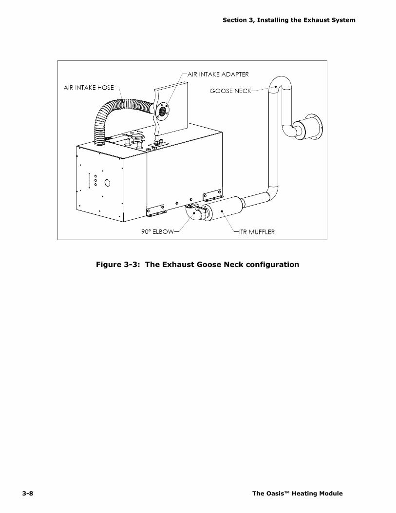
ensure that the air-intake is placed between 10 o’clock and 2 o’clock and also goose-necked to avoid water ingestion, see Figure 3-3: The Exhaust Goose Neck Configuration.
• There needs to be a 1/8" air gap around the exhaust thru hull.
The standard thru hull is 4" in diameter. The hole for the fitting should be 4-1/4". Make sure that the holes for the mounting screws have enough material left to properly bite.
The fitting must be centered in the hole.
Section 3, Installing the Exhaust System
International Thermal Research 3-3
Recommendation for Installation
The following applies to both a coach and yacht:
• You may use sweep bends but each 90° bend is equivalent to
two feet of exhaust piping. For example, if you use two 90° bends you must subtract two feet per bend from the
maximum allowed 12’ exhaust length. Therefore you will be restricted to 8’ of straight exhaust piping plus the two bends. Do not exceed these recommendations.
• The combustion air must be drawn from outside the coach or yacht. The maximum length of the air-intake tubing is 7 feet.
Do not exceed this recommendation.
• Use an ITR-manufactured muffler with a straight-through design. No other muffler is acceptable.
• Exhaust outlet is on the top or bottom (model dependant) of the Oasis™ Heating Module, towards the back.
The exhaust and outlet are HOT and the surrounding areas must be thermally shielded and protected from the hot
surfaces and heat build-up by insulation. Nothing can come into inadvertent contact with any part of the exhaust system.
• Exhaust must have a minimum of 3” (7.6 cm) clearance from all surfaces.
• Ensure that the exhaust cannot be plugged or restricted.
• The exhaust fitting on the Oasis™ Heating Module is 2.0” O.D. and the exhaust pipe used must have a minimum of
2.0” I.D. throughout its length.
• All exhaust elbows must be of a large radius design.
• The exhaust must be supported a minimum of every 3’ of its
installed length.
• The exhaust and Oasis™ Heating Module connection point
must use appropriate clamps and sealing compound to ensure that the connections are tight and leak free. The Oasis™
Heating Module exhaust outlet pipe and the exhaust pipe itself must not be distorted or damaged during this process.
! DANGER

Section 3, Installing the Exhaust System
3-4 The Oasis™ Heating Module
• When the Oasis™ Heating Module is running the connection points and the system must be checked for leaks and any
found must be corrected. Periodically, check the exhaust fittings, connections, exhaust tube, and insulation for leaks
and integrity and correct if required.
• Appropriate exhaust insulation must be used to cover the entire length of any interior exhaust run.
• Solid stainless steel exhaust tubing or approved exhaust tubing is recommended but an approved stainless steel
flexible exhaust tubing can also be used. If flexible exhaust tubing is used, the exhaust tubing must be inspected regularly for leaks and deterioration as this type of exhaust
does not have the life expectancy of solid tubing. Stepped band clamps are recommended for joining flex and solid
tubing as they apply firm, even pressure.
• In a coach, install an exhaust collar on the exhaust pipe to isolate the pipe from the coach frame. This reduces vibration
and noise and protects the coach from the effects of high exhaust temperature, see Figure 3-1: Installing the Exhaust
system (Bottom Exhaust).
What NOT to Do
Don’t mount the exhaust pipe inside the heater compartment.
Don’t use more than 8’ of exhaust pipe if 180° of total bends are present.
Don’t use any mufflers not supplied or approved by ITR.
Don’t over-tighten exhaust clamps or you may crush the Oasis™
Heating Module’s exhaust outlet pipe.
3.3 Procedure
Figure 3-1: Installing the Exhaust System (Bottom Exhaust) shows
a standard setup for the down exhaust. To install the exhaust system:

Section 3, Installing the Exhaust System
International Thermal Research 3-5
1 Leave suitable air spacing to protect combustible materials; use an exhaust collar and metal shields where
required.
2 Find an appropriate location for the exhaust hole of the
heater. (See Figure 3-2)
3 Securely seal the exhaust piping to the Oasis™ Heating Module fitting using an approved exhaust clamp.
4 Connect the exhaust piping in series with the muffler, using heavy-duty exhaust clamps. If you use vibration
isolation mounts they must be high temperature.
5 Connect the flexible air-intake tubing (2” I.D.) to the air-intake fitting on top of the heater. Use a #32 gear clamp
to attach the tubing to this fitting.
The other end of the air-intake hose can be installed in 2
configurations:
Installation of the air-intake adapter to the underside of the RV
Locate a suitable location to mount the air-intake adapter. Drill a 2” hole through the floor. Insert the adapter from
underneath and use 3 screws to secure against floor. The air entrance of the air-intake assembly shall be guarded or shielded to exclude rain, snow and debris. Use a #32 gear
clamp to attach the tubing to this adapter. Ensure the run of tubing is as short as possible to facilitate air flow. See
figure 3-1.
Installation of the air-intake adapter to the side of the RV
Locate a suitable location to mount the air-intake adapter.Drill a 2” hole through the side wall (minimum ¼”,
maximum 2” wall thickness). Insert the adapter and use 3 screws to mount against side wall. Use a #32 gear clamp
to attach the tubing to this adapter. Ensure the run of tubing is as short as possible to facilitate air flow. See figure 3-1.
6 Secure both ends of the air-intake tubing with properly sized hose clamps to prevent air leaks.

Section 3, Installing the Exhaust System
3-6 The Oasis™ Heating Module
7 Make sure the air-intake and exhaust hoses have no leaks and are not touching each other.
8 Protect the air-intake entrance from water and dirt with a guard or shield.
9 On a yacht, make sure the thru hull is at least 30” above the waterline and the exhaust must be goose-necked, see Figure 3-3: The Exhaust Goose Neck Configuration.
Figure 3-1: Installing the Exhaust System (Bottom Exhaust)

Section 3, Installing the Exhaust System
International Thermal Research 3-7
Figure 3-2: The Exhaust Hole Location & Mounting Template
Section 3, Installing the Exhaust System
3-8 The Oasis™ Heating Module
Figure 3-3: The Exhaust Goose Neck configuration
Section 3, Installing the Exhaust System
International Thermal Research 3-9
International Thermal Research 4-1
Installing the Fuel System
4.1 Before You Begin
For efficient and safe operation of the Oasis™ Heating Module, follow all recommendations for properly installing the fuel system. Any deviations from these must be approved in advance by ITR.
Use only diesel fuel, furnace oil, or stove oil in the Oasis™ Heating Module. DO NOT USE GASOLINE, CRANKCASE OIL, OR ANY OIL
CONTAINING GASOLINE.
Keep fuel lines away from any heat source above 100°F (38°C).
Keep gasoline and any equipment that uses gasoline away from the Oasis™ Heating Module location. The Oasis™ Heating Module is not rated for use in an explosive environment.
Never share the fuel supply to the Oasis™ Heating Module with any other fuel-burning device.
4.2 Fuel System Installation
The fuel pump in the Oasis™ Heating Module has a maximum flow capacity of 25 GAL/Hr and a maximum pressure of 11.5 psi. A 10
micron fuel filter is recommended. Select a fuel filter based on these requirements.
Recommendations for Installation
The Oasis™ Heating Module’s fuel connection is accessed from the
top of the heater. The fuel inlet, labelled, is located on the top right of the Oasis™ Heating Module and consists of a 1/8” NPT threaded
female fitting. The fuel return, labelled, is located next to the fuel inlet and consists of a 1/8” NPT threaded female fitting. Minimum
Section
4
! DANGER
! WARNING
Section 4, Installing the Fuel System
4-2 The Oasis™ Heating Module
recommended size for the fuel line is ¼” I.D. The fuel return line should return to the fuel supply tank.
The following is recommended for the fuel system installation:
The fuel supply from the fuel storage tank to the fuel inlet must be
from a dedicated fuel pickup on the top of the tank.
• The fuel supply line should be installed with minimal rise from
the fuel tank. The total rise from the bottom of the pickup tube to the fuel inlet on the Oasis™ should not exceed 60”.
There are no minimum clearance requirements between the fuel tank and the Oasis™ .
The fuel line must be run and secured so as to prevent damage,
chafing and kinking during normal operation.
• All fuel line connection points and hoses must use suitable clamps and/or sealant and must be checked for leaks on the initial installation and also periodically as part of normal
maintenance.
• A primary, UL and/or CSA approved fuel oil filter (not
provided) must be installed inline in the fuel supply hose, between the tank and the Oasis™ Heating Module, in a manner that ensures easy access for maintenance. A
secondary fuel filter is mounted inside the Heating Module case. Both filters must be inspected and replaced as required
as part of normal maintenance.
• Fuel line hose used must be appropriate for your requirements. It is strongly recommended that the hoses
have permanently installed end fittings.
4.3 What NOT to Do
• Don’t allow the fuel or the fuel lines to become contaminated
with foreign material.
• Don’t allow the fuel lines to become damaged or constricted.
NOTICE
! CAUTION
Section 4, Installing the Fuel System
International Thermal Research 4-3
Ensure that fuel lines are always protected from contamination by
foreign material. When installing or servicing, seal off ends to prevent contamination. After installing, you may also wish to flush the fuel line to rid of it air and any foreign material.
4.4 Procedure
To complete the fuel system installation:
1 Install the inline fuel filter. The optimal location is on a compartment wall next to the Oasis™ Heating Module,
inline between the fuel tank and the Oasis™ Heating Module.
2 Connect the fuel line to the dedicated fitting on the main
diesel fuel tank.
3 Inspect the supply fuel line for any loose connections or
damage. Fittings must be airtight.
4 If desired, install a shut-off valve on the tank side of the fuel filter to allow shutdown and filter service.
! CAUTION
Section 4, Installing the Fuel System
4-4 The Oasis™ Heating Module
International Thermal Research 5-1
Installing Fan Heaters – with
“Distribution Module” Only
5.1 Before You Begin
ITR makes a variety of fan heaters for individual cabins or
areas. There are Cabin heaters and Spacesaver heaters (where space is limited). These heaters draw as little as 0.9 amps and deliver 140 cfm. These heaters also come in high
output versions and the above numbers are increased by 40%. They should be mounted as close to the floor as
possible. They have a built-in aquastat (optional), which turns on the fan when the water running through it reaches 120°F (49°C).
The Defrost Heater, provides up to 28,000 BTU/h and uses a three speed fan, 200/275/450 cfm, 40/55/100 watts.
Note: A limited number of fan heaters can be used with the Oasis™ Heating and Distribution Modules.
Only the installation of ITR fan heaters is covered in this Manual.
If you are installing non-ITR fan heaters, you must obtain prior approval from ITR. You must check the fans’ total
amperage draw to ensure they will be compatible with the Zone Control Board (optional), as well as flow capacity to ensure that each fan meets system requirements.
Section
5
NOTICE

Section 5, Installing Fan Heaters
5-2 The Oasis™ Heating Module
5.2 Fan System Operation
ITR fans consist of a 12 VDC brushless fan and heater coil similar to a radiator.
When the heater unit comes on, the fan draws ambient air from the interior, blows it through the heater coil and back
into the interior through a vent. There must be an input and output vent for each fan unit.
Features
• ITR heater fans can be supplied with a built-in
aquastat, which prevents fan operation until the system has reached minimum operating temperature.
The aquastat can be deleted to meet particular installation requirements, but it is recommended that all systems be installed with the air fan aquastat.
Figure 5-1 shows how to wire up the aquastat in a fan.
Figure 5-1: Wiring the Fan’s Aquastat
• If a “passive” radiant heat system is desired (i.e. baseboard or fin and tube configurations), consult ITR
for recommended installation procedures and design.
Section 5, Installing Fan Heaters
International Thermal Research 5-3
Multiple Zone Heating
The Oasis™ Heating Module can supply heat up to five interior zones using the Distribution Module (Optional).
Refer to Section 9 – Installing Distribution Module.
Up to five thermostats (positive DC compatible) can be
installed to allow temperature regulation of the zones. The thermostat controls the fan heater.
For larger installations, consult ITR.
Accessories and Components Needed
In addition to the fans themselves, you will need at least
some of the following optional accessories and equipment which are not supplied but which can be purchased separately.
• Thermostats — thermostats can be installed in the interior.
• Air Outlet Vents — covers that are installed flush with the wall to vent heat for the installed heater unit.
• Fan Guards — to protect the fan blades from damage, recommended for fans installed in storage areas or other accessible areas where something could
contact the fans.
• Screws — #10 sheet metal screws or wood screws to
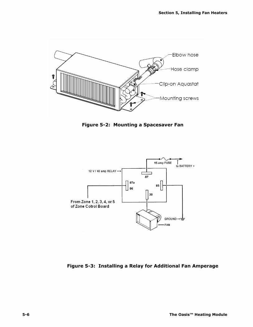
mount the fan units. See Figure 5-2: Mounting a Spacesaver Fan.
• Two-Speed Fan Switches – to enable low and high-
speed settings from inside the coach or yacht; for use with the ITR Cabin heater and Spacesaver fan.
• Three-Speed Fan Switches — to enable low, medium and high-speed settings from inside the coach or yacht; for use with the ITR defrost heater.
• Air Ducting — to allow you to install fans in a remote location (i.e. not directly adjacent to the interior space
to be heated) and duct the heated air to its output location. Also, air outlet plates to allow you to install ducting for one, two or three separate outlets
Section 5, Installing Fan Heaters
5-4 The Oasis™ Heating Module
(e.g. you can use one fan to heat two different areas by installing a dual air outlet plate).
5.3 What NOT to Do
• Don’t install more fans that require more heat than the Heating and Distribution Module can produce.
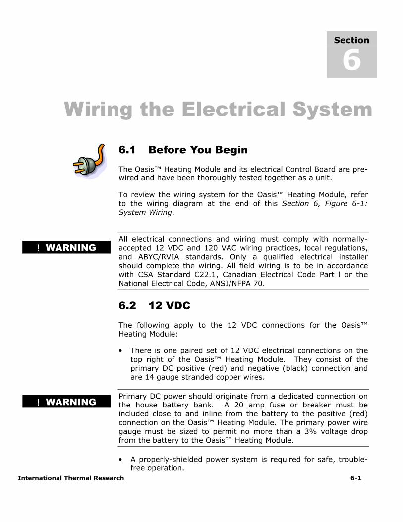
Your system will not run effectively. (If you choose to use a higher-draw fan motor (more than 5 amps), install a relay to handle the extra load; see Figure 5-3:
Installing a Relay for Additional Fan Amperage.)
• Don’t mount the return air outlet too close to the fan’s air intake source.
5.4 Mounting Locations
Carefully choose the mounting locations of your fans:
• Locate the fans to evenly heat the zone.
• Provision must be made to protect water lines from
freezing.
• Install fan at floor level or very near floor level, in order to optimize circulation.
• Allow a minimum 16 square inch (100 cm sq.) opening in the fan heaters’ mounting compartment to allow sufficient
intake of air.
ITR’s Spacesaver fan (pictured at left) has two stainless steel mounting brackets welded to the side of the case. It is
designed to be mounted horizontally on a flat surface. This fan can also be ordered with a right-hand or left-hand
hose configuration.
ITR’s standard cabin heater fan comes with loose stainless
steel brackets. The fan can be mounted on the floor or on the wall, either flat or on its side.
The thermostat should not be mounted on walls outside of
the zone because that could cause false temperature readings. Mount on interior walls and bulkheads, away from
windows, heater vents and cabin fan heaters.
ITR can suggest
optimal fan locations
if you provide a floor
plan of your coach or yacht.
Section 5, Installing Fan Heaters
International Thermal Research 5-5
5.5 Procedure
After choosing the appropriate mounting location and configuration:
1 Mount the fan using #10 sheet metal screws or wood screws, see Figure 5-2: Mounting a Spacesaver Fan.
2 If you are using ducting and a dual air outlet plate for any fan, limit the total length of duct for both outlets to 36” for optimum air output.
3 Select the appropriate mounting location for the thermostat, as well as any fan speed switches. You will
wire these up to the Zone Control Board in Section 9 –Installing the Distribution Module.
4 The zone control board can control up to 5 zones. The
cabin fan 1 lead (orange) can supply up to a maximum of 10 Amps. The other cabin fan leads 2-5 can supply up to a
maximum of 5 Amps each. The total current draw is not to exceed 18 Amps for all cabin fan leads.
5 If the system requires higher amperage draws, install a separate relay to power the fans. This relay will use the existing fan circuit as a signal and must be wired to a
secondary power source (not the heater’s control board). See Figure 5-3: Installing a Relay for Additional Fan
Amperage.
6 To install plumbing lines to the fans, see Section 7 –Plumbing the System.
Section 5, Installing Fan Heaters
5-6 The Oasis™ Heating Module
Figure 5-2: Mounting a Spacesaver Fan
Figure 5-3: Installing a Relay for Additional Fan Amperage
International Thermal Research 6-1
Wiring the Electrical System
6.1 Before You Begin
The Oasis™ Heating Module and its electrical Control Board are pre-wired and have been thoroughly tested together as a unit.
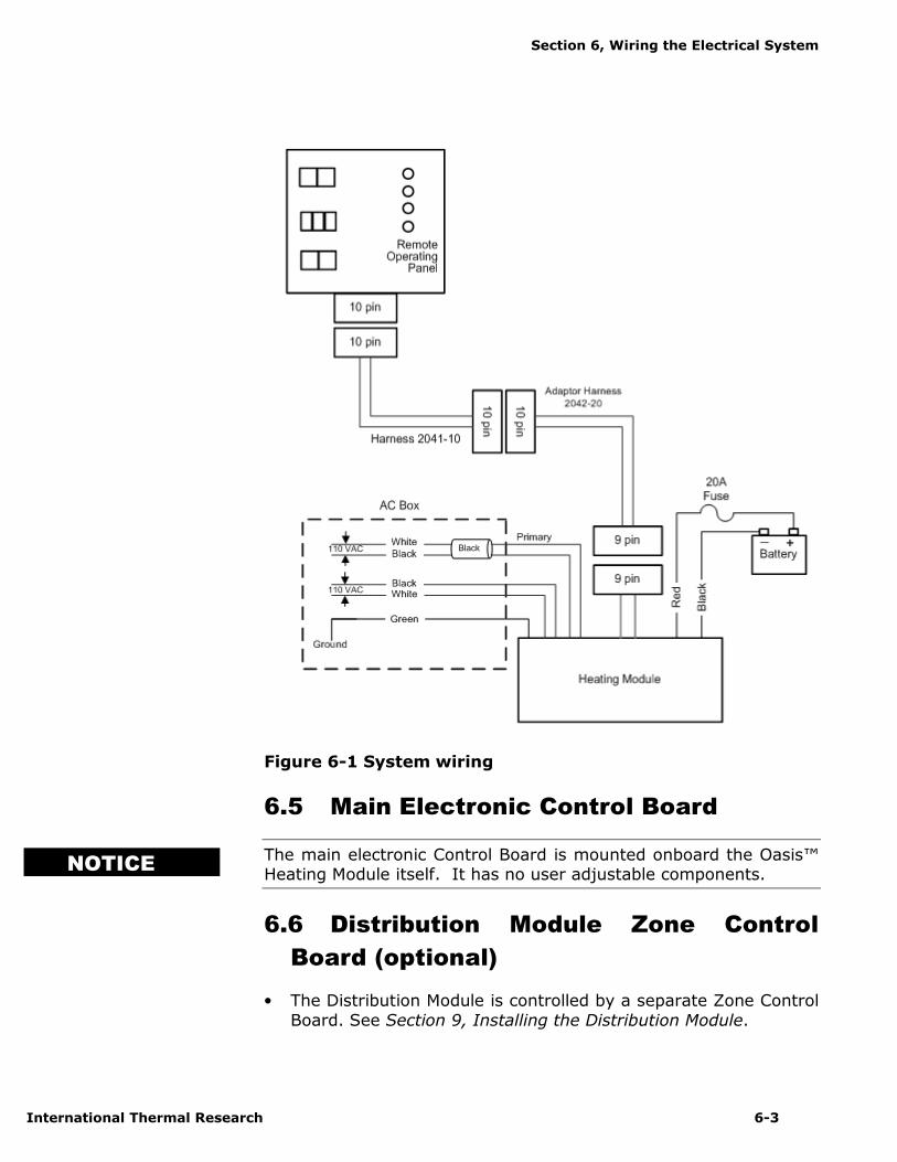
To review the wiring system for the Oasis™ Heating Module, refer
to the wiring diagram at the end of this Section 6, Figure 6-1: System Wiring.
All electrical connections and wiring must comply with normally-accepted 12 VDC and 120 VAC wiring practices, local regulations,
and ABYC/RVIA standards. Only a qualified electrical installer should complete the wiring. All field wiring is to be in accordance with CSA Standard C22.1, Canadian Electrical Code Part l or the
National Electrical Code, ANSI/NFPA 70.
6.2 12 VDC
The following apply to the 12 VDC connections for the Oasis™
Heating Module:
• There is one paired set of 12 VDC electrical connections on the
top right of the Oasis™ Heating Module. They consist of the primary DC positive (red) and negative (black) connection and are 14 gauge stranded copper wires.
Primary DC power should originate from a dedicated connection on the house battery bank. A 20 amp fuse or breaker must be
included close to and inline from the battery to the positive (red) connection on the Oasis™ Heating Module. The primary power wire
gauge must be sized to permit no more than a 3% voltage drop from the battery to the Oasis™ Heating Module.
• A properly-shielded power system is required for safe, trouble-free operation.
Section
6
!!!! WARNING
!!!! WARNING

Section 6, Wiring the Electrical System
6-2 The Oasis™ Heating Module
6.3 120 VAC
• The Oasis™ Heating Module is equipped with two 1500 watt, 120 VAC immersion elements (other voltages and frequencies
are available). The connections for the electrical supply are on the top left side of the Oasis™ Heating Module, under a cover,
labeled AC power.
• The power wires for the AC immersion elements are three 14 gauge stranded copper leads that use standard AC color code
(black-hot, white–neutral, green-ground). These are to be connected using standard 120 VAC electrical connectors and
terminals.
• There are two sets of power wires, one set with black heat shrink (primary) and one set without heat shrink (secondary).
Each individual set must be connected to a separate AC circuit breaker. The primary set is connected to the single AC element
side of the Oasis™ Heating Module. The secondary set of wires is connected to the other AC element. If only one AC circuit
breaker is available, you must connect to the primary wire set only. Once the connections are completed, the wires are to be inserted back into their compartment and the cover secured.
• The ground wire (green) is shared between the two connections.
Do not operate the electric immersion elements until water is added
to the Oasis™ Heating Module and Distribution Module, and all trapped air has been removed.
6.4 Remote Operating Panel Cable
• One connection on top of the Oasis™ Heating Module is a multi- wire, sheathed cable with a 9 pin connector. This connects to a
matching connector on a short adapter cable. The other side of the cable has a 10 pin connector that connects to a 25’ remote cord. This remote cord then plugs directly into the Remote
Operating Panel. Refer to Figure 6-1: System Wiring.
• If the Distribution Module is used, refer to Section 9, Installing
the Distribution Module.
NOTICE
Section 6, Wiring the Electrical System
International Thermal Research 6-3
Figure 6-1 System wiring
6.5 Main Electronic Control Board
The main electronic Control Board is mounted onboard the Oasis™ Heating Module itself. It has no user adjustable components.
6.6 Distribution Module Zone Control
Board (optional)
• The Distribution Module is controlled by a separate Zone Control
Board. See Section 9, Installing the Distribution Module.
NOTICE

Section 6, Wiring the Electrical System
6-4 The Oasis™ Heating Module
6.7 What NOT to Do
Never shut off the Oasis™ Heating Module power via an inline
battery or master switch while the system is running. Never disconnect the battery when the Oasis™ Heating Module is running, and never disconnect the battery while the inverter is charging. Do
not wire the Oasis™ Heating Module through a disconnect that is used as a normal shut-down of the DC system.
Doing either will severely damage the Oasis™ Heating Module because it fails to automatically purge the combustion chamber. Such damage is detectable upon inspection and will not be covered
under warranty. Always shut the system off using the normal system controls, after it has completed its purge and cooled down
the combustion chamber.
NOTICE
International Thermal Research 7-1
Plumbing the System
7.1 Before You Begin
For efficient and safe operation of the Oasis™ Heating Module, follow all recommendations for properly installing the plumbing system. Any deviations from these must be approved in advance by
ITR.
The Oasis™ Heating Module when attached to the Distribution
Module (optional) must use the following:
Use only a non-toxic, propylene glycol based coolant with additives
generally recognized as safe ”GRAS” by the FDA in the coolant side of the Distribution Module (including engine loop).
For an efficient Oasis™ Heating Module operation, you must:
• Minimize heat loss from the Heating Module and hoses.
• Follow the flow directions for the fluids in the Heating Module.
Figure 9-3: Plumbing for Five Zones Using the Distribution Module in Section 9, Installing the Distribution Module shows a typical plumbing layout for circulating coolant from the Oasis™
Heating Module, then to the Distribution Module, and finally to the cabin fans.
7.2 Plumbing Installation
The plumbing installation should consider the following:
• The Oasis™ Heating Module has a filler neck located on the top of the unit and is equipped with a seven (7) pound radiator cap.
Section
7
!!!! DANGER
When heat is called
for, the distribution
pump in the
Distribution Module
(optional) sends
heated fluid out to the cabin fans.
Section 7, Plumbing the System
7-2 The Oasis™ Heating Module
Ensure a four (4) quart minimum overflow bottle is attached to the filler neck.
• The return and supply coolant plumbing connections are on the top of the Oasis™ Heating Module and are 1/2” male NPT
fittings. The return coolant input to the Oasis™ Heating Module is a connection labeled “Inlet” and the supply coolant output from the Oasis™ Heating Module is a connection labeled “Outlet”.
Ensure proper direction of flow. Refer to Figure 7-1: Heating Module for the location of the fittings.
• Two 1/2” NPT pipe to 3/4” hose barb fittings (not supplied) must be fitted into the Oasis™ Heating Module connections and tightened to a leak free condition using an appropriate thread
sealant.
• Hose and/or tubing used to connect to the Oasis™ Heating
Module or Distribution Module input and output connections must be heavy duty heater hose, minimum 3/4” I.D, or 5/8” PEX.
All fittings on the Oasis™ Heating Module require two wrenches
when tightening. One wrench must be placed on the tank fitting and held in place to prevent this fitting from being overstressed.
The other wrench can be used to tighten the matching half of the fitting onto it. Failure to follow this procedure will damage the
Oasis™ Heating Module and the fittings.
Do not operate the Oasis™ Heating Module until a proper
water/anti-freeze solution has been added to the Oasis™ Heating Module and the heating system and all trapped air has been bled.
An inadequate mixture may cause system circulation problems and potential Oasis™ Heating Module damage and/or personal injury. Use only a non-toxic, propylene glycol based coolant with additives
recognized as safe “GRAS” by the FDA. Refer to the anti-freeze manufacturer recommendations for instructions for your application.
NOTICE
! DANGER

Section 7, Plumbing the System
International Thermal Research 7-3
Figure 7-1 Heating Module
All fittings, hose and/or tubing involving the domestic water component of the Distribution Module, must be approved for use
with domestic water and rated for the domestic water system pressure
• All plumbing lines must be run and secured so as to prevent damage, chafing and kinking
• Ensure that the coolant flow is adequate through the Oasis™ Heating Module and the system. An indication of inadequate flow is, when the Oasis™ Heating Module is running and up to
normal operating temperature, the difference between the inlet and outlet coolant temperature to the Oasis™ Heating Module is
less than 20F.
• The Distribution Module contains three distribution pumps and
one heat exchanger and is pre-wired and pre-plumbed for ease of installation.
• The Heating and Distribution Modules should be filled and flushed
prior to operation to remove any foreign debris.
NOTICE
Section 7, Plumbing the System
7-4 The Oasis™ Heating Module
• Use heavy-duty heater hose or PEX tubing. Slip-on foam insulation coverings may be used over the hose fittings to reduce
heat loss. Secure all hose connections with spring clamps.
• Air vents for the fluid circulation system are not supplied, but
may be optionally installed to help bleed air from the system.
7.3 What NOT to Do
The Oasis™ Heating Module’s circulating water pump is one of the
most critical parts of the system. Never let the pump run dry or you will damage the impeller. This is not covered under warranty.
Don’t use low-quality heater hose.
Don’t let the hose come into contact with solvents, which may cause it to soften and swell. If there is any risk that solvents may
contact the hose, insert it into PVC plastic tubing for protection.
7.4 Installation Procedure
To install and connect the Oasis™ Heating Module and heater hose:
1 The supply and return coolant connections are on top of the Oasis™ Heating Module and are 1/2” male NPT fittings. The return coolant input to the Oasis™ Heating Module is labeled
“Inlet” and the supply coolant output from the Oasis™ Heating Module is labeled “Outlet”. Ensure proper direction of flow.
2 Two male 1/2” NPT x 3/4” hose barbs (not supplied) must be
fitted into the supply and return fittings and tightened to a leak free condition.
If the Distribution Module is to be used with the Oasis™ Heating Module, refer to Section 9, Installing the Distribution
Module.
NOTICE

Section 7, Plumbing the System
International Thermal Research 7-5
3 If the Distribution Module is not utilized, connect the cabin fan heater supply lines to the supply coolant “Outlet” from the
Oasis™ Heating Module. Ensure there are no kinks or sharp bends that might restrict the fluid flow. See Figure 7-2: Three
Approved Methods of Installing Heater Hose (Consult ITR for Alternative Methods and Products) for methods of attaching the heater hose.
Connect the cabin fan heater return lines to the return coolant “Inlet” on the Oasis™ Heating Module. Ensure there are no
kinks or sharp bends that might restrict the fluid flow.
4 Fill the Oasis™ Heating Module through the filler neck with the
recommended propylene glycol/water anti-freeze solution and bleed all trapped air.
Do not operate the Oasis™ Heating Module until the proper water/anti-freeze solution has been added to the Oasis™ Heating Module and the heating system and all trapped air has
been bled. An inadequate mixture may cause system circulation problems and potential Oasis™ Heating Module
damage and/or personal injury.
Use only a non-toxic, propylene glycol based coolant with additives recognized as safe “GRAS” by the FDA. Refer to the
anti-freeze manufacturer recommendations for instructions for your application.
Figure 7-2: Three Approved Methods of Installing Heater Hose
(consult ITR for alternative methods and products)
Section 7, Plumbing the System
7-6 The Oasis™ Heating Module

International Thermal Research 8-1
Operating the Oasis™ Heating
Module
This section describes the features, operation and maintenance of your new Oasis™ Heating Module. READ THESE
INSTRUCTIONS AND SAVE FOR REFERENCE.
8.1 Features of Your Oasis™ Heating
Module
The Oasis™ Heating Module uses a diesel burner (12 VDC)
controlled by a multi-functional electronic controller as the primary source of heating coolant fluid (anti-freeze and water).
Two 1500 Watt, 120 VAC immersion elements are used as secondary heat sources. The Oasis™ Heating Module heats the coolant fluid to provide a source of heat for all hydronic space
heating needs. When used with the Distribution Module and its integral distribution pumps, the Oasis™ Heating Module has the
ability to circulate the coolant fluid to all space heating areas. It can also provide a supply of domestic hot water using the integral heat exchanger in the Distribution Module.
Other features of the Heating Module include:
• A high-temperature, stainless steel burner and stainless steel
jacket.
• 8.2 US gallon welded insulated stainless steel coolant tank that minimizes heat loss and optimizes heat recovery.
• Low coolant level switch on the tank.
• Easy to install, completely modular and field serviceable with
Heating Module hookups and connections easily accessible from the front and top of the Oasis™ Heating Module.
• Quiet operation and low power consumption.
Section
8
Section 8, Operating the Heating Module
8-2 The Oasis™ Heating Module
• Low pressure fuel system with built-in fuel pump.
• Fuel efficient burner capable of burning a wide variety of
diesel-based fuels.
• Exhaust has minimal smoke and smell.
• Fan assisted sealed combustion is designed to use outside combustion air.
• Simple, low amperage draw ignition.
• Electronically-controlled system with:
• Automatic safety shutdown.
• Manual-reset aquastats for safety overheat protection. • LED indicators on the Control Panel for diagnostics. • Patented, proprietary Flame Sensor.
• Heating Module Remote Operating Panel with ON/OFF switch
for the diesel burner, AC elements, and engine heat.
• Heating Module Control Panel with buttons for Power, Bypass, Reset, and indicator LED’s for operational and diagnostic
information;
Available with the Optional Distribution Module:
• Three distribution pumps, one heat exchanger for heating multiple zones, engine heat function, and also producing
domestic hot water (mixing valve included). Also includes filling valves for easy filling/purging.
• Zone Control Board for controlling up to five space heating
zones.
8.2 Your Heating Module Model
As the user, you must be fully aware of the controls and
operating features particular to your model of The Oasis™ Heating Module. This is essential for the proper functioning and
life of your Oasis™ Heating Module as well as protecting your warranty.
Your model can be identified by locating the serial number label on the outside case of the Oasis™ Heating Module. The serial
NOTICE
Section 8, Operating the Heating Module
International Thermal Research 8-3
number identifies the model type through the first series of letters and numbers.
The two types of Oasis™ Heating Modules are:
CH50M – Oasis™ Heating Module 8 Gallon
CH50V – Oasis™ Heating Module 16 Gallon
8.3 Operating Instructions for the
Oasis™ Heating Module
The Oasis™ Heating Module must be installed and connections
made in accordance with the recommendations in the Installation and Operating Manual prior to operating the module.
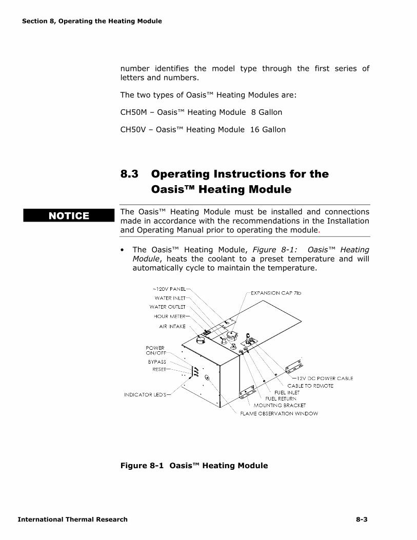
• The Oasis™ Heating Module, Figure 8-1: Oasis™ Heating Module, heats the coolant to a preset temperature and will automatically cycle to maintain the temperature.
Figure 8-1 Oasis™ Heating Module
NOTICE
Section 8, Operating the Heating Module
8-4 The Oasis™ Heating Module
8.4 Turning the Power to the Oasis™
Heating Module ON
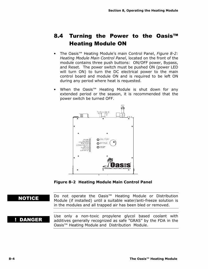
• The Oasis™ Heating Module’s main Control Panel, Figure 8-2: Heating Module Main Control Panel, located on the front of the
module contains three push buttons: ON/OFF power, Bypass, and Reset. The power switch must be pushed ON (power LED
will turn ON) to turn the DC electrical power to the main control board and module ON and is required to be left ON during any period where heat is requested.
• When the Oasis™ Heating Module is shut down for any extended period or the season, it is recommended that the
power switch be turned OFF.
Figure 8-2 Heating Module Main Control Panel
Do not operate the Oasis™ Heating Module or Distribution Module (if installed) until a suitable water/anti-freeze solution is
in the modules and all trapped air has been bled or removed.
Use only a non-toxic propylene glycol based coolant with
additives generally recognized as safe ”GRAS” by the FDA in the Oasis™ Heating Module and Distribution Module.
NOTICE
! DANGER
Section 8, Operating the Heating Module
International Thermal Research 8-5
8.5 Activating the Burner (Primary) and
AC Heat (Secondary) from the
Remote Operating Panel
Activating the Burner (Primary Heat Source)
• The burner switch on the Remote Operating Panel controls the
ON/OFF of the diesel burner (primary heat source). When the burner switch is turned ON, the diesel portion of the Oasis™
Heating Module will turn ON after ten seconds. The Burner LED will turn ON when the diesel burner has been activated. The burner will continue to operate until the coolant in the
Oasis™ Heating Module reaches the set operating temperature range. At this point, the diesel burner will turn
OFF. If the Oasis™ Heating Module coolant should cool down below this temperature range, the burner will again
commence firing and will continue until either the burner switch on the remote panel is turned OFF or the temperature range is again achieved. If the burner switch on the remote
panel is turned OFF, the burner stops and the Oasis™ Heating Module enters a two minute cool down stage prior to
completely shutting down.
Activating the AC Immersion Element(s) (Secondary Heat Source)
• Place the AC power switch on the Remote Operating Panel to either the one element or two element position. The AC Heat
(green) LED will turn ON indicating the AC element(s) are energized and the coolant is being electrically heated. They will continue to operate until the coolant in the Oasis™
Heating Module reaches the set operating temperature range. At this point, the elements will turn OFF. If the Oasis™
Heating Module coolant should cool down below this temperature range, the AC elements will again be energized and will continue until either the AC switch on the remote
panel is placed in the OFF position or the temperature range is again achieved. If the AC element switch on the remote
panel is turned OFF, the AC elements are de-energized and the AC Heat (green) LED turns OFF.
Section 8, Operating the Heating Module
8-6 The Oasis™ Heating Module
Activating the Burner and AC immersion Element(s) Jointly
• Turn the burner switch ON and place the AC power switch on the Remote Operating Panel to either the one element or two
element position. The Burner and AC Heat (green) LED’s will turn ON indicating the diesel burner and AC element(s) have been selected.
8.6 Activating the Cabin Fan Heaters
through the Thermostats
(Distribution Module Equipped Systems Only) (Burner or AC Heat or Engine Heat Source Available)
• Any thermostat connected to the Distribution Module’s Zone Control Board and calling for heat will cause the cabin fan
controlled by that thermostat to be enabled. The ITR cabin fan has a built-in aquastat that prevents the cabin fan from blowing cold air. Once the room temperature has reached the
temperature called for by the thermostat the cabin fan will turn off.
8.7 Activating the Domestic Hot Water
(Oasis™ Heating Module and Distribution Module used in Tandem) (Burner or AC Heat On)
• As long as heat is available in the Oasis™ Heating Module, the
Distribution Module (Optional) will respond to a call for domestic hot water. Ensure that a heat source has been
selected (i.e. Burner, AC, Engine). The production of the domestic hot water is continuous on the Burner operation and limited when using AC or Engine.
The domestic water pump is not a part of, nor controlled by the Distribution Module or The Oasis™ Heating Module.
8.8 Activating Engine Heat & Pre-heat
(Oasis™ Heating Module and Distribution Module used in Tandem) (Burner or AC Heat On)
Pre-heating the Engine
NOTICE

Section 8, Operating the Heating Module
International Thermal Research 8-7
• Turn the engine preheat switch on the Remote Operating Panel to the ON position with the burner or AC switch on. The
engine preheat pump and coolant pump will be activated once the Oasis™ Heating Module is in its set operating temperature
range. The engine will start to be preheated by the Oasis™ Heating Module.
• Note: An engine preheat pump does not come supplied with
the Distribution Module. The power and ground for the pump is available from the Distribution Module.
Engine Heat Used for Domestic Water or Space Heating
• Start the vehicle engine and let it come up to the normal operating temperature. Turn the burner switch on the
Remote Operating Panel to the ON position. The Oasis™ Heating Module will come up to the set operating temperature
range and will cycle OFF. The heat from the vehicle engine will be transferred from the engine to the domestic water and space heating loop.
8.9 Functions of the Remote Operating
Panel
• The Oasis Heating Module’s Remote Operating Panel, Figure 8-3: Remote Operating Panel, contains one ON/OFF
burner switch, one triple position AC element switch, one ON/OFF engine heat switch to control the optional engine pre-
heat pumps, and four LED’s indicating Burner activation, AC element activation (CH50 used in tandem with Distribution Module), module fault, and zone fault.
Figure 8-3 Remote Operating Panel
Section 8, Operating the Heating Module
8-8 The Oasis™ Heating Module
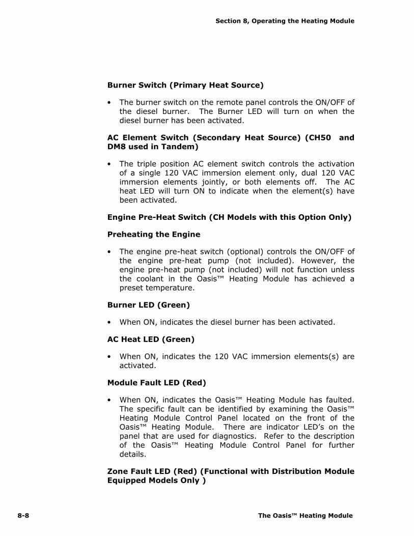
Burner Switch (Primary Heat Source)
• The burner switch on the remote panel controls the ON/OFF of the diesel burner. The Burner LED will turn on when the
diesel burner has been activated.
AC Element Switch (Secondary Heat Source) (CH50 and DM8 used in Tandem)
• The triple position AC element switch controls the activation of a single 120 VAC immersion element only, dual 120 VAC
immersion elements jointly, or both elements off. The AC heat LED will turn ON to indicate when the element(s) have been activated.
Engine Pre-Heat Switch (CH Models with this Option Only)
Preheating the Engine
• The engine pre-heat switch (optional) controls the ON/OFF of the engine pre-heat pump (not included). However, the engine pre-heat pump (not included) will not function unless
the coolant in the Oasis™ Heating Module has achieved a preset temperature.
Burner LED (Green)
• When ON, indicates the diesel burner has been activated.
AC Heat LED (Green)
• When ON, indicates the 120 VAC immersion elements(s) are activated.
Module Fault LED (Red)
• When ON, indicates the Oasis™ Heating Module has faulted.
The specific fault can be identified by examining the Oasis™ Heating Module Control Panel located on the front of the Oasis™ Heating Module. There are indicator LED’s on the
panel that are used for diagnostics. Refer to the description of the Oasis™ Heating Module Control Panel for further
details.
Zone Fault LED (Red) (Functional with Distribution Module Equipped Models Only )
Section 8, Operating the Heating Module
International Thermal Research 8-9
• When ON, indicates the space heating zone(s) has faulted. The specific fault can be identified by examining the
Distribution Module Zone Control Panel (optional) located beside the Oasis™ Heating Module. There are indicator LED’s
on the panel that indicate the problem. Refer to the description of the Distribution Module Zone Control Panel for further details.
8.10 Functions of the Heating Module
Control Panel
• The Oasis™ Heating Module’s Control Panel, Figure 8-2:
Heating Module Main Control Panel, contains three push buttons: ON/OFF power, Bypass, and Reset. In addition, it
contains nine LED’s indicating Power, AC Heat, Compressor, Fuel Pump, Combustion Fan, Igniter, Flame Out, Voltage and Low Water.
Power Button
• The power button turns ON/OFF the power to the control
board. The Power LED (green) turns ON when the power to the control board is ON.
Bypass Button
• The bypass button is for authorized service personnel only.
Reset Button
• The reset button when pressed resets the control board.
Power LED (Green)
• The power LED (green) turns ON when the power to the control board is ON. The LED flashes when the Oasis™
Heating Module is in Bypass mode.
AC Heat LED (Green)
• The AC Heat LED (Green) turns ON when a single or dual AC
immersion element(s) have been activated.

Section 8, Operating the Heating Module
8-10 The Oasis™ Heating Module
Compressor, Fuel Pump, Combustion Fan, Igniter (Green)
• The compressor, fuel pump, combustion fan, and igniter LED’s
(Green) turn ON when the component is ON, and will flash if the component is electrically open or shorted.
Flame Out (Red)
• The Flame Out LED (Red) turns ON when a flame fault has been detected.
Voltage Fault (Red)
• The voltage fault LED (Red) turns ON when a voltage fault has been detected.
Low Water (Red)
• The Low Water LED (red) turns ON when a low coolant level
in the Oasis™ Heating Module has been detected.
8.11 Functions of the Distribution Module
(Optional) Zone Control Panel
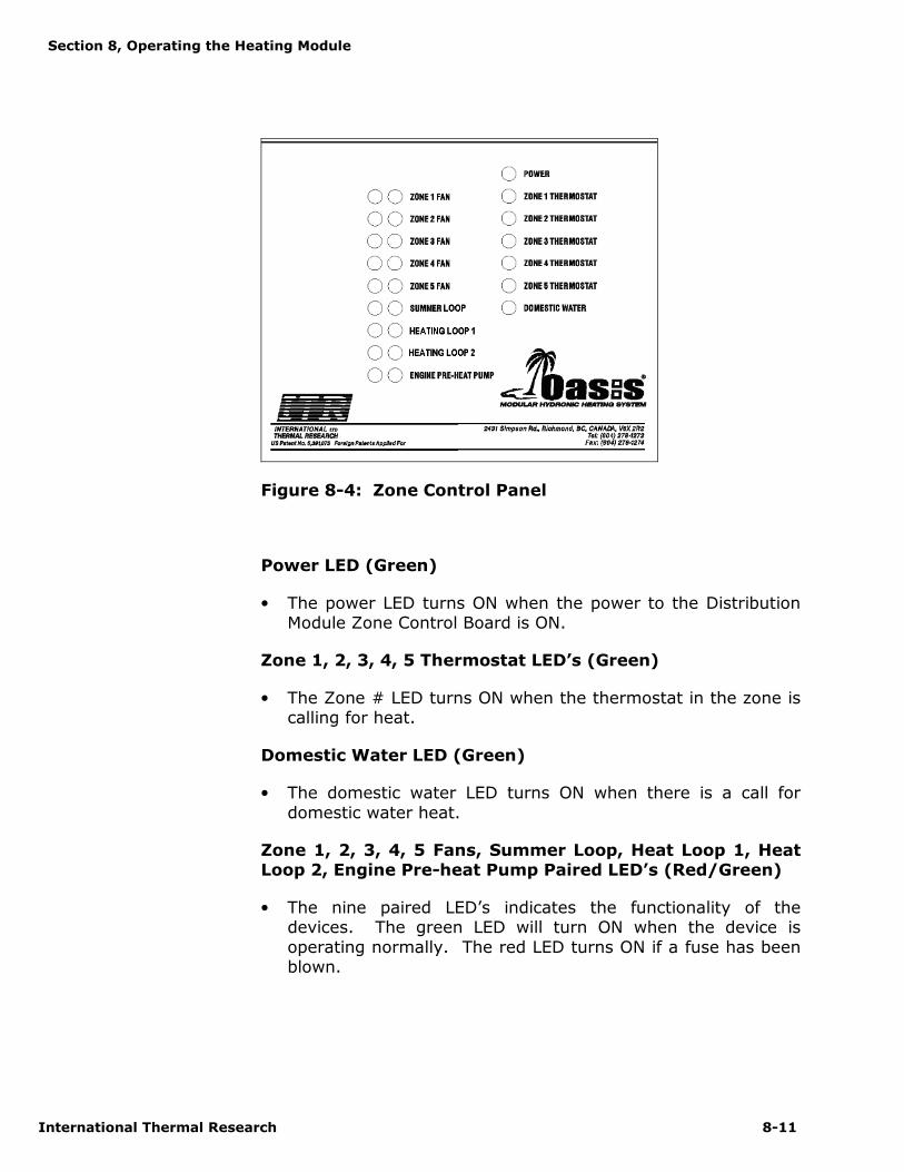
• The Distribution Module Zone Control Panel, Figure 8-4: Zone
Control Panel, contains seven green LED’s for Power, Zone 1, 2, 3, 4 and 5 Thermostat(s), and Domestic Water.
• It also contains nine matched pairings of red/green LED’s for
Zone 1, 2, 3, 4 and 5 Fan(s), Summer Loop, Heat Loop 1,
Heat Loop 2, and Engine Pre-heat Pump.
Section 8, Operating the Heating Module
International Thermal Research 8-11
Figure 8-4: Zone Control Panel
Power LED (Green)
• The power LED turns ON when the power to the Distribution Module Zone Control Board is ON.
Zone 1, 2, 3, 4, 5 Thermostat LED’s (Green)
• The Zone # LED turns ON when the thermostat in the zone is calling for heat.
Domestic Water LED (Green)
• The domestic water LED turns ON when there is a call for
domestic water heat.
Zone 1, 2, 3, 4, 5 Fans, Summer Loop, Heat Loop 1, Heat Loop 2, Engine Pre-heat Pump Paired LED’s (Red/Green)
• The nine paired LED’s indicates the functionality of the devices. The green LED will turn ON when the device is
operating normally. The red LED turns ON if a fuse has been blown.

Section 8, Operating the Heating Module
8-12 The Oasis™ Heating Module
8.12 Maintenance
Customer Monthly Maintenance: Check the following and correct as required:
• Coolant hoses and fittings for leaks and integrity.
• Check coolant level in the overflow bottle (3/4 full when
hot). Fill only when the system is COLD and in small quantities only to prevent overfilling.
• Exhaust fittings, connections, tubes for leaks, and
integrity.
• Exhaust and air-intake checked for no obstructions.
• Fuel lines, fittings for leaks and integrity.
• External fuel filter for clogging.
Annual Service Requirements: Perform the following:
• Prior to operation for the season, a factory service tune-up of the modular system should be performed
by trained service personnel. Only personnel familiar with the equipment modules should perform the service
tune-up. It is recommended that the dealer be contacted for this service or if not available, contact ITR for information on service resources.
• As a general guide, the regular maintenance items such as the igniter, fuel filters (internal and external), and air filter
(internal) should be replaced as opposed to inspected and cleaned. Their performance may be deteriorating and/or their remaining service life ending without any apparent
visual signs or operating symptoms.
• The major components such as the air compressor, fuel
pump, fuel nozzle, and combustion air fan should be examined for wear and should be replaced by the service technician as required.
• The combustion tube should be inspected by the service technician for wear and replaced if necessary. To access
the combustion tube, the front panel of the Oasis™ must be removed along with the burner box cover. The fuel block must then be removed from its mounting position.
Section 8, Operating the Heating Module
International Thermal Research 8-13
Finally, the burner and counter-flow tube must be taken out by removing the nuts holding the burner box in
position. If the tube is satisfactory, a thorough cleaning of the tube and burner chamber should be performed by
blowing out and vacuuming any ash and carbon buildup. Any build up on the surface of the burner chamber will cause the heater to lose efficiency.
• Regular inspection and maintenance is the only way to ensure safe, reliable and efficient operation of your heating
system.
8.13 Protecting the Heating Module and
the Optional Distribution Module
Protect the Oasis™ Heating Module and Distribution Module
(Optional) from temperature extremes and any dusty, dirty, corrosive environment.
Protect the module(s) and the system from cold temperatures and corrosion by using a proper mixture of anti-freeze and water.
Use only a non-toxic propylene glycol based coolant with additives generally recognized as safe “GRAS” by the FDA in the Oasis™ Heating Module and Distribution Module (Optional). Read
and follow the anti-freeze manufacturer’s instructions for the type of anti-freeze and mixture recommended for your
application.
Note that any domestic water in the Distribution Module
(Optional) will freeze in cold temperatures and will damage the internal parts. The Distribution Module and all associated
components must be completely drained and emptied of any domestic water before freezing temperatures are encountered.
8.14 General Troubleshooting
Ensure that your heating module has both sufficient battery voltage and ground, and coolant level as the module is designed not to allow operation if either are
incorrect (indicated by lit Voltage LED or Low Water LED on the Oasis™ Heating Module Control Panel) .
Burner Does Not Start Up
NOTICE
! DANGER
NOTICE

Section 8, Operating the Heating Module
8-14 The Oasis™ Heating Module
• Oasis™ Heating Module connected to 12 VDC power?
• Power button on Oasis™ Heating Module Control Panel
pushed ON? Power LED lit on Oasis™ Heating Module Control Panel?
• Burner switch on Remote Operating Panel ON? Burner LED lit on Remote Operating Panel?
• Main fuse or circuit breaker blown or tripped?
AC immersion elements do not activate
• Module connected to 120 VAC power?
• AC switch on Remote Operating Panel placed in the one or two element position? AC Heat LED lit on Remote Operating Panel?
• AC immersion elements circuit breakers tripped?
Burner Starts but Flame Faults
• Fuel supply present and adequate?
• Air-intake or exhaust not blocked or obstructed?
• Air in fuel line (white smoke from exhaust or popping
sound from exhaust)?
• Fuel filter (external) dirty?
• Restrict the fuel return line with needle valve or pinch off completely.
Burner Starts but Zone Faults
• Power LED on Distribution Module Zone Control Panel glowing green?
• Component matched LED pairings all glowing green on the Distribution Module Zone Control Panel?
International Thermal Research 9-1
Installing the Distribution
Module, DM12
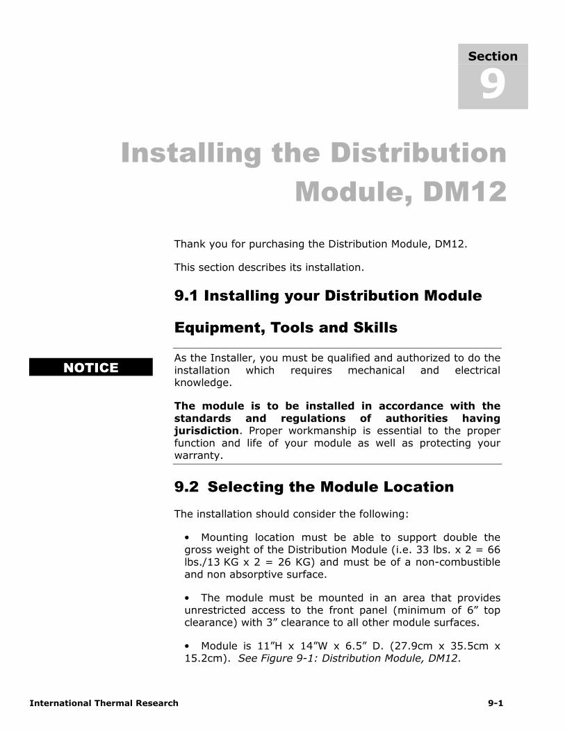
Thank you for purchasing the Distribution Module, DM12.
This section describes its installation.
9.1 Installing your Distribution Module
Equipment, Tools and Skills
As the Installer, you must be qualified and authorized to do the
installation which requires mechanical and electrical knowledge.
The module is to be installed in accordance with the
standards and regulations of authorities having jurisdiction. Proper workmanship is essential to the proper
function and life of your module as well as protecting your warranty.
9.2 Selecting the Module Location
The installation should consider the following:
• Mounting location must be able to support double the gross weight of the Distribution Module (i.e. 33 lbs. x 2 = 66
lbs./13 KG x 2 = 26 KG) and must be of a non-combustible and non absorptive surface.
• The module must be mounted in an area that provides unrestricted access to the front panel (minimum of 6” top clearance) with 3” clearance to all other module surfaces.
• Module is 11”H x 14”W x 6.5” D. (27.9cm x 35.5cm x 15.2cm). See Figure 9-1: Distribution Module, DM12.
Section
9
NOTICE
Section 9, Installing the Distribution Module
9-2 The Oasis™ Heating Module
• Module must be mounted using four, 1/4” through bolts using 1” diameter fender washers, lock washers and nuts.
The module must be mounted in the position as shown against a wall or on the floor.
Figure 9-1: Distribution Module, DM12
9.3 Selecting the Distribution Module
Zone Box Location
• Mount the Distribution Module Zone Box (containing the Zone Control Board) vertically, close to the Distribution
Module. Allow sufficient room to access the internal fuses as well as to view the display LED’s on the board itself.
• Mount the bracket against a wall using 2 flat head screws.
The distribution module zone box will then click onto the bracket.
Figure 9-2: Distribution Module Zone Box
Section 9, Installing the Distribution Module
International Thermal Research 9-3
• The Distribution Module is connected to the Distribution Module Zone Control Board through the electrical
connections located at the bottom of the Zone Control Board box. The distance apart is dictated by the length of the 9 pin
connector cord used.
9.4 Plumbing Installation
The plumbing installation should consider the following:
• The Distribution Module, see Figure 9-3: Distribution
Module Fittings Location. See the illustration for the location of the fittings.
Figure 9-3: Distribution Module Fittings Location.
All fittings on the Oasis™ Distribution Module require two
wrenches when tightening. One wrench must be placed on the module fitting and held in place to prevent this fitting from
being overstressed. The other wrench can be used to tighten the matching half of the fitting onto it. Failure to follow this
procedure will damage the Oasis™ Distribution Module, and the fittings.
NOTICE

Section 9, Installing the Distribution Module
9-4 The Oasis™ Heating Module
• The Domestic water connections are located on top of the module. The Cold water supply can be connected using a ½”
NPT fitting. The maximum water supply pressure to the module is 150 PSI (10 bar). The Hot water Outlet
temperature is regulated by an internal mixing valve factory set at 120F (49°C). If needed this valve can be adjusted in a range from 100F (38°C) to a maximum of 145F (63°C). For
more details about adjusting the temperature see chapter 9.9. A domestic water drain is provided for winterizing
purposes. This will prevent damage to the internal heat exchanger due to freezing water. See Figure 9-4: Domestic Hot water system plumbing.
All fittings, hose, tube and fitting sealant involving the domestic water must be food safe and approved for use
with domestic water and rated for the domestic water system pressure.
Figure 9-4 Domestic Hot Water System Plumbing.
• The engine heat/pre-heat connections are located on the side of the distribution module. Hot coolant from the engine
enters the module at the “engine heat inlet”. The “engine heat outlet” returns the coolant back to the engine supply. When the pre-heat function is installed an additional pump is
connected between the “engine heat outlet” and the engine supply. The module contains a red and black wire to connect
WARNING
Section 9, Installing the Distribution Module
International Thermal Research 9-5
this pump. The pre-heat switch on the remote control panel will activate this pump. See Figure 9-5: Engine heat/pre-
heat system plumbing.
Figure 9-5 Engine Heat / Pre-heat System Plumbing.
• The pre-heat pump wires are capped off to prevent accidental shorting. The pre-heat switch on the remote will
turn on power to the wires.
• The Distribution module contains two connections on the side panel to connect to the Oasis™ Heating Module. The
“Inlet from Heater” is connected to the hot coolant supply outlet on the Oasis™ Heating Module. The “Outlet to Heater”
is connected to the cold coolant return inlet on the Oasis™ Heating Module. It is recommended to use minimal ¾” ID hose for this connection. See Figure 9-6: Connecting to the
OASIS heating module.
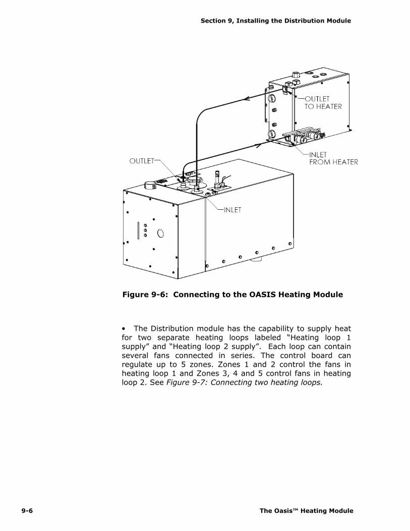
Section 9, Installing the Distribution Module
9-6 The Oasis™ Heating Module
Figure 9-6: Connecting to the OASIS Heating Module
• The Distribution module has the capability to supply heat
for two separate heating loops labeled “Heating loop 1 supply” and “Heating loop 2 supply”. Each loop can contain
several fans connected in series. The control board can regulate up to 5 zones. Zones 1 and 2 control the fans in heating loop 1 and Zones 3, 4 and 5 control fans in heating
loop 2. See Figure 9-7: Connecting two heating loops.

Section 9, Installing the Distribution Module
International Thermal Research 9-7
Figure 9-7: Connecting two Heating loops.
Use only a non-toxic propylene glycol based coolant with
additives generally recognized as safe ”GRAS” by the FDA in the coolant side of the Distribution Module. Refer to the anti-freeze manufacturer recommendations for instructions for your
particular application.
Do not operate the Oasis™ Heating Module and Distribution
Module, until the heater tank, overflow bottle and the circulation loops are filled with coolant and there is a steady
flow (with no air bubbles visible) of returning coolant flowing into the large bucket used during the filling procedure as
outlined below.
All plumbing lines must be run and secured so as to prevent
damage, chafing and kinking.
9.5 Filling/Purging the heating system
The Distribution module contains two valves with ½”NPT connections to be used for filling the heater tank and
circulation loops. To initially fill and bleed the air out of the system, do the following:
! DANGER
WARNING NOTICE NOTICE

Section 9, Installing the Distribution Module
9-8 The Oasis™ Heating Module
1. Connect a hose to the outlet of a self priming diaphragm pump and to the “fill inlet valve” on the distribution module.
Attach a hose to the inlet of the self priming diaphragm pump and place the other end in a large container (5 gallon/20 ltrs.
Bucket) filled with a 50/50 (or a pre-mixed) solution of propylene glycol and water (see Figure 9-8).
Use clamps to secure all hose connections
Be sure to use FDA–GRAS (Generally Recognized as Safe) boiler antifreeze
2. Connect a hose to the “fill outlet valve” on the distribution module and submerge the other end of this hose in a large
container of coolant – 5 gallon/20 ltrs. bucket (see Figure 9-8).
Figure 9-8: Initial fill up Oasis system
NOTICE
NOTICE

Section 9, Installing the Distribution Module
International Thermal Research 9-9
3. Fill the overflow bottle (usually located in the engine compartment) with coolant to the “Max fill up when Cold” level.
4. Open both valves on the Distribution module.
5. Turn ON the self priming diaphragm pump. The coolant will
flow from the large container through the distribution module, the coolant tank inside the heater and the heating loops inside the coach and return to the container. It will be necessary to
fill up the container with more coolant as the air is being displaced from the system.
Check the coolant level in the overflow bottle and top-up if needed. Replenish the coolant in the large container
as needed. Do not let the self-priming pump draw in air and do not let the coolant level drop in the overflow bottle.
6. Allow the returning coolant to flow into the large container until no large air bubbles can be seen. It will take some time to
completely displace all of the air in the system.
Alternative procedure for filling the heater tank and overflow bottle.
To skip this alternative procedure proceed to step 7.
Only use this procedure with two people; one to monitor the level of coolant in the overflow bottle while the
other person controls the position of the filling outlet valve on the Distribution module.
When the coolant in the large container remains at the same level, slowly close the filling outlet valve on the Distribution
Module. It is not necessary to close the filling outlet valve all the way as the system will begin to pressurize by reducing the flow with a partially closed valve. The pressure build-up will
force coolant from the heater tank which will flow out of the overflow nipple on the pressure relief cap into the overflow
bottle. Have another person monitor the level in the overflow bottle to let you know when the “Max fill up when Cold” level is
NOTICE
NOTICE
Section 9, Installing the Distribution Module
9-10 The Oasis™ Heating Module
reached. Once this level is reached open the filling outlet valve and let the coolant continue to flow into the large container.
Be careful when following this alternative procedure as the coolant will flow with some force out of the
overflow nipple and fill the overflow bottle very quickly. If the pressure builds too quickly, coolant can
escape from under the cap and spill onto the top of the heater. To prevent this, open the filling outlet valve enough to relieve the pressure and slow the flow.
7. It is necessary to ensure trapped air is displaced from both circulation loops. To do so; while the self priming pump is
operating and there is a steady flow of coolant returning to the large container, pinch-off both circulation loop hoses coming from
the top of the Distribution Module. These hoses are labelled “Heating loop 1 Supply” and “Heating loop 2 Supply”. (see figure 9-3). This will force coolant through the heat exchanger, summer
pump and coolant tank inside the heater. When no air can be seen coming from the return hose, remove a clamp from one hose
and check for air bubbles. If no air bubbles are visible, replace this clamp, remove the other clamp and check for air bubbles. When there is steady stream of coolant flowing from the return
hose and no air bubbles can be seen remove the last clamp. Let the coolant continue to flow freely through the system.
Before proceeding, there must be a steady flow of coolant returning to the larger container and no air
bubbles are coming from the submerged return hose
8. Turn on the pump activation (bypass) switch, located on top of
the zone box (see fig. 9-8), this will activate the pumps inside the distribution module and help with the filling/purging process. Let the self priming pump and the circulation pumps run for 10 or 15
minutes. At this point there should be very little air, if any, coming from the return coolant.
Check the coolant level in the overflow bottle and top-up if needed
WARNING
WARNING
NOTICE

Section 9, Installing the Distribution Module
International Thermal Research 9-11
9. Once coolant in the container remains at the same level and there is no air in the return stream, turn off the diaphragm
pump and immediately close the outlet valve on the Distribution Module then close inlet valve. Do this in quick
succession so coolant does not flow back into the large container.
10. Turn off the pump bypass switch. The bypass switch should
always remain in the off position during normal operation.
11. The Oasis heating system is now ready for operation.
9.6 Electrical Connection
All electrical connections and wiring must comply with
normally-accepted 12 VDC wiring practices, local regulations and ABYC/RVIA standards. Only a qualified electrical installer should complete the wiring. All field wiring is to be in
accordance with CSA Standard C22.1, Canadian Electrical Code Part l or the National Electrical Code, ANSI/NFPA 70.
12 VDC
Primary DC power to the module should originate after the master disconnect switch from a dedicated connection on the
house battery bank.
• The power connection to the module from the power supply is through the Distribution Module Zone Control Board
itself. A 25 amp fuse or breaker must be included inline from the power source to the positive connection on the zone
board. The primary power wire gauge must be sized to permit no more than a 3% voltage drop from the power
supply to the zone board. There are no direct 12 VDC power connections onto the Distribution Module itself. Refer to Figure 9-9: Distribution Module Wiring.
WARNING

Section 9, Installing the Distribution Module
9-12 The Oasis™ Heating Module
9.7 Distribution Module Zone Control
Board
Multi-Pin Connectors
The Zone Control Board has four multi-pin connectors, see
Figure 9-3: Plumbing for Five Zones Using the Distribution Module, that are to be connected through connector cords
(supplied) to the matching multi-pin connectors as follows:
• 10 pin connector to Heating Module Remote Operating Panel.
• 8 pin connector to Heating Module (connector cord transitions to a 9 pin connector for the Heating Module).
• 12 pin connector to Distribution Module (connector cord transitions to a 9 pin connector for the Distribution Module).
• 14 pin connector to thermostat and cabin fan connector plug.
Cabin Fan leads
• The positive (red) lead from each cabin fan is to be attached to one of the trailing cabin fan leads, color coded
for zones, from the thermostat and cabin fan connector plug.
• The negative lead from each cabin fan is to be attached to a ground terminal (not provided) that is connected to a
battery ground.
• The cabin fan 1 leads (orange) can supply up to a
maximum of 10 Amps. The other cabin fan leads 2-5 can supply up to a maximum of 5 Amps each. The total current draw is not to exceed 18 Amps for all cabin fan leads.
• If the system requires higher amperage draws, install a separate relay to power the fans. This relay will use the
existing fan circuit as a signal and must be wired to a secondary power source (not the heater’s control board). See Figure 5-3.

Section 9, Installing the Distribution Module
International Thermal Research 9-13
Thermostat Leads
• The power lead to the thermostat is to be attached to a
power terminal (not provided) that is connected to the battery.
• The return lead from each thermostat is to be attached to one of the trailing thermostat leads, color coded for zones, from the thermostat and cabin fan connector plug.
Figure 9-9: Distribution Module Wiring
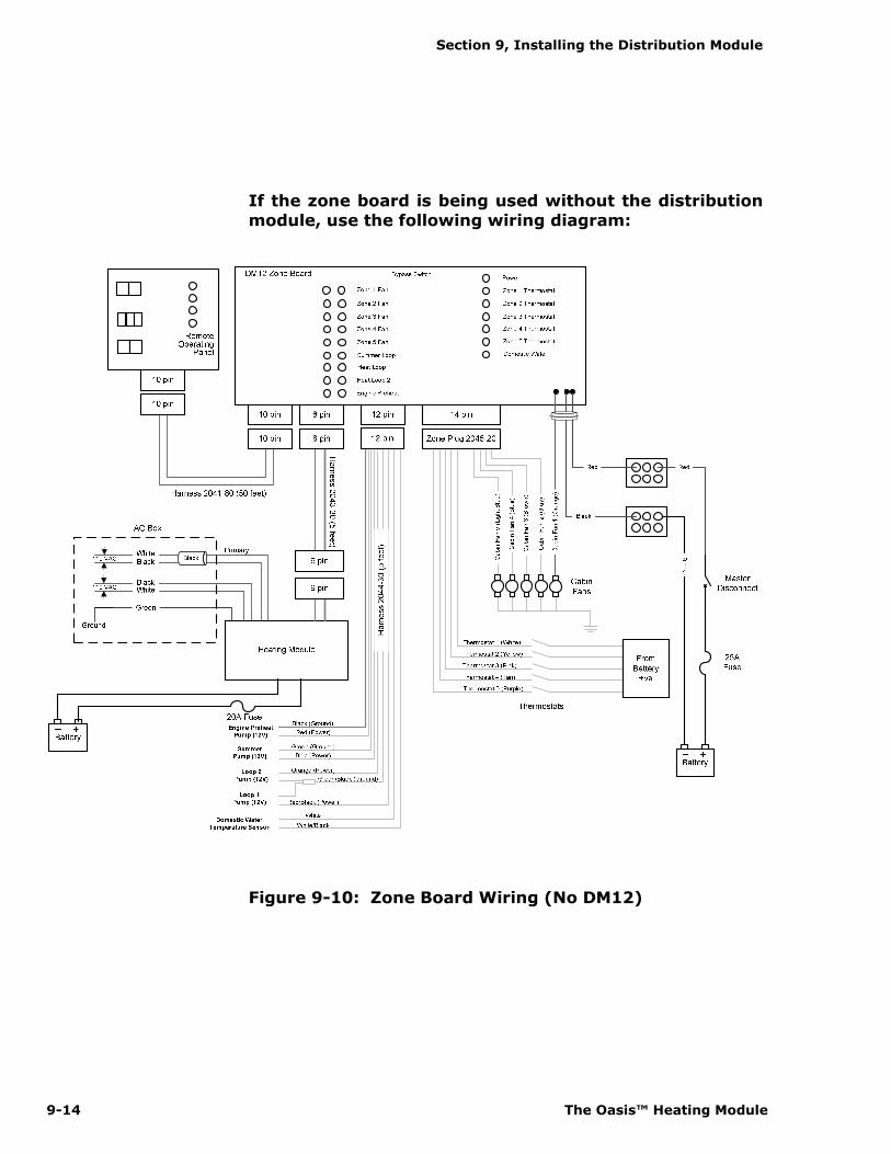
Section 9, Installing the Distribution Module
9-14 The Oasis™ Heating Module
If the zone board is being used without the distribution
module, use the following wiring diagram:
Figure 9-10: Zone Board Wiring (No DM12)
Section 9, Installing the Distribution Module
International Thermal Research 9-15
9.8 Inspection and Testing
After all components have been properly installed according to ABYC Industry Standards and Practices and the
recommendations of this Manual, the Distribution Module and Oasis™ Heating Module should be inspected using the
Inspection Check Sheet in this Manual. The Inspection Check Sheet is divided into relevant sections allowing each phase of the Inspection to be carried out systematically, and
then signed off by authorized personnel.
9.9 Hot water temperature adjustment
A thermostatic mixing valve located inside the distribution
module (DM12) allows for adjusting the temperature of the domestic hot water. The mixing valve is factory set to limit the
maximum water temperature to 120ºF (49°C) with a total hot water demand of 1.5 GPM or less, and an incoming water temperature of 60ºF (15ºC) or higher.
The mixing valve will compensate for temperature variations of incoming supply water and maintain the temperature to which
it is set. However, in some cases, the temperature of the incoming water and the flow-rate of individual faucets may
limit the ability of the DM12 to provide hot water at the temperature setting of the mixing valve, even if the mixing valve is set to its maximum. This is a normal operating
characteristic of any on-demand, continuous hot water system that does not rely on heat retained within a stored volume of
water. In this situation the temperature of the hot water may be increased by lowering the flow at the faucet and shower head.
To adjust the mixing valve, the front cover of the DM12 has to be removed; to do this, remove the 6 Philips head screws
holding the front cover to the case. The mixing valve adjustment knob is shown in the figure 9-11
WARNING NOTICE NOTICE
Section 9, Installing the Distribution Module
9-16 The Oasis™ Heating Module
Figure 9-11: Mixing valve location
The parts inside the Distribution module are HOT when in
operation. Use gloves when adjusting the mixing valve.
Turning the mixing valve knob left (clockwise from top view)
will increase the hot water outlet temperature and turning the knob right (counter-clockwise) will decrease the temperature.
WARNING

Warranty Information
January 2011 Page 1
Attention Purchaser and Installer
General Warranty
• ITR warrants the OASIS® CH50, OASIS COMBI, AND ZEPHYR® Heaters (referred to
as “heater(s)”) DISTRIBUTION MODULE and all accessories or other supplied
components with the original purchase to be free of defects in materials and
workmanship under design usage and service conditions for ONE (1) year from the
heater “in-service” date. Warranty replacement parts are covered for the remainder of
the heater’s warranty.
• You must install the Product in compliance with the specifications, standards, and
instructions in the Installation Manual.
• If you need to depart from the manual, you must first consult and obtain the written
approval of ITR. Otherwise, your warranty may be voided or limited.
• Systems that are not installed to the published installation instructions (unless with
prior written approval of ITR) will be ineligible for warranty coverage.
• Fill in the enclosed Warranty Card completely. It must be signed by the Owner and
returned to ITR within 30 days of the date of the original installation. The Owner
cannot transfer this warranty. Before mailing, make photocopies of the completed
Warranty Card for your records. It will be a valuable reference if you need warranty
repairs in the future.
Limited Warranty
The following warranties are in lieu of all other warranties and conditions. ITR makes no
other warranties, representations, or conditions, express or implied. Expressly excluded
are all implied or statutory warranties or conditions of merchantability of fitness for a
particular purpose, and those arising by statute or otherwise in law or from dealing or
trade usage.
The stated express warranties are in lieu of all liabilities or obligations for damages arising
out of or in connection with the delivery, use, performance, or licensing of the Product or
in connection with any services performed. In no event whatsoever will ITR be liable for
indirect, consequential, exemplary, incidental, special, or similar damages, including but
not limited to, lost profits, lost business revenue, failure to realize expected savings, other
commercial or economic loss of any kind or any claim against ITR by any other party
arising out of or in connection with the sale, delivery, use, performance, or repair of the
Product, or in connection with any services performed, even if ITR has been advised of the
possibility of such damages, whether based upon warranty, contract, or negligence. ITR’s
maximum liability shall not in any case exceed the contract price for the Products claimed
to be defective.
No one is authorized to increase, alter, or enlarge ITR’s responsibilities or obligations
under these warranties.
Warranty Information International Thermal Research
Page 2 January 2011
Owner’s Responsibilities
If any warrantable failures occur before the expiration of the warranty, the Owner must
give notice of such failures to ITR or to the authorized ITR dealer from which the Product
was originally purchased, and obtain written approval for the warranty repair.
The Owner is responsible for the following costs in case of a warrantable failure:
• shipping and insurance costs to deliver the defective Product to the dealer or ITR
(if necessary)
• all repairs made to equipment ancillary to the Product, including the vehicle, coach
engine, and other associated components of the vehicle in which the Product is
installed
• lodging, meals, and other incidental expenses incurred by the Owner as a result of a
warrantable failure
• “down time” expenses and all business costs and losses resulting from the warrantable
failure
Not Covered Under Warranty
Warranty will be voided or not extended in the following circumstances:
• Owner fails to notify ITR or the authorized ITR dealer from which the Product was
originally purchased about a warrantable failure and to obtain prior written approval for
warranty repair.
• Original serial number on Product or electrical control board has been removed,
altered, or is unreadable.
• Product has been modified or uses non-standard parts not approved by ITR.
• Product has been abused (such as by dropping it), damaged, vandalized, or has
received improper maintenance.
• Product has been run dry or operated without appropriate antifreeze, causing damage
to the heat exchanger, pump seals, etc.
• Product has been exposed to an environment detrimental to its effective operation,
such as excessively wet, dirty, or hot areas.
Also not covered under warranty:
• Parts or Products no longer within the manufacturer’s warranty period.
• Parts or Products installed or used in a manner contrary to ITR’s printed instructions
without ITR’s prior written permission.
• Normal wear and tear of parts, including but not limited to, fuel filter, air filter, nozzles,
fuses, ignitor, electrical motors, fuel pumps, air compressors, and carbon brushes.
• Product malfunctions due to improper installation of parts or Products, including but
not limited to malfunctions causing inadequacies in air, fuel, or coolant flow; voltage
problems due to improper wiring; and shock or vibration.

International Thermal Research Warranty Information
January 2011 Page 3
• Progressive damage to the engine or vehicle caused by failure of the Product or an
improper installation.
• Diagnosis or repairs to fix problems not directly related to the Product or due to empty
fuel tanks or poor fuel quality, fuel additives, acidic water, electrolysis, or any chemical
reactions.
• Travel time and expenses by an ITR dealer.
• Removal and re-installation expenses for the ITR heater.
Customer Service Calls
ITR warrants the ITR heater and the Dealer warrants the installation.
If you have a service problem, first check the Troubleshooting section of the Owner’s
Manual to determine if your problem is addressed. Also ensure you are familiar with the
design and installation setup.
When calling ITR or the Dealer with a service problem, have the following information
ready at hand:
• model number and serial number of the Product
• a detailed description of the problem
• your Installation Manual and Owner’s Manual
Depending on your location, an authorized service person may be able to visit your coach
or yacht to help troubleshoot problems and repair your Product. Such service calls are at
the Owner’s expense. Regardless, you must obtain written approval from ITR or the Dealer
for any warranty repair before it is undertaken. All repairs done under warranty are
subject to the terms and conditions of the flat-rate manual.
Returns
If a service call by an authorized service person is not feasible, the Owner must do the
following to obtain warranty service:
1. Immediately contact ITR (or your Dealer) and provide a full description of the
problem.
2. Obtain (in writing) a Return or Repair Material Authorization (RMA) number from ITR
for any warranty, return, repair, or service. ITR will refuse any return package and
will not authorize service or repairs without a RMA number. (For repairs by
authorized Dealers, the dealer must obtain an authorized RMA number from ITR
before warranty work commences.)
3. When shipping your Product, pack securely, show the RMA and serial number of the
Product on the outside of the shipping container, and ship prepaid and insured.
4. Provide written details of the problems, date of installation, proof of purchase, and a
return address.

Warranty Information International Thermal Research
Page 4 January 2011
After repair or replacement of the Products still under warranty, ITR will pay return
shipping charges. All repairs done under warranty are subject to the terms and conditions
of the flat-rate manual.
Telephone / Email Service
Service information given over the telephone, by fax or by email is given only in good faith
as an accommodation to the customer. Such information should not be relied upon without
an independent verification of its applicability to the customer’s particular situation. For
customer service or other information, contact:
IN CANADA: IN THE UNITED STATES:
2431 Simpson Road 11915 NE 56th Circle, Suite B
Richmond, BC, Canada V6X 2R2 Vancouver WA USA 98682
Tel: 1-800-755-1272 or 604-278-1272 Tel: 1-800-993-4402 or 360-993-4877
Fax: 604-278-1274 Fax: 360-993-1105
Email: [email protected] Email: [email protected]
Website: http://www.itrheat.com