oasis at newman site classification report
TRANSCRIPT
Oasis at Newman Site Classification Report
Oasis at Newman - Camp extension
5057-P24
Prepared for Oasis at Newman
15 April 2020
Oasis at Newman Site Classification Report
Oasis at Newman - Camp extension
5057-P24

Oasis at Newman Site Classification Report
Oasis at Newman - Camp extension
15 April 2020 Construction Sciences Pty Ltd ii
Contact Information
Construction Sciences
ABN 74 128 806 735
3/4/53 Export Dr
East Arm, Darwin – NT, 0820
Australia
Telephone: (08) 8947 2780
www.constructionsciences.net
Document Information
Prepared for Oasis at Newman
Project Name Oasis at Newman - Camp
extension
File Reference CSWA0144 – Camp
Extension
Job Reference 5057-P24
Date 15 April 2020
Version Number 001
Document Control
Version Date Description of Revision Prepared
By
Prepared
(Signature)
Reviewed
By
Reviewed (Signature)
001 15/04/20 Preliminary Report RH
© Construction Sciences. Copyright in the whole and every part of this document belongs to Cardno and may not be used, sold, transferred, copied or reproduced in whole or in part in any manner or form or in or on any media to any person other than by agreement with Construction Sciences.
This document is produced by Construction Sciences solely for the benefit and use by the client in accordance with the terms of the engagement.
Construction Sciences does not and shall not assume any responsibility or liability whatsoever to any third party arising out of any use or reliance by any third party on the content of this document.
RK

Oasis at Newman Site Classification Report
Oasis at Newman - Camp extension
15 April 2020 Construction Sciences Pty Ltd 3
Table of Contents
1 INTRODUCTION 4
Objectives 4
2 INVESTIGATION WORK 5
Methodology 5
Laboratory Testing 5
3 SITE DESCRIPTION 6
Site location 6
Regional Geology 7
Groundwater 7
4 SUBSURFACE CONDITIONS 8
Subsurface Strata 8
Laboratory Test Results 10
5 GEOTECHNICAL ASSESSMENT 11
Site Classification 11
Footings 11
Earthworks 11
Excavatability 12
6 CONCLUSION 13
Appendices
Appendix A TEST PITS LOG
Appendix B LABORATORY TEST RESULTS
Appendix C CSIRO BTF 18-2011
Tables
Table 2-1 Field coordinates and termination depths of test pits ................................................................. 5
Table 4-1 Subsurface strata intervals ....................................................................................................... 8
Table 4-2 Summary of Particle Size Distribution (PSD) and Atterberg Limits (AL) ....................................10
Figures
Figure 3-1 Location of investigation area related to Newman and Newman’s airport ............................. 6
Figure 3-2 Site location of TP02, TP03 and TP04 ................................................................................. 6
Figure 3-3 Geological map with Test pits and borehole location ............................................................ 7
Figure 4-1 Material Encountered at TP02 ............................................................................................. 8
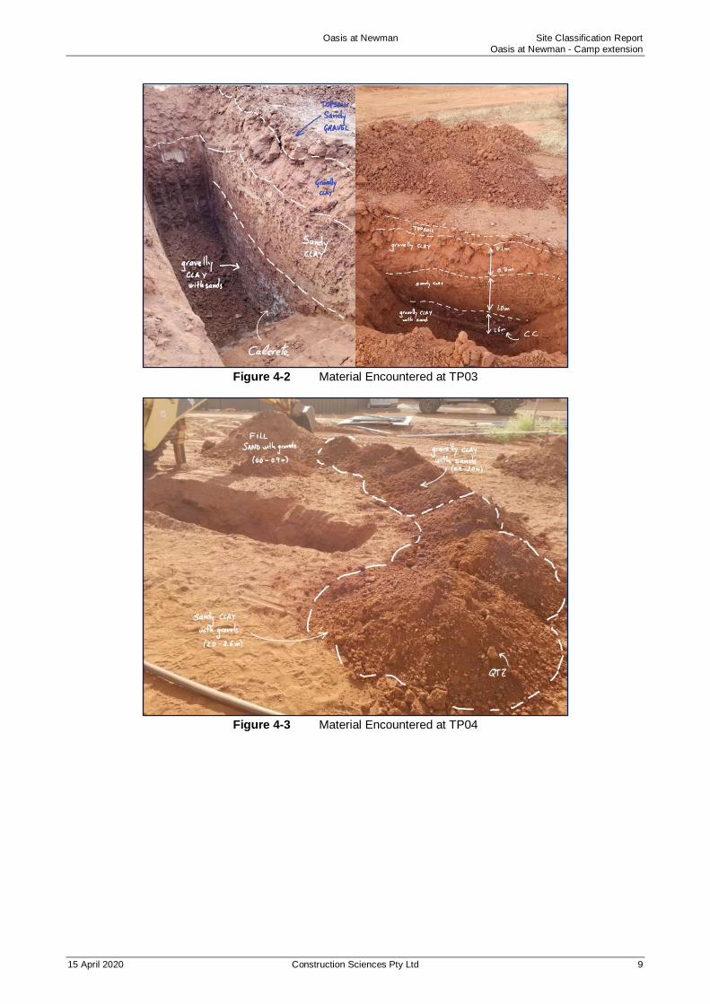
Figure 4-2 Material Encountered at TP03 ............................................................................................. 9
Figure 4-3 Material Encountered at TP04 ............................................................................................. 9
Figure 4-4 Samples TP04 and TP03 PSD test result ...........................................................................10

Oasis at Newman Site Classification Report
Oasis at Newman - Camp extension
15 April 2020 Construction Sciences Pty Ltd 4
1 INTRODUCTION
As requested by Oasis at Newman, a geotechnical investigation was carried out by Construction Sciences Pty
Ltd (CS) to provide a Site Classification report for the new building extension located at Oasis at Newman
Camp south of Newman in Western Australia.
Objectives
CS acknowledge the objectives of the investigation were to provide a site classification of the proposed camp
building extension site in accordance with AS2870-2011.
Therefore, the key objectives of the geotechnical investigation included:
• Complete a desktop study of the subject site to identify the likely near surface material to be
encountered;
• Assess the subsurface and geotechnical conditions at a suitable number of locations in order to
classify the proposed building footprint site in accordance with AS2870-2011: Residential slabs and
footings.
This report should be read in conjunction with the attached ‘General Notes’ included as Appendix A.

Oasis at Newman Site Classification Report
Oasis at Newman - Camp extension
15 April 2020 Construction Sciences Pty Ltd 5
2 INVESTIGATION WORK
Methodology
Fieldwork for the investigation was carried out on the 19th March 2020. The works were organized in two
stages, pre-works and fieldwork:
• Coordination was completed in advance with the nominated Oasis at Newman project manager to
confirm all access, DBYD, safety communication, PPE and personnel safety/induction documentation
submission and approval.
• Excavation, sampling and logging of three test pits (3) to a depth of 2.0 m below existing ground level.
The excavation was conducted using an 8 t 93R Komatsu backhoe provided by Oasis at Newman.
• Dynamic Cone Penetrometer (DCP) testing completed in accordance with AS1289.6.3.2
“Determination of the Penetration Resistance of a Soil – 9kg Dynamic Cone Penetrometer Test”. DCP
blow counts are included on the test pit logs.
• Bulk samples were recovered from each of the test locations for classification testing.
The field coordinates of the test pits are displayed in Table 2-1. The material encountered at each test pit
location is described in the test pit logs included in Appendix A.
Fieldwork was carried out in general accordance with Australian Standard, AS 1726:2017 ‘Geotechnical Site
Investigations’ and under full time supervision of an Engineering Geologist from CS.
Table 2-1 Field coordinates and termination depths of test pits
Test Reference Easting (m) Northing (m) RL (m)* Termination
depth (m)
TP02 785858.62 7409996.90 524 2.0
TP03 785821.10 7409969.67 524 2.0
TP04 785729.00 7409976.0 524 2.6
Notes:
(*) Approximate RL
Additional test pit was initially proposed, TP01. Due to time limitations on the day of the investigation, it was not excavated.
Laboratory Testing
Samples of representative strata were recovered and returned to our NATA accredited soils laboratory for
geotechnical tests. The following tests were carried out as per the CS proposal.
• Particle Size Distribution (PSD) test
• Atterberg Limits Tests
The laboratory test results are included in Appendix B and are discussed in Section 4.2. Laboratory testing
was carried out in accordance with Australian Standard AS1289 ‘Methods of Testing Soils for Engineering
Purposes’..

Oasis at Newman Site Classification Report
Oasis at Newman - Camp extension
15 April 2020 Construction Sciences Pty Ltd 6
3 SITE DESCRIPTION
Site location
The area of investigation at the proposed camp building extension has been presented below in Figure 3-1 and Figure 3-2 . The area is 0.47 km2 and it is located approximately 8.8 km south-west of Newman and 2.7 km north of Newman’s airport. Test pits were excavated on a flat surface within the area allocated for the building expansion on the north-east side of the current Camp.
Figure 3-1 Location of investigation area related to Newman and Newman’s airport
Figure 3-2 Site location of TP02, TP03 and TP04

Oasis at Newman Site Classification Report
Oasis at Newman - Camp extension
15 April 2020 Construction Sciences Pty Ltd 7
Regional Geology
Reference was made to the AUSGIN Geoscience Portal geological maps, which indicated that the investigation
locations were likely to be underlain by two main geological units:
• Quaternary deposits (Qa): Channel and floodplain alluvium gravel, silt, clay, locally calcrete.
• Quaternary deposits (Qrc): colluvium and/or residual deposits; gravel, sand, local calcrete andreworked laterite;
Figure 3-3 shows a geological map of the area, not to scale, in which variety of likely geological units can be
observed in the proximity of the site.
Figure 3-3 Geological map with Test pits and borehole location
Groundwater
Groundwater was not encountered at the time of investigation during excavation of the test pits. Groundwater
levels and seepages can fluctuate with seasonal and other environmental impacts.

Oasis at Newman Site Classification Report
Oasis at Newman - Camp extension
15 April 2020 Construction Sciences Pty Ltd 8
4 SUBSURFACE CONDITIONS
Subsurface Strata
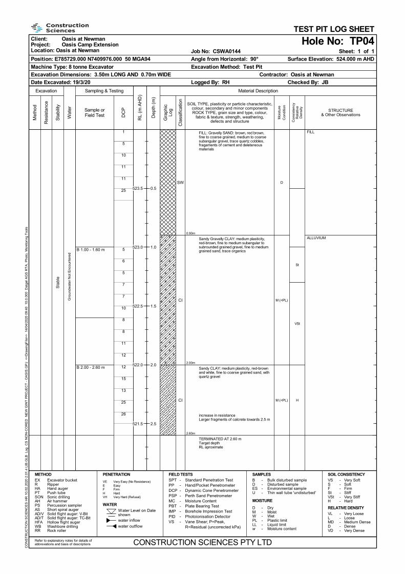
The subsurface profile encountered at each test location was observed to be consistent, with a small variance
in fine portions, being in general, sandy topsoil followed by sand, sandy/gravelly clay and calcrete with
ferruginous pisolites. Table 4-1 below presents test pits profiles encountered.
Table 4-1 Subsurface strata intervals
Soil Descriptions/ Depth (m)
TP
No.
FILL TOPSOIL ALLUVIUM
TC SAND with
gravels Sandy
GRAVEL Gravelly
CLAY Sandy CLAY
Gravelly CLAY with
sand
Sandy CLAY with gravel
MD-D D H H VSTF-H H
TP02 - - 0.0-0.3 0.3-0.9 0.9-2.0 - 2.0*
TP03 - 0.0-0.1 0.1-0.3 0.3-1.0 1.0-2.0 - 2.0*
TP04 0.0-0.9 - - - 0.9-2.0 2.0-2.6 2.6**
Notes:
a) All depts measured in metres below ground level at the time of investigation.
b) TC = Termination criteria
c) (*) = Target depth
d) (**) = Over the target depth
Test pit logs attached in Appendix A should be referred to for a detailed description of the surface soil
conditions. Figures 4-1 to 4-3 present materials encountered at each testing location.
Figure 4-1 Material Encountered at TP02
Oasis at Newman Site Classification Report
Oasis at Newman - Camp extension
15 April 2020 Construction Sciences Pty Ltd 9
Figure 4-2 Material Encountered at TP03
Figure 4-3 Material Encountered at TP04

Oasis at Newman Site Classification Report
Oasis at Newman - Camp extension
15 April 2020 Construction Sciences Pty Ltd 10
Laboratory Test Results
Samples recovered from the test pits were tested in the laboratory for field moisture content, Particle Size
Distribution (PSD) and Atterberg Limits (AL). Laboratory test report sheets are included in Appendix B, with
the results summarized in Table 4-2. An overview of the results of the geotechnical testing indicated the
following:
• Materials encountered were mainly alluvial fine-grained soils, gravelly clays with sands which exhibited
a general consistency in layering across site.
• Representative samples tested confirmed that the material up to 1 m depth is sandy clay, medium
plasticity with fine to medium grained sand; material from approximately 1.0 m comprised gravelly clay
with sands, becoming gradually sandy clay with gravels towards 2.0 m; materials from 1.0 m to the
end of test pits were noticed to contain more quartz and calcrete fragments.
Table 4-2 Summary of Particle Size Distribution (PSD) and Atterberg Limits (AL)
Borehole Depth (m) Material
Description
%
Sand & Gravel
%
Clay & Silt
Moisture Content
(%)
LL (%)
PI (%)
LS (%)
TP03 0.3 - 0.90 Sandy CLAY 42 58 13.4 44 21 11
TP04 2.0 – 2.6 Sandy CLAY with
gravels 60 40 9.8 43 19 9.8
Notes:
N = Not obtainable
The Figure 4-4 below illustrates the distribution of site representative samples TP04 and TP03.
Figure 4-4 Samples TP04 and TP03 PSD test result

Oasis at Newman Site Classification Report
Oasis at Newman - Camp extension
15 April 2020 Construction Sciences Pty Ltd 11
5 GEOTECHNICAL ASSESSMENT
Site Classification
To provide an indication of the surface ground movement due to seasonal moisture variation, an assessment
pertaining to the classification of insitu material was undertaken. Although AS2870-2011 is used for residential
structures, the classification based on this code may be beneficial for the proposed camp extension works.
Due to consistency of the subsurface material, very stiff to hard clays, shrink/swell sampling via undisturbed
push tubes was not possible. Alternatively, soil profiles from test pits and laboratory classification testing
incorporating particle size distribution and atterberg limits was undertaken and from this, to aid assessment of
estimated free surface movement (Ys) of the existing soil profile due to seasonal variation in moisture content.
Ys was estimatedto be less than 20 mm which which is consistent with Class S (Slightly Reactive) in
accordance with AS2870-2011 ‘Residential Slabs and Footings’ on the basis of the shrink/swell potential.
However, there is existing fill to 0.9m depth at TP4. In the absence of fill records to the contrary the fill is
assumed not to meet the controlled fill requirement of the above Standard. In view of this, technically the site
classification is assessed to be Class P (Problem). This classification flags that engineering assessment is
required for portions of the site affected by existing fill.
The classification and associated recommendations presented in this report are provided on the basis that the
performance expectations set out in Appendix B of AS2870-2011 are acceptable and that future site maintenance
complies with CSIRO Sheet BTF-18, a copy of which is included as Appendix C.
Footings
The camp extension development is understood to comprise demountable buildings, which by nature are light
weight and relatively flexible to surface movement / differential settlement. Footings for such development
would normally comprise shallow or surface pads and strips. However, consideration needs to be given to the
presence of existing fill 0.9m depth at TP4 that is assumed not to be controlled fill.
Rigorous engineering solutions for buildings located on existing fill would include shallow piers to suitable
natural ground beneath the fill or excavation and reworking of fill within areas encroaching building
development.
However, given the apparent reasonable density/consistency of the fill encountered at TP4 and the light weight
flexible nature of proposed building development, a less rigorous solution may be considered if the owner
accepts the potential for ongoing maintenance in the form of periodic relevelling if buildings if excessive
settlement occurs. On this basis, our minimum recommendation would be to proof roll existing fill that
encroaches building areas with a minimum 10 passes of a 15 tonne vibrating pad foot roller to achieve a visibly
non deflecting surface.
Based on the above, pad and strip footings may be designed for Class S in accordance with AS2870 and be
proportioned for the following maximum allowable bearing pressures:
• 50 kPa for existing fill prepared on the basis set out above
• 100 kPa on suitable natural ground
Earthworks for any additional fill required for the proposed development are described in Section 5.3.
Earthworks
Earthworks for any additional fill required for the proposed development should be carried out in accordance
with the procedures outlined in AS3798-2007 ‘Guidelines on Earthworks for Commercial and Residential

Oasis at Newman Site Classification Report
Oasis at Newman - Camp extension
15 April 2020 Construction Sciences Pty Ltd 12
Developments’. Prior to construction of ground bearing slabs, foundations or placement of additional fill within
the building footprint, it is recommended that the following site preparation methods are adopted:
Any topsoil containing organics should be stripped from the building areas and stockpiled for later use, if
required. A stripping depth would generally be up to about 0.1m based on the findings of investigation works
but may be slightly deeper.
Fill material should comprise well graded predominantly granular material having a maximum particle size of
100mm. It is recommended that during earthworks placement structural fill be inspected and tested by a
Geotechnician to the Level 1 requirements of AS3798-2007 ‘Guidelines on Earthworks for Commercial and
Residential Developments’ to ensure that fill is placed in a ‘controlled manner’,
Prior to the placement of any structural fill, the site should be moisture conditioned and proof rolled using a
minimum 12 tonne static mass smooth drum roller to achieve a non-deflecting condition as verified by the site
representative. Should isolated soft/loose areas be encountered, this material should be removed and replaced
with select fill.
Excavatability
Based on our understanding of the proposed development works, no problems should be encountered in
excavating the near surface material on site. Most soils encountered on site should be within the excavation
limits of a small dozer in bulk excavations or medium sized excavator or backhoe in trench excavations.

Oasis at Newman Site Classification Report
Oasis at Newman - Camp extension
15 April 2020 Construction Sciences Pty Ltd 13
6 CONCLUSION
The following is a summary of the conclusions and recommendations in regard to the geotechnical
investigation undertaken at Oasis at Newman, Western Australia. Conclusions and recommendations are as
follows:
• The geotechnical investigation indicated that the site generallyunderlain by alluvial fine-grained soils,
gravelly clays with sands which exhibited a general consistency in layering across site.
• Representative samples tested confirmed that the material up to 1 m depth is sandy clay, medium
plasticity with fine to medium grained sand; material from approximately 1.0 m comprised gravelly clay
with sands, becoming gradually sandy clay with gravels towards 2.0 m; in addition, materials from 1.0
m to the end of test pits were noticed to contain more quartz and calcrete fragments.
• Based on the classification test results, the estimated surface movement of the existing soil profile due
to seasonal variations in moisture content is up to about 20mm across the site, which is consistent
with Class S (Slightly Reactive) from AS2870-2011. However, on the basis of 0.9m depth of existing
fill encountered at TP4, AS2870 classification for this site is assessed to be Class P (Problem).
• Notwithstanding the Class P assessment, recommendations have been provided in Section 5.2 for the
use of high level pad and strip footings under certain conditions to be accepted by the owner.
• Site preparation work for additional fillshould generally be carried out in accordance with AS3798-2007
‘Guidelines on Earthworks for Commercial and Residential Developments’. Recommendations have
been given in Section 5.2 relating to reworking of exisitng fill in the vicinity of TP4.
Please contact this office if you have any queries or require further assistance.
For and on behalf of
Construction Sciences Pty Ltd
RICARDO HERRAEZ CHAMORRO Reviewed by
ENGINEERING GEOLOGIST
RICHARD KING
PRINCIPAL GEOTECHNICAL ENGINEER

Oasis at Newman - Camp Extension
APPENDIX A TEST PIT LOGS

Explanatory Notes The methods of description and classification of soils and rocks used in this report are based on Australian Standard AS1726-
2017 Geotechnical Site Investigations. Material descriptions are deduced from field observation or engineering examination,
and may be appended or confirmed by in situ or laboratory testing. The information is dependent on the scope of investigation,
the extent of sampling and testing, and the inherent variability of the conditions encountered.
Subsurface investigation may be conducted by one or a
combination of the following methods.
Method
Test Pitting: excavation/trench
BH Backhoe bucket
EX Excavator bucket
R Ripper
H Hydraulic Hammer
X Existing excavation
N Natural exposure
Manual drilling: hand operated tools
HA Hand Auger
Continuous sample drilling
PT Push tube
PS Percussion sampling
SON Sonic drilling
Hammer drilling
AH Air hammer
AT Air track
Spiral flight auger drilling
AS Auger screwing
AD/V Continuous flight auger: V-bit
AD/T Continuous spiral flight auger: TC-Bit
HFA Continuous hollow flight auger
Rotary non-core drilling
WB Washbore drilling
RR Rock roller
Rotary core drilling
PQ 85mm core (wire line core barrel)
HQ 63.5mm core (wire line core barrel)
NMLC 51.94mm core (conventional core barrel)
NQ 47.6mm core (wire line core barrel)
DT Diatube (concrete coring)
Sampling is conducted to facilitate further assessment of
selected materials encountered.
Sampling method
Soil sampling
B Bulk disturbed sample
D Disturbed sample
C Core sample
ES Environmental soil sample
SPT Standard Penetration Test sample
U Thin wall tube ‘undisturbed’ sample
Water sampling
WS Environmental water sample
Field testing may be conducted as a means of assessment
of the in situ conditions of materials.
Field testing
SPT Standard Penetration Test
HP/PP Hand/Pocket Penetrometer
Dynamic Penetrometers (blows per noted increment)
DCP Dynamic Cone Penetrometer
PSP Perth Sand Penetrometer
MC Moisture Content
VS Vane Shear
PBT Plate Bearing Test
IMP Borehole Impression Test
PID Photo Ionization Detector
If encountered, refusal (R), virtual refusal (VR) or hammer
bouncing (HB) of penetrometers may be noted.
The quality of the rock can be assessed by the degree of
natural defects/fractures and the following.
Rock quality description
TCR Total Core Recovery (%)
(length of core recovered divided by the length of core run)
RQD Rock Quality Designation (%)
(sum of axial lengths of core greater than 100mm long divided by the length of core run)
Notes on groundwater conditions encountered may include.
Groundwater
Not Encountered Excavation is dry in the short term
Not Observed Water level observation not possible
Seepage Water seeping into hole
Inflow Water flowing/flooding into hole
Perched groundwater may result in a misleading indication
of the depth to the true water table. Groundwater levels are
also likely to fluctuate with variations in climatic and site
conditions.
Notes on the stability of excavations may include.
Excavation conditions
Stable No obvious/gross short term instability noted
Spalling Material falling into excavation (minor/major)
Unstable Collapse of the majority, or one or more face of the excavation

Explanatory Notes: General Soil Description The methods of description and classification of soils used in this report are based on Australian Standard AS1726-2017
Geotechnical Site Investigations. In practice, a material is described as a soil if it can be remoulded by hand in its field condition
or in water. The dominant component is shown in upper case, with secondary components in lower case. In general
descriptions cover: soil type, plasticity or particle size/shape, colour, strength or density, moisture and inclusions.
In general, soil types are classified according to the
dominant particle on the basis of the following particle sizes.
Soil Classification Particle Size (mm)
CLAY < 0.002
SILT 0.002 0.075
SAND fine 0.075 to 0.21
medium 0.21 to 0.6
coarse 0.6 to 2.36
GRAVEL fine 2.36 to 6.7
medium 6.7 to 19
coarse 19 to 63
COBBLES 63 to 200
BOULDERS > 200
Soil types may be qualified by the presence of minor
components on the basis of field examination methods
and/or the soil grading.
Terminology In coarse grained soils In fine soils
% fines % coarse % coarse
Trace ≤5 ≤15 ≤15
With >5, ≤12 >15, ≤30 >15, ≤30
The strength of cohesive soils is classified by engineering
assessment or field/lab testing as follows.
Strength Symbol Undrained shear strength
Very Soft VS ≤12kPa
Soft S 12kPa to ≤25kPa
Firm F 25kPa to ≤50kPa
Stiff St 50kPa to ≤100kPa
Very Stiff VSt 100kPa to ≤200kPa
Hard H >200kPa
Cohesionless soils are classified on the basis of relative
density as follows.
Relative Density Symbol Density Index
Very Loose VL <15%
Loose L 15% to ≤35%
Medium Dense MD 35% to ≤65%
Dense D 65% to ≤85%
Very Dense VD >85%
The plasticity of cohesive soils is defined by the Liquid Limit
(LL) as follows.
Plasticity Silt LL Clay LL
Low plasticity ≤ 35% ≤ 35%
Medium plasticity N/A > 35% ≤ 50%
High plasticity > 50% > 50%
The moisture condition of soil (w) is described by
appearance and feel and may be described in relation to the
Plastic Limit (PL), Liquid Limit (LL) or Optimum Moisture
Content (OMC).
Moisture condition and description
Dry Cohesive soils: hard, friable, dry of plastic limit. Granular soils: cohesionless and free-running
Moist Cool feel and darkened colour: Cohesive soils can be moulded. Granular soils tend to cohere
Wet Cool feel and darkened colour: Cohesive soils usually weakened and free water forms when handling. Granular soils tend to cohere
The structure of the soil may be described as follows.
Zoning Description
Layer Continuous across exposure or sample
Lens Discontinuous layer (lenticular shape)
Pocket Irregular inclusion of different material
The structure of soil layers may include: defects such as
softened zones, fissures, cracks, joints and root-holes; and
coarse grained soils may be described as strongly or weakly
cemented.
The soil origin may also be noted if possible to deduce.
Soil origin and description
Fill Anthropogenic deposits or disturbed material
Topsoil Zone of soil affected by roots and root fibres
Peat Significantly organic soils
Colluvial Transported down slopes by gravity/water
Aeolian Transported and deposited by wind
Alluvial Deposited by rivers
Estuarine Deposited in coastal estuaries
Lacustrine Deposited in freshwater lakes
Marine Deposits in marine environments
Residual soil
Soil formed by in situ weathering of rock, with no structure/fabric of parent rock evident
Extremely weathered material
Formed by in situ weathering of geological formations, with the structure/fabric of parent rock intact but with soil strength properties
The origin of the soil generally cannot be deduced solely on
the appearance of the material and the inference may be
supplemented by further geological evidence or other field
observation. Where there is doubt, the terms ‘possibly’ or
‘probably’ may be used

Explanatory Notes: General Rock Description The methods of description and classification of rocks used in this report are based on Australian Standard AS1726-2017
Geotechnical Site Investigations. In practice, if a material cannot be remoulded by hand in its field condition or in water, it is
described as a rock. In general, descriptions cover: rock type, grain size, structure, colour, degree of weathering, strength, minor
components or inclusions, and where applicable, the defect types, shape, roughness and coating/infill.
Rock types are generally described according to the
predominant grain or crystal size, and in groups for each
rock type as follows.
Rock type Groups
Sedimentary Deposited, carbonate (porous or non), volcanic ejection
Igneous Felsic (much quartz, pale), Intermediate, or mafic (little quartz, dark)
Metamorphic Foliated or non-foliated
Duricrust Cementing minerology (iron oxides or hydroxides, silica, calcium carbonate, gypsum)
Reference should be made to AS1726 for details of the rock
types and methods of classification.
The classification of rock weathering is described based on
definitions in AS1726 and summarised as follows.
Term and symbol Definition
Residual Soil
RS Soil developed on rock with the mass structure and substance of the parent rock no longer evident
Extremely
weathered
XW Weathered to such an extent that the rock has ‘soil-like’ properties. Mass structure and substance still evident
Distinctly
weathered
DW The strength is usually changed and may be highly discoloured. Porosity may be increased by leaching, or decreased due to deposition in pores. May be distinguished into MW (Moderately Weathered) and HW (Highly Weathered).
Slightly
weathered
SW Slightly discoloured; little or no change of strength from fresh rock
Fresh Rock FR The rock shows no sign of decomposition or staining
The rock material strength can be defined based on the
point load index as follows.
Term and symbol Point Load Index Is50 (MPa)
Very Low VL 0.03 to 0.1
Low L 0.1 to 0.3
Medium M 0.3 to 1.0
High H 1.0 to 3
Very High VH 3 to 10
Extremely High EH > 10
It is important to note that the rock material strength as
above is distinct from the rock mass strength which can be
significantly weaker due to the effect of defects.
A preliminary assessment of rock strength may be made
using the field guide detailed in AS1726, and this is
conducted in the absence of point load testing.
The defect spacing measured normal to defects of the same
set or bedding, is described as follows.
Definition Defect Spacing (mm)
Thinly laminated < 6
Laminated 6 to 20
Very thinly bedded 20 to 60
Thinly bedded 60 to 200
Medium bedded 200 to 600
Thickly bedded 600 to 2000
Very thickly bedded > 2000
Terms for describing rock and defects are as follows.
Defect Terms
Joint JT Sheared zone SZ
Bedding Parting BP Seam SM
Foliation FL Vein VN
Cleavage CL Drill Lift DL
Crushed Seam CS Handling Break HB
Fracture Zone FZ Drilling Break DB
The shape and roughness of defects in the rock mass are
described using the following terms.
Planarity Roughness
Planar PR Very Rough VR
Curved CU Rough RF
Undulose UN Smooth S
Irregular IR Slickensided SL
Stepped ST Polished POL
Discontinuous DIS
The coating or infill associated with defects in the rock mass
are described as follows.
Infill and Coating
Clean CN
Stained SN
Carbonaceous X
Minerals MU Unidentified mineral
MS Secondary mineral
KT Chlorite
CA Calcite
Fe Iron Oxide
Qz Quartz
Veneer VNR Thin or patchy coating
Coating CT Infill up to 1mm

Graphic Symbols Index
CLAY
Silty CLAY
Sandy CLAY
Gravelly CLAY
Silty Gravelly CLAY
Silty Sandy CLAY
SILT
Clayey SILT
Sandy SILT
Gravelly SILT
Clayey Sandy SILT
Clayey Gravelly SILT
Sandy Gravelly SILT
SAND
Clayey SAND
Silty SAND
Gravelly SAND
Clayey Silty SAND
Clayey Gravelly SAND
Silty Gravelly SAND
GRAVEL
Clayey GRAVEL
Silty GRAVEL
Sandy GRAVEL
Clayey Silty GRAVEL
Clayey Sandy GRAVEL
Silty Sandy GRAVEL
Sedimentary rock: fine, mostly clay (CLAYSTONE)
Sedimentary rock: fine, mostly silt (SILTSTONE)
Sedimentary rock: fine, silt and clay (MUDSTONE, SHALE, LAMINITE)
Sedimentary rock: medium(SANDSTONE, GREYWACKE)
Sedimentary rock: fine to coarse, angular (BRECCIA)
Sedimentary rock: coarse, rounded (CONGLOMERATE)
Sedimentary rock: Organic (COAL)
Sedimentary rock: Carbonate(LIMESTONE, DOLOMITE)
Sedimentary rock: Volcanic (TUFF, VOLCANIC BRECCIA, AGGLOMERATE)
Igneous rock: Felsic, fine (RHYOLITE)
Igneous rock: Felsic, coarse (GRANITE)
Igneous rock: Mafic, fine to medium(BASALT, DOLERITE)
Igneous rock: Mafic, coarse (GABBRO)
Sandy Gravelly CLAY
COBBLES & BOULDERS
PEAT, highly organic soil
FILL: Concrete
FILL: Roadbase
FILL: Asphalt or Bituminous Seal
FILL: Ballast
TOPSOIL
FILL
Metamorphic rock: Foliated, fine to medium(SLATE, PHYLLITE, SHIST)
Metamorphic rock: Foliated, coarse(GNEISS)
Metamorphic rock: Non-foliated(QUARTZITE, HORNFELS, MARBLE)

ALLUVIUM
M (<PL)
M (<PL)
M (<PL)
H
H
VSt
H
Sta
ble
Gro
undw
ater
Not
Enc
oun
tere
d
12
15
19
11
12
12
13
12
13
10
10
9
9
10
9
15
26
CI
CI
CI-CH
0.30m
0.90m
2.00m
Gravelly CLAY: medium plasticity,red-brown and grey, fine to coarse roundedto subangular gravel, trace subroundedcobbles, trace organics
Gravelly Sandy CLAY: medium plasticity,red-brown, fine to coarse sand, fine tocoarse subrounded grained gravel
Sandy Gravelly CLAY: medium to highplasticity, pale brown, white and yellow, fineto medium subangular to subroundedgravel, fine to medium sand, tracesubangular to subrounded calcrete andquartz cobbles
TERMINATED AT 2.00 mTarget depthRL aproximate
Date Excavated: 19/3/20
Client: Oasis at NewmanProject: Oasis Camp ExtensionLocation: Oasis at Newman
STRUCTURE& Other Observations
Logged By: RH
Sampling & Testing
Excavator bucketRipperHand augerPush tubeSonic drillingAir hammerPercussion samplerShort spiral augerSolid flight auger: V-BitSolid flight auger: TC-BitHollow flight augerWashbore drillingRock roller
- Dry- Moist- Wet- Plastic limit- Liquid limit- Moisture content
Res
ista
nce
Checked By: JB
Hole No: TP02
Wat
er
Job No: CSWA0144
Excavation Method: Test Pit
METHODEXRHAPTSONAHPSASAD/VAD/THFAWBRR
BDESU
MOISTURE
SOIL CONSISTENCYVSSFStVStH
SAMPLES
Con
sist
ency
Rel
ativ
eD
ensi
ty
water inflow
WATER
Water Level on Dateshown
PENETRATION
VEEFHVH
Very Easy (No Resistance)EasyFirmHardVery Hard (Refusal)
FIELD TESTS---------
Met
hod
Refer to explanatory notes for details ofabbreviations and basis of descriptions
Surface Elevation: 524.000 m AHD
Sheet: 1 of 1
Angle from Horizontal: 90°
Sample orField Test
Position: E785858.000 N7409986.000 50 MGA94
Machine Type: 8 tonne Excavator
Material DescriptionExcavation
water outflow
DMWPLLLw
- Bulk disturbed sample- Disturbed sample- Environmental sample- Thin wall tube 'undisturbed'
- Very Soft- Soft- Firm- Stiff- Very Stiff- Hard
VLLMDDVD
- Very Loose- Loose- Medium Dense- Dense- Very Dense
RELATIVE DENSITY
Standard Penetration TestHand/Pocket PenetrometerDynamic Cone PenetrometerPerth Sand PenetrometerMoisture ContentPlate Bearing TestBorehole Impression TestPhotoionisation DetectorVane Shear; P=Peak,R=Residual (uncorrected kPa)
SPTPPDCPPSPMCPBTIMPPIDVS
Contractor: Oasis at Newman
CONSTRUCTION SCIENCES PTY LTD
Moi
stur
e
Con
ditio
n
TEST PIT LOG SHEET
Sta
bilit
y
Excavation Dimensions: 3.50m LONG AND 0.70m WIDE
CO
NS
TR
UC
TIO
N S
CIE
NC
ES
HR
10.
02.2
020
2.01
.4 L
IB.G
LB
Log
CS
NO
N-C
OR
ED
N
EW
GIN
T P
RO
JEC
T -
OA
SIS
.GP
J <
<D
raw
ingF
ile>
>
14/0
4/20
20 0
9:40
10
.0.0
00
Dat
gel A
GS
RT
A,
Pho
to,
Mon
itori
ng T
ools
DC
P
RL
(m A
HD
)
Cla
ssifi
catio
n
Dep
th (
m)
Gra
phic
Log
SOIL TYPE, plasticity or particle characteristic,colour, secondary and minor componentsROCK TYPE, grain size and type, colour,
fabric & texture, strength, weathering,defects and structure
523.5
523.0
522.5
522.0
521.5
0.5
1.0
1.5
2.0
2.5

TOPSOIL
ALLUVIUM
B 0.30 - 1.00 m
B 1.00 - 2.00 m
D
M (<PL)
M (<PL)
M (<PL)
D
HSta
ble
Gro
undw
ater
Not
Enc
oun
tere
d
13
23
26
19
24
19
20
17
15
20
26
GP
CI
CI
CI
0.10m
0.30m
1.00m
2.00m
Sandy GRAVEL: fine to medium,sub-rounded, brown with yellow, medium tocoarse sand
Gravelly CLAY: medium plasticity,red-brown with yellow, fine to coarserounded to subrounded gravel, tracecobbles
Sandy CLAY: medium plasticity, red-brown,fine to medium grained sand
Sandy Gravelly CLAY: medium plasticity,pale brown and white, fine to coarsesubangular to subrounded fine to coarsegrained gravel, medium to coarse grainedsand, trace calcrete and quartz cobbles
TERMINATED AT 2.00 mTarget depthRL aproximate
Date Excavated: 19/3/20
Client: Oasis at NewmanProject: Oasis Camp ExtensionLocation: Oasis at Newman
STRUCTURE& Other Observations
Logged By: RH
Sampling & Testing
Excavator bucketRipperHand augerPush tubeSonic drillingAir hammerPercussion samplerShort spiral augerSolid flight auger: V-BitSolid flight auger: TC-BitHollow flight augerWashbore drillingRock roller
- Dry- Moist- Wet- Plastic limit- Liquid limit- Moisture content
Res
ista
nce
Checked By: JB
Hole No: TP03
Wat
er
Job No: CSWA0144
Excavation Method: Test Pit
METHODEXRHAPTSONAHPSASAD/VAD/THFAWBRR
BDESU
MOISTURE
SOIL CONSISTENCYVSSFStVStH
SAMPLES
Con
sist
ency
Rel
ativ
eD
ensi
ty
water inflow
WATER
Water Level on Dateshown
PENETRATION
VEEFHVH
Very Easy (No Resistance)EasyFirmHardVery Hard (Refusal)
FIELD TESTS---------
Met
hod
Refer to explanatory notes for details ofabbreviations and basis of descriptions
Surface Elevation: 524.000 m AHD
Sheet: 1 of 1
Angle from Horizontal: 90°
Sample orField Test
Position: E785816.000 N74099635.000 50 MGA94
Machine Type: 8 tonne Excavator
Material DescriptionExcavation
water outflow
DMWPLLLw
- Bulk disturbed sample- Disturbed sample- Environmental sample- Thin wall tube 'undisturbed'
- Very Soft- Soft- Firm- Stiff- Very Stiff- Hard
VLLMDDVD
- Very Loose- Loose- Medium Dense- Dense- Very Dense
RELATIVE DENSITY
Standard Penetration TestHand/Pocket PenetrometerDynamic Cone PenetrometerPerth Sand PenetrometerMoisture ContentPlate Bearing TestBorehole Impression TestPhotoionisation DetectorVane Shear; P=Peak,R=Residual (uncorrected kPa)
SPTPPDCPPSPMCPBTIMPPIDVS
Contractor: Oasis at Newman
CONSTRUCTION SCIENCES PTY LTD
Moi
stur
e
Con
ditio
n
TEST PIT LOG SHEET
Sta
bilit
y
Excavation Dimensions: 3.50m LONG AND 0.70m WIDE
CO
NS
TR
UC
TIO
N S
CIE
NC
ES
HR
10.
02.2
020
2.01
.4 L
IB.G
LB
Log
CS
NO
N-C
OR
ED
N
EW
GIN
T P
RO
JEC
T -
OA
SIS
.GP
J <
<D
raw
ingF
ile>
>
14/0
4/20
20 0
9:40
10
.0.0
00
Dat
gel A
GS
RT
A,
Pho
to,
Mon
itori
ng T
ools
DC
P
RL
(m A
HD
)
Cla
ssifi
catio
n
Dep
th (
m)
Gra
phic
Log
SOIL TYPE, plasticity or particle characteristic,colour, secondary and minor componentsROCK TYPE, grain size and type, colour,
fabric & texture, strength, weathering,defects and structure
523.5
523.0
522.5
522.0
521.5
0.5
1.0
1.5
2.0
2.5
FILL
ALLUVIUM
B 1.00 - 1.60 m
B 2.00 - 2.60 m
D
M (<PL)
M (<PL)
St
VSt
H
Sta
ble
Gro
undw
ater
Not
Enc
oun
tere
d
1
5
10
11
11
25
5
6
5
7
7
10
8
8
11
12
12
15
13
25
26
SW
CI
CI
0.90m
2.00m
2.60m
FILL: Gravelly SAND: brown, red brown,fine to coarse grained, medium to coarsesubangular gravel, trace quartz cobbles,fragaments of cement and deletereousmaterials
Sandy Gravelly CLAY: medium plasticity,red-brown, fine to medium subangular tosubrounded grained gravel, fine to mediumgrained sand, trace organics
Sandy CLAY: medium plasticity, red-brownand white, fine to coarse grained sand, withquartz gravel
increase in resistanceLarger fragments of calcrete towards 2.5 m
TERMINATED AT 2.60 mTarget depthRL aproximate
Date Excavated: 19/3/20
Client: Oasis at NewmanProject: Oasis Camp ExtensionLocation: Oasis at Newman
STRUCTURE& Other Observations
Logged By: RH
Sampling & Testing
Excavator bucketRipperHand augerPush tubeSonic drillingAir hammerPercussion samplerShort spiral augerSolid flight auger: V-BitSolid flight auger: TC-BitHollow flight augerWashbore drillingRock roller
- Dry- Moist- Wet- Plastic limit- Liquid limit- Moisture content
Res
ista
nce
Checked By: JB
Hole No: TP04
Wat
er
Job No: CSWA0144
Excavation Method: Test Pit
METHODEXRHAPTSONAHPSASAD/VAD/THFAWBRR
BDESU
MOISTURE
SOIL CONSISTENCYVSSFStVStH
SAMPLES
Con
sist
ency
Rel
ativ
eD
ensi
ty
water inflow
WATER
Water Level on Dateshown
PENETRATION
VEEFHVH
Very Easy (No Resistance)EasyFirmHardVery Hard (Refusal)
FIELD TESTS---------
Met
hod
Refer to explanatory notes for details ofabbreviations and basis of descriptions
Surface Elevation: 524.000 m AHD
Sheet: 1 of 1
Angle from Horizontal: 90°
Sample orField Test
Position: E785729.000 N7409976.000 50 MGA94
Machine Type: 8 tonne Excavator
Material DescriptionExcavation
water outflow
DMWPLLLw
- Bulk disturbed sample- Disturbed sample- Environmental sample- Thin wall tube 'undisturbed'
- Very Soft- Soft- Firm- Stiff- Very Stiff- Hard
VLLMDDVD
- Very Loose- Loose- Medium Dense- Dense- Very Dense
RELATIVE DENSITY
Standard Penetration TestHand/Pocket PenetrometerDynamic Cone PenetrometerPerth Sand PenetrometerMoisture ContentPlate Bearing TestBorehole Impression TestPhotoionisation DetectorVane Shear; P=Peak,R=Residual (uncorrected kPa)
SPTPPDCPPSPMCPBTIMPPIDVS
Contractor: Oasis at Newman
CONSTRUCTION SCIENCES PTY LTD
Moi
stur
e
Con
ditio
n
TEST PIT LOG SHEET
Sta
bilit
y
Excavation Dimensions: 3.50m LONG AND 0.70m WIDE
CO
NS
TR
UC
TIO
N S
CIE
NC
ES
HR
10.
02.2
020
2.01
.4 L
IB.G
LB
Log
CS
NO
N-C
OR
ED
N
EW
GIN
T P
RO
JEC
T -
OA
SIS
.GP
J <
<D
raw
ingF
ile>
>
14/0
4/20
20 0
9:40
10
.0.0
00
Dat
gel A
GS
RT
A,
Pho
to,
Mon
itori
ng T
ools
DC
P
RL
(m A
HD
)
Cla
ssifi
catio
n
Dep
th (
m)
Gra
phic
Log
SOIL TYPE, plasticity or particle characteristic,colour, secondary and minor componentsROCK TYPE, grain size and type, colour,
fabric & texture, strength, weathering,defects and structure
523.5
523.0
522.5
522.0
521.5
0.5
1.0
1.5
2.0
2.5

Oasis at Newman - Camp Extension
APPENDIX B LABORATORY TEST RESULTS

GENERAL NOTES Construction Sciences Pty Ltd ABN 74 128 806 735
GENERAL March 2017 PO Box 253
1 Fox Road Acacia Ridge Qld 4110
This report comprises the results of an investigation carried out for a specific purpose and client as defined in the introduction section(s) of the document. The report should not be used by other parties or for other purposes as it may not contain adequate or appropriate information.
TEST HOLE LOGGING
The information on the Test Hole Logs (Boreholes, Backhoe Pits, Exposures etc.) has been based on a visual and tactile assessment except at the discrete locations where test information is available (field and/or laboratory results).
Reference should be made to our standard sheets for the definition of our logging procedures (Soil and Rock Descriptions).
GROUNDWATER
Unless otherwise indicated the water levels given on the test hole logs are the levels of free water or seepage in the test hole recorded at the given time of measuring. The actual groundwater level may differ from this recorded level depending on material permeabilities. Further variations of this level could occur with time due to such effects as seasonal and tidal fluctuations or construction activities. Final confirmation of levels can only be made by appropriate instrumentation techniques and programmes.
INTERPRETATION OF RESULTS
The discussion and recommendations contained within this report are normally based on a site evaluation from discrete test hole data. Generalised or idealised subsurface conditions (including any cross-sections contained in the report) have been assumed or prepared by interpolation/extrapolation of these data. As such these conditions are an interpretation and must be considered as a guide only.
CHANGE IN CONDITIONS
Local variations or anomalies in the generalised ground conditions used for this report can occur, particularly between discrete test hole locations. Furthermore, certain design or construction procedures may have been assumed in assessing the soil structure interaction behaviour of the site.
Any change in design, in construction methods, or in ground conditions as noted during construction, from those assumed in this report should be referred to this firm for appropriate assessment and comment.
FOUNDATION DEPTH
Where referred to in the report, the recommended depth of any foundation (piles, caissons, footings, etc.) is an engineering estimate of the depth to which they should be constructed. The estimate is influenced and perhaps limited by the fieldwork method and testing carried out in connection with the site investigation, and other pertinent information as has been made available. The depth remains, however, an estimate and therefore liable to variation. Footing drawings, designs and specifications based upon this report should provide for variations in the final depth depending upon the ground conditions at each point of support.
REPRODUCTION OF REPORTS
Where it is desired to reproduce the information contained in this report for the inclusion in the contract documents or engineering specification of the subject development, such reproduction should include at least all the relevant test hole and test data, together with the appropriate standard description sheets and remarks made in the written report of a factual or descriptive nature.
This report is the subject of copyright and shall not be reproduced either totally or in part without the express permission of this firm.
Australia
Phone: 61 7 3320 8500 Fax: 61 7 3320 8599
www.cardno.com.au [email protected]
Queensland ● Acacia Ridge ● Cairns ● Townsville ● Mackay ● Moranbah ● Rockhampton ● Gladstone ● Sunshine Coast ● Geebung ● Ipswich ● Gold Coast New South Wales ● Sydney ● Newcastle ● Coffs Harbour Victoria ● Bendigo ● Dandenong ● Tullamarine ● Geelong

Brisbane
346A Bilsen Road,
Geebung
QLD 4034
Ph: +61 7 3265 5656
Perth
2 Kimmer Place,
Queens Park
WA 6107
Ph: +61 8 9258 8323Soil Rock Calibration
James
Client Report No.
Workorder No.
Address Report Date
Project
20030091 20030092
Test Date 31/03/2020 31/03/2020
TP04
JMD002
TP03
JMD001
2.00-2.60 0.30-1.00
44 43
21 19
Plasticity Index (%) 23 24
Linear Shrinkage (%) 11.0 * 13.0 *
Moisture Content (%) 13.4 9.8
Test Date
Plasticity Index (%)
Linear Shrinkage (%)
Moisture Content (%)
NOTES/REMARKS: The samples were tested oven dried, dry sieved and in a 125-250mm mould.
Sample/s supplied by the client * Cracking occurred + Curling occurred Page 1 of 1 REP00102
Tested at Trilab Perth Laboratory
Laboratory No. 9926
ATTERBERG LIMITS TEST REPORTTest Method: AS 1289 2.1.1, 3.1.1, 3.1.2, 3.2.1, 3.3.1, 3.4.1
Construction Sciences (Professional Services)
4/53 Export Drive, East Arm NT 0822
P20030091-AL
02/04/2020
0020199
Oasis at Newman - Site Classification
Depth (m)
Trilab Pty Ltd ABN 25 065 630 506
Reference should be made to Trilab's “Standard Terms and Conditions of Business” for further details.
The results of calibrations and tests performed apply only to the specific instrument or sample at the time of test unless otherwise clearly stated.
Liquid Limit (%)
Plastic Limit (%)
Sample No.
Client ID
Depth (m)
Client ID
Sample No.
Plastic Limit (%)
Liquid Limit (%)
Authorised Signatory
T. Lockhart
Authorised Signatory
C. Channon
Accredited for compliance with ISO/IEC 17025 - Testing.The results of the tests, calibrations, and/or measurements included in
this document are traceable to Australian/National Standards.
ACCURATE QUALITY RESULTS FOR TOMORROW'S ENGINEERING

Brisbane
346A Bilsen Road,
Geebung
QLD 4034
Ph: +61 7 3265 5656
Perth
2 Kimmer Place,
Queens Park
WA 6107
Ph: +61 8 9258 8323Soil Rock Calibration
Client Report No.
Workorder No.
Address Test Date
Report Date
Project
Client ID TP04 JMD002 Depth (m)
Sieve Size Passing
(mm) %
150.0
75.0
63.0
53.0
37.5
26.5 100
19.0 98
13.2 93
9.5 88
6.7 83
4.75 80
2.36 71
1.18 68
0.600 63
0.425 61
0.300 58
0.150 49
0.075 40
0.059 39
0.042 36
0.03 33
0.022 31
0.016 30
0.012 29
0.0084 28
0.006 25
0.0043 23
0.0035 22
0.0031 21
0.0025 20
0.0022 20
0.0013 18
NOTES/REMARKS: -
Moisture Content 13.4% -2.36mm Soil Particle Density(t/m3) 2.68
Sample/s supplied by the client Page 1 of 1 REP03904
Tested at Trilab Perth Laboratory
Laboratory No. 9926
The results of calibrations and tests performed apply only to the specific instrument or sample at the time of test unless otherwise clearly stated.
Reference should be made to Trilab's “Standard Terms and Conditions of Business” for further details.Trilab Pty Ltd ABN 25 065 630 506
PARTICLE SIZE DISTRIBUTION TEST REPORTTest Method: AS 1289 3.6.3, 3.5.1 & 2.1.1
P20030091-G
3/4/2020
25/3/20204/53 Export Drive, East Arm NT 0822
2.00-2.60
Construction Sciences (Professional Services)
Oasis at Newman - Site Classification
0020199
Authorised Signatory
T. Lockhart
Authorised Signatory
C. Channon
0
10
20
30
40
50
60
70
80
90
100
0.001 0.01 0.1 1 10 100
Passin
g (
%)
Particle Size (mm)
Accredited for compliance with ISO/IEC 17025 - Testing.The results of the tests, calibrations, and/or measurements included in
this document are traceable to Australian/National Standards.
ACCURATE QUALITY RESULTS FOR TOMORROW'S ENGINEERING

Brisbane
346A Bilsen Road,
Geebung
QLD 4034
Ph: +61 7 3265 5656
Perth
2 Kimmer Place,
Queens Park
WA 6107
Ph: +61 8 9258 8323Soil Rock Calibration
Gerard 5758
Client Report No.
Workorder No.
Address Test Date
Report Date
Project
Client ID TP03 TP03JMD001 Depth (m)
Sieve Size Passing
(mm) %
150.0
75.0
63.0
53.0
37.5
26.5
19.0 100
13.2 99
9.5 99
6.7 98
4.75 97
2.36 94
1.18 90
0.600 86
0.425 84
0.300 81
0.150 70
0.075 58
0.059 56
0.042 52
0.03 49
0.021 46
0.016 44
0.012 43
0.0082 42
0.0059 38
0.0042 36
0.0034 34
0.003 31
0.0025 30
0.0021 29
0.0012 27
NOTES/REMARKS: -
Moisture Content 9.8% -2.36mm Soil Particle Density(t/m3) 2.76
Sample/s supplied by the client Page 1 of 1 REP03904
Tested at Trilab Perth Laboratory
Laboratory No. 9926
The results of calibrations and tests performed apply only to the specific instrument or sample at the time of test unless otherwise clearly stated.
Reference should be made to Trilab's “Standard Terms and Conditions of Business” for further details.Trilab Pty Ltd ABN 25 065 630 506
PARTICLE SIZE DISTRIBUTION TEST REPORTTest Method: AS 1289 3.6.3, 3.5.1 & 2.1.1
P20030092-G
3/4/2020
25/3/20204/53 Export Drive, East Arm NT 0822
0.30-1.00
Construction Sciences (Professional Services)
Oasis at Newman - Site Classification
0020199
Authorised Signatory
T. Lockhart
Authorised Signatory
C. Channon
0
10
20
30
40
50
60
70
80
90
100
0.001 0.01 0.1 1 10 100
Passin
g (
%)
Particle Size (mm)
Accredited for compliance with ISO/IEC 17025 - Testing.The results of the tests, calibrations, and/or measurements included in
this document are traceable to Australian/National Standards.
ACCURATE QUALITY RESULTS FOR TOMORROW'S ENGINEERING

Important Information about this Geotechnical Report
Scope of Work
The purpose of this report and any associated documentation is expressly stated in the document. This
document does not form a complete assessment of the site, and no implicit determinations about
Construction Sciences scope can be taken if not specifically referenced. Whilst this report is intended to
reduce geotechnical risk, no level of detail or scope of work can entirely eliminate risk.
The nature of geotechnical data typically precludes auxiliary environmental assessment without undertaking
specific methods in the investigation. Therefore, unless it is explicitly stated in the scope of work, this report
does not provide any contamination or environmental assessment of the site or adjacent sites, nor can it be
inferred or implied from any component of the document.
The scope of work, geotechnical information, and assessments made by Construction Sciences may be
summarised in the report; however, all aspects of the document, including associated data and limitations
should be reviewed in its entirety.
Standard of care
Construction Sciences have undertaken investigations, performed consulting services, and prepared this
report based on the Client’s specific requirements, data that was available or was collected, and previous
experience.
Construction Sciences findings and assessment represent its reasonable judgment, diligence, skill, with
sound professional standards, within the time and budget constraints of its commission. No warranty,
expressed or implied, is made as to the professional advice included in this report.
Data sources
In preparing this document, or providing any consulting services during the commission, Construction Sciences may have relied on information from third parties including, but not limited to; sub-consultants,
published data, and the Client including its employees or representatives. This data may not be verified and
Construction Sciences assumes no responsibility for the adequacy, incompleteness, inaccuracies, or
reliability of this information.
Construction Sciences does not assume any responsibility for assessments made partly, or entirely based
on information provided by third parties.
Variability in conditions and limitations of data
Subsurface conditions are complex and can be highly variable; they cannot be accurately defined by
discrete investigations. Geotechnical data is based on investigation locations which are explicitly
representative of the specific sample or test points. Interpretation of conditions between such points cannot
be assumed to represent actual subsurface information and there are unknowns or variations in ground
conditions between test locations that cannot be inferred or predicted.
The precision and reliability of interpretive assessment between discrete points is dependent on the
uniformity of the subsurface strata, as well as the frequency, detail, and method of sampling or testing.
Subsurface conditions are formed by various natural and anthropogenic processes and therefore are
subject to change over time. This is particularly relevant with changes to the site ownership or usage, site
boundary or layout, and design or planning modifications. Aspects of the site may also not be able to be
determined due to physical or project related constraints and any information provided by Construction Sciences cannot apply following modification to the site, regulations, standards, or the development itself.
It is important to appreciate that no level of detail in investigation, or diligence in assessment, can eliminate
uncertainty related to subsurface conditions and thus, geotechnical risk. Construction Sciences cannot and
does not provide unqualified warranties nor does it assume any liability for site conditions not observed or
accessible during the investigations.

Verification of opinions and recommendations
Geotechnical information, by nature, represents an opinion and is based extensively on judgment of both
data and interpretive assessments or observation. This report and its associated documentation are
provided explicitly based on Construction Sciences opinion of the site at the time of inspection, and cannot
be extended beyond this.
Any recommendations or design are provided as preliminary until verified on site during project
implementation or construction. Inspection and verification on site shall be conducted by a suitably qualified
geotechnical consultant or engineer, and where subsurface conditions or interpretations differ from those
provided in this document or otherwise anticipated, Construction Sciences must be notified and be provided
with an opportunity to review the recommendations.
Client and copyright
This document is produced by Construction Sciences solely for the benefit and use by the Client in
accordance with the terms of the engagement. Construction Sciences does not and shall not assume any
responsibility or liability whatsoever to any third party arising out of any use or reliance by any third party on
the content of this document.
Copyright in the whole and every part of this document belongs to Construction Sciences and may not be
used, sold, transferred, copied or reproduced in whole or in part in any manner or form or in or on any media
to any person other than by agreement with Construction Sciences.
Oasis at Newman - Camp Extension
APPENDIX C CSIRO BTF 18-2011

Foundation Maintenance and Footing Performance:A Homeowner’s GuideBuildings can and often do move. This movement can be up, down, lateral or rotational. The fundamental cause of movement in buildings can usually be related to one or more problems in the foundation soil. It is important for the homeowner to identify the soil type in order to ascertain the measures that should be put in place in order to ensure that problems in the foundation soil can be prevented, thus protecting against building movement.
This Building Technology File is designed to identify causes of soil-related building movement, and to suggest methods of prevention of resultant cracking in buildings.
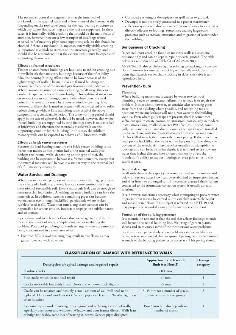
Soil Types The types of soils usually present under the topsoil in land zoned for residential buildings can be split into two approximate groups – granular and clay. Quite often, foundation soil is a mixture of both types. The general problems associated with soils having granular content are usually caused by erosion. Clay soils are subject to saturation and swell/shrink problems.Classifications for a given area can generally be obtained by application to the local authority, but these are sometimes unreliable and if there is doubt, a geotechnical report should be commissioned. As most buildings suffering movement problems are founded on clay soils, there is an emphasis on classification of soils according to the amount of swell and shrinkage they experience with variations of water content. The table below is Table 2.1 from AS 2870-2011, the Residential Slab and Footing Code.
Causes of Movement
Settlement due to construction There are two types of settlement that occur as a result of construction: • Immediate settlement occurs when a building is first placed
on its foundation soil, as a result of compaction of the soil underthe weight of the structure. The cohesive quality of clay soilmitigates against this, but granular (particularly sandy) soil issusceptible.
• Consolidation settlement is a feature of clay soil and may takeplace because of the expulsion of moisture from the soil or becauseof the soil’s lack of resistance to local compressive or shear stresses.This will usually take place during the first few months afterconstruction, but has been known to take many years inexceptional cases.
These problems are the province of the builder and should be taken into consideration as part of the preparation of the site for construction. Building Technology File 19 (BTF 19) deals with these problems.
ErosionAll soils are prone to erosion, but sandy soil is particularly susceptible to being washed away. Even clay with a sand component of say 10% or more can suffer from erosion.
SaturationThis is particularly a problem in clay soils. Saturation creates a bog- like suspension of the soil that causes it to lose virtually all of its bearing capacity. To a lesser degree, sand is affected by saturation because saturated sand may undergo a reduction in volume, particularly imported sand fill for bedding and blinding layers. However, this usually occurs as immediate settlement and should normally be the province of the builder.
Seasonal swelling and shrinkage of soil All clays react to the presence of water by slowly absorbing it, making the soil increase in volume (see table below). The degree of increase varies considerably between different clays, as does the degree of decrease during the subsequent drying out caused by fair weather periods. Because of the low absorption and expulsion rate, this phenomenon will not usually be noticeable unless there are prolonged rainy or dry periods, usually of weeks or months, depending on the land and soil characteristics. The swelling of soil creates an upward force on the footings of the building, and shrinkage creates subsidence that takes away the support needed by the footing to retain equilibrium.
Shear failure This phenomenon occurs when the foundation soil does not have sufficient strength to support the weight of the footing. There are two major post-construction causes:
• Significant load increase.• Reduction of lateral support of the soil under the footing due to
erosion or excavation.
In clay soil, shear failure can be caused by saturation of the soil adjacent to or under the footing.
GENERAL DEFINITIONS OF SITE CLASSES
Class Foundation
A Most sand and rock sites with little or no ground movement from moisture changes
S Slightly reactive clay sites, which may experience only slight ground movement from moisture changes
M Moderately reactive clay or silt sites, which may experience moderate ground movement from moisture changes
H1 Highly reactive clay sites, which may experience high ground movement from moisture changes
H2 Highly reactive clay sites, which may experience very high ground movement from moisture changes
E Extremely reactive sites, which may experience extreme ground movement from moisture changesNotes1. Where controlled fill has been used, the site may be classified A to E according to the type of fill used.2. Filled sites. Class P is used for sites which include soft fills, such as clay or silt or loose sands; landslip; mine subsidence; collapsing soils; soil subject to erosion;
reactive sites subject to abnormal moisture conditions or sites which cannot be classified otherwise.3. Where deep-seated moisture changes exist on sites at depths of 3 m or greater, further classification is needed for Classes M to E (M-D, H1-D, H2-D and E-D).
BTF 18-2011replaces
Information Sheet 10/91
081203 BTF 18 3pp.indd 1 25/10/12 12:40:29

Tree root growthTrees and shrubs that are allowed to grow in the vicinity of footings can cause foundation soil movement in two ways: • Roots that grow under footings may increase in cross-sectional
size, exerting upward pressure on footings.• Roots in the vicinity of footings will absorb much of the moisture
in the foundation soil, causing shrinkage or subsidence.
Unevenness of MovementThe types of ground movement described above usually occur unevenly throughout the building’s foundation soil. Settlement due to construction tends to be uneven because of: • Differing compaction of foundation soil prior to construction.• Differing moisture content of foundation soil prior to
construction.
Movement due to non-construction causes is usually more uneven still. Erosion can undermine a footing that traverses the flow or can create the conditions for shear failure by eroding soil adjacent to a footing that runs in the same direction as the flow. Saturation of clay foundation soil may occur where subfloor walls create a dam that makes water pond. It can also occur wherever there is a source of water near footings in clay soil. This leads to a severe reduction in the strength of the soil which may create local shear failure. Seasonal swelling and shrinkage of clay soil affects the perimeter of the building first, then gradually spreads to the interior. The swelling process will usually begin at the uphill extreme of the building, or on the weather side where the land is flat. Swelling gradually reaches the interior soil as absorption continues. Shrinkage usually begins where the sun’s heat is greatest.
Effects of Uneven Soil Movement on Structures
Erosion and saturation Erosion removes the support from under footings, tending to create subsidence of the part of the structure under which it occurs. Brickwork walls will resist the stress created by this removal of support by bridging the gap or cantilevering until the bricks or the mortar bedding fail. Older masonry has little resistance. Evidence of failure varies according to circumstances and symptoms may include: • Step cracking in the mortar beds in the body of the wall or above/
below openings such as doors or windows.• Vertical cracking in the bricks (usually but not necessarily in line
with the vertical beds or perpends).
Isolated piers affected by erosion or saturation of foundations will eventually lose contact with the bearers they support and may tilt or fall over. The floors that have lost this support will become bouncy, sometimes rattling ornaments etc.
Seasonal swelling/shrinkage in clay Swelling foundation soil due to rainy periods first lifts the most exposed extremities of the footing system, then the remainder of the perimeter footings while gradually permeating inside the building footprint to lift internal footings. This swelling first tends to create a dish effect, because the external footings are pushed higher than the internal ones. The first noticeable symptom may be that the floor appears slightly dished. This is often accompanied by some doors binding on the floor or the door head, together with some cracking of cornice mitres. In buildings with timber flooring supported by bearers and joists, the floor can be bouncy. Externally there may be visible dishing of the hip or ridge lines. As the moisture absorption process completes its journey to the innermost areas of the building, the internal footings will rise. If the spread of moisture is roughly even, it may be that the symptoms will temporarily disappear, but it is more likely that swelling will be uneven, creating a difference rather than a disappearance in symptoms. In buildings with timber flooring supported by bearers and joists, the isolated piers will rise more easily than the strip footings or piers under walls, creating noticeable doming of flooring. As the weather pattern changes and the soil begins to dry out, the external footings will be first affected, beginning with the locations where the sun’s effect is strongest. This has the effect of lowering the
external footings. The doming is accentuated and cracking reduces or disappears where it occurred because of dishing, but other cracks open up. The roof lines may become convex. Doming and dishing are also affected by weather in other ways. In areas where warm, wet summers and cooler dry winters prevail, water migration tends to be toward the interior and doming will be accentuated, whereas where summers are dry and winters are cold and wet, migration tends to be toward the exterior and the underlying propensity is toward dishing.
Movement caused by tree roots In general, growing roots will exert an upward pressure on footings, whereas soil subject to drying because of tree or shrub roots will tend to remove support from under footings by inducing shrinkage.
Complications caused by the structure itself Most forces that the soil causes to be exerted on structures are vertical – i.e. either up or down. However, because these forces are seldom spread evenly around the footings, and because the building resists uneven movement because of its rigidity, forces are exerted from one part of the building to another. The net result of all these forces is usually rotational. This resultant force often complicates the diagnosis because the visible symptoms do not simply reflect the original cause. A common symptom is binding of doors on the vertical member of the frame.
Effects on full masonry structures Brickwork will resist cracking where it can. It will attempt to span areas that lose support because of subsided foundations or raised points. It is therefore usual to see cracking at weak points, such as openings for windows or doors. In the event of construction settlement, cracking will usually remain unchanged after the process of settlement has ceased. With local shear or erosion, cracking will usually continue to develop until the original cause has been remedied, or until the subsidence has completely neutralised the affected portion of footing and the structure has stabilised on other footings that remain effective. In the case of swell/shrink effects, the brickwork will in some cases return to its original position after completion of a cycle, however it is more likely that the rotational effect will not be exactly reversed, and it is also usual that brickwork will settle in its new position and will resist the forces trying to return it to its original position. This means that in a case where swelling takes place after construction and cracking occurs, the cracking is likely to at least partly remain after the shrink segment of the cycle is complete. Thus, each time the cycle is repeated, the likelihood is that the cracking will become wider until the sections of brickwork become virtually independent. With repeated cycles, once the cracking is established, if there is no other complication, it is normal for the incidence of cracking to stabilise, as the building has the articulation it needs to cope with the problem. This is by no means always the case, however, and monitoring of cracks in walls and floors should always be treated seriously. Upheaval caused by growth of tree roots under footings is not a simple vertical shear stress. There is a tendency for the root to also exert lateral forces that attempt to separate sections of brickwork after initial cracking has occurred.
Trees can cause shrinkage and damage
Wall crackingdue to unevenlooting settlement
081203 BTF 18 3pp.indd 2 25/10/12 12:40:49
The normal structural arrangement is that the inner leaf of brickwork in the external walls and at least some of the internal walls (depending on the roof type) comprise the load-bearing structure on which any upper floors, ceilings and the roof are supported. In these cases, it is internally visible cracking that should be the main focus of attention, however there are a few examples of dwellings whose external leaf of masonry plays some supporting role, so this should be checked if there is any doubt. In any case, externally visible cracking is important as a guide to stresses on the structure generally, and it should also be remembered that the external walls must be capable of supporting themselves.
Effects on framed structures Timber or steel framed buildings are less likely to exhibit cracking due to swell/shrink than masonry buildings because of their flexibility. Also, the doming/dishing effects tend to be lower because of the lighter weight of walls. The main risks to framed buildings are encountered because of the isolated pier footings used under walls. Where erosion or saturation causes a footing to fall away, this can double the span which a wall must bridge. This additional stress can create cracking in wall linings, particularly where there is a weak point in the structure caused by a door or window opening. It is, however, unlikely that framed structures will be so stressed as to suffer serious damage without first exhibiting some or all of the above symptoms for a considerable period. The same warning period should apply in the case of upheaval. It should be noted, however, that where framed buildings are supported by strip footings there is only one leaf of brickwork and therefore the externally visible walls are the supporting structure for the building. In this case, the subfloor masonry walls can be expected to behave as full brickwork walls.
Effects on brick veneer structures Because the load-bearing structure of a brick veneer building is the frame that makes up the interior leaf of the external walls plus perhaps the internal walls, depending on the type of roof, the building can be expected to behave as a framed structure, except that the external masonry will behave in a similar way to the external leaf of a full masonry structure.
Water Service and Drainage Where a water service pipe, a sewer or stormwater drainage pipe is in the vicinity of a building, a water leak can cause erosion, swelling or saturation of susceptible soil. Even a minuscule leak can be enough to saturate a clay foundation. A leaking tap near a building can have the same effect. In addition, trenches containing pipes can become watercourses even though backfilled, particularly where broken rubble is used as fill. Water that runs along these trenches can be responsible for serious erosion, interstrata seepage into subfloor areas and saturation. Pipe leakage and trench water flows also encourage tree and shrub roots to the source of water, complicating and exacerbating the problem. Poor roof plumbing can result in large volumes of rainwater being concentrated in a small area of soil: • Incorrect falls in roof guttering may result in overflows, as may
gutters blocked with leaves etc.
• Corroded guttering or downpipes can spill water to ground.• Downpipes not positively connected to a proper stormwater
collection system will direct a concentration of water to soil that isdirectly adjacent to footings, sometimes causing large-scaleproblems such as erosion, saturation and migration of water underthe building.
Seriousness of Cracking In general, most cracking found in masonry walls is a cosmetic nuisance only and can be kept in repair or even ignored. The table below is a reproduction of Table C1 of AS 2870-2011. AS 2870-2011 also publishes figures relating to cracking in concrete floors, however because wall cracking will usually reach the critical point significantly earlier than cracking in slabs, this table is not reproduced here.
Prevention/Cure
PlumbingWhere building movement is caused by water service, roof plumbing, sewer or stormwater failure, the remedy is to repair the problem. It is prudent, however, to consider also rerouting pipes away from the building where possible, and relocating taps to positions where any leakage will not direct water to the building vicinity. Even where gully traps are present, there is sometimes sufficient spill to create erosion or saturation, particularly in modern installations using smaller diameter PVC fixtures. Indeed, some gully traps are not situated directly under the taps that are installed to charge them, with the result that water from the tap may enter the backfilled trench that houses the sewer piping. If the trench has been poorly backfilled, the water will either pond or f low along the bottom of the trench. As these trenches usually run alongside the footings and can be at a similar depth, it is not hard to see how any water that is thus directed into a trench can easily affect the foundation’s ability to support footings or even gain entry to the subfloor area.
Ground drainage In all soils there is the capacity for water to travel on the surface and below it. Surface water flows can be established by inspection during and after heavy or prolonged rain. If necessary, a grated drain system connected to the stormwater collection system is usually an easy solution. It is, however, sometimes necessary when attempting to prevent water migration that testing be carried out to establish watertable height and subsoil water flows. This subject is referred to in BTF 19 and may properly be regarded as an area for an expert consultant.
Protection of the building perimeter It is essential to remember that the soil that affects footings extends well beyond the actual building line. Watering of garden plants, shrubs and trees causes some of the most serious water problems. For this reason, particularly where problems exist or are likely to occur, it is recommended that an apron of paving be installed around as much of the building perimeter as necessary. This paving should
CLASSIFICATION OF DAMAGE WITH REFERENCE TO WALLS
Description of typical damage and required repairApproximate crack width
limit (see Note 3)Damage category
Hairline cracks <0.1 mm 0
Fine cracks which do not need repair <1 mm 1
Cracks noticeable but easily filled. Doors and windows stick slightly. <5 mm 2
Cracks can be repaired and possibly a small amount of wall will need to be replaced. Doors and windows stick. Service pipes can fracture. Weathertightness often impaired.
5–15 mm (or a number of cracks 3 mm or more in one group)
3
Extensive repair work involving breaking-out and replacing sections of walls, especially over doors and windows. Window and door frames distort. Walls lean or bulge noticeably, some loss of bearing in beams. Service pipes disrupted.
15–25 mm but also depends on number of cracks
4
081203 BTF 18 3pp.indd 3 25/10/12 12:41:09
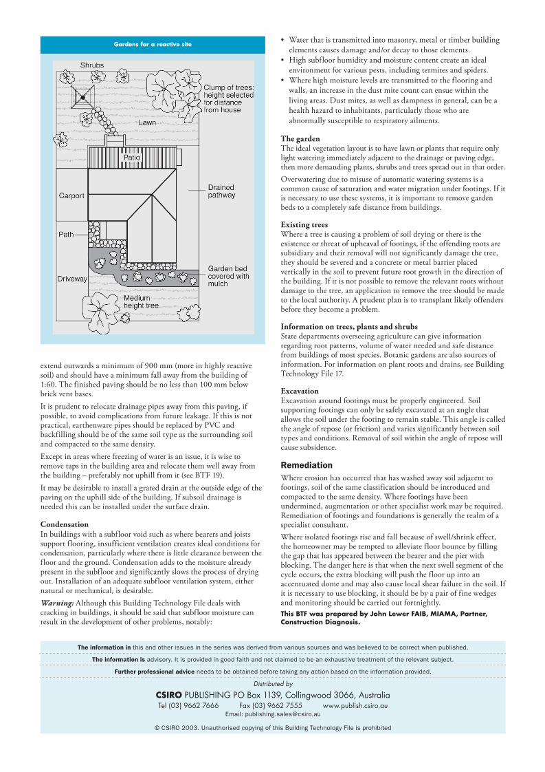
extend outwards a minimum of 900 mm (more in highly reactive soil) and should have a minimum fall away from the building of 1:60. The finished paving should be no less than 100 mm below brick vent bases. It is prudent to relocate drainage pipes away from this paving, if possible, to avoid complications from future leakage. If this is not practical, earthenware pipes should be replaced by PVC and backfilling should be of the same soil type as the surrounding soil and compacted to the same density. Except in areas where freezing of water is an issue, it is wise to remove taps in the building area and relocate them well away from the building – preferably not uphill from it (see BTF 19). It may be desirable to install a grated drain at the outside edge of the paving on the uphill side of the building. If subsoil drainage is needed this can be installed under the surface drain.
CondensationIn buildings with a subfloor void such as where bearers and joists support flooring, insufficient ventilation creates ideal conditions for condensation, particularly where there is little clearance between the floor and the ground. Condensation adds to the moisture already present in the subfloor and significantly slows the process of drying out. Installation of an adequate subfloor ventilation system, either natural or mechanical, is desirable. Warning: Although this Building Technology File deals with cracking in buildings, it should be said that subfloor moisture can result in the development of other problems, notably:
• Water that is transmitted into masonry, metal or timber buildingelements causes damage and/or decay to those elements.
• High subfloor humidity and moisture content create an idealenvironment for various pests, including termites and spiders.
• Where high moisture levels are transmitted to the flooring andwalls, an increase in the dust mite count can ensue within theliving areas. Dust mites, as well as dampness in general, can be ahealth hazard to inhabitants, particularly those who areabnormally susceptible to respiratory ailments.
The gardenThe ideal vegetation layout is to have lawn or plants that require only light watering immediately adjacent to the drainage or paving edge, then more demanding plants, shrubs and trees spread out in that order. Overwatering due to misuse of automatic watering systems is a common cause of saturation and water migration under footings. If it is necessary to use these systems, it is important to remove garden beds to a completely safe distance from buildings.
Existing trees Where a tree is causing a problem of soil drying or there is the existence or threat of upheaval of footings, if the offending roots are subsidiary and their removal will not significantly damage the tree, they should be severed and a concrete or metal barrier placed vertically in the soil to prevent future root growth in the direction of the building. If it is not possible to remove the relevant roots without damage to the tree, an application to remove the tree should be made to the local authority. A prudent plan is to transplant likely offenders before they become a problem.
Information on trees, plants and shrubs State departments overseeing agriculture can give information regarding root patterns, volume of water needed and safe distance from buildings of most species. Botanic gardens are also sources of information. For information on plant roots and drains, see Building Technology File 17.
ExcavationExcavation around footings must be properly engineered. Soil supporting footings can only be safely excavated at an angle that allows the soil under the footing to remain stable. This angle is called the angle of repose (or friction) and varies significantly between soil types and conditions. Removal of soil within the angle of repose will cause subsidence.
RemediationWhere erosion has occurred that has washed away soil adjacent to footings, soil of the same classification should be introduced and compacted to the same density. Where footings have been undermined, augmentation or other specialist work may be required. Remediation of footings and foundations is generally the realm of a specialist consultant. Where isolated footings rise and fall because of swell/shrink effect, the homeowner may be tempted to alleviate floor bounce by filling the gap that has appeared between the bearer and the pier with blocking. The danger here is that when the next swell segment of the cycle occurs, the extra blocking will push the floor up into an accentuated dome and may also cause local shear failure in the soil. If it is necessary to use blocking, it should be by a pair of fine wedges and monitoring should be carried out fortnightly. This BTF was prepared by John Lewer FAIB, MIAMA, Partner, Construction Diagnosis.
The information in this and other issues in the series was derived from various sources and was believed to be correct when published.
The information is advisory. It is provided in good faith and not claimed to be an exhaustive treatment of the relevant subject.
Further professional advice needs to be obtained before taking any action based on the information provided.
Distributed by
CSIRO PUBLISHING PO Box 1139, Collingwood 3066, AustraliaTel (03) 9662 7666 Fax (03) 9662 7555 www.publish.csiro.au
Email: [email protected]
© CSIRO 2003. Unauthorised copying of this Building Technology File is prohibited
Gardens for a reactive site
081203 BTF 18 3pp.indd 4 25/10/12 12:41:26