o.. technical library
TRANSCRIPT
A0V\03?f6^ - RIA-77-U931 AD
o..
FA-TR-76067
Production Engineering Measures Program Manufacturing Methods and Technology Project Number 5726335
TECHNICAL LIBRARY
| Program to Develop High Strength Aluminum Powder Metallurgy Mill Products
Phase IVB — Scale — up to 1545 kg (3400 lb.) Billet
1977 April 25
Final Report on Contract Number DAAA 25-72-C-0593
Approved For Public Release; Distribution Unlimited
W. 8. Cebulak Aluminum Company of America Alcoa Technical Center Alcoa Center, PA 15069
U.S. ARMY ARMAMENT COMMAND FRAN KFORD ARSENAL
PHILADELPHIA, PENNSYLVANIA 19137
DISPOSITION INSTRUCTIONS
Destroy this report when it is no longer needed. Do not return it to the originator.
The findings in this report are not to be construed as an official Department of the Army position, unless so designated by other author- ized documents.
Mention of any trade names or manufacturers in this report shall not be construed as advertising nor as an official indorsement or approval of such products or companies by the United States Government.
This project was accomplished as part of the U.S. Army manufacturing technology program. The primary objective of this program is to develop, on a timely basis, manufacturing processes, techniques, and equipment for use in production of Army material. Manufacturing Methods and Technology Project Number 5726335.
UNCLASSIFIED SECUPilTY CLASSIFICATION OF THIS PAGE (Whan Deta Entsred)
REPORT DOCUMENTATION PAGE READ INSTRUCTIONS BEFORE COMPLETING FORM
REPORT NUMBER
FFA Report No. FA-TR-76067
2. GOVT ACCESSION KG, 3. RECIPIENT'S CATALOG NUMBER
TITLE (and Subtitle)
Program to Develop High Strength Aluminum Powder Metallurgy Mill Products - Phase IV-B-Scale - uj to 3200 lb Billet
S. TYPE OF REPORT & PERIOD COVERED
Final Report June 1972 - Feb 1976
6. PERFORMING ORG. REPORT NUMBER
7. AUTHORri
W. S. Cebulak
B- CONTRACT OR GRANT NUMBER^;
DAAA25-72-C-0593
PERFORMING ORGANIZATION NAME AND ADDRESS
Aluminum Company of America Alcoa Technical Center Alcoa Center, PA 15069
CONTROLLING OFFICE NAME AND ADDRESS
U. S. Army Armament Command Rock Island, IL 61201
10. PROGRAM ELEMENT, PROJECT, TASK AREA « WORK UNIT NUMBERS
MM&T Project No. 5726335-
12. REPORT DATE'
April 25, 1977 13. NUMBER OF PAGES
133 MONITORING AGENCY NAME a ADDRESSf// dltferent from Controltina Office)
Frankford Arsenal Bridge & Tacony Sts. Philadelphia, PA 19137
15. SECURITY CLASS, (of this report)
u ISa. DECLASSIFI CATION/DOWN GRADING
SCHEDULE
16. DISTRIBUTION STATEMENT fo/(Ws ReporO
Approved for Public Release; Distribution Unlimited
17. DISTRIBUTION STATEMENT (of the abstract entered in Block 20, If different from Report)
la. SUPPLEMENTARY NOTES
:'. ?*) KEY WORDS (Continue on reverse side if necessary and identify by block number)
I Aluminum, Aluminum Powder Metallurgy, Scale-Up, P/M 7XXX Alloys, Plate, j Extrusions, Forgings, P/M Processing, Fracture Toughness, Stress Corrosion, Fatigue
f— rSSTRACT (Continue on reverse side it necessary and Identify by block number)
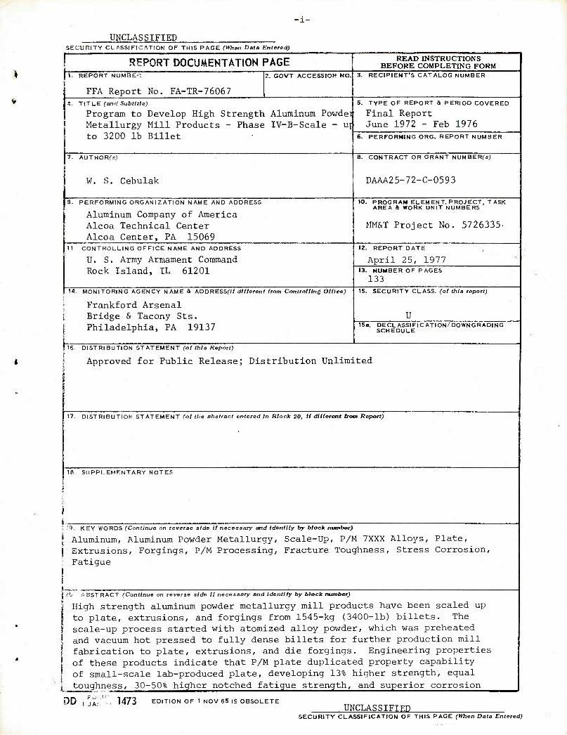
High strength aluminum powder metallurgy mill products have been scaled up to plate, extrusions, and forgings from 1545-kg (3400-lb) billets. The scale-up process started with atomized alloy powder, which was preheated and vacuum hot pressed to fully dense billets for further production mill fabrication to plate, extrusions, and die forgings. Engineering properties of these products indicate that P/M plate duplicated property capability of small-scale lab-produced plate, developing 13% higher strength, equal toughness, 30-50% higher notched fatigue strength, and superior corrosion
DD 1473 EDITION OF 1 NOV 65 IS OBSOLETE UNCLASSIFIED
SECURITY CLASSIFICATION OF THIS PAGE fHTien Data Entered)
-11-
SECURITY CLASSIFICATION OF THIS PAGEfWlan Data Bntend)
20. Continued
and stress corrosion compared to existing commercial I/M alloys. Scaled-up P/M extrusions and die forgings were weaker than earlier, lab-scale products but still developed superior stress corrosion resistance and 30 to 80% higher notched fatigue strength compared to existing commercial alloys. An Alcoa-funded follow-on study is in progress to develop billet processing and product fabrication variations leading to duplicating properties of lab-scale P/M products for all billet sizes and all products. A report on that study will be distributed when completed.
SECURITY CLASSIFICATION OF THIS PAGEflfhen Data Entered)
■
-111-
FOREWORD
The Aluminum Company of America, Alcoa Technical Center, Alcoa Center, PA 15069, prepared this report to satisfy the requirements of Contract DAAA25-72-C-0593. This project was accomplished as part of the U. S. Army manufacturing technology program. The primary objective of this program is to develop, on a timely basis, manufacturing processes, techniques and equipment for use in production of Army material. The project number of this project is 5726335.
The Alcoa Project Engineer for this program was Walter S. Cebulak, with Joseph H. Dudas and J. Paul Lyle, Jr. as project supervisors. The Frankford Arsenal Project Engineer was Dr. Jeffrey Waldman.
-iv-
TABLE OF CONTENTS
INTRODUCTION
I. SCALE-UP PROCESS DEVELOPMENT
A. Tooling and Equipment Fabrication
Isostatic Pressing Vibratory Packing Development Powder Handling for Preheating Vacuum Systems Hot Compacting Tools Die Heating System
B. First Experimental Preheat and Hot Press System Trial
Vacuum System Checkout Die and Powder Heat-Up Compacting Die Installation in the Press Vacuum Sealing for Hot Pressing P/M Billet Hot Pressing
Modifications for Further Process Development . . . .
C. Second Experimental Preheat and Billet Hot Pressing - May 1975
Powder and Die Preheating First Billet Pressing Operation Further Billet Generation
D. Fabrication of Mill Products
Plate Extrusions Die Forgings
II. PROPERTIES OF PRODUCTION-FABRICATED P/M MILL PRODUCTS .
A. Plate
B. Extrusions
C. Forgings
D. Summary of Properties of Mill Products from 1545-kg (3400-lb) Billets
III. CONCLUSIONS AND RECOMMENDATIONS FOR APPLICATION OF THIS DEVELOPMENT
A. Conclusions
PAGE NO.
1
1
1
1 3 3 4 5 6
7 7 8 9
10 10
12
12 12 14
16
16 17 17
18
18
20
23
24
25
25
-v-
TABLE OF CONTENTS (CONTINUED)
PAGE NO.
1. Process 25 2. Properties 26
B. Recommendations . . . .' 27
1. Further Process Development 27 2. Further Property and Product Development 28 3. Application Evaluations 29
REFERENCES 30
FIGURES
TABLES
DISTRIBUTION LIST
LIST OF ILLUSTRATIONS
FIGURE 1 - Laboratory-Scale P/M Process
FIGURE 2 - Isostatic Compacting Tools Above 152-cm Diameter Isostatic Vessel
FIGURE 3 - Schematic of Powder Loading System
FIGURE 4 - 1409-kg {3100-lb) MA87 Alloy Isostatic Compact
FIGURE 5 - Scale-Up P/M Process
FIGURE 6 - Schematic of Powder Preheat Container
FIGURE 7 - Inside of Preheat Container Lid Showing Welded-In Porous Stainless Steel Filter
FIGURE 8 - Preheat Container Powder Loading System
FIGURE 9 - Complete Powder Preheat and Evacuation Container
FIGURE 10 - Schematic of Vacuum Preheat Operation
FIGURE 11 - Assembled Vacuum Pumps Showing Connections to Under-Car Evaucation System
FIGURE 12 - Vacuum Pump Connected to Furnace and Under-Car Evacuation System
FIGURE 13 - Evacuation-Line Pinch Off Tool Assembly
FIGURE 14 - Schematic of Hot Compacting Tools for 1545-kg (3400-lb) Billet
-vi-
LIST OF ILLUSTRATIONS (CONTINUED)
FIGURE 15 - Compacting Cylinder Liner and Outer Container
FIGURE 16 - Ram Nose Piece; Densification Ram; Ram Holder
FIGURE 17 - Top and Bottom Hard Plates to Secure Tools to Press Platens
FIGURE 18 - Bottom Seal for Hot Compacting Cylinder
FIGURE 19 - Assembled Hot Compacting Tools
FIGURE 20 - Portable Die Heater for Preheating Compacting Cylinder and Ram Assembly
FIGURE 21 - Die Heater Furnace Lid
FIGURE 22 - Die Heater Frame with Installed Panel Burners
FIGURE 23 - Hot Compacting Die Heating Rate - December 1974
FIGURE 24 - Heating Lower Base Plate - Cylinder Seal Assembly
FIGURE 25 - Vacuum Heat-up Rate for Powder and Containers - December 1974
FIGURE 26 - Lowering Base of Lower Seal Assembly to Lower Platen of Press to Initiate Tool Installation in 311-MN (35,000-ton) Press
FIGURE 27 - Lifting Die Heater Furnace Lid from Furnace Frame
FIGURE 28 - Lifting Ram Assembly from Die Heater
FIGURE 29 - Lifting Die Heater from Around Hot Compacting Cylinder
FIGURE 30 - Hot Compacting Cylinder Being Lowered to the Bottom Seal
FIGURE 31 - Base Plate, Cylinder, and Ram Assembly Being Transported into the Press
FIGURE 32 - Hot Compacting Cylinder and Ram Assembly in 311-MN (35,000-ton) Press
FIGURE 33 - Vacuum Level During Preheating of December 1974 Trial Samples
FIGURE 34 - Weld-Sealing Evacuation Line Prior to Hot Pressing - Sample 354114
FIGURE 35 - Evacuated Powder Container Being Loaded in Hot Compacting Cylinder
-Vll-
LIST OF ILLUSTRATIONS (CONTINUED)
FIGURE 36 - Aluminum Flash Extruded Past Bottom Cylinder Seal on East Side of Press
FIGURE 37 - Aluminum Flash Extruded Past Bottom Cylinder Seal on West Side of Press
FIGURE 38 - Schematic of Sealing Ring Application
FIGURE 39 - Powder Heat-Up Rate for May 1975 Trial Sample
FIGURE 40 - Powder Preheat Containers with Evacuation Line Being Pinched Closed Prior to Weld-Sealing
FIGURE 41 - Ejected Billet Under Suspended Cylinder
FIGURE 42 - Vacuum Pump and Furnace Car Assembly with Three Powder Containers for Preheating
FIGURE 43 - Arrangement of Powder Containers in Furnaces for Preheating
FIGURE 44 - Heat-Up Rate for Powder Containers in Furnace 3
FIGURE 45 - Heat-Up Rate for Powder Containers in Furnace 4
FIGURE 46 - Scalped and Etched Hot Pressed Compacts
FIGURE 47 - Draw Forging Operation for Billets
FIGURE 48 - Forged P/M MA87 Slab to be Rolled to 5-cm (2-in.) Plate
FIGURE 49 - Alcoa Section 263902
FIGURE 50 - Forging from Die No. 12767
FIGURE 51 - Effect of Yield Strength on Fracture Toughness of P/M MA87 - 5-cm (2-in.) Thick Plate
FIGURE 52 - Effect of Strength on Stress Corrosion Performance of P/M MA87 - 5-cm (2-in.) Thick Plate
FIGURE 53 - Notched Specimen Fatigue Performance of P/M MA87 - 5-cm (2-in.) Thick Plate
FIGURE 54 - Smooth Specimen Fatigue Performance of P/M MA87 - 5-cm (2-in.) Thick Plate
FIGURE 55 - Effect of Yield Strength on Exfoliation Resistance of P/M MA87 - 5-cm (2-in.) Thick Plate
-Vlll-
LIST OF ILLUSTRATIONS (CONTINUED)
FIGURE 56 - Conductivity versus Yield Strength for P/M Extrusions
FIGURE 57 - Effect of Strength on Toughness of Extrusions
FIGURE 58 - Effect of Quench Rate on Transverse Fracture Toughness (NTS/YS) to Yield Strength Relation for MA88, MA89, and MA90 5-cin (2-in.) Diameter Extruded Rod
FIGURE 59 - Effect of Strength on Stress Corrosion Performance of P/M Extrusions
FIGURE 60 - Effect of Strength on Stress Corrosion Performance of P/M Extrusions - Section 263902
FIGURE 61 - Effect of Longitudinal Yield Strength on Exfoliation Resistance of P/M Extrusions - Section 263902
FIGURE 62 - Notched Specimen Axial Stress Fatigue Performance of P/M Extrusions from 1545-kg (3400-lb) Billets - Extrusion 263902 - All Specimens Longitudinal
FIGURE 63 - Smooth Specimen Axial Stress Fatigue Performance of P/M Extrusions from 1545-kg (3400-lb) Billets - Extrusion 263902 - All Specimens Longitudinal
FIGURE 64 - Effect of Yield Strength on Toughness of P/M Die 12767 Forgings from 1545-kg (3400-lb) Billets
FIGURE 65 - Effect of Strength and Stress of Stress Corrosion Performance of P/M Die Forgings from 1545-kg (3400-lb) Billets
LIST OF TABLES
TABLE 1 - Design Factors for Large-Scale Cold Isostatic Tooling
TABLE 2 - Composition and Powder Size for MA87 Powder for First 1409-kg (3100-lb) Isostatic Compact
TABLE 3 - Chemical Composition of Alloys Atomized for P/M Billets
TABLE 4 - Powder Size for Scale-Up Alloy - Powders
TABLE 5 - Powder and Container Weights for First Billet Pressing Operation
TABLE 6 - Steel Forgings Required for Hot Compacting Tools
TABLE 7 - Powder and Container Weights for Second Billet Pressing Operation
-ix-
LIST OF TABLES (CONTINUED)
TABLE 8 - Hot Rolling Schedule for P/M MA87 Plate
TABLE 9 - Tensile and Fracture Toughness of P/M MA87, 5-cm Thick Plate
TABLE 10 - Tensile and Fracture Toughness of P/M MA87, 2-in. Plate
TABLE 11 - Stress Corrosion and Exfoliation Performance of P/M MA87 Plate, 5-cm (2-in.) Thick from 1545-kg (3400-lb) Compacts
TABLE 12 - Notched Specimen Axial Stress Fatigue Performance of MA87, 5-cm (2-in.) Thick Plate
TABLE 13 - Smooth Specimen Axial Stress Fatigue Performance of MA87, 5-cm (2-in.) Thick Plate
TABLE 14 - Mechanical Properties of P/M Extrusions from 1545-kg Billet
TABLE 15 - Mechanical Properties of P/M Extrusions from 3400-lb Billet
TABLE 16 - Stress Corrosion and Exfoliation Corrosion Performance of P/M MA87 and MA67 Extrusions from 1545-kg (3400-lb) Compacts
TABLE 17 - Notched Specimen Axial Stress Fatigue Performance of P/M Extrusions
TABLE 18 - Smooth Specimen Axial Stress Fatigue Performance of P/M Extrusions
TABLE 19 - Effect of Reheat Treatment and Quench Geometry on Electrical Conductivity of T6 Temper Production-Scale P/M Extrusions
TABLE 20 - Strength and Conductivity of 5-cm (2-in.) Thick P/M Hand Forgings Aged to T6 Temper
TABLE 21 - Mechanical Properties of P/M MA87 and MA67 Die Forgings from 1545 kg Compacts
TABLE 22 - Mechanical Properties of P/M MA87 and MA67 Die Forgings from 3400-lb Compacts
TABLE 23 - Stress Corrosion Performance of P/M MA87 and MA67 Die Forgings from 1545-kg (3400-lb) Compacts
TABLE 24 - Comparison of Properties of P/M Forgings of Differing Geometric Configurations and from Different Billet Sizes
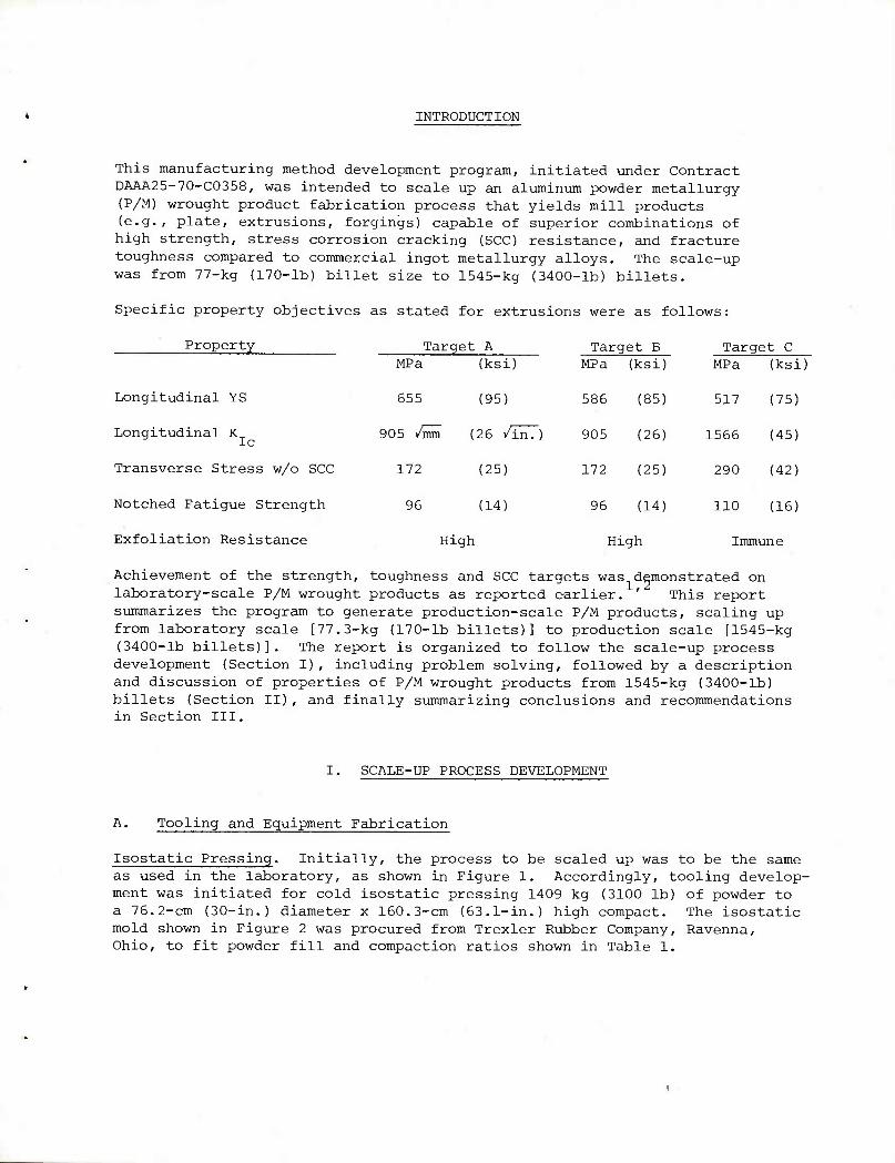
INTRODUCTION
This manufacturing method development program, initiated under Contract DAAA25-70-C0358, was intended to scale up an aluminum powder metallurgy (P/M) wrought product fabrication process that yields mill products (e.g., plate, extrusions, forgings) capable of superior combinations of high strength, stress corrosion cracking (SCO) resistance, and fracture toughness compared to commercial ingot metallurgy alloys. The scale-up was from 77-kg (170-lb) billet size to 1545-kg (3400-lb) billets.
Specific property objectives as stated for extrusions were as follows:
Property Target A
Longitudinal YS
Longitudinal K Ic
Transverse Stress w/o SCC
MPa (ksi)
655 (95)
905 /mm (26 /in.)
172 (25)
Target B MPa (ksi)
586 (85)
905 (26)
172 (25)
Target C MPa (ksi)
517 (75)
1566 (45)
290 (42)
Notched Fatigue Strength 96 (14) 96 (14; 110 (16)
Exfoliation Resistance High High Immune
Achievement of the strength, toughness and SCC targets was demonstrated on laboratory-scale P/M wrought products as reported earlier. ' This report summarizes the program to generate production-scale P/M products, scaling up from laboratory scale [77.3-kg (170-lb billets)] to production scale [1545-kg (3400-lb billets)]. The report is organized to follow the scale-up process development (Section I), including problem solving, followed by a description and discussion of properties of P/M wrought products from 1545-kg (3400-lb) billets (Section II), and finally summarizing conclusions and recommendations in Section III.
SCALE-UP PROCESS DEVELOPMENT
A. Tooling and Equipment Fabrication
Isostatic Pressing. Initially, the process to be scaled up was to be the same as used in the laboratory, as shown in Figure 1. Accordingly, tooling develop- ment was initiated for cold isostatic pressing 1409 kg (3100 lb) of powder to a 76.2-cm (30-in.) diameter x 160.3-cm (63.1-in.) high compact. The isostatic mold shown in Figure 2 was procured from Trexler Rubber Company, Ravenna, Ohio, to fit powder fill and compaction ratios shown in Table 1.
-2-
The powder of composition and powder size shown in Table 2 was atomized, scalped and loaded into the isostatic mold using a powder handling system shown in Figure 3. After the bag was filled, the top closure was installed and closed with screw-tightened clamps.
Isostatic pressing of this first trial piece was conducted in the high pressure laboratory at Applied Research Laboratory, Pennsylvania State University. This 152.4-cm (60-in.) diameter x 427-cm (14-ft) deep vessel can be pressurized to 110 MPa (16,000 psi). For this program, the filled mold in Figure 2 was cold isostatically pressed to 110 MPa, requiring 112 minutes for the vessel to be pumped to that pressure. Depressurization required 20 minutes to vent through a valve in the upper seal of the press.
After removing the assembly from the press, it was found that one of the two clamps sealing the top of the rubber bag had moved during compression and that the perforated form in the upper seal was askew from its starting position.
Upon removing the upper rubber seal to the isostatic bag, water was observed on top of an otherwise sound-appearing compact. Within 1-1/2 minutes, the water had soaked into the compact, leaving the compact surface dry, sound and at the temperature of the water.
The compact was resealed and packed for transportation to Alcoa Technical Center for further inspection and encapsulation for vacuum preheating as the first trial piece.
Inspection of the compact on the next day showed that the water that leaked past the isostatic bag seals was reacting with the aluminum in the compact, heating the compact to 820C (180°F), resulting in severe cracking of the compact. This compact is shown in Figure 4.
While the probable cause for this water leak was not exactly pinpointed, it was felt that a partial vacuum (generated under the upper cylinder seal as it was lifted from the cylinder) lifted the top rubber seal from the main isostatic rubber container to allow air in the bag to escape to the vacuum. This opening then allowed water to enter the isostatic container when atmospheric pressure was restored.
This compact achieved 69-71% of theoretical density in cold isostatic pressing at 110 MPa, indicating that the compact would be relatively fragile to handle.
After encountering this problem with sealing of large cold isostatic rubber molds, consideration of alternate approaches to powder handling began. Since a green compact would require encapsulation for vacuum preheating, one possible alternative was to abandon the cold compacting step completely and directly encapsulate powder in the vacuum preheat container. This procedure would eliminate the development work required for cold isostatic compaction and would eliminate one step in the production operation, potentially decreasing the cost of the end product.
-3-
In earlier work with 9.1-kg (20-lb) billets, the fracture toughness achieved for extrusions from vacuum preheated and vacuum hot pressed powder was comparable to the fracture toughness of extrusions made from vacuum preheated and vacuum hot pressed isostatic compacts. Accordingly, we elected to proceed with development of a revised process,, summarized in Figure 5, which deleted cold compacting and substituted encapsulation of the atomized powder for preheating and hot pressing.
Vibratory Packing Development. One difficulty with this alternative was that the hot compacting tools had been designed and were being constructed for a 70% dense powder compact of 0.721 m (44,000 cu in.), while as-atomized powder has an apparent density of 45% of theoretical density. This lower density would mean that the hot compacting tools as designed could make only a 909-kg (2000- lb) billet. To raise the metal weight in the vacuum preheat container, vibratory compaction was investigated to raise the powder density.
Early trials to develop a vibratory packing procedure used 9.1-kg (20-lb) charges in 15.2-cm (6-in.) welded aluminum cans and a small air-driven turbine vibrator. Densities of 55 to 59% of theoretical density were achieved with MA87 alloy powder. Based on these results, a large turbine vibrator was incorporated in a fixture that would be used for vibratory compacting of loose powder in the welded aluminum container used for vacuum preheating. On the basis of these results, the atomization of alloy powders was initiated for fabrication of the large hot pressed P/M billets.
Powder Handling for Preheating. The alloys listed in Table 3 were melted and atomized to the powder sizes shown in Table 4 for vibratory compaction in vacuum preheat containers.
The vacuum can shown in Figure 6 was designed to fit the hot compacting cylinder and maximize the weight of powder for vibratory compaction and hot pressing in the tooling designed for the 1545-kg (3400-lb) billet scale-up. It was esti- mated that vibratory packing would result in 1318 kg (2900 lb) of powder in this can. The can incorporated a 5-cm (2-in.) aluminum evacuation line with a porous stainless steel filter over the inside evacuation line opening to prevent sucking powder into the vacuum equipment. Vibration was used during the entire period of powder loading to maximize the density achieved within each container. The preheat containers for handling of the atomized aluminum powder were welded 3003 alloy containers, 80 cm (31.5 in.) OD x 168.9 cm (66.5 in.) high, fabricated from 0.63-cm (1/4-in.) thick 3003 alloy plate for the side walls and 1.27-cm (1/2-in.) thick 3003 plate for the end plates. All seams on these containers were double welded to insure vacuum-tight construction. The cans were made by rolling and welding the outside wall and then welding in place the 1.27-cm (1/2-in.) thick bottom plate, completing the initial can assembly. The upper lid had a 5-cm (2-in.) diameter hole drilled in the plate and an evacuation line welded to one surface. A porous stainless steel filter was welded to the other surface of this top plate on the underside of the hole used for the evacuation line. Also welded to the top surface of this plate were three
-4-
bent 2.5-cin (1-in.) diameter aluminum rods which were used to lift the can into the hot compacting tools at the completion of the preheat operation. The actual position of the porous stainless steel filter is shown in Figure 7.
The atomized powders described in Tables 3 and 4 were loaded into the preheat containers with the aid of a vibratory packing fixture in the system shown in Figure 8.
Since powder atomized in small quantitites is handled in 0.208 m3 (55-gallon) drums, a manual packing procedure was devised for handling the limited number of cans to be processed for this program. The air-operated turbine vibrator on the vibratory packing fixture was operated continuously during the powder filling operation. The actual filling operation required the initial purging of the powder preheat container with nitrogen gas to eliminate any explosive hazard associated with this fine atomized aluminum powder. After purging, powder was admitted into the preheat container through a manually operated iris valve underneath the 0.208 m (55-gallon) drum. The powder flow rate into the preheat container was controlled to minimize dust emissions through any of the seals in the complete assembly. A gas bypass line allowed the displaced gas in the preheat container to travel from above the powder bed in the can to the bottom of the 0.208 m (55-gallon) drum, maintaining a closed- loop gas displacement in this complete assembly. Dust emissions in this closed system were minimized.
With the application of vibration in the powder loading operation, density in the preheat container fell within the range from 55 to 58% of theoretical density in the container. This can be compared to approximately 45% of theoretical density for the loose atomized powder. The actual weight of powder packed into each container is listed in Table 5.
After the cans were loaded, the upper can end was welded to the loaded can. The top lid was fitted into the ID of the can so that there was 0.6 cm (1/4 in.) of the top lid exposed outside of the can. Prior to initiation of welding, nitrogen was forced into the can through the evacuation opening to purge the plenum above the packed powder bed of oxygen and minimize any hazard associated with welding near atomized powder. This nitrogen flow was maintained throughout the welding operation to minimize any combustion hazard. Upon completion of the welding of these containers, containers were pressure-leak checked to verify the absence of any potential vacuum leaks. The completed cans were packed and shipped to Alcoa's Cleveland (Ohio) Works for assembly onto the preheat systems. A completed can is shown in Figure 9.
Vacuum Systems. The preheat system was designed for three vacuum containers connected in parallel to a vacuum pump system consisting of a 25.4-cm (10-in.) ring jet booster pump backed up by a Stokes Model 412H mechanical pump.
The vacuum system shown schematically in Figure 10 was designed on the basis of the required vacuum level desired, the estimated quantity of gas to be removed from the powder containers, and the potential for movement of particu- late through the vacuum pump assembly during the initial pumpdown cycle. On this basis, the most economical vacuum system to achieve this desired level of vacuum consists of a mechanical roughing pump backing up a diffusion type or booster pump designed to operate in vacuum levels on the order of 13 Pa
-5-
(0.1 ym Hg). Because of the long setup time required for running compacts through the 311 MN (35,000-ton) press, it was elected to build two vacuum systems to allow accommodation of up to six billets in one run through the 311- MN (35,000-ton) press, where one preheat furnace would accommodate three billets. The two vacuum pump systems shown in Figure 11 were assembled for accomplishing the vacuum preheat operation. Considerable delay in accomplishing the initial preheat run was the result of late delivery of the mechanical vacuum pumps used for both of these systems. These pumps were received approximately four months later than originally scheduled. After all components were received, the systems shown in Figure 11 were assembled, and the control panels to operate the pumps in the required sequence were constructed. Initial operation of these pumps against a blanked off flange indicated that the pumps could achieve the desired vacuum level. The tryout of these vacuum pumps was completed at Alcoa Technical Center prior to shipment of these pumps to Alcoa's Cleveland Works for assembly into the complete vacuum system.
The vacuum pump prepared for the initial preheat operation is shown in Figure 12 for the No. 4 die heating furnace at Alcoa's Cleveland Works. As shown in Figure 12, the vacuum pump and cart assembly was attached directly to the driven car of the car bottom die heating furnace so that both the pump and car moved as a unit. The vacuum lines ran underneath the furnace car outside of the axle assembly, with individually valved vacuum lines going to each of the three cans shown on the car bottom furnace table. The valves were located under the furnace car and between the supporting axles. In the actual heating operation, these valves underneath the furnace car do not experience temperatures above 650C (150oF).
For successful vacuum hot compaction, the evacuation line from each preheat container must be severed from the vacuum system while maintaining the vacuum within the powder container. The tooling shown in Figure 13 incorporated an 89-kN (10-ton) hydraulic cylinder in a C-frame, with an appropriate set of jaws for pinching a 5-cm (2-in.) ID aluminum pipe evacuation line. With an 89-kN (10-ton) load on the 0.6-cm (1/4-in.) wide x 8.9-cm (3-1/2-in.) long jaw face, successful complete sealing is accomplished by simply pinching the vacuum line. The procedure for severing of the vacuum line from the vacuum system required a series of closely spaced pinches combined with melting of the evacuation line at the center of the pinched area. These tools were successfully tried on live vacuum lines for both hot pinching and for pinching and melting for separation of the vacuum line. The pincher includes the hydraulic cylinder, C-frame, and jaws for a total weight of 25.9 kg (57 lb) which was suspended for accurate placement of the pinching tool during the actual line sealing.
Hot Compacting Tools. A schematic drawing of the hot compacting tool assembly is shown in Figure 14. The assembly consists of: (1) a lower hard plate to which a tapered lower seal is bolted; (2) the cylinder, a shrink fit assembly of an H-12 steel liner and two outer retaining rings; and (3) a ram assembly consisting of a ram nose, ram, ram holder, and upper hard plate. The rough machined steel forgings required to make up these tools are listed in Table 6. Delivery of these rough machined forgings required up to 38 weeks from date of order entry.
-6-
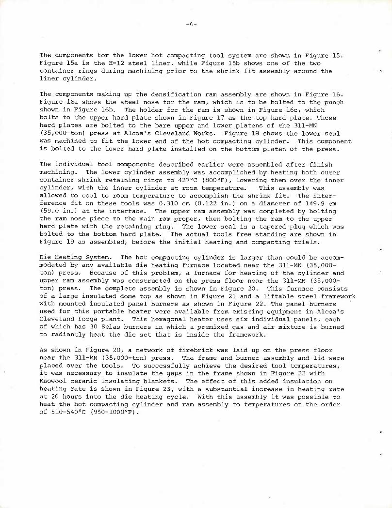
The components for the lower hot compacting tool system are shown in Figure 15. Figure 15a is the H-12 steel liner, while Figure 15b shows one of the two container rings during machining prior to the shrink fit assembly around the liner cylinder.
The components making up the densification ram assembly are shown in Figure 16. Figure 16a shows the steel nose for the ram, which is to be bolted to the punch shown in Figure 16b. The holder for the ram is shown in Figure 16c, which bolts to the upper hard plate shown in Figure 17 as the top hard plate. These hard plates are bolted to the bare upper and lower platens of the 311-MN (35,000-ton) press at Alcoa's Cleveland Works. Figure 18 shows the lower seal was machined to fit the lower end of the hot compacting cylinder. This component is bolted to the lower hard plate installed on the bottom platen of the press.
The individual tool components described earlier were assembled after finish machining. The lower cylinder assembly was accomplished by heating both outer container shrink retaining rings to 4270C {800oF), lowering them over the inner cylinder, with the inner cylinder at room temperature. This assembly was allowed to cool to room temperature to accomplish the shrink fit. The inter- ference fit on these tools was 0.310 cm (0.122 in.) on a diameter of 149.9 cm (59.0 in.) at the interface. The upper ram assembly was completed by bolting the ram nose piece to the main ram proper, then bolting the ram to the upper hard plate with the retaining ring. The lower seal is a tapered plug which was bolted to the bottom hard plate. The actual tools free standing are shown in Figure 19 as assembled, before the initial heating and compacting trials.
Die Heating System. The hot compacting cylinder is larger than could be accom- modated by any available die heating furnace located near the 311-MN (35,000- ton) press. Because of this problem, a furnace for heating of the cylinder and upper ram assembly was constructed on the press floor near the 311-MN (35,000- ton) press. The complete assembly is shown in Figure 20. This furnace consists of a large insulated dome top as shown in Figure 21 and a liftable steel framework with mounted insulated panel burners as shown in Figure 22. The panel burners used for this portable heater were available from existing equipment in Alcoa's Cleveland forge plant. This hexagonal heater uses six individual panels, each of which has 30 Selas burners in which a premixed gas and air mixture is burned to radiantly heat the die set that is inside the framework.
As shown in Figure 20, a network of firebrick was laid up on the press floor near the 311-MN (35,000-ton) press. The frame and burner assembly and lid were placed over the tools. To successfully achieve the desired tool temperatures, it was necessary to insulate the gaps in the frame shown in Figure 22 with Kaowool ceramic insulating blankets. The effect of this added insulation on heating rate is shown in Figure 23, with a substantial increase in heating rate at 20 hours into the die heating cycle. With this assembly it was possible to heat the hot compacting cylinder and ram assembly to temperatures on the order of 510-540oC (950-1000oF).
-7-
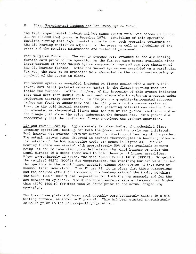
B. First Experimental Preheat and Hot Press System Trial
The first experimental preheat and hot press system trial was scheduled in the 311-MN (35,000-ton) press in December 1974. Scheduling of this operation required fitting this experimental activity into such operating equipment as the die heating facilities adjacent to the press as well as scheduling of the press and the required maintenance and technical personnel.
Vacuum System Checkout. The vacuum systems were attached to the die heating furnace cars prior to the operation as the furnace cars became available since incorporation of these vacuum system components required complete shutdown of the die heating furnace. After the vacuum system was assembled on a particular furnace, the cans to be preheated were assembled to the vacuum system prior to checkout of the system in place.
The vacuum system as assembled included on flange sealed with a soft multi- layer, soft steel jacketed asbestos gasket in the flanged opening that was inside the furnace. Initial checkout of the integrity of this system indicated that this soft iron gasket would not seal adequately to maintain a vacuum under production assembly conditions. In its place a graphite-impregnated asbestos gasket was found to adequately seal the hot joints in the vacuum system at least in the cold initial checkout. This gasketing material was used both at the elevated metal-to-metal flange near the top of the preheat container and at the flange just above the valve underneath the furnace car. This gasket did successfully seal the in-furnace flange thoughout the preheat operation.
Die and Powder Heat-Up. Approximately two days before the scheduled first pressing operation, heat-up for both the powder and the tools was initiated. Tool heat-up was started somewhat before the start-up of heating of the powder. The actual heat-up rates observed in several thermocouples in handling holes on the outside of the hot compacting tools are shown in Figure 23. The die heating furnace was started with approximately 50% of the available burners being lit and no insulation provided between the panel burners or under the panel burners in a steel frame used to hold these panel burner assemblies. After approximately 12 hours, the dies stabilized at 1480C (300oF). To get to the required 4820C (900oF) die temperatures, the remaining burners were lit and the openings in the panel burner assembly closed with 7.6-cm (3-in.) mats of Kaowool fiber insulation. From Figure 23, it is clear that these corrections had the desired effect of increasing the heat-up rate of the tools, reaching 480-538oC (900o-1000oF) die temperature for both the ram assembly and for the hot compacting cylinder. The die's outer surfaces were at temperatures higher than 480oC (900oF) for more than 24 hours prior to the actual compacting operation.
The lower base plate and lower seal assembly were separately heated in a die heating furnace, as shown in Figure 24. This had been started approximately 30 hours prior to the hot compacting operation.
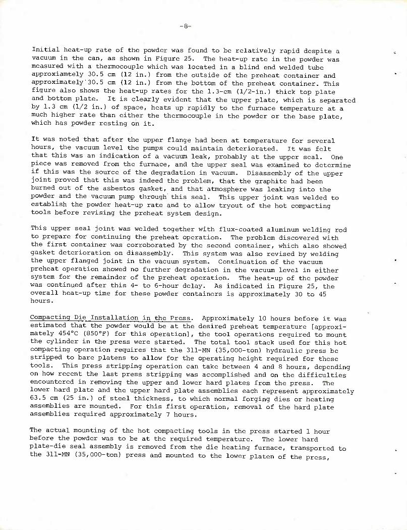
Initial heat-up rate of the powder was found to be relatively rapid despite a vacuum in the can, as shown in Figure 25. The heat-up rate in the powder was measured with a thermocouple which was located in a blind end welded tube approxiamtely 30.5 cm (12 in.) from the outside of the preheat container and approximately 30.5 cm (12 in.) from the bottom of the preheat container. This figure also shows the heat-up rates for the 1.3-cm (1/2-in.) thick top plate and bottom plate. It is clearly evident that the upper plate, which is separated by 1.3 cm (1/2 in.) of space, heats up rapidly to the furnace temperature at a much higher rate than either the thermocouple in the powder or the base plate, which has powder resting on it.
It was noted that after the upper flange had been at temperature for several hours, the vacuum level the pumps could maintain deteriorated. It was felt that this was an indication of a vacuum leak, probably at the upper seal. One piece was removed from the furnace, and the upper seal was examined to determine if this was the source of the degradation in vacuum. Disassembly of the upper joint proved that this was indeed the problem, that the graphite had been burned out of the asbestos gasket, and that atmosphere was leaking into the powder and the vacuum pump through this seal. This upper joint was welded to establish the powder heat-up rate and to allow tryout of the hot compacting tools before revising the preheat system design.
This upper seal joint was welded together with flux-coated aluminum welding rod to prepare for continuing the preheat operation. The problem discovered with the first container was corroborated by the second container, which also showed gasket deterioration on disassembly. This system was also revised by welding the upper flanged joint in the vacuum system. Continuation of the vacuum preheat operation showed no further degradation in the vacuum level in either system for the remainder of the preheat operation. The heat-up of the powder was continued after this 4- to 6-hour delay. As indicated in Figure 25, the overall heat-up time for these powder containers is approximately 30 to 45 hours.
Compacting Die Installation in the Press. Approximately 10 hours before it was estimated that the powder would be at the desired preheat temperature [approxi- mately 4540C (850oF) for this operation], the tool operations required to mount the cylinder in the press were started. The total tool stack used for this hot compacting operation requires that the 311-MN (35,000-ton) hydraulic press be stripped to bare platens to allow for the operating height required for these tools. This press stripping operation can take between 4 and 8 hours, depending on how recent the last press stripping was accomplished and on the difficulties encountered in removing the upper and lower hard plates from the press. The lower hard plate and the upper hard plate assemblies each represent approximately 63.5 cm (25 in.) of steel thickness, to which normal forging dies or heating assemblies are mounted. For this first operation, removal of the hard plate assemblies required approximately 7 hours.
The actual mounting of the hot compacting tools in the press started 1 hour before the powder was to be at the required temperature. The lower hard plate-die seal assembly is removed from the die heating furnace, transported to the 311-MN (35,000-ton) press and mounted to the lower platen of the press.
-9-
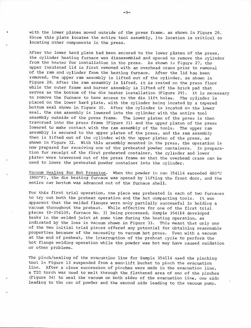
with the lower platen moved outside of the press frame, as shown in Figure 26. Since this plate locates the entire tool assembly, its location is critical to locating other components in the press.
After the lower hard plate had been secured to the lower platen of the press, the cylinder heating furnace was disassembled and opened to remove the cylinder from the heater for installation in the press. As shown in Figure 27, the upper insulated lid is first removed with an overhead crane prior to removal of the ram and cylinder from the heating furnace. After the lid has been removed, the upper ram assembly is lifted out of the cylinder, as shown in Figure 28. After the ram assembly is lifted, it is rested on the press floor while the outer frame and burner assembly is lifted off the brick pad that serves as the bottom of the die heater installation (Figure 29). It is necessary to remove the furnace to have access to the die lift holes. The cylinder is placed on the lower hard plate, with the cylinder being located by a tapered bottom seal shown in Figure 30. After the cylinder is located on the lower seal, the ram assembly is lowered into the cylinder with the entire tool assembly outside of the press frame. The lower platen of the press is then traversed into the press frame (Figure 31) and the upper platen of the press lowered to make contact with the ram assembly of the tools. The upper ram assembly is secured to the upper platen of the press, and the ram assembly then is lifted out of the cylinder with the upper platen of the press, as shown in Figure 32. With this assembly mounted in the press, the operation is now prepared for receiving one of the preheated powder containers. In prepara- tion for receipt of the first preheated container, the cylinder and lower platen were traversed out of the press frame so that the overhead crane can be used to lower the preheated powder container into the cylinder.
Vacuum Sealing for Hot Pressing. When the powder in can 354114 exceeded 460oC (860oF), the die heating furnace was opened by lifting the front door, and the entire car bottom was advanced out of the furnace shell.
For this first trial operation, one piece was preheated in each of two furnaces to try out both the preheat operation and the hot compacting tools. It was apparent that the welded flanges were only partially successful in holding a vacuum throughout the preheat. While effective for one of the first trial pieces (S-354109, furnace No. 3) being processed. Sample 354114 developed leaks in the welded joint at some time during the heating operation, as indicated by the loss in vacuum shown in Figure 33. This meant that only one of the two initial trial pieces offered any potential for obtaining reasonable properties because of the necessity to vacuum hot press. Even with a vacuum at the end of preheat, the interruption of the preheat cycle to perform the hot flange welding operation while the powder was hot may have caused oxidation or other problems.
The pinch/sealing of the evacuation line for Sample 354114 used the pinching tool in Figure 13 suspended from a man-lift bucket to pinch the evacuation line. After a close succession of pinches were made in the evacuation line, a TIG torch was used to melt through the flattened area of one of the pinches (Figure 34) to seal the vacuum on both sides of the evacuation line, one side leading to the can of powder and the second side leading to the vacuum pump.
-10-
P/M Billet Hot Pressing. After the line was severed with the TIG torch, a fork lift truck was used to lift the can from the car bottom furnace and transport the can to the side of the 311-MN (35,000-ton) press where the cylinder awaited its first preheated container. An overhead crane was used to lift the preheated can from the fork lift and lower the can into the cylinder, as shown in Figure 35. Because of wrinkling of the can adjacent to the weldment up the side of the can, difficulty was experienced in getting the can completely into the cylinder. In order to try out the tools, the can was forced into the cylinder with the upper platen and with the ram assembly.
With the can in the cylinder under the ram, the first piece was ready for hot pressing. A 78.7-cm (31-in.) diameter x 10.1-cm {4-in.) long slice of 7050 alloy ingot was added on top of the powder container to assure complete filling of the tapered portion of the cylinder with metal at 100% density. Initially, six of the eight hydraulic cylinders of the press were used to pressurize the ram for initiating the hot pressing operation. While displacement was being carefully monitored during the pressing operation, the upper ram appeared to cease motion with six cylinders operating. This momentary pause in the ram's travel was very brief and was followed by relatively rapid but short acceleration of the ram as metal apparently was pushed between the lower seal and the cylinder, lifting the cylinder as shown in Figures 36 and 37. It is apparent from these observations that the required level of friction to hold the cylinder down on the lower seal was not generated by the tool geometry as it was fabricated.
Detailed stress analyses indicated that the cylinder should have expanded approximately 0.38 cm (0.150 in.) on the diameter at the lower seal diameter area. To accommodate this increase in diameter, it was necessary for the cylinder to move an equal amount [i.e., 0.38 cm (0.150 in.)] down the 45- degree sealing taper between the cylinder and the lower seal. It was found on additional measurements after this piece was pressed and the compact removed from the cylinder that the clearance between the cylinder and the lower hard
plate was 0.076 cm (0.030 in.).
During the hot pressing operation, as pressure was generated in the cylinder, the cylinder would expand and friction would drive the cylinder down the 45- degree sealing taper. After the cylinder was driven down 0.076 cm (0.030 in.), the cylinder apparently bottomed out on the hard plate. Application of additional pressure resulted in continued expansion of the cylinder lower diameter, opening the gap between the lower seal and the cylinder, allowing metal to extrude into this gap and generate cylinder lifting force. As seen in Figure 36, the net amount of cylinder lift and resultant flash thickness reached at least 2.5 cm (1 in.) on one side.
Modifications for Further Process Development. This first preheat and tooling trial resulted in several preheat and tool modifications that would be required to successfully complete the scaled-up powder compacting feasibility demonstra- tion. It was apparent that the preheat container design required modification in three areas: (1) the evacuation system would have to be completely welded construction and continuous to the valve on the underside of the car bottom furnace; (2) the can wall thickness should be increased to minimize buckling
-11-
of the can under atmospheric pressure and at relatively high temperatures; (3) the can diameter should be decreased slightly to accommodate any small variations in the can diameter as a result of the heating operation. In addition to the can modifications, it appeared desirable to make several tool modifications. The first and most important was to increase the cylinder-to-base plate clearance to allow for proper expansion of the tools and movement of the tools down the lower seal as the cylinder diameter increased under pressure. Secondly, it appeared evident that some provision for more positive sealing of both the lower seal and the upper seal around the sliding ram nose would be necessary to minimize hang-up potential of these tools.
The hot compacting tools were modified by machining the bottom of the hot compacting cylinder to remove approximately 0.38 cm (.150 in.) from the bottom surface, i.e., the surface of the cylinder that faces the bottom hard plate. Measurements at room temperature after the machining operation indicated that the cylinder-to-lower base plate clearance averaged 0.46 cm (.180 in.) all around the cylinder.
Replacement preheat containers were fabricated to 78.7 cm (31 in.) OD with 0.95-cm (3/8-in.) thick wall alloy aluminum plate. Powder for these new containers was basically the powder that was generated but not preheated in the December 1974 trials. This powder was transferred to the new preheat containers and vibratory loaded as previously for the initial loading operation, as shown in Figure 8. The smaller inside capacity of the new preheat containers is reflected in somewhat less powder weight per can (Table 7) compared to the earlier containers (Table 5). This necessitated generation of additional 78.7-cm (31-in.) diameter ingot slices to allow complete filling of the tapered portion of the hot compacting cylinder.
In addition to the six powders remaining from the first preheat run, one addi- tional MA87 alloy powder was generated for a one-piece preheat and tooling tryout. Powder size and composition of this melt (354687) are shown in Tables 3 and 4.
Extrusion of aluminum around the lower seal and some evidence of a small amount of aluminum extruding around the ram nose indicated the desirability of additional cylinder sealing. The use of sealing rings for both top and bottom seals of the hot compacting cylinder was suggested from Alcoa's experience with metal flow control in large extrusion cylinders. These seals are carbon steel rings machined to a triangular configuration, with their OD equal to the cylinder diameter at either the upper or lower seal, depending on which location the seal was intended for. The geometry in which these seals were to be used is shown in Figure 38. These rings were fabricated from a rolled and welded ring of carbon steel of the required outside diameter, to be machinable to the cylinder inside diameter at either the lower seal or the upper seal. After the triangular rings were machined, each ring was split to allow for expansion in diameter under pressure to prevent aluminum from extruding during the hot compacting operation.
With these materials fabricated and tool modifications completed, additional hot compacting runs in Alcoa's 311-MN (35,000-ton) press were scheduled for May 10-15, 1975.
-12-
C. Second Experimental Preheat and Billet Hot Pressing - May 1975
Powder and Die Preheating. In the initial preheat trial, an excessively long time was required to heat the powder to temperature when the vacuum is maintained during the heat-up. Approximately 60 hours' heating time would be required to get the powder to the desired preheat temperature of 482-510oC {900-950oF). It is known that powder will heat at a substantially higher rate when gas is present in the interstices between the powder particles. For this trial, we allowed the powder to generate its own atmosphere, which for these materials is a hydrogen atmosphere that results from the decomposition of hydrates on the aluminum particle surfaces. The powder preheat container was assembled to the vacuum system as previously, with the changed assembly using a single piece all-welded vacuum line required to avoid flanged connections in the hot zone of the furnace. This vacuum line was bolted to an under-car vacuum line outside the hot zone of the furnace.
The heating of the hot compacting cylinder was initiated approximately two days before scheduled hot compacting was to take place, with tool heating performed as previously. Powder preheat rates observed in the first heating and tool trial in December 1974 indicated that approximately 30 to 36 hours would be required to heat powder when an atmosphere exists among the powder particles, as was the case for one of the pieces heated for the December 1974 trial. For this operation, provisions were made to purge the vacuum system with nitrogen by back filling after initially evacuating the system with the can and the vacuum system at room temperature. After back filling with nitrogen, an open valve in the evacuation system provided an exit for expanding gas from the preheat container. The initial evacuation of the system prior to back filling indicated that no vacuum leaks existed in the assembled system.
Approximately 12 hours after the cylinder heating was initiated, the first trial preheat container was advanced into the preheat furnace to initiate the preheating operation. The heat-up rate observed for this piece (S-354687) is shown in Figure 39 for a thermocouple located 30.5 cm (12 in.) from the outside and 30.5 cm (12 in.) from the bottom of the container. The furnace set temperature initially was 5240C (9750F), with the furnace monitoring thermocouple at the rear of the furnace near the top.
First Billet Pressing Operation. Approximately 8 hours before the hot pressing was to begin, the press stripping procedure described earlier was initiated in preparation for installing the compacting tools in the press.
After 40 hours' heating, evacuation of the preheated container was initiated with a mechanical pump. After 50 minutes, vacuum was at 6.67 kPa (50 ym Hg). After 53 minutes' rough pumping, pumping with jet-booster pump was initiated, with thermocouple vacuum gauge going below 133 Pa (1 ym Hg) reading within minutes. Temperatures of container at this point, 41.3 hours after start of heat-up and 1.3 hours after start of pumpdown, were 5160C (960oF) in the top surface of the can 485°C (905oF) in the bottom of the can, and 4990C (930°F) in the powder.
-13-
Die temperatures at installation were as follows: bottom hard plate - 3990C (750oF); cylinder at 501-507°C (933-9450F); top hard plate at 474- 4880C (885-910oF). Die installation excluding stripping the press required 66 minutes from lifting the bottom hard plate off the die heating furnace to completion of bolt-up of the top hard plate assembly to the upper platen of the press. Cylinder-to-base plate clearance was measured at 0.38 cm (0.150 in.) all around.
Temperatures of preheated container and powder immediately before starting the evacuation line sealing were: top - 5160C (9600F) ,- bottom - 4870C (908oF); powder - 502oC (9350F). Vacuum reading was below 133 Pa (1 ym Hg) .
Seal procedure consisted of several operations, including the following: (1) pinching the evacuation line as close to the can as possible O10 cm ('M in.) from the can surface], then four pinches over 3.8 cm (1-1/2 in.) of pipe length, then one pinch above this area; and (2) weld-melt sealing through the center of the 3.8-cm (1-1/2-in.) long flattened area with a DC arc welder and flux-coated aluminum welding rod to simultaneously seal the vacuum line and separate the can from the vacuum system. The pinching operation for a later container is shown in Figure 40. For this trial container, one welding rod sealed 5.7 cm (2-1/4 in.) of the pinch, and a second rod was required to seal the remaining 1.9 cm (3/4 in.) of the flattened area. No changes in the vacuum readings were noted during the weld separation procedure, indicating vacuum retention throughout this procedure on both sides of the vacuum seal.
After line sealing, the can was transported to the 311-MN (35,000-ton) press and lifted into the cylinder, as shown in Figure 35. At this point, the bottom split sealing ring was in place in the bottom of the cylinder. The cylinder-base assembly was transported into the press under the ram as in Figure 32 and the pressing of the billet initiated.
The ram was pressed 15 cm (6 in.) into the cylinder to allow adding a short 10 cm (4-in.) thick slice of ingot required to fill the tapered portion of the cylinder. On top of the ingot slice, the split steel ring with a downward and inward facing 45-degree taper was added to further restrict aluminum from extruding into the ram nose-to-cylinder clearance that opens up under compacting pressure.
Initially, six of eight cylinders were used for pressing to assure retention of metal in the cylinder, applying 233.5-MN (26,250-tons') load plus approximately 17.8 MN (2000 tons') upper platen weight. This is equivalent to approximately 469.5 MPa (68,100 psi) ram face pressure. The ram advanced into the cylinder to leave 11.4 cm (4-1/2 in.) of cylinder top-to-ram holder clearance, indicating full density based on metal volume in tools. After two minutes' dwell at pressure, during which no ram advance occurred, the press was switched to eight cylinders to allow pressing at 620.5 MPa (90,000 psi) as desired. Added pressure initially showed no further ram advance but then a sudden 0.6-cm (1/4-in.) advance, when full line pressure was reached. No pressure dwell was used with eight cylinders beyond a slow rate of application of
pressure.
•14-
For billet ejection, the press was switched to two cylinders and the ejection ring installed under the cylinder (Figure 41), with the cylinder suspended from the upper hard plate with a set of matched chains. On application of two cylinders' pressure (full pressure was not reached) equivalent to up to 97.9 MN (11,000 tons) or 178.6 MPa (25,900 psi), ejection was accomplished with a rather sudden movement and pressure release, with the ram bottoming out on the cylinder. The billet did not fall free from the cylinder, however, but required more than the pushing stroke of 10.2 cm (4 inches). This was accomplished after the following tool hang-up was corrected.
On withdrawal from the cylinder, the ram went up 15 cm (6 in.) and then stuck, with the ram lifting the cylinder. Bumping the cylinder with a manipulator moved the cylinder down 5-7 cm (2-3 in.) further; but separating the cylinder from the ram required holding the cylinder down to the base plate with heavy chains and pulling the ram away from the cylinder.
Flash was evident all around the ram as the cause of cylinder hang-up on the ram. It is apparent that use of a separate, loose ram nose and increased ram- to-cylinder clearance would be desirable to completely eliminate cylinder hang-up on the ram with flash. The tapered steel sealing ring did not eliminate flash around the ram nose but did effectively seal the cylinder at the bottom and prevent metal extrusion past the bottom seal.
Finished billet (S-354687, MA87 alloy) was 81.76 cm (32-3/16 in.) top diameter, tapering to approximately 85.1 cm (33.5 in.) bottom diameter x 102.08 cm (40- 3/16 in.) long.
Further Billet Generation. Six additional cans of powder, three each of MA67 and MA87 alloys, were connected to the vacuum systems, as shown in Figure 42— three cans per furnace car. These containers were arranged on the cars as shown in Figure 43.
Prior to heat-up, each system was vacuum pumped to verify system continuity and integrity, with No. 3 die heater cans (three) pumping down to 6.0 kPa (45 ym Hg) with booster pump operating [to 33.3 kPa (250 ym Hg) quickly with mechanical pump] after retightening some vacuum line bolts. Both systems were back-filled with nitrogen to assure low oxygen, low moisture atmosphere in the cans prior to their generating their own H atmosphere during preheating.
Heat-up rates observed in these furnaces are shown in Figures 44 and 45. Furnace No. 3 was substantially slower than Furnace No. 4 due to a number of malfunctioning burners in this direct gas-fired furnace, further confounded by a brief furnace shutdown during heating. As evident in the heat-up rates observed in each furnace, the heating rate in the lower front area of the furnace was substantially slower than in the center or rear portion of the furnace. This was contrary to the temperature pattern indicated by earlier temperature surveys. This appears to be related to closing of an exit vent from the original design for energy conservation. As a result, the front powder containers were judged to be too cold for adequate degassing at the time hot pressing was initiated.
-15-
Because of the faster heat-up rate achieved in Furnace No. 4, evacuation was started on the three cans in that furnace after 33 hours and 40 minutes' preheat time, while evacuation of cans on Furnace No. 3 was started after 44- 1/2 hours. Evacuation of containers in Furnace No. 3 proceeded without incident in 40 minutes, but the three containers in Furnace No. 4 would not pump to less than 133.3 kPa (1000 ym Hg) vacuum level. Then valves to each can were cycled, and the center can (S-354108, alloy MA87) was found to be leaking. Inspection revealed a crack in the side of the can caused by melting from burner flame impinging on the side of the can. Further evacuation of the remaining two sound containers proceeded without incident.
Tool installation proceeded as previously outlined, with complete installation requiring 51 minutes (compared to 66 minutes for the last setup). The intended order of sealing was planned as follows: 354113 (No. 4, rear); 354110 (No. 3, rear); and 354112 (No. 3, center). Further heating or moving of 354111 and 354107 containers would allow subsequent hot pressing when they were heated sufficiently.
Vacuum sealing of 354113 container (MA67) was accomplished as described earlier, and hot pressing was initiated as the earlier sample. Delay in completing pressing was caused by initially pressing too far into the cylinder before adding the ingot slice and sealing ring. The ram was momentarily stuck to the cylinder with flash but was freed with much less difficulty than previously. Pressing was completed with additon of ingot and sealing ring in cylinder and pressing with six cylinders [469 MPa (68 ksi) ram face pressure]. Since the ram advanced to leave only 10.8 cm (4-1/4 in.) cylinder-to-ram holder clearance with six cylinders pressing, further application of pressure was deleted from the procedure.
This billet was ejected with the same procedure used previously but was cleanly free from the cylinder with 0.64 to 1.3 cm (1/4 to 1/2 in.) of ram travel remaining. This showed that the cylinder expansion from 469 MPa (68 ksi) pressure requires 9.5-cm (3-3/4-in.) billet downward displacement to go beyond the cylinder's elastic grip on the billet, while cylinder expansion from 620.5 MPa (90 ksi) pressure requires 12.7 cm (5 in.) or more downward displacement to be clear of the cylinder.
The cylinder was again hung up on the ram with aluminum flash, requiring that the ram be pulled away from the cylinder with heavy chains and cables, not without some chain link stretching before the cylinder pulled free and fell to the base plate. Flash around the ram nose was removed before the next billet was prepared for pressing.
Vacuum sealing of container 354110 (MA87 alloy) was accomplished as described previously and the container loaded into the cylinder. After correcting an alignment problem of the cylinder base plate to ram, the billet was pressed with ingot slice and steel sealing ring in place. After one minute' pressure dwell with six cylinders, eight-cylinder [311-MN (35,000-ton) hydraulic load + dead weight] pressing for 5 seconds was used with almost no evidence of further ram movement.
■16-
The ejection procedure was applied as previously, but the billet was not free of the cylinder and, in addition, the cylinder was stuck on the ram as previously. Attempts to pull the ram out of the cylinder succeeded only in breaking some large 2,5-cm (1-in.) diameter link chains and 7.6-cm (3-in.) diameter steel lift pins. For personnel safety and press integrity, no further attempts to pull the tools apart were made, and further billet preheating and pressing were dropped to allow fabrication and evaluation of products from available billets with remaining contract funds. The billet dropped from the cylinder as the cylinder cooled approximately one day after pressing, but the ram assembly had to be partially disassembled to allow the ram nose to be pushed out of the container.
D. Fabrication of Mill Products
From the billet pressing operations, three billets resulted—two MA87 and one MA67. Mill products to be fabricated from these billets after scalping were as follows:
MA87 - 354687 - Forge to slab; roll to 5-cm (2-in.) plate.
- 354110 - Forge to 63.5 cm (25 in.) diameter; extrude Section 263902.
- Generate a cylinder-type die forging.
MA67 - 354113 - Forge to 63.5 cm (25 in.) diameter; extrude Section 263902.
- Generate a cylinder-type die forging.
The billets were scalped to 76.2 cm (30 in.) diameter and etched to show the remainder of the encapsulating can. As shown in Figure 46, all but 354113 cleaned up completely in the initial scalp. For initial forging, the can ends were left on the compact to aid in the detection of end defects.
Plate. To fit Alcoa's Davenport (Iowa) Works plate mill, a minimum 76-cm (30-in.) width was necessary to guide a slab through the 406-cm (160-in.) mill. Further, it was desired to use hot rolling for as much of the fabrication as possible, so a forged slab thickness of 30.5 cm (12 in.) was chosen, thus leaving the slab length at 160 cm (63 in.), somewhat shorter than optimum for feeding the 406-cm (160-in.) mill.
The hot pressed compact was reheated to 3710C (700oF) and draw-forged, as illustrated in Figure 47, to 30.5 cm (12 in.) thick x 76 to 77.5 cm (30 to 30-1/2 in.) x 160 cm (63 in.) long, with the cylinder-filling ingot slice delaminating early in forging.
This slab (shown in Figure 48) was shipped to Alcoa's Davenport Works where it was scalped to 27.46 cm (10-13/16 in.) thick and sawed to 151.3 cm (59- 1/16 in.) long to square the ends for uniform bite in the mill. The slab was reheated to 3990C (750oF) for 16 hours and hot rolled with the rolling schedule shown in Table 8, with metal starting temperature of 3710C (700oF) and finish temperature of 304-316oC (580-600oF).
-17-
The plate was rough sawed to 73.98 cm (29-1/8 in.) wide x 706 cm (278 in.) long and heat treated at Davenport Works as described in the following section on properties.
Extrusions. Two compacts for generating extrusions and die forgings were scalped and were reheated to 356-3880C {690-730oF) and draw-forged to 64-cm (25-in.) diameter x 117-122 cm (46-48 in.) long. Both pieces had a 7.6 to 8.9-cm (3 to 3-1/2-in.) deep center pipe at the billet end that had been the bottom of the compact. A section of the forged compact from the bottom end [73.7-cm (29-in.) length of 354110 and 77.5-cm (30.5-in.) length of 354113] was cut from the 64-cm (25-in.) diameter forging for extrusion stock for Alcoa's Lafayette (Indiana) Works. Section 263902, shown in Figure 49 (12.08 extrusion ratio), was selected for evaluation because of its testability and because it has been fabricated and tested extensively in other alloys, including 7050.
The billets for extruding were scalped to 62.8 cm (24-3/4 in.) diameter, sawed to lengths of 63.8 cm (25-1/8 in.) (354110) or 60.3 cm (23-3/4 in.) (354113), induction reheated to 4270C (800oF) , and extruded from a 64.1-cm (25-1/4-in.) diameter cylinder operated at 3990C (750oF) in the 124.4 MN (14,000-ton) press at Alcoa's Lafayette Works. MA87 was extruded at 13.7 cm (5.4 in.) per minute product speed, breaking out at 214 MPa (31.1 ksi) and running at 175.8 MPa (25.5 ksi). Some corner checking was observed in the first six feet of product, suggesting that somewhat lower extrusion temperature or slower product speed would be desirable. Approximately 4.9 M (16 ft) of product length were generated in MA87.
MA67 was reheated to 410oC (770°F) for extrusion, breaking out at 188 MPa (27.3 ksi) and running at 167 MPa (24.2 ksi) at product speed of 8.4 cm (3.3 in.) per minute. No checking was observed on the MA67 extrusion over its 5-M (16-1/2-ft) length.
The extrusions were heat treated and aged at Alcoa's Lafayette Works as described in the following section on properties.
Die Forgings. Initially, a die forging normally fabricated from hand-forged stock was to be generated from the 63.5-cm (15-in.) diameter forged billet sections. Further draw forging to 38.1 cm (15 in.) diameter at 371°C (700oF) resulted in extensive cracking of the billets, severely limiting the amount of sound metal remaining for further preform forging. When further forging of the sound portion of the 38.1-cm (15-in.) diameter billets resulted in further cracking, an alternate forging was selected for evaluation—die 12767 (Figure 50). This cylinder forging is normally generated from extruded 11.4-cm (4-1/2-in.) diameter stock.
Accordingly, 27.9-cm (11-in.) diameter billets were machined from the P/M forged cylinders, generating two MA87 billets and one MA67 billet. These were induction reheated to 427°C (800oF) and extruded at ATC to 11.4-cm (4- 1/2-in.) diameter rod at 30.5 cm (1 ft) per minute product speed to generate stock for making two MA87 and one MA67 forgings.
-18-
The forgings were generated with two press operations in a 71,1-MN (8000-ton) press at Alcoa's Cleveland Works, reheating stock to 3820C (720oF) and forging in 360oC (680oF) dies, cold triinining forgings to remove flash, reheating to 404oC (760of), and forging to the finish configuration in dies at 3430C (650oF)
The forgings were heat treated to a T6 temper at Alcoa's Cleveland Works as described in the properties section that follows.
II. PROPERTIES OF PRODUCTION-FABRICATED P/M MILL PRODUCTS
A. Plate
Alloy MA87 5-cm (2-in.) thick plate was heat treated at Alcoa's Davenport Works for 2.4 hours at 471-4930C (880-920oF), cold water quenched, stretched 2.6%, naturally aged five days, and artificially aged 24 hours at 1180C (2450F). The plate was ultrasonically inspected and a number of sonic indications marked to define property sampling locations. The plate was second-step aged at Alcoa Technical Center, with individual pieces being aged 1, 4, 14, and 24 hours at 1630C (3250F). These pieces of plate were sampled for longitudinal, long transverse, and short transverse tensile specimens, compact tension fracture toughness specimens, longitudinal axial-stress smooth and notched (K = 3) fatigue specimens, short transverse 0.3-cm (1/8-in.) diameter tensile specimens for stress corrosion tests, and panels for the EXCO predictive exfoliation corrosion tests with surfaces machined to expose mid-thickness and thickness/10 planes in the plate.
Results and Discussion: Plate. Results of tensile and fracture toughness tests are summarized in Table 9; accelerated stress corrosion and exfoliation corrosion tests are in Table 10; and fatigue test results are shown in Tables 11 and 12. These properties are discussed below.
The strength/fracture toughness relationships for MA87 plate are shown graphically in Figure 51 for all three test directions. Several significant points to note are:
1. Very high fracture toughness in all test directions was demon- strated, with MA87 having higher toughness than 7050-T73651 plate at equal strength or equal toughness with 6-8 ksi higher yield strength in longitudinal and short transverse directions.
2. Unusually high, long transverse strength was observed, which may be related to the "draw" forging procedure used to generate the rolling slab (see Figure 47). Plate grain texture may explain this strength difference.
3. Compared to lab-fabricated 3.8-cm (1.5-in.) thick MA87 plate, this production-fabricated plate has nearly identical strength and short transverse fracture toughness but somewhat lower longitudinal fracture toughness. Since these longitudinal toughness values are invalid K 's, it is possible that this longitudinal toughness difference Ic
for valid tests may be less than shown here.
-19-
4. Compared to 7475 plate, MA87 appears to be comparable in toughness, although MA87's high long transverse strength in this plate suggests a superior strength/toughness relationship for MA87.
The strength/stress corrosion cracking resistance relationships for the various tempers of MA87 plate are shown in Figure 52. Significant observations from this information include:
1. Aging for 14 hours at 1630C (3250F) is necessary to reach near immunity to SCC, as indicated by passing 84 days without failure at 310 MPa (45 ksi) stress. In this temper, MA87 with 448 MPa (65 ksi) short transverse yield strength is equal in strength to 7075-T651 but with substantially better SCC resistance.
2. Short time second-step aging [4 hours at 1630C (3250F)] generates an intermediate level of SCC resistance, approximately equivalent to that of 7075-T7651 but at a short transverse yield strength of 476 MPa (69 ksi). This compares to 427 MPa (62 ksi) yield strength for 7075-T7651 or 7050-T73651.
3. Compared to 7050-T73651 plate, MA87 offers equal SCC resistance with up to 13% stronger than 7050-T73651, 41-55 MPa (6-8 ksi) higher short transverse yield strength.
Fatigue performance of MA87 plate is summarized in Tables 12 and 13 and shown graphically in Figures 53 and 54 for notched and smooth specimens, respectively. Notable observations in these data include the following:
1. For the stronger MA87 tempers (e.g., Sample 355471), notched fatigue strength indicates a 131-138 MPa (19-20 ksi) endurance limit (>10' cycles to failure), which is substantially superior to 7050-T73651 and 7075-T7351 plate, with endurance limits on the order of 83-90 MPa (12-13 ksi).
2. Notched fatigue appears to be influenced by strength, as indicated by somewhat lower endurance limits projected for the lower strength tempers of MA87 plate, although these are better than 7050 and 7075.
3. Smooth specimen fatigue performance shows considerable scatter, but results show P/M MA87 plate generally above 7050-T7 3651 and at the top of the scatter band of 7075-T7351. Smooth specimen endurance limits appear to be in the range of 241-262 MPa (35-38 ksi).
Exfoliation corrosion testing has been limited to the predictive MASTMAASIS and EXCO tests, with the results shown in Table 11 and Figure 55. Differences in exfoliation ratings in these two tests suggest that the EXCO rating is confused by structure-corrodant interactions that are an artifact of this test. While further study of predictive tests for P/M products is underway, it is felt that the following observations based on the MASTMAASIS are most accurate until atmospheric tests are completed:
1. While slight exfoliation occurred with slightly increased overaging, SCC resistance improved markedly as a result of the same slight
-20-
overaging. In ingot 7XXX series alloys, exfoliation resistance is improved by slight overaging, but extensive overaging is required to raise SCC resistance.
2. With the MASTMAASIS test showing no worse than E(A) ratings for any temper, MA87 plate can be expected to show no exfoliation in service.
MA87 achieves good general corrosion resistance at near its peak strength of 74 ksi longitudinal yield strength. Testing in other accelerated and natural atmospheres will be used to establish the true corrosion ratings of this plate and establish correlation between these predictive ratings shown here and true atmospheric exposure.
B. Extrusions
MA67 and MA87 extrusions in the section shown in Figure 49 were heat treated at Alcoa's Lafayette Works for 2 hours at 488-4930C (910-920oF), cold water spray quenched, naturally aged six days, and artificially aged 24 hours at 1210C (250oF). The extrusions were second-step aged as individual sections at 1630C (3250F) for the times shown in Tables 14 and 15. These sections were each sampled from the 4.6-cm (1.8-in.) thick center section for longitudinal, long transverse, and short transverse tensile properties, for 0.3-cm (1/8- in.) diameter short transverse tensile specimens for stress corrosion tests, and panels for the EXCO predictive exfoliation corrosion tests that expose mid-thickness and thickness/10 planes from the center section of the extrusion.
Results and Discussion: Extrusions. Tensile and fracture toughness properties of the P/M extrusions are summarized in Tables 14 and 15, stress corrosion cracking and exfoliation corrosion test results in Table 16, notched specimen fatigue results in Table 17, and smooth specimen fatigue results in Table 18. The results of these tests are discussed below.
Strength properties of the P/M extrusions shown in Tables 14 and 15 are substantially below strengths demonstrated earlier for 5-cm (2-in.) diameter extruded rod in these same alloys. For the same temper, these production-scale extrusions have longitudinal yield strengths from 27 to 90 MPa (4 to 13 ksi) lower than previous, lab-fabricated extrusions. These differences were greatest for the higher strength tempers, as illustrated in Figure 56, where the relationship between yield strength and electrical conductivity is shown for both alloys in lab and plant-fabricated extrusions. From this figure, significant observations include:
1. Production extrusions have much lower strength at equal conductivity or lower conductivity at equal strength compared to lab 5-cm (2- in.) diameter extrusions.
2. For an identical temper (points marked with the same number), conductivity is generally higher and strength lower for the plant P/M extrusion.
Since electrical conductivity in these materials is strongly dependent on the amount of soluble elements out of solution, and equal conductivity indicates approximately equal amounts of the strengthening elements out of solution.
■21-
lower strength for an equal conductivity indicates a less efficient distribution of these soluble elements in the plant P/M extrusions. This could occur under several possible circumstances:
1. Inadequate heat treatment time or too low a temperature to dissolve all of the soluble elements in the solution heat treatment.
2. Delay and slow cool from solution treatment heating operation to the water quenching operation.
3. Slow quench of the extrusions due to spray quench equipment malfunction.
4. Excessive quench sensitivity, beyond the previous estimates.
Alcoa has initiated programs to develop corrective action and generate strengths comparable to those achieved in small-scale extrusions. These include the following:
1. Establish the effect of the billet processing differences between lab-scale and plant-scale processes on strength and structure of products.
2. Establish solution heat treatment time required for complete solution of soluble elements in extrusions from 84-cm (33-in.) diameter P/M hot pressed billet.
3. Verify quench sensitivity rating of these materials with samples from P/M extrusions. Earlier work with extrusions suggested that 95% of maximum strength could be achieved in cold water quenching of 5-cm (2-in.) thick sections.
4. Determine effect of heat-up time to second-step age temperature on T7 temper properties.
5. Establish the effect of stretch on aging kinetics and maximum strength achieved in P/M extrusions.
Preliminary results of reheat treatment show the conductivity to be decreased over the plant heat treated extrusions, as summarized in Table 19. The 3% lower conductivity for the ATC reheat treated samples could be indicative of 48 to 76 MPa (7 to 11 ksi) higher strength in the T6 temper, as has previously been demonstrated for hand forgings as shown in Table 20. The reheat treated samples are being tested for mechanical properties to confirm achieving the full strength capability of these alloys as extrusions.
The low strength achieved in these extrusions biases the bulk of the property comparisons, reducing the overall property advantages these materials have demonstrated in the laboratory. The fracture toughness to yield strength relationships for these extrusions are shown in Figure 57, with the lab- fabricated extrusion properties included for comparison. As indicated earlier, not only is strength lower than lab extrusions, but fracture toughness is also lower in the longitudinal direction for both alloys and in the short transverse
-22-
direction for MA87. Even with apparently low strength, MA67 extrusions match the short transverse toughness-strength capability of 7050-T73651 but was somewhat lower than 7050 in the longitudinal direction.
MA87 extrusions developed lower toughness than MA67, which may be indicative of inadequate vacuum in the hot pressing operation, or very slow quench, which can reduce both strength and toughness. This latter effect was clearly shown in earlier work with two of the P/M alloys in Phase IVA, reported in Reference 7, shown here in Figure 58. While the toughness reduction with slower quench is exaggerated with these alloys, the general effect may partially account for the lower toughness in these extrusions, with a predictive quench rate of 21"C (380F) per second for a cold water immersion quench, compared to 890C (160oF) per second quench rate for the 5-cm (2-in) diameter lab-processed extrusions.
The low strength of these extrusions results in a reduced strength-SCC rating for these materials compared to the earlier, lab-fabricated extrusions, as shown in Figure 59. Notably, at 310 MPa (45 ksi) sustained stress for MA87, the yield strength (YS) at which SCC greatly diminishes is on the order of 503 MPa (73 ksi) compared to 462 MPa (67 ksi) for this plant-fabricated MA87 extrusion for 30-day exposure in the A.I. test.
After 84 days' exposure (Figure 60), the rating of these plant P/M extrusions is unchanged from 30-day exposure results, while the lab extrusions show some decline in SCC performance. At 310 MPa (45 ksi) stress, both plant and lab extrusions show good SCC resistance at 462 MPa (67 ksi). At 241 MPa (35 ksi) stress, the difference between extrusions is evident in a 48 MPa (7 ksi) difference in strength, with the lab extrusion stronger than the plant extrusion with no SCC failures.
Compared to 7050 alloy (Figure 60), the P/M extrusions still show substantial superiority in strength with SCC resistance. AT 310 MPa (45 ksi) stress, MA87 at 462 MPa-(67 ksi) YS and MA67 at 455 MPa (66 ksi) passed 84 days without failure in the A.I. test, while 7050 samples of extrusion 263902, aged to 427 MPa (62 ksi) YS, failed at this stress. At 241 MPa (35 ksi) stress, MA67 at 483 MPa (70 ksi) YS and MA87 at 462 MPa (67 ksi) YS passed 84 days without failure, while 7050 at 427 MPa (62 ksi) showed predominantly failure. At 172 MPa (25 ksi) stress, MA67 at 483 MPa (70 ksi) YS and MA87 at 462 MPa (67 ksi) YS passed 84 days without failure, while 7050 had to be aged down to 427 MPa (62 ksi) YS to pass 84 days without failure in the A.I. test. This indicates at least a 55 MPa (8 ksi) superiority for MA67 and 34 MPa (5 ksi) superiority for MA87 when compared to 7050 in this same extrusion section.
Exfoliation-strength ranking of these materials used only the EXCO predictive test , and the ratings in Table 15 are biased by an apparent corrosion rating that may be an artifact of this test, as indicated in Table 11 for plate. Further, the strength of these extrusions was low, and the exfoliation behavior was substantially lower than previously observed for wide, thin P/M extrusions, as reported in Reference 3. As shown in Figure 61, lab-fabricated MA67-T6 showed no exfoliation at 95 ksi YS, and MA65-T6 (Al-6.5Zn-2.3Mg-l.5Cu) showed no exfoliation at 81 ksi YS. In contrast, the large-scale extrusions had slight exfoliation (E-B rating) for short overaging cycles and improved in exfoliation rating at strengths below 7050-T7651. It is recognized that slow
-23-
cooling affects corrosion resistance as well as strength in 7075-T6, where intergranular corrosion characteristic of poor exfoliation resistance occurs for heat treatment quench rates under 130C (550F) per second. With a cold water immersion quench, these 4.6-cm {1.8-in.) thick extrusions would be expected to experience a quench rate of 210C (380F) per second, possibly- leading to the exfoliation behavior experienced.
Fatigue performance of these P/M extrusions was only slightly diminished by the low strength, as shown in Figure 62. While lab-produced MA67 showed an endurance limit (i.e., maximum stress without failure at 10 -10 cycles) of 152 MPa (22 ksi) the plant-produced MA67 passed 10 cycles at 138 MPa (20 ksi) maximum stress. Alloy MA87 passed 10 cycles with 124 MPa (18 ksi) maximum stress, indicating that its notched fatigue performance is slightly lower than MA67 but still of a high order.
Compared to ingot alloy extrusions in 7075-T7651 and 7050-T7651, both P/M alloys in plant-scale extrusions are substantially superior in notched fatigue resistance. The P/M alloys have 30 to 80% higher notched fatigue stress capability compared to the ingot alloys even though these P/M extrusions have lower strength than expected. It is likely that fatigue performance will be enhanced by reprocessing to raise the strength of these materials.
Smooth specimen fatigue performance (Figure 63) for these materials shows considerably more scatter than usually observed in smooth specimen fatigue tests. Even with this scatter, these materials developed superior overall smooth specimen fatigue performance compared to 7075 and 7050 extrusions, as shown in Figure 63. In the life range from 10 to 10 cycles, the superiority in performance ranges from 6 to 44% higher fatigue stress capability compared to the ingot alloy extrusions. It is expected that this fatigue performance would be enhanced by strength improvement that should accompany reprocessing.
C. Forgings
MA67 and MA87 die forgings in Section 12767, shown in Figure 50, were heat treated at Alcoa's Cleveland Works for 2 hours at 4930C (920oF) , cold water immersion quenched, naturally aged five days, and artifically aged 24 hours at 1210C (250oF). One half of a complete forging was aged at 1630C (3250F) for each of the times shown in Tables 21 and 22. These forging sections were sampled for longitudinal and short transverse tensile and compact tension fracture toughness specimens from adjacent to the forging center line, and for short transverse tensile specimens across the forging's parting plane, as close to the forging surface as possible, for tensile properties and SCC testing.
Results and Discussion: Forgings. Tensile and fracture toughness results on forgings are summarized in Tables 21 and 22 and stress corrosion test results in Table 23.
Strength of these forgings is substantially lower than previously observed for lab-scale P/M die forgings for the same temper, as shown in Table 24, for specimens taken from near the center line of the 10.8-cm (4-1/4-in,) diameter forging section.
-24-
For short transverse specimens, the near-surface specimens in MA87 nearly matched the thinner section die 9078 strength in the same alloy, but the MA67 near-surface specimens were 48 MPa (7 ksi) lower in strength than the die 9078 forging strength. The 3-4% higher electrical conductivity of the die 12767 forgings (taken near the forging's center line) for the same temper as in the die 9078 forgings may be indicative of inadequate heat treatment or slow quench. The 48 to 55 MPa (7 to 8 ksi) lower strength for the center line specimens compared to the near surface specimens is at least partially the result of quench rate differences between surface and center line for this 10.8-cm (4-1/4-in.) diameter section. Reheat treatment of sections of these forgings will be conducted to verify the full property capability of these alloys in this type of forging.
Strength with fracture toughness relationships for these forgings is shown in Figure 64. As indicated above, the lower strength of these forgings is illustrated here for tempers of forging 12767 similar to the tempers of forging 9078 previously generated. Longitudinal toughness of these forgings appears to fall on nearly the same strength/toughness linear relationship as the 9078 forgings in both alloys. This could well be an effect of the decreased quench rate experienced by these forgings compared to the thinner cross section die 9078. Reheat treatment of thinner section samples from these forgings will be conducted to verify strength/toughness capability of these forgings and help further define application limitations for these alloy-products.
Even with depressed strength, the die 12767 forgings are comparable in their strength/toughness relationships to 7050 alloy forgings, as illustrated in Figure 64 by the relationship of the die 12767 P/M forging data points to the 7050-T736 forging toughness band. MA87 had higher toughness than MA67 in the longitudinal direction at the top of the 7050 band. In the short transverse direction, no differences were observed between the P/M alloys, with their strength/toughness relationship near the center of the 7050-T736 band. The P/M forgings developed substantially superior toughness compared to ingot alloy 707 5 forgings in both test directions shown in Figure 64.
Stress corrosion performance of the P/M forgings is summarized in Table 23 and Figure 65. While these forgings are not as strong as earlier P/M forgings, both MA87 and MA67 developed superior strength at equal stress corrosion resistance compared to I/M 7050 forgings. This strength advantage was on the order of 14%, while earlier lab-scale P/M forgings developed 20-30% higher strength than I/M 7050.
D. Summary of Properties of Mill Products from 1545-kg (3400-lb) Billets
MA87 5-cm (2-in.) Thick Plate
1. Strength with equal SCC resistance - 13% stronger than I/M 7050-T736 plate.
2. Fracture toughness/strength relationship comparable to 7050, 7475 plate.
3. Notched fatigue strength - 30 to 50% higher than I/M alloys.
-25-
4. Smooth fatigue strength comparable to the best of 7075 plate, at the top or slightly above the 707 5 fatigue band.
5. Strength with equal exfoliation - 14% stronger than 7050-T73651 plate.
Extrusion Property Summary - Section 26 3902
1. Strength 26 to 97 MPa (4 to 14 ksi) lower than expected because of inadequate heat treatment. Additional reheat treatment and testing will verify property equality with earlier, lab-fabricated products.
2. Strength with equal SCC resistance - 5 to 8% stronger than 7050.
3. Fracture toughness comparable to 7075 but lower than 7050 in longi- tudinal direction, comparable to 7050 in short transverse direction.
7 4. Notched fatigue strength 30 to 80% higher than I/M alloys at 10 -
10 cycles.
6 8 5. Smooth fatigue strength 6 to 44% higher than I/M alloys at 10 -10
cycles.
6. Strength with equal exfoliation comparable to 7050 alloy.
Die Forging Property Summary - Die 12767
1. Strength lower than expected by 62 to 117 MPa (9 to 17 ksi), at least partially because of the slow quench experienced in the center of the 10.8-cm (4.25-in.) diameter forging section testing, compared to the thinner section die forging tested earlier.
2. Strength with fracture toughness comparable to 7050 and 7049 alloys, substantially superior to 7075.
3. Strength with equal SCC resistance - P/M alloys 8 to 14% stronger than I/M 7050.
III. CONCLUSIONS AND RECOMMENDATIONS FOR APPLICATION OF THIS DEVELOPMENT
A. Conclusions
1. Process.
a. 1545-kg (3400-lb) vacuum hot pressed P/M billets can be success- fully generated.
b. Production-scale feasibility has been demonstrated for generating mill products from hot pressed 1545-kg (3400-lb) powder metal- lurgy billets.
-26-
c. Heating time for the encapsulated powder, on the order of 36 hours, is the limiting operation in establishing volume billet production capability without heating furnaces tailored for this operation.
d. Compacting tool revisions to incorporate a loose dummy block are desirable to aid tool alignment and increase billet pressing rate.
e. Feasibility of successfully eliminating the cold compacting operation before encapsulation and preheat was demonstrated.
f. Feasibility of ambient atmosphere preheating followed by evacua- tion and vacuum hot pressing was demonstrated as a viable alternate to a vacuum preheating atmosphere.
g. Revised preheat container design was developed to minimize can wall buckling from hot evacuation of the interior of the can.
h. New can vacuum sealing and vacuum-line separation techniques were developed that use unshielded arc melting of a flattened section of pipe with a flux-coated aluminum welding electrode.
i. No process limitations were observed that would preclude further scale-up of the process other than the requirements for longer preheat time and handling equipment for larger, heavier powder containers and billets.
Properties.
a. Feasibility has been successfully demonstrated for scaling up powder metallurgy mill products and duplicating the properties of laboratory P/M mill products, as in the case of MA87 plate.
b. P/M mill products developed 30-80% higher notched fatigue strength compared to ingot alloy products.
c. P/M MA87 plate can match the SCC resistance of 7050-T736 plate but with 13% higher strength than 7050 plate.
d. P/M MA87 plate can match or exceed the fracture toughness capability of I/M 7050 or 7475 plate.
e. P/M MA87 plate developed superior exfoliation resistance compared to I/M 7075 and I/M 7050 plate.
f. Exfoliation resistance rating of P/M plate from the EXCO predic- tive test shows anomalous changes in rating of mid-thickness planes during overaging. This and other test exposures will have to be correlated with atmospheric exposure to obtain a true exfoliation rating of these materials and find the predictive test most representative of atmospheric performance.
-27-
g. Lower strength in production P/M extrusions than expected appears to be related to inadequate heat treatment, with reheat treatment changing the hardness and conductivity to near the expected value, comparable to the lab-fabricated products in the same, maximum strength temper.
h. Despite low strength from inadequate heat treatment, P/M MA87 and MA67 extrusions still developed superior strength/SCC combinations compared to 7050 alloy, having 34 MPa (5 ksi) and 55 MPa (8 ksi), respectively, higher strength compared to equally SCC-resistant tempers of 7050 alloy in the same extrusion section.
i. While production-scale P/M extrusions had lower toughness than expected, these materials still developed strength/ toughness relationships comparable to 7075 and nearly equal to 7050 extrusions in the short transverse direction.
j. Exfoliation corrosion resistance ratings of P/M extrusions from the EXCO predictive test show apparent anomalous changes in exfoliation rating that do not correlate with SCC behavior changes as observed normally for 7XXX materials. Tests of reheat treated material will be required in this and other predictive tests along with correlation to atmospheric exposure to verify ratings.
k. Lower strength than expected in P/M die forgings appears to be partially related to quench sensitivity of these materials, which was emphasized in the 10.8-cm (4-1/4-in.) diameter forging section tested where test specimens were taken from near the forging center line.
1. Even with low strength, the production-scale P/M forgings developed combinations of strength and toughness comparable to 7050 and 7049 alloys, and substantially superior to 7075.
m. Larger scale billets and mill products require preheating or longer solution heat treatment than laboratory P/M mill products for successfully developing their full property capability.
n. To successfully develop superior performance compared to existing commercial I/M alloys, application of P/M materials may be limited to section sizes somewhat thinner than those used for 7075 alloys.
B. Recommendations
Further Process Development.
A number of process refinements are desirable for reduction in cost and improvement in P/M product capability. The following will enhance viability of this process:
-.
-28-
a. Development of preheat and evacuation procedure variations to accelerate those operations and allow the use of a separate hot evacuation and can sealing station would increase the production rate capability and volume per batch by allowing use of a wide variety of furnaces.
b. Development of alternate tool handling procedures would accelerate pressing rate capability for billet generation.
c. Billet ejection should be mechanized to simplify and accelerate that operation.
d. Development of further scale-up to 4545- to 9090-kg (10,000-to 20,000-lb) billet size is desirable to allow practical application of plate products in P/M alloys. Development of pressing techniques to generate large rectangular slabs for direct rolling to plate is desirable to eliminate preforging of cylind- rical compacts to slab shape.
e. Development of an innovative procedure to avoid the need to preheat loose powder in the large mass required in the existing process is desirable to greatly accelerate potential production rate for billet making. Examples might include precompacting low density pellets, inert conveyor preheating, hot inert charging, and die evacuation for vacuum hot pressing.
f. Establish limits for hot working reductions for preforming to make forging stock, as opposed to use of extruded forging stock for relatively small die forgings.
2. Further Property and Product Development.
a. Establishment of composition limits, standard tempers, and generation of material for complete engineering property charac- terization for Mil. 5 Handbook data is necessary for serious application evaluation of P/M alloys MA87 and MA67.
b. Generate Mil. 5 Handbook data and design allowable mechanical properties for P/M mill products.
c. Establish product thickness limitations of application for these materials related to quench sensitivity for strength, toughness and corrosion resistance.
d. Establish fatigue crack propagation characteristics of production- scale P/M mill products under constant amplitude and spectrum loading in a variety of atmospheres to expand on fatigue improvement demonstrated in axial stress tests.
e. Develop alternate alloying additions for cobalt that enhance SCC resistance without the toughness reduction associated with high cobalt content in MA67.
-29-
f. Establish corrosion characteristics to microstructure correlation to optimize strength/corrosion relationships for all P/M products, notably for exfoliation resistance rating.
g. Establish fracture touchness and fatigue performance correlations with microstructure to optimize processing for optimum properties at high strength in various products.
h. Develop weldable alloys for extruded multi-void hollow shapes for military bridge application.
Application Evaluations.
To confirm the usefulness of applications, it is recommended that a number of components be generated and tested by producers and by component manufacturers for both coupon and full-scale part testing. The following are suggested example components:
a. Generate and test P/M alloy helicopter rotor hub components to demonstrate fatigue life improvement.
b. Generate and test P/M plate in high strength tempers for high threat ballistic performance, notably against shaped charge rounds.
c. Generate and evaluate P/M aluminum cartridge cases for improved performance.
d. Generate and test P/M forged tank track shoes for weight reduc- tion and improved reliability.
e. Evaluate P/M alloy products for reducing parasitic weight in munitions systems and improving reliability over I/M alloys.
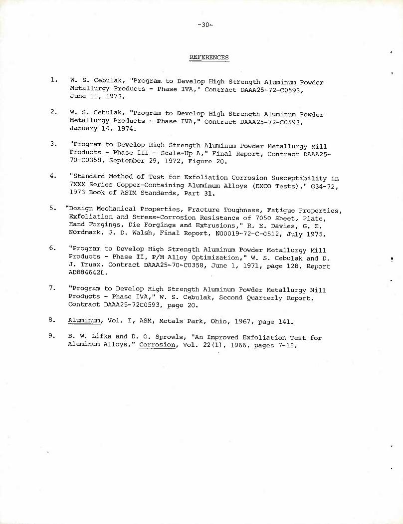
8.
■30-
REFERENCES
1. W. S. Cebulak, "Program to Develop High Strength Aluminum Powder Metallurgy Products - Phase IVA," Contract DAAA25-72-C0593, June 11, 1973.
2. W. S. Cebulak, "Program to Develop High Strength Aluminum Powder Metallurgy Products - Phase IVA," Contract DAAA25-72-C0593, January 14, 1974.
3. "Program to Develop High Strength Aluminum Powder Metallurgy Mill Products - Phase III - Scale-Up A," Final Report, Contract DAAA25- 70-C0358, September 29, 1972, Figure 20.
4. "Standard Method of Test for Exfoliation Corrosion Susceptibility in 7XXX Series Copper-Containing Aluminum Alloys (EXCO Tests)," G34-72, 1973 Book of ASTM Standards, Part 31.
5. "Design Mechanical Properties, Fracture Toughness, Fatigue Properties, Exfoliation and Stress-Corrosion Resistance of 7050 Sheet, Plate, Hand Forgings, Die Forgings and Extrusions," R. E. Davies, G. E. Nordmark, J. D. Walsh, Final Report, N00019-72-C-0512, July 1975.
6. "Program to Develop High Strength Aluminum Powder Metallurgy Mill Products - Phase II, P/M Alloy Optimization," W. S. Cebulak and D. J. Truax, Contract DAAA25-70-C0358, June 1, 1971, page 128. Report AD884642L.
7. "Program to Develop High Strength Aluminum Powder Metallurgy Mill Products - Phase IVA," W. S. Cebulak, Second Quarterly Report, Contract DAAA25-72C0593, page 20.
Aluminum, Vol. I, ASM, Metals Park, Ohio, 1967, page 141,
9. B. W. Lifka and D. 0. Sprowls, "An Improved Exfoliation Test for Aluminum Alloys," Corrosion, Vol. 22(1), 1966, pages 7-15.
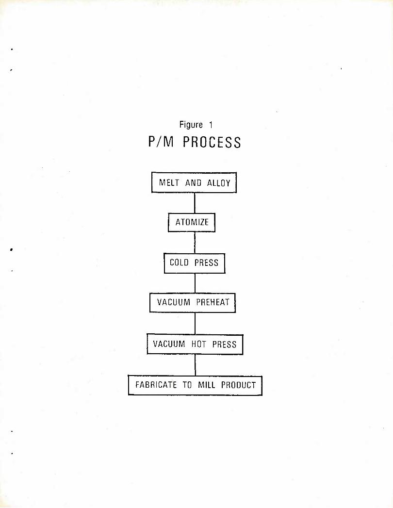
Figure 1
P/M PROCESS
MELT AND ALLOY
ATOMIZE
COLD PRESS
VACUUM PREHEAT
VACUUM HOT PRESS
FABRICATE TO MILL PRODUCT
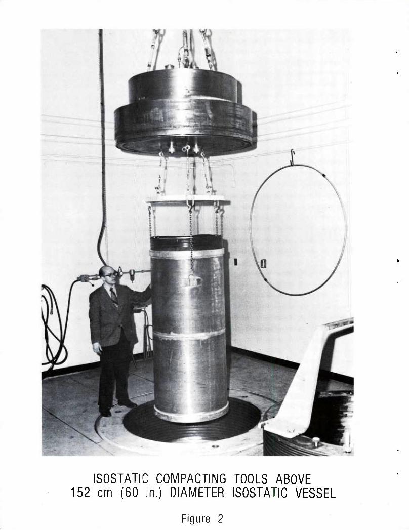
ISOSTATIC COMPACTING TOOLS ABOVE 152 cm (60 n.) DIAMETER ISOSTATIC VESSEL
Figure 2
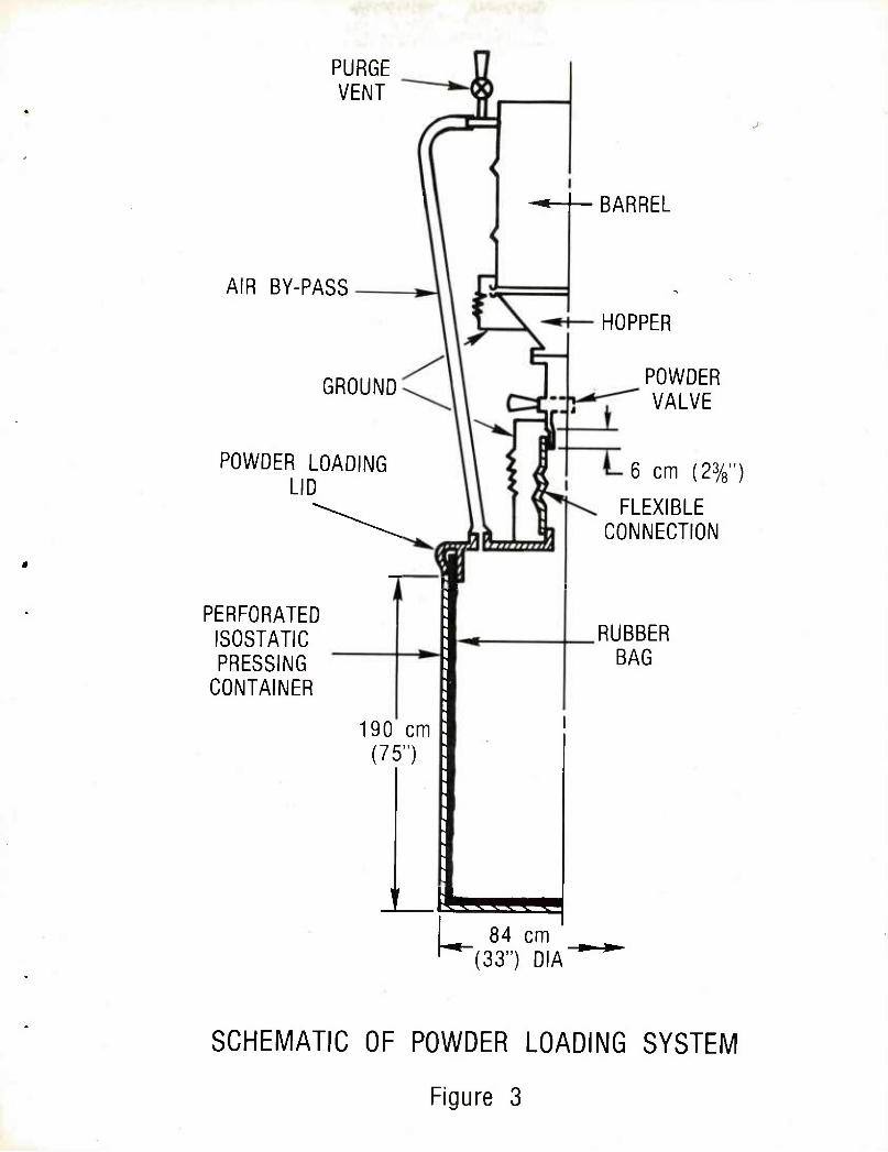
PURGE VENT
AIR BY-PASS
GROUND
POWDER LOADING LID
PERFORATED ISOSTATIC PRESSING
CONTAINER
li
-•-I— BARREL
190 cm (75")
-••-
gsgga ! 84 cm
"(33") DIA
HOPPER
POWDER VALVE
6 cm (23/8")
FLEXIBLE CONNECTION
RUBBER BAG
SCHEMATIC OF POWDER LOADING SYSTEM
Figure 3
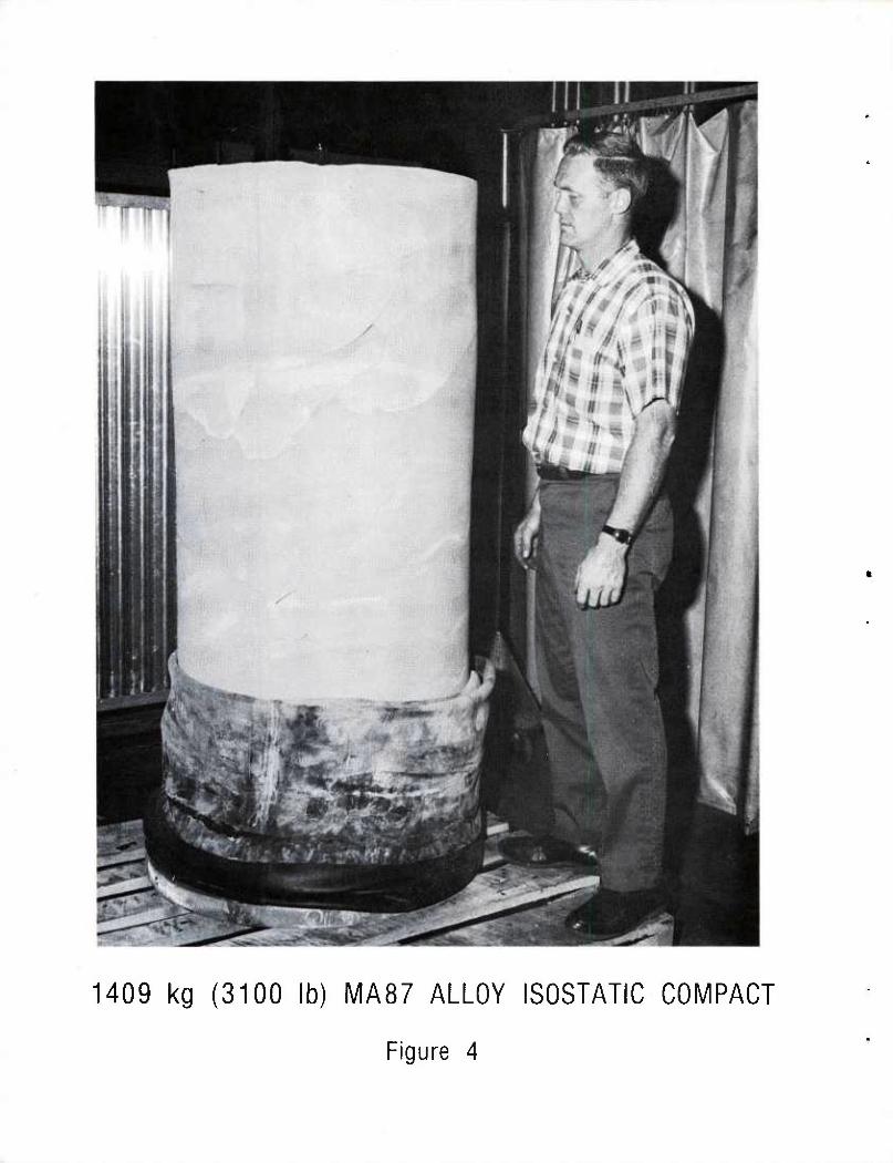
1409 kg (3100 lb) MA87 ALLOY ISOSTATIC COMPACT
Figure 4
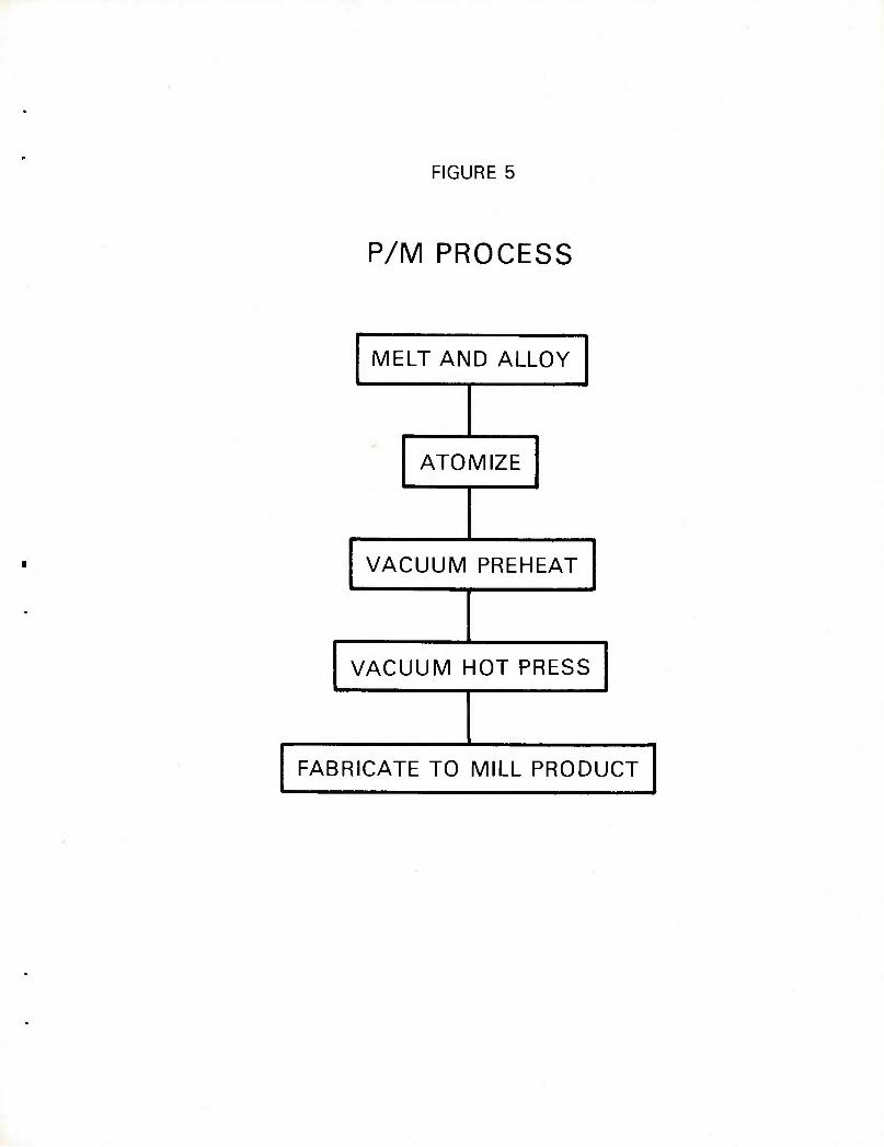
FIGURE 5
P/M PROCESS
MELT AND ALLOY
ATOMIZE
VACUUM PREHEAT
VACUUM HOT PRESS
FABRICATE TO MILL PRODUCT
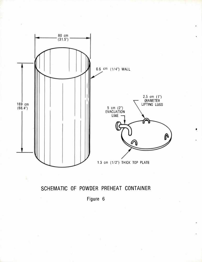
0.6 cm (1/4") WALL
5 cm (2") EVACUATION
LINE
2.5 cm (1") DIAMETER
LIFTING LUGS
1.3 cm (1/2") THICK TOP PLATE
SCHEMATIC OF POWDER PREHEAT CONTAINER
Figure 6
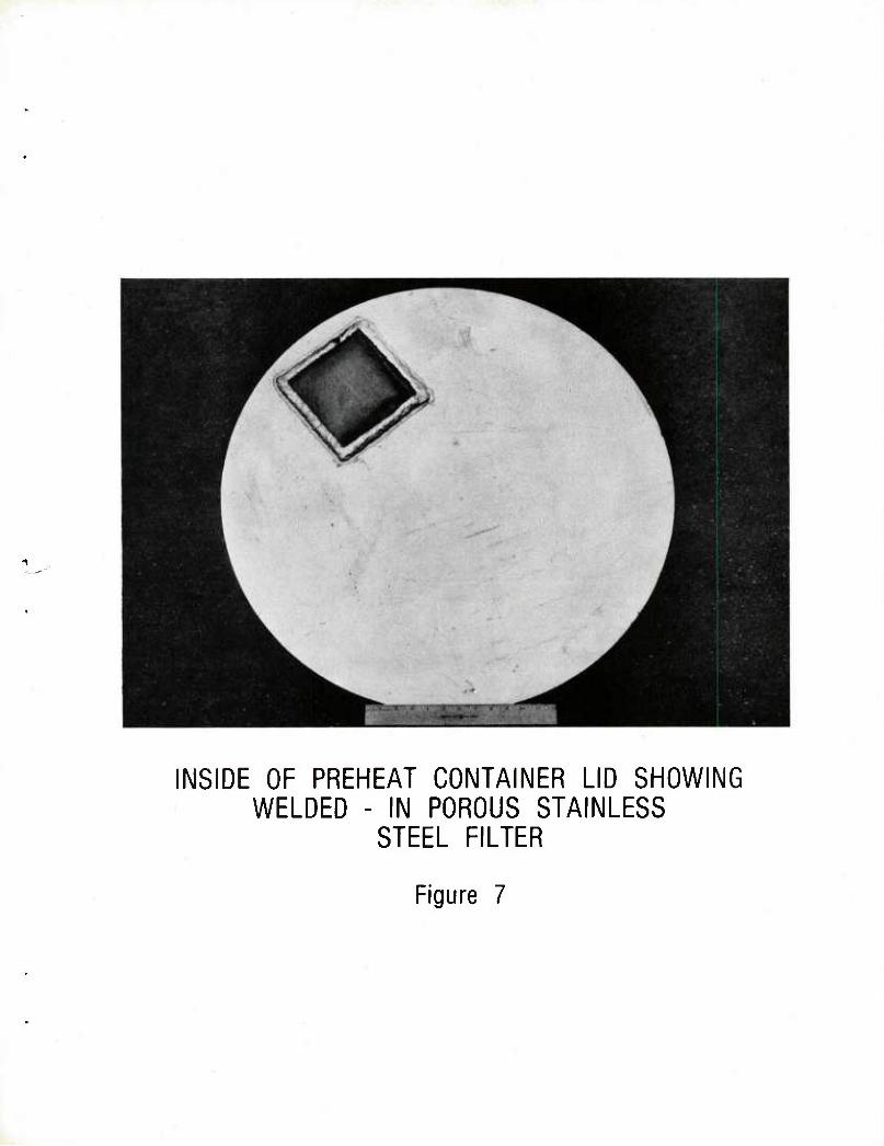
INSIDE OF PREHEAT CONTAINER LID SHOWING WELDED - IN POROUS STAINLESS
STEEL FILTER
Figure 7
PREHEAT CONTAINER POWDER LOADING SYSTEM
Figure 8
COMPLETE POWDER PREHEAT AND EVACUATION CONTAINER
Figure 9
z o
<
LU CL O
< LU X LU DC CD 0- T-
3 Z> U < > Li. o CJ
o CO
CD
05
ASSEMBLED VACUUM PUMPS SHOWING CONNECTIONS TO UNDER - CAR EVACUATION SYSTEM. CONTROL
PANELS AND LINES NOT SHOWN.
Figure 11
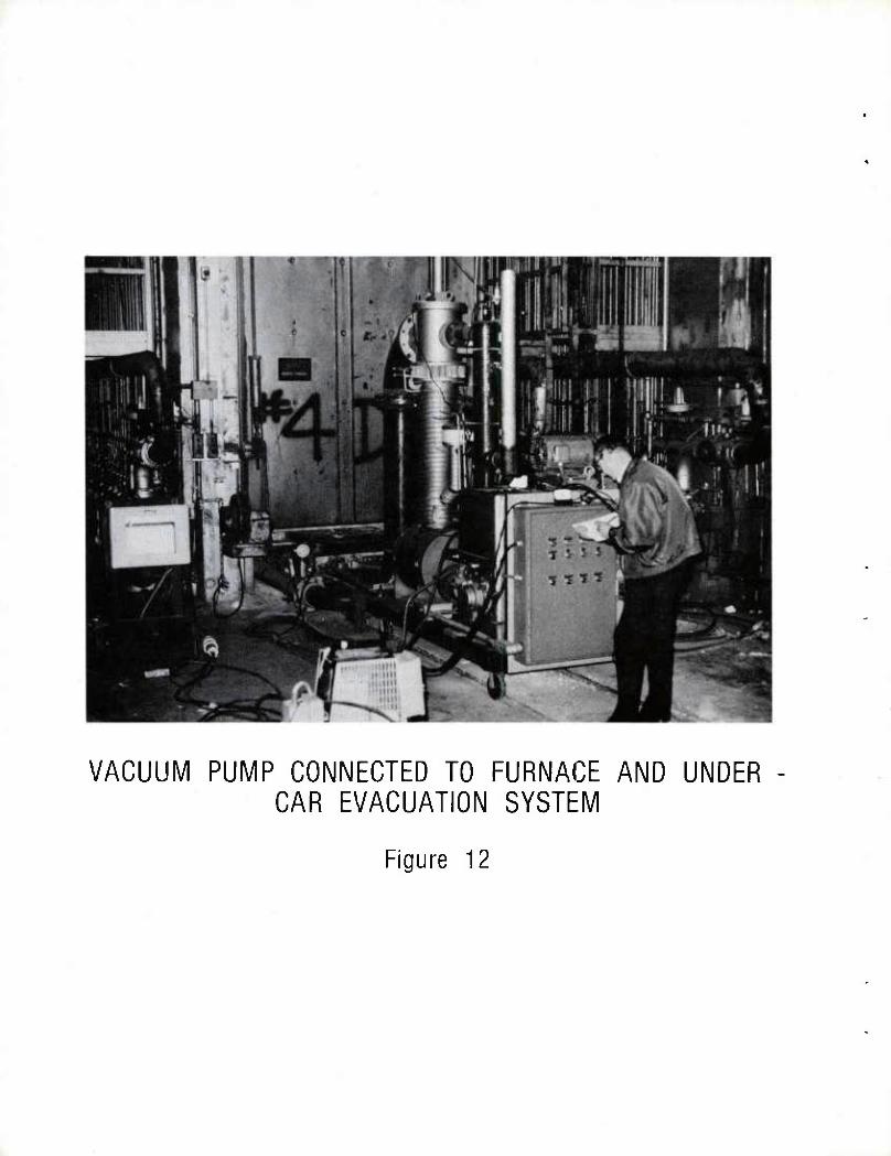
VACUUM PUMP CONNECTED TO FURNACE AND UNDER CAR EVACUATION SYSTEM
Figure 12
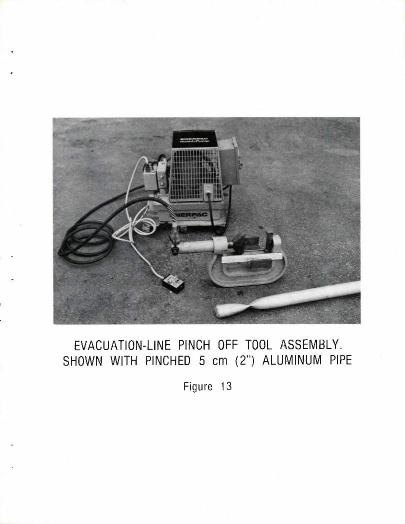
EVACUATION-LINE PINCH OFF TOOL ASSEMBLY. SHOWN WITH PINCHED 5 cm (2") ALUMINUM PIPE
Figure 13
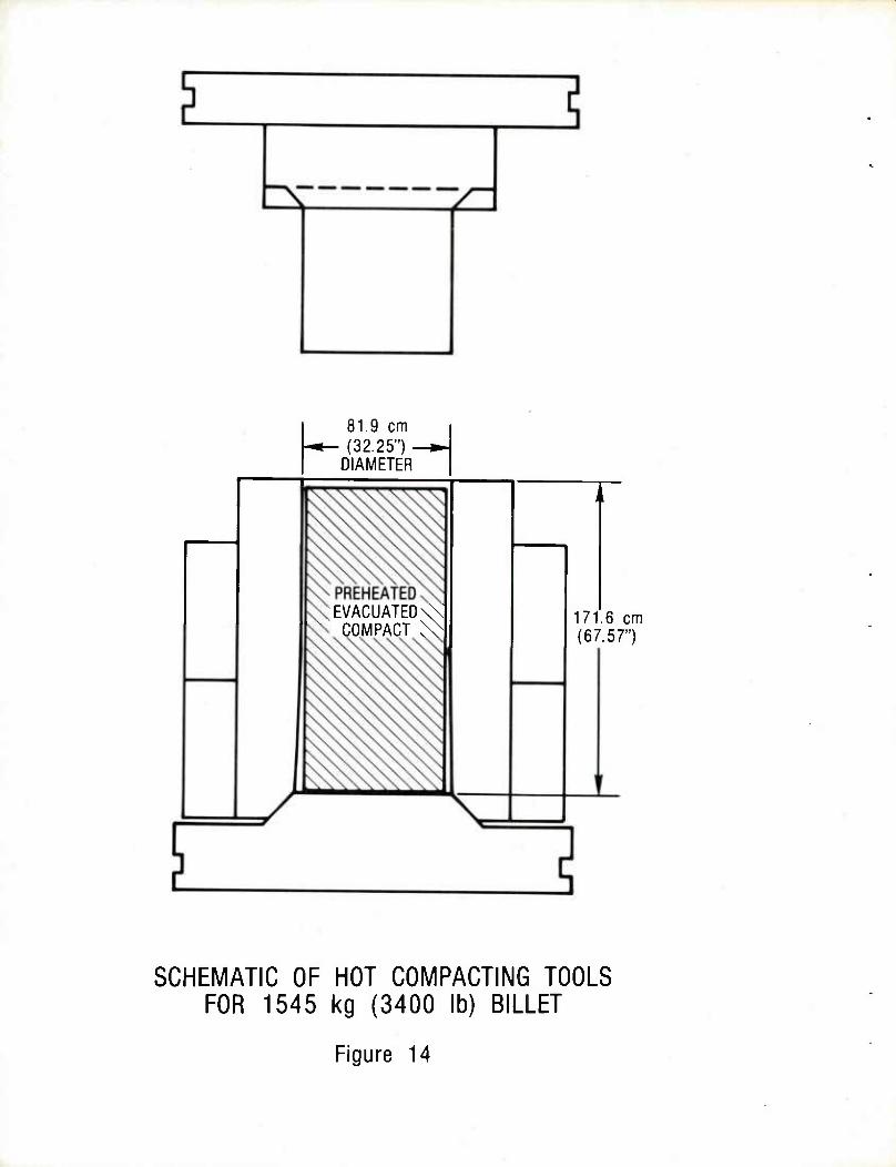
h 81.9 cm (32.25") -
DIAMETER
PREHEATED EVACUATED'
COMPACT 171.6 cm (67.57")
SCHEMATIC OF HOT COMPACTING TOOLS FOR 1545 kg (3400 lb) BILLET
Figure 14
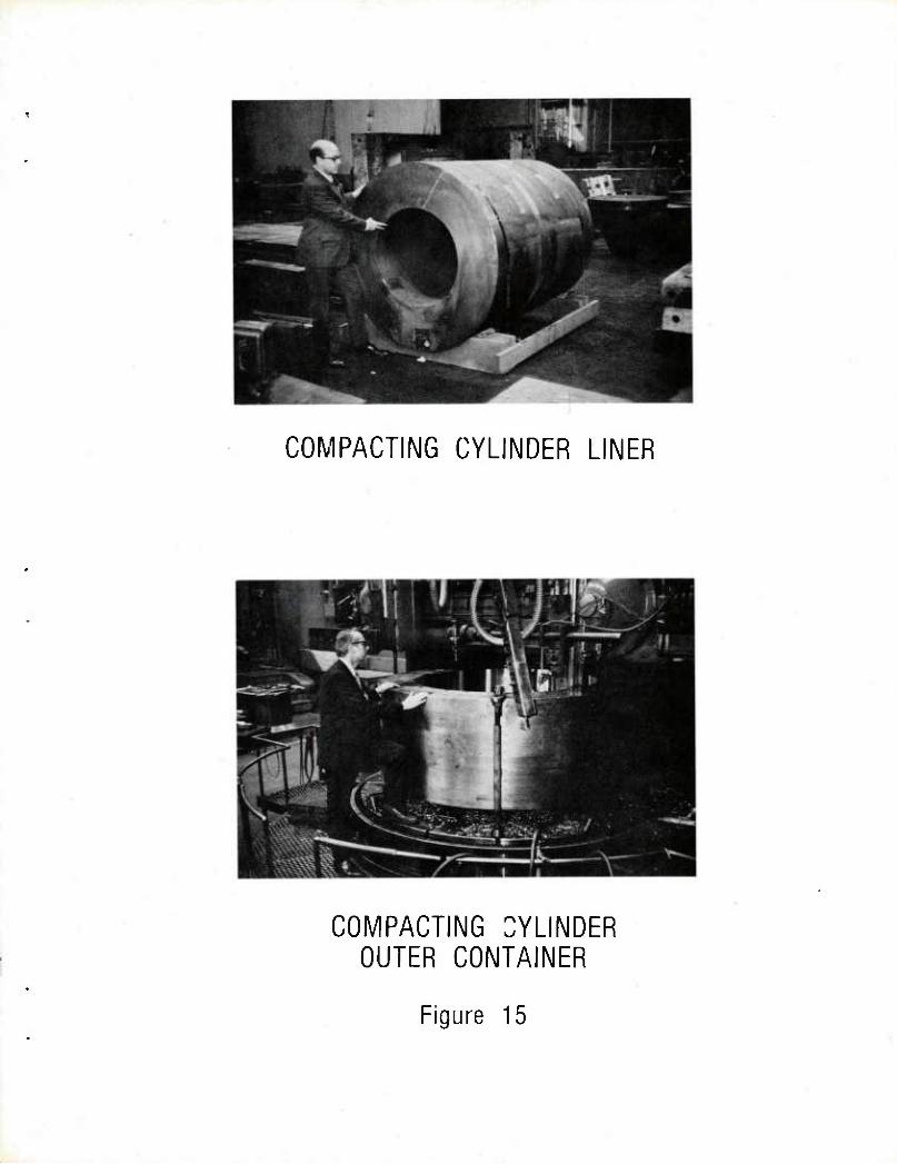
COMPACTING CYLINDER LINER
COMPACTING CYLINDER OUTER CONTAINER
Figure 15
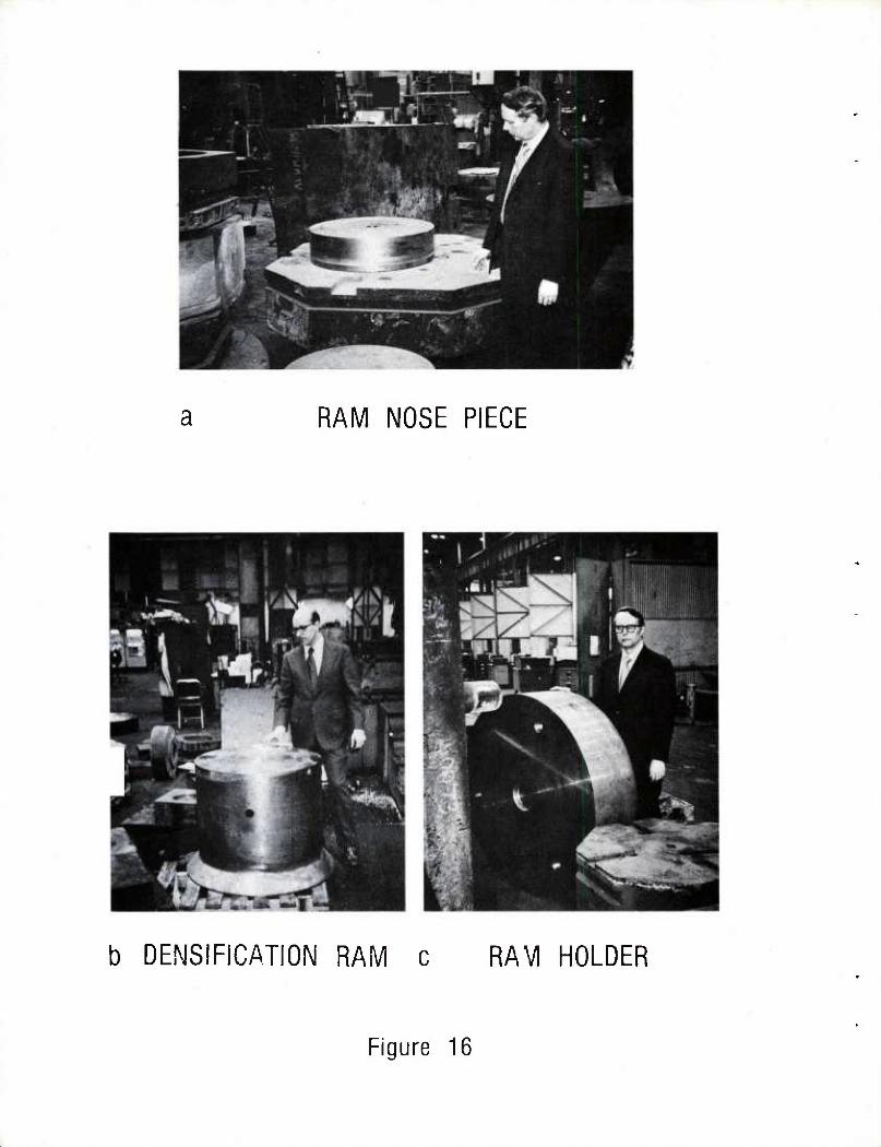
RAM NOSE PIECE
b DENSIFICATION RAM c RAVI HOLDER
Figure 16
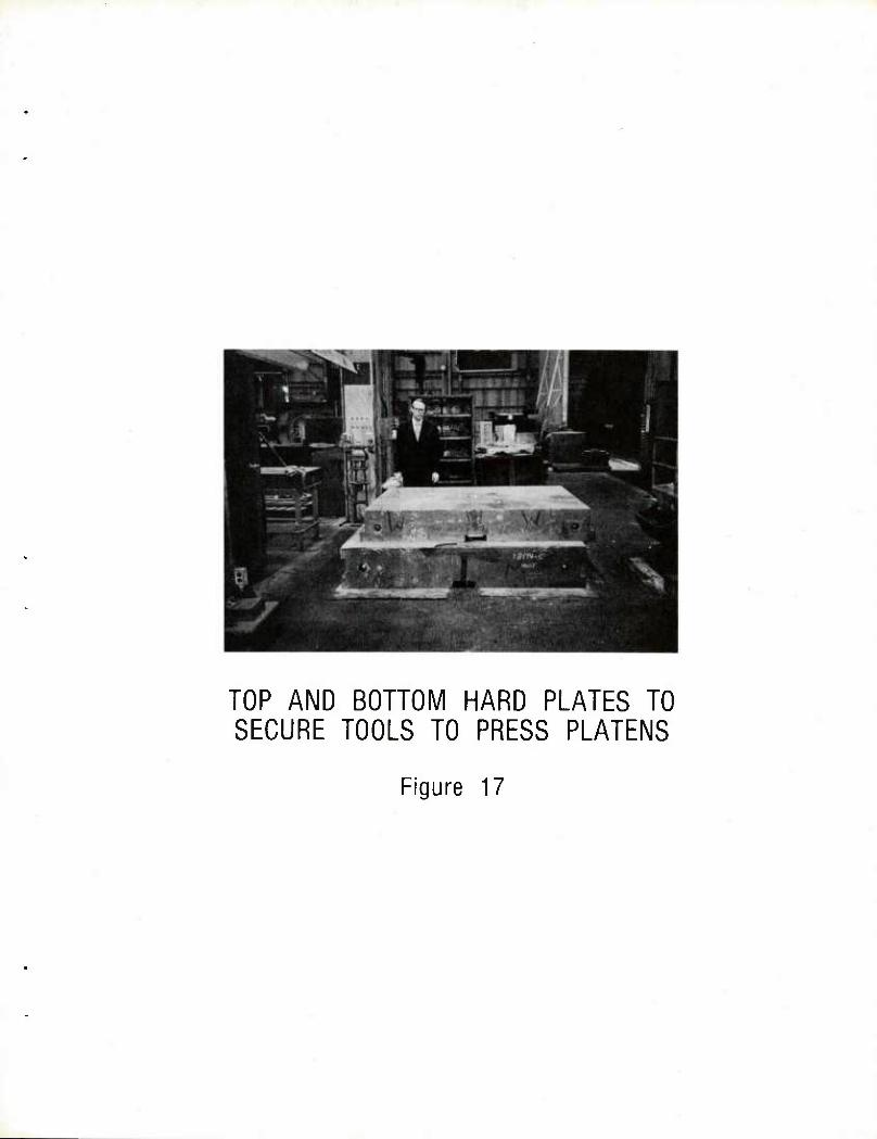
TOP AND BOTTOM HARD PLATES TO SECURE TOOLS TO PRESS PLATENS
Figure 17
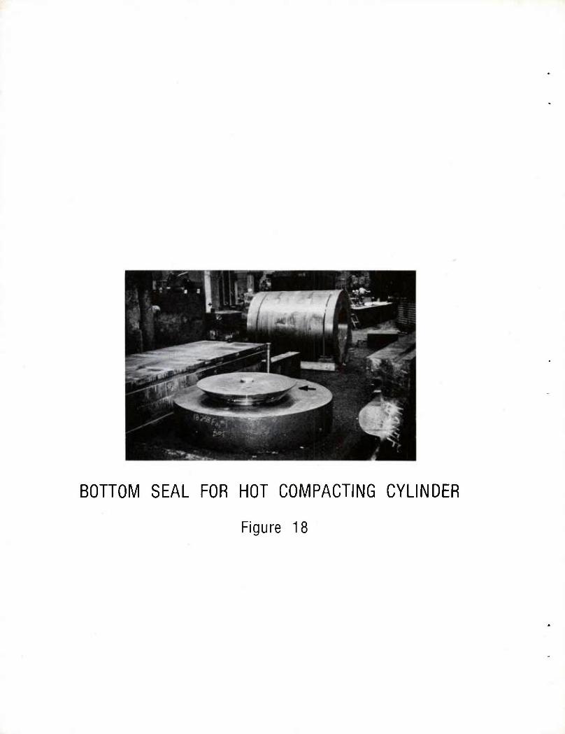
BOHOIVI SEAL FOR HOT COMPACTING CYLINDER
Figure 18
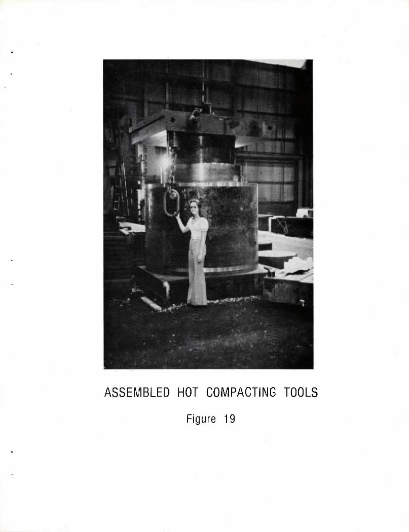
ASSEMBLED HOT COMPACTING TOOLS
Figure 19
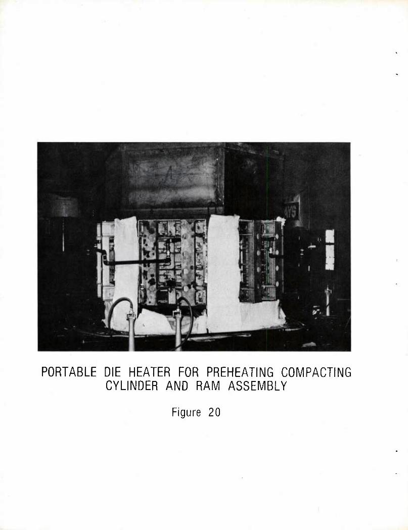
PORTABLE DIE HEATER FOR PREHEATING COMPACTING CYLINDER AND RAM ASSEMBLY
Figure 20
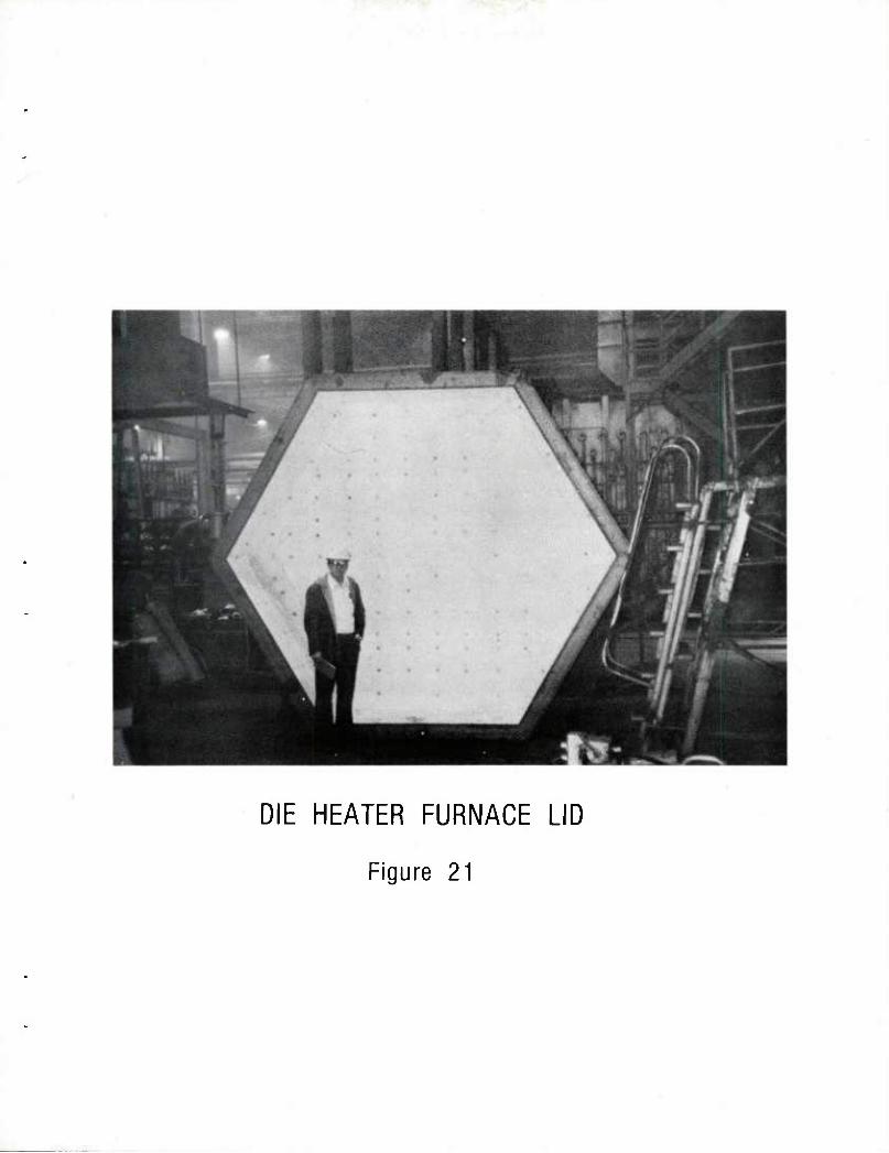
DIE HEATER FURNACE LID
Figure 21
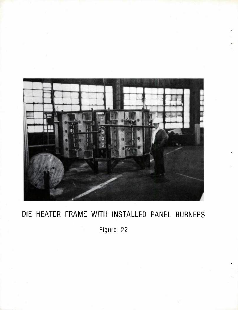
DIE HEATER FRAME WITH INSTALLED PANEL BURNERS
Figure 22
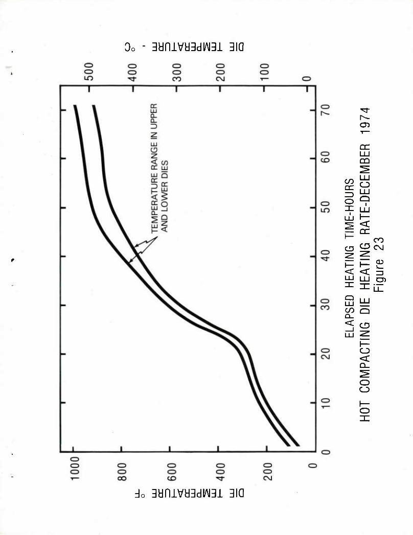
3dniVa3dlAI31 310
05
cr LU □Q
r1- i i i
o 9 ,-LJ L-r — DC
CO CD ^ eg
03
O)
l— i—
< < LU MJ
CO Q
< CD
O < Q_
O O
do 3anivy3diAi3i 3ia
HEATING LOWER BASE PLATE - CYLINDER SEAL ASSEMBLY
Figure 24
Oo-3aniva3di/\i3i
o O LO
jl o ^ o —) ^-r ^ cr bz o
< >
CZ5 o CO
o CZ3 eg
o CZ5
T ^J-
CZJ h- r--
o LU Q
C3 1
CO CO QC
CD UO
C5
i— =5 O
i
O < CO ^
LU DC Q-
CvJ
O O
<
DC LU
o Q_
DC O
uo C\J
CD
h- <
<
CZ5 O O CD C3 CD CD CD o CO CZ3 C3 CD O CD CD CO CD CD CD CZ) CT> OO r— CO LO ^r co CVJ
3anivd3di/\i3i
LOWERING BASE - LOWER SEAL ASSEMBLY TO LOWER PLATEN OF PRESS TO INITIATE
TOOL INSTALLATION IN 311 MN (35,000 T) PRESS
Figure 26
LIFTING DIE HEATER ZURNACE LID FROM FURNACE FRAME
Figure 27
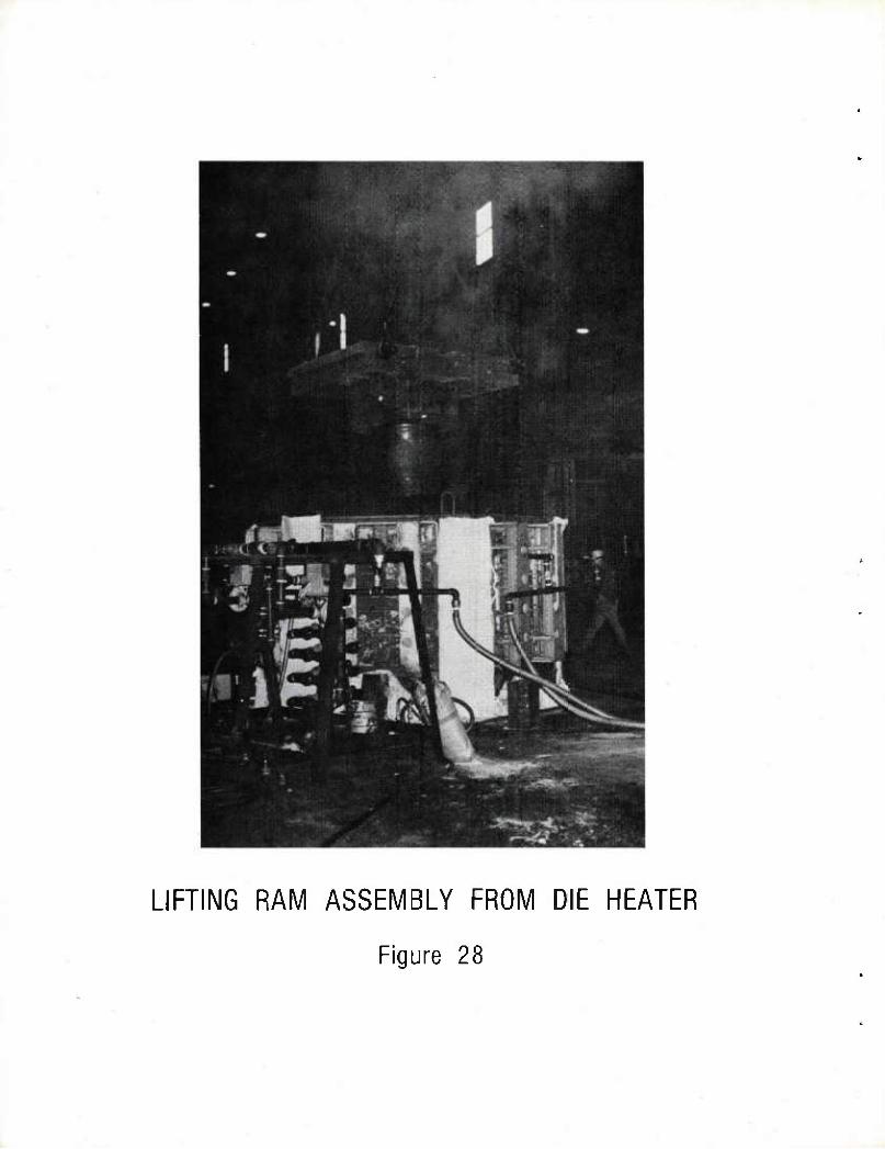
LIFTING RAM ASSEMBLY FROM DIE HEATER
Figure 28
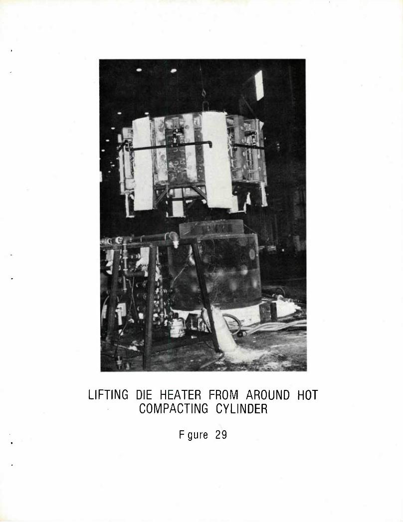
LIFTING DIE HEATER FROM AROUND HOT COMPACTING CYLINDER
Fgure 29
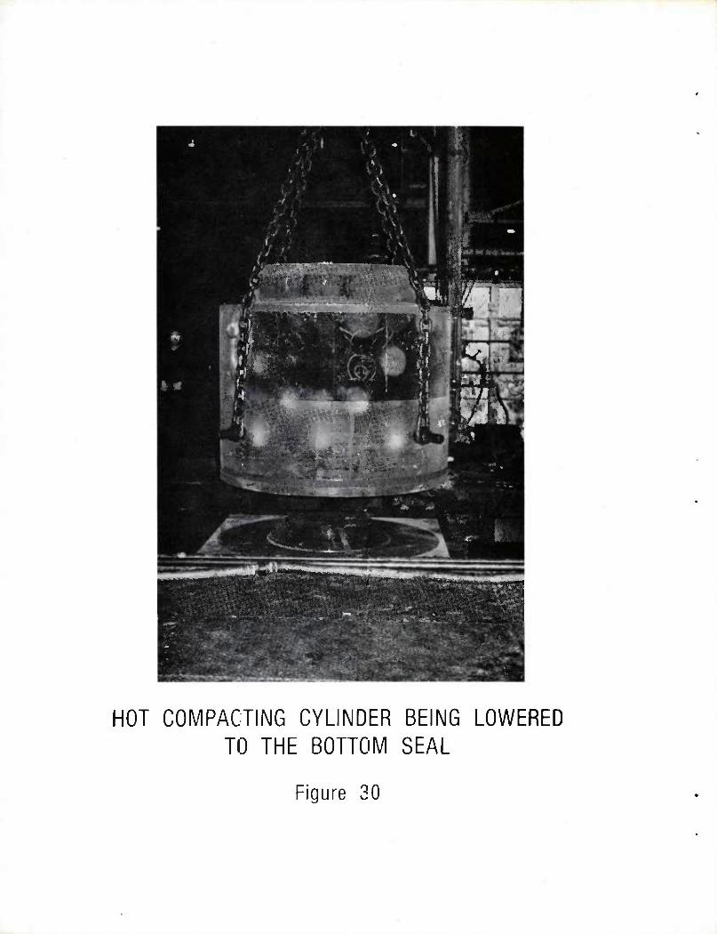
*
•
■ ts
HP' » - 1 M
1 te ^ -p y
Hi - 3 ,♦ # 1mm s ^y
f3 .' ,
Ws .;■;
m J
u j •
mZg.^ - - ^^^ t,, " r:-'
^^— —^i' * %■»"
•,. --^ 1 ^^^J3S-"*^
yjg ■
•3p>( ViiftUi^ilN
r -■
pwiiiiiiBt, ;»<*»*»
■ ■■.. ■■■.■ ■■■■: . ■■■ . '
~':'J^€^"
:«*:S-:l; ^ - J,«3^
HOT COMPACTING CYLINDER BEING LOWERED TO THE BOTTOM SEAL
Figure 30
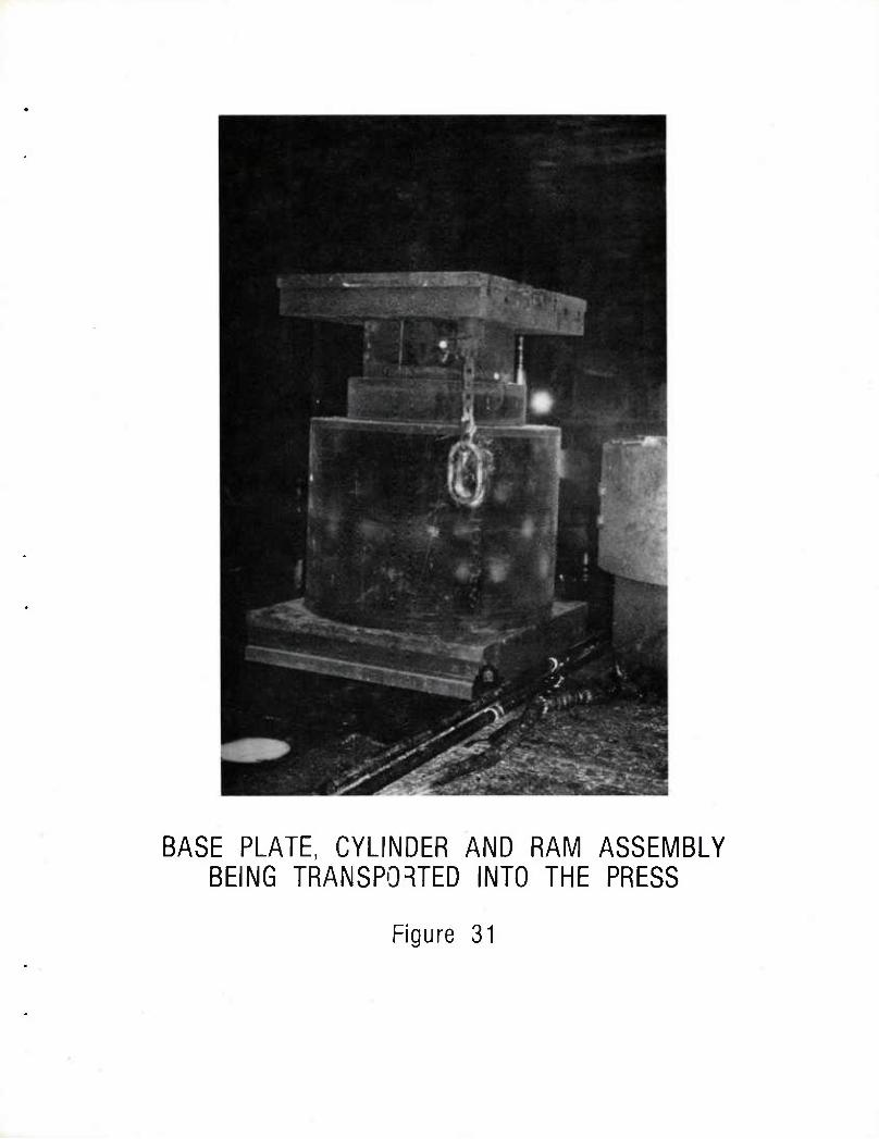
BASE PLATE, CYLINDER AND RAM ASSEMBLY BEING TRANSPORTED INTO THE PRESS
Figure 31
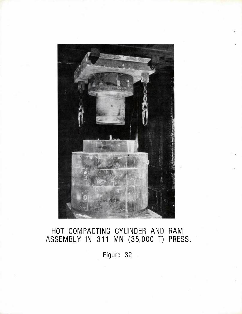
HOT COMPACTING CYLINDER AND RAM ASSEMBLY IN 311 MN (35,000 T) PRESS,
Figure 32
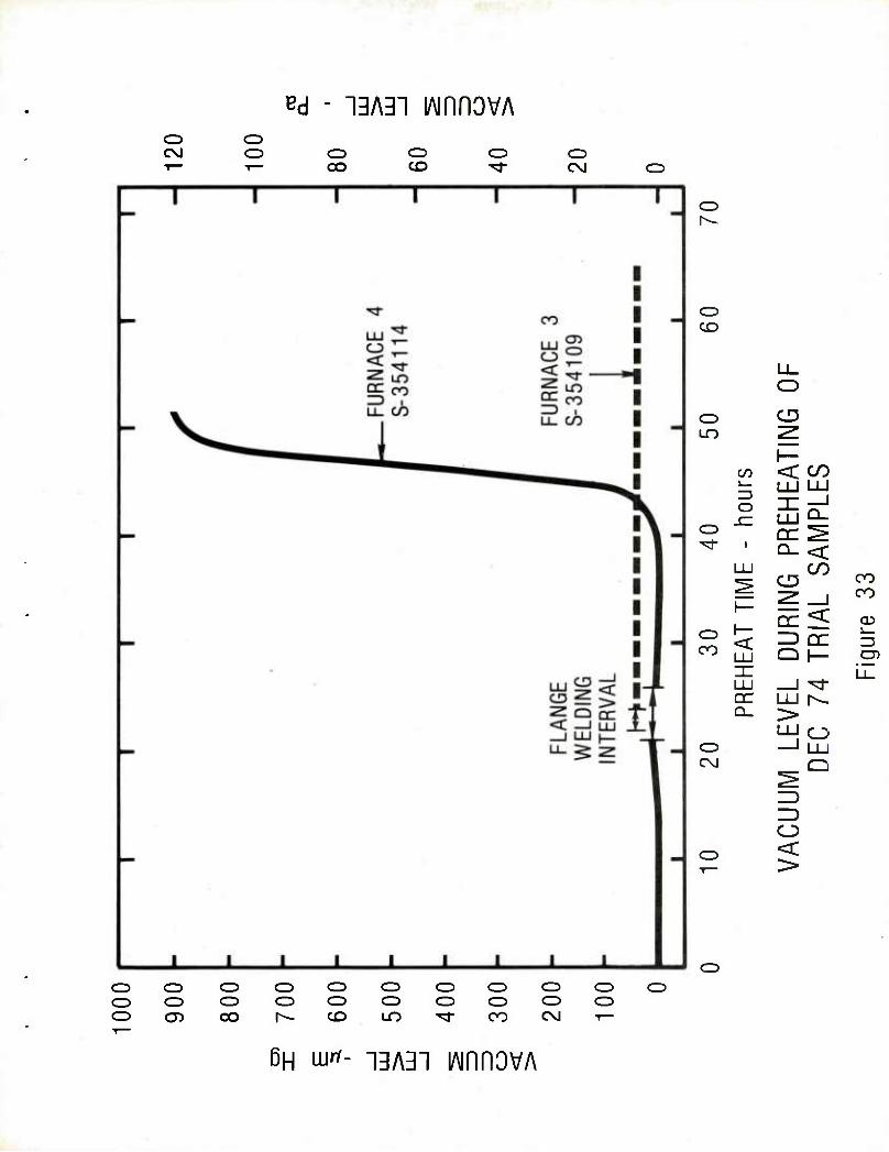
^d - 13A31 lAinnovA o CM
o o CD
oo CD CO
o C\J
CZ)
cz> CO
Ll_ O
o CD in
P CO < CO i— LU LU 13 o _J (— LU Q_
CD DC ̂ ^r LU
Q_ < CO
P CD OO
_l CO
□c < CD CD h-
DC Z3 co LU Q h- CD i i
LU _J "3" QC LU r^ Q_ >
LU o CD 1 LU CM
<
Q
o o o CO co CO co CO CO CO o CO CO o o CO CO CO CO CO CD O) oo r^- CO LO "d- CO CM 1—
6H \urt- ngAgn lAinHOVA
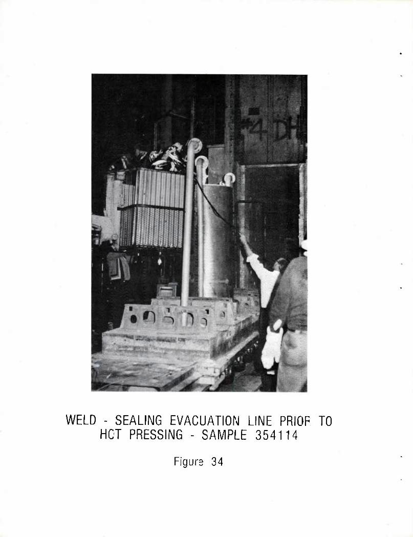
WELD - SEALING EVACUATION LINE PRIOF TO HCT PRESSING - SAMPLE 354114
Figure 34
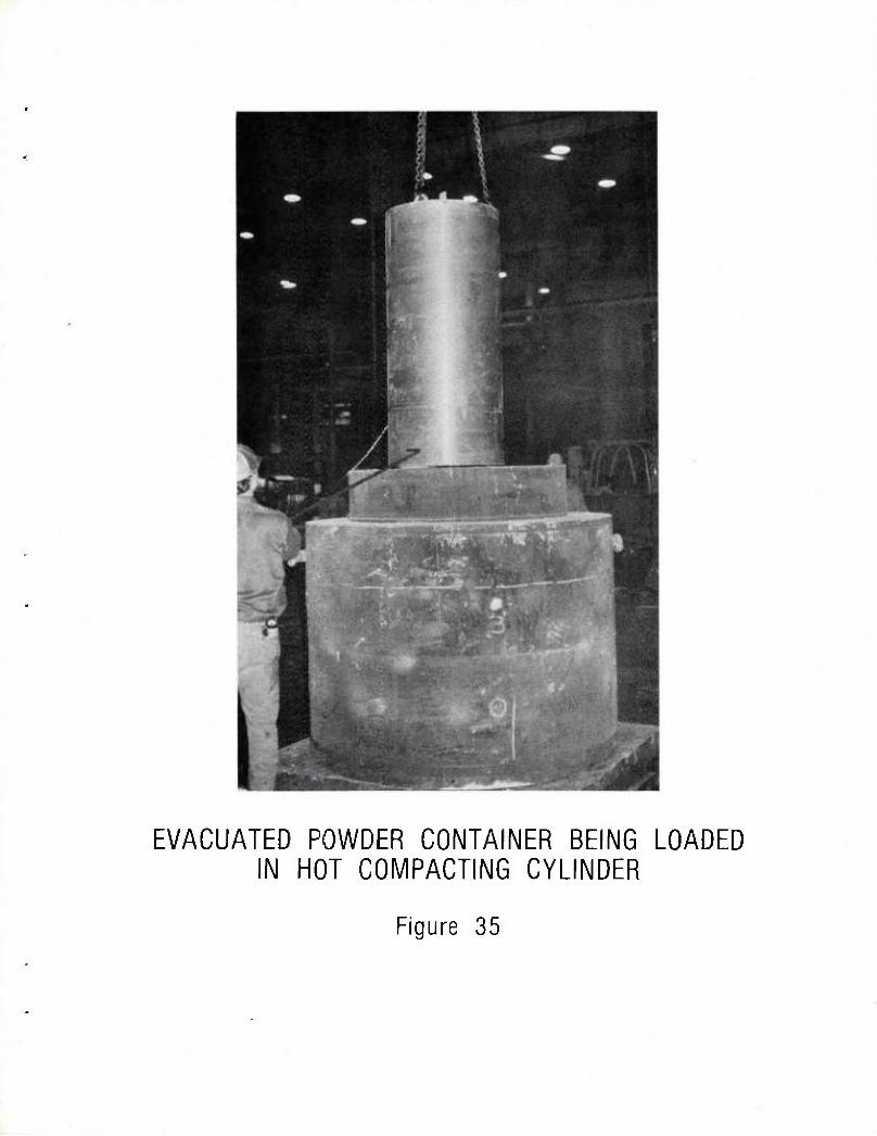
EVACUATED POWDER CONTAINER BEING LOADED IN HOT COMPACTING CYLINDER
Figure 35
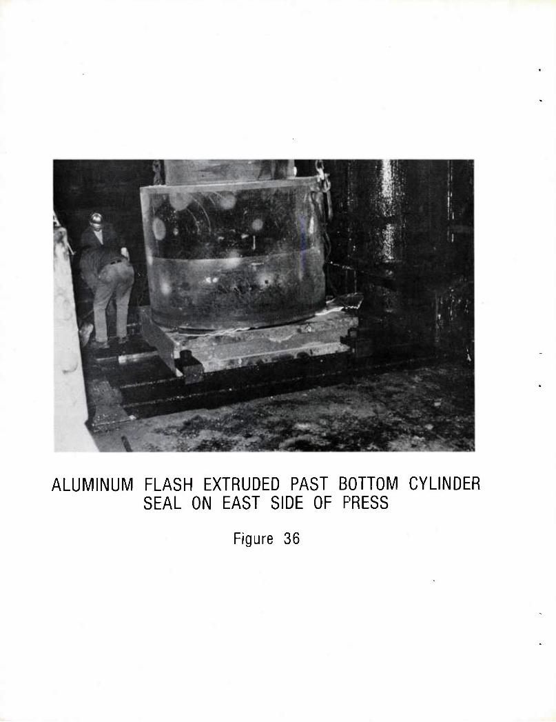
ALUMINUM FLASH EXTRUDED PAST BOTTOM CYLINDER SEAL ON EAST SIDE OF PRESS
Figure 36
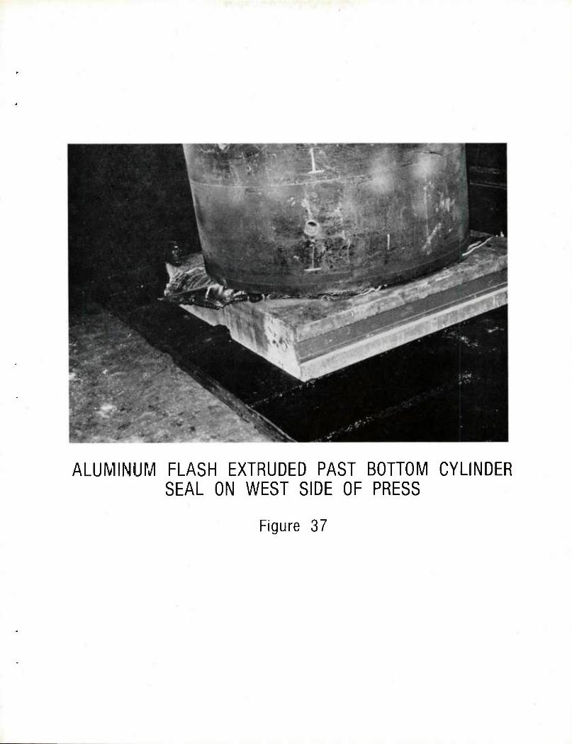
ALUMINUK/l FLASH EXTRUDED PAST BOTTOM CYLINDER SEAL ON WEST SIDE OF PRESS
Figure 37
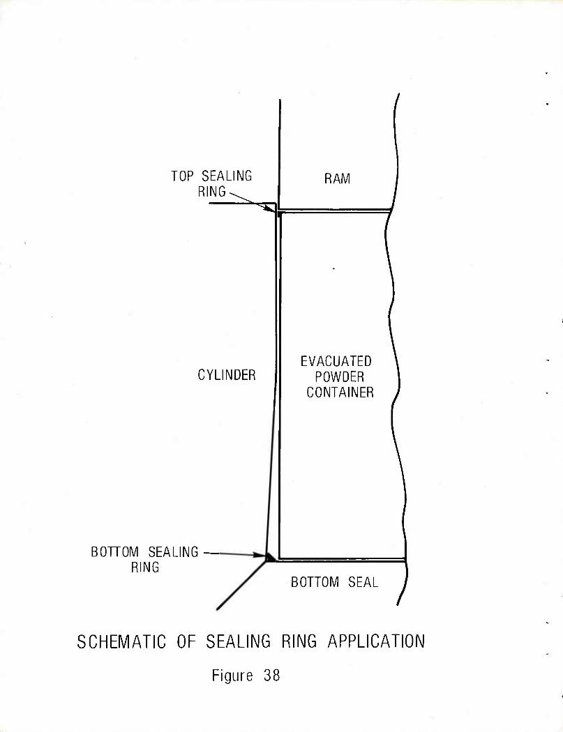
TOP SEALING RING^
^53
CYLINDER
RAM
BOTTOM SEALING — RING
EVACUATED POWDER
CONTAINER
BOTTOM SEAL
SCHEMATIC OF SEALING RING APPLICATION
Figure 38
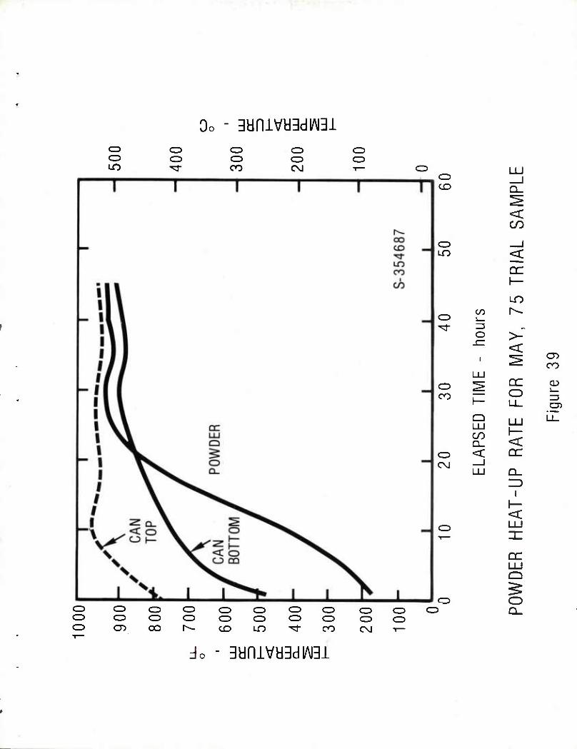
3ynivy3diAi3i o o
o CO
C3 CD C\J
CD
C3 O O CZ) C=) CD C3 o o cz> CD C3 O C3 o o o o C3 o CD 05 CO r-- CO LO ^d- CO C\J t—
LU cz> 1 CO
< CO
o —I LO <
1—
CO r^ CD ^d- 3 „
o >- -£Z
< 1 ^
05 CO
LU
o ^ DC o Ll_
CD
CO h- 05
Q II1 CO n
LU
<
Ll_
o < DC C\J _l
LU Q_
1 1— <
C3 LU
DC LU Q
CD >
o Q_
3yniva3di/\i3i
POWDER PREHEAT CONTAINERS WITH EVACUATION LINE BEING PINCHED CLOSED PRIOR TO WELD-SEALING
Figure 40
EJECTED BILLET UNDER SUSPENDED CYLINDER EJECTION SPACER RING IS SHOWN ON
BOTTOM HARD PLATE
Figure 41
VACUUM PUMP AND FURNACE CAR ASSEMBLY WITH THREE POWDER CONTAINERS FOR PREHEATING
Figure 42
FRONT FRONT
#3 DIE HEATER #4 DIE HEATER
ARRANGEMENT OF POWDER CONTAINERS FURNACES FOR PREHEATING
Figure 43
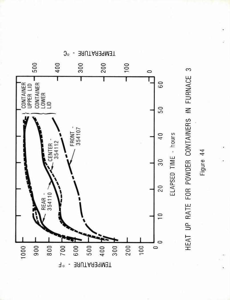
3aniva3diAi3i CD O LO
O O
CD o CO
o CD
CD CD
o CD
CO
<
or
CD LO
CO
LU CD CO ^
'^- =3 < O 1— .c "^
1 o ^r o ^r LU
CO P DC LU Q
=3
UJ CO O
Q_
LL
CD < C\J _i DC
CD
LU O Ll_
LU
< DC
O O CD CD CD CD CD CD C3 CD CD O O C3 CD CD CD CD CD CD CD OJ OO r^- CD LO ^3- CO CM -r-
3anivy3diAi3i
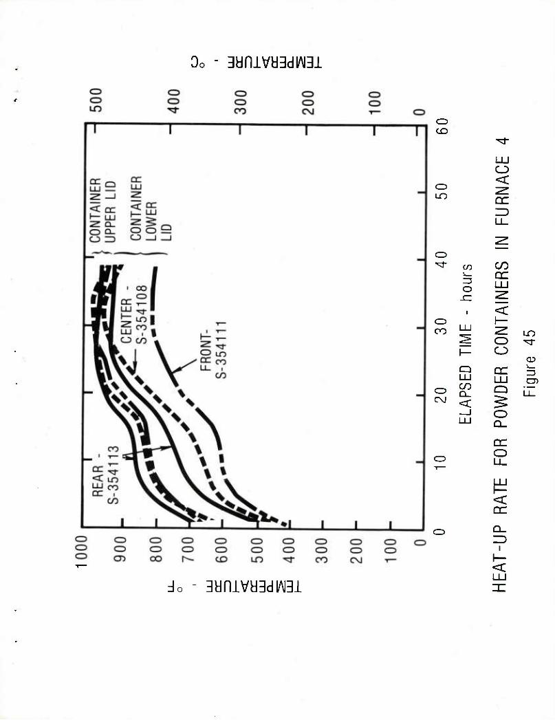
3yniva3di/\i3i
o CD
LU o <
LO DC
Ll_
CD ^r CO CO
I DC Z3 o
1
LU
< CD h- CO LU Z^ uo
^ o ^d- 1— o
CD Q DC Z3 LU LU O)
CD CO Q Li_ C\J < ^
—1 O LU Q_
DC O
Q_
i I— <
3yniva3di/\i3i
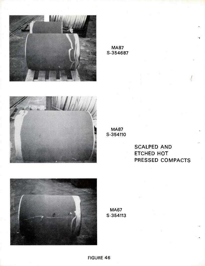
MA87 S-354687
MA87 S-354110
SCALPED AND ETCHED HOT PRESSED COMPACTS
MA67 S-354113
FIGURE 46
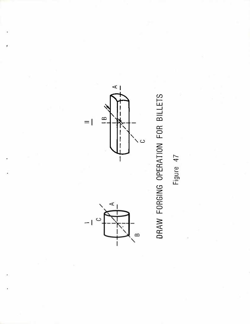
= 1
^s
<l
\ I
\ I ' I l
\o
I
-I
CO
DC O
< DC
Q_ O
CD
CD DC O
< DC Q
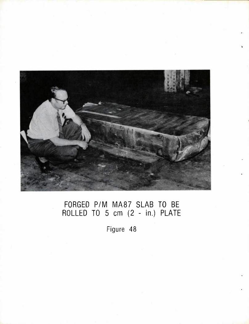
FORGED P/M MA87 SLAB TO BE ROLLED TO 5 cm (2 - in.) PLATE
Figure 48
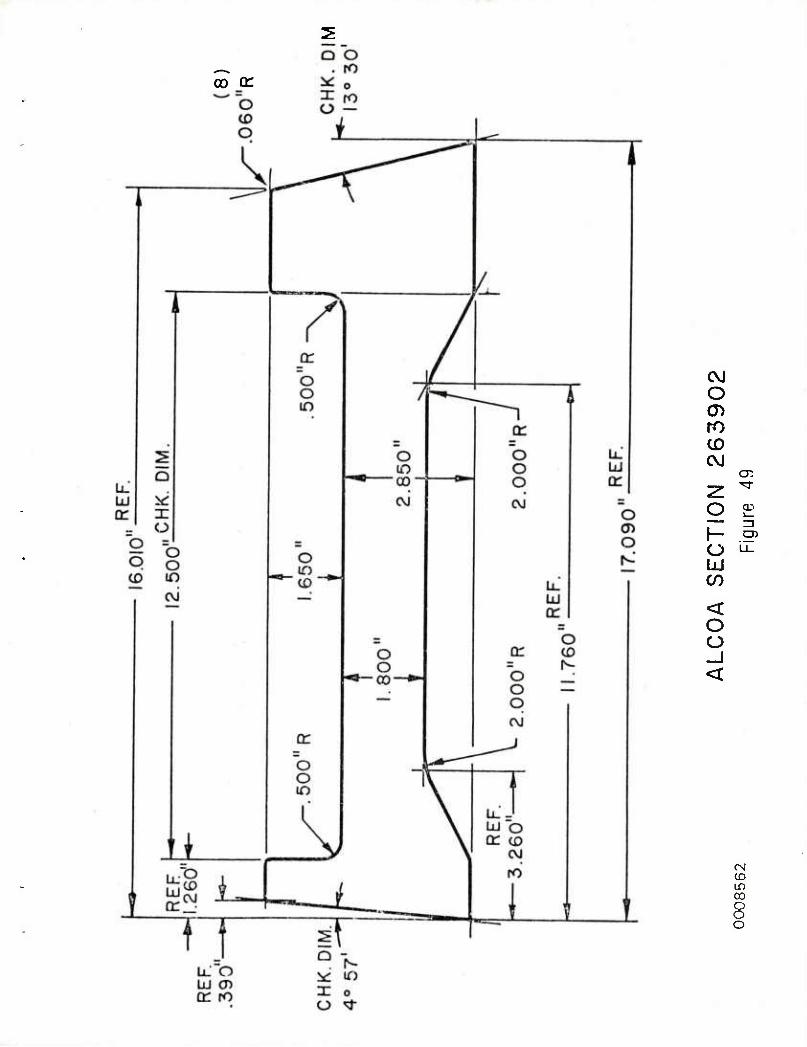
oo tr
<\J O
ro CD CVJ
a: z ^r
o 03 — —1 1- CD
o LJ_
LU CO
< o o
CM CD LD CO
8
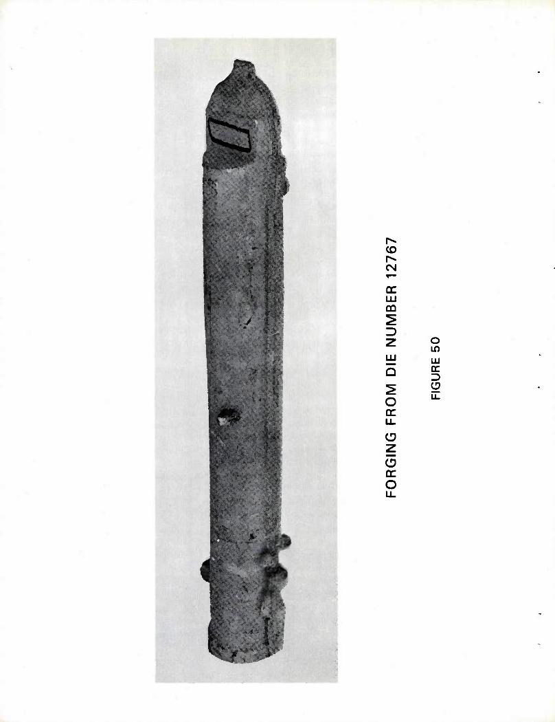
CD
CN
CQ
z UJ
Q
O DC
O IT)
LU cc
CD
DC O
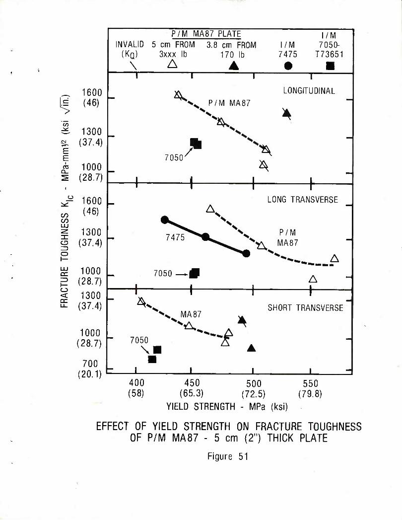
E E
i 03
Q_
CO CO
o
< DC
1600 (46)
1300 (37.4)
1000 (28.7)
1600 (46)
1300 (37.4)
1000 (28.7)
1300 (37.4)
1000 (28.7)
700 (20.1)
P/M MA87 PLATE l/M INVALID 5 cm FROM 3.8 cm FROM l/M 7050-
(KQ) 3xxx lb 170 lb 7475 T73651
\ A A • ■ 1 I 1 1
^ P/M MA87 LONGITUDINAL
—
xv A x^
7050/ '^
^ ^
1 1 1 | 1 1 1 1 LONG TRANSVERSE
^ A\
~ 7475^S^^ \ P/M MA87
A
l
7050 ^P I i
A L 1 1 1
' V SHORT TRANSVERSE" >v MA 87 ^
"A A ^ 7050 ^ . -
\B A ■ i 1 1 1
400 450 500 550 (58) (65.3) (72.5) (79.8)
YIELD STRENGTH - MPa (ksi)
EFFECT OF YIELD STRENGTH ON FRACTURE TOUGHNESS OF P/M MA87 - 5 cm (2") THICK PLATE
Figure 51
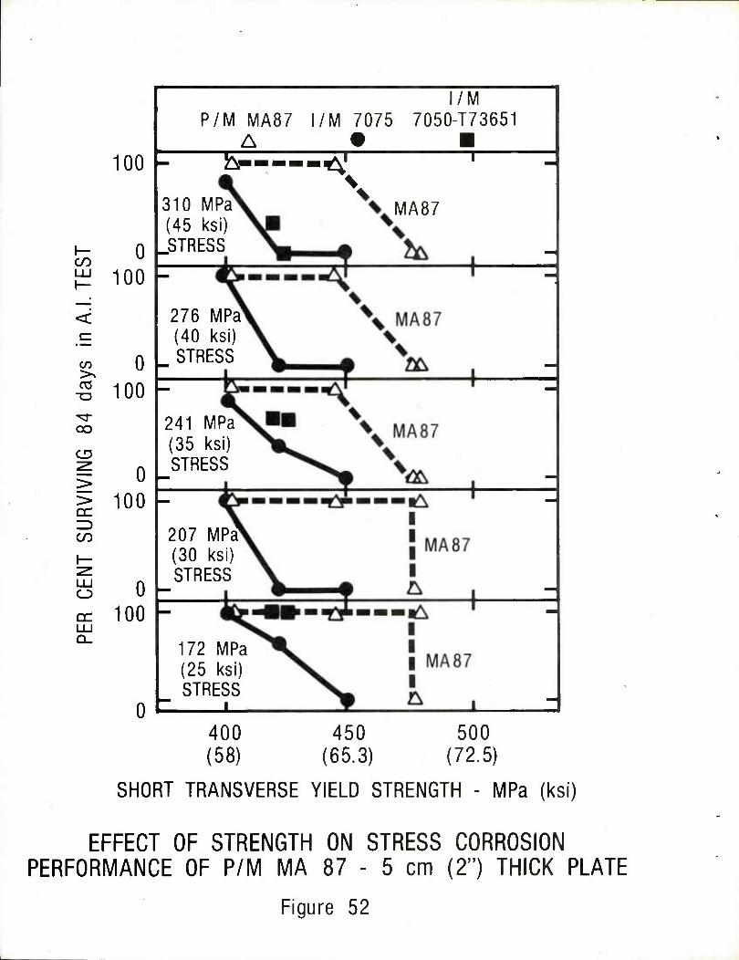
in
CO
CO
CD
CC
CO
I—
LU O
GC LU
100
0 100
0 100
0 100
0 100
0
310 MPa (45 ksi)
I STRESS
P/M MA87 A
l/M 7075 l/M
7050-T73651
fr-™-^ T
MA87
276 MPa (40 ksi) STRESS
241 MPa (35 ksi) STRESS
207 MPa (30 ksi) STRESS
172 MPa (25 ksi) STRESS
■
400 (58)
450 (65.3)
500 (72.5)
SHORT TRANSVERSE YIELD STRENGTH - MPa (ksi)
EFFECT OF STRENGTH ON STRESS CORROSION PERFORMANCE OF P/M MA 87 - 5 cm (2") THICK PLATE
Figure 52
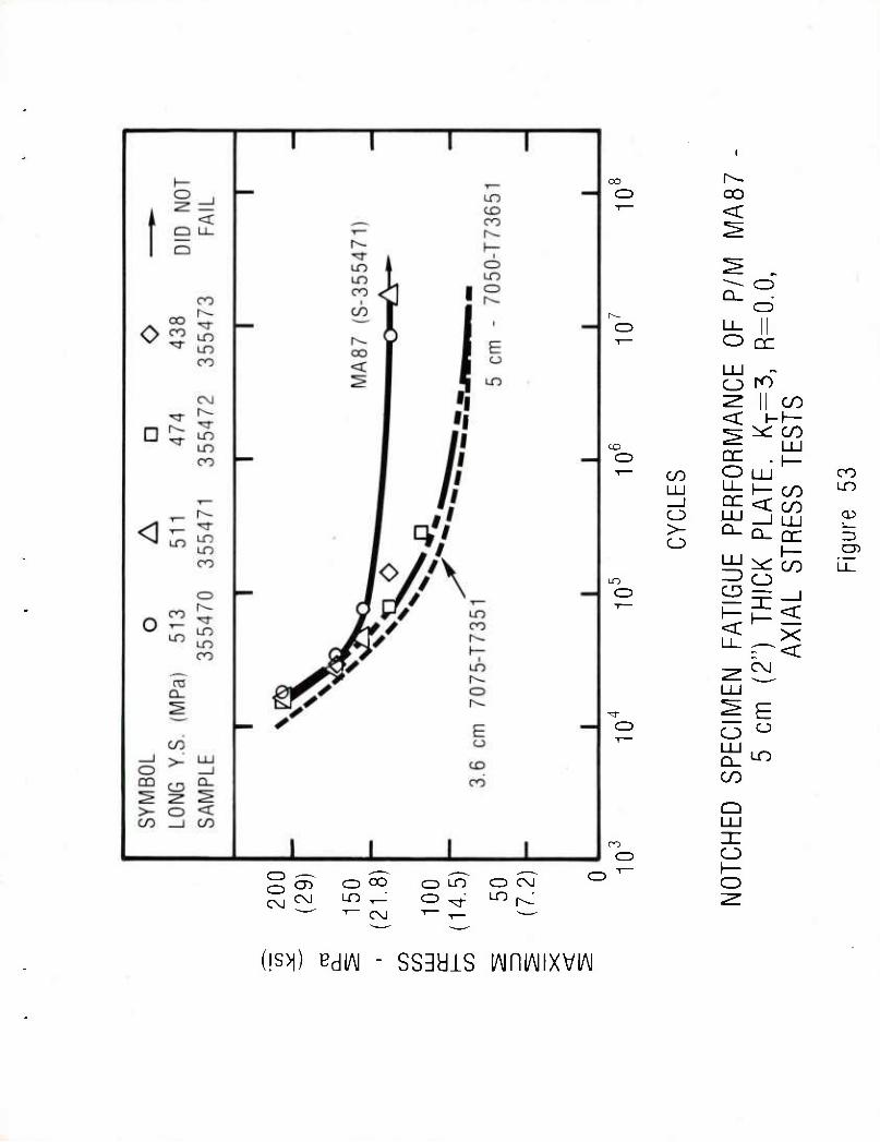
o (^ O oo 'l— <
CNJ
CD CvJ
CD OO in -,_ 1— CO
CD LO CD CM
CD t^-. CD u_
o LU o
CC
ro" CO
< i-h-
CO ^ CO
LU CD or . h- T CO o LU CO
LU LI- h- CO uo 1 DC < CO CJ LU 1 1 1 1 CD
>- o Q_ n cc =3
LU ^ h- CO i i
LO IZ) C3 O CD
1— < 11
LU
1—
C\J
1 <
X <
■^r ^ E C3 o
LU Q_ CO
Q LU
oo nz C=> o
h- o LO r^-
(!S>1) BdlAI - SSBdlS lAiniAIIXVIAI
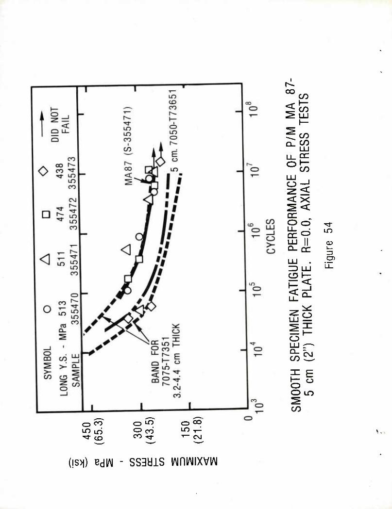
I
CO en \— CO
~ CO Q_ C/D
LJ_0C o J—
CO
i< <x ^< DC Oo
Q-CC
un
i_ =3
o
o
CO C\J
O LO
CO
cz> CO LO LO "'d" CO
C3 LO ^ CO CD CO LO ^ co^- 1— C\J
(!S>1) BdlAI - SS^diS lAiniAIIXVIAI
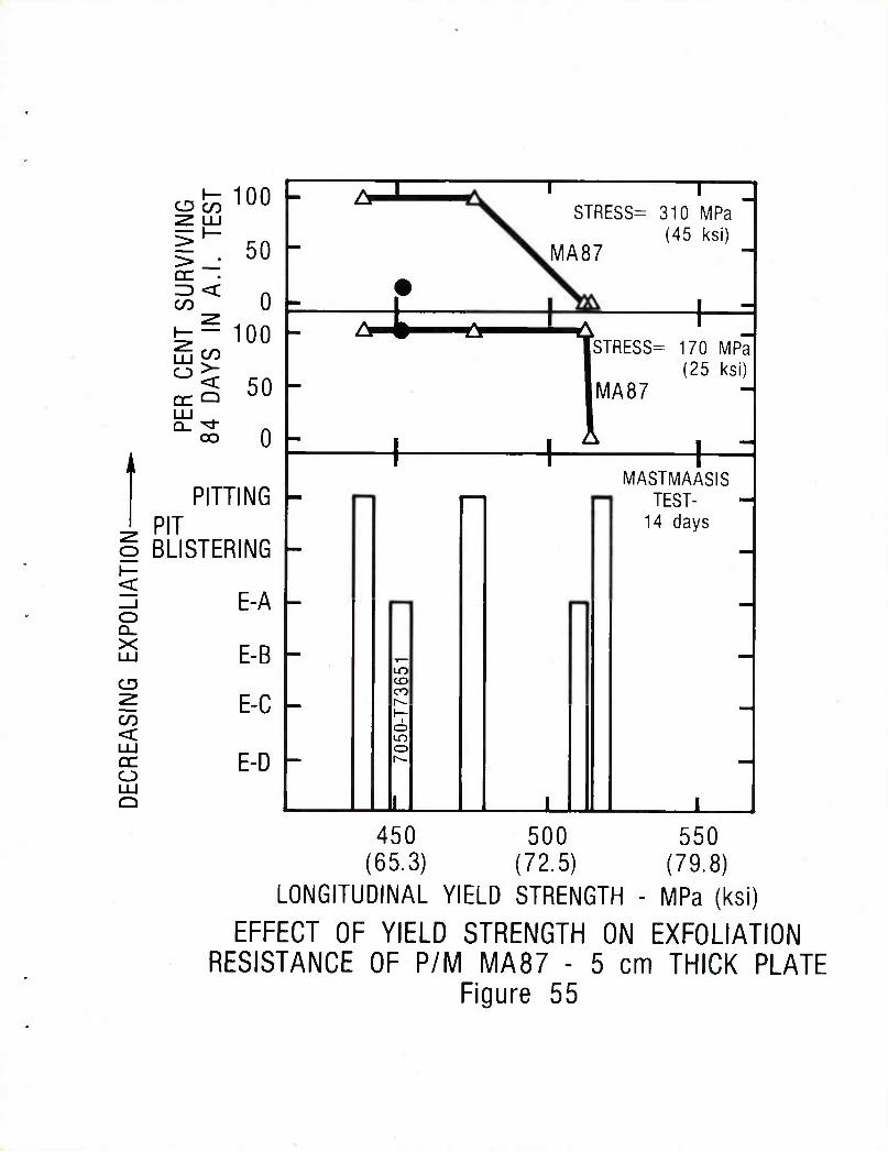
CD C/D 100
g . 50 <
CO 0 £- 100
0< 50 or <=> JU
oo
i
o
< _J o Q_ X LU
CD
< LU QC O
0
PITTING PIT BLISTERING
E-A
E-B
E-C
E-D
=t
1
STRESS=
MA87
1
310 MPa (45 ksl)
1STRESS=
MA87
170 MPa (25 ksi)
J.
MASTMAASIS TEST-
14 days
± 450 500 550
(65.3) (72.5) (79.8) LONGITUDINAL YIELD STRENGTH - MPa (ksi)
EFFECT OF YIELD STRENGTH ON EXFOLIATION RESISTANCE OF P/M MA87 - 5 cm THICK PLATE
Figure 55
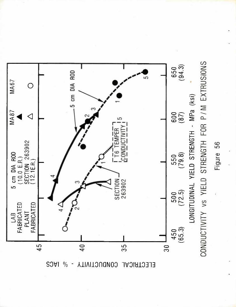
CD < o
oo < < <
CvJ CD <y>
o DC rr
CO CO
<r 111 ^ ^ O LJJ
LD o PT E o Ocg
LUT— o oo^^ LO
3 '< t= < —I oc 2J DC
DO 51 DQ < <
LO
CD CO
CO 05
CO
o CO
or ^ X co LU
CC Q-
CO CO
DC O
CD
QC CD r-> OO^ I—
LOS Q DC
CO LO
CD
=3 cn
^ Q
SK
< LLJ O lO Z >_ O cj Q
^ CO t >
o
^ CO ^>lO "^r co
LO CZ3 LO co
o co
O
Q
O O
SOVI % - AllAllOnQNOO 1V0iyi3313
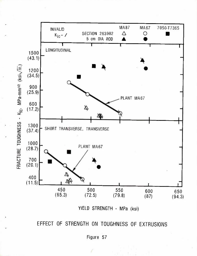
1500 (43.1)
14 1200 i (34.5)
| 900 E (25.9)
INVALID
Kjc-/
I LONGITUDINAL
SECTION 263902 5 cm DIA ROD 1
600 (17.2)
CO CO
ZD o
1300 (37.4)
1000 m (28.7) cc
o 700 g (20.1)
400 (11-5)
- SHORT TRANSVERSE, TRANSVERSE
PLANT MA67
450 (65.3)
500 (72.5)
MA87 A ▲
1
l\/IA67 o
7050-T7365
T
PLANT MA67
± ± 550
(79.8) 600 (87)
f
650 (94.3)
YIELD STRENGTH - MPa (ksi)
EFFECT OF STRENGTH ON TOUGHNESS OF EXTRUSIONS
Figure 57
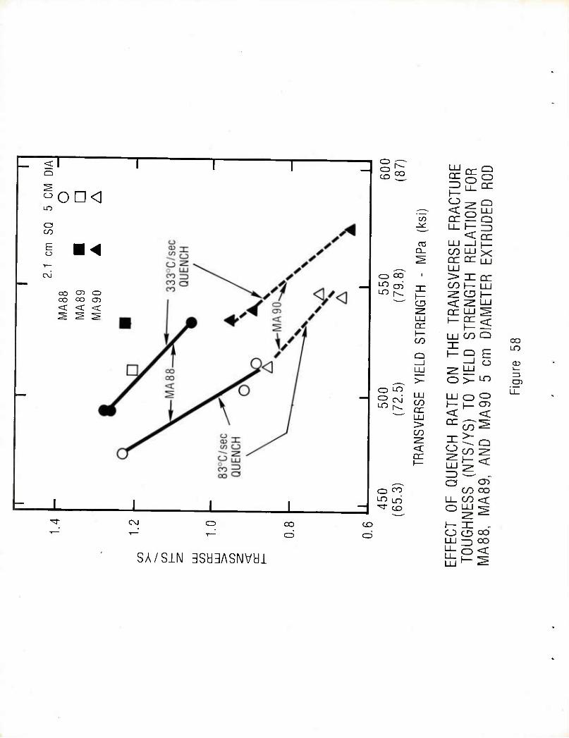
ITT
"on<i a CO
E o ■ ^
C^J
OO CT) O CX5 OO CD < < <
= I CM CO
cri
SA/SIN 3Sa3ASNVai
11
RAC
TUR
E IO
N FO
R DE
D RO
D
CO -^
< nr CV! II1 _J L_
Q_ CO UJ x ^ nr ac i2i
, _ LU CD OO 1 > mcr ^ cn T" CO 1— III
^ ■ J
i— ^ CD h- CD
LU TRA
TREN
A
ME
h— CO
Q
LU CO Q 1
h-Q E
CO
_J rH cj CD LJJ
>- ^ UJ 3
05 o LH^ i i
LU LU o ^ CO 1—1—05 cc LU > CO
<
h- U
ENC
H
RA
(NT
S/Y
S)
, A
ND
MA
, ^ a o^
o ro CO oo LO LT) LL co <:
- ^ CD O UJ ^ V . ^
CO 1— zc . C=3 o o oo
LU ^ OO ^o<

100
50
SECTION 263902 5 cm DIA ROD
MA87 A A
MA67 o •
PLANT 1 MA87 j
O 'A*' LAB \
MA87 \ \ LAB \MA67 -
h- CO LU h-
0
100
310 MPa (45 ksi) a
STRESS \ i i
- o o^ O AA • <
—T
>
o CO
CD
> > QC Z3 cn i—
50
0
100
241 MPa (35 ksi) STRESS
1 i
LAB MA67
l LU o DC LU Q_
- O (2^ O A£ —1
LAB 1 MA671
50
0
172 MPa (25 ksi) STRESS
I i |
450 (65.3)
500 (72.5)
550 (79.8)
SHORT TRANSVERSE/TRANSVERSE Y.S. - MPa (ksi)
EFFECT OF STRENGTH ON STRESS CORROSION PERFORMANCE OF P/M EXTRUSIONS
Figure 59
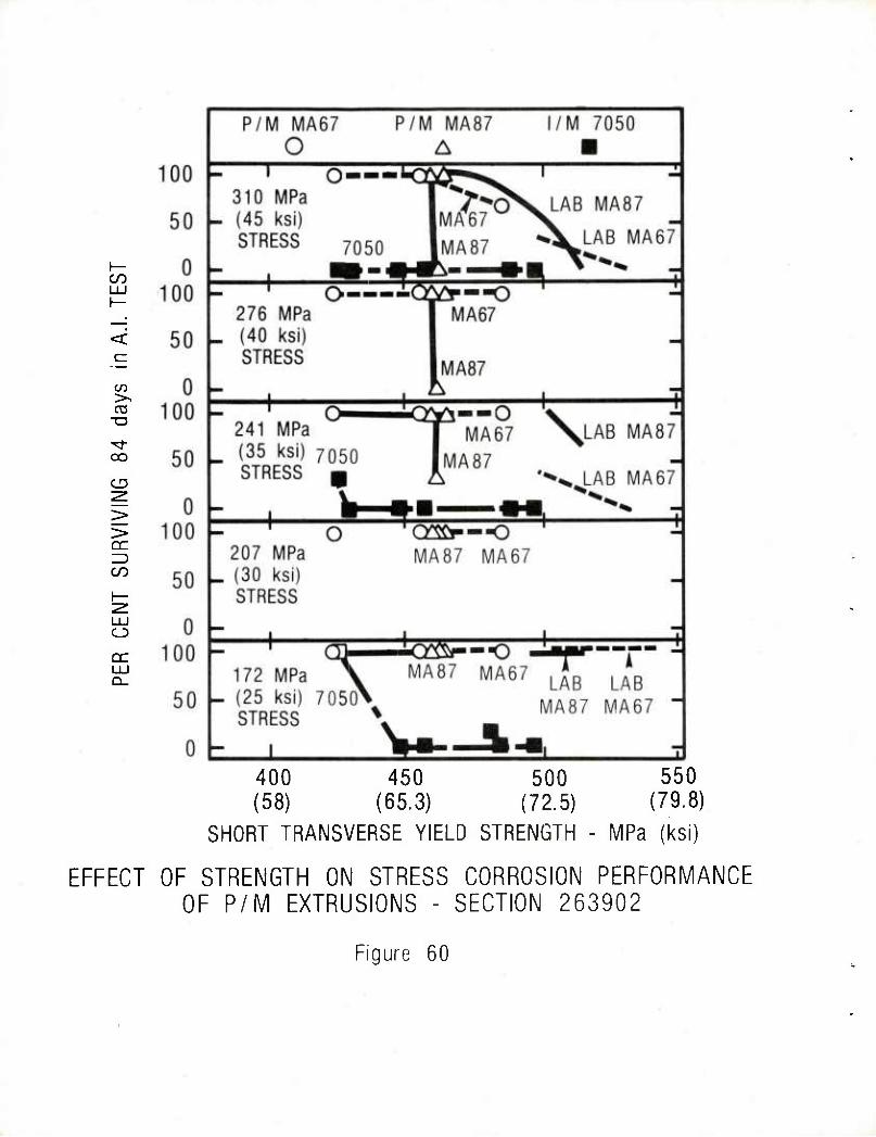
C/D
03 >^ CC
■o
oo
CC
CO
LU o CC LU
400 450 500 (58) (65.3) (72.5)
SHORT TRANSVERSE YIELD STRENGTH
550 (79.8)
MPa (ksi)
EFFECT OF STRENGTH ON STRESS CORROSION PERFORMANCE OF P/M EXTRUSIONS - SECTION 263902
Figure 60
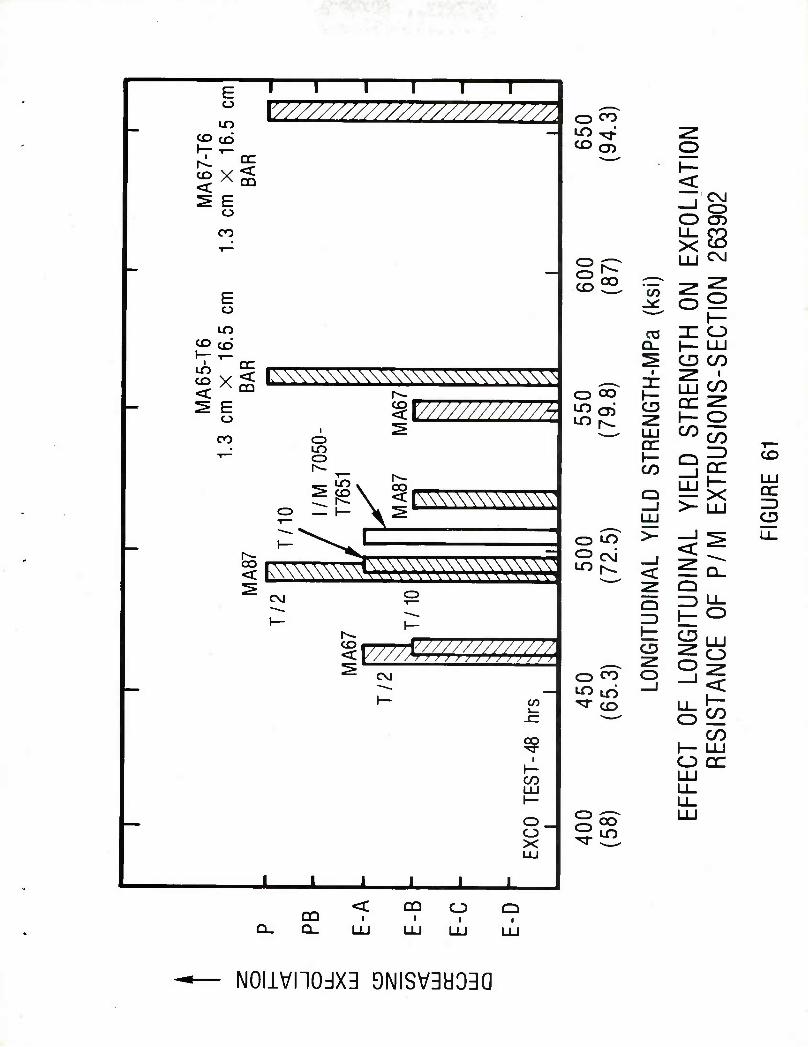
E o
1" I I 1 1 V/7 TT",
— LO CO cd
U/* ////////////////////. o CO
O r ' nc ■^ ^ ^^^
-x< 1— <
^ E o o
OsJ
CD CO Ll_
X ^
E o
LO CO co
ig "c/j
LU
o
1—
C\J
o 1— o LU
— MA
65-
7 1.
3 cm
X
1 BA
R
^ CO
i
1— CD
LU □C 1— D
STR
ENG
U
SIO
NS
-S
l\\\\\\\\\\\\\\\\\\\\\\\\\\N i^- ^V/////W///A
CD
— go <
t—
r^- ">\ te
CD LO O cJ
CO
_l LU >-
<
_i LU
_l <
DC h- X LU
LU or
^ ^ < IWVW^V^WVW - \~ CD
1 Ll_ ^
C\J <—> rS 3 LJ_
h- h^ 1— CD
O _l
^ O
— Q CO
"^ CD
CD
O 1
LL
LU O
< 1— CO
^ rrrrAW/;///;////// ± CVI
1— (/)" ^i —' O
^ 1— CO LU
co O DC LU
LU LL_ I— Li_
o_ o X LU
1 L 1 1
11 LU
QQ Q_
CQ i ■
N0llVn0dX3 9NISV3a33a
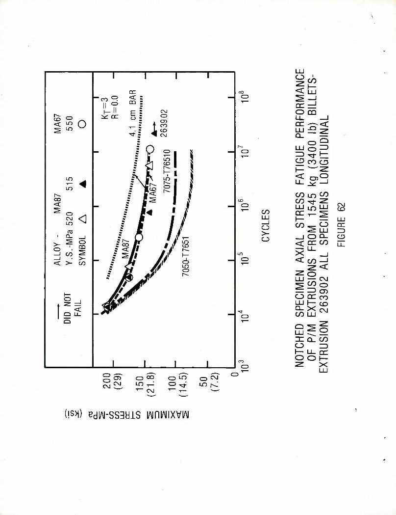
1 1 1 1 DC oo AN
CE
ETS-
-co ^ < = - O ^ —i II ° m =
1 S-1 1-11 c - CM O DQ
& 0 ,-, ^ DC g S O Ll_ _J is© T- : t co
• r ^ to , PE
R 0
lb)
DIN
A
5 L 551
/I1
r^ O LU o —'
CD CO ^rj
2^3 t^ CO in c^)
MAS
Pa 5
20
L
A
CD
o CO
co ^r 2 LU LO LU 0= T- ^
CO LU 1— — LU
' / //
-_J o >- o
co^- o ^ LU
_l O Q_
QC ID CD
LOY
S.-M
MBO
• Is- kr i LO
un
<- cr co Ll_
< ^ C/D O <co-J
2: *=< ^ o LU — C\J
^^ ^& l^g Mi Jv 1— Mf^w O QC CO J%jJr LU 1— co
-Ifr ■>3- ^ X C\J CO LU
Q
OTC
HED
OF
P/M
TR
USI
ON
I I l I CO
CD z x LU
g oT o^ o LO o^ ^ D 1~
^CVJ LO-T^ o^; LOr^ 1 CNJ T— i— '
(!s>i) BdlAI-SSdHlS lAiniAIIXVIAl
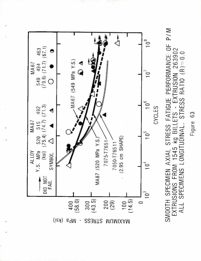
<
CO 1—
CD t< ^3" CD
^3- . CD T— ^3- r^-
CD ^D
O
oo <
C\J co
LO r^-
o ^r LO r^ ^vl
O Q_ co
CO
>-
o DO
>- CO
i <
<
oo CD
c\J
to CD T- CO
LO
CD
CZ3
CD
o o CZ3 ocj
CD ^"5 CD crj
CD LO
(!S>|) Bd|/\| - SS3H1S lAiniAIIXVIA!
O CvJ CD
LU CD O cr> "ZL CD <: CM
CD CD
DC
o o
X
^o
< QC
CO CO
CD
CO QC I— CO
CO _j
LU CQ
I- ^i
x f- <
^ o LU DC
CD
O I
CO
LU ^^ O Q_ g LU CO — Q_
CO CO
l-DC-j
o x <
CO
co CO
CD
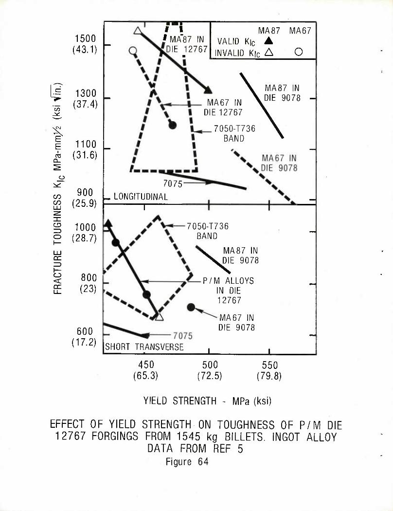
i CO
E E
Q_
CO CO
CD
o
o < DC
1500 (43.1)
1300 (37.4)
1100 (31.6)
900 (25.9)
1000 (28.7)
800 (23)
600 (17.2)
I I § MA87
HE 12767
MA87 MA67 VALID K|c ▲
INVALID K|c A O
MA67 IN DIE 12767
7050-T736 BAND
MA87 IN DIE 9078
7075 LONGITUDINAL
T
7050-T736 BAND
MA87 IN DIE 9078
P/M ALLOYS IN DIE 12767
MA67 IN DIE 9078
SHORT TRANSVERSE ± J. 450
(65.3) 500
(72.5) 550
(79.8)
YIELD STRENGTH - MPa (ksi)
EFFECT OF YIELD STRENGTH ON TOUGHNESS OF P/M DIE 12767 FORGINGS FROM 1545 kg BILLETS. INGOT ALLOY
DATA FROM REF 5 Figure 64
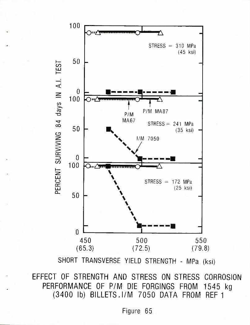
100
CO
CO
OS
oo
CD
>
CO
o QC
50 -
0 100
50 -
0 100
50 -
-
STRESS = 310 MPa
-
(45 ksi)
■ ^ m
P/M P/M MA87
-
MA67 STRESS = = 241 MPa V (35 ksi) -
X l/M 7050
V •m -■
\ -
\ STRESS = 172 MPa \ \ \ \ \ \ \
(25 ksi)
v - -■ 0
450 (65.3)
500 (72.5)
550 (79.8)
SHORT TRANSVERSE YIELD STRENGTH - MPa (ksi)
EFFECT OF STRENGTH AND STRESS ON STRESS CORROSION PERFORMANCE OF P/M DIE FORGINGS FROM 1545 kg
(3400 lb) BILLETS.I/M 7050 DATA FROM REF 1
Figure 65
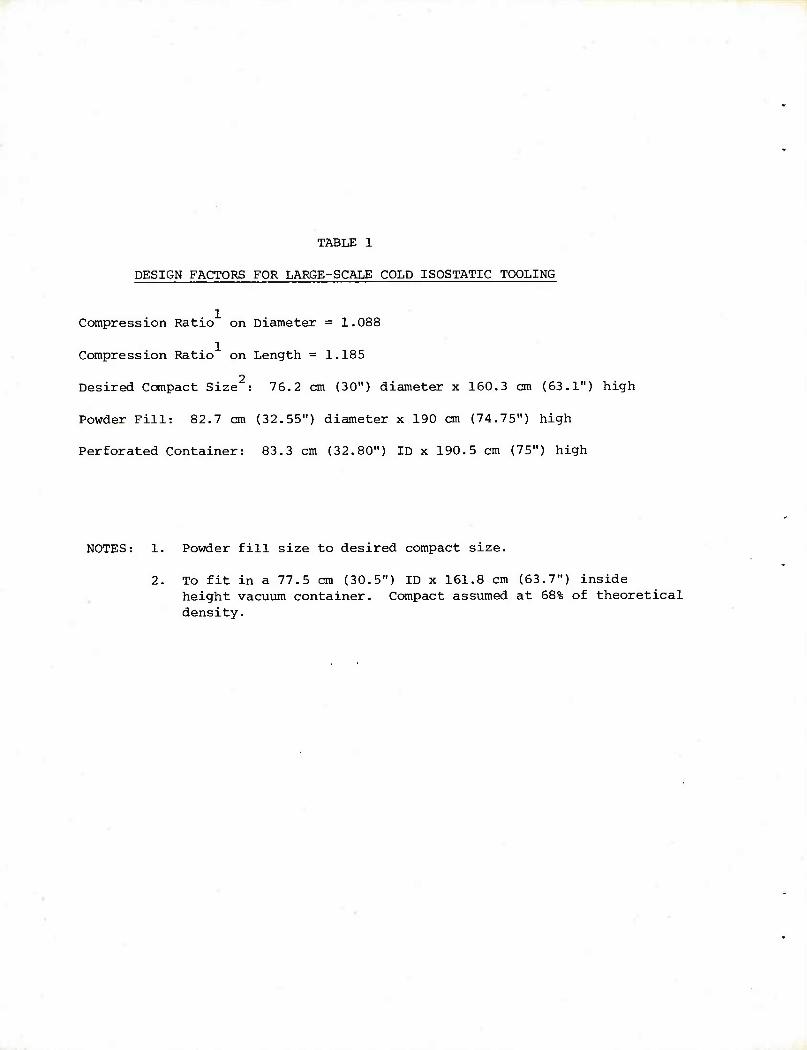
TABLE 1
DESIGN FACTORS FOR LARGE-SCALE COLD ISOSTATIC TOOLING
Compression Ratio on Diameter = 1.088
Compression Ratio on Length = 1.185
2 Desired Compact Size : 76.2 cm (30") diameter x 160.3 cm (63.1") high
Powder Fill: 82.7 cm (32.55") diameter x 190 cm (74.75") high
Perforated Container: 83.3 cm (32.80") ID x 190.5 cm (75") high
NOTES: 1. Powder fill size to desired compact size.
2. To fit in a 77.5 cm (30.5") ID x 161.8 cm (63.7") inside height vacuum container. Compact assumed at 68% of theoretical density.
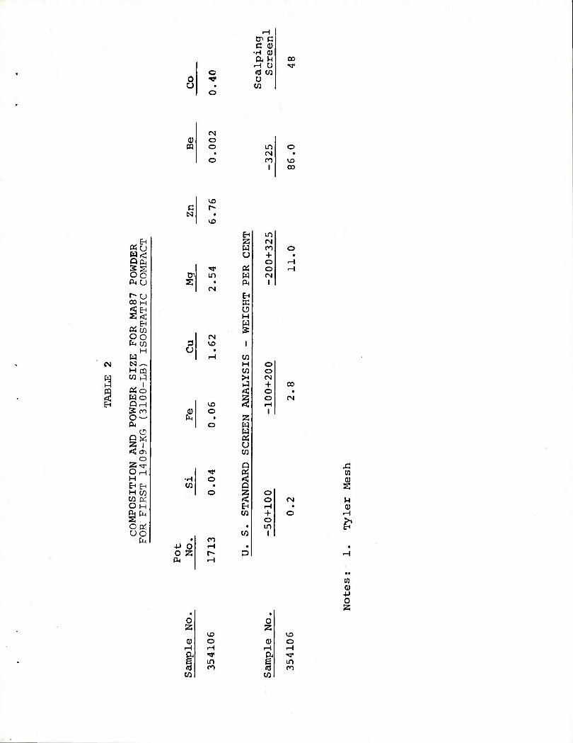
c
H 1 Cn C c (1)
•H 0) a ^ M o a CO o
CO
00
O O in
<N
I 00
EH «u H< QS gs oo a< u
r-u CO H
2<; EH
PSw oo fe M
H H N^^ H pq w 9 OH O Wo QiH IS ro O — &<
u D« S | < cn
o 2^r OnH H MEH H CO W pj OH gj fe oc^ oo
CM
c
Cn S
ix)
in
(N
<X> o
•H CO
O
-P 0 0 2
EH Z w u
w c^
EH K O H W
CO H CO >H
<
w
o CO
Q
< En CO
CO
in CN M + o o CM
I
o o (N + o o
o o rH + o m
i
CO
CN
(N
i (U
o
0) rH a
vo o rH
in n
0
rH a
CO
tn Hi
■p
o
in
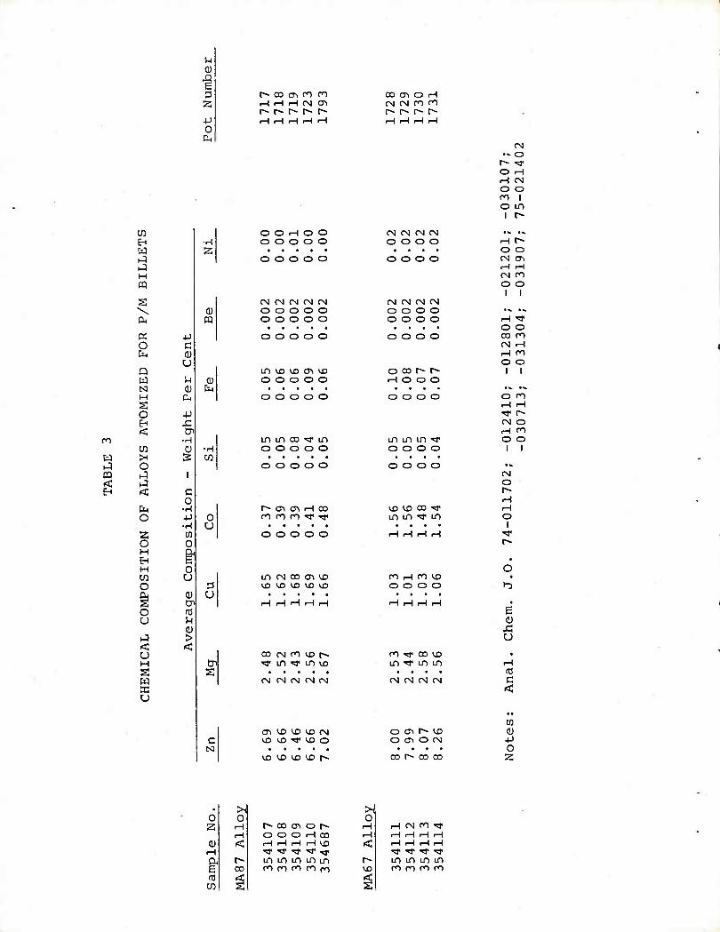
rn
W
m <
w EH W
H CQ
ex O fa
Q W N H s o <
cn
o
<
o 2 O
w o
s u H s w « u
u 0)
-Q E 3
4J 0
4-1
c U
M 0)
+J
en •H
CD s
•H 2
0) PQ
c o
■H -P •H
CD 0
| o u cu tr
0) >
s
r~ co (Ti ro n oo cr\ o rH rH rH rH CN CTl CM CM cn n r^- r~- r~ r- r~ r-~ r~ r- r- , r-l rH rH rH rH rH rH rH rH
-030107;
75-021402
O O rH O O CM CM CM (M •« ■« O O O O O o o o o rH r«
• • • • o o O O O O O o o o o
-0212
-0319
CN (N CM fS CM CM CM CM CM • i
O O O O O o o o o ... ii.
O O O O O o o o o rH >W • • • • • • • • • o o o o o o o o o o o
0128
0313
in VD VO CT\ VD o oo r- r^- i i o o o o o rH O O O
• • • • • «N •»
o o o o o O O O O
12410
30713
in m oo ^ in in m in «* o o o o o o o o o o o I I
o o o o o o o o o IN o
rH t- <n a> rH oo ix) vn oo ^ rH cn n m >!i< TT in in ^r in O
■ • « ■ 1 o o o o o H H rH rH
• O
in CM oo cn vo n rH cn 1^5 • VD VD VO ^O VD o o o o
• • • • b
rH rH rH rH rH rH rH rH H • e 0) si u
00 (M n VD r~ cn ^r oo vo . rr in ^s" in vo in ^T in in rH
• • • • CC CM CM CM CM CM CM CM CN rg c
cn CTi VC y3 X) CM O <T\ r^ U3 0) VD VD TJ< ^X) O O (Ti O CM -P
• • • ■ 0 U3 IX) U3 U3 [^ 00 t^* 00 00 2
. H 0 0 z rH
rH 0)
, 1 <:
a r- b 00 to
^
r- oo cn o p« O O O rH 00 rH rH rH rH VO ^ ^ ^ ^r ^< m in in m m n m m m cn
0
r-
rH CN n ^r
^ ^ ^3* ^
m in in in cn m co m
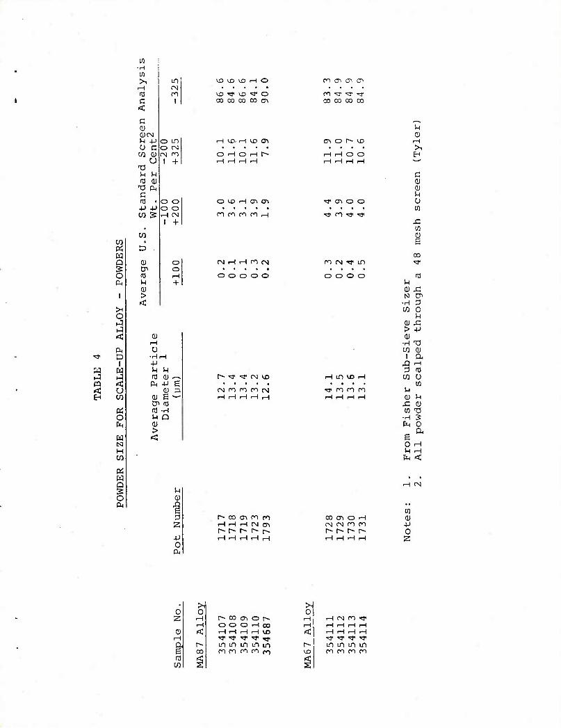
EH
K w Q s o
>H
o
<
D I
w
u CO
o
tq
H
w Q EC O
>1 H 10 c
<c c 0CN)
u CO
M tO
c ro . +J -P CO 5
CO
d
to M 0) >
LT)
rsi ro
I
o LTI O CN CN n
I +
o o o o rH CM
1 +
o o
0)
0 •rH,H ■p
IH M 03 CD ^-^ o, +J B
0) 3 (U s ^^ Cn 03 03 •H u P (1) > <
1-1
I -P 0 Hi
1^3 1^3 VI3 f—( O
UD "=*• ^3 T1 O CO OD 00 CO (Ti
rH >X1 r—I U3 CTl
O rH O iH r~
O CD iH CT> (T\
ro n m ro rH
CN rH r-H n f\l
o o o o o
ro ^ 0s. O
r^ ^r ■rr tN CD
rsi m ro n cs t-f .-H r-H i-H rH
m ^ -y ^r CO 00 00 00
M 0
CTI o r~- UD rH • >,
t-H i-H O O B i-H rH rH iH
c o
^ O-i O O u . • • M
•g< n ^< •rji J3 in
00 n CN •fl" in «*
■ t • • o o o o
SH (0
0) £! N CT
•H 3 CO 0
u 0) 4^ > -P 0)
■H T3 ' CO
1 0
X! rH
3 03 iH LD CD rH CO 0
# • ■ • CO ^T ro ro ro H rH H rH rH a u
x: Q) M nd
•rH ? fe 0
e o rH
iH rH
fe <
r- oo cri d ro rH rH rH CN CT> r>-1^ r- r- t-^
CN
cn 00 C^ O r-H tu CN CM n ro p r- r» r^ r» 0 rH rH rH rH 2
. H 0 0 2 rH
rH
. | < a, r» b 00
^
r^ c» CTN o r*- O O O rH CD rH rH rH rH CD ^T ^ ^ ^J1 ^y in cn cn LO m m rn m m (<)
>1 0
1—1 rH CM ro >* rH rH rH rH rH
< rH rH rH rH rf ^r ^r rr
r- in LD in LO <D CO n n rn
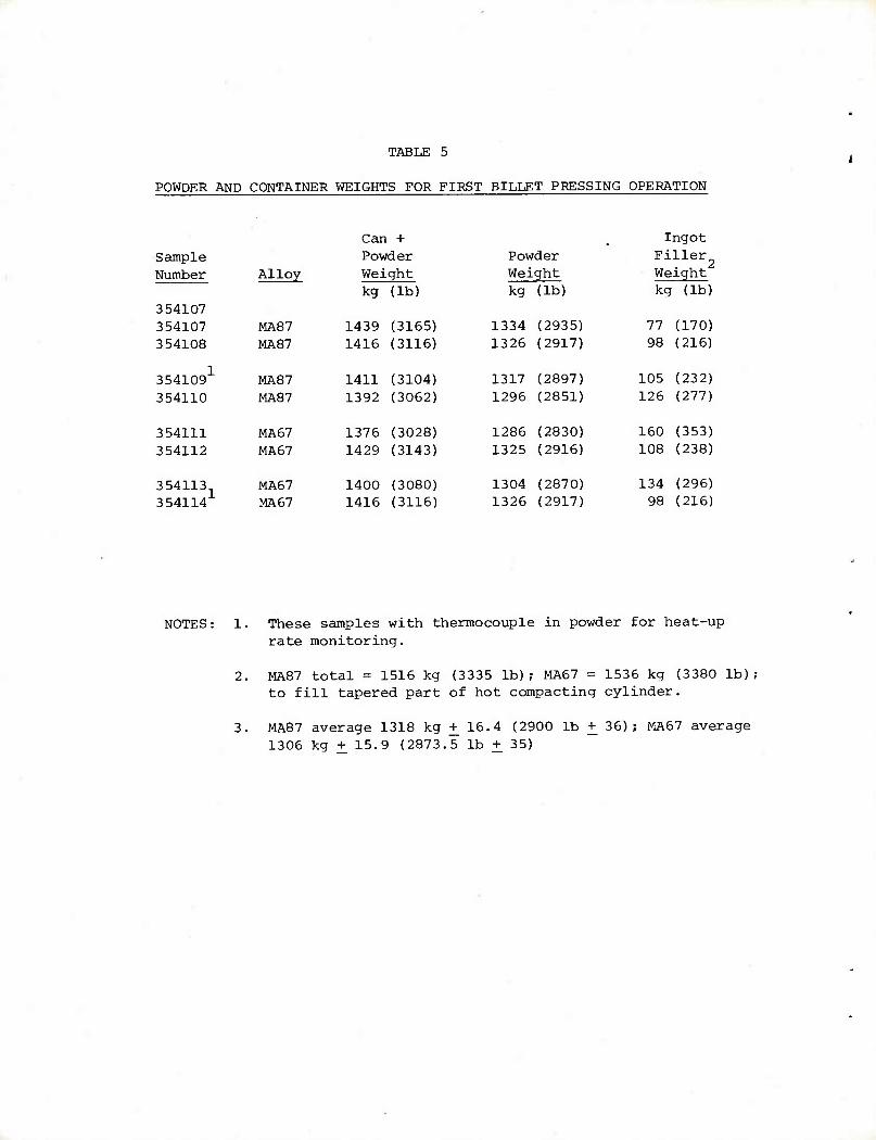
TABLE 5
POWDER AND CONTAINER WEIGHTS FOR FIRST BILLET PRESSING OPERATION
■
Can i + Ingot
Sample Powder Powder Fi Her Number Alloy Weight Wei .ght Weight
kg (lb) kg (lb) kc f (lb) 354107 354107 MAS 7 1439 (3165) 1334 (2935) 77 (170)
354108 MA87 1416 (3116) 1326 (2917) 98 (216)
3541091 MAS 7 1411 (3104) 1317 (2897) 105 (232)
354110 MA87 1392 (3062) 1296 (2851) 126 (277)
354111 MA67 1376 (3028) 1286 (2830) 160 (353)
354112 MA67 1429 (3143) 1325 (2916) 108 (238)
354113 354114
MA67 1400 (3080) 1304 (2870) 134 (296)
MA67 1416 (3116) 1326 (2917) 98 (216)
NOTES: 1. These samples with thermocouple in powder for heat-up rate monitoring.
2. MA87 total = 1516 kg (3335 lb); MA67 = 1536 kg (3380 lb); to fill tapered part of hot compacting cylinder.
3. MA87 average 1318 kg + 16.4 (2900 lb + 36); MA67 average 1306 kg + 15.9 (2873.5 lb + 35)
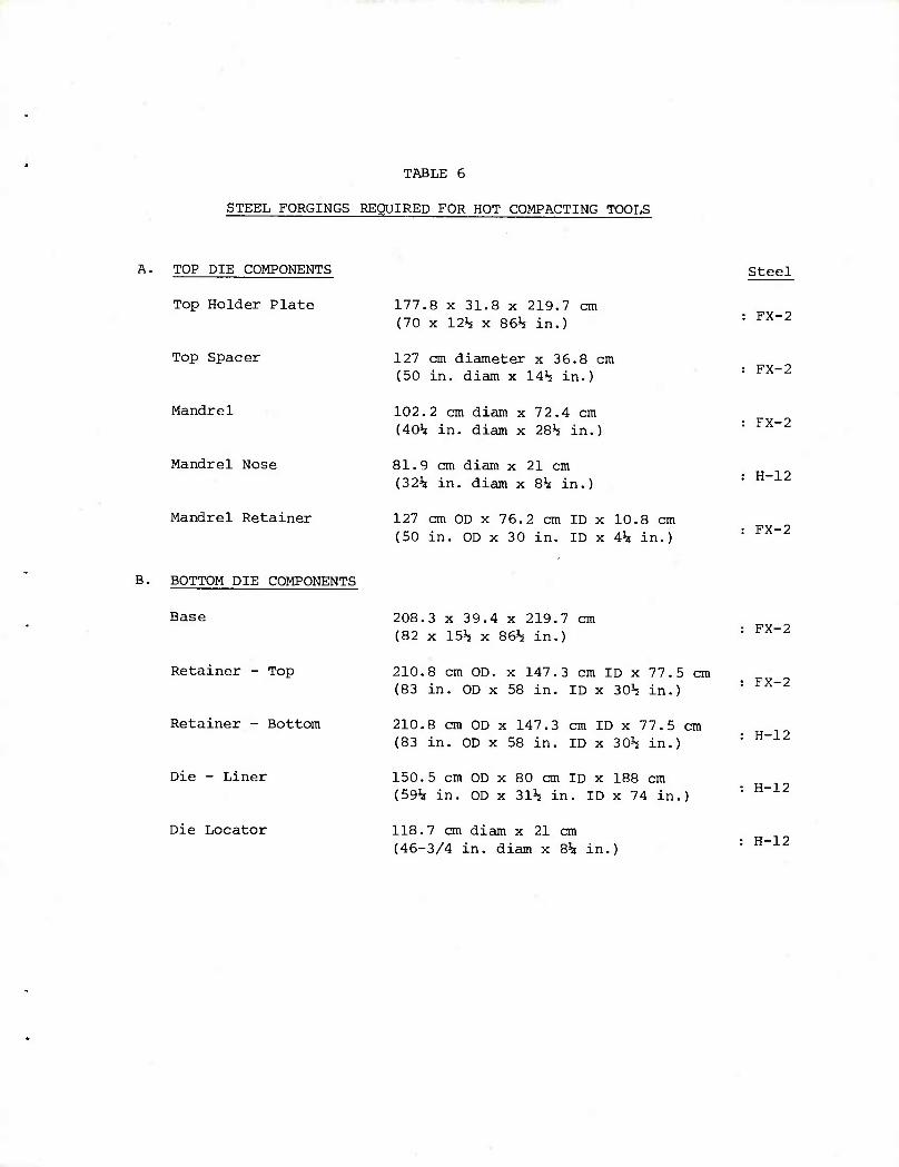
TABLE 6
STEEL FORCINGS REQUIRED FOR HOT COMPACTING TOOLS
A. TOP DIE COMPONENTS
Top Holder Plate
Top Spacer
Mandrel
Mandrel Nose
Mandrel Retainer
177.8 x 31.8 x 219.7 cm (70 x 12% x 86h in.)
127 cm diameter x 36.8 cm (50 in. diam x 14% in.)
102.2 cm diam x 7 2.4 cm (405» in. diam x 28^ in.)
81.9 cm diam x 21 cm (32^ in. diam x 8h in.)
127 cm OD x 76.2 cm ID x 10.8 cm (50 in. OD x 30 in. ID x 4k in.)
Steel
FX-2
FX-2
FX-2
H-12
FX-2
B. BOTTOM DIE COMPONENTS
Base
Retainer - Top
Retainer - Bottom
Die - Liner
Die Locator
208.3 x 39.4 x 219.7 cm (82 x 15h x 86^ in.)
210.8 cm OD. x 147.3 cm ID x 77.5 cm (83 in. OD x 58 in. ID x 30*5 in.)
210.8 cm OD x 147.3 cm ID x 77.5 cm (83 in. OD x 58 in. ID x 30^ in.)
150.5 cm OD x 80 cm ID x 188 cm (59^ in. OD x 3115 in. ID x 74 in.)
118.7 cm diam x 21 cm (46-3/4 in. diam x Bh in.)
FX-2
FX-2
H-12
H-12
H-12
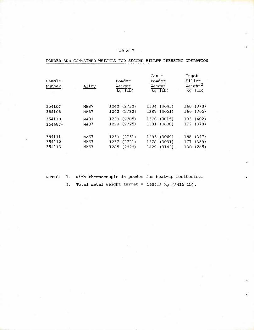
TABLE 7
POWDER AND CONTAINER WEIGHTS FOR SECOND BILLET PRESSING OPERATION
Can + Ingot Sample Powder Powder Filler Number Alloy Weight Weight Wei ght^
kc I (lb) kg (lb) kg (lb)
354107 MAS 7 1242 (2732) 1384 (3045) 168 (370) 354108 MAS 7 1242 (2732) 1387 (3051) 166 (365)
354110 MAS 7 1230 (2705) 1370 (3015) 183 (402) 3546871 MAS 7 1239 (2725) 1381 (3038) 172 (378)
354111 MA67 1250 (2751) 1395 (3069) 158 (347) 354112 MA67 1237 (2721) 1378 (3031) 177 (389) 354113 MA67 1285 (2828) 1429 (3143) 130 (285)
NOTES: 1. With thermocouple in powder for heat-up monitoring.
2. Total metal weight target = 1552.3 kg (3415 lb).
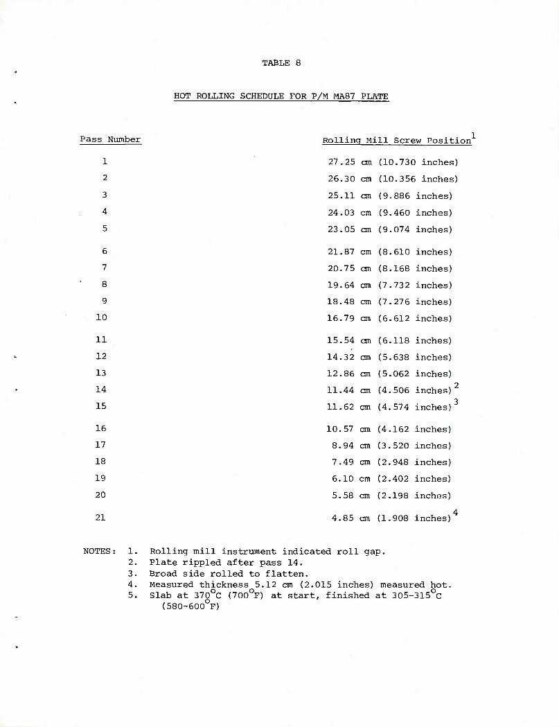
TABLE 8
HOT ROLLING SCHEDULE FOR P/M MA87 PLATE
Pass Number
1
2
3
4
5
6
7
8
9
10
11
12
13
14
15
16
17
18
19
20
21
Rolling Mill Screw Position
27.25 cm
26.30 cm
25.11 cm
24.03 cm
23.05 cm
21.87 cm
20.75 cm
19.64 cm
18.48 cm
16.79 cm
15.54 on
14.32 cm
12.86 cm
11.44 cm
11.62 cm
10.57 cm
8.94 cm
7.49 cm
6.10 cm
5. 58 cm
4.85 cm
10.730 inches)
10.356 inches)
9.886 inches)
9.460 inches)
9.074 inches)
8.610 inches)
8.168 inches)
7.73 2 inches)
7.276 inches)
6.612 inches)
6.118 inches)
5.638 inches)
5.062 inches) 2
4.506 inches) 3
4.574 inches)
4.162 inches)
3.520 inches)
2.948 inches)
2.402 inches)
2.198 inches)
4 1.908 inches)
NOTES: 1. Rolling mill instrument indicated roll gap. 2. Plate rippled after pass 14. 3. Broad side rolled to flatten. 4. Measured thickness 5.12 cm (2.015 inches) measured hot. 5. Slab at 370OC (700OF) at start, finished at 305-315OC
(580-600OF)
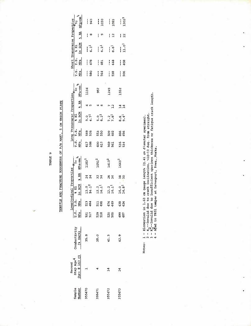
0) ■iH ■1J* U 0) a o
■ a-
en is • ft i o I CO I in
1 o 1 n 1 IN 1 ro 1 Cl 1 o 1 o 1 o l n
I CM I I CD
I CO I in
I CD I o I in
W n rt H 0) 2 a & ■^ in ^ ID [- CN «* ^
0 # rH rH rH n u
B 0) ng r-< ,_, M ,H 09 W CO O [^ O OJ tN CO CO ^f
* c ui *j in \D p- [^ 00 0^ > •H
g Si c IS m n ■ B co id ai ^D m o (^ CN KD \D - ■ ft VD tN in m O Ol ^ in
r- 1 >< s in in m in m ^ V <*
CO ID [^ CO O CN <T\ rH ^0 *$
§ H S H cr> O H \0 & m m \D in \£> \£) in in in m
EL, en o
s CO Jf CO OJ C-i OJ M
9 w u 1 m H m m H 1 CO in rH ■*
H s 4 id rH o ■^ s a in
H iH rH rH
2 9 -H
§ 5 g ^t ^ CN ■■* <£) -^ 00 o 0) CN CN cn ro CN PO m m
| & CtP
C g P< s CM r-i ,-4 r—(
H U O H (N rH CN H O CO h H W W a ro ^ CN Tf CN ^ "* ^ D c *> C H rH rH rH rH rH H rH
§ ■H
1 •H
a •H W S) ro ^f H rH t* (T> oo -^r H B >:§ H CO H <yi r- rj" CO CN CO c m ^< in ^ ^ ^ rf ^ a 0 1 ij ,
w td H [^ ay co o o oi r- • 0^ m H CN rH CN O 0^ CO
E-< S in in in in in m ^ <*
■H ~ > CO
■H O CT1 ■y < 0 H in 1 m it o u
o
CO
^^ 1 1
ID o~> Tl Bl li) C « H o I) a 6> II) in
CO -M in CO S
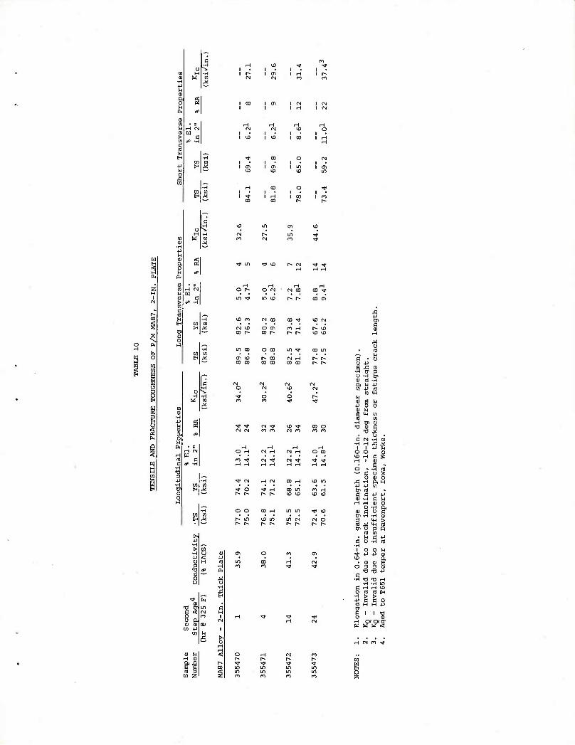
1 • 1 OT
1 • I • i in 1 Ol
ID & tD m
I
o S.
i
I? H > +J O
c o u
I o o a, 1) 01
O 1^ O CN <N CO co ^ in -«# m & h» r- CO <7>
CO l~ o oi CO p.
m p> CO CO
U1 CO O CO ifl ^r co in 1^ VD CO CO
r- co CO 00
CN CO CO
CM CN CN 'J CO •<)•
CN m 00 O cn m
r-i O rH
rH CN H CN H
H O CO
m ^j- CN rr CN ^f ■* <*
. I
O 10 -H ft U -P 0} 4-) OJ
cn m
•H cr 0) ■o oi c
-O ^ o •
C CN 'H CO ■H r-l .C ,*
i i iJ n O O 0 CD H C S i-i i a
o « — c
o ■p -p cy id c c 0) -rH
a) c u Di -H -H S >4-l CO ^ CM Dl O 3
(0 0) • u c
■a co o S 0) o a H cn
u a,
■a m a
•rH TI -a •H -H
co co > > c c ■p
s C I I "0 O 01 H QC CXCn W « S4 <
rH CN Cn ^
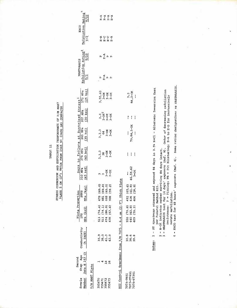
o 0
< < < < i i i i
W M W W
m o u < i i i i
w w w w
n. I 0. p,
H
M K5
r- co
gg u a < s S
Ot s fa u o
y 5 2 ES O S o W TT
O m
W o S s<; a in o <* H m U H < H E H O o g S fc ><; W •«;
u Q H
3 E-i
2 *^ O s H (N W »-' o 35 o U in
Sg S3
^^^ m •H a rn 3S rV
tN LD r* rsi rH
,M*
ni ^^ -H
M H ^r LD CN n
"-•
^ m •H
m s ^ in o r» »» CN
>■
Q ft 01
o in
m ^
vD ^ M ^ ^ O O O
u^ I I I in m ro m
CO
m w w ^ - o o o mill
CN ro n
O O
* co o O m ro I I
O O
m m
^ CO O CN
CO rH CO CO r^ co -^ o ^ ^ ^ ^
•^ H CO ^0
n rH ^ co H H [^ n in in ^y ^
(Tt o m oi
ft « OD en
M in rH OD U 10 ID in
■H £ S fN lO lO
in CN o «^ ^f ^T ■*
m CM 00 CO m
CTi en en 8 t^ ID m w
■** ** "• o o CTi
in * O UD in ^f w
U H in in -P in *£ m a \D r-- r^
O ■—i CM m 0 En En En f" r* r^ h* u 1 1 1 ^r « ^J- •^r in m in in in m m y t-- r- P- in un m m o o o o m m m m U3 > r- h-
ro O • I
fl CN
CD
o
CN
CXI - « I in o I in i
" m ID
O ID at m rn m
0 ■H en m •rl rH C 0) 0 -H U MH 01 0) X CO 01
CO
H tjc U e c
01
C OJ •H -H 0 JJ 01 ■H nj CO U P c 01 0 c0 ^ U M-C C 0) u &
■p 01 p ■H rH TJ 1 01 <
1 in O O
+J
CD
■O
nH U C U 01 < •H m -a i P
ISS O
CO
o\o LO 5
• c 01
m +J ^ -H u 05 tl 01
d (0 01 •H
c • 4-1
UJ 01 U) •H 01 -H >~ K rH ^c m 01 >" m Ti >,
CO 01 JJ IP ■^• ■a U -H 0) CO 3 ft a
■^ 01
■g CO 8 " 0)
LO & x « u 0 c 01 ft a a ■H 01 X > 0 CD -H 01 (Ji a > >i c X
ca rn u CO -H OJ C CN 3 •a -p ci3 CX) Eg 4J
^r -H in
■s? 0) rH ft c
0 P 3
01 J3 U II -H 0 01 JJ 0 p £ OJ 01 ■H ft c0 M E c H 00 +J ■p H ^r 01 >H 01 01 •• O
nj 0) 01 01 ip p 01 u -p ■P 0 a 0 a cu CO c cp
|| u m co H -P cu P
•H fn -O W 01 u en 0 9 rf -H 01 01 CD tj •rH rf 01 > 4J BU 0) E 01 s oi a x 01 O
o 01 0 EH Ifl
1 SB
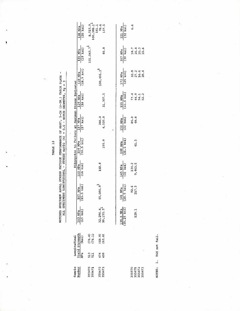
w H
a n 01
II » u tH H £ 1 E-
>H a
2 H M
1 o CN M •^ O
a 1 u
1 5H
in 2
Ol r-l i-H ^D lit
in CO H CO r- H CO ^D r- ro LD m rH H
in o «» o o
<S) o 00 CM CM m
o en
vo in co in <N H
CM co m en
^^ r- ^ m U3 -H .... m co ^D o o
C^ (N U3 ^T
^ O^ ^H CN
n) ■H . . a. tn in co X J2 co ■*
■r^ 10 C1 ffl (0 a, X CN f- s C0 H
^H 5 a tn c C
-H a) ■a n 3 -P
+J en ■H Cn Tl C H
3 (11 ■rH X
— t r-l ■H id
I Q
« ■^ ^ ^r in IT) in m ir> in in in ro m n m
O i-H (N m r^- r- r» r- ■^Jt ^ -^ -^ I in in in m m in in m ro ro ro ro S
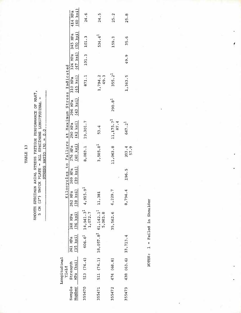
«
<*
Hi -H ft w \D LO CM CD S *! • ,
•^ ^r in ID ^t o CM CM <N CN rH «3
^-^ a •H ft 01 s ^ in O ^f in n ^
n3 -H ft 10
n3 •H ft M S M ^D m (Ti *f
^_^ a ■iH
ft in s ^ to o r- ^f CM ^-'
ITS -H ft in S 5 (Ti CT1
^_^ (0 •H ft to s M CN CO l£> ro CN
^_^ ca ■H ft CO s X
CO 'JD ^r ro CM *-'
^^ rd ■H ft m S M rH in ^r ro CM ^^
ro
H o
ro
H o
co
o ro
ro CO o
in rH
CN ro
ro in
in CO in
CO ro
c^ in
■^ en in a-\ •& in r~- ro
ro CO O
0^ CM CM
CC
CD
in ro
01
ro CD
CO • O
<M
r-- >* ^-i
en r^ . t» CO r- <-\ ■* •- CD
■* CTi
ro r~ o m CN
m
CD
H
en
r-t CN CM ro CM ^ r- ^J- CO CD cn o rH o in ». *. >. «. i*
^ rH rH in in rH CD
rH 00
ro
^r "cD r-
• ro
\D m t-i O o r- CD
CO rH
n CO
J3 CO
c ■rH
•H cti ft
rH CTJ ^-^ c £ -H
■H -P tn •0 -c & AS a rH c —■ -p o; (U •H •H in nJ Oi >< -P ft c w s 0 J
Q) u rH 0) a J3 £ g CU 3 W s
CO
^r ^f CO ro r-~ r- CD CD ' ^ ■^
ro rH <* 00 rH rH r» ro in in ^r ■sT
O rH CN ro h- f- f~ r- ^r ^r ■SJ1 <* in m in m in in in in ro ro CO m
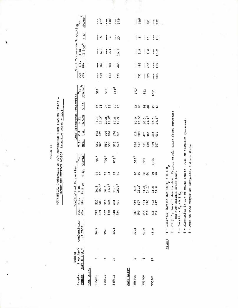
a) -p M g s o M rtP n.
(1) jr (0 E (1) > ^>
*> rH
m C I-J -H H ■P m m n b 0 >< Ss fl m
10
H s
i CN i in i o i ^o i m i u) i ^f IT t ^
i en i I 01
I Cl l in I in
* < Pi
W m
10 to ft E
CO
S
CN n (N ro n CN
in m CO o in in
H m o ^r PJ CM
r- o o o LO ^ m KD in m CN <N in m m in in m
ro y£> UD CO n ro (N (N CN m ro "^
0) U
J- j- J- -U o m in rH in ^H g O CN O ^ (N ^
CO CTi M O in in
ro ^p ^ M'
CO CN HO ^ r^ ro m uo in in in
> W •H U +J < O H
o u
^^ (1
01 Oi ro Ml 11)
-H 0 91 IB
(0 m u j= ^^
co ^o co rr ^ o CN **
in m in H m \D
o CM o ^■ H in
m in I-H ^ rH o CTi r^ in in ^ ^j1
CN CTi CN o o ^t
* ■a 0 M s O (0 o as ^ q
U1 rH ^D 0 rH (0 CO o cn T -H in 0^ o
rH o C
P H M ■H
x: , \0 ti P QJ ^) o 10 o 01 CO U-l -a Cn P
rH ro CN ^ CN ro d A
to
0 rH
o
c S H
p HI
ip M
j- d- tfl 3 a O CO O H 00 CD 0 0
4-1 10
p (Ti ro rH ^f rH ^r rd
rH i~\ rH rH rH 0) <D 0 Ol g 3 3 3 X o h
"B ■a 6 -H CO ID s
T? TI -P B Oi [^ *# o CV| r^ ■H ■H fO o rH s •^ CN C\ p* tfl ^ H rH <4H +J in in ^r -^r ^r ^ n) (0 A c > >
B J= ^ -H rH
LD -H -rl ■H C l£ I^ o ^r U) rH ^ J2 1 o H
CO 00 ^r CO CN rH ^ >1 ■H in in m m in in H rH ■0 ■a P 0 ■P +J c ■H id +J £ £ IS rH Ui tr tjl aj c 1i ■H -H > 0 rH rH c rH tn CO M H W <
0
0) u rH a)
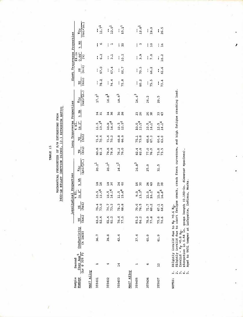
V M 01 a, o u ft
u 0
S « P X rH w •
S H
lu o 0 m
M tn iC iil r-j M H tji Bi ( ; W H UH H ( > r; K w h u
3 H 0 H 9 a; u
H
n n aa
o o
i
in
o . o a a) a) -
^ H ^r ^D O ^0 OJ n CN m ro (N
o H H
CN (N H
^D & ^D Cvj CO cn
H o O CO
\0
CO Csl CO CO (N o o CO
<-* CO
00 iO CO ^ ^ o CM ^'
in m in \£)
O CN o -^ M m
m \Q \D CO n m (N (N CN m n ^
o in m ^t in rH
o CN o rH
CN
^H CO ^) m ^ o
ro CO U3
\a o rH n
& o CN ^
a\ co CN m
o m O rH CO CO
H rH -^J- rH H
rH -^ H rH
\0 in r- CN H 0>
cr. tiO rH CO
o
a) o
3
m
'B C (3 aT n 3 C
■P nj > ■H ^i O 3 CJ u ft
01 ■p c n 0 <D n U
U-l <u M 1 0 ■H . al TJ tn U J^ 0 g 8
•rH S M 1 U o » 9 VO Hi ^ H C o o.3 (D — -a 3 c • c ^1 H w 9 nj C 0)
ti) tw (1) +J rH -P
O +J <a A H 0) >1
0 Di fl h^: 3 IH
W m
0 0 4J +J . • 4J
C (0 (1) <u 3 3 ^■H .
•a -a ■* 01 en ^0 ft •O Tl ■H -H o O (U ^H nH A •p m fl c > > U ■H H c c « LO
-H -rH 1
C ID 0 H
>i >i ■H H H Tl ■P 0 V -P ■H CO -P £ £ rH Bi Cn Bi til C 73
•rH -H > 0 (U rH H e rH Si Ul W H W <
rH CN n T in
w O
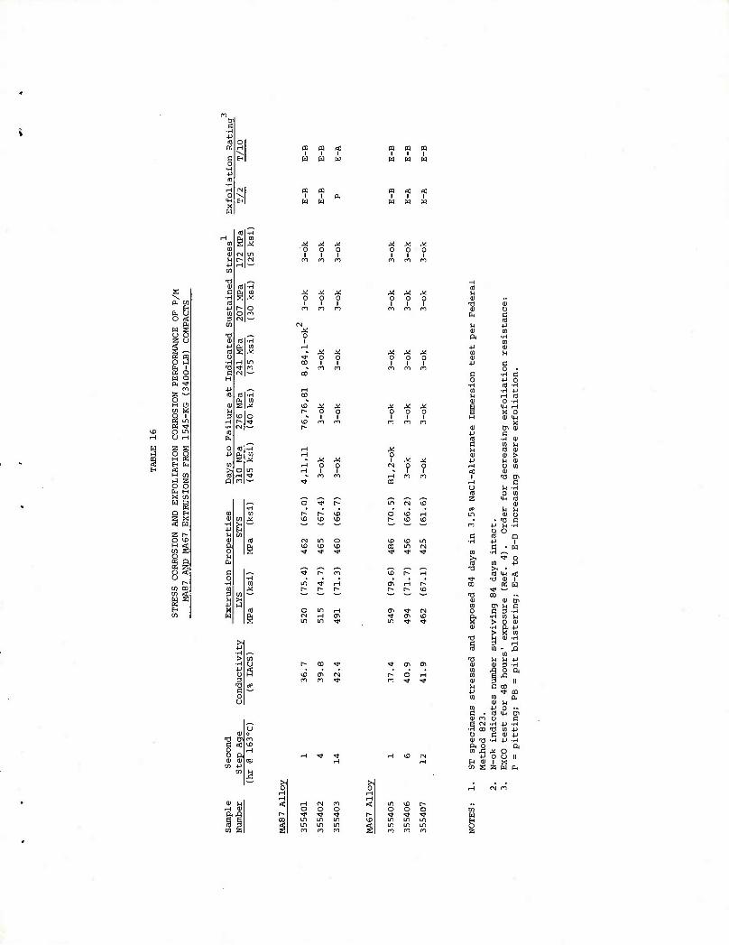
4J a
c 0
www
X w
HI WWW
tO H
s s 0. en
H t, U o rt
Q. m u
U g ,^
tg o ij
u i w o a ^
m z o H o m S o i
g o m u rH
2 2 o O H a H t. a: H 01 J z o o g H X ta W s Q E-i
I X W
z r> o VD M g o
o Q
u r^
09 CO CO 1 i B 01
0
3 en
O)
■0 0) to 4J ft 10 E o
•H H -a ^l* c CN H •P a) a) ft ID S >j 3 10
nH r* ■H fN (U W
0 (0 J-i ft
s to >, o a rH Q ro
-H
o 3 -a c o u
o
o
M o i
o o i i
0 o 1 I
X o I
tO *0 t£
0 o 1 I
(0 X ^ X kJ 0
1 0
1 ? 0) 13 0) n m m 0) h H
■p
u
n •H ■0
M M X in u 0 i
0 1
0 1
0) -P c
m ro tn B o
■H
01
M <D
■3 B *> 0 03 -H
•H +J ^H Ifl O -H
X X X m nH 0
1 0
1 0 i H
X 0 01 MH
n M m 01
10 c
X en 0) Cj
■rH 01 ro u « kl IB 01
0 0) 01 > i X « +J H 0)
CM 0 0 H o ro 1 i < 01
H ro ro 1 T3 tJi CO H
u fO
B O M
z a ro in CM *D (*> 01
o 10 <-i in 0) o f^ vC VD • . ■a s 1 ' "^^ ' n
o H -H o c 10 Q
vD kD IT) •H 4J 1 CO in CM c * w ^T ^r >•
>1 ■H
? 0 rO ro 4J
■O >, ID r^ ■-( ro !« <
T iO 01 1 ai H r^ CO a: w r^ l> U3 ^f ^^ ■a CD
0) en m Oi H C en ^r CM O 5 3 -H
^r en VD a ■H ro ^ m •» ^r X > O 01 0) t ft +J
X m •0 U 0) -H
§ 3 rH (0 - ja
01 « i-H U P « en en 0) 3 -H o a
f> o H ro ■C m «* ^r 0) ^J II M c 00
+J ■* (B ro ro 0) M* ro ■p O ~ c . ifl HH &
0) m 0 c i <N -rH ■P -H
■H CD T) 01 4J D c 01 4J 01 T3 ■H ■P -H Ol O ft ro £ ^ O
nH VC CN 4-1 O U II H
0J s 1 z
X W ft
§1
w I z
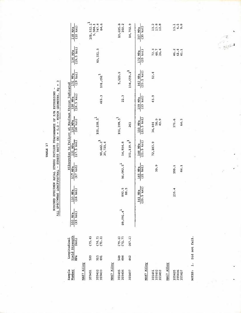
f-i t-i *& yQ
CM ^ r^ ^
co CN cyi
mo 01 CN CD CO
ro n CN
H in ao m VD CTi
0)
(0 u
0) H
& a
CN ^ rH
VD H nH ■J VO T
^T 00 O rj- in •rj'
0)
H •H c«
u
CN in CD M co r-
co o cr\ CN
-H 01
cX>
O
A nH p M rr C B
■H CD Tl U 1 4-1 il cn ■H
Cn "0 n nH
^ cu -H >H
o o m m m m ro m
^ 01 M3 in ^ ^r
>1 0
< in 10 ?* O o o
r^ ■^ ^r ^r U3 m m m
m m in s ro n f)
m m m m m in m m m
H in ^D r^ o o o
■-• ■^r ^r ^ o m in m
in in in SI n m n
3 C4-I
3 a
o
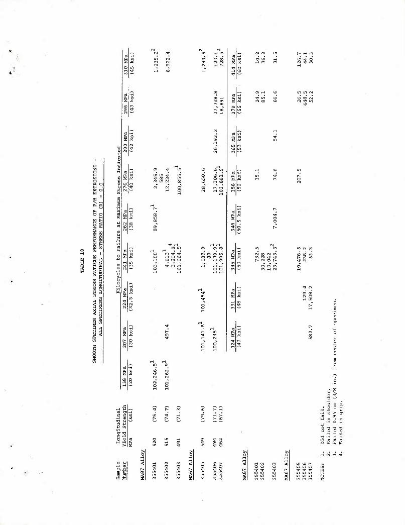
■v
-p ro
1 o ■rH
w ■c 2 c O H H tn cn a m ffj o <u H ■ H x o JJ H w
rnfi 10 & c c
•H a) T) H :3 -p
■u CQ ■H 01 Tl C rH
Q 0)
Lfl LT) rf •q- CO CN m in CN
o oo ro co
ro ^ ^ H O ^ CTi (N O
• n3 co CTI cn in PM CO 00 rn (Ti S O H (Ti
in 1
O 1£ rH
o o
Lfl m m CN n
fN co (N in CO CO ro ro (N ^ ^ r~- ro in r- CN o r- •=1* CN
O O ro O m iH CN H
cn CD CN O H in « c
r- rH g
■H 0 a) ft
g u B o ft
• CO M \ OJ ro
T) ^ nH sea • 5 0 -H
UD P^ rH -H w m tn
ai rH r^ R] <T> h- p- & 4H C . fl
d not
iled i
iled 0
iled i
cn Tf CN •H nj nj nj ^r cn ID Q fe fc CM m -* ^
0 rH
rH CN rO -^
in ixi r- < rH CN ro < in \D P- o o o O O O o o O w ^r ^T ■<* P^ ^ * ^r r*» ^ -^ ■* in m in CO m m m KD m m m in m in m m Lfl in m in ro ro ro s ro ro CO § ro ro m s
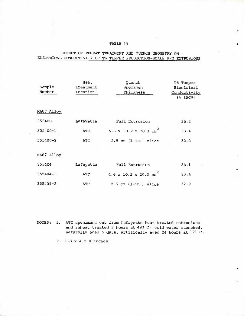
TABLE 19
EFFECT OF REHEAT TREATMENT AND QUENCH GEOMETRY ON ELECTRICAL CONDUCTIVITY OF T6 TEMPER PRODUCTION-SCALE P/M EXTRUSIONS
Sample Number
Heat Treatment Locationl
Quench Specimen Thickness
T6 Temper Electrical Conductivity
(% IACS)
MA87 Alloy
355400 Lafayette
355400-1 ATC
355400-2 ATC
MA67 Alloy
355404 Lafayette
355404-1 ATC
355404-2 ATC
Full Extrusion
2 4.6 x 10.2 x 20.3 cm
2.5 cm (1-in.) slice
Full Extrusion
2 4.6 x 10.2 x 20.3 cm
2.5 cm (1-in.) slice
36.2
33.4
32.8
36.1
33.4
32.9
NOTES: 1. ATC specimens cut from Lafayette heat treated extrusions and reheat treated 2 hours at 493 C, cold water quenched, naturally aged 5 days, artifically aged 24 hours at 121 C.
2. 1.8x4x8 inches.
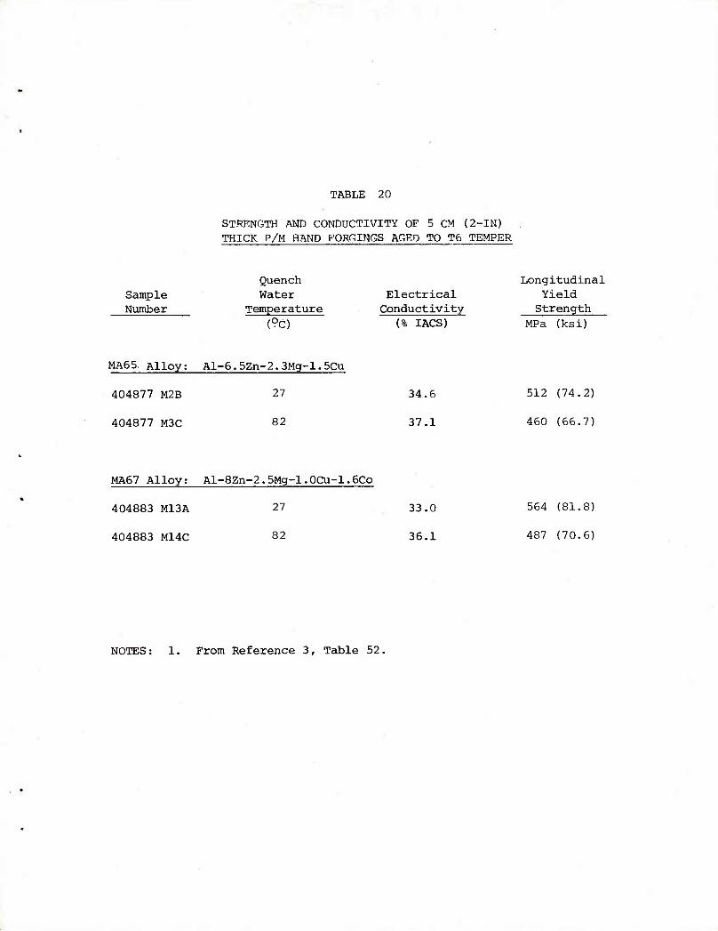
TABLE 20
STRENGTH AND CONDUCTIVITY OF 5 CM (2-IN) THICK P/M HAND FORCINGS AGED TO T6 TEMPER
Sample Number
Quench Water
Temperature (9c)
Electrical Conductivity
(% IACS)
Longitudinal Yield Strength
MPa (ksi)
MA65 Alloy; Al-6.5Zn-2.3Mg-l.5Cu
404877 M2B 27
404877 M3C 82
34.6
37.1
512 (74.2)
460 (66.7)
MA67 Alloy; Al-8Zn-2.5Mg-l.0Cu-l.6Co
404883 M13A 27 33.0
404883 M14C 82 36.1
564 (81.8)
487 (70.6)
NOTES: From Reference 3, Table 52.
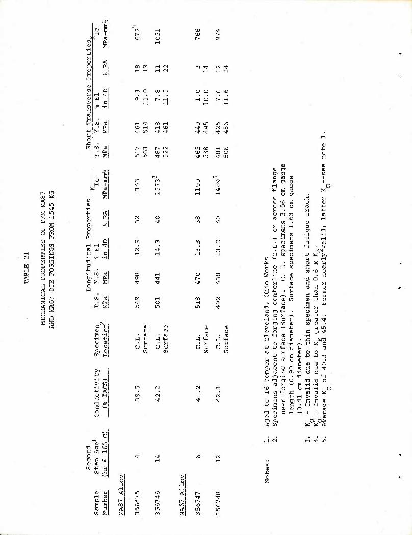
r- o co w g in
<* S ID
\ H fit
s EM o O «
fc CO w M H o En s ^ H H ^3 ft K o o K CM c^
H t-q H a Q o H r~ g U3
i o pq c § § <
CO 9i
■H +J H 0) ft o
01 IB u > a a u
4-1 u o
■c 00
Jf-
D rH <# W
C *> •H
cn id • P^ >H g
(/I rd pb
H S
!!|
m 0)
■H 4J
OJ ft 0
tli
i-H rtJ C
■H ■O 0 4J ■H
s o
w
M
>H"
id PH
s
CO
En
id
c fe QJ 0
.| •H 4-)
0 id 0) o ft 0
CO i-)
u
-H
QJ ro T! (Ji >£i B < H O 0 ft CSJ HI 0)
CO M £
*-"
ft A
m sa
rt
o H
^1" m
CO rH
iH ID CO CN in in M" m
ro n ro <* r- on in
(N O ro <*
ffl ro
CN ■"J1
00 H 01 ^r ^ >*
Ol H '* O un in
a.' a) 0 t) • (T • id
(-1 M- •-I 14-1 • H u U ^ U 3
UJ CO
>1 4-1 •H ^-. > W
■H O in CN ■P rt • U H <Ti CN D CO ■*
■O * c — o u
<*
in lO P» ^ "« r- VO kO in in P0 ro
kO •sf ^j r~ r» ffi
01 CTi H i-H
H CN H CN
ro ■^r CN ^f H CN
ro O oo in o o <o & Oi r-l r> H rH O r- H
oi m in D "* ai CN in
m CO H VD vD ro co o
o Oi 00
00 ro
O
fl O
ro 00
O CO r- 00 ■^ <*
CO CM H m in <*
(U 0) 0 n * id • 01
i-A m hi M-l * ^4 M U 3 U 3
UJ W
CM
0 H H <c r« CO
•^ <* r~- r~- r- H) ^0 ^0 (rf in in g ro ro
QJ +J 0 c
QJ QJ (U Cn 01 CT 3 cn a (0 QJ i cti Cn CJi
rH 3 C MH | (0
Cn , X
w M ^4 Dl iO e 0 QJ 0 in u id 4-1 u • M 4-> 0 ro ro 0 ro id n
^0 QJ
rH
M c H 3 ••■
0 QJ & 13 .jq m •H •H ^-^ G 4-1 rH • 0 QJ (0 id
h^ QJ ft .§ M-H ■pt
u W u +J M >i n QJ SH H ^ t ft 0 X M M cu J m si tO 0 a w iXl QJ s •H • QJ • C
rH U 0 t) o 0 U (0 c u
■H QJ ■4-1 id G QJ ^ 4-1 . M to e o G ^-^ 3 c fl C
QJ QJ CO QJ 4-1 O ■* 0 D P fn
T3 id • H u C tJi MH • CJ QJ id c u ^^ 0) 4-1 • rH •H 3 H ft it) ^r QJ en CO QJ M o . > u 4-1 U in 0) 0 QJ C Cn ^
rH <u QJ ■H
O O n3 . s: wq O CO •H ^^ 4J y, a
4-> 4-1 MH T^ u (0 HI JH 0) O 0
4J 3 s 4-1 4J 4-1 CO SH C UJ 0 Q) • 0) OJ Q) <u o ft 0 Cn o n3 3 p <* g id a ai •H TJ T3 0) ■ro ■H • 13 144
4-1 •a Cn o T3 Ti O <n J4 — g •H -H « O Q rH i-l ( EH w m * id id X
G 4J rH > > 0 0) h Cn ^ c C OJ
4-1 i id C t H H Cn ■H QJ QJ o id
T3 o C rH *— 1 1 u 0) QJ 0) Cn ft Oi cx> i< CO y. y. <
o;
ro ■<* in
o
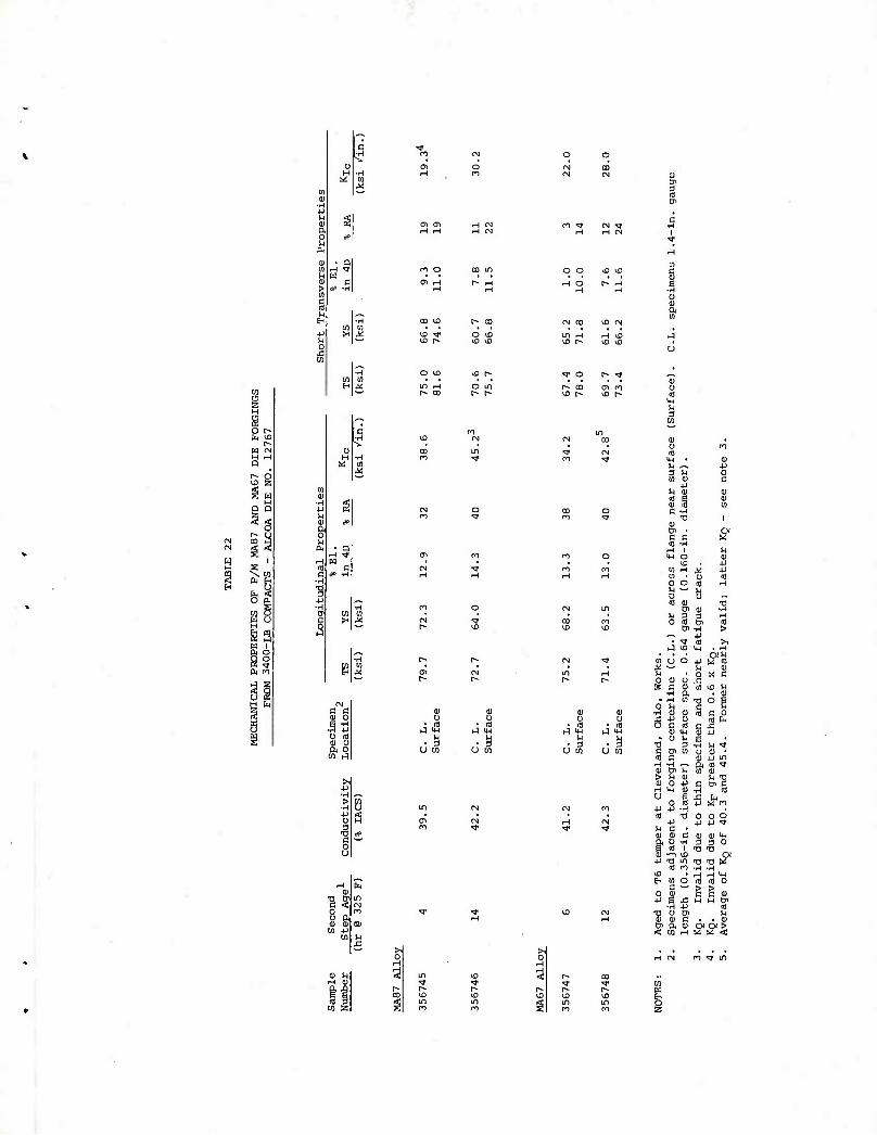
i
• Q
W
i
W
a) o a o
■u ■H >
•H JJ O I a s
c o . u ft a) or W 4J
o CD
n o
W H
H IN H <N
CO en O O i^) ID
tn VD [^ CO
O ID ID ID
O \D ID [^
lO r-l o in co en n
o
0^
CM
g • IB
J l« .1
u tn
o
3 % Oi
0 01 ft
0) u IB in
3 w
a) u m in • u ~ 9 u in a)
•P
-a
c a IB -H H 1 M-l O
ID
o o
iB a)
a) ■p o c
u CD
4J
id
M 5 U
is tn ID
Tl o c IB c o
IB t< .C
0 tH 3
Oi t/1
IB
cu p in ft IB vf tn tu
c en c •H IB J3 ti 4J « ro
0 0 O JJ +J tj.
CU 0) c (U Q) 4-1 ft U -H 3 3 0 id i
^ ^ OI 4J
■n CD TJ m -0 13 KT tB ro ■H -H
CD H H M-l EH tn o IB iB 0
c — > > 0 a) C c m
■U 6 x: H H Oi •H 4J 10
■% U Oi u a) c . , HI
s ft 0) CO H ggz
>l 0
o 2
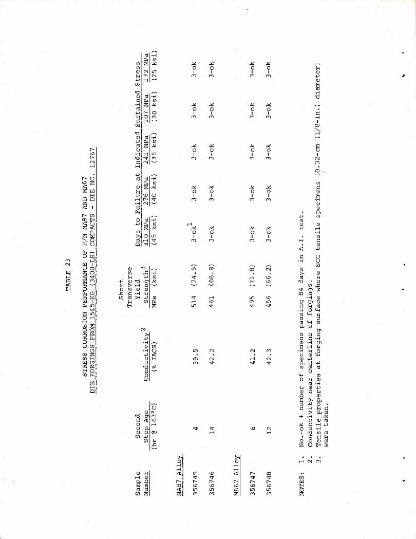
r^ iX) r^ CN H
r- d rf ^ a w
H Q Q
r- en CO H
CM as s \ o PH U
fa ~ O PQ
ro ^ CN 8i ^ Z o J S ^r S s n
H O ~~
fe^ m i Ol LD
i* 2 LD O rH H M S o o « fa o U W
o m s W H
Sg B O CO PM
H M Q
n) ■rH
w s X X w 0 0 0) CM IT) 1 n 1^ CN ro ro +J H — w T) ^^ 0) (0 ■H
C Cu M •3 S Aj ^ ^ ni 0 0 +J r~- o 1 1 to O m o~i ro 3 CN •— M
TJ ^, (U (0 •H +J & [0 ID S M X X 0 0 0
•H H IT) 1 1 ^ ^r ro ro ro C (N — H
-P ^^ to H) •rH
<1) s to
X X M 0 0 3 VO o 1 1 H t^ Tf ro CO •H CN — It P4 _ 0 10 •H
4-) eu M rH s X ^ X
CO 0 0 >1 o in 1 (fl rH <* n ro Q n ~-'
(U -o ^, en ,£1 •H VH 4J w
fl 0) "0 tr 5 U > H a 0 [fl (U OJ * C •rH H w id >H -p fl
H EH
en
>i -P •H > •H -P o p
■n c o u
cu ■a (31 G Ktl 0 u a, ai 0) M -P
w
u
0) M rH QJ ft Q e g 3 ^J w IZ
U3
I--
ro
& ■^
CN
o
X o
o
oo
LTl
cn
CN
rH
>X)
>1 0
rH H < in ^D
^ ^r r- p> r- CO VD ID
S in in g ro ro
X o
I ro
X 0 I ro
0 1
O ■ 1
ro i
m
X 0 1
X 0
1 1 to
1 m
X o
I (O
in
CM
>l 0
rH rH < f- 00
<* ^f [> r~ r> ^D U) ID <J in in g ro ro
0) -p 0)
•H 13
-H I CO
1 CN CO
o '—'
U3 a
o 0) . ft
+J 01 w Q) a)
4-> rH •H m
H
< -p
C u ■H U w >. 0) id M
T) • <u CQ r
'S' Cn 3 CO B
•rH 0) Di CP 0 C M n5
•H 0 UH 0) m M (0 3 rfl 1H w ft 0
Cn 03 (U d C c •rH 0) •H Cr
rH !H •H u O u 0) MH <D -p ft c -P to
0 ai
m to 0 u 0) 3 ■rH
!H 0) -P 0) c in
■g >, 0) ft
3 -p O • C -H M a > ft <D + ■H rV
-P 0) id X 0 rH •p 0 3 •rH
Ti M cu • a a n 0 o a) 0) 2 u H ^
rH Ol ro
w w EH
O s
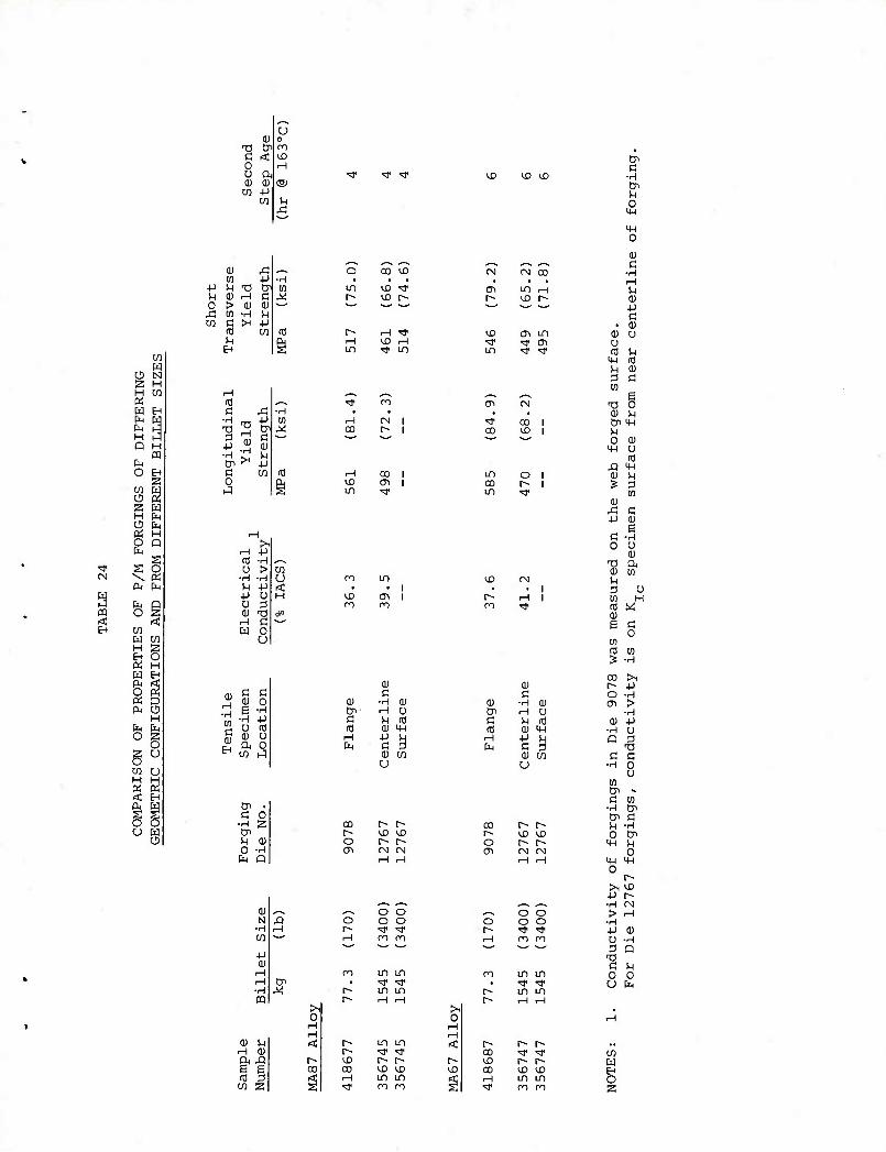
W K
O N S H H C/3 « W En fa W
H hJ Q H
m h O H
z S 2 2 W H fa O Pn Oi H O Q fa
s ^f s o CN \ pg
ft fa
PQ sg a < EH w
m w H 2 EH O ft H fa EH ft < O ft ft D ft 5
H fa fa O 2
O 2 U
CQ U H H ft ft < EH
S s o o u w
Q
OJ o tJ tJI m c < iX) 0 H 0 a, OJ OJ ca
CO +J to
^
u
4-) M 0
M
0)
SH T) Cn
> (U 0)
e x ia u H
H id a £
■3
H OJ
■H
-P
4-) •H
OJ H -p
c w 0 J
M C 0)
c C 0) O e ■rH
■H -P O Ifl <D 0 ft o M hq
Cn , G 0
■H 2 Cn M 0) o •H fa Q
(D H H OJ ft XI S g n3 3 M 2
^
in
in
CO KO
V£) <*
H ■*
■H ^f on
tq H CO
CN 1
w W
d 00 1 <n 1
>l H -P m -H ^-^ o > to
•H -H o ro in U -P rtl • .
■P O H WD ffi O 3 on 00 (U T3 0\» H C —' W 0
u
<U a
0) ■rH 0) Cn H 0 C SH id aj a) MH
rH ■p M fa C P OJ w u
CO p» r> r^ \0 <£> o r- r^ ffi CM CM
^, ^-^ O O XI o O O H r> rjt rji 1— rH 00 ro s~' ^-^
ro uo in Cn « ^f ^ M r- in in
r« iH iH >i 0
rH H < t- in in
p~ ^ '* r- \D i^ r- CD oo vX) iX) prf ^H in in s ■t co oo
kD
c^
CO
VD
oo
iX) lO
CM CO
in i-H iX) r^
iX) cri in i' >^ cn in ^r •st
CO <X)
in o co r- in ^r
C 0) ■H (U tyi rH u c M nj rfl OJ IH
rH -p u fa a 2
0) cn U
00 r> r- [^ ^D ^D o f« r- 01 CN CM
rH rH
^-^ o o O o o r- ^ ■3" rH 00 CO
00 in in < ■=}• >* t» m in r-- rH rH
r~- r~- r> CO ^ ^r ^D r^ r^ cn VD X) rH in UO vr 00 OO
Cn a
■H Cn M O m
m 0
<u c
■rH rH u 0) -p G • 0)
OJ u o rd h
4H rd SH CD 3 a 10
B 13 0
OJ u Cn MH n 0 OJ
M-l 0 ffl
A MH 0) !H s 3
tn cu * c +J 0)
s c •H 0 O
0) ■o ft a> CO u 2 o to H id w QJ e c
0 OT id m s ■rH
00 >1 r> ■P o •rH 0\ >
■H OJ -P
•H O Q 3
T3 a G
■H 0 0
(0 Cn •» C U)
■H Cn Cn C SH ■rH 0 CP m M
O m m 0
r* 5», X) -p r» ■rH Oi > rH
■H -P QJ U •rH 0 Q
■a c u o 0 U fa
w fa O 2
DISTRIBUTION LIST
Office, Chief of Research and Development
Department of the Army ATTN: DARD-ARS-PM Washington, D.C. 20310
Department of Defense ATTN: Advanced Research and
Technology Division Washington, D.C. 20310
Commander U.S. Army Material Development
and Readiness Command 5001 Eisenhower Ave. Alexandria, VA 22333
1 ATTN: DRCMT, Col. N. Vinson
1 ATTN: DRCDMD
1 ATTN: DRCDMR
1 ATTN: DRCDMD-T
1 ATTN: DRCDE-I, Foreign Science and Technology Div.
1 ATTN: DRCDE-W
1 ATTN: DRCMT, Mr. L. Croan
1 ATTN: DRCDE-E, Mr. E. Gardner
1 ATTN: DRCDE-DE, Mr. E. Lippi
Commander U.S. Army Armament Command Rock Island, IL 61201
1 ATTN: Technical Information Div.
1 ATTN: DRSAR-RD, Mr. J. Brinkman
1 ATTN: DRSAR-RDG-A, Mr. J. Williams
1 ATTN: PM, CAWS, Mr. H. Noble
1 ATTN: DRSAR-PPR-1W
1 ATTN: DRSAR-PPI-W, Mr. A. Zahatko
Commander Rock Island Arsenal ATTN: Technical Information Div. Rock Island, IL 61202
Commander, U.S. Army Aviation Systems Command
P.O. Box 209 ATTN: AMSAV-EXT St. Louis, MO 63166
Project Manager, Advanced Attack Helicopter
ATTN: AMCPM-AAH, TM P.O. Box 209 St. Louis, MO 63166
Project Manager, Utility Tactical Transport Aircraft System
ATTN: AMCPM-UA-T P.O. Box 209 St. Louis, MO 63166
Project Manager CH-47 Modernization ATTN: AMCPM-CH47M P.O. Box 209 St. Louis, MO 63166
Project Manager Advanced Scout Helicopter ATTN: AMSAV-SIA P.O. Box 209 St. Louis, MO 63166
Product Manager Aircraft Survivability Equipment ATTN: AMCPM-ASE-TM P.O. Box 209 St. Louis, MO 63166
Product Manager Cobra ATTN: AMCPM-CO-T P.O. Box 209 St. Louis, MO 63166
Product Manager Iranian Aircraft Program ATTN: AMCPM-IAP-T P.O. Box 209 St. Louis, MO 63166
Director Eustis Directorate U.S. Army Air Mobility R&D Lab ATTN: SAVDL-EU-TAS Ft. Eustis, VA 23604
Director, Ames Directorate U.S. Army Air Mobility R&D Lab ATTN: SAVDL-AM Ames Research Center Moffett Field, CA 94035
Director, Langley Directorate U.S. Army Air Mobility R&D Lab ATTN: SAVDL-LA Mail Stop 266 Hampton, VA 23365
Director, Lewis Directorate U.S. Army Air Mobility R&D Lab ATTN: SAVDL-LE 21000 Brook Park Road Cleveland, OH 44135
Commander U.S. Army Electronics Command Ft, Monmouth, NJ 07703
1 ATTN: TECHNICAL INFORMATION DIV.
1 ATTN: AMSEL-RD-P
Commander U.S. Army Missile Command Redstone Arsenal, AL 35809
1 ATTN: DRSMI-IIE
1 ATTN: DRSMI-RSM
1 ATTN: TECHNICAL INFORMATION DIV.
Commander U.S. Army Troop Support Command 4300 Goodfellow Blvd. St. Louis, MO 63120
Commander U.S. Army Tank-Automotive Command Warren, MI 48090 ATTN: AMSTA-RCM.l
1 ATTN: AMSTA-RKA, MR. V. PAGANO
Commander U.S. Army Materials & Mechanics
Research Center Watertown, MA 02172
1 ATTN: DMXMR, DR. E. WRIGHT
1 ATTN: DMXMR-PT
1 ATTN: TECHNICAL INFORMATION DIV.
Commander Picatinny Arsenal Dover, NJ 07801
1 ATTN: PM, SELECTED AMMUNITION
1 ATTN: SARPA-AD
1 ATTN: SARPA-FR-M
1 ATTN: TECHNICAL INFORMATION DIV.
Project Manager for Munition Production Base Modernization and Expansion 1 ATTN: DRCPM-PBM-M, MR. H. KROSSER 1 ATTN: DRCPM-PBM-M Dover, NJ 07801
Commander Watervliet Arsenal Watervliet, NY 12189
1 ATTN: SARWV-RDR, DR. T. E. DAVIDSON
1 ATTN: TECHNICAL INFORMATION DIV.
Commander U.S. Army Research Office P.O. Box 12211 1 ATTN: DR. GEORGE MAYER, DIRECTOR Metallurgy & Materials Science Div. Research Triangle Park, NC 27709
1 ATTN: AMSTS-PLC
Commander U.S. Army Research and
Standardization Group (Europe) 1 ATTN: DRXSN-E-RM, DR. R. QUATTRONE Box 65 FPO, New York 04510
Commander Aberdeen Proving Ground Aberdeen, MD 21005
1 ATTN: STEAP-TL, TECHNICAL LIBRARY
1 ATTN: AMXBR-TB-E, DR. E. BLOORE
Commander Harry Diamond Laboratories 2800 Powder Mill Road 1 ATTN: AMXDO-TIB Adelphi, MD 20783
Commander U.S. Army Mobility Equipment
Research and Development Command 1 ATTN: DRXFB-VM Ft. Belvoir, VA 22060
Commander Redstone Arsenal 1 ATTN: TECHNICAL INFORMATION DIV. Huntsville, AL 35809
Commander Rocky Mountain Arsenal 1 ATTN: TECHNICAL INFORMATION DIV. Denver, CO 80240
Commander U.S. Army Natick Research and
Development Command 1 ATTN: TECHNICAL INFORMATION DIV. Natick, MA 07160
Commander Edgewood Arsenal 1 ATTN: TECHNICAL INFORMATION DIV. Edgewood, MD 21005
Director U.S. Army Industrial Base
Engineering Activity 1 ATTN: DRXIB-MT, MR. G. NEY 1 ATTN: DRXPE, MR. J. GALLAUGHER Rock Island, IL 61201
Commander U.S. Army Foreign Science &
Technology Center 1 ATTN: MR. W. F. MARLEY 220 - 7th Street, N.E. Charlottesville, VA 22901
Director Air Force Armament Laboratory 1 ATTN: AFATL/DLOSL Eglin AFB, FL 32542
Director Air Force Materials Laboratory Wright-Patterson AFB Dayton, OH 45433
1 ATTN: AFML, DR. T. M. F. RONALD
1 ATTN: AFML, TECHNICAL LIBRARY
1 ATTN: AFML/LTM, MR. N. KLARQUIST
1 ATTN: AFML/LTN
1 ATTN: AFML/LTE
1 ATTN: AFML/LLN, DR. V. RUSSO
1 ATTN: AFML/LLS, MR. W. GRIFFITH
Director Air Force Weapons Laboratory 1 ATTN: TECHNICAL INFORMATION DIV. Kirtland AFB, NM 87118
Commander Naval Air Systems Command Department of the Navy ATTN: AIR 5203, MR. R. SCHMIDT Washington, D.C. 20361
Commander Naval Ships Systems Command Department of the Navy ATTN: CODE 03423 Washington, D.C. 20025
Commander Office of Naval Research Department of the Navy ATTN: CODE 423 Washington, D.C. 20025
Commander U.S. Naval Weapons Laboratory ATTN: TECHNICAL INFORMATION DIV. Dahlgren, VA 22448
Commander Naval Air Development Center
Johnsville Aero Materials Dept. ATTN: MR. F. WILLIAMS Warminster, PA 18974
Chief, Bureau of Ships Department of the Navy ATTN: CODE 343 Washington, D.C. 20025
Chief, Bureau of Aeronautics Department of the Navy ATTN: TECHNICAL INFORMATION DIV. Washington, D.C. 20025
Chief, Bureau of Weapons Department of the Navy ATTN: TECHNICAL INFORMATION DIV. Washington, D.C. 20025
Commander U.S. Naval Engineering Experimental
Station ATTN: WCTRL-2, MATERIALS LAB Annapolis, MD 21402
Commander Air Research and Development Command Andrews Air Force Base ATTN: RDRAA Washington, D.C. 20025
Commander U.S. Naval Ordnance Laboratory ATTN: CODE WM Silver Spring, MD 20910
Director U.S. Army Advanced Materials
Concept Agency ATTN: TECHNICAL INFORMATION DIV. 2461 Eisenhower Avenue Alexandria, VA 22314
Director U.S. Naval Research Laboratory ATTN: MR. W. S. PELLINI
Code 6300, Metallurgy Div. Washington, D.C. 20390
Director
Naval Ships Research and Development Center
ATTN: MR. A. R. WILLMER, Chief of Metals Research
Bethesda, MD 20034
Commander U.S. Naval Ordnance Station ATTN: CODE FS-72C, MR. T. MYCKA Indianhead, MD 20640
Director Defense Advanced Research Projects Agency
ATTN: Dr. E. C. Van Reuth 1400 Wilson Blvd. Arlington, VA 22209
Director National Academy of Science ATTN: MATERIALS ADVISORY BOARD 2101 Constitution Ave., N.W. Washington, D.C. 20418
Director National Aeronautics and Space Administration
ATTN: CODE RRM Federal Building No. 10 Washington, D.C. 20546
Director National Aeronautics and Space Administration
George C. Marshall Space Flight Center 1 ATTN: M-F&AR-M, MR. W. WILSON Huntsville, AL 35800
Director National Bureau of Standards ATTN: TECHNICAL INFORMATION DIV. Washington, D.C. 20025
Director U.S. Atomic Energy Connnission ATTN: DOCUMENT LIBRARY Germantown, MD 21403
Federal Aviation Administration ATTN: ADMINISTRATIVE STANDARD DIV. 800 Independence Ave., S.W. Washington, D.C. 20590
Metals and Ceramic Information Ctr. Battelle Memorial Institute 505 King Avenue Columbus, OH 43201
12 Defense Documentation Center Cameron Station ATTN: DDC-TCA Alexandria, VA 22314
Hughes Helicopter Division of Summa Corp. ATTN: MR. R. E. MOORE, BLDG. 314 M/S T-419 Centinella Ave. & Teale St. Culver, City, CA 90230
Sikorsky Aircraft Division United Aircraft Corp. ATTN: MR. S. SILVERSTEIN Section Supv., Mfg. Tech. Stratford, CT 06497
Bell Helicopter Co. ATTN: MR. P. BAUMGARTNER, CHIEF,
MANUFACTURING TECHNOLOGY P.O. Box 482 Ft. Worth, TX 76101
Kaman Aerospace Corp. ATTN: MR. A. S. FALCONE
CHIEF, MATERIALS ENGRG. Bloomfield, CT 06002
Boeing Vertol Company ATTN: MR. R. PINCKNEY, MFG. TECH. Box 16858 Philadelphia, PA 19142
Mr. R. H. Brown 1411 Pacific Ave. Natrona Heights, PA 15065
Dr. R. S. Busk 3606 Windsor Court Midland, MI 48640
Mr. J. B. Hess Kaiser Aluminum & Chemical Corp. Aluminum Division Research Center
for Technology P. O. Box 870 Pleasanton, CA 94566
Prof. G. R. Irwin University of Maryland College Park, MD
Dr. S. Radtke International Lead Zinc Institute 292 Madison Avenue New York, NY 10017
Prof. M. C. Flemings Department of Metallurgy Materials Science Mass. Institute of Technology Cambridge, MA 02139
Mr. C. L. Brooks Reynolds Metal Company 4th and Canal Streets Richmond, VA 23219
Mr. H. Y. Hunsicker Aluminum Co. of America Alcoa Technical Center Alcoa Center, PA 15069
Prof. J. Kenig Drexel University Philadelphia, PA 19104
Dr. E. J. Ripling Materials Research Laboratory, Inc. No. 1 Science Road Glenwood, IL 60425
Prof. H. Rogers Drexel University Philadelphia, PA 19104
Dr. L. W. Eastwood Rt. 2 Woodfield, OH 43793
Dr. W. Rostoker University of Illinois College of Engineering Box 4348 Chicago, IL 60680
Mr. J. C. Zola Boeing Vertol Company P. o. Box 16858 Philadelphia, PA 19142
Prof. C. Laird Dept. of Metallurgy and Materials Science
University of Pennsylvania Philadelphia, PA 19174
Mr. R. E. Newcomer Dept. 247, Bldg. 32 McDonnell Douglas Corporation P. 0. Box 516 St. Louis, MO 63166
Mr. H. C. Turner
Branch Manager, Metallic Materials Dept. 372, Bldg. 33 McDonnell Douglas Aircraft Corp. P. 0. Box 516 St. Louis, MO 63166
Mr. G. G. Wald Dept. 78-40, Bldg. 63, Plant A-l Lockheed Aircraft Company P. 0. Box 551 Burbank, CA 91503
Mr. M. V. Hyatt Organisation B-8833 Mail Stop 73-43 The Boeing Company P. 0. Box 3707 Seattle, WA 98124
Prof. R. Mehrabian University of Illinois at
Urbana - Champaign Urbana, IL 61801
Mr. E. Laich Kawecki Berylco Industries, Inc. 220 East 42nd Street New York, NY 10017
Dr. N. Paton Rockwell International Science Center Thousand Oaks, CA
Commander Frankford Arsenal Philadelphia, PA 19137
15 ATTN: PDM-P, L3100, BLDG. 513, DR. J. WALDMAN
2 ATTN: MTT, T100, BLDG. 211-2
Mr. P. Mackmeier Materials Technology MZ2860 General Dynamics Corporation Ft. Worth Division Ft. Worth, TX 76010