o & m manual for the atc-100 breaker based transfer switch
TRANSCRIPT
IB01602
O & M Manual for the ATC-100 Breaker Based Transfer SwitchInstructional Booklet
018E For more information visit
Description Page
1. Introduction . . . . . . . . . . . . . . . . . . . . . . . . . . . . . . . 22. Receiving, Handling, and Storage . . . . . . . . . . . . . . . . 63. Equipment Description . . . . . . . . . . . . . . . . . . . . . . . . 64. Installation and Wiring . . . . . . . . . . . . . . . . . . . . . . . . 145. Operation . . . . . . . . . . . . . . . . . . . . . . . . . . . . . . . . . 246. Testing and Problem Solving. . . . . . . . . . . . . . . . . . . . 267. Adjustments . . . . . . . . . . . . . . . . . . . . . . . . . . . . . . . 278. Maintenance. . . . . . . . . . . . . . . . . . . . . . . . . . . . . . . 289. Renewal Parts Guide . . . . . . . . . . . . . . . . . . . . . . . . . 2910. ATC-100 Controlled ATS Quick Start Instructions . . . . 3111. Appendix A: Pickup / Dropout Tables. . . . . . . . . . . . . 39
:
www.eaton.com
O & M Manual for theATC-100 Breaker Based Transfer Switch
Instructional BookletPage 2 Effective: March 2014
Figure 1. Typical Automatic Transfer Switch (ATS) Equipment Nameplate.
All possible contingencies that may arise during installation, opera-tion, or maintenance, and all details and variations of this equip-ment do no purport to be covered by these instructions. If further information is desired by the purchaser regarding a particular installation, operation, or maintenance of particular equipment, please contact an authorized Eaton Sales Representative or the installing contractor.
Section 1:Introduction1.1 Preliminary Comments and Safety Precautions
This technical document is intended to cover most aspects associ-ated with the installation, application, operation, and maintenance of the Automatic Transfer Controller (ATC-100) Controlled ATS with ratings from 30 through 600 amperes (A). It is provided as a guide for authorized and qualified personnel only. Please refer to the specific WARNING and CAUTION in Section 1.1.2 before pro-ceeding. If further information is required by the purchaser regard-ing a particular installation, application, or maintenance activity, please contact an authorized Eaton sales representative or the installing contractor.
1.1.1 Warranty and Liability Information
No warranties, expressed or implied, including warranties of fit-ness for a particular purpose of merchantability, or warranties aris-ing from course of dealing or usage of trade, are made regarding the information, recommendations and descriptions contained herein. In no event will Eaton be responsible to the purchaser or user in contract, in tort (including negligence), strict liability or otherwise for any special, indirect, incidental or consequential damage or loss whatsoever, including but not limited to damage or loss of use of equipment, plant or power system, cost of capital, loss of power, additional expenses in the use of existing power facilities, or claims against the purchaser or user by its customers resulting from the use of the information and descriptions con-tained herein.
1.1.2 Safety Precautions
All safety codes, safety standards, and/or regulations must be strictly observed in the installation, operation, and maintenance of this device.
WARNINGREAD AND UNDERSTAND THE INSTRUCTIONS CONTAINED HEREIN-AFTER BEFORE ATTEMPTING TO UNPACK, ASSEMBLE, OPERATE, OR MAINTAIN THIS EQUIPMENT.
HAZARDOUS VOLTAGES ARE PRESENT INSIDE TRANSFER SWITCH ENCLOSURES THAT CAN CAUSE DEATH OR SEVERE PERSONAL INJURY. FOLLOW PROPER INSTALLATION, OPERATION, AND MAINTENANCE PROCEDURES TO AVOID THESE VOLTAGES.
TRANSFER SWITCH EQUIPMENT COVERED BY THIS INSTRUCTION BOOK IS DESIGNED AND TESTED TO OPERATE WITHIN ITS NAME-PLATE RATINGS. OPERATION OUTSIDE OF THESE RATINGS MAY CAUSE THE EQUIPMENT TO FAIL RESULTING IN DEATH, SERIOUS BODILY INJURY, AND/OR PROPERTY DAMAGE. ALL RESPONSIBLE PERSONNEL SHOULD LOCATE THE DOOR MOUNTED EQUIPMENT NAMEPLATE AND BE FAMILIAR WITH THE INFORMATION PRO-VIDED ON THE NAMEPLATE. A TYPICAL EQUIPMENT NAMEPLATE IS SHOWN IN FIGURE 1.
EAutomatic Transfer Switch
Cat No: ATV1LDA20400WRU 2/04GO No: XYZ0123 1/1Item 1
Poles: 2 Amps: 225 Volt: 240Phase: 1 Hertz: 60 Wire: 3
WARNINGTHE WARNINGS AND CAUTIONS INCLUDED AS PART OF THE PRO-CEDURAL STEPS IN THIS DOCUMENT ARE FOR PERSONNEL SAFETY AND PROTECTION OF EQUIPMENT FROM DAMAGE. AN EXAMPLE OF A TYPICAL WARNING LABEL HEADING IS SHOWN ABOVE TO FAMILIARIZE PERSONNEL WITH THE STYLE OF PRESENTATION. THIS WILL HELP TO INSURE THAT PERSONNEL ARE ALERT TO WARNINGS, WHICH APPEAR THROUGHOUT THE DOCUMENT. IN ADDITION, WARNINGS AND CAUTIONS ARE ALL UPPER CASE AND BOLDFACE.
CAUTIONCOMPLETELY READ AND UNDERSTAND THE MATERIAL PRESENTED IN THIS DOCUMENT BEFORE ATTEMPTING INSTALLATION, OPERA-TION, OR APPLICATION OF THE EQUIPMENT. IN ADDITION, ONLY QUALIFIED PERSONS SHOULD BE PERMITTED TO PERFORM ANY WORK ASSOCIATED WITH THIS EQUIPMENT. ANY WIRING INSTRUCTIONS PRESENTED IN THIS DOCUMENT MUST BE FOL-LOWED PRECISELY. FAILURE TO DO SO COULD CAUSE PERMA-NENT EQUIPMENT DAMAGE.
For more information visit: www.eaton.com IB01602018E

Instructional BookletEffective: March 2014 Page 3
O & M Manual for the ATC-100 Breaker Based Transfer Switch
1.2 General Information
Transfer switches are used to protect critical electrical loads against loss of power. The load’s Utility power source is backed up by a Generator power source. A transfer switch is connected to both the Utility and Generator power sources and supplies the load with power from one of the two sources. In the event that power is lost from Utility, the transfer switch transfers the load to the Generator power source. This transfer can be automatic or manual, depending upon the type of transfer switch equipment being used. Once Utility power is restored, the load is automati-cally or manually transferred back to the Utility power source, again depending upon the type of transfer equipment being used (Figure 2).
Figure 2. Typical Load Transfer Switch (Circuit Breaker Type) Schematic.
In ATS equipment, the switch’s intelligence system initiates the transfer when the Utility power fails, or falls below a preset volt-age. If the Generator power source is a standby generator, the ATS initiates generator startup and transfers to the Generator power source when sufficient generator voltage is available. When Utility power is restored, the ATS automatically transfers back and initiates generator shutdown. In the event the Utility power source fails and the Generator power source does not appear, the ATS remains connected to the Utility power source until the Generator power source does appear. Conversely, if con-nected to the Generator power source and the Generator power source fails while the Utility power source is still unavailable, the ATS remains connected to the Generator power source.
ATSs automatically perform the transfer function, and include three basic elements:
1. Main contacts to connect and disconnect the load to and from the power source.
2. A mechanism to transfer the main contacts from source to source.
3. Intelligence/supervisory circuits to constantly monitor the con-dition of the power sources and thus provide the intelligence necessary for the switch and related circuit operation.
1.2.1 Design Configuration
The Eaton ATS is a rugged, compact design that uses molded case switches and/or circuit breakers to transfer essential loads from one power source to another (Figures 3 [225-600 A] and 4 [30-150 A]). Molded case switches are mechanically and electri-cally interlocked to prevent both switching devices from being closed at the same time.
Figure 3. Typical Power Panel for 225-600 A Models (Deadfront Covers Removed).
Utility
Generator
Load
IB01602018E For more information visit: www.eaton.com

O & M Manual for theATC-100 Breaker Based Transfer Switch
Instructional BookletPage 4 Effective: March 2014
Figure 4. Typical Power Panel for 30-150 A Models (Deadfront Cover Installed).
Molded case switches and the associated transfer mechanisms are mounted vertically to save space in the assembly. The com-pact, vertical configuration uses a positive, metallic transfer and interlocking system between the molded case switches.
The Eaton ATS was designed with easy installation and simplified maintenance in mind. Three main panels compromise the transfer switch design:
1. Power panel; 2. Voltage selection and transformer panel (if required); and 3. Microprocessor-based logic panel.
Figure 5. Vertical Design Transfer Switch with the Deadfront Cover in Place Over the Power Panel (225-600 A).
Each panel is independently mounted with interconnecting wiring terminated at the connector receptacles on the ATC-100 Control-ler. Door or individual panel removal is achieved without disturb-ing critical connections by removing the connectors from the receptacles and cutting the wire ties that secure the wires to the door.
Mounting the enclosure is simple using top and bottom mounting flanges with elongated (teardrop) mounting holes. These mount-ing holes, along with power panel positioning bolts and pre-tapped inserts, insure proper power panel mounting after the initial enclo-sure installation or when switching from top to bottom or bottom to top entry. Refer to Section 4 for specific mounting and modifi-cation details.
Table 1. Withstand Ratings
1.3 ATS Catalog Number Identification
Transfer switch equipment catalog numbers provide a significant amount of relevant information that pertains to a particular piece of equipment. The Catalog Number Identification Table (Table 2) provides the required interpretation information. An example is offered here to initially simplify the process.
Example:Catalog Number (circled numbers correspond to position headings in Table 2):
1 to 2 3 4 5 to 6 7 8 9 to 12 13 14 15
AT V 1 LD A 2 0400 W R U
The catalog number ATV1LDA20400WRU describes an ATS with the switching devices mounted vertically in the enclosure. The intelligence represented by the control panel is ATC-100 logic. The Eaton Series C Type HLD is used as the switching device and is in the form of a 2-pole molded case switch on each source. The continuous current rating of this equipment is 400 A and applica-ble at 240 Vac, 60 Hz. The transfer switch equipment is enclosed in a NEMA 3R enclosure and is listed for UL applications.
POWER PANEL PANEL
VOLTAGE SELECTIONAND TRANSFORMER PANEL
LOGIC
UL 1008 WITHSTAND AND CLOSE-ON RATINGS (kA)
SwitchRatingAmperes
UL 1008 3-Cycle“Any Breaker” Rating
Rating When UsedWith Upstream Fuse
240 Vac 480 Vac 600 VacMaximumFuse Rating
FuseType 600 Vac
30-100150150-225225
100100100100
656565 (240 Vac)65
25252525
200400400400
J, TJ, TJ, TJ, T
200200200200
300400600
100100100
656565
252525
4006001200
J, TJ, TJ, T
200200200
8001000
6565
5050
2525
16001600
LL
200200
4 pole 480 Vac are rated 35 kA
For more information visit: www.eaton.com IB01602018E

Instructional BookletEffective: March 2014 Page 5
O & M Manual for the ATC-100 Breaker Based Transfer Switch
Table 2. Transfer Switch Catalog Number Explanation
Notes: 1 Vertical orientation (225-600 A)2 Horizontal orientation (30-225 A)3 Consult factory for availability.* 600A available at 240 VAC only.
1.4 Environmental Conditions
1.4.1 Operational Conditions
Normally, an ATS is applied indoors in an electrical equipment room. In the appropriate enclosure, it can be used for outdoor applications were the equipment is subject to falling rain, freezing temperatures, and no greater than 90% humidity (non-condens-ing). The ambient temperature range for operation is between -20 and 70°C (-4 to 158°F).
1.5 Glossary
With respect to their use within this document and as they relate to transfer switch and controller operation, the following terminol-ogy is defined.
AvailableA source is defined as “available” when it is within its undervolt-age/underfrequency/overfrequency (if applicable) setpoint ranges for the nominal voltage and frequency setting.
ConnectedConnected is defined as when the input is shorted by an external contact or connection.
Failed or FailsA source is defined as “failed” when it is outside of the applicable voltage and frequency setpoint ranges for the nominal voltage and frequency setting for a time exceeding 0.5 seconds after the time delay emergency fail (TDEF) time delays expires.
FailsafeFailsafe is a feature that prevents disconnection from the only available power source and also forces a transfer or re-transfer operation to the only available power source.
Re-TransferRe-transfer is defined as a change of the load connection from the Generator to the Utility.
UtilityUtility is the primary source (normal source, normal power source, or normal).
GeneratorGenerator is the secondary source (generator emergency source, emergency power source, emergency, standby, or backup source).
Utility: Failed or FailsUtility is defined as “failed” when it is outside of its undervoltage setpoint ranges for the nominal voltage and frequency setting.
Generator: Failed or FailsGenerator is defined as “failed” when it is outside of its undervolt-age/underfrequency/overfrequency (if applicable) setpoint ranges for the nominal voltage and frequency setting for a time exceeding 0.5 seconds after the Time Delay Emergency Fail (TDEF) time delay expires.
TransferTransfer is defined as a change of the load connection from the Utility to the Generator power source.
Transfer to NeutralTransfer to Neutral is defined as when the load circuits are discon-nect from both the Utility and Generator power sources.
UnconnectedUnconnected is defined as when the input is not shorted by an external contact or connection.
POSITIONS 1 TO 2
BASICDEVICE
POSITION 3 POSITION 4
CONTROLPANEL
POSITIONS 5 TO 6
SWITCHINGDEVICE
SWITCHING DEVICEORIENTATION
Automatic Transfer Switch AT Vertical V1 Horizontal H2
ATC-100Controller
1 HFDHKDHLD
Eaton Series CEaton Series CEaton Series C
FDKD LD
POSITION 7 POSITION 8 POSITIONS 9 TO 12 POSITION 13 POSITION 14 POSITION 15
SWITCHING DEVICEARRANGEMENT
NUMBEROF POLES
AMPERERATING
VOLTAGE/FREQUENCY ENCLOSURE LISTING
Fixed Mount Molded Case A Two 2 30 A – 0030 600 Vac/60 Hz E Type 12 J UL/CSA Listing U
Switches Both Power Sources Three 3 70 A – 0070 480 Vac/60 Hz X Type 3R R No Listing X
Four 4 100 A – 0100 240 Vac/60 Hz W Open K
150 A – 0150 208 Vac/60 Hz B
200 A – 0200 120 Vac/60 Hz A
225 A – 0225
300 A – 0300
400 A – 0400
* 600 A – 0600
IB01602018E For more information visit: www.eaton.com
O & M Manual for theATC-100 Breaker Based Transfer Switch
Instructional BookletPage 6 Effective: March 2014
Section 2: Receiving, Handling, and Storage2.1 Receiving
Every effort is made to ensure that the ATS equipment arrives at its destination undamaged and ready for installation. Packing is designed to protect internal components as well as the enclosure. Care should be exercised, however, to protect the equipment from impact at all times. Do not remove the protective packaging until the equipment is ready for installation.
When the ATS equipment reaches its destination, the customer should inspect the shipping container for any obvious signs of rough handling and/or external damage that occurred during trans-portation. Record any external and internal damage for reporting to the transportation carrier and Eaton, once a thorough inspection is complete. All claims should be as specific as possible and include the Catalog Order and General Order numbers.
A shipping label affixed to the shipping container includes a vari-ety of equipment and customer information, such as General Order Number and Customer Number. Make certain that this information matches other shipping paper information.
Each transfer switch enclosure is bolted through its top and bot-tom mounting flanges to a rigid wooden pallet. The pallet is open at two ends for movement by a forklift. Heavy-duty cardboard sides surround the enclosure and are further supported with rein-forced cardboard corner posts. An egg crate design cardboard protector covers the entire top of the enclosure with additional cardboard protectors over the indicating light panel and operating handle. A heavy-duty cardboard lid covers the entire opening. The shipment is secured and further protected with shrink-wrap. Do not remove or discard the packing material until the equipment is ready for installation.
Once the top packaging is removed from the shipment, the enclo-sure door can be opened. A plastic bag of documents will be found in the enclosure, usually attached to the inside of the door. Important documents, such as test reports, wiring diagrams, and appropriate instruction leaflets, are enclosed within the bag and should be filed in a safe place.
2.2 Handling
As previously mentioned, ATS equipment is packaged for forklift movement. Protect the equipment from impact at all times and DO NOT double stack.
Once the equipment is at the installation location and ready to be installed, packaging material can be removed and discarded. Once the enclosure is unbolted from the wooden pallet, it can be hand moved to its installation position. Be careful not to damage the top or bottom enclosure mounting flanges. Refer to Section 4 of this manual for specific installation instructions.
2.3 Storage
Although well packaged, this equipment is not suitable for outdoor storage. The equipment warranty will not be applicable if there is evidence of outdoor storage. If the equipment is to be stored indoors for any period of time, it should be stored with its protec-tive packaging material in place. Protect the equipment at all times from excessive moisture, construction dirt, corrosive condi-tions, and other contaminants.
It is strongly suggested that the package-protected equipment be stored in a climate-controlled environment with temperatures from -30 to 85°C (-22 to 185°F) and with a relative humidity of 80% or less. DO NOT, under any circumstance, stack other equipment on top of a transfer switch equipment enclosure, whether pack-aged or not.
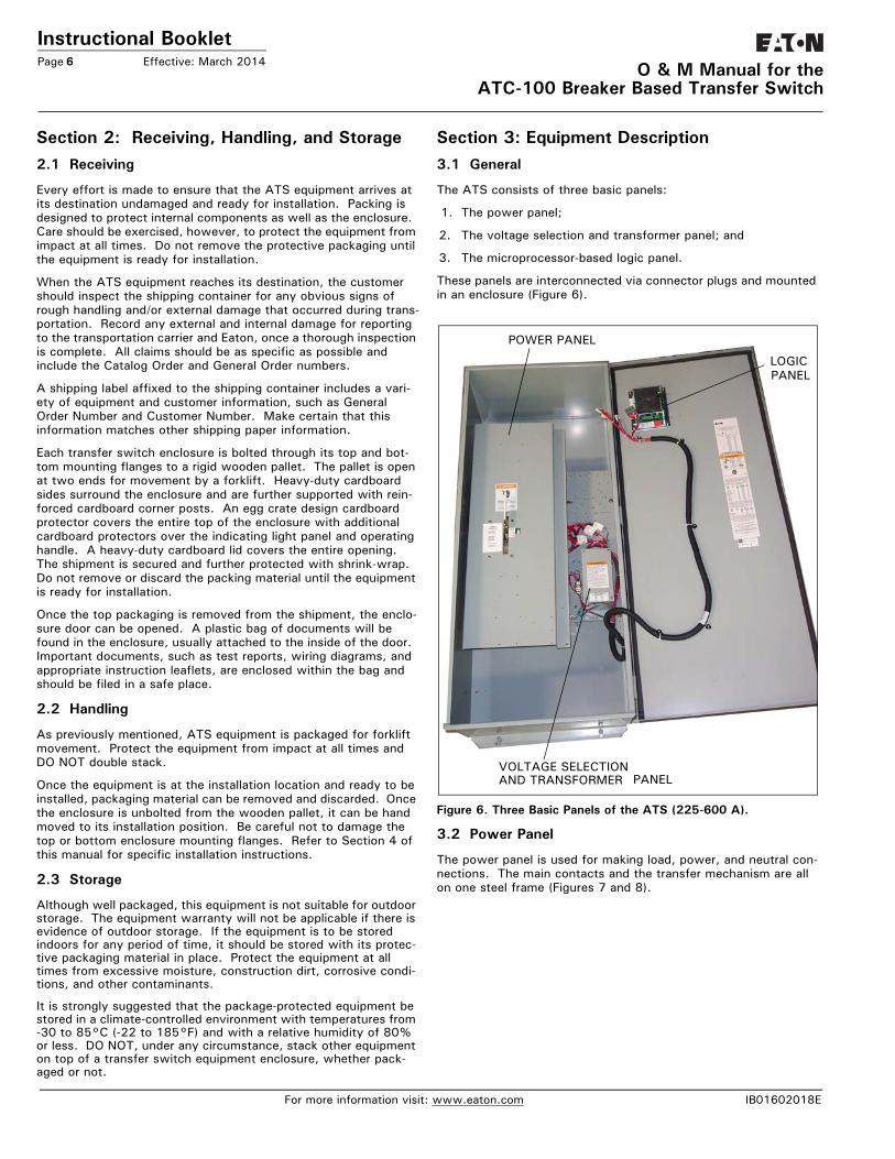
Section 3: Equipment Description3.1 General
The ATS consists of three basic panels:
1. The power panel;
2. The voltage selection and transformer panel; and
3. The microprocessor-based logic panel.
These panels are interconnected via connector plugs and mounted in an enclosure (Figure 6).
Figure 6. Three Basic Panels of the ATS (225-600 A).
3.2 Power Panel
The power panel is used for making load, power, and neutral con-nections. The main contacts and the transfer mechanism are all on one steel frame (Figures 7 and 8).
POWER PANEL
LOGICPANEL
VOLTAGE SELECTIONAND TRANSFORMER PANEL
For more information visit: www.eaton.com IB01602018E

Instructional BookletEffective: March 2014 Page 7
O & M Manual for the ATC-100 Breaker Based Transfer Switch
Figure 7. Typical Power Panel for 225-600 A Models.
Figure 8. Typical Power Panel for 30-150 A Models.
3.2.1 Steel Base Plate
The steel base plate design (225-600 A models only) permits the power panel to be moved vertically within the enclosure to accom-modate top or bottom cable entry. Elongated holes on either side of the base plate ensure proper positioning. The bottom set of
elongated holes positions the power panel higher in the enclosure, thus permitting bottom cable entry. The top set of elongated holes positions the power panel lower in the enclosure for top cable entry. Section 4 discusses equipment mounting and load lug location in detail.
3.2.2 Main ContactsThis ATS incorporates Eaton-type molded case switches. The main contacts connect and disconnect the load to and from the different power sources. High-withstand molded case switches are the main contacts for the Utility and Generator power sources in standard switch ATSs (Figure 9 and Section 3.7). These con-tinuous duty transfer switches are rated for all classes of loads, open or enclosed.
Figure 9. Mounted Molded Case Switches with the Transfer Mechanism Removed for Clarity (225-600 A Models).
In addition, they have high dielectric strength, heavy-duty switch-ing, high-withstand capabilities, and high interruption capacity.
The switching devices are mechanically and electrically inter-locked to prevent the two sets of main contacts from being closed simultaneously. The load side contacts of each switching device are joined with a bus bar assembly to form a common load termi-nal location, either top or bottom (Figures 10 and 11).
IB01602018E For more information visit: www.eaton.com

Instructional BookletPage 8 Effective: March 2014
O & M Manual for theATC-100 Breaker Based Transfer Switch
Figure 10. Typical (30-150 A) Horizontal Design Transfer Switch Equipment (Door Open).
NORMAL POWERSOURCE SWITCHINGDEVICE
NORMAL LINECONNECTIONS
MANUAL OPERATORKNOB
BRAKE RELEASELEVER
NEUTRAL BOND(FOR SERVICE
NEUTRALASSEMBLY
GROUNDCONNECTIONS
TRANFERMECHANISM
EMERGENCY LINECONNECTIONS
EMERGENCY POWERSOURCE SWITCHINGDEVICE
PIVOTBOLT
LOADCONNECTIONS
ENTRANCE)
For more information visit: www.eaton.com IB01602018E

Instructional BookletEffective: March 2014 Page 9
O & M Manual for the ATC-100 Breaker Based Transfer Switch
Figure 11. Typical (225-600 A) Vertical Design Transfer Switch Equipment (Door Open and Deadfront Cover Removed).
3.2.3 Transfer Mechanism (225-600 A)
The transfer mechanism transfers between power sources through a motor-driven, ratchet-type operation. A rotational motion is created on an indicator wheel by the ratchet’s opera-tion. The indicator wheel is attached to rigid shafts that convert the rotary motion into vertical linear motion. Opening and closing the switching devices is accomplished as a result of this vertical linear motion. The transfer mechanism is mounted in front of the molded case switches (Figure 11).
NORMAL POWERSOURCE MOLDEDCASE SWITCH
GROUNDCONNECTIONS
MANUAL OPERATINGHANDLE
INDICATORWHEEL
TRANSFERMECHANISM
MOTOR BRAKEBOARD
EMERGENCY POWER SOURCEMOLDED CASE SWITCH
NEUTRALCONNECTIONS
LOAD LUGS (TOP ENTRY) POWER PANEL
IB01602018E For more information visit: www.eaton.com

O & M Manual for theATC-100 Breaker Based Transfer Switch
Instructional BookletPage 10 Effective: March 2014
A solid steel shield (Deadfront Cover) attached to the ratchet assembly permits viewing of the rotary switch position indicator while restricting access to other parts of the power panel (Figure 12).
Figure 12. Vertical Design ATS Equipment with Deadfront Cover in Place Over the Power Panel (225-600 A).
3.2.4 Transfer Mechanism (30-150 A)
This mechanism transfers between power sources using a motor-driven arm that connects to a lever that operates both the Utility and Generator switches (Figure 8).
3.3 Voltage Selection
3.3.1 North American Voltage Selection (120, 208, 240, 480, and 600 V, - 60 Hz)
The North American market voltage selection panel consists of multi-tap transformers, contained in a steel case mounted in the enclosure (Figure 13). The cover has “teardrop” holes for the screws to allow easy access to the transformers. The voltage is selected by simply removing the wires from the default primary taps of both transformers and installing them on the primary taps for the desired voltage. Taps are provided for 120 to 600 Vac to satisfy any required North American market application voltage. The factory default position is 600 Vac.
Figure 13. North American Market Voltage Selection Terminals (Shown Connected to the 120 Vac Taps).
3.4 ATC-100 Logic Panel
The ATC-100 is a microprocessor-based transfer switch logic con-trol package. The hardware and software of the controller contain the intelligence/supervisory circuits that constantly monitor the condition of the power sources. It provides the intelligence neces-sary for the operation of the ATS (Figure 14).
CAUTIONWHEN CHANGING THE SELECTED VOLTAGE, THE POWER MUST BE REMOVED FROM THE ATS AND THE WIRES MUST BE MOVED ON THE TAPS OF BOTH TRANSFORMERS.
For more information visit: www.eaton.com IB01602018E

Instructional BookletEffective: March 2014 Page 11
O & M Manual for the ATC-100 Breaker Based Transfer Switch
Figure 14. ATC-100 Logic Control Panel.
The ATC-100 controller has an operating temperature of -20 to 70°C (-4 to 158°F).
The controller circuit board is protected by an insulating conformal coating.
The specifications, under normal operating conditions, are as fol-lows:
• Accuracy for voltage sensing function: ±1% of setting• Accuracy for frequency sensing function: ±0.3 Hz of setting
3.5 Features
A variety of standard and optional features are available for Eaton ATSs. All features or combinations of features may not be avail-able on specific ATSs. All features and/or accessories are Under-writers Laboratories (UL) listed unless noted.
3.5.1 Standard Features
The following is a list of the standard features for the ATC-100 Controlled ATS.
1. Time Delay Normal to Emergency (TDNE)
This feature provides a time delay when transferring from the Utility to the Generator power source. Timing begins when the Generator becomes available. It permits controlled transfer of the load circuit to the Generator.
Jumper selectable at 2 seconds or 15 seconds.
2. Time Delay on Engine Starting (TDES)
This feature provides a time delay of the signal to initiate the engine/generator start cycle in order to override momentary power outages or voltage fluctuations of Utility.
Fixed at 3 Seconds.
3. Time Delay Emergency to Normal (TDEN)
This feature provides a time delay of the re-transfer opera-tion to permit stabilization of Utility. Timing begins when the Utility becomes available. If the Generator fails during timing, then re-transfer is immediate overriding the time delay.
Fixed at 5 Minutes.
4. Time Delay for Engine Cool-down (TDEC)
This feature provides a time delay of the signal to initiate the engine/generator stop cycle after the re-transfer operation. This allows the engine/generator to cool down by running unloaded. Timing begins on completion of the re-transfer cycle.
Fixed at 1 Minute
5. Generator Monitoring and Protection
This feature provides monitoring and protection based on the Generator voltage and/or frequency setpoints. All feature 5 functions are Failsafe operations.
5J. All Phase Undervoltage and Underfrequency Protection
Undervoltage:Dropout: 80% of nominalPickup: 90% of nominal
Underfrequency:Dropout: 90% of nominalPickup: 95% of nominal
5N. All Phase Overfrequency
Overfrequency:Dropout: 115% of nominalPickup: 110% of nominal
6. Test Operators
Eaton ATSs are provided with a Test Pushbutton that simu-lates a loss of the Utility power source as standard (Feature 6B). All programmed time delays (TDNE, TDEN, etc.) will be performed as part of the Test. Engine run time of the Test is equal to the Generator Test (Feature 23) programmed set-point. All Tests are Failsafe protected.
6B. Test Pushbutton
Programmable setpoints include:
1. Load or No Load Testing, or Off
2. Engine run time equal to the Generator Test(Feature 23) setting
7. Time Delay Emergency Fail (TDEF)
This feature provides a time delay that prevents a connected Generator power source from being declared “Failed” in order to override momentary generator fluctuations. If the Generator power source remains in the failed state then, 0.5 seconds after the TDEF timer expires, the transfer switch will proceed with the programmed sequence for retransfer.
Fixed at 6 Seconds
12. Power Source Annunciation
This feature provides LEDs to give switch position and power source availability indications.
IB01602018E For more information visit: www.eaton.com

Instructional BookletPage 12 Effective: March 2014
O & M Manual for theATC-100 Breaker Based Transfer Switch
Switch Position
Provides LEDs to indicate the switch position
12C. Utility - Source Connected
This feature provides a green LED that, when lit, indicates the load is connected to the Utility.
12D. Generator - Source Connected
This feature provides a red LED that, when lit, indicates the load is connected to Generator.
Power Source Availability
Provides LEDs to indicate if a power source is available. LEDs may be integral or separate from the controller.
12G. Utility - Available
This feature provides a white LED that, when lit, indicates the Utility is available.
12H. Generator - Available
This feature provides an amber LED that, when lit, indicates the generator is available.
14. Relay Auxiliary Contacts
14G. Source 1 Present: Provides two (2) normally open and two (2) normally closed contacts. The relay is energized when Source 1 is available.
14H. Source 2 Present: Provides two (2) normally open and two (2) normally closed contacts. The relay is energized when Source 2 is available.
15. Switch Position Indication Contact
This feature provides a contact that indicates if the power switching device is in the “Open” or “Closed” position.
15E. Source 1 Position Indication Contact
This feature provides 1 dry form “C” contact that indicates the position of the Source 1 power switching device.
15F. Source 2 Position Indication Contact
This feature provides 1 dry form “C” contact that indicates the position of the Source 2 power switching device.
23. Generator Test
This feature provides a means for automatic testing of the engine generator set or standby power system. All pro-grammed time delays will be performed during plant exer-ciser operations.
23A. Generator Test Selectable – Off 7/14/28 Day Interval(Jumper Selectable Only)
This feature provides for automatic test operation of the generator. Available test cycles are 7, 14, or 28 days with a 15-minute duration.
Programmable setpoints allow for selection of three test cycles:
• Generator Start/Run Only (No Load);• Generator Test with Load Transfer; or• Disabled
This is a “Failsafe” operation.
26. Utility - Monitoring and Protection
This feature provides monitoring and protection based on Utility voltage and/or frequency setpoints. All feature 26 functions are Failsafe operations.
26P. All Phase Undervoltage Protection
Undervoltage:Dropout: 80% of nominalPickup: 90% of nominal
32G. Time Delay Neutral (TDN)
This feature provides a time delay in the neutral position during the transfer and re-transfer operations during which both the Utility source and the Generator source are discon-nected from the load circuit. TDN cannot be implemented on a transfer switch using a 2-position contactor.
Jumper selectable at Disable (0 seconds) or Enable (2 sec-onds).
3.5.2 Optional Features
The following is a list of the optional features for the ATC-100 Controlled ATS. All features or combinations of features may not be available on specific ATSs
26M. Generator Utility Sensing
Allows for the switch to operate with generators that have internal utility sensing. This option comes as a kit that needs to be field installed.
38. Stainless Steel Logic Cover
38C. SS ATC-100 Cover
This feature provides a pad-lockable stainless steel cover for the ATC-100 Controller.
41. Space Heater with Thermostat
This feature provides a space heater and non-adjustable thermostat. External control power is not required.
41A. Space Heater with Thermostat - 100 Watt
This feature provides a 100 watt (W) space heater with a non-adjustable thermostat.
For more information visit: www.eaton.com IB01602018E

Instructional BookletEffective: March 2014 Page 13
O & M Manual for the ATC-100 Breaker Based Transfer Switch
3.6 EnclosureThe rugged steel ATS enclosure is supplied with three door hinges, regardless of enclosure size. They ensure proper support of the door and door mounted devices (Figure 15). The hinges have removable hinge pins to facilitate door removal. Certain pro-cedures, such as switch mounting, are simplified with the door removed. The doors are supplied as standard with pad-lockable latches.
Figure 15. Typical Type 1 Enclosure (Door Closed).
The rear of the enclosure is supplied with teardrop shaped holes in the top and bottom mounting flanges to facilitate mounting. It is also supplied with two positioning bolts and various pre-tapped inserts to insure proper positioning of the power panel anytime the power panel must be repositioned to accommodate a different cable entry position. Cable entry holes are the responsibility of the customer.
ATS enclosures and all internal steel mounting plates, such as the power panel mounting plate, go through a pretreatment cleaning system prior to painting to ensure a durable finish.
The standard ATS enclosure is NEMA 1 Type for general use. However, a variety of enclosures are available to address almost any environmental circumstance (see Table 3).
Table 3. Transfer Switch Equipment Enclosures
3.7 Standards
Eaton ATS equipment, enclosed in any of the enclosures listed in Table 3, is listed for application by UL and ULC. In addition, Eaton ATSs are listed in File E38116 by Underwriters Laborato-ries, Inc. under Standard UL 1008. This standard covers require-ments for automatic transfer switches intended for use in ordinary locations to provide lighting and power as follows:
a. In emergency systems, in accordance with articles 517 and 700 in the National Electrical Code, ANSI/ NFPA 70, and the National Fire Protection Association No. 76A; and/or
b. In standby systems, in accordance with article 702 of the National Electrical Code; and/or
c. In legally required standby systems in accordance with article 701 of the National Electrical Code.
Eaton ATSs are available to meet NFPA 110 for emergency and standby power systems, and NFPA 99 for health care facilities when ordered with the appropriate options.
Since Eaton ATSs use specially designed molded case switches or circuit breakers the main power switching contacts, these devices must also be listed under the additional UL Standards 1087 and 489. UL uses two basic types of listing programs - label service and reexamination.
UL1087 and 489 employs a label service listing program which requires an extensive follow-up testing program for listed devices. Standard UL 1008 for ATSs lists devices under the reexamination program which only require a continual physical reexamination of the components used in the product to ensure consistency with the originally submitted device. Follow-up testing is not required by UL 1008.
Representative production samples of molded case switches and molded case circuit breakers used in Eaton ATSs are subjected to a complete test program identical to the originally submitted devices on an ongoing, periodic basis per UL 1087 and 489. The frequency of such a re-submittal can be as often as every quarter for a low ampere device.
NEMA TYPE DESIGN PROTECTION
Open Indoor
1 Indoor Enclosed Equipment
3R Outdoor Rain, Ice Formation
12 Indoor Dust, Dirt and Non-Corrosive Liquids
IB01602018E For more information visit: www.eaton.com

Instructional BookletPage 14 Effective: March 2014
O & M Manual for theATC-100 Breaker Based Transfer Switch
Section 4: Installation and Wiring4.1 General
Eaton ATSs are factory wired and tested. Installation requires sol-idly mounting the enclosed unit and connecting power cables and auxiliary pilot circuits. Physical mounting procedures and power cable connections are covered in this section. All other required wiring or electrical connection references are covered in a sepa-rate Customer Wiring Booklet packaged with the ATS.
Locate the wiring schematic, review it, and keep it readily avail-able for reference purposes during installation and testing. Once an ATS is properly installed and wired, it should be mechanically and electrically checked for proper installation and operation. The procedures for these initial mechanical and electrical checks are outlined in Section 6 of this instruction manual.
4.2 Mounting Location
Choose a location that offers a flat, rigid mounting surface capa-ble of supporting the weight of the enclosed ATS equipment. For standard ATSs, avoid locations that are moist, hot, or dusty. However, Eaton offers optional enclosure designs that can be used in special environments. If there are any doubts as to a loca-tion’s suitability, discuss them with your Eaton representative.
Check to make certain that there are no pipes, wires, or other mounting hazards in the immediate mounting area that could cre-ate a problem.
Carefully remove all packing material from the ATS at the installa-tion site. Even though an equipment inspection should have been made when the equipment was received, make another careful inspection of the enclosure and the enclosed ATS components as the packing material is removed and the enclosure readied for mounting. Be especially alert for distorted metal, loose wires, or damaged components.
4.3 Mounting Procedure
All vertical design ATS equipment enclosures and power panels are of the same design. Only the overall physical dimensions change. Note that the enclosure is provided with four teardrop (elongated) mounting holes, two in the top mounting flange and two in the bottom. Also notice that the power panel has two sets of mounting holes. One set positions the power panel for top entry of cables and one set for bottom entry. This will be covered in more detail in Section 4.4.
Eaton ATS equipment is assembled and supplied as standard for top entry (see Figure 16), although equally adaptable to bottom entry. Cable entry holes are not part of the enclosure when shipped from the factory and must be provided in the field, either before or after mounting the enclosure.
Figure 16. Typical (30-150 A) Horizontal Design ATS Equipment (Door Open).
NOTICETO FACILITATE THE PROCEDURES DESCRIBED IN THIS SECTION, THE SOLID STEEL SHIELD OVER THE POWER PANEL SHOULD BE REMOVED. THE SHIELD IS ATTACHED TO THE RATCHET ASSEM-BLY WITH FOUR SCREWS. REMOVE THE FOUR SCREWS AND SHIELD UNTIL THE PROCEDURES ARE COMPLETED.
WARNINGBE CERTAIN THAT THE SOLID STEEL POWER PANEL SHIELD IS PROPERLY INSTALLED BEFORE THE TRANSFER SWITCH EQUIP-MENT IS PUT INTO SERVICE. THE SHIELD PROVIDES PROTECTION FROM DANGEROUS VOLTAGES AT THE LINE AND LOAD TERMI-NALS WHEN THE EQUIPMENT IS IN OPERATION. FAILURE TO DO SO COULD RESULT IN PERSONAL INJURY OR DEATH.
CAUTIONSINCE THE ENCLOSED ATS MUST BE LIFTED INTO PLACE FOR MOUNTING, BE CERTAIN THAT ADEQUATE RESOURCES ARE AVAILABLE FOR LIFTING TO AVOID PERSONNEL INJURIES OR EQUIPMENT DAMAGE.
CAUTIONEXTREME CARE SHOULD BE TAKEN TO PROTECT THE TRANSFER SWITCH FROM DRILL CHIPS, FILINGS, AND OTHER CONTAMINANTS WHEN MAKING THE CABLE ENTRY HOLES. EXTREME CARE SHOULD ALSO BE TAKEN WHEN MOUNTING THE ENCLOSURE TO PREVENT COMPONENT DAMAGE OR A FUTURE MALFUNCTION.
For more information visit: www.eaton.com IB01602018E

Instructional BookletEffective: March 2014 Page 15
O & M Manual for the ATC-100 Breaker Based Transfer Switch
With the enclosed ATS equipment unpacked and ready for mount-ing, proceed with the following steps.
Step 1: The ATS enclosure door is hinge mounted with remov-able hinge pins. To simplify the mounting procedure and avoid damaging the door-mounted logic panel, it is strongly suggested that the door be carefully removed and put it in a safe place until mounting is complete. To remove the door, open the door and disconnect the con-nectors at the back of the ATC-100 logic panel. Remove the wire ties securing the harness to the inside of the door. Carefully remove the hinge pins then the door from the enclosure.
Step 2: Install the required upper and lower mounting bolt anchors and the two upper mounting bolts in the mount-ing surface.
Step 3: Gently lift the enclosure and guide the teardrop holes in the upper mounting flange over the upper mounting bolts. Do not completely tighten the bolts at this time.
Step 4: While still supporting the enclosure, install the two lower mounting bolts in the lower mounting flange. Again, do not completely tighten the bolts at this time. Use shims, if required, to prevent deformation of the enclosure if the mounting surface is distorted.
Step 5: Tighten all four mounting bolts after any required shim-ming is completed.
Figure 17. Typical Mounting of the ATS to a Mounting Surface.
Step 6: Double check to ensure that all packing and shipping materials have been removed.
4.4 Load Lug Location
This section applies only to the 255-600 A switches. The load lugs for the 30-150 A switch are fixed.
ATS equipment is supplied from the factory with the load terminal lugs at the top. If the load lugs are to be repositioned to the bot-tom, do it at this time before wiring the unit or making power cable connections.
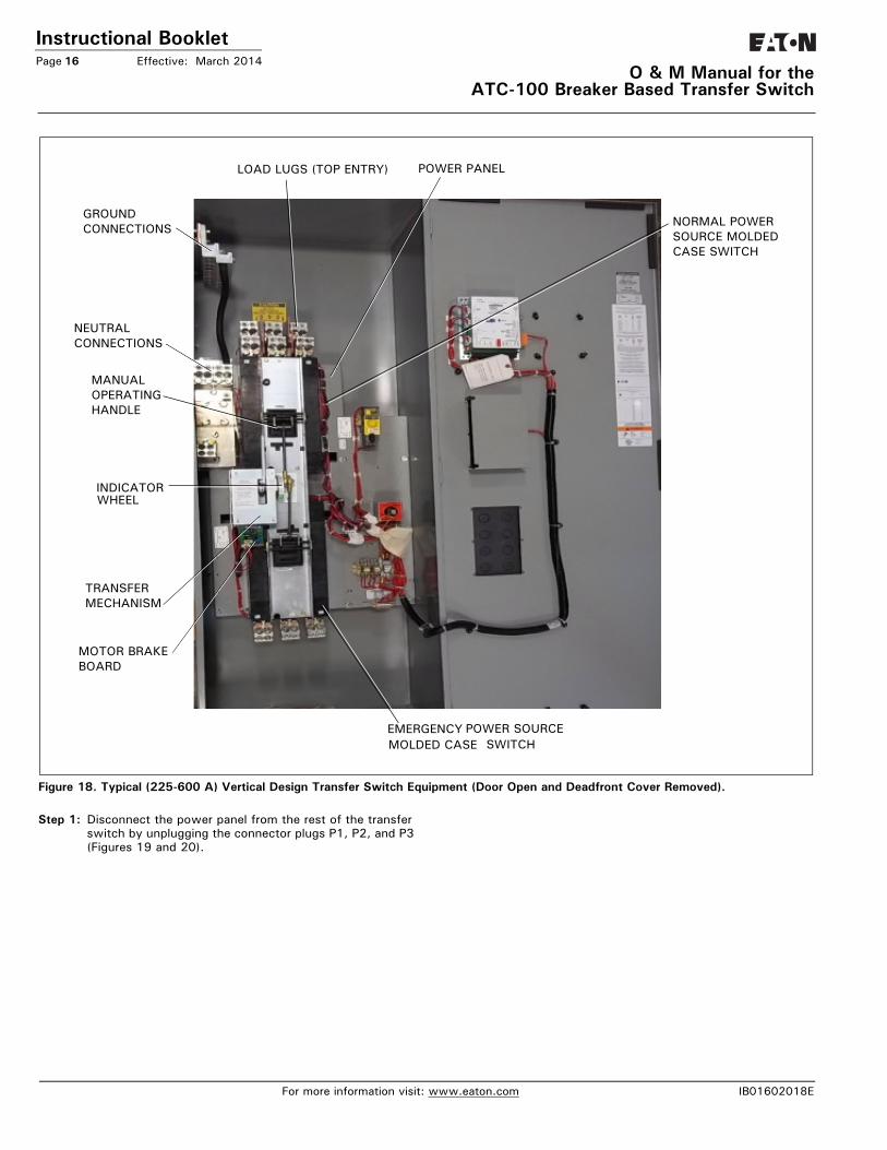
With the solid steel shield removed, proceed with the following steps for bottom feed load termination. Refer to Figure 18 for transfer switch component names and locations.
ATC-300Electrical
asease
Source 1
Source 2
Available
Available
Connected
Connected
Load
Unit Status
Alarm Reset
EngineTest Lamp
Test
Help Step
Enter
Bypass TDNE / TDEN
WARNINGIF THE LOAD LUG LOCATION IS BEING CHANGED ON ALREADY INSTALLED TRANSFER SWITCH EQUIPMENT, MAKE SURE THAT THE UTILITY, GENERATOR, AND OTHER POWER SOURCES CON-NECTED TO THE EQUIPMENT ARE DE-ENERGIZED. HAZARDOUS VOLTAGES ARE PRESENT INSIDE ATS EQUIPMENT THAT CAN CAUSE SEVERE PERSONAL INJURY OR DEATH.
IB01602018E For more information visit: www.eaton.com
Instructional BookletPage 16 Effective: March 2014
O & M Manual for theATC-100 Breaker Based Transfer Switch
Figure 18. Typical (225-600 A) Vertical Design Transfer Switch Equipment (Door Open and Deadfront Cover Removed).
Step 1: Disconnect the power panel from the rest of the transfer switch by unplugging the connector plugs P1, P2, and P3 (Figures 19 and 20).
NORMAL POWERSOURCE MOLDEDCASE SWITCH
GROUNDCONNECTIONS
MANUAL OPERATINGHANDLE
INDICATORWHEEL
TRANSFERMECHANISM
MOTOR BRAKEBOARD
EMERGENCY POWER SOURCEMOLDED CASE SWITCH
NEUTRALCONNECTIONS
LOAD LUGS (TOP ENTRY) POWER PANEL
For more information visit: www.eaton.com IB01602018E

IB
Instructional BookletEffective: March 2014 Page 17
O & M Manual for the ATC-100 Breaker Based Transfer Switch
Figure 19. Location of the P1, P2, and P3 Connector Plugs for ATSs with the North American Market Transformer Panel.
Figure 20. Location of the P1, P2, and P3 Connector Plugs for ATSs with the International Market Transformer Panel.
Step 2: Remove the bolt that bonds the neutral strap to the rear of the enclosure, if it is in place.
Step 3: Remove the four bolts that secure the power panel in the enclosure. Depending upon the size of the panel, it may be advisable to have assistance with the removal. Once the power panel is free, carefully move it to a solid work surface (Figure 21).
Figure 21. Power Panel Removed from the Enclosure (with the Transfer Mechanism Removed for Clarity - 225-600 A Models).
01602018E For more information visit: www.eaton.com

Instructional BookletPage 18 Effective: March 2014
O & M Manual for theATC-100 Breaker Based Transfer Switch
Figure 22. 4 Pole Neutral Bond for Service Entrance
Step 4: Remove the operating mechanism from the front of the power panel by removing the six bolts holding the mecha-nism in position. The molded case switches or optional circuit breakers should not be removed (Figure 23).
NEUTRALASSEMBLY
GROUNDCONNECTION
NEUTRAL BOND(FOR SERVICE ENTRANCE)
NEUTRAL TONEUTRALASSEMBLYJUMPER
NOTICEAT THIS POINT, TAKE THE TIME TO REFER TO FIGURE18 AND BECOME FAMILIAR WITH THE INSIDE REAR OF THE ENCLOSURE AND THE POWER PANEL MOUNTING PROVISIONS AVAILABLE FOR BOTH TOP AND BOTTOM ENTRY. IT WILL FACILITATE REINSTAL-LATION OF THE POWER PANEL.
NOTICETHE REAR-MOUNTED LOAD LUGS, DIP-INSULATED BUS BARS, STANDOFF INSULATORS, GLASS POLYESTER PHASE BARRIERS, AND METAL MOUNTING BRACKET ARE DESIGNED TO BE REMOVED AS ONE LOAD LUG ASSEMBLY (FIGURE 23).
For more information visit: www.eaton.com IB01602018E

Instructional BookletEffective: March 2014 Page 19
O & M Manual for the ATC-100 Breaker Based Transfer Switch
Figure 23. Mounted Load Lug Assembly (225-600 A Models).
Step 5: The load lug assembly is removed by first removing the four, six, or eight bolts securing the pieces of insulated bus to the back of the power panel. The number of mounting bolts depends upon whether 2-, 3-, or 4-pole devices are installed. Mounting bolts are accessed through holes in the load end of the molded case switches or optional circuit breakers.
Step 6: Remove the four bolts holding the mounting bracket to the upper rear portion of the power panel. The load lug assembly can now be removed as one unit. Note that there are grooves in the back of the power panel and in the mounting bracket that keep the polyester phase barri-ers in their proper positions.
Step 7: Turn the load lug assembly 180° with the lugs at the bot-tom and remount the assembly by reversing the proce-dures described in Steps 5 and 6. The mounting bracket will now be bolted to the bottom of the power panel. Make certain that all glass polyester phase barriers are in place and positioned properly in the grooves. When mak-ing any bolted connection to the bus, comply with the torque requirements as outlined in Table 4.
Table 4. Bolted Bus Connection Torque Requirements.
Step 8: Remount the operating mechanism to the front of the power panel with the six bolts removed previously in Step 4.
Step 9: Position the power panel in the enclosure such that the two upper elongated holes, one on either side of the power panel, fit over the two positioning bolts located in the rear of the enclosure. This will line up the four correct mounting holes in the power panel with the pre-tapped inserts in the rear of the enclosure.
Step 10: With the power panel held securely against the back of the enclosure, replace and tighten the four mounting bolts removed previously in Step 3.
Step 11: If applicable, attach the neutral strap, removed in Step 2, to the back of the enclosure through the upper bond-ing hole.
Step 12: Reconnect the P1, P2, and P3 connector plugs that were disconnected in Step 1.
4.5 Power Cable Connections
POWER PANELSWITCHING DEVICE
TORQUEFT-LB (NM)
Type FD 10 (14)
Type KD 20 (27)
Type LD 25 (34)
WARNINGPOWER CONDUCTORS MAY HAVE VOLTAGE PRESENT THAT CAN CAUSE SEVERE PERSONAL INJURY OR DEATH. DE-ENERGIZE ALL POWER OR CONTROL CIRCUIT CONDUCTORS TO BE CONNECTED TO THE ATS EQUIPMENT BEFORE BEGINNING TO WORK WITH THE CONDUCTORS AND/OR TERMINATING THEM TO THE EQUIPMENT.
CAUTIONUSE OF CABLE LUGS NOT DESIGNED FOR THE ATS MAY CAUSE HEATING PROBLEMS. BREAKER LUGS ONLY MOUNT TO THE BREAKER, WHILE TRANSFER SWITCH LUGS MOUNT TO BOTH THE BREAKER AND THE BUS BAR BEHIND THE BREAKER. FOR INSTAL-LATION INSTRUCTIONS, REFER TO THE INSTRUCTION LEAFLET SUPPLIED FOR THE SPECIFIC LUGS.
IB01602018E For more information visit: www.eaton.com

Instructional BookletPage 20 Effective: March 2014
O & M Manual for theATC-100 Breaker Based Transfer Switch
Test all power cables prior to connection to the unit to ensure that the conductors or cable insulation have not been damaged while being pulled into position.
Power cables are to be connected to solderless screw type lugs located on the ATS switching devices. Refer to the separate Cus-tomer Wiring Booklet supplied with the ATS equipment for power termination. Verify that the lugs supplied will accommodate the power cables being used. Also verify that the cables comply with local electrical codes. Standard ATS equipment, as supplied from the factory, will accommodate the wire sizes shown in Table 5.
Carefully strip the insulation from the power cables to avoid nick-ing or ringing of the conductor strands. Prepare the stripped con-ductor termination end by cleaning it with a wire brush. If aluminum conductors are used, apply an appropriate joint com-pound to the clean conductor surface area.
Tighten the cable lugs to the torque identified on the label affixed to the door of the unit.
Table 5. Transfer Switch Equipment Wire Sizes
4.6 Wiring
Power sources, load conductors, and control wiring should be connected to locations as indicated in the Customer Wiring Book-let supplied with the ATS equipment.
Once the ATS equipment has been installed and wired, perform the initial mechanical and electrical procedures as outlined in Sec-tion 6 to verify that the equipment is installed and operating prop-erly.
CAUTIONTO HELP PREVENT COMPONENT DAMAGE OR FUTURE MALFUNC-TIONS, USE EXTREME CARE TO KEEP CONTAMINANTS OUT OF THE ATS EQUIPMENT WHEN MAKING POWER CABLE CONNEC-TIONS.
CAUTIONRUN THE POWER CABLE THROUGH THE GUTTER SPACE PROVIDED TO THE RIGHT OF POWER PANEL. DO NOT ROUTE THE POWER CABLES BEHIND OR TO THE LEFT OF THE POWER PANEL. RUNNING THE CABLES BEHIND OR TO THE LEFT OF THE POWER PANEL COULD INTERFERE WITH THE PROPER OPERATION OF THE TRANS-FER SWITCH.
WARNINGIMPROPER POWER CABLE CONNECTIONS CAN CAUSE EXCESSIVE HEAT AND SUBSEQUENT EQUIPMENT FAILURE.
WARNINGPOWER CONDUCTORS AND CONTROL WIRING MAY HAVE VOLT-AGE PRESENT THAT CAN CAUSE SEVERE PERSONAL INJURY OR DEATH. DEENERGIZE ALL POWER OR CONTROL CIRCUIT CONDUC-TORS BEFORE BEGINNING TO PERFORM ANY WIRING ACTIVITY TO OR WITHIN THE ATS EQUIPMENT.
CAUTIONENSURE THE ATS VOLTAGE IS SET CORRECTLY. IT SHOULD BE THE SAME AS THE UTILITY AND GENERATOR LINE VOLTAGES. OPERATING THE EQUIPMENT ON IMPROPER VOLTAGE CAN CAUSE EQUIPMENT DAMAGE.
NOTICEREMEMBER TO REATTACH THE SOLID STEEL POWER PANEL SHIELD TO THE RATCHET ASSEMBLY AFTER COMPLETING ANY OF THE PROCEDURES DESCRIBED IN THIS SECTION.
TRANSFER SWITCH AMPERE RATING WIRE SIZE RANGES NUMBER OF CABLES PER PHASE TERMINAL TEMPERATURE RATING °C (°F)
30-100 #14-3/0 1 75 (167)
150 #6-300KCMIL 1 75 (167)
225-300 #3-350KCMIL 1 75 (167)
400 #3-350KCMIL 2 75 (167)
600 (3P) #1-500KCMIL 2 75 (167)
For more information visit: www.eaton.com IB01602018E
Instructional BookletEffective: March 2014 Page 21
O & M Manual for the ATC-100 Breaker Based Transfer Switch
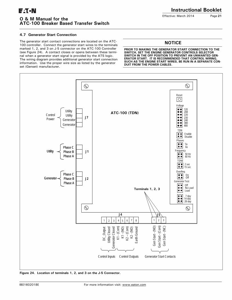
4.7 Generator Start Connection
The generator start contact connections are located on the ATC-100 controller. Connect the generator start wires to the terminals marked 1, 2, and 3 on J-5 connector on the ATC-100 Controller (see Figure 24). A contact closes or opens between these termi-nal when a generator start signal is provided by the ATS logic. The wiring diagram provides additional generator start connection information. Use the proper wire size as listed by the generator set (Genset) manufacturer.
Figure 24. Location of terminals 1, 2, and 3 on the J-5 Connector.
NOTICEPRIOR TO MAKING THE GENERATOR START CONNECTION TO THE SWITCH, SET THE ENGINE GENERATOR CONTROLS SELECTOR SWITCH IN THE OFF POSITION TO PREVENT AN UNWANTED GEN-ERATOR START. IT IS RECOMMENDED THAT CONTROL WIRING, SUCH AS THE ENGINE START WIRES, BE RUN IN A SEPARATE CON-DUIT FROM THE POWER CABLES.
1 2 3 4 5 6 7 8 1 2
J4
J7
J2
J1
J5
Phase CPhase BPhase A
UtilityPhase CPhase BPhase A
Utility
Phase CPhase BPhase A
GeneratorPhase CPhase BPhase A
Generator
UtilityUtility
GeneratorControlPower
Generator
K1 -
(Com
)K1
-(N
O)
DC_O
utput
Gene
rator
Clos
ed
K2 –
(Com
)K2
-(N
O)Ea
rth G
roun
d
Gen S
tart -
(Com
)Ge
n Star
t -(N
O)
Control Inputs
Utilit
y Clos
ed
Control Outputs
3
Gen S
tart -
(NC)
Generator Start Contacts
Reset
120208220230240380480
Voltage
1φ3φ
Phases
50 Hz60 Hz
Frequency
2 sec15 sec
TDNE
OnOff
Overfreq
OffNo LoadLoad
Generator Test
7 day14 day28 day
EnableDisable
TDN
Terminals 1, 2, 3
ATC-100 (TDN)
IB01602018E For more information visit: www.eaton.com

Instructional BookletPage 22 Effective: March 2014
O & M Manual for theATC-100 Breaker Based Transfer Switch
4.8 Voltage Selection Adjustments
Certain devices, such as the Voltage Selection Panel, sensing relays, and timers, need to be set and/or calibrated prior to placing the ATS equipment in service. Adjustments for logic devices are described in the separate instructional document dedicated to the specific logic being used. Voltage selection adjustments are described in this section.
4.8.1 North American Market Voltage Selection Panels (120, 208, 240, 480, and 600 V, - 60 Hz)
Vertical and Horizontal Design Voltage Selection
The North American market Voltage Selection Panel consists of multi-tap transformers, contained in a steel case mounted in the enclosure. The cover has “teardrop” holes for the screws to allow easy access to the transformers. To change the voltage from the factory default 600 Vac, follow the steps detailed below.
Step1: Loosen the four screws securing the cover of the Voltage Selection Transformer case. Slide the cover up, then away from the case.
Step 2: Remove the wires from the primary taps of both trans-formers and installed them on the taps for the desired voltage (Figure 25). Note that only one wire per trans-former is moved since the second wire is the zero refer-ence.
Figure 25. North American Market Voltage Selection Panel with Voltage Being Selected.
Step 3: Reinstall the cover and tighten the four screws.
4.9 Preliminary ChecksAfter the ATS enclosure is installed and power cables are con-nected to the equipment, thoroughly inspect the unit to ensure that no tools were left inside and that the cabinet is free of debris. If necessary, use a vacuum cleaner to remove any and all con-struction or installation debris from the equipment.
Read and understand all labels on the equipment. Review and understand the wiring diagrams supplied with the equipment. Note any optional accessories that may have been furnished with this unit and review their operation.
Verify that the phase-to-phase line voltages of both the utility and generator power sources are the same and that they match the rated voltage as indicated on the ATS ratings label.
CAUTIONBE SURE THAT THE CORRECT VOLTAGE IS SELECTED TO MATCH THE SYSTEM VOLTAGE. AN IMPROPER SELECTION AND/OR CON-NECTION COULD RESULT IN EQUIPMENT DAMAGE.
CAUTIONWHEN CHANGING THE VOLTAGE, ONE WIRE MUST BE MOVED ON THE PRIMARY TAPS OF BOTH TRANSFORMERS.
CAUTIONSEVERE EQUIPMENT DAMAGE CAN RESULT IF THE UNIT IS NOT APPLIED AT PROPER VOLTAGE. DO NOT ENERGIZE THE EQUIP-MENT IF THE SUPPLY VOLTAGES DO NOT MATCH EQUIPMENT RATINGS LABEL.
For more information visit: www.eaton.com IB01602018E

Instructional BookletEffective: March 2014 Page 23
O & M Manual for the ATC-100 Breaker Based Transfer Switch
4.10 Terminal Block Wire Installation and Removal
Proceed with the following steps and associated figures to install or remove terminal block wiring.
Step 1: Figure 26 shows two tension clamp terminal blocks. There is a large one and small one, but the operation is the same for both. A small tool, such as a screwdriver, will be pushed into the square hole next to the wire hole and a wire will be inserted into the larger circular hole on the outer edge.
Figure 26. Tension Clamp Terminal Blocks.
Step 2: Begin by inserting a small, flathead screwdriver into the square (tool) hole with the flat surface of the screwdriver against the back wall of the hole (see Figure 27). With a little bit of force, push the screwdriver in on a slight angle toward the center of the clamp. Be sure to slide it in until it clicks. You will then see the clamp open in the wire hole.
Figure 27. Screwdriver Inserted in the “Tool” Hole.
Step 3: Once the screwdriver is in place, obtain a stripped wire (strip about 1/4 in.) and insert it into the larger circular wire hole. Push the wire in until it can go no further (see Figure 28).
Figure 28. Wire Inserted in the “Wire” Hole.
TOOL HOLE WIRE HOLE
IB01602018E For more information visit: www.eaton.com

Instructional BookletPage 24 Effective: March 2014
O & M Manual for theATC-100 Breaker Based Transfer Switch
Section 5: Operation5.1 General
An ATS provides main contacts to connect and disconnect the load to and from the Utility and Generator power sources (Section 3.2.2). Each transfer mechanism provides the mechanical motion required to open and close the mechanically interlocked main con-tacts (Section 3.2.3).
Note that the transfer mechanisms for the two types of ATSs described in this booklet (30-150 A and 225-600 A) are different for both the manual and automatic modes.
IF AN ATS WITH ANY TYPE OF ELECTRICAL OPERATING CAPABILI-TIES IS TO BE OPERATED UTILIZING THE MANUAL OPERATING HAN-DLE, IT IS STRONGLY RECOMMENDED THAT THE TRANSFER MOTOR CIRCUIT FIRST BE ISOLATED. THIS IS ACCOMPLISHED BY UNPLUG-GING THE (P3) PLUG MARKED MOTOR DISCONNECT (FIGURE 31). ANY ATTEMPT TO USE THE MANUAL OPERATING HANDLE WITHOUT FIRST ISOLATING THE MOTOR CIRCUIT CAUSES AN AUTOMATIC TRANSFER.
Figure 29. Motor Disconnect P3 must be disconnected.
5.2 Manual Operation (225-600 A)
The manual operating handle can be used to create the rotational motion required to open and close the main contacts through a rigid mechanical interlocking system (Figure 30). An indicator wheel attached to the operating handle and mechanical interlock-ing system rotates with each movement of the handle to open and/or close the main contacts (Figures 30). Three distinct switch positions are provided and indicated visually on the indicator wheel (Figure 32).
Figure 30. ATS Manual Operating Handle in Use (225-600 A Models).
Figure 31. Indicator Wheel Mounted in the Switch with Motor Under the Wheel (225-600 A Models).
NOTICE
For more information visit: www.eaton.com IB01602018E

Instructional BookletEffective: March 2014 Page 25
O & M Manual for the ATC-100 Breaker Based Transfer Switch
Figure 32. Indicator Wheel in Neutral Position (225-600 A Models).
The three distinct switch positions or contact conditions are:
Utility: The contacts associated with the Utility power source are closed and the Generator power source contacts are open.
Neutral: The contacts associated with both the Utility and Gen-erator power sources are open. This position allows for load circuit maintenance.
Generator:The contacts associated with the Utility power source are open and the Generator power source contacts are closed.
To manually operate the ATS, the manual operating handle is ratcheted until the desired switch position is indicated on the indi-cator wheel. The operating handle, no matter what design or type of switch operation, is always electrically "dead" and the indicator wheel free-wheels should a particular switch have a motor and be capable of electrical operation. This feature ensures no operator problems should the switch automatically operate while the man-ual handle is being used.
5.3 Manual Operation (30 - 150 A)
To operate the breaker manually, or if the breaker trips, unplug P3 from S3 to disconnect the motor circuit (Figure 33). Turn and hold the break release lever to “HOLD FOR MANUAL OPERA-TION” position, and then rotate the manual operator knob in either direction to move the ATS into the desired position. Let go of the brake release lever for “AUTOMATIC OPERATION” after P3 and S3 are reconnected.
Figure 33. Switch Being Manually Operated (30-150 A Model).
5.4 Automatic Transfer
The operating sequence of an ATS is dictated by the switch's standard features and selected options. Operation of an ATS dur-ing Utility power source failure and Utility power source restora-tion will be described here with only standard options included on the switch. Additional options, as described in Section 3, can change sequences and timing, depending upon the options selected. It is strongly suggested that you become familiar with additional options selected with the particular ATS and their effect on the normal operation of an ATS.
5.4.1 Utility Power Source Failure
Standard Utility power source failure is defined as a reduction or loss of voltage. If this occurs, the sequence of operation is as fol-lows.
1. Failure of Utility is detected by the controller intelligence.
2. When the controller detects a failure, the engine contacts close or open (after delay if programmed) and start the engine-driven generator.
3. When the Generator voltage reaches its operation rating, the K2 relay closes, starting the transfer operation. This operat-ing sequence opens the Utility switch and closes the Genera-tor switch.
4. The load is now transferred to the Generator power source.
5.4.2 Utility Power Source Restoration1. A return to the Utility power source begins when the voltage
in all phases of a three-phase sensing unit, or phase-to-phase in a single sensing unit, is restored to a preset value.
2. At the present voltage, the controller will cause the K1 relay to change state. This starts the return to the Utility power source and Utility transfer switch operation.
3. During this sequence, the Generator power source switch is opened and the Utility power source switch is closed.
4. Simultaneously, the engine cool-down timer initiates the shut down of the engine driven generator.
Transfer of the load back to the Utility power source is now com-plete.
IB01602018E For more information visit: www.eaton.com

Instructional BookletPage 26 Effective: March 2014
O & M Manual for theATC-100 Breaker Based Transfer Switch
Section 6: Testing and Problem Solving6.1 Testing
After the ATS equipment is initially installed or during planned out-ages, the installation should be tested to ensure that all equipment operates properly. This attention to detail will help avoid unex-pected malfunctions. Mechanical and/or electrical tests should be performed as described in this section.
The frequency of subsequent testing should be based on recom-mendations of the Genset manufacturer. Use the system test pushbutton to check the electrical operation of the switch.
6.1.1 Mechanical and/or Electrical Testing
Energize the ATS equipment as described in Sections 6.1.2 through 6.1.6. Insure that all safety precautions are taken and that all WARNINGS and CAUTIONS are observed.
6.1.2 No Voltage Steps
With no voltage available on either power source, proceed as fol-lows.
Step 1: Check to make sure that both the Utility and Generator power switching devices are in the OPEN position. The switching devices can be put into the OPEN position using of the manual operating handle, stopping in the NEUTRAL position.
Step 2: The generator engine start controls should be in the OFF position to prevent an undesired start.
Step 3: Ensure that the ATS has been set to the proper applied system voltage (See Section 4.8).
Step 4: Check all ATS loads to ensure that they are ready to be energized.
6.1.3 Connecting the Power Sources
Step 1: Close the Utility power source upstream protection device. The Utility power switching device should close.
Step 2: Connect the engine start battery cable.
Step 3: With the emergency generator in the OFF position, close the Generator power source upstream protective device, assuming such a device used.
AT THIS POINT, AND PRIOR TO MAKING ANY ATTEMPT TO ENERGIZE THE ATS EQUIPMENT, THE ENGINE-DRIVEN GENERATOR SHOULD BE OPERATED. IF NECESSARY, THE VOLTAGE REGULATOR ON THE GENERATOR SHOULD BE ADJUSTED ACCORDING TO THE MANU-FACTURER’S RECOMMENDATIONS. THE ATS EQUIPMENT WILL RESPOND ONLY TO THE RATED VOLTAGE AND FREQUENCY PRO-GRAMMED INTO THE CONTROLLER.
Step 4: Close any generator engine-start controls opened as a result of actions taken in Step 1, Section 6.1.2.
Step 5: Where required, use an accurate voltmeter to check phase-to-phase and phase-to-neutral voltages present at the transfer switch Utility, Generator, and/or load termi-nals.
6.1.4 Operational Checks
Step 1: Check to ensure that the Utility switching device is in the CLOSED position. This should have been done in Section 6.1.3, Step 1.
Step 2: Initiate an automatic transfer operation from the Utility to the Generator power source by pressing the <System Test> pushbuttons (Engine start and set generator test) two times.
a. After the Time Delay Engine Starting (TDES) has timed out, the engine should start, run, and build up to normal voltage and frequency.
b. The transfer switch will transfer to the Generator power source (the Utility switching device opens and Generator switching device closes) after the Time Delay Normal to Emergency (TDNE) times out.
Step 3: Initiate an automatic transfer operation back to the Utility power source by pressing the <System Test> pushbut-tons (Engine start and set generator test) one time.
1. After the Time Delay Emergency to Normal timer (TDEN) has timed out, the transfer switch will transfer back to the Utility power source (the Generator switching device opens and the Utility switching device closes).
2. The Time Delay for Engine Cool-Off (TDEC) will allow the engine to run unloaded for a preset time after transfer to the Utility power source is completed.
6.1.5 Alternate Tests1. Alternate operational tests may be possible depending upon
the options provided with any given ATS. Refer to the sche-matic diagram provided with the ATS equipment, along with the specification nameplate, to determine the exact options provided.
2. If you attempt to manually operate the ATS with the Utility power source connected and available, the ATC-100 logic will cycle the ATS back to the Utility power source since it is the preferred source. The ATS was designed with this safety fea-ture in case a manual transfer is attempted while the switch is in automatic mode and under load.
WARNINGHIGH VOLTAGES ASSOCIATED WITH OPERATIONAL TRANSFER SWITCH EQUIPMENT PRESENT A SHOCK HAZARD THAT CAN CAUSE SEVERE PERSONAL INJURY OR DEATH. USE EXTREME CAUTION TO AVOID TOUCHING ELECTRICAL CONNECTIONS WHENEVER INSPECTING OR TESTING THE EQUIPMENT.
IN ADDITION, IMPROPER OPERATION OF THE GENERATOR SET PRESENTS A HAZARD THAT CAN CAUSE SEVERE PERSONAL INJURY OR DEATH. OBSERVE ALL SAFETY PRECAUTIONS IN YOUR GENERATOR SET OPERATIONS AND INSTALLATION MANUALS.
NOTICESINCE FEATURE 4 (TIME DELAY ENGINE COOL-OFF), AS DESCRIBED IN SECTION 3, IS A STANDARD FEATURE, AN ENGINE START SIG-NAL WILL BE PRESENT FOR A PERIOD OF TIME WHEN THE SWITCH IS FIRST ENERGIZED. THE PERIOD OF TIME IS EQUAL TO THE TIMER SETTING. TO AVOID STARTING THE ENGINE DURING THIS TIME PERIOD, TURN THE GENERATOR CONTROLS TO THE OFF POSITION.
NOTICE
For more information visit: www.eaton.com IB01602018E

Instructional BookletEffective: March 2014 Page 27
O & M Manual for the ATC-100 Breaker Based Transfer Switch
6.2 Problem Solving
HAZARDOUS VOLTAGES IN AND AROUND ATS EQUIPMENT DURING THE PROBLEM SOLVING PROCESS CAN CAUSE SEVERE PERSONAL INJURY AND/OR DEATH. AVOID CONTACT WITH ANY VOLTAGE SOURCE WHILE PROBLEM SOLVING.
ONLY PROPERLY TRAINED PERSONNEL, FAMILIAR WITH THE ATS EQUIPMENT AND ITS ASSOCIATED EQUIPMENT, SHOULD BE PER-MITTED TO PERFORM THE PROBLEM SOLVING FUNCTION. IF AN INDIVIDUAL IS NOT QUALIFIED TO PERFORM THE PROBLEM SOLV-ING FUNCTION, THE INDIVIDUAL SHOULD NOT ATTEMPT ANY OF THESE PROCEDURES.
A basic problem-solving effort is the first step to take prior to call-ing for assistance. Frequently, the effort will successfully address most problems encountered. The problem solving procedure is presented in the Troubleshooting Guide (Table 3, Section 5 of ATC-100 Controller Instruction Booklet IB01602019E). Remem-ber, only qualified individuals familiar with the ATS equipment and the system in which it is applied should attempt these problem solving procedures.
If a problem persists after having completed the problem solving procedure, contact a Eaton representative for further assistance. When calling for assistance, the following is the minimum infor-mation required to properly address the need:
1. Style number of ATS, if applicable;
2. Catalog number of ATS;
3. Actual location of the ATS (type of facility, address, etc.);
4. Company name and name and position of individual repre-senting company;
5. Basic description of the situation as it exists; and
6. Any results of the problem solving steps taken and/or read-ings taken.
Section 7: Adjustments7.1 General
Refer to I.B.01602019, supplied with the ATS for ATC-100 Con-troller adjustments and programming.
WARNING
WARNING
IB01602018E For more information visit: www.eaton.com

Instructional BookletPage 28 Effective: March 2014
O & M Manual for theATC-100 Breaker Based Transfer Switch
Section 8: Maintenance8.1 Introduction
In general, ATS switch equipment is designed to be relatively maintenance free under normal usage. However, because of the variability of application conditions and the importance placed on dependable operation by this type of equipment, inspection and maintenance checks should be made on a regularly scheduled basis. Since equipment maintenance will consist mainly of keep-ing the equipment clean, the frequency of maintenance will depend to a large extent on the cleanliness of the equipment’s sur-roundings. If a significant amount of dust or foreign matter is present, a more frequent maintenance schedule should be fol-lowed.
It is suggested that visual inspections of the equipment be made on a regular basis, not just during scheduled periods. Always be alert for an accumulation of dirt in and around the structure; loose parts; and/or hardware, cracks, and/or discoloration to insulation; and damaged or discolored components.
8.2 Procedures
A suggested maintenance procedure is outlined in Table 6.
Table 6. Periodic Maintenance Procedures
WARNINGHIGH VOLTAGES ARE PRESENT IN AND AROUND ATS EQUIPMENT. BEFORE INSPECTING OR MAINTAINING THIS EQUIPMENT, DISCON-NECT THE LINE POWER FROM, THEN LOCK OUT, IF POSSIBLE, THE NEXT HIGHEST DISCONNECT DEVICE. FAILURE TO FOLLOW THIS PROCEDURE COULD CAUSE SEVERE PERSONAL INJURY AND/OR DEATH.
STEP ACTION
a.Make the ATS equipment safe for inspection and/or maintenance. Disconnect the line power from equipment being serviced by opening the next highest disconnect device. Make certain that any accessory control power is switched off by disconnecting all con-trol plugs.
b.Inspect the structure area for safety hazards or potential maintenance problems. Inspect the area, especially where molded case switching devices are installed, for any safety hazards, including personnel safety and fire hazards. Exposure to certain chemical vapors can cause deterioration of electrical connections.
Inspect for accumulated dirt, loose hardware, or physical damage.
Examine the primary insulation for evidence of cracking or overheating. Overheating will show as discoloration, melting, or blistering of conductor insulation, or as pitting or melting of conductor surfaces due to arcing.
Inspect the secondary control connections for damage and the control wiring for insulation integ-rity.
c.Inspect the molded case switching devices for dust, dirt, soot, grease, moisture, or corrosion. Remove dust, dirt, soot, grease, moisture, and corrosion contamination from the surface of the switching device using a dry soft lint-free cloth, dry soft bristle brush, and vacuum cleaner. Do not blow debris into the circuit breaker or nearby breaker structure. If contamination is found, look for the source and fix the problem.
d.Check for material integrity, uneven wear, discoloration, or loose hardware. Severe material cracking will require replacement and loose hardware will need to be tightened.
e.Check the terminals and connectors for looseness or signs of overheating. Overheating will show as discoloration, melting, or blistering of the conductor insulation.
Connections that do not have signs of looseness or overheating should not be disturbed.
f. Exercise the molded case switching devices if they are not often exercised while in operation.This will permit a “wiping” action by the contacts.
If a switching device is used for frequent switching during normal operation, this step can be dis-regarded.
g.Return the ATS equipment to service. Make certain all barriers are in place and doors closed. Reapply secondary and primary power.
For more information visit: www.eaton.com IB01602018E

Instructional BookletEffective: March 2014 Page 29
O & M Manual for the ATC-100 Breaker Based Transfer Switch
Section 9: Renewal Parts Guide9.1 General
Refer to Figure 34 and 35 for assistance with selecting and order-ing selected ATS renewal parts. For more information please see Renewal Parts Publication (RP01603002E)
Example: To order the transformer panel for an ATV1KDA30300XRU transfer switch, order Catalog Number as shown in Figures 34 and 35.
Figure 34. Typical ATC-100 Controlled Breaker Type ATS.
REQUIRED TO COMPLETE THE
COMPLETE POWER PANEL - PLEASE NOTE THE ORIGINALCATALOG NUMBER OF TRANSFER SWITCH, AS IT IS
CATALOG NUMBER OF A POWER PANEL.
EXAMPLE: ATV1KDA30300XRUATH1FDA20100WRU
VERTICAL POWER PANEL CAT#: PPV1KDA30300XKU
NOTE THAT THE SECOND TO THE LAST CHARACTER WILL ALWAYS BE A “K” WHEN ORDERING A REPLACEMENTPOWER PANEL.
HORIZONTAL POWER PANEL CAT#: PPH1FDA20100WKU
CAT#: 5715B82G06
(NOT SHOWN)
CAT#: 8885C45G36 (Vertical Mech.)8885C45G37 (Horizontal Mech.)
MOTOR BRAKE BOARD ASSEMBLY
DOMESTIC VOLTAGE TRANSFORMER PANEL
IB01602018E For more information visit: www.eaton.com

Instructional BookletPage 30 Effective: March 2014
O & M Manual for theATC-100 Breaker Based Transfer Switch
Figure 35. Typical ATC-100 Controlled Breaker Type ATS.
WIRE HARNESS
TRANSFORMERPANEL (VERTICALMOUNT SHOWN)
DOMESTICVOLTAGETRANSFORMERPANEL
8885C45G36
ATC-100 CONTROLLER-TDN (CAT#: 8160A00G23)
CAT#: 5724B93G02 (Domestic)CAT#: 5724B93G03 (AG-Long)CAT#: 5724B93G04 (AG-Short)
(Vertical Mech.)
8885C45G37(Horizontal Mech.)
CAT#:
For more information visit: www.eaton.com IB01602018E

Instructional BookletEffective: March 2014 Page 31
O & M Manual for the ATC-100 Breaker Based Transfer Switch
Section 10: ATC-100 Controlled ATS Quick Start Instructions
Step 1: Mount the ATS on a flat rigid surface (Figure 36). Shim if necessary. For seismic mounting requirements, check the main instruction sections of this manual.
Figure 36. Mounting Details.
Step 2: Install the power cables. Cables must be sized and installed per National Electrical Code, refer to NFPA70. The cables must be sized within the specified cable size range on the side of the cable connectors.
Connect the cables and torque to the correct value indicated on the label near the lugs in the following order:
1. Load Cables* (T1, T2, T3);
2. Utility or Utility Supply (N1, N2, N3); and
3. Generator or Generator Supply (E1, E2, E3).
For 4 pole transfer switches, connect the load cables (TN), Utility or utility supply (NN), and Generator or generator supply (EN). Refer to Figures 37 and 38 for the location of all parts discussed in this document.
* Load cables on switches using the vertical design MUST be connected and torqued BEFORE installing the SUPPLY cables (Figure 37).
WARNINGTHESE QUICK START INSTRUCTIONS ARE NOT A COMPLETE SOURCE OF INFORMATION ON THE ATC-100 CONTROLLED ATS EQUIPMENT. INSTALLATION SHOULD NOT BE STARTED UNTIL THE ENTIRE INSTRUCTION BOOK HAS BEEN REVIEWED AND UNDER-STOOD. FAILURE TO FOLLOW THE FULL INSTRUCTIONS CAN RESULT IN DEATH, SEVERE PERSONAL INJURY, OR PROPERTY DAMAGE.
WARNINGTHESE QUICK START INSTRUCTIONS ARE PROVIDED FOR USE ONLY BY TECHNICIANS HIGHLY FAMILIAR AND EXPERIENCED WITH ATC-100 CONTROLLED ATS EQUIPMENT INSTALLATION, SET UP, AND TESTING. IT IS STRONGLY SUGGESTED THAT THE FULL INSTRUCTIONS BE FOLLOWED FOR ALL INSTALLATIONS, SET UP, AND TESTING.
IB01602018E For more information visit: www.eaton.com

Instructional BookletPage 32 Effective: March 2014
O & M Manual for theATC-100 Breaker Based Transfer Switch
Figure 37. 100 A, 3-Pole, ATS Interior Components.
(TOP ENTRY)
NEUTRAL CONNTECTIONS
MANUALOPERATINGHANDLE
INDICATORWHEEL
TRANSFERMECHANISM
MOTORBRAKEBOARD
EMERGENCY POWER SOURCEMOLDED CASE SWITCH
VOLTAGESELECTIONPANEL(DOMESTIC)
NORMALPOWERSOURCEMOLDEDCASE SWITCH
POWER PANEL
LOAD LUG
TRANSFORMERPANEL (VERTICALMOUNT SHOWN)
For more information visit: www.eaton.com IB01602018E

Instructional BookletEffective: March 2014 Page 33
O & M Manual for the ATC-100 Breaker Based Transfer Switch
Figure 38. Horizontal Power Panel.
Step 3: Turn the generator OFF at the generator control panel. This will prevent unexpected activation of the generator.
Step 4: Connect the Engine Generator Start wires to terminals 1 and 2 or 2 and 3 on the J-5 connector on the ATC-100 Controller (Figure 39). This contact is CLOSED (when the controller sends the command for the engine to start. N. O. becomes N. C. and N. C. becomes N. O.. The cus-tomer chooses the appropriate contact for their engine start circuit.) whenever the engine generator is needed, and should be connected to a generator controller. NEVER connect directly to a starter solenoid or ignition system. See the Genset manufacturer instruction leaflet for recommended wire sizes and location procedures.
Step 5: Apply Utility power. If the switch is properly applied for the system voltage ordered, the Utility Available white LED should light (Figure 40). Using a voltmeter, check for proper system voltage on Utility and load terminals. Check all phases on a 3-phase switch. Voltage measure-ments should be taken phase to phase and phase to neu-tral.
LOAD LUG(BOTTOM ENTRY))
IB01602018E For more information visit: www.eaton.com

Instructional BookletPage 34 Effective: March 2014
O & M Manual for theATC-100 Breaker Based Transfer Switch
Figure 39. Generator Start Connection.
1 2 3 4 5 6 7 8 1 2
J4
J7
J2
J1
J5
Phase CPhase BPhase A
UtilityPhase CPhase BPhase A
Utility
Phase CPhase BPhase A
GeneratorPhase CPhase BPhase A
Generator
UtilityUtility
GeneratorControlPower
Generator
K1 -
(Com
)K1
-(N
O)
DC_O
utput
Gene
rator
Clos
ed
K2 –
(Com
)K2
-(N
O)Ea
rth G
roun
d
Gen S
tart -
(Com
)Ge
n Star
t -(N
O)
Control Inputs
Utilit
y Clos
ed
Control Outputs
3
Gen S
tart -
(NC)
Generator Start Contacts
Reset
120208220230240380480
Voltage
1φ3φ
Phases
50 Hz60 Hz
Frequency
2 sec15 sec
TDNE
OnOff
Overfreq
OffNo LoadLoad
Generator Test
7 day14 day28 day
EnableDisable
TDN
Terminals 1, 2, 3
ATC-100 (TDN)
For more information visit: www.eaton.com IB01602018E

Instructional BookletEffective: March 2014 Page 35
O & M Manual for the ATC-100 Breaker Based Transfer Switch
Figure 40. ATC-100 Logic (Utility Supplying Load).
IB01602018E For more information visit: www.eaton.com

Instructional BookletPage 36 Effective: March 2014
O & M Manual for theATC-100 Breaker Based Transfer Switch
Figure 41. Utility - Generator Transfer Switch.
Utility is available
Is Generator available?
Close Generator breaker (Momentarily energize K2)
N
Close Utility switching device (Momentarily energize K1)
Utility becomes unavailable(or System Test, Generator Test)
TDES timer times out
Send “generator start” signal (Energize Gen Start relay)
TDNE timer times out
Open Utility breaker (Momentarily energize K2)
Y
Generator is powering the load
TDEN timer times out
Open Generator breaker(Momentarily energize K1)
Close Utility breaker(Momentarily energize K1)
NIs Utility available yet?
Y
Utility is powering the load
Utility is powering the load
TDEC timer times out
Remove “generator start” signal (De-energize Gen Start relay)
TDN timer times out(if enabled)
TDN timer times out(if enabled)
TDN Implementation
For more information visit: www.eaton.com IB01602018E

Instructional BookletEffective: March 2014 Page 37
O & M Manual for the ATC-100 Breaker Based Transfer Switch
Table 7. Adjustable Features and Setpoints
See tables in the appendix for Voltage and Frequency Pickup and Dropout settings.
Step 6: To change a setpoint of an adjustable feature, access the rear of the controller and move the yellow jumped to the desired location.
Figure 42. ATC-100.
Step 7: Manually start the engine generator at the generator con-troller. Check that the generator is running and the Gener-ator Available amber LED is lit. If the LED is lit, shut down the generator and place the Genset controller in the Auto-operating position. If the LED is not lit, the setpoints should be reviewed and the generator checked for proper voltage and frequency output.
Step 8: Initiate a System Test from the front panel of the ATC-100 (Figure 42). This may be done by pressing and hold-ing the “Engine Start” and “Set Generator Test” buttons simultaneously for 5 seconds.
The generator should start, the ATS should transfer and run on the generator for the set test interval, then proceed to a TDEN countdown and return to Utility. While the ATS is connected to Generator, use a voltmeter to check for correct system voltage on the load terminals of the ATS. Check all phases on a 3-phase system. Voltage measurements should be taken phase to phase and phase to neutral. A load test will cause a momentary power out-age during transfer.
SETPOINT FIXED/ADJUSTABLE SETPOINT UNITS DESCRIPTION RANGE FACTORY DEFAULT
TDES Fixed Seconds Time Delay Engine Start 3 seconds 3 seconds
TDNE Jumper-selectable Seconds Time Delay Normal to Emergency 2 or 15 seconds 15 seconds
TDEN Fixed Minutes Time Delay Emergency to Normal 5 minutes 5 minutes
TDEC Fixed Minutes Time Delay Engine Cool-off 1 minute 1 minute
NOM FREQ Jumper-selectable Hertz Nominal Frequency 50 or 60 Hz AS ORDERED
NOM VOLTS Jumper-selectable Volts Nominal Voltage 120, 208, 220, 230, 240, 380, and 480 volts AS ORDERED
S1 UV DROP Fixed Volts Utility Undervoltage Dropout 80% of NOMV 80% of NOMV in volts
S2 UV DROP Fixed Volts Generator Undervoltage Dropout 80% of NOMV 80% of NOMV in volts
S1 UV PICK Fixed Volts Utility Undervoltage Pickup 90% of NOMV 90% of NOMV in volts
S2 UV PICK Fixed Volts Generator Undervoltage Pickup 90% of NOMV 90% of NOMV in volts
S2 UF DROP Fixed Hertz Generator Underfrequency Dropout 90% of NOMF 90% of NOMF in hertz
S2 UF PICK Fixed Hertz Generator Underfrequency Pickup 95% of NOMF 95% of NOMF in hertz
S2 OF DROP Jumper-selectable Hertz Generator Overfrequency Dropout Off or 115% of NOMF Off
S2 OF PICK Jumper-selectable Hertz Generator Overfrequency Pickup Off or 110% of NOMF Off
Generator Test Jumper-selectable Generator Test Programming 7-DAY, 14-DAY or 28 DAY 7-DAY
TEST MODE Jumper-selectable Test Mode OffNo Load, Load
OFF
TER Fixed Minutes Engine run test time 15 minutes 15 minutes
PHASES Jumper-selectable 3-phase or single phase 1 or 3 AS ORDERED
TDEF Fixed Seconds Time Delay Emergency Fail Timer 6 seconds 6 seconds
TDN Jumper-selectable Seconds Time Delay Neutral Disabled (0 seconds) or Enabled (2 seconds) Enabled (2 seconds)
SET
TESTGENERATORTEST
GENERATORCONNECTED
SYSTEMENGINESTART
UNITSTATUS
UTILITYCONNECTED
UTILITYAVAILABLE
GENERATORAVAILABLE
WARNINGTHE GENERATOR SHOULD BE MANUALLY STARTED AND THE OUT-PUT CHECKED AND VERIFIED BEFORE PROCEEDING TO STEP 7 IF IMPROPER VOLTAGE/FREQUENCY IS APPLIED TO THE LOAD, THE ATS MAY BE DAMAGED.
IB01602018E For more information visit: www.eaton.com

Instructional BookletPage 38 Effective: March 2014
O & M Manual for theATC-100 Breaker Based Transfer Switch
Step 9: ATH1/ATV1 Controlled ATS Power Failure Test - Initiate a Load Test by simulating an actual power failure.
1. This should be done by opening the upstream breaker or fused disconnect switch.
2. The generator should start and the ATS should trans-fer to Generator.
3. After transfer, close the upstream breaker, or close the Utility Control Circuit Fused Disconnect. The TDEN timer should begin counting, and, when com-plete, the ATS should transfer to Utility. The TDEC should time out and shut the Generator power unit down.
NOTICEWHILE PERFORMING TESTING, IF AN UNDESIRED OR UNDOCU-MENTED RESULT OCCURS, FIRST CONTACT THE LOCAL GENSET DEALER. IF THE RESULT IS NOT CORRECTED, CONTACT THE EATON POWER QUALITY TECHNICAL SUPPORT CENTER AT 1-800-354-2070
For more information visit: www.eaton.com IB01602018E

Instructional BookletEffective: March 2014 Page 39
O & M Manual for the ATC-100 Breaker Based Transfer Switch
APPENDIX A: Pickup / Dropout TablesUNDERVOLTAGE PICKUP / DROPOUT TABLE
PERCENTAGE VOLTAGE
120 208 220 230 240 380 415 480 600
90 108 187 198 207 216 342 374 432 540 Pickup
80 96 166 176 184 192 304 332 384 480 Dropout
UNDERFREQUENCY PICKUP / DROPOUT TABLE
PERCENTAGE FREQUENCY
50 60
95 48 57 Pickup
90 45 54 Dropout
OVERFREQUENCY PICKUP / DROPOUT TABLE
PERCENTAGE FREQUENCY
50 60
115 58 69 Dropout
110 55 66 Pickup
IB01602018E For more information visit: www.eaton.com

Instructional BookletPage 40 Effective: March 2014
O & M Manual for theATC-100 Breaker Based Transfer Switch
This instruction booklet is published solely for information pur-poses and should not be considered all-inclusive. If further infor-mation is required, you should consult an authorized Eaton sales representative.
The sale of the product shown in this literature is subject to the terms and conditions outlined in appropriate Eaton selling policies or other contractual agreement between the parties. This litera-ture is not intended to and does not enlarge or add to any such contract. The sole source governing the rights and remedies of any purchaser of this equipment is the contract between the pur-chaser and Eaton.
NO WARRANTIES, EXPRESSED OR IMPLIED, INCLUDING WAR-RANTIES OF FITNESS FOR A PARTICULAR PURPOSE OR MER-CHANTABILITY, OR WARRANTIES ARISING FROM COURSE OF DEALING OR USAGE OF TRADE, ARE MADE REGARDING THE INFORMATION, RECOMMENDATIONS, AND DESCRIPTIONS CONTAINED HEREIN. In no event will Eaton be responsible to the purchaser or user in contract, in tort (including negligence), strict liability or otherwise for any special, indirect, incidental or conse-quential damage or loss whatsoever, including but not limited to damage or loss of use of equipment, plant or power system, cost of capital, loss of power, additional expenses in the use of exist-ing power facilities, or claims against the purchaser or user by its customers resulting from the use of the information, recommen-dations and description contained herein.
CSA is a registered trademark of the Canadian Standards Associa-tion. National Electrical Code and NEC are registered trademarks of the National Fire Protection Association, Quincy, Mass. NEMA is the registered trademark and service mark of the National Elec-trical Manufacturers Association. Uniform Building Code (UBC) is a trademark of the International Conference of Building Officials (ICBO). UL is a federally registered trademark of Underwriters Lab-oratories Inc.
© 2014 Eaton CorporationAll Rights ReservedPrinted in USAPublication No. IB01602018E/TBG00216March 2014
Eaton Electrical Sector1000 Eaton BoulevardCleveland, OH 44122United States877-ETN CARE (877-386-2273)Eaton.com