nxw reversible chiller insta - waterfurnace · preventive maintenance nxw reversible chiller...
TRANSCRIPT
IM2502WNB 08/16
Installation Information
Water Piping Connections
Electrical Data
HydroLink Control
Startup Procedures
Preventive Maintenance NX
W R
evers
ible
Ch
iller
Inst
alla
tio
n M
an
ual
Commercial Reversible Chiller - 60 Hz
NXW 10 to 50 Tons
Installation Information
Water Piping Connections
Electrical Data
HydroLink Control
Startup Procedures
Preventive Maintenance NX
W R
evers
ible
Ch
iller
Inst
a

NXW REVERSIBLE CHILLER INSTALLATION MANUAL
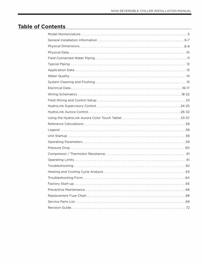
Table of ContentsModel Nomenclature . . . . . . . . . . . . . . . . . . . . . . . . . . . . . . . . . . . . . . . . . . . . . . . . . . . . . . . . . . . . . . 5
General Installation Information . . . . . . . . . . . . . . . . . . . . . . . . . . . . . . . . . . . . . . . . . . . . . . . . . . 6-7
Physical Dimensions. . . . . . . . . . . . . . . . . . . . . . . . . . . . . . . . . . . . . . . . . . . . . . . . . . . . . . . . . . . . . 8-9
Physical Data . . . . . . . . . . . . . . . . . . . . . . . . . . . . . . . . . . . . . . . . . . . . . . . . . . . . . . . . . . . . . . . . . . . . 10
Field Connected Water Piping . . . . . . . . . . . . . . . . . . . . . . . . . . . . . . . . . . . . . . . . . . . . . . . . . . . . . .11
Typical Piping . . . . . . . . . . . . . . . . . . . . . . . . . . . . . . . . . . . . . . . . . . . . . . . . . . . . . . . . . . . . . . . . . . . 12
Application Data . . . . . . . . . . . . . . . . . . . . . . . . . . . . . . . . . . . . . . . . . . . . . . . . . . . . . . . . . . . . . . . . . 13
Water Quality . . . . . . . . . . . . . . . . . . . . . . . . . . . . . . . . . . . . . . . . . . . . . . . . . . . . . . . . . . . . . . . . . . . 14
System Cleaning and Flushing. . . . . . . . . . . . . . . . . . . . . . . . . . . . . . . . . . . . . . . . . . . . . . . . . . . . . 15
Electrical Data . . . . . . . . . . . . . . . . . . . . . . . . . . . . . . . . . . . . . . . . . . . . . . . . . . . . . . . . . . . . . . . . . 16-17
Wiring Schematics . . . . . . . . . . . . . . . . . . . . . . . . . . . . . . . . . . . . . . . . . . . . . . . . . . . . . . . . . . . . 18-22
Field Wiring and Control Setup . . . . . . . . . . . . . . . . . . . . . . . . . . . . . . . . . . . . . . . . . . . . . . . . . . . . 23
HydroLink Supervisory Control . . . . . . . . . . . . . . . . . . . . . . . . . . . . . . . . . . . . . . . . . . . . . . . . .24-25
HydroLink Aurora Control. . . . . . . . . . . . . . . . . . . . . . . . . . . . . . . . . . . . . . . . . . . . . . . . . . . . . .26-32
Using the HydroLink Aurora Color Touch Tablet . . . . . . . . . . . . . . . . . . . . . . . . . . . . . . . . . . 33-57
Reference Calculations . . . . . . . . . . . . . . . . . . . . . . . . . . . . . . . . . . . . . . . . . . . . . . . . . . . . . . . . . . .58
Legend . . . . . . . . . . . . . . . . . . . . . . . . . . . . . . . . . . . . . . . . . . . . . . . . . . . . . . . . . . . . . . . . . . . . . . . . .58
Unit Startup . . . . . . . . . . . . . . . . . . . . . . . . . . . . . . . . . . . . . . . . . . . . . . . . . . . . . . . . . . . . . . . . . . . . .58
Operating Parameters . . . . . . . . . . . . . . . . . . . . . . . . . . . . . . . . . . . . . . . . . . . . . . . . . . . . . . . . . . . .59
Pressure Drop . . . . . . . . . . . . . . . . . . . . . . . . . . . . . . . . . . . . . . . . . . . . . . . . . . . . . . . . . . . . . . . . . . 60
Compressor / Thermistor Resistance . . . . . . . . . . . . . . . . . . . . . . . . . . . . . . . . . . . . . . . . . . . . . . . 61
Operating Limits . . . . . . . . . . . . . . . . . . . . . . . . . . . . . . . . . . . . . . . . . . . . . . . . . . . . . . . . . . . . . . . . . 61
Troubleshooting . . . . . . . . . . . . . . . . . . . . . . . . . . . . . . . . . . . . . . . . . . . . . . . . . . . . . . . . . . . . . . . . .62
Heating and Cooling Cycle Analysis . . . . . . . . . . . . . . . . . . . . . . . . . . . . . . . . . . . . . . . . . . . . . . . .63
Troubleshooting Form . . . . . . . . . . . . . . . . . . . . . . . . . . . . . . . . . . . . . . . . . . . . . . . . . . . . . . . . . . . .64
Factory Start-up . . . . . . . . . . . . . . . . . . . . . . . . . . . . . . . . . . . . . . . . . . . . . . . . . . . . . . . . . . . . . . . . .65
Preventive Maintenance . . . . . . . . . . . . . . . . . . . . . . . . . . . . . . . . . . . . . . . . . . . . . . . . . . . . . . . . . .68
Replacement Fuse Chart. . . . . . . . . . . . . . . . . . . . . . . . . . . . . . . . . . . . . . . . . . . . . . . . . . . . . . . . . .68
Service Parts List . . . . . . . . . . . . . . . . . . . . . . . . . . . . . . . . . . . . . . . . . . . . . . . . . . . . . . . . . . . . . . . .69
Revision Guide. . . . . . . . . . . . . . . . . . . . . . . . . . . . . . . . . . . . . . . . . . . . . . . . . . . . . . . . . . . . . . . . . . . 72
4
ENVISION2 NXW REVERSIBLE CHILLER INSTALLATION MANUAL
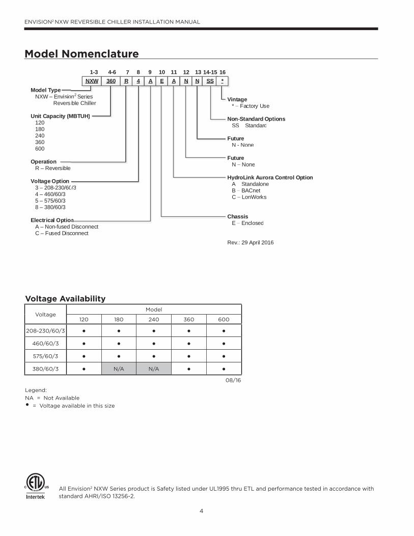
Model Nomenclature
All Envision2 NXW Series product is Safety listed under UL1995 thru ETL and performance tested in accordance with standard AHRI/ISO 13256-2.
Voltage Availability
VoltageModel
120 180 240 360 600
208-230/60/3 • • • • •460/60/3 • • • • •575/60/3 • • • • •380/60/3 • N/A N/A • •
08/16
Legend:
NA = Not Available
• = Voltage available in this size
Vintage * – Factory Use
Non-Standard Options SS – Standard
Future N - None
Future N – None HydroLink Aurora Control Option A – Standalone B – BACnet C – LonWorks
Chassis E – Enclosed
Rev.: 29 April 2016
Vintage * – Factory Use
Non-Standard Options SS – Standard
Future N - None
Future N – None
HydroLink Aurora Control Option A – Standalone B – BACnet C – LonWorks
Chassis E – Enclosed
Rev.: 29 April 2016
1-3 4-6 7 8 9
Model Type NXW – Envision2 Series Reversible Chiller
Unit Capacity (MBTUH) 120 180 240 360 600
Operation R – Reversible
Voltage Option 3 – 208-230/60/3 4 – 460/60/3 5 – 575/60/3 8 – 380/60/3
Electrical Option A – Non-fused Disconnect C – Fused Disconnect
10 11 13NXW 360 R 4 A E A N N
12
evisioversi
ty (M
SS14-15
*16
0/3
nnnnnnn
n2 Seriesible Chille
MBTUH)
s er
5
ENVISION2 NXW REVERSIBLE CHILLER INSTALLATION MANUAL
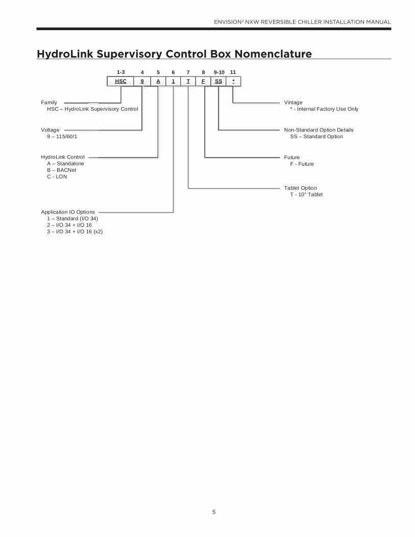
HydroLink Supervisory Control Box Nomenclature
HSCHSC 9 A 1 T F SS4 5 6 7 8 9-10
*111-3
Vintage * - Internal Factory Use Only
Non-Standard Option Details SS – Standard Option
Future F - Future
Tablet Option T - 10" Tablet
Family HSC – HydroLink Supervisory Control
Voltage 9 – 115/60/1
HydroLink Control A – Standalone B – BACNet C - LON
Application IO Options 1 – Standard (I/O 34) 2 – I/O 34 + I/O 16 3 – I/O 34 + I/O 16 (x2)
6
ENVISION2 NXW REVERSIBLE CHILLER INSTALLATION MANUAL
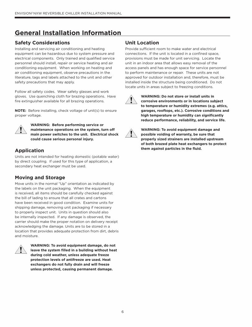
Safety ConsiderationsInstalling and servicing air conditioning and heating
equipment can be hazardous due to system pressure and
electrical components. Only trained and qualified service
personnel should install, repair or service heating and air
conditioning equipment. When working on heating and
air conditioning equipment, observe precautions in the
literature, tags and labels attached to the unit and other
safety precautions that may apply.
Follow all safety codes. Wear safety glasses and work
gloves. Use quenching cloth for brazing operations. Have
fire extinguisher available for all brazing operations.
NOTE: Before installing, check voltage of unit(s) to ensure
proper voltage.
WARNING: Before performing service or maintenance operations on the system, turn off main power switches to the unit. Electrical shock could cause serious personal injury.
ApplicationUnits are not intended for heating domestic (potable water)
by direct coupling. If used for this type of application, a
secondary heat exchanger must be used.
Moving and StorageMove units in the normal “Up” orientation as indicated by
the labels on the unit packaging. When the equipment
is received, all items should be carefully checked against
the bill of lading to ensure that all crates and cartons
have been received in good condition. Examine units for
shipping damage, removing unit packaging if necessary
to properly inspect unit. Units in question should also
be internally inspected. If any damage is observed, the
carrier should make the proper notation on delivery receipt
acknowledging the damage. Units are to be stored in a
location that provides adequate protection from dirt, debris
and moisture.
WARNING: To avoid equipment damage, do not leave the system filled in a building without heat during cold weather, unless adequate freeze protection levels of antifreeze are used. Heat exchangers do not fully drain and will freeze unless protected, causing permanent damage.
General Installation Information
Unit LocationProvide sufficient room to make water and electrical
connections. If the unit is located in a confined space,
provisions must be made for unit servicing. Locate the
unit in an indoor area that allows easy removal of the
access panels and has enough space for service personnel
to perform maintenance or repair. These units are not
approved for outdoor installation and, therefore, must be
installed inside the structure being conditioned. Do not
locate units in areas subject to freezing conditions.
WARNING: Do not store or install units in corrosive environments or in locations subject to temperature or humidity extremes (e.g. attics, garages, rooftops, etc.). Corrosive conditions and high temperature or humidity can significantly reduce performance, reliability, and service life. WARNING: To avoid equipment damage and possible voiding of warranty, be sure that properly sized strainers are installed upstream of both brazed plate heat exchangers to protect them against particles in the fluid.
7
ENVISION2 NXW REVERSIBLE CHILLER INSTALLATION MANUAL
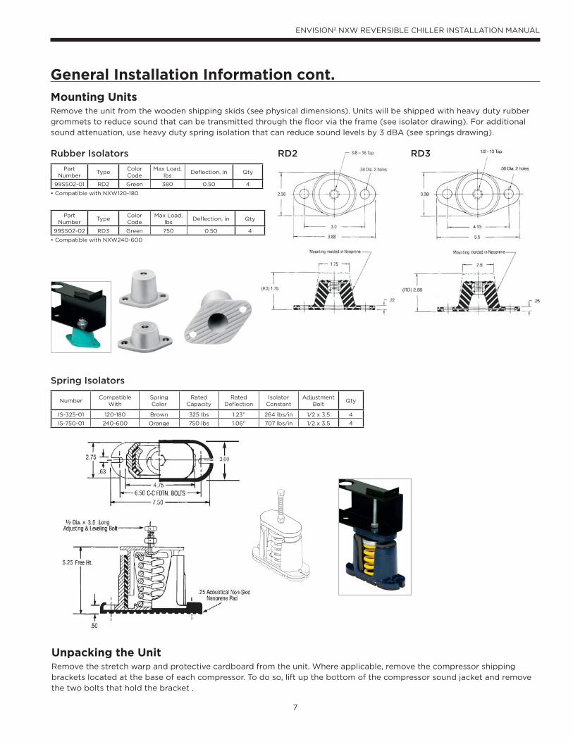
Mounting UnitsRemove the unit from the wooden shipping skids (see physical dimensions). Units will be shipped with heavy duty rubber
grommets to reduce sound that can be transmitted through the floor via the frame (see isolator drawing). For additional
sound attenuation, use heavy duty spring isolation that can reduce sound levels by 3 dBA (see springs drawing).
Unpacking the UnitRemove the stretch warp and protective cardboard from the unit. Where applicable, remove the compressor shipping
brackets located at the base of each compressor. To do so, lift up the bottom of the compressor sound jacket and remove
the two bolts that hold the bracket .
General Installation Information cont.
NumberCompatible
WithSpringColor
Rated Capacity
Rated Deflection
Isolator Constant
Adjustment Bolt
Qty
IS-325-01 120-180 Brown 325 lbs 1.23" 264 lbs/in 1/2 x 3.5 4
IS-750-01 240-600 Orange 750 lbs 1.06" 707 lbs/in 1/2 x 3.5 4
Spring Isolators
Rubber Isolators RD2 RD3
PartNumber
TypeColor Code
Max Load,lbs
Deflection, in Qty
99S502-01 RD2 Green 380 0.50 4
• Compatible with NXW120-180
PartNumber
TypeColor Code
Max Load,lbs
Deflection, in Qty
99S502-02 RD3 Green 750 0.50 4
• Compatible with NXW240-600
8
ENVISION2 NXW REVERSIBLE CHILLER INSTALLATION MANUAL
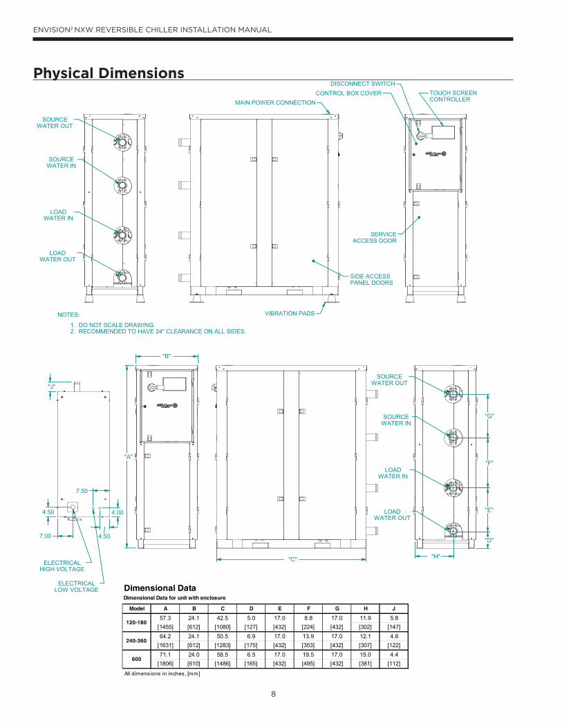
Physical Dimensions
Model A B C D E F G H J
Dimensional DataDimensional Data for unit with enclosure
120-180
240-360
600
9
ENVISION2 NXW REVERSIBLE CHILLER INSTALLATION MANUAL
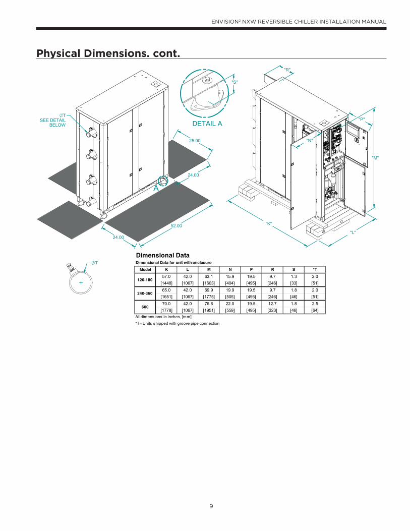
Physical Dimensions. cont.
Model K L M N P R S *T
Dimensional DataDimensional Data for unit with enclosure
120-180
240-360
600
10
ENVISION2 NXW REVERSIBLE CHILLER INSTALLATION MANUAL
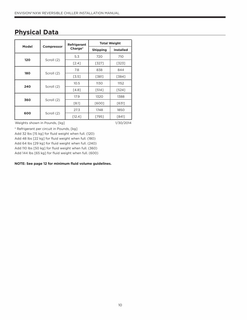
Physical Data
Model CompressorRefrigerant
Charge*
Total Weight
Shipping Installed
120 Scroll (2)5.3 720 710
[2.4] [327] [323]
180 Scroll (2)7.8 838 844
[3.5] [381] [384]
240 Scroll (2)10.5 1130 1152
[4.8] [514] [524]
360 Scroll (2)17.9 1320 1388
[8.1] [600] [631]
600 Scroll (2)27.3 1748 1850
[12.4] [795] [841]
Weights shown in Pounds, [kg] 1/30/2014
* Refrigerant per circuit in Pounds, [kg]
Add 32 lbs [15 kg] for fluid weight when full. (120)
Add 48 lbs [22 kg] for fluid weight when full. (180)
Add 64 lbs [29 kg] for fluid weight when full. (240)
Add 110 lbs [50 kg] for fluid weight when full. (360)
Add 144 lbs [65 kg] for fluid weight when full. (600)
NOTE: See page 12 for minimum fluid volume guidelines.
11
ENVISION2 NXW REVERSIBLE CHILLER INSTALLATION MANUAL
General
System piping should be kept as simple as possible to
minimize the pressure drop, but hand valves should be field
installed to facilitate unit servicing. The piping installation
should provide service personnel with the ability to measure
and/or monitor water temperatures and pressures.
Source and load fluid connections are provided with 2-inch
[50.8mm] Victaulic grooved nipples (see Figure 4). Each
nipple will also have a PT port installed for test and balance
purposes. It will be the installing contractor’s responsibility
to adequately support incoming piping to avoid damage to
the unit’s piping or heat exchangers. The water lines should
be routed so as not to interfere with access to the unit.
For any installation where the transmission of vibration
through the piping connections could cause unacceptable
noise levels in occupied spaces it is important to provide
adequate vibration damping. One method is to use the
optional Adapter Hose Kit (kit number TKC16S-4). This Kit
consists of four pieces of a braided stainless steel flexible
hose with a 2” Victaulic connection on one end and a 2”
MPT connection with pipe union on the other. Overall length
of each piece is 18”.
NOTE: Units are factory run-tested using propylene
glycol. Prior to connecting piping to unit, thoroughly flush
heat exchangers.
Before final connection to the unit, the supply and return
hose kits must be connected to each other, bypassing
the unit, and the system flushed to remove dirt, piping
chips and other foreign material. Normally, a combination
balancing and close-off (ball) valve is installed at the return,
and a rated gate or ball valve is installed at the supply. The
return valve can be adjusted to obtain the proper water
flow. The valves allow the unit to be removed for servicing.
The proper water flow must be delivered to each unit
whenever the unit heats or cools. The proper flow rate
cannot be accurately set without measuring the water
pressure drop through the refrigerant-to-water heat
exchanger. A 3 GPM flow rate per ton [0.054 LPS per kW] of cooling capacity (2.25 GPM per ton [0.0404 LPS per kW] minimum) is required.
Field Connected Water Piping
CAUTION: Remove the plastic protective caps in the ends of each of the four water pipes on the heat exchangers prior to piping connection. Failure to remove the caps will result in serious damage and could void the warranty.
NOTE: The placement and connection of the water
circulating pump(s) must be taken into consideration prior
to designing the final water piping systems.
Closed Loop Tower/Boiler SystemsThe water loop is usually maintained between 60°F [15.5°C]
and 90°F [32.2°C] for proper heating and cooling operation.
This is accomplished with a cooling tower and a boiler.
To reject excess heat from the condenser water loop, the
use of a closed-circuit evaporative cooler or an open type
cooling tower with a secondary heat exchanger between
the tower and the condenser water loop is recommended.
If an open type cooling tower is used without a secondary
heat exchanger, continuous chemical treatment and filtering
of the water must be performed to ensure the water is free
from damaging materials.
CAUTION: Water piping exposed to outside temperature may be subject to freezing.
Open Loop Well Water SystemsInstallation of an open loop system is not recommended
without using a secondary heat exchanger unless water
quality guidelines are met.
Earth Coupled SystemsAll supply and return water piping should be insulated to
prevent excess condensation from forming on the water
lines. Ensure pumping system is capable of providing
adequate flow rate at the system pressure drop, 3.0 GPM
per ton [0.054 LPS per kW] (source side) is recommended.
Antifreeze in the loop is strongly recommended.
12
ENVISION2 NXW REVERSIBLE CHILLER INSTALLATION MANUAL
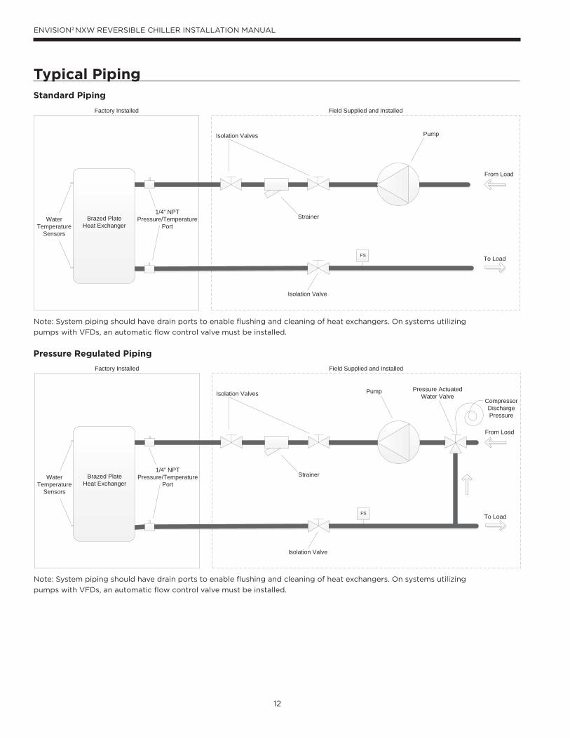
Typical Piping
FS
Brazed PlateHeat Exchanger
Isolation Valves
Isolation Valve
Strainer
Pump
From Load
To Load
WaterTemperature
Sensors
Field Supplied and InstalledFactory Installed
1/4” NPTPressure/Temperature
Port
Pressure ActuatedWater Valve
CompressorDischargePressure
FS
Brazed PlateHeat Exchanger
Isolation Valves
Isolation Valve
Strainer
Pump
From Load
To Load
WaterTemperature
Sensors
Field Supplied and InstalledFactory Installed
1/4” NPTPressure/Temperature
Port
Standard Piping
Pressure Regulated Piping
Note: System piping should have drain ports to enable flushing and cleaning of heat exchangers. On systems utilizing
pumps with VFDs, an automatic flow control valve must be installed.
Note: System piping should have drain ports to enable flushing and cleaning of heat exchangers. On systems utilizing
pumps with VFDs, an automatic flow control valve must be installed.
13
ENVISION2 NXW REVERSIBLE CHILLER INSTALLATION MANUAL
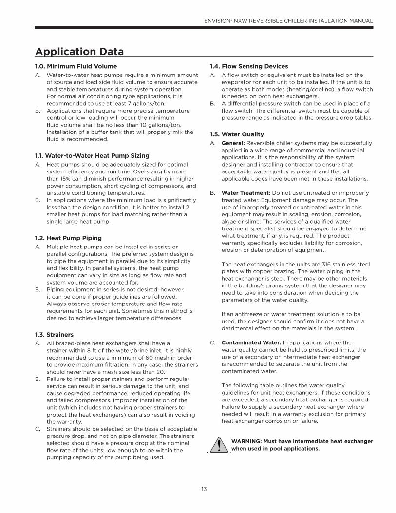
Application Data1.0. Minimum Fluid Volume
A. Water-to-water heat pumps require a minimum amount of source and load side fl uid volume to ensure accurate and stable temperatures during system operation. For normal air conditioning type applications, it is recommended to use at least 7 gallons/ton.
B. Applications that require more precise temperature control or low loading will occur the minimum fl uid volume shall be no less than 10 gallons/ton. Installation of a buffer tank that will properly mix the fl uid is recommended.
1.1. Water-to-Water Heat Pump Sizing
A. Heat pumps should be adequately sized for optimal system effi ciency and run time. Oversizing by more than 15% can diminish performance resulting in higher power consumption, short cycling of compressors, and unstable conditioning temperatures.
B. In applications where the minimum load is signifi cantly less than the design condition, it is better to install 2 smaller heat pumps for load matching rather than a single large heat pump.
1.2. Heat Pump Piping
A. Multiple heat pumps can be installed in series or parallel confi gurations. The preferred system design is to pipe the equipment in parallel due to its simplicity and fl exibility. In parallel systems, the heat pump equipment can vary in size as long as fl ow rate and system volume are accounted for.
B. Piping equipment in series is not desired; however, it can be done if proper guidelines are followed. Always observe proper temperature and fl ow rate requirements for each unit. Sometimes this method is desired to achieve larger temperature differences.
1.3. Strainers
A. All brazed-plate heat exchangers shall have a strainer within 8 ft of the water/brine inlet. It is highly recommended to use a minimum of 60 mesh in order to provide maximum fi ltration. In any case, the strainers should never have a mesh size less than 20.
B. Failure to install proper stainers and perform regular service can result in serious damage to the unit, and cause degraded performance, reduced operating life and failed compressors. Improper installation of the unit (which includes not having proper strainers to protect the heat exchangers) can also result in voiding the warranty.
C. Strainers should be selected on the basis of acceptable pressure drop, and not on pipe diameter. The strainers selected should have a pressure drop at the nominal fl ow rate of the units; low enough to be within the pumping capacity of the pump being used.
1.4. Flow Sensing Devices
A. A fl ow switch or equivalent must be installed on the evaporator for each unit to be installed. If the unit is to operate as both modes (heating/cooling), a fl ow switch is needed on both heat exchangers.
B. A differential pressure switch can be used in place of a fl ow switch. The differential switch must be capable of pressure range as indicated in the pressure drop tables.
1.5. Water Quality
A. General: Reversible chiller systems may be successfully applied in a wide range of commercial and industrial applications. It is the responsibility of the system designer and installing contractor to ensure that acceptable water quality is present and that all applicable codes have been met in these installations.
B. Water Treatment: Do not use untreated or improperly treated water. Equipment damage may occur. The use of improperly treated or untreated water in this equipment may result in scaling, erosion, corrosion, algae or slime. The services of a qualifi ed water treatment specialist should be engaged to determine what treatment, if any, is required. The product warranty specifi cally excludes liability for corrosion, erosion or deterioration of equipment.
The heat exchangers in the units are 316 stainless steel plates with copper brazing. The water piping in the heat exchanger is steel. There may be other materials in the building’s piping system that the designer may need to take into consideration when deciding the parameters of the water quality.
If an antifreeze or water treatment solution is to be used, the designer should confi rm it does not have a detrimental effect on the materials in the system.
C. Contaminated Water: In applications where the water quality cannot be held to prescribed limits, the use of a secondary or intermediate heat exchanger is recommended to separate the unit from the contaminated water.
The following table outlines the water quality guidelines for unit heat exchangers. If these conditions are exceeded, a secondary heat exchanger is required. Failure to supply a secondary heat exchanger where needed will result in a warranty exclusion for primary heat exchanger corrosion or failure.
WARNING: Must have intermediate heat exchanger when used in pool applications.
14
ENVISION2 NXW REVERSIBLE CHILLER INSTALLATION MANUAL
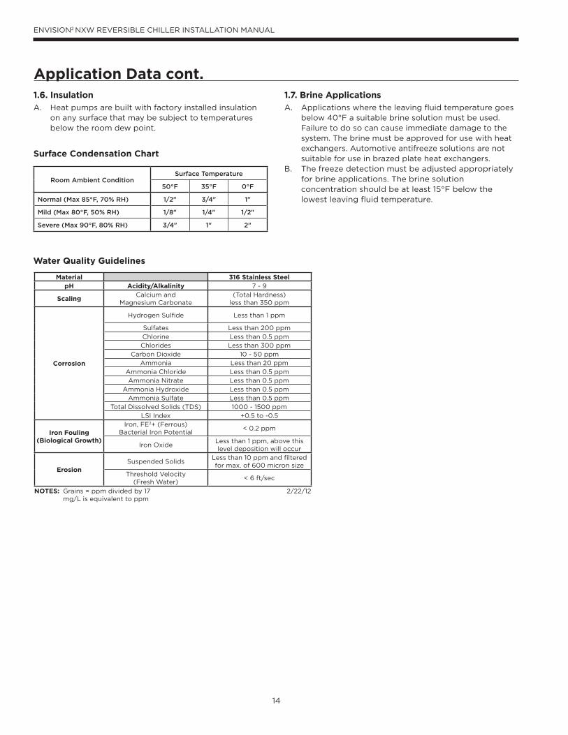
1.6. Insulation
A. Heat pumps are built with factory installed insulation on any surface that may be subject to temperatures below the room dew point.
1.7. Brine Applications
A. Applications where the leaving fl uid temperature goes below 40°F a suitable brine solution must be used. Failure to do so can cause immediate damage to the system. The brine must be approved for use with heat exchangers. Automotive antifreeze solutions are not suitable for use in brazed plate heat exchangers.
B. The freeze detection must be adjusted appropriately for brine applications. The brine solution concentration should be at least 15°F below the lowest leaving fl uid temperature.
Water Quality Guidelines
Application Data cont.
Surface Condensation Chart
Room Ambient ConditionSurface Temperature
50°F 35°F 0°F
Normal (Max 85°F, 70% RH) 1/2" 3/4" 1"
Mild (Max 80°F, 50% RH) 1/8" 1/4" 1/2"
Severe (Max 90°F, 80% RH) 3/4" 1" 2"
Material 316 Stainless SteelpH Acidity/Alkalinity 7 - 9
ScalingCalcium and
Magnesium Carbonate(Total Hardness)
less than 350 ppm
Corrosion
Hydrogen Sulfide Less than 1 ppm
Sulfates Less than 200 ppm
Chlorine Less than 0.5 ppm
Chlorides Less than 300 ppm
Carbon Dioxide 10 - 50 ppm
Ammonia Less than 20 ppm
Ammonia Chloride Less than 0.5 ppm
Ammonia Nitrate Less than 0.5 ppm
Ammonia Hydroxide Less than 0.5 ppm
Ammonia Sulfate Less than 0.5 ppm
Total Dissolved Solids (TDS) 1000 - 1500 ppm
LSI Index +0.5 to -0.5
Iron Fouling(Biological Growth)
Iron, FE2+ (Ferrous)Bacterial Iron Potential
< 0.2 ppm
Iron OxideLess than 1 ppm, above this level deposition will occur
ErosionSuspended Solids
Less than 10 ppm and filtered for max. of 600 micron size
Threshold Velocity(Fresh Water)
< 6 ft/sec
NOTES: Grains = ppm divided by 17 mg/L is equivalent to ppm
2/22/12
15
ENVISION2 NXW REVERSIBLE CHILLER INSTALLATION MANUAL
System Cleaning and Flushing
Cleaning and FlushingPrior to start up of any heat pump, the water circulating
system must be cleaned and flushed of all dirt and debris.
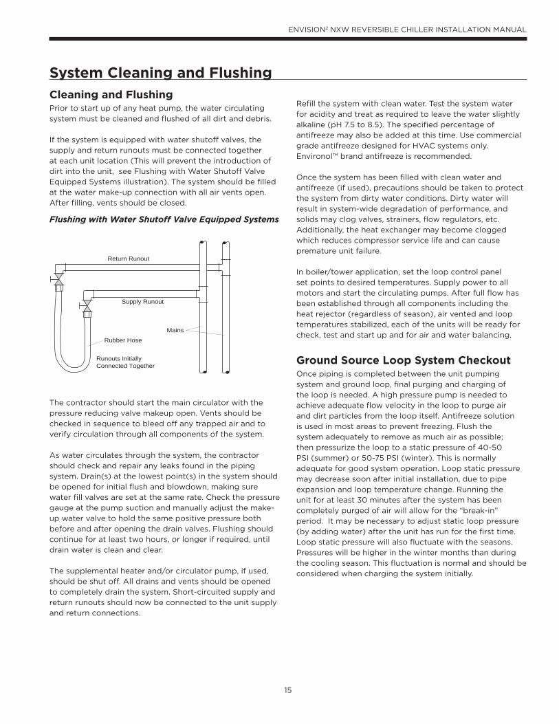
If the system is equipped with water shutoff valves, the
supply and return runouts must be connected together
at each unit location (This will prevent the introduction of
dirt into the unit, see Flushing with Water Shutoff Valve
Equipped Systems illustration). The system should be filled
at the water make-up connection with all air vents open.
After filling, vents should be closed.
The contractor should start the main circulator with the
pressure reducing valve makeup open. Vents should be
checked in sequence to bleed off any trapped air and to
verify circulation through all components of the system.
As water circulates through the system, the contractor
should check and repair any leaks found in the piping
system. Drain(s) at the lowest point(s) in the system should
be opened for initial flush and blowdown, making sure
water fill valves are set at the same rate. Check the pressure
gauge at the pump suction and manually adjust the make-
up water valve to hold the same positive pressure both
before and after opening the drain valves. Flushing should
continue for at least two hours, or longer if required, until
drain water is clean and clear.
The supplemental heater and/or circulator pump, if used,
should be shut off. All drains and vents should be opened
to completely drain the system. Short-circuited supply and
return runouts should now be connected to the unit supply
and return connections.
Refill the system with clean water. Test the system water
for acidity and treat as required to leave the water slightly
alkaline (pH 7.5 to 8.5). The specified percentage of
antifreeze may also be added at this time. Use commercial
grade antifreeze designed for HVAC systems only.
Environol™ brand antifreeze is recommended.
Once the system has been filled with clean water and
antifreeze (if used), precautions should be taken to protect
the system from dirty water conditions. Dirty water will
result in system-wide degradation of performance, and
solids may clog valves, strainers, flow regulators, etc.
Additionally, the heat exchanger may become clogged
which reduces compressor service life and can cause
premature unit failure.
In boiler/tower application, set the loop control panel
set points to desired temperatures. Supply power to all
motors and start the circulating pumps. After full flow has
been established through all components including the
heat rejector (regardless of season), air vented and loop
temperatures stabilized, each of the units will be ready for
check, test and start up and for air and water balancing.
Ground Source Loop System CheckoutOnce piping is completed between the unit pumping
system and ground loop, final purging and charging of
the loop is needed. A high pressure pump is needed to
achieve adequate flow velocity in the loop to purge air
and dirt particles from the loop itself. Antifreeze solution
is used in most areas to prevent freezing. Flush the
system adequately to remove as much air as possible;
then pressurize the loop to a static pressure of 40-50
PSI (summer) or 50-75 PSI (winter). This is normally
adequate for good system operation. Loop static pressure
may decrease soon after initial installation, due to pipe
expansion and loop temperature change. Running the
unit for at least 30 minutes after the system has been
completely purged of air will allow for the “break-in”
period. It may be necessary to adjust static loop pressure
(by adding water) after the unit has run for the first time.
Loop static pressure will also fluctuate with the seasons.
Pressures will be higher in the winter months than during
the cooling season. This fluctuation is normal and should be
considered when charging the system initially.
Return Runout
Supply Runout
Mains
Rubber Hose
Runouts InitiallyConnected Together
Flushing with Water Shutoff Valve Equipped Systems
16
ENVISION2 NXW REVERSIBLE CHILLER INSTALLATION MANUAL
Electrical Data
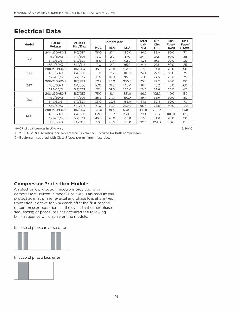
Compressor Protection ModuleAn electronic protection module is provided with compressors utilized in model size 600. This module will protect against phase reversal and phase loss at start-up. Protection is active for 5 seconds after the first second of compressor operation. In the event that either phase sequencing or phase loss has occurred the following blink sequence will display on the module.
ModelRated
VoltageVoltageMin/Max
Compressor1 TotalUnitFLA
MinCircAmp
MinFuse/HACR
MaxFuse/HACR2MCC RLA LRA
120
208-230/60/3 187/253 36.0 23.1 160.0 46.2 52.0 60.0 70
460/60/3 414/506 19.0 12.2 87.0 24.4 27.5 30.0 35
575/60/3 517/633 13.5 8.7 62.0 17.4 19.6 20.0 25
380/60/3 342/418 19.0 12.2 95.0 24.4 27.5 30.0 35
180
208-230/60/3 187/253 45.0 28.8 235.0 57.6 64.8 70.0 90
460/60/3 414/506 19.0 12.2 110.0 24.4 27.5 30.0 35
575/60/3 517/633 16.5 10.9 95.0 21.8 24.5 25.0 35
240
208-230/60/3 187/253 52.2 35.2 250.0 70.4 79.2 80.0 110
460/60/3 414/506 27.0 19.2 140.0 38.4 43.2 45.0 60
575/60/3 517/633 19.1 14.5 100.0 29.0 32.6 35.0 45
360
208-230/60/3 187/253 75.0 48.1 351.0 96.2 108.2 110.0 150
460/60/3 414/506 38.6 24.7 197.0 49.4 55.6 60.0 80
575/60/3 517/633 35.0 22.4 135.0 44.8 50.4 60.0 70
380/60/3 342/418 51.0 32.7 239.0 65.4 73.6 80.0 100
600
208-230/60/3 187/253 128.0 91.4 560.0 182.8 205.7 250
460/60/3 414/506 62.0 39.7 260.0 79.4 89.3 100.0 125
575/60/3 517/633 45.0 28.8 210.0 57.6 64.8 70.0 90
380/60/3 342/418 72.0 46.2 310.0 92.4 104.0 110.0 150
HACR circuit breaker in USA only 8/18/16
1 - MCC, RLA, & LRA rating per compressor. Breaker & FLA sized for both compressors.
2 - Equipment supplied with Class J fuses per minimum fuse size.
17
ENVISION2 NXW REVERSIBLE CHILLER INSTALLATION MANUAL
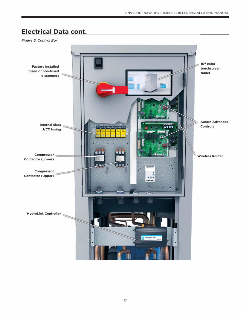
Electrical Data cont.Figure 6: Control Box
Electrical Data cont.Figure 6: Control Box
10" color
touchscreen
tablet
Aurora Advanced
Controls
Factory installed
fused or non-fused
disconnect
Internal class
J/CC fusing
Compressor
Contactor (Upper)
Compressor
Contactor (Lower)Wireless Router
HydroLink Controller

18
ENVISION2 NXW REVERSIBLE CHILLER INSTALLATION MANUAL
Wiring Schematics
160
Compressor A T2
Red (23)
Compressor A T1
SCT
SUC
P
White (24)Black (25)
HW HW
Blue (89)Blue (90)
Red (91)Red (92)
White (31)FLOW METER
PRESSURE TRANSDUCER
PRESSURE TRANSDUCER
P8
MOT
OR P6
RS48
5 P7
ZONE P9
ABC
STEP
PER
ANA
ACC2
DHDI
V
NO
CO
M
K6
NO
CO
M
K5
C R L1 L1 L2 L2P1
2P1
0P5
P11
CR(-)(+) CR(-)(+) CR(-)(+)
P4P2
K1K2
K3
HA2
HA1
SGI
LOO
PVS
DATA
VSPU
MP
PUMP
SLAV
EP3
V+CRTXRX +5
P14
LLT
P1LA
TFL
OW
LWT
EWT
CT2
43
CT2
43
CT1
21
CT1
21
StatusG
DISC
HP1
6
P17
P18
P15
(Aurora Expansion Board A)
AXB™-A
SW1
Modbus Add. IDFuture Use
12345
ONOFF
Future UseAcc 2 – Dip 1Acc 2 – Dip 2
See Figure 1 for DHW wiring.
Current Transducer (CT)
ThermistorLight emi tting diode - GreenRelay coil
Capacitor w/ bleed resistorSwitch - Condensate overflowSwitch - High pressure
Switch - Low pressure
Polarized connector
Factory Low voltage wi ringFactory Line vol tage wiringField low voltage wiringField l ine voltage wi ringOptional blockDC Voltage PCB tracesJunctionQuick connect terminalWire nut
Field wi re lug
Ground
Fuse
EWT – Entering Water TemperatureLLT – Liquid Line TemperatureLWT – Leaving Water TemperatureSCP – Suction PressureSCT – Suction Temperature
Legend
Relay Con tacts-N.O., N.C.
GT
132P
L1
Breaker
CS
+5C
CC
21
INOU
T+5
S
To ABC-A
EX-29EX-28EX-27EX-26
EX-22EX-21
Blue (22)Blue (21)
EX-33EX-34
EX-36EX-37
EX-35
EX-31
EX-25EX-24EX-23
White (26)
White (27)
Purple (28)
Purple (29)
Brown (33)
Brown (34)
Red (37)
White (36)
Black (35)
EX-41EX-40EX-39EX-38 Blue (38)
Pink (39)
Yellow (40)
Purple (41)
Blue/White (85)
Yellow/White (87)
Pink/White (86)
Purple/White (88)
2
13
4
COMOUT
5 VDCN/A
2
13
4COMOUT
5 VDC
N/A
EX-32 Green (32)
“EX” Connector (twist lock)
27 28 33 34 41 42 43 44 45 46 47 48 49 50 51 52 53 54 55 56 57 58
Sou rce SCT
Re d
Sou rce SCP
21 22 23 24 25 26 29 30 31 32 35 36 37 38 39 40
Sou rce EWT
Sou rce LW T
GN
D
OU
T2 3
2
Flow M ete r
3+V1
5 V
DC
Pow er Sup ply
Sou rce LL T
Gr ee n
Source DI SCH
Lo ad SCT
Re d
Lo ad SCP
Lo ad EWT
Lo ad LW T
GN
D
OU
T2 3
2
Flow M ete r
3+V1
5 V
DC
Pow er Sup ply
Lo ad LL T
Gr ee n
Loa d DI SCH
Note 1
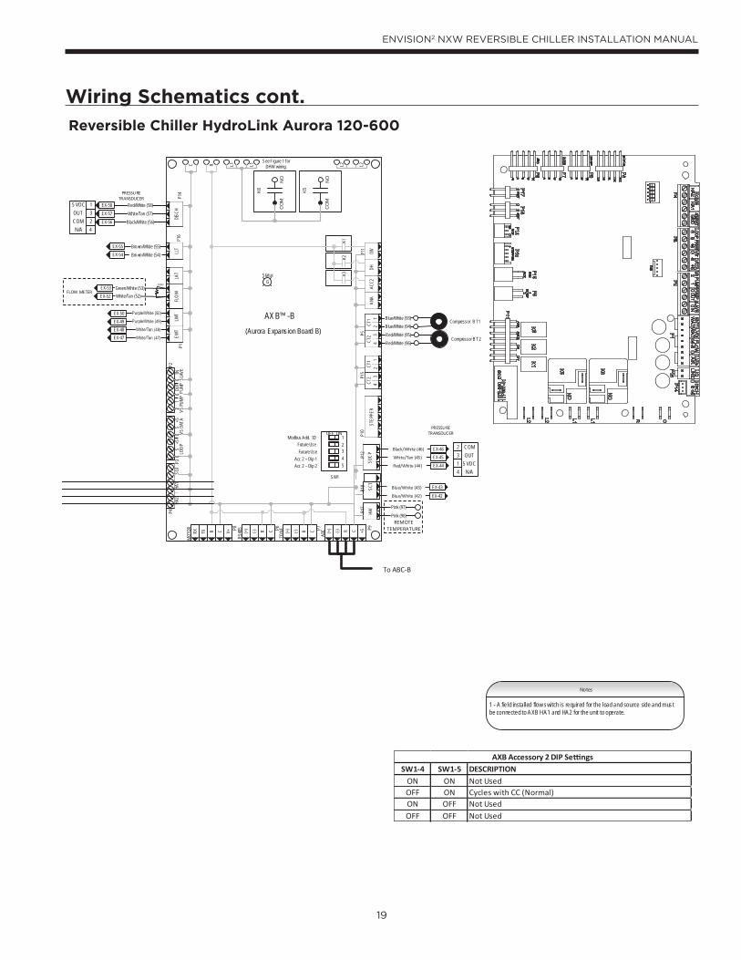
Reversible Chiller HydroLink Aurora 120-600
19
ENVISION2 NXW REVERSIBLE CHILLER INSTALLATION MANUAL
Wiring Schematics cont.
Notes
Compressor B T2
Compressor B T1
SCT
SUC
PHW HW
Blue/White (93)Blue/White (94)Red/White (95)Red/White (96)
P8
MOT
OR P6
RS48
5 P7
ZONE P9
ABC
STEP
PER
ANA
ACC2
DHDI
V
NO
CO
M
K6
NO
CO
M
K5
C R L1 L1 L2 L2P1
2P1
0P5
P11
CR(-)(+) CR(-)(+) CR(-)(+)
P4P2
K1K2
K3
HA2
HA1
SGI
LOO
PVS
DATA
VSPU
MP
PUMP
SLAV
EP3
V+CRTXRX +5
P14
LLT
P1LA
TFL
OW
LWT
EWT
CT2
43
CT2
43
CT1
21
CT1
21
StatusG
DISC
HP1
6
P17
P18
P15
(Aurora Expansion Board B)
AXB™-B
SW1
Modbus Add. IDFuture Use
12345
ONOFF
Future UseAcc 2 – Dip 1Acc 2 – Dip 2
See Figure 1 for DHW wiring.
CS
+5C
CC
21
INOU
T+5
S
To ABC-B
EX-50EX-49EX-48EX-47
EX-43
EX-42
Blue/White (43)
Blue/White (42)
EX-54EX-55
Red/White (58)
Black/White (56)
White/Tan (57)
PRESSURE TRANSDUCER
EX-57EX-58
EX-56
White/Tan (52)FLOW METER
EX-52
PRESSURE TRANSDUCER
EX-46EX-45EX-44Red/White (44)
White/Tan (45)
Black/White (46)
Brown/White (54)Brown/White (55)
Pink (97)
Pink (98)REMOTE
TEMPERATURE
2
13
4
COMOUT
5 VDCN/A
Green/White (53)EX-53
2
13
4COMOUT
5 VDC
N/A
1 - A field installed flow switch is required for the load and source side and must be connected to AXB HA1 and HA2 for the unit to operate.
SW1-4 SW1-5 DESCRIPTIONON ON Not UsedOFF ON Cycles with CC (Normal)ON OFF Not UsedOFF OFF Not Used
AXB Accessory 2 DIP Se ngs
160
Reversible Chiller HydroLink Aurora 120-600
20
ENVISION2 NXW REVERSIBLE CHILLER INSTALLATION MANUAL
Wiring Schematics cont.
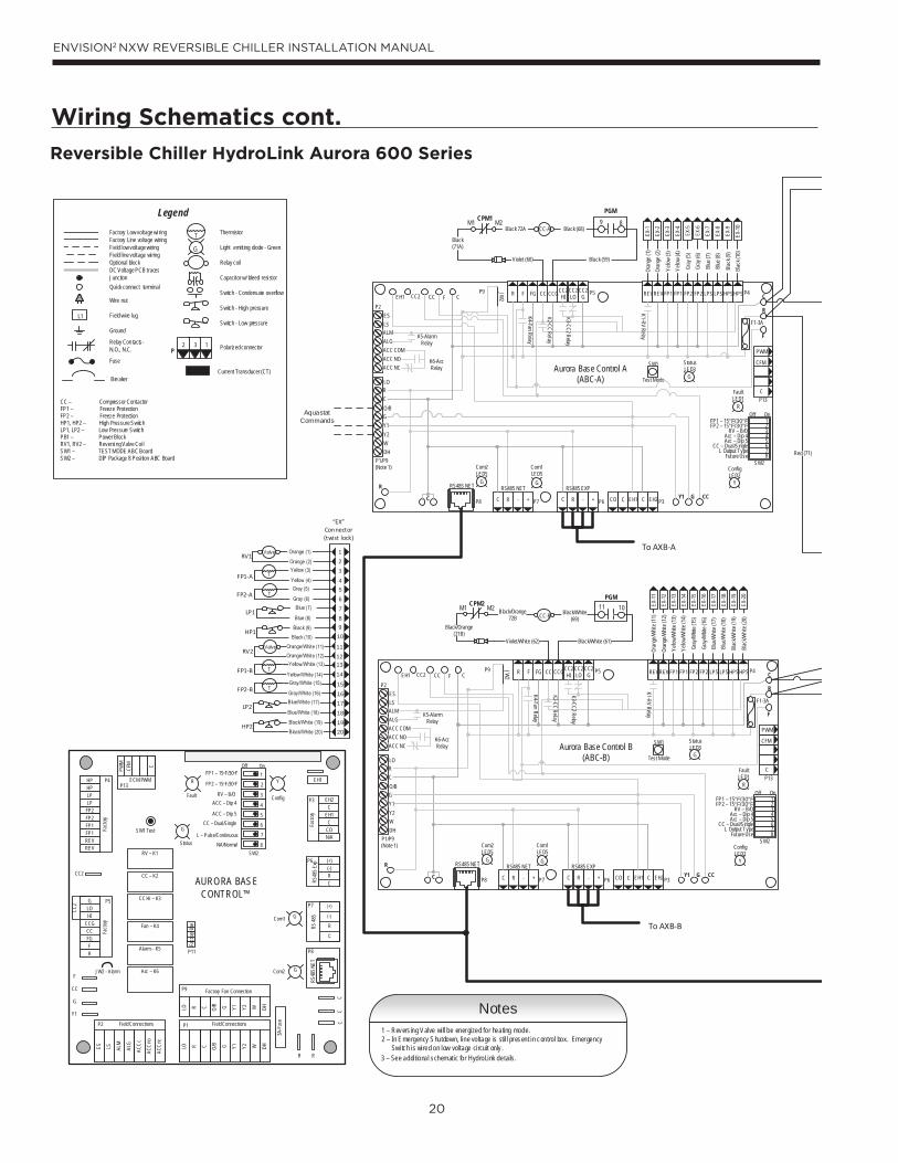
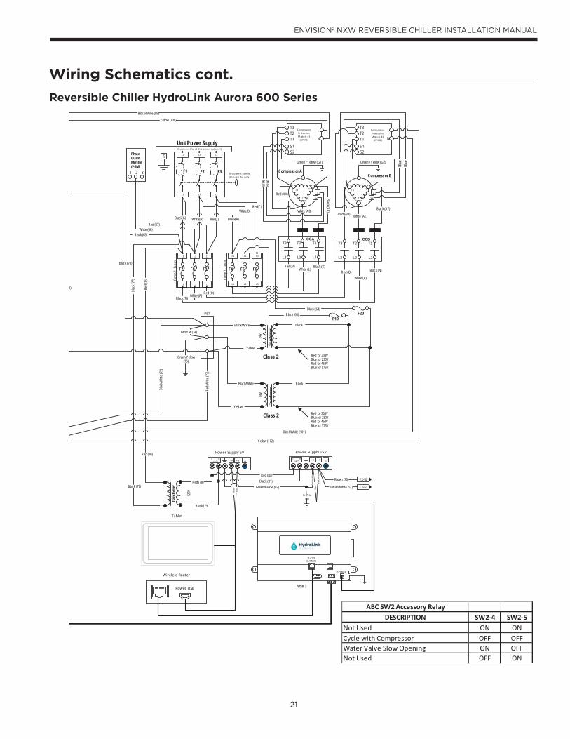
Reversible Chiller HydroLink Aurora 600 Series
CC2
EH1
Fact
ory
Faul t
ALG
ALMLSES ACC
c
Status
AURORA BASE CONTROL™
RV – K1
CC2
CC – K2
CC Hi – K3
Fan – K4
Alarm – K5
Acc – K6
ACC
no
ACC
nc
O/BCRLO G Y1 Y2 W DH
3A-Fu
se
O/BCRLO G Y1 Y2 W DH
LOG
HICCGCCFGFR
HPHPLP
FP2FP2FP1
REVREV
CFM
PWM
ECM PWM
Fact
ory
Factory Fan Connection
R R
CC
C
RS 48
5
EH2C
EH1C
CO
(+)(-)RCRS
485 E
xpFa
ctory
Com1
Com2
Config
G
G
G
YR
SW1 Test
FP1 – 15oF/30oF
JW2 - Alarm
P11
P5
P2 P1
P8
P7
P9
P6
P3
SW2
P13P4 FP2 – 15oF/30oF
RV – B/OACC – Dip 4
ACC – Dip 5CC – Dual/Single
L – Pulse/Continuous NA/Normal
Fact
ory U
se
Fi eld ConnectionsField Connections
C
LP
FP1
F
CC
G
Y1
1
2
3
4
5
6
7
8
Off On
N/A
RS48
5 NET
Notes1 – Revers ing Valve will be energized for heating mode.2 – In Emergency Shutdown, line voltage is stil l present in control box. Emergency Switch is wired on low voltage circuit only .3 – See additional schematic for HydroLink details.
Current Transducer (CT)
Thermistor
Light emi tting diode - Green
Relay coil
Capacitor w/ bleed resistor
Switch - Condensate overflow
Switch - High pressure
Switch - Low pressure
Polarized connector
Factory Low voltage wi ringFactory Line vol tage wiringField low voltage wiringField l ine voltage wi ringOptional blockDC Voltage PCB tracesJunctionQuick connect terminal
Wire nut
Field wi re lug
Ground
Fuse
Legend
Relay Con tacts-N.O., N.C.
G
T
132P
L1
Breaker
CC – Compressor Contactor FP1 – Freeze Protection FP2 – Freeze ProtectionHP1, HP2 – High Pressure SwitchLP1, LP2 – Low Pressure SwitchPB1 – Power BlockRV1, RV2 – Reversing Valve Coi lSW1 – TEST MODE ABC BoardSW2 – DIP Package 8 Posi tion ABC Board
CFM
P13
P4
SW1
P5JW2
P9
LO
O/B
Y2WDH
P8 P7
RS485 NET RS485 NET
P6
RS485 EXP
P3
SW2
On
Future Use L Output Type
CC – Dual/SingleAcc – Dip 5Acc – Dip 4
RV – B/OFP2 – 15°F/30°FFP1 – 15°F/30°F
Com1LED5
Com2LED5
Test Mode
F1-3A
P1/P9
C
PWM
12345678
ALMALGACC COMACC NOACC NC
RC
GY1
EH2CEH1CCOC R - +C R - +
Off
Faul tLED1
R
StatusLED3
ConfigLED2
CC2 CC F C R F FG CC CCGCC2HI
CC2LO
CC2G REVREV FP1 FP1 FP2 FP2 LPS LPSHPSHPS
Aurora Base Control A(ABC-A)
K1-RV Relay
K2-CC Relay
K3-CC2 Relay
K4-Fan RelayK5-Alarm Relay
K6-Acc Relay
F
R
C
CCGY1C
R
ESLS
P2EH1
YG G
G
CFM
P13
P4
SW1
P5JW2
P9
LO
O/B
Y2WDH
P8 P7
RS485 NET RS485 NET
P6
RS485 EXP
P3
SW2
On
Future Use L Output Type
CC – Dual/SingleAcc – Dip 5Acc – Dip 4
RV – B/OFP2 – 15°F/30°FFP1 – 15°F/30°F
Com1LED5
Com2LED5
Test Mode
F1-3A
C
PWM
12345678
ALMALGACC COMACC NOACC NC
RC
GY1
EH2CEH1CCOC R - +C R - +
Off
Faul tLED1
R
StatusLED3
ConfigLED2
CC2 CC F C R F FG CC CCGCC2HI
CC2LO
CC2G REVREVFP1 FP1 FP2 FP2 LPS LPSHPSHPS
Aurora Base Control B(ABC-B)
K1-RV Relay
K2-CC Relay
K3- CC2 Relay
K4-Fan RelayK5-Alarm Relay
K6-Acc Relay
F
R
C
CCGY1C
R
ESLS
P2EH1
YG G
G
HP1
LP1
FP1-A
EX-11
EX-12
EX-13
EX-14
EX-15
EX-16
EX-17
EX-18
EX-19
EX-20
EX-1
EX-2
EX-3
EX-4
EX-7
EX-8
EX-9
EX-10
RV1
HP2
LP2
FP1-B
RV2
“EX” Connector (twist lock)
123
456
910
1112
151617181920
(Note 1)
P1/P9(Note 1)
EX-5
EX-6CC-A
CC-B
To AXB-B
To AXB-A
FP2-A
FP2-B
78
1314
Oran
ge (1
)
Blue
(8)
Blue
(7)
Blac
k (10
)
Yello
w (3)
Yello
w (4)
Oran
ge (2
)
Gray
(5)
Gray
(6)
Blac
k (9)
Oran
ge/W
hite (
11)
Blue
/Whit
e (18
)Bl
ue/W
hite (
17)
Blac
k/Whit
e (20
)
Yello
w/W
hite (
13)
Yello
w/W
hite (
14)
Oran
ge/W
hite (
12)
Gray
/Whit
e (15
)
Gray
/Whit
e (16
)
Blac
k/Whit
e (19
)
PGM11 10
Violet (60)
Black/White (61)
PGM
Black (59)
Black (68)9 8
Red (71)
CPM2 M2M1
Violet/White (62)
Black/White (69)
Black/Orange 72B
Black/Orange (71B)
CPM1 M2M1Black 72A
Black (71A)
Aquastat Commands
21
ENVISION2 NXW REVERSIBLE CHILLER INSTALLATION MANUAL
Wiring Schematics cont.
Reversible Chiller HydroLink Aurora 600 Series
ABC SW2 Accessory RelayDESCRIPTION SW2-4 SW2-5
Not Used ON ONCycle with Compressor OFF OFFWater Valve Slow Opening ON OFFNot Used OFF ON
L1 L2 L3
L2L1 L3
Black(A)
Red(C)White(B)
F4 F5 F6
Di sconnect ha ndle (throug h the door )
Unit Power Supply
L1 L2 L3
L2L1 L3
G
Di sconnect (fus ed disc onnect op ona l)
F1 F2 F3
L1 L2 L3
L2L1 L3
F7 F8 F9
Com
p 1 F
uses
Com
p 2 F
uses
Black(G) White(H) Red(J)
Compressor A
CCAT1
L1
T2
L2
T3
L3
Red (M)White (L)
Black (K)
T1
T2
T3
Compressor B
CCBT1
L1
T2
L2
T3
L3
Red (Q)White (P)
Black (N)
T1
T2
T3
Green / Yellow (G1) Green / Yellow (G2)
Black (N) White (P)Red (Q)
24V
Tran
sfor
mer
BlackF19
F20
321
PhaseGuardMonitor(PGM)
Red (AA)
White (AB)
Black (AC)
Red (AD) White (AE)
Black (AF)
Black/White
Yellow
Black (65)White (66)
Red (67)
Black (64)Black (63)PB1
2
1
3
Class 2
T2
S2S1T1
T3 L
NT2
S2S1T1
T3 L
N
Compressor Protec on M odule #1
(CPM1)
Compressor Protec on M odule #2
(CPM2)
S1
S2
S1
S2
Blue
Blue
Blue
Blue
Black (70)
1)
Red/W
hite (
73)
Blac
k/Whit
e (72
)
Grn/Ylw (74)
Green/Yellow (75)
Tran
sfor
mer
120V
L N(AC) -V +V
+
ADJ
Power Supply 5VL N
(AC) -V +V
+ADJ
Power Supply 15V
Wireless Router
Power USB
Tablet
RJ-45(LAN 2)
POWER
EX-30
EX-51
Red (80)Black (81)
Green/Yellow (82)
Brown (30)
Brown/White (51)
Red (76)
Black (77)
Blac
k (77
)
Red (
76)
Black (79)
Red (78)
Gr n/Ylw (83 )
Grn/
Ylw
(84)
Blac
kBl
ack/
Whi
te
Blac
kRe
d
Black/White (99)
Yellow (100)
Black/White (101)
Yellow (102)
24V
Tran
sfor
mer
Red for 208VBlue for 230VRed for 460VBlue for 575V
Class 2
Black
Yellow
Black/White
Red for 208VBlue for 230VRed for 460VBlue for 575V
Note 3
22
ENVISION2 NXW REVERSIBLE CHILLER INSTALLATION MANUAL
Wiring Schematics cont.
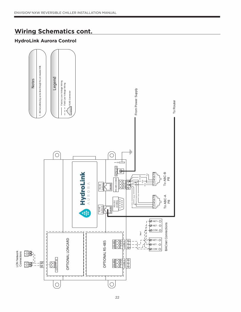
HydroLink Aurora Control
1234
5678
To A
BC-A
P
8To
AB
C-B
P8
RS-
485
CO
M2
RJ-
45(L
AN
1)
RJ-
45(L
AN
2) RS-
232
(CO
M1)
WPM
15V
s+
-
Op
on C
ard
Slot
#2
Op
on C
ard
Slot
#1
OPT
ION
AL
RS-4
85
CO
M 3
RS-
485
CO
M 4
RS-
485
OPT
ION
AL
LON
CARD
LON
FTT
-10
-+
S-
+S
BA
Cne
t Con
nect
ions
NET+
NET-
COM
NET+
NET-
COM
12LO
N N
etw
ork
Con
nect
ions
To R
oute
r
From
Pow
er S
uppl
y
1234
5678
Lege
ndFa
ctor
y Lo
w V
olta
ge W
iring
Fiel
d Lo
w V
olta
ge W
iring
1234
5678
RJ4
5 C
onne
ctor
Whi
teB
lack
Ora
nge R
ed
Whi
te
Ora
nge
Bla
ck
Red
Not
es
1 – B
ACne
t add
ress
ing c
an be
done
throu
gh th
e unit
mou
nted
HMI
.
12
Note
1
23
ENVISION2 NXW REVERSIBLE CHILLER INSTALLATION MANUAL
TB Typical AquaStat
24VAC
24V COM
Comp 1
Comp 2
Rev Valve
Acc 2
Acc 1
Alarm
Circuit 1 Alarm
Circuit 2 Alarm
24VAC
24V COM
Comp 1
Comp 2
Rev Valve
Accessory Item 1
R
C
Y1
Y2
O/B
X2
X1
L
LC1
LC2
R
C
Y1
Y2
B
NOTES: 1) Acc Output 1 is cycled with the lead compressor 2) Acc Output 2 is cycled with the lag compressor
Unit Power Supply208-230/60/3,
460/60/3, or 575/60/3
G L3 L1L2PB
Black
Red
White
Black
White
Red
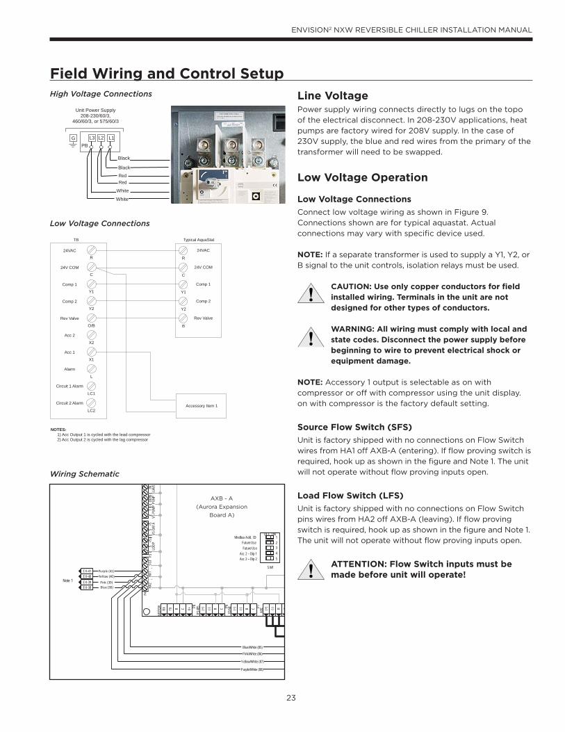
Field Wiring and Control SetupHigh Voltage Connections
Low Voltage Connections
Line VoltagePower supply wiring connects directly to lugs on the topo
of the electrical disconnect. In 208-230V applications, heat
pumps are factory wired for 208V supply. In the case of
230V supply, the blue and red wires from the primary of the
transformer will need to be swapped.
Low Voltage Operation
Low Voltage Connections
Connect low voltage wiring as shown in Figure 9.
Connections shown are for typical aquastat. Actual
connections may vary with specific device used.
NOTE: If a separate transformer is used to supply a Y1, Y2, or
B signal to the unit controls, isolation relays must be used.
CAUTION: Use only copper conductors for field installed wiring. Terminals in the unit are not designed for other types of conductors.
WARNING: All wiring must comply with local and state codes. Disconnect the power supply before beginning to wire to prevent electrical shock or equipment damage.
NOTE: Accessory 1 output is selectable as on with
compressor or off with compressor using the unit display.
on with compressor is the factory default setting.
Source Flow Switch (SFS)
Unit is factory shipped with no connections on Flow Switch
wires from HA1 off AXB-A (entering). If flow proving switch is
required, hook up as shown in the figure and Note 1. The unit
will not operate without flow proving inputs open.
Load Flow Switch (LFS)
Unit is factory shipped with no connections on Flow Switch
pins wires from HA2 off AXB-A (leaving). If flow proving
switch is required, hook up as shown in the figure and Note 1.
The unit will not operate without flow proving inputs open.
ATTENTION: Flow Switch inputs must be made before unit will operate!
Wiring Schematic
P8
MOT
OR P6
RS48
5 P7
ZONE
ABCCR(-)(+) CR(-)(+) CR(-)(+)
P4HA
2HA
1SG
ILO
OP
VSDA
TAVS
PUM
PPU
MPSL
AVE
P3
V+CRTXRX
SW1
Modbus Add. IDFuture Use
12345
ONOFF
Future UseAcc 2 – Dip 1Acc 2 – Dip 2
CS
+5C
CC
21
INOU
T+5
S
EX-41EX-40EX-39EX-38 Blue (38)
Pink (39)
Yellow (40)
Purple (41)
Blue/White (85)
Yellow/White (87)
Pink/White (86)
Purple/White (88)
Note 1
AXB - A
(Aurora Expansion
Board A)
24
ENVISION2 NXW REVERSIBLE CHILLER INSTALLATION MANUAL
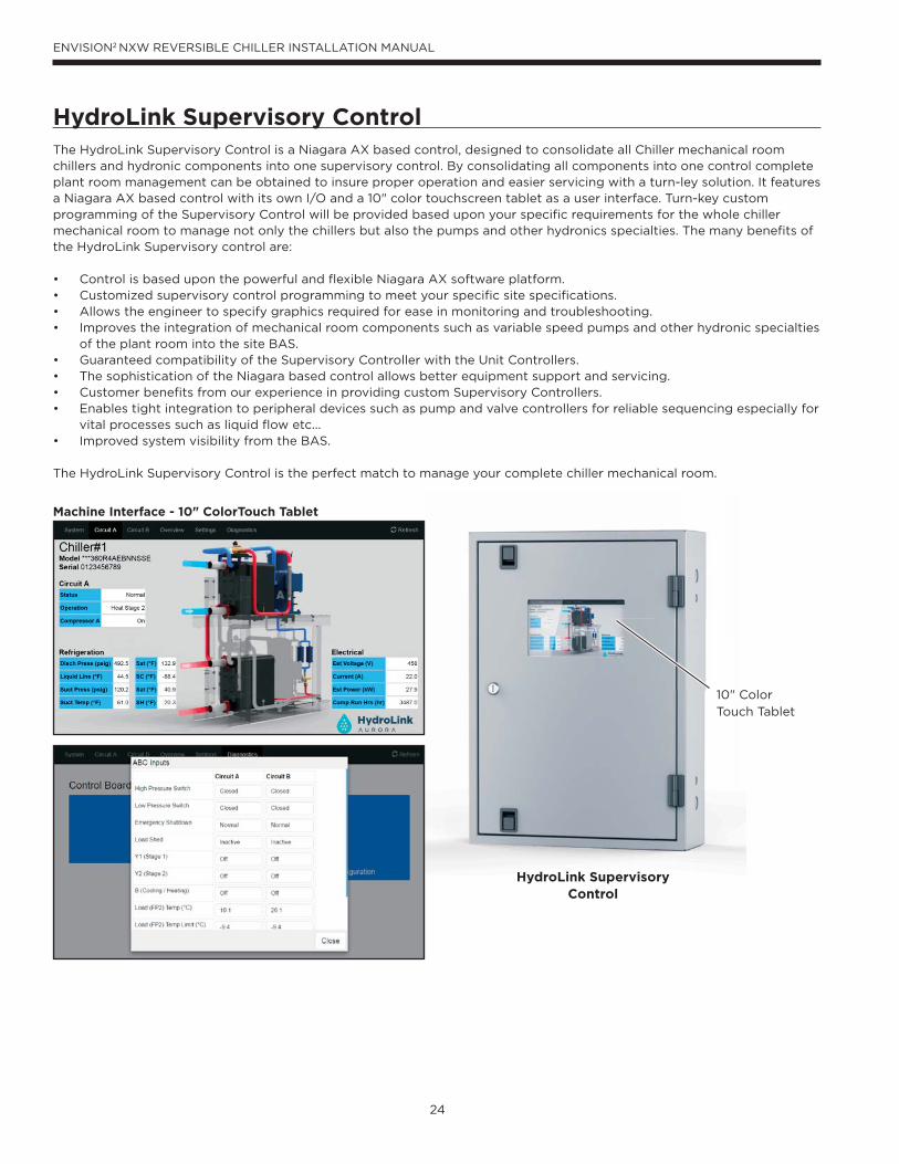
HydroLink Supervisory ControlThe HydroLink Supervisory Control is a Niagara AX based control, designed to consolidate all Chiller mechanical room chillers and hydronic components into one supervisory control. By consolidating all components into one control complete plant room management can be obtained to insure proper operation and easier servicing with a turn-ley solution. It features a Niagara AX based control with its own I/O and a 10" color touchscreen tablet as a user interface. Turn-key custom programming of the Supervisory Control will be provided based upon your specifi c requirements for the whole chiller mechanical room to manage not only the chillers but also the pumps and other hydronics specialties. The many benefi ts of the HydroLink Supervisory control are:
• Control is based upon the powerful and fl exible Niagara AX software platform.• Customized supervisory control programming to meet your specifi c site specifi cations.• Allows the engineer to specify graphics required for ease in monitoring and troubleshooting.• Improves the integration of mechanical room components such as variable speed pumps and other hydronic specialties
of the plant room into the site BAS.• Guaranteed compatibility of the Supervisory Controller with the Unit Controllers.• The sophistication of the Niagara based control allows better equipment support and servicing.• Customer benefi ts from our experience in providing custom Supervisory Controllers.• Enables tight integration to peripheral devices such as pump and valve controllers for reliable sequencing especially for
vital processes such as liquid fl ow etc...• Improved system visibility from the BAS.
The HydroLink Supervisory Control is the perfect match to manage your complete chiller mechanical room.
Machine Interface - 10" ColorTouch Tablet
HydroLink Supervisory Control
10" Color
Touch Tablet
25
ENVISION2 NXW REVERSIBLE CHILLER INSTALLATION MANUAL
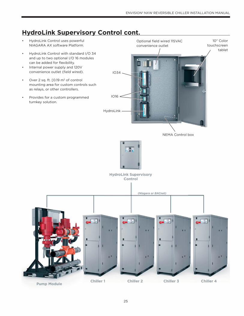
• HydroLink Control uses powerful
NIAGARA AX software Platform.
• HydroLink Control with standard I/O 34
and up to two optional I/O 16 modules
can be added for fl exibility.
• Internal power supply and 120V
convenience outlet (fi eld wired).
• Over 2 sq. ft. [0.19 m2 of control
mounting area for custom controls such
as relays, or other controllers.
• Provides for a custom programmed
turnkey solution.
HydroLink Supervisory Control cont.Optional field wired 115VAC
convenience outlet
IO34
IO16
HydroLink
NEMA Control box
10" Color
touchscreen
tablet
26
ENVISION2 NXW REVERSIBLE CHILLER INSTALLATION MANUAL
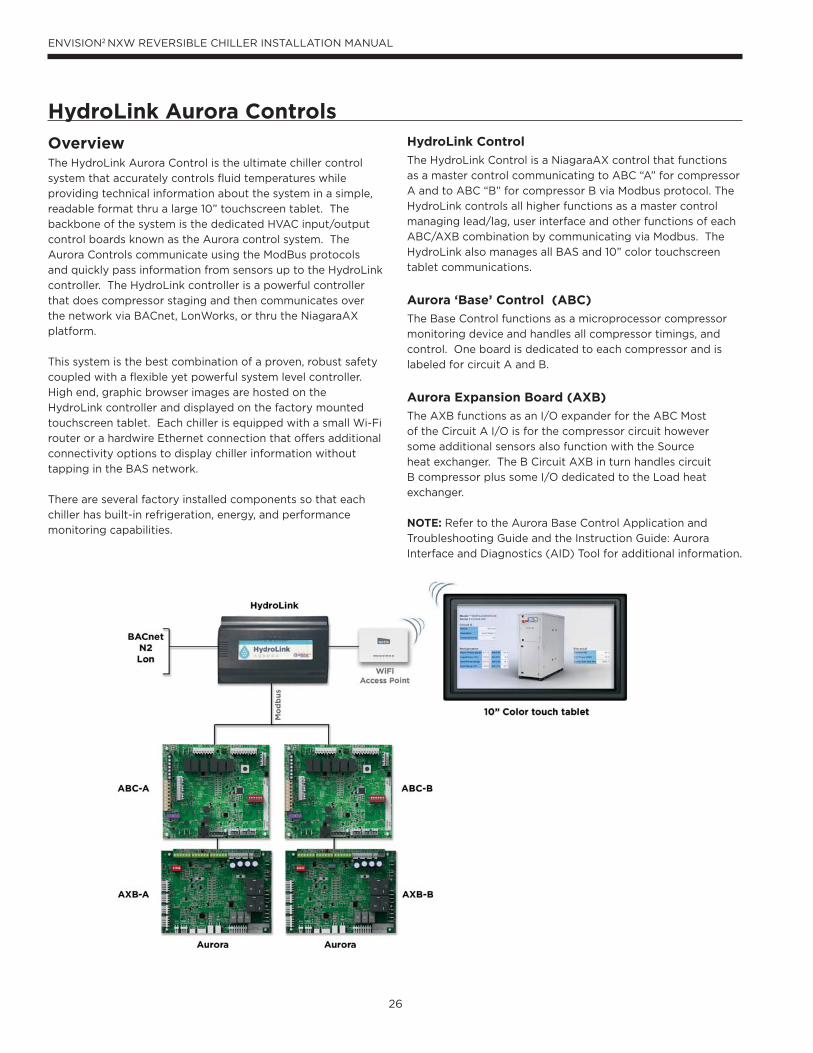
HydroLink Aurora Controls
OverviewThe HydroLink Aurora Control is the ultimate chiller control
system that accurately controls fluid temperatures while
providing technical information about the system in a simple,
readable format thru a large 10” touchscreen tablet. The
backbone of the system is the dedicated HVAC input/output
control boards known as the Aurora control system. The
Aurora Controls communicate using the ModBus protocols
and quickly pass information from sensors up to the HydroLink
controller. The HydroLink controller is a powerful controller
that does compressor staging and then communicates over
the network via BACnet, LonWorks, or thru the NiagaraAX
platform.
This system is the best combination of a proven, robust safety
coupled with a flexible yet powerful system level controller.
High end, graphic browser images are hosted on the
HydroLink controller and displayed on the factory mounted
touchscreen tablet. Each chiller is equipped with a small Wi-Fi
router or a hardwire Ethernet connection that offers additional
connectivity options to display chiller information without
tapping in the BAS network.
There are several factory installed components so that each
chiller has built-in refrigeration, energy, and performance
monitoring capabilities.
HydroLink Control
The HydroLink Control is a NiagaraAX control that functions
as a master control communicating to ABC “A” for compressor
A and to ABC “B” for compressor B via Modbus protocol. The
HydroLink controls all higher functions as a master control
managing lead/lag, user interface and other functions of each
ABC/AXB combination by communicating via Modbus. The
HydroLink also manages all BAS and 10” color touchscreen
tablet communications.
Aurora ‘Base’ Control (ABC)
The Base Control functions as a microprocessor compressor
monitoring device and handles all compressor timings, and
control. One board is dedicated to each compressor and is
labeled for circuit A and B.
Aurora Expansion Board (AXB)
The AXB functions as an I/O expander for the ABC Most
of the Circuit A I/O is for the compressor circuit however
some additional sensors also function with the Source
heat exchanger. The B Circuit AXB in turn handles circuit
B compressor plus some I/O dedicated to the Load heat
exchanger.
NOTE: Refer to the Aurora Base Control Application and
Troubleshooting Guide and the Instruction Guide: Aurora
Interface and Diagnostics (AID) Tool for additional information.
27
ENVISION2 NXW REVERSIBLE CHILLER INSTALLATION MANUAL
HydroLink Aurora Controls cont.
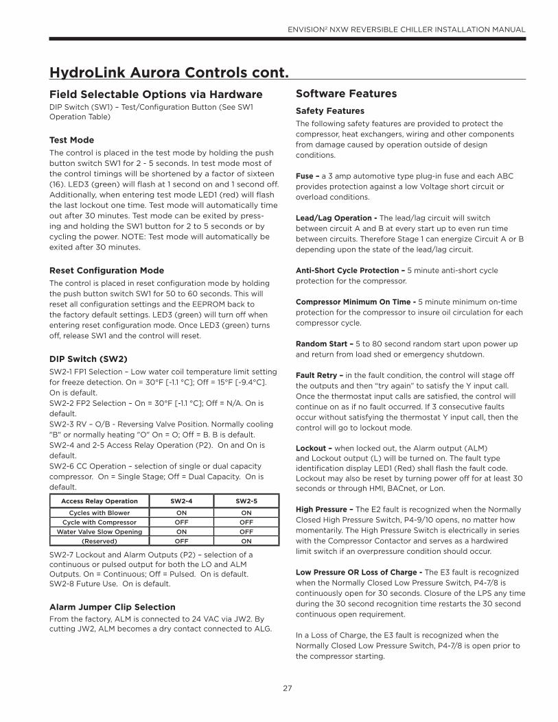
Field Selectable Options via Hardware DIP Switch (SW1) – Test/Configuration Button (See SW1 Operation Table)
Test Mode
The control is placed in the test mode by holding the push
button switch SW1 for 2 - 5 seconds. In test mode most of
the control timings will be shortened by a factor of sixteen
(16). LED3 (green) will flash at 1 second on and 1 second off.
Additionally, when entering test mode LED1 (red) will flash
the last lockout one time. Test mode will automatically time
out after 30 minutes. Test mode can be exited by press-
ing and holding the SW1 button for 2 to 5 seconds or by
cycling the power. NOTE: Test mode will automatically be
exited after 30 minutes.
Reset Configuration Mode
The control is placed in reset configuration mode by holding
the push button switch SW1 for 50 to 60 seconds. This will
reset all configuration settings and the EEPROM back to
the factory default settings. LED3 (green) will turn off when
entering reset configuration mode. Once LED3 (green) turns
off, release SW1 and the control will reset.
DIP Switch (SW2)
SW2-1 FP1 Selection – Low water coil temperature limit setting
for freeze detection. On = 30°F [-1.1 °C]; Off = 15°F [-9.4°C].
On is default.
SW2-2 FP2 Selection – On = 30°F [-1.1 °C]; Off = N/A. On is
default.
SW2-3 RV – O/B - Reversing Valve Position. Normally cooling
"B" or normally heating "O" On = O; Off = B. B is default.
SW2-4 and 2-5 Access Relay Operation (P2). On and On is
default.
SW2-6 CC Operation – selection of single or dual capacity
compressor. On = Single Stage; Off = Dual Capacity. On is
default.
SW2-7 Lockout and Alarm Outputs (P2) – selection of a continuous or pulsed output for both the LO and ALM Outputs. On = Continuous; Off = Pulsed. On is default.SW2-8 Future Use. On is default.
Alarm Jumper Clip SelectionFrom the factory, ALM is connected to 24 VAC via JW2. By cutting JW2, ALM becomes a dry contact connected to ALG.
Access Relay Operation SW2-4 SW2-5
Cycles with Blower ON ON
Cycle with Compressor OFF OFF
Water Valve Slow Opening ON OFF
(Reserved) OFF ON
Software Features
Safety Features
The following safety features are provided to protect the
compressor, heat exchangers, wiring and other components
from damage caused by operation outside of design
conditions.
Fuse – a 3 amp automotive type plug-in fuse and each ABC
provides protection against a low Voltage short circuit or
overload conditions.
Lead/Lag Operation - The lead/lag circuit will switch
between circuit A and B at every start up to even run time
between circuits. Therefore Stage 1 can energize Circuit A or B
depending upon the state of the lead/lag circuit.
Anti-Short Cycle Protection – 5 minute anti-short cycle
protection for the compressor.
Compressor Minimum On Time - 5 minute minimum on-time
protection for the compressor to insure oil circulation for each
compressor cycle.
Random Start – 5 to 80 second random start upon power up
and return from load shed or emergency shutdown.
Fault Retry – in the fault condition, the control will stage off
the outputs and then “try again” to satisfy the Y input call.
Once the thermostat input calls are satisfied, the control will
continue on as if no fault occurred. If 3 consecutive faults
occur without satisfying the thermostat Y input call, then the
control will go to lockout mode.
Lockout – when locked out, the Alarm output (ALM) and Lockout output (L) will be turned on. The fault type identification display LED1 (Red) shall flash the fault code. Lockout may also be reset by turning power off for at least 30 seconds or through HMI, BACnet, or Lon.
High Pressure – The E2 fault is recognized when the Normally
Closed High Pressure Switch, P4-9/10 opens, no matter how
momentarily. The High Pressure Switch is electrically in series
with the Compressor Contactor and serves as a hardwired
limit switch if an overpressure condition should occur.
Low Pressure OR Loss of Charge - The E3 fault is recognized
when the Normally Closed Low Pressure Switch, P4-7/8 is
continuously open for 30 seconds. Closure of the LPS any time
during the 30 second recognition time restarts the 30 second
continuous open requirement.
In a Loss of Charge, the E3 fault is recognized when the
Normally Closed Low Pressure Switch, P4-7/8 is open prior to
the compressor starting.

28
ENVISION2 NXW REVERSIBLE CHILLER INSTALLATION MANUAL
Freeze Detection - Refrigerant (Source – E5 or Load HX E4) – Freeze detection can be triggered by either a
30 sec. recognition of the FP1 (Source HX) or FP2 (Load
HX) temperature OR a 30 sec recognition of saturation
temperature (using Suction pressure) below setpoint of 30
degrees. For the FP sensors, set points shall be either 30°F
[-1.1 °C] or 15°F [-9.4°C] for the refrigerant temperature (can
also be adjusted between these points). When the thermistor
temperature drops below the selected set point, the control
shall begin counting down the 30 seconds delay. If the
thermistor value rises above the selected set point, then the
count should reset. The resistance value must remain below
the selected set point for the entire length of the appropriate
delay to be recognized as a fault.
For the Saturation Temperature, the suction pressure sensor
is monitored and when the resulting saturation temperature
is below 30°F [-1.1°C] for 30 continuous seconds a fault is
triggered in a similar fashion. There is no indication which
condition has triggered the fault other than sensor readings at
the time of the event.
Water Temp Fault EST/ELT – HX fluid (Source or Load HX) – An E26 alarm can be triggered by a 30 sec. recognition of the
EST (Source or Load HX) temperature below specified limit.
An E27 alarm can be triggered by a 30 sec. recognition of the
EST (Source or Load HX) temperature above specified limit.
It is recommended that the Alarms be set 1-2 degrees off of
the Fault set points so that the Alarm will trigger first prior to
generating the faults or Lockouts.
Water Temp Fault LST/LLT – HX fluid (Source or Load HX) – An E28 alarm can be triggered by a 30 sec. recognition of the
EST (Source or Load HX) temperature below specified limit.
An E29 alarm can be triggered by a 30 sec. recognition of the
EST (Source or Load HX) temperature above specified limit.
It is recommended that the Alarms be set 1-2 degrees off of
the Fault set points so that the Alarm will trigger first prior to
generating the faults or Lockouts.
Over/Under Voltage Shutdown - An over/under voltage
condition exists when the control voltage is outside the range
of 18 VAC to 30 VAC. If the over/under voltage shutdown lasts
for 15 minutes, the lockout and alarm relay will be energized.
Over/under voltage shutdown is self-resetting in that if the
voltage comes back within range of 18 VAC to 30 VAC for at
least 0.5 seconds, then normal operation is restored.
HydroLink Aurora Controls cont.
Operation DescriptionPower Up - The unit will not operate until all the inputs and safety controls are checked for normal conditions. The unit has a 5 to 80 second random start delay at power up. Then the compressor has a 4 minute anti-short cycle delay after the
random start delay.
Standby - In standby mode, Y1, Y2, W, DH, and G are not
active. Input O/B may be active. The compressor will be off.
Heating Operation
This product generally utilizes a “B” reverse cycle selection of the O/B reversing valve operation. In all heating operations, the reversing valve directly tracks the B input. Thus, anytime the B input is present, the reversing valve will be energized for heating mode. This means a failure of the reversing valve will still allow cooling mode operation. The lead/lag circuit will switch between circuit A and B at every start up to even run time between circuits. Therefore Stage 1 can energize Circuit Aor B depending upon the state of the lead/lag circuit.
Dual Compressor Heating, 1st Stage (Stage 1, B) The stage 1 compressor will be staged to full capacity 20
seconds after Y1 input is received at ABC A.
Dual Compressor Heating, 2nd Stage (Stage 1, Stage 2, B) The stage 2 compressor will be engaged to full capacity 30 seconds after Y2 input is received at the ABC A board.
Cooling Operation
This product generally utilizes a “B” reverse cycle selection of the O/B reversing valve operation. In all cooling operations, the reversing valve inversely tracks the B input. Thus, anytime the B input is NOT present, the reversing valve will be de-energized for cooling mode. This means a failure of the reversing valve will still allow cooling mode operation. The lead/lag circuit will switch between circuit A and B at every start up to even run time between circuits. Therefore Stage 1 can energize Circuit A or B depending upon the state of the
lead/lag circuit.
Dual Compressor Heating, 1st Stage (Stage 1, B) - The stage 1
compressor will be staged to full capacity 20 seconds after Y1
input is received at the ABC A board.
Dual Compressor Heating, 2nd Stage (Stage 1, Stage 2, B) - The stage 2 compressor will be engaged to full capacity 30
seconds after Y2 input is received at the ABC A board.
Source HX Load HX
Entering TempLow Fault E26 E26High Fault E27 E27
Leaving TempLow Fault E28 E28High Fault E29 E29
29
ENVISION2 NXW REVERSIBLE CHILLER INSTALLATION MANUAL
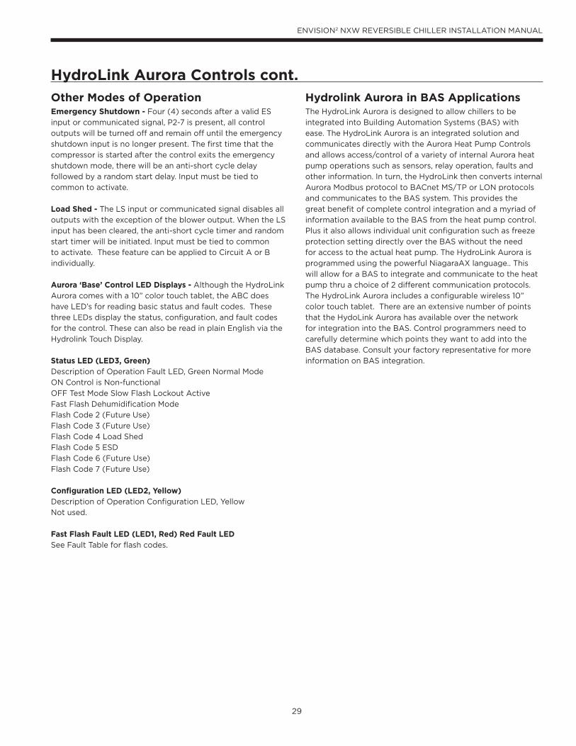
HydroLink Aurora Controls cont.
Other Modes of Operation Emergency Shutdown - Four (4) seconds after a valid ES
input or communicated signal, P2-7 is present, all control
outputs will be turned off and remain off until the emergency
shutdown input is no longer present. The first time that the
compressor is started after the control exits the emergency
shutdown mode, there will be an anti-short cycle delay
followed by a random start delay. Input must be tied to
common to activate.
Load Shed - The LS input or communicated signal disables all
outputs with the exception of the blower output. When the LS
input has been cleared, the anti-short cycle timer and random
start timer will be initiated. Input must be tied to common
to activate. These feature can be applied to Circuit A or B
individually.
Aurora ‘Base’ Control LED Displays - Although the HydroLink
Aurora comes with a 10” color touch tablet, the ABC does
have LED’s for reading basic status and fault codes. These
three LEDs display the status, configuration, and fault codes
for the control. These can also be read in plain English via the
Hydrolink Touch Display.
Status LED (LED3, Green) Description of Operation Fault LED, Green Normal Mode
ON Control is Non-functional
OFF Test Mode Slow Flash Lockout Active
Fast Flash Dehumidification Mode
Flash Code 2 (Future Use)
Flash Code 3 (Future Use)
Flash Code 4 Load Shed
Flash Code 5 ESD
Flash Code 6 (Future Use)
Flash Code 7 (Future Use)
Configuration LED (LED2, Yellow) Description of Operation Configuration LED, Yellow
Not used.
Fast Flash Fault LED (LED1, Red) Red Fault LED See Fault Table for flash codes.
Hydrolink Aurora in BAS ApplicationsThe HydroLink Aurora is designed to allow chillers to be
integrated into Building Automation Systems (BAS) with
ease. The HydroLink Aurora is an integrated solution and
communicates directly with the Aurora Heat Pump Controls
and allows access/control of a variety of internal Aurora heat
pump operations such as sensors, relay operation, faults and
other information. In turn, the HydroLink then converts internal
Aurora Modbus protocol to BACnet MS/TP or LON protocols
and communicates to the BAS system. This provides the
great benefit of complete control integration and a myriad of
information available to the BAS from the heat pump control.
Plus it also allows individual unit configuration such as freeze
protection setting directly over the BAS without the need
for access to the actual heat pump. The HydroLink Aurora is
programmed using the powerful NiagaraAX language.. This
will allow for a BAS to integrate and communicate to the heat
pump thru a choice of 2 different communication protocols.
The HydroLink Aurora includes a configurable wireless 10”
color touch tablet. There are an extensive number of points
that the HydoLink Aurora has available over the network
for integration into the BAS. Control programmers need to
carefully determine which points they want to add into the
BAS database. Consult your factory representative for more
information on BAS integration.

30
ENVISION2 NXW REVERSIBLE CHILLER INSTALLATION MANUAL
HydroLink Aurora Features • Built-in surge transient protection circuitry
• Operating range of -20° to 140°F [-28.9°C to 60°C]; 10 to
95% relative humidity, non-condensing • BACnet MS/TP• LonWorks TP/FT-10 (Requires optional LON plug-in
communication card) • Status of all unit operating conditions and fault lockouts • Visual color high definition display for status of power,
network communication, processor operation, and faults etc.
• Provides gateway into Aurora heat pump controls for unsurpassed control flexibility
• Network point for commanding unit into load shed • Network point for commanding unit into emergency
shutdown• Network points for freeze protection settings • Heating and cooling control from a remotely located
sensor • Wireless Local laptop browser connection for field service • FCC, UL and CE listed. BTL Certification
Advanced Features• AID Tool for Aurora ABC configuration and
troubleshooting.
• The display includes full color high definition graphics
display for easier diagnostics.
• Built-in 802.11g wi-fi router for wireless connectivity.
• The built in Aurora AXB expansion board and provides
added user I/O.
• Refrigeration Monitoring – provides Suction and discharge
pressure, Suction, liquid line temps and superheat and
subcooling.
• Energy Monitoring – provides real-time power
measurement (Watt) of compressor
• Performance Monitoring – provides entering and leaving
loop water temperatures, loop flow rate as well as heat
of extraction or rejection rate into the loop. (requires
optional field mounted flow meters.
HydroLink Aurora Touch Interface Utilizing a wireless 10” color touch-screen interface, the
HydroLink provides a technician the ability to configure and
diagnose equipment at the unit or wirelessly from any laptop
or tablet for added accessibility and simpler troubleshooting.
The technician will have full access to equipment status,
parameter values, temperature, and humidity sensing as
well as access to alarm and trend history. With website-like
navigation, the HydroLink Aurora Touch Interface is easy to
use and provides important insight into the system so your
building can operate as efficiently as possible
Available BAS Points
Nearly every internal input and output used in the control and
monitoring of the system is available as a point on the BAS
system. BACnet points list boasts nearly 100 points available
to the BAS system. Please consult the appropriate points list
for your specific network.
Compressor Proving Sensors – Are installed on each
compressor from the factory.
Fault, Configuration, and Status Codes – The codes can be
visible to the BAS if desired Fault LED (LED1, Red) Red Fault
LED
HydroLink Aurora Controls cont.
31
ENVISION2 NXW REVERSIBLE CHILLER INSTALLATION MANUAL
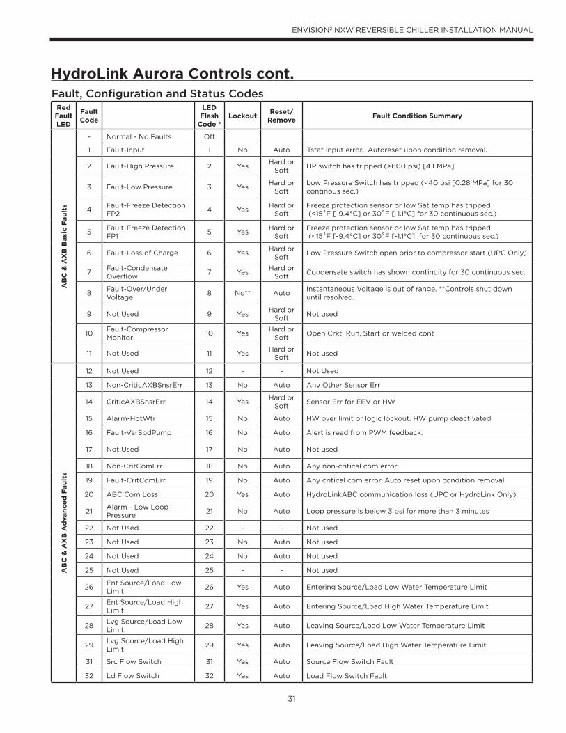
HydroLink Aurora Controls cont.Fault, Configuration and Status Codes
Red Fault LED
Fault Code
LED Flash
Code *Lockout
Reset/ Remove
Fault Condition Summary
AB
C &
AX
B B
asi
c F
au
lts
- Normal - No Faults Off
1 Fault-Input 1 No Auto Tstat input error. Autoreset upon condition removal.
2 Fault-High Pressure 2 YesHard or
SoftHP switch has tripped (>600 psi) [4.1 MPa]
3 Fault-Low Pressure 3 YesHard or
SoftLow Pressure Switch has tripped (<40 psi [0.28 MPa] for 30 continous sec.)
4Fault-Freeze Detection FP2
4 YesHard or
SoftFreeze protection sensor or low Sat temp has tripped (<15˚F [-9.4°C] or 30˚F [-1.1°C] for 30 continuous sec.)
5Fault-Freeze Detection FP1
5 YesHard or
SoftFreeze protection sensor or low Sat temp has tripped (<15˚F [-9.4°C] or 30˚F [-1.1°C] for 30 continuous sec.)
6 Fault-Loss of Charge 6 YesHard or
SoftLow Pressure Switch open prior to compressor start (UPC Only)
7Fault-Condensate Overflow
7 YesHard or
SoftCondensate switch has shown continuity for 30 continuous sec.
8Fault-Over/Under Voltage
8 No** AutoInstantaneous Voltage is out of range. **Controls shut down until resolved.
9 Not Used 9 YesHard or
SoftNot used
10Fault-Compressor Monitor
10 YesHard or
SoftOpen Crkt, Run, Start or welded cont
11 Not Used 11 YesHard or
SoftNot used
AB
C &
AX
B A
dvan
ce
d F
au
lts
12 Not Used 12 - - Not Used
13 Non-CriticAXBSnsrErr 13 No Auto Any Other Sensor Err
14 CriticAXBSnsrErr 14 YesHard or
SoftSensor Err for EEV or HW
15 Alarm-HotWtr 15 No Auto HW over limit or logic lockout. HW pump deactivated.
16 Fault-VarSpdPump 16 No Auto Alert is read from PWM feedback.
17 Not Used 17 No Auto Not used
18 Non-CritComErr 18 No Auto Any non-critical com error
19 Fault-CritComErr 19 No Auto Any critical com error. Auto reset upon condition removal
20 ABC Com Loss 20 Yes Auto HydroLinkABC communication loss (UPC or HydroLink Only)
21Alarm - Low Loop Pressure
21 No Auto Loop pressure is below 3 psi for more than 3 minutes
22 Not Used 22 - - Not used
23 Not Used 23 No Auto Not used
24 Not Used 24 No Auto Not used
25 Not Used 25 - - Not used
26Ent Source/Load Low Limit
26 Yes Auto Entering Source/Load Low Water Temperature Limit
27Ent Source/Load High Limit
27 Yes Auto Entering Source/Load High Water Temperature Limit
28Lvg Source/Load Low Limit
28 Yes Auto Leaving Source/Load Low Water Temperature Limit
29Lvg Source/Load High Limit
29 Yes Auto Leaving Source/Load High Water Temperature Limit
31 Src Flow Switch 31 Yes Auto Source Flow Switch Fault
32 Ld Flow Switch 32 Yes Auto Load Flow Switch Fault
32
ENVISION2 NXW REVERSIBLE CHILLER INSTALLATION MANUAL
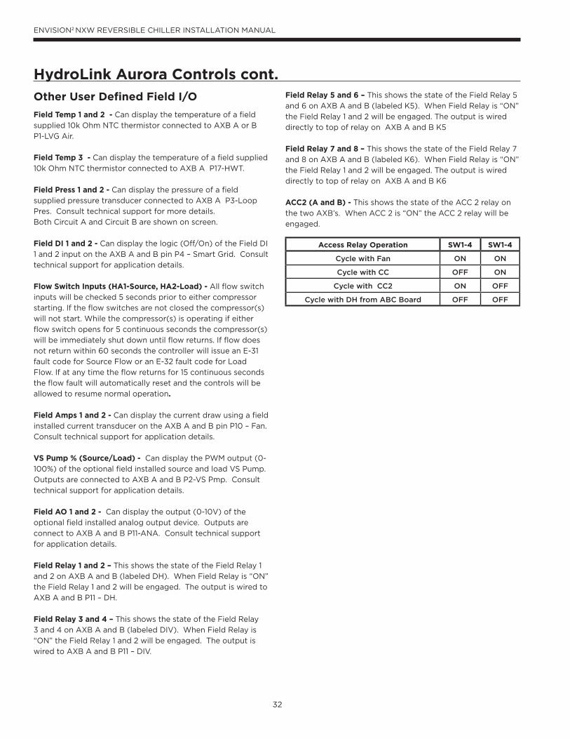
HydroLink Aurora Controls cont.Field Relay 5 and 6 – This shows the state of the Field Relay 5
and 6 on AXB A and B (labeled K5). When Field Relay is “ON”
the Field Relay 1 and 2 will be engaged. The output is wired
directly to top of relay on AXB A and B K5
Field Relay 7 and 8 – This shows the state of the Field Relay 7
and 8 on AXB A and B (labeled K6). When Field Relay is “ON”
the Field Relay 1 and 2 will be engaged. The output is wired
directly to top of relay on AXB A and B K6
ACC2 (A and B) - This shows the state of the ACC 2 relay on
the two AXB’s. When ACC 2 is “ON” the ACC 2 relay will be
engaged.
Other User Defined Field I/O
Field Temp 1 and 2 - Can display the temperature of a field
supplied 10k Ohm NTC thermistor connected to AXB A or B
P1-LVG Air.
Field Temp 3 - Can display the temperature of a field supplied
10k Ohm NTC thermistor connected to AXB A P17-HWT.
Field Press 1 and 2 - Can display the pressure of a field
supplied pressure transducer connected to AXB A P3-Loop
Pres. Consult technical support for more details.
Both Circuit A and Circuit B are shown on screen.
Field DI 1 and 2 - Can display the logic (Off/On) of the Field DI
1 and 2 input on the AXB A and B pin P4 – Smart Grid. Consult
technical support for application details.
Flow Switch Inputs (HA1-Source, HA2-Load) - All flow switch
inputs will be checked 5 seconds prior to either compressor
starting. If the flow switches are not closed the compressor(s)
will not start. While the compressor(s) is operating if either
flow switch opens for 5 continuous seconds the compressor(s)
will be immediately shut down until flow returns. If flow does
not return within 60 seconds the controller will issue an E-31
fault code for Source Flow or an E-32 fault code for Load
Flow. If at any time the flow returns for 15 continuous seconds
the flow fault will automatically reset and the controls will be
allowed to resume normal operation.
Field Amps 1 and 2 - Can display the current draw using a field
installed current transducer on the AXB A and B pin P10 – Fan.
Consult technical support for application details.
VS Pump % (Source/Load) - Can display the PWM output (0-
100%) of the optional field installed source and load VS Pump.
Outputs are connected to AXB A and B P2-VS Pmp. Consult
technical support for application details.
Field AO 1 and 2 - Can display the output (0-10V) of the
optional field installed analog output device. Outputs are
connect to AXB A and B P11-ANA. Consult technical support
for application details.
Field Relay 1 and 2 – This shows the state of the Field Relay 1
and 2 on AXB A and B (labeled DH). When Field Relay is “ON”
the Field Relay 1 and 2 will be engaged. The output is wired to
AXB A and B P11 – DH.
Field Relay 3 and 4 – This shows the state of the Field Relay
3 and 4 on AXB A and B (labeled DIV). When Field Relay is
“ON” the Field Relay 1 and 2 will be engaged. The output is
wired to AXB A and B P11 – DIV.
Access Relay Operation SW1-4 SW1-4
Cycle with Fan ON ON
Cycle with CC OFF ON
Cycle with CC2 ON OFF
Cycle with DH from ABC Board OFF OFF

33
ENVISION2 NXW REVERSIBLE CHILLER INSTALLATION MANUAL
Using the HydroLink Aurora Color Touch Tablet
Color Touch Tablet The Color Touch Tablet utilizes a touch-screen interface and HydroLink Aurora provides technicians with the ability to configure
and diagnose equipment at the unit or wirelessly from any laptop or tablet for added accessibility and simpler troubleshooting.
Technicians have full access to equipment status, parameter values, temperature, and humidity sensing as well as access to alarm
and trend history. With website-like navigation, the HydroLink Aurora Touch Interface is easy to use and provides important
insight into the system so your building can operate as efficiently as possible.

34
ENVISION2 NXW REVERSIBLE CHILLER INSTALLATION MANUAL
Using the HydroLink Aurora Color Touch Tablet cont.
System ScreenDisplays chiller status, operation, compressor status, source/load fluid temperatures, and control method. This screen gives an
overview of the chiller with ability to change the mode and set point condition directly from this screen.
- Indicates a variable that can be changed via a single tap on the text box area.
Status – “Normal” for normal operation or “Lockout” indicating the unit has locked out due to a fault. The “Fault” causing the
“Lockout” reason will be prominently displayed.
Operation – Displays the current operating condition of the unit such as “standby” or “cooling stage 2”
Compressor – Denotes the specific compressor that is operating. “A” for the top compressor circuit and “B” for the bottom. If
both are active, “A + B” will be displayed.
Mode – Since this product is a reversible chiller, this displays whether it is “Heating” or “Cooling”. In “Heating Mode” the source is
the evaporator and load is the Condenser, and in “Cooling Mode” it is reversed.
Method – Displays the control method current selected to operate the system. The three options include, Setpoint Control
using selectable onboard sensors and a PID loop, Aquastat mode using external (field supplied) 24V temperature sensor and
24VAC commands directly to the unit, Network Mode with operation commands directly thru BACnet/LON communication. See
Temperature Control Method Section for more detail.
Input – The selected temperature sensor for the control method.
Setpoint – The selected setpoint the unit is trying to maintain.
Control Temp – The current temperature of the control sensor.
Source Fluid: Leaving (°F) – The leaving source temperature in °F or °C.
Entering (°F) – The entering source temperature in °F or °C.
Flow – The source fluid flow in GPM or l/s
HE/HR – The source heat of extraction (heating mode) or rejection (cooling mode) in MBtuh or kW.
Load Fluid:
Leaving (°F) – The leaving load temperature in °F or °C.
Entering (°F) – The entering load temperature in °F or °C.
Flow – The load fluid flow in GPM or l/s
Capacity – The Load Capacity in MBtuh or kW.
NOTE: N/A – Is displayed in the “Flow”, “HE/HR”, and “Capacity” dialogue boxes when an optional field installed flow meter is not
connected to the HydroLink Aurora. Compatible flow meters must be used for accurate flow measurement. Consult your factory
representative for more information on this option.

35
ENVISION2 NXW REVERSIBLE CHILLER INSTALLATION MANUAL
Using the HydroLink Aurora Color Touch Tablet cont.
Circuit A/Circuit B ScreensAs the title suggests, these screen display information regarding the compressor circuit of interest. From this screen, refrigerant pressure and temperature values are displayed along with superheat, subcooling, and refrigerant saturation values. Compressor amperage, run hours, and estimated power are also displayed here. For information on “Est Power (kW)” please see “Diagnostics” section later in this manual.
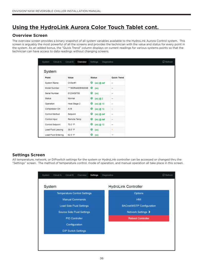
36
ENVISION2 NXW REVERSIBLE CHILLER INSTALLATION MANUAL
Using the HydroLink Aurora Color Touch Tablet cont.
Overview ScreenThe overview screen provides a binary snapshot of all system variables available to the HydroLink Aurora Control system. This screen is arguably the most powerful of all the screens and provides the technician with the value and status for every point in the system. As an added bonus, the “Quick Trend” column displays on current readings for various systems points so that the technician can have access to data readings without changing screens.
Settings Screen All temperature, network, or DIPswitch settings for the system or HydroLink controller can be accessed or changed thru the “Settings” screen. The method of temperature control, mode of operation, and manual operation all take place in this screen.
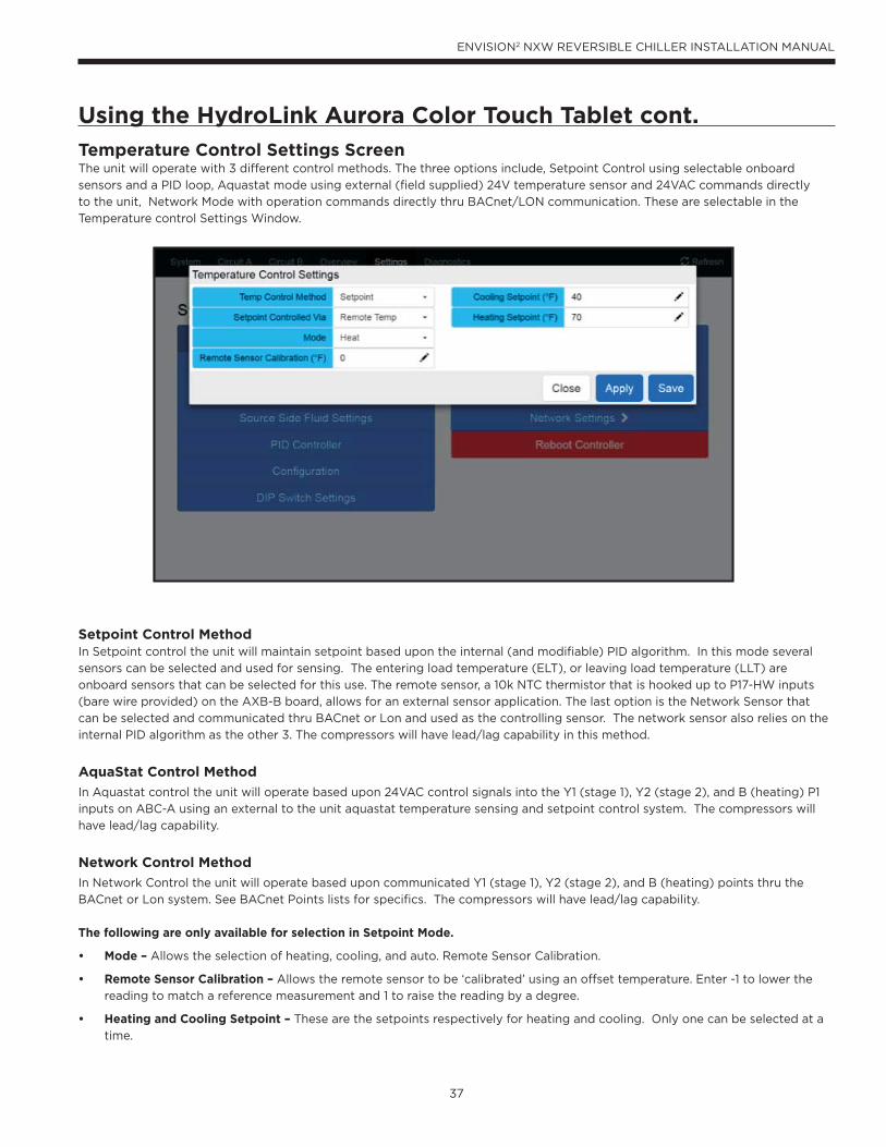
37
ENVISION2 NXW REVERSIBLE CHILLER INSTALLATION MANUAL
Using the HydroLink Aurora Color Touch Tablet cont.
Temperature Control Settings ScreenThe unit will operate with 3 different control methods. The three options include, Setpoint Control using selectable onboard
sensors and a PID loop, Aquastat mode using external (field supplied) 24V temperature sensor and 24VAC commands directly
to the unit, Network Mode with operation commands directly thru BACnet/LON communication. These are selectable in the
Temperature control Settings Window.
Setpoint Control MethodIn Setpoint control the unit will maintain setpoint based upon the internal (and modifiable) PID algorithm. In this mode several
sensors can be selected and used for sensing. The entering load temperature (ELT), or leaving load temperature (LLT) are
onboard sensors that can be selected for this use. The remote sensor, a 10k NTC thermistor that is hooked up to P17-HW inputs
(bare wire provided) on the AXB-B board, allows for an external sensor application. The last option is the Network Sensor that
can be selected and communicated thru BACnet or Lon and used as the controlling sensor. The network sensor also relies on the
internal PID algorithm as the other 3. The compressors will have lead/lag capability in this method.
AquaStat Control Method
In Aquastat control the unit will operate based upon 24VAC control signals into the Y1 (stage 1), Y2 (stage 2), and B (heating) P1
inputs on ABC-A using an external to the unit aquastat temperature sensing and setpoint control system. The compressors will
have lead/lag capability.
Network Control Method
In Network Control the unit will operate based upon communicated Y1 (stage 1), Y2 (stage 2), and B (heating) points thru the
BACnet or Lon system. See BACnet Points lists for specifics. The compressors will have lead/lag capability.
The following are only available for selection in Setpoint Mode.
• Mode – Allows the selection of heating, cooling, and auto. Remote Sensor Calibration.
• Remote Sensor Calibration – Allows the remote sensor to be ‘calibrated’ using an offset temperature. Enter -1 to lower the
reading to match a reference measurement and 1 to raise the reading by a degree.
• Heating and Cooling Setpoint – These are the setpoints respectively for heating and cooling. Only one can be selected at a
time.
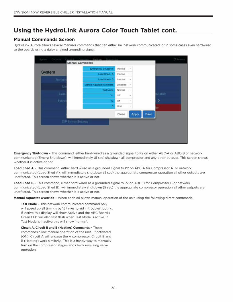
38
ENVISION2 NXW REVERSIBLE CHILLER INSTALLATION MANUAL
Using the HydroLink Aurora Color Touch Tablet cont.
Manual Commands ScreenHydroLink Aurora allows several manuals commands that can either be ‘network communicated’ or in some cases even hardwired
to the boards using a daisy chained grounding signal.
Emergency Shutdown – This command, either hard-wired as a grounded signal to P2 on either ABC-A or ABC-B or network
communicated (Emerg Shutdown), will immediately (5 sec) shutdown all compressor and any other outputs. This screen shows
whether it is active or not.
Load Shed A – This command, either hard wired as a grounded signal to P2 on ABC-A for Compressor A or network
communicated (Load Shed A), will immediately shutdown (5 sec) the appropriate compressor operation all other outputs are
unaffected. This screen shows whether it is active or not.
Load Shed B – This command, either hard wired as a grounded signal to P2 on ABC-B for Compressor B or network
communicated (Load Shed B), will immediately shutdown (5 sec) the appropriate compressor operation all other outputs are
unaffected. This screen shows whether it is active or not.
Manual Aquastat Override – When enabled allows manual operation of the unit using the following direct commands.
Test Mode – This network communicated command only
will speed up all timings by 16 times to aid in troubleshooting.
If Active this display will show Active and the ABC Board’s
Green LED will also fast flash when Test Mode is active. If
Test Mode is inactive this will show ‘normal’.
Circuit A, Circuit B and B (Heating) Commands – These
commands allow manual operation of the unit. If activated
(ON), Circuit A will engage the A compressor. Circuit B and
B (Heating) work similarly. This is a handy way to manually
turn on the compressor stages and check reversing valve
operation.
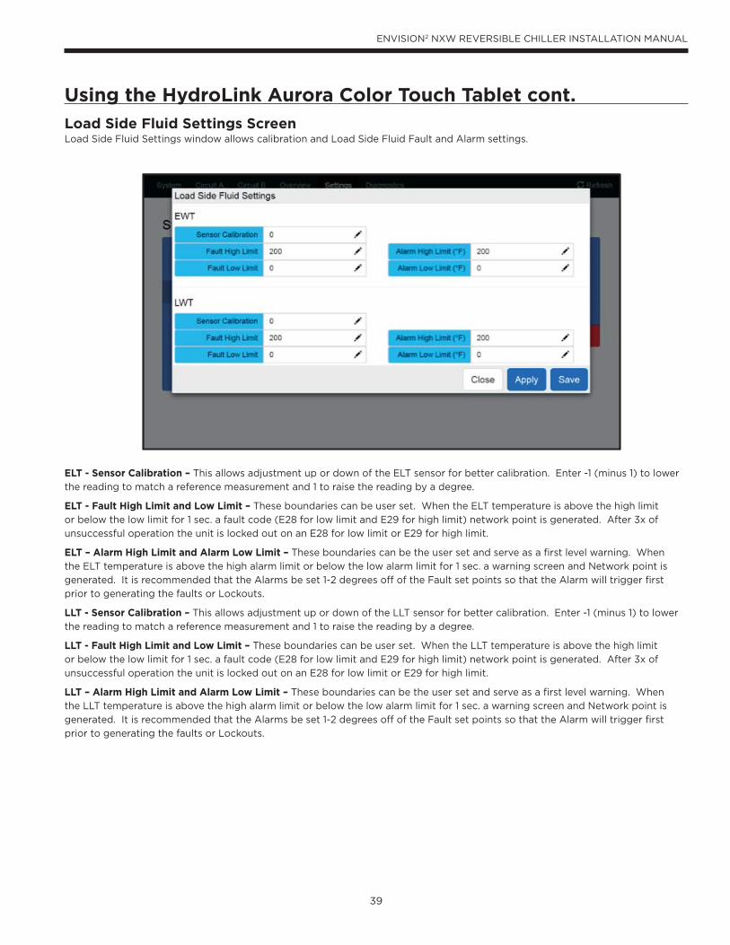
39
ENVISION2 NXW REVERSIBLE CHILLER INSTALLATION MANUAL
Using the HydroLink Aurora Color Touch Tablet cont.
Load Side Fluid Settings ScreenLoad Side Fluid Settings window allows calibration and Load Side Fluid Fault and Alarm settings.
ELT - Sensor Calibration – This allows adjustment up or down of the ELT sensor for better calibration. Enter -1 (minus 1) to lower
the reading to match a reference measurement and 1 to raise the reading by a degree.
ELT - Fault High Limit and Low Limit – These boundaries can be user set. When the ELT temperature is above the high limit
or below the low limit for 1 sec. a fault code (E28 for low limit and E29 for high limit) network point is generated. After 3x of
unsuccessful operation the unit is locked out on an E28 for low limit or E29 for high limit.
ELT – Alarm High Limit and Alarm Low Limit – These boundaries can be the user set and serve as a first level warning. When
the ELT temperature is above the high alarm limit or below the low alarm limit for 1 sec. a warning screen and Network point is
generated. It is recommended that the Alarms be set 1-2 degrees off of the Fault set points so that the Alarm will trigger first
prior to generating the faults or Lockouts.
LLT - Sensor Calibration – This allows adjustment up or down of the LLT sensor for better calibration. Enter -1 (minus 1) to lower
the reading to match a reference measurement and 1 to raise the reading by a degree.
LLT - Fault High Limit and Low Limit – These boundaries can be user set. When the LLT temperature is above the high limit
or below the low limit for 1 sec. a fault code (E28 for low limit and E29 for high limit) network point is generated. After 3x of
unsuccessful operation the unit is locked out on an E28 for low limit or E29 for high limit.
LLT – Alarm High Limit and Alarm Low Limit – These boundaries can be the user set and serve as a first level warning. When
the LLT temperature is above the high alarm limit or below the low alarm limit for 1 sec. a warning screen and Network point is
generated. It is recommended that the Alarms be set 1-2 degrees off of the Fault set points so that the Alarm will trigger first
prior to generating the faults or Lockouts.
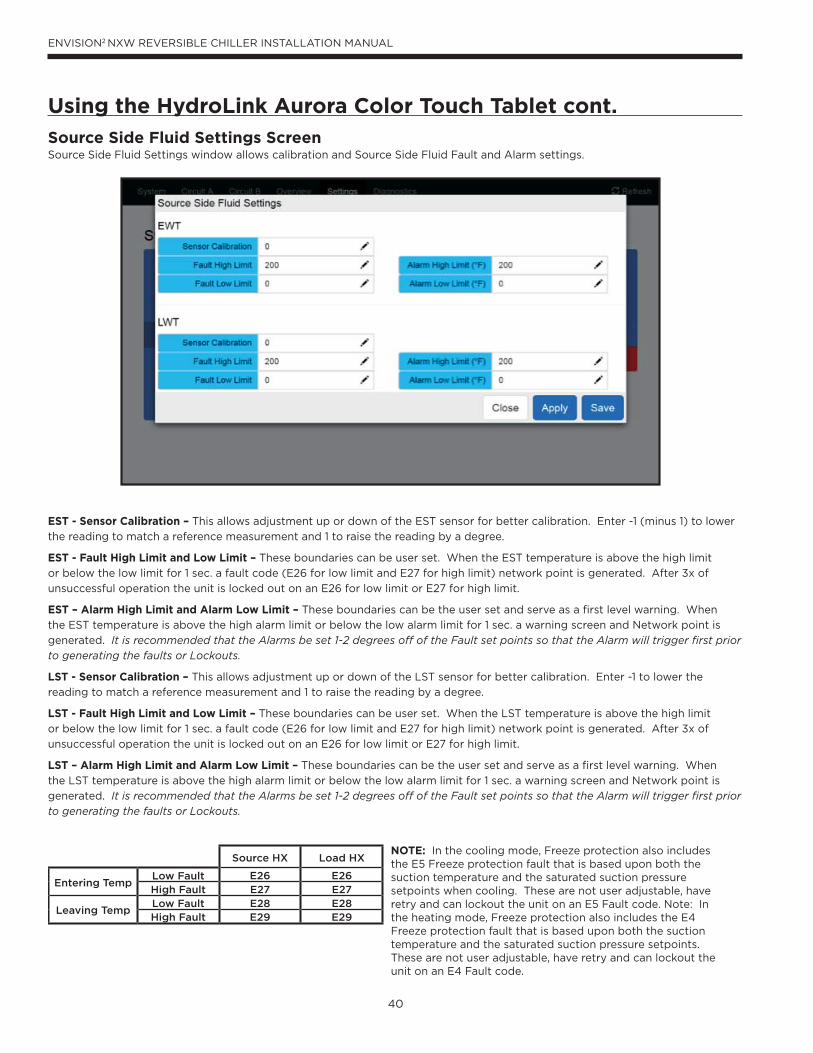
40
ENVISION2 NXW REVERSIBLE CHILLER INSTALLATION MANUAL
Using the HydroLink Aurora Color Touch Tablet cont.
Source Side Fluid Settings ScreenSource Side Fluid Settings window allows calibration and Source Side Fluid Fault and Alarm settings.
EST - Sensor Calibration – This allows adjustment up or down of the EST sensor for better calibration. Enter -1 (minus 1) to lower
the reading to match a reference measurement and 1 to raise the reading by a degree.
EST - Fault High Limit and Low Limit – These boundaries can be user set. When the EST temperature is above the high limit
or below the low limit for 1 sec. a fault code (E26 for low limit and E27 for high limit) network point is generated. After 3x of
unsuccessful operation the unit is locked out on an E26 for low limit or E27 for high limit.
EST – Alarm High Limit and Alarm Low Limit – These boundaries can be the user set and serve as a first level warning. When
the EST temperature is above the high alarm limit or below the low alarm limit for 1 sec. a warning screen and Network point is
generated. It is recommended that the Alarms be set 1-2 degrees off of the Fault set points so that the Alarm will trigger first prior to generating the faults or Lockouts.
LST - Sensor Calibration – This allows adjustment up or down of the LST sensor for better calibration. Enter -1 to lower the
reading to match a reference measurement and 1 to raise the reading by a degree.
LST - Fault High Limit and Low Limit – These boundaries can be user set. When the LST temperature is above the high limit
or below the low limit for 1 sec. a fault code (E26 for low limit and E27 for high limit) network point is generated. After 3x of
unsuccessful operation the unit is locked out on an E26 for low limit or E27 for high limit.
LST – Alarm High Limit and Alarm Low Limit – These boundaries can be the user set and serve as a first level warning. When
the LST temperature is above the high alarm limit or below the low alarm limit for 1 sec. a warning screen and Network point is
generated. It is recommended that the Alarms be set 1-2 degrees off of the Fault set points so that the Alarm will trigger first prior to generating the faults or Lockouts.
Source HX Load HX
Entering TempLow Fault E26 E26High Fault E27 E27
Leaving TempLow Fault E28 E28High Fault E29 E29
NOTE: In the cooling mode, Freeze protection also includes the E5 Freeze protection fault that is based upon both the suction temperature and the saturated suction pressure setpoints when cooling. These are not user adjustable, have retry and can lockout the unit on an E5 Fault code. Note: In the heating mode, Freeze protection also includes the E4 Freeze protection fault that is based upon both the suction temperature and the saturated suction pressure setpoints. These are not user adjustable, have retry and can lockout the unit on an E4 Fault code.
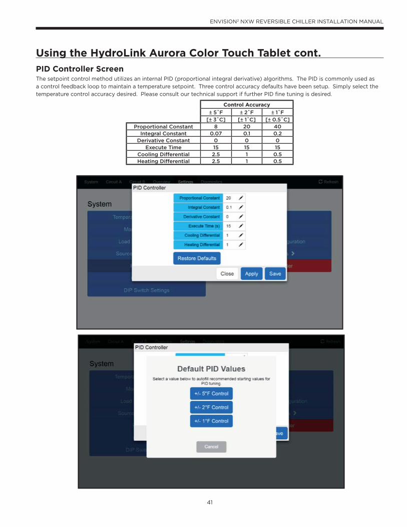
41
ENVISION2 NXW REVERSIBLE CHILLER INSTALLATION MANUAL
Using the HydroLink Aurora Color Touch Tablet cont.
PID Controller ScreenThe setpoint control method utilizes an internal PID (proportional integral derivative) algorithms. The PID is commonly used as
a control feedback loop to maintain a temperature setpoint. Three control accuracy defaults have been setup. Simply select the
temperature control accuracy desired. Please consult our technical support if further PID fine tuning is desired.
Control Accuracy
± 5˚F ± 2˚F ± 1˚F
[± 3˚C] [± 1˚C] [± 0.5˚C]Proportional Constant 8 20 40
Integral Constant 0.07 0.1 0.2Derivative Constant 0 0 0
Execute Time 15 15 15Cooling Differential 2.5 1 0.5Heating Differential 2.5 1 0.5
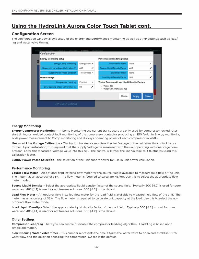
42
ENVISION2 NXW REVERSIBLE CHILLER INSTALLATION MANUAL
Using the HydroLink Aurora Color Touch Tablet cont.
Configuration ScreenThe configuration window allows setup of the energy and performance monitoring as well as other settings such as lead/
lag and water valve timing.
Energy Monitoring
Energy Compressor Monitoring – In Comp Monitoring the current transducers are only used for compressor locked rotor
start timing or welded contact fault monitoring of the compressor contactor producing an E10 fault. In Energy monitoring
adds power measurement to Comp monitoring and displays operating power of each compressor in Watts.
Measured Line Voltage Calibration – The HydroLink Aurora monitors the line Voltage of the unit after the control trans-
former. Upon installation, it is required that the supply Voltage be measured with the unit operating with one stage com-
pressor. Enter this measured Voltage value into this cell. The control will track the line Voltage as it fluctuates using this
calibration factor.
Supply Power Phase Selection – the selection of the unit supply power for use in unit power calculation.
Performance Monitoring
Source Flow Meter – An optional field installed flow meter for the source fluid is available to measure fluid flow of the unit.
The meter has an accuracy of ±3%. The flow meter is required to calculate HE/HR. Use this to select the appropriate flow
meter model.
Source Liquid Density – Select the appropriate liquid density factor of the source fluid. Typically 500 [4.2] is used for pure
water and 485 [4.1] is used for antifreezes solutions. 500 [4.2] is the default
Load Flow Meter – An optional field installed flow meter for the load fluid is available to measure fluid flow of the unit. The
meter has an accuracy of ±3%. The flow meter is required to calculate unit capacity at the load. Use this to select the ap-
propriate flow meter model.
Load Liquid Density – Select the appropriate liquid density factor of the load fluid. Typically 500 [4.2] is used for pure
water and 485 [4.1] is used for antifreezes solutions. 500 [4.2] is the default.
Other Settings
Compressor Lead/Lag – here you can enable or disable the compressor lead/lag algorithm. Lead/Lag is based upon
simple alternation.
Slow Opening Water Valve Timer – This number represents the time it takes the water valve to open and establish 100%
water flow and the delay on engaging the compressor. 60 sec is the default.
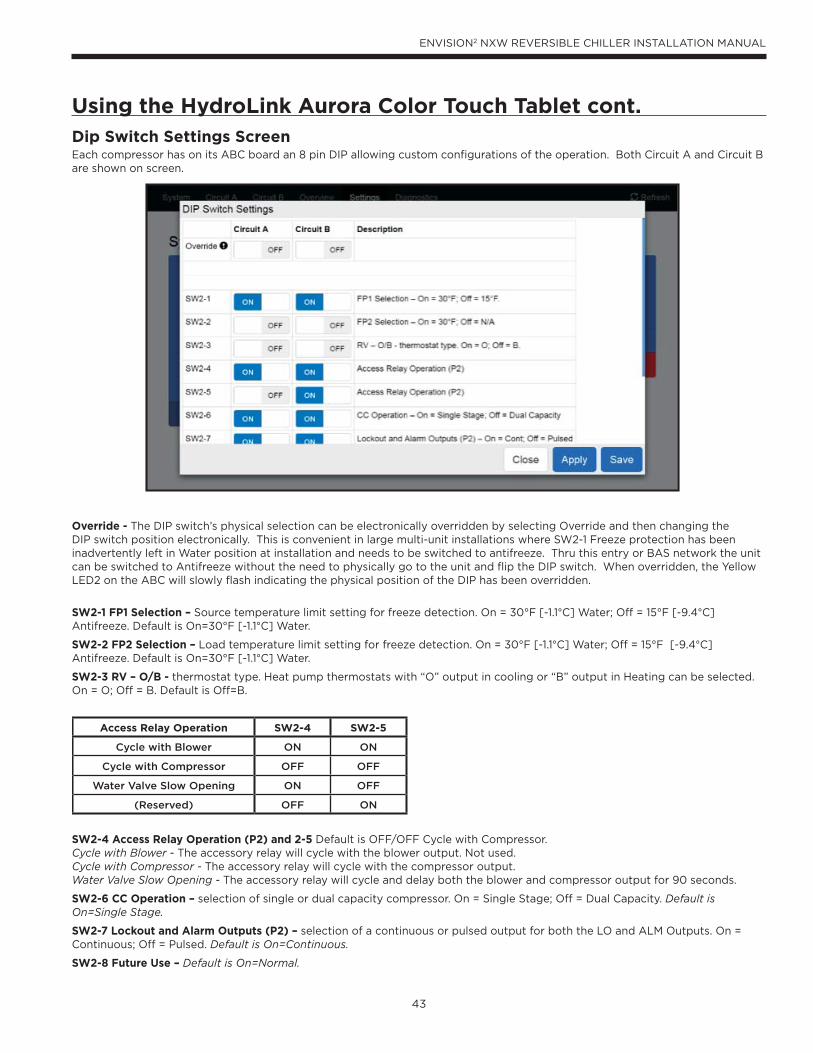
43
ENVISION2 NXW REVERSIBLE CHILLER INSTALLATION MANUAL
Access Relay Operation SW2-4 SW2-5
Cycle with Blower ON ON
Cycle with Compressor OFF OFF
Water Valve Slow Opening ON OFF
(Reserved) OFF ON
Using the HydroLink Aurora Color Touch Tablet cont.Dip Switch Settings ScreenEach compressor has on its ABC board an 8 pin DIP allowing custom configurations of the operation. Both Circuit A and Circuit B are shown on screen.
Override - The DIP switch’s physical selection can be electronically overridden by selecting Override and then changing the DIP switch position electronically. This is convenient in large multi-unit installations where SW2-1 Freeze protection has been inadvertently left in Water position at installation and needs to be switched to antifreeze. Thru this entry or BAS network the unit can be switched to Antifreeze without the need to physically go to the unit and flip the DIP switch. When overridden, the Yellow LED2 on the ABC will slowly flash indicating the physical position of the DIP has been overridden.
SW2-1 FP1 Selection – Source temperature limit setting for freeze detection. On = 30°F [-1.1°C] Water; Off = 15°F [-9.4°C] Antifreeze. Default is On=30°F [-1.1°C] Water.
SW2-2 FP2 Selection – Load temperature limit setting for freeze detection. On = 30°F [-1.1°C] Water; Off = 15°F [-9.4°C]Antifreeze. Default is On=30°F [-1.1°C] Water.
SW2-3 RV – O/B - thermostat type. Heat pump thermostats with “O” output in cooling or “B” output in Heating can be selected. On = O; Off = B. Default is Off=B.
SW2-4 Access Relay Operation (P2) and 2-5 Default is OFF/OFF Cycle with Compressor.Cycle with Blower - The accessory relay will cycle with the blower output. Not used.Cycle with Compressor - The accessory relay will cycle with the compressor output.Water Valve Slow Opening - The accessory relay will cycle and delay both the blower and compressor output for 90 seconds.
SW2-6 CC Operation – selection of single or dual capacity compressor. On = Single Stage; Off = Dual Capacity. Default is On=Single Stage.
SW2-7 Lockout and Alarm Outputs (P2) – selection of a continuous or pulsed output for both the LO and ALM Outputs. On = Continuous; Off = Pulsed. Default is On=Continuous.
SW2-8 Future Use – Default is On=Normal.
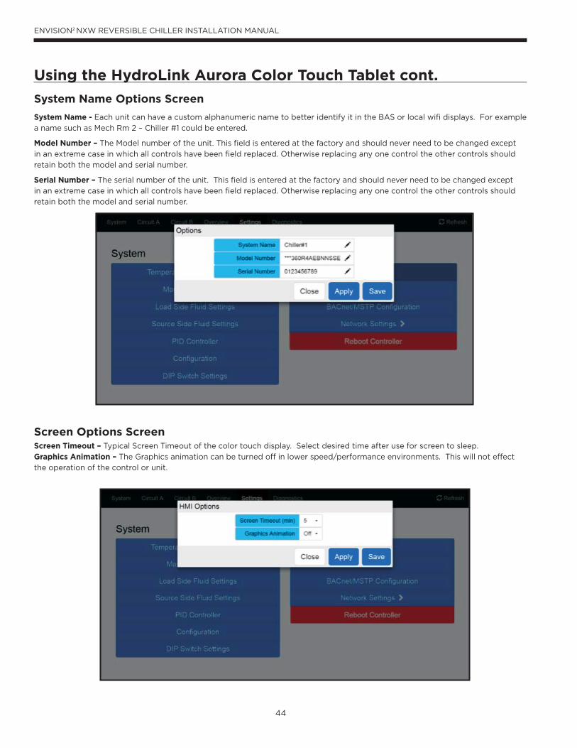
44
ENVISION2 NXW REVERSIBLE CHILLER INSTALLATION MANUAL
Using the HydroLink Aurora Color Touch Tablet cont.
System Name Options Screen
System Name - Each unit can have a custom alphanumeric name to better identify it in the BAS or local wifi displays. For example
a name such as Mech Rm 2 – Chiller #1 could be entered.
Model Number – The Model number of the unit. This field is entered at the factory and should never need to be changed except
in an extreme case in which all controls have been field replaced. Otherwise replacing any one control the other controls should
retain both the model and serial number.
Serial Number – The serial number of the unit. This field is entered at the factory and should never need to be changed except
in an extreme case in which all controls have been field replaced. Otherwise replacing any one control the other controls should
retain both the model and serial number.
Screen Options ScreenScreen Timeout – Typical Screen Timeout of the color touch display. Select desired time after use for screen to sleep.
Graphics Animation – The Graphics animation can be turned off in lower speed/performance environments. This will not effect
the operation of the control or unit.
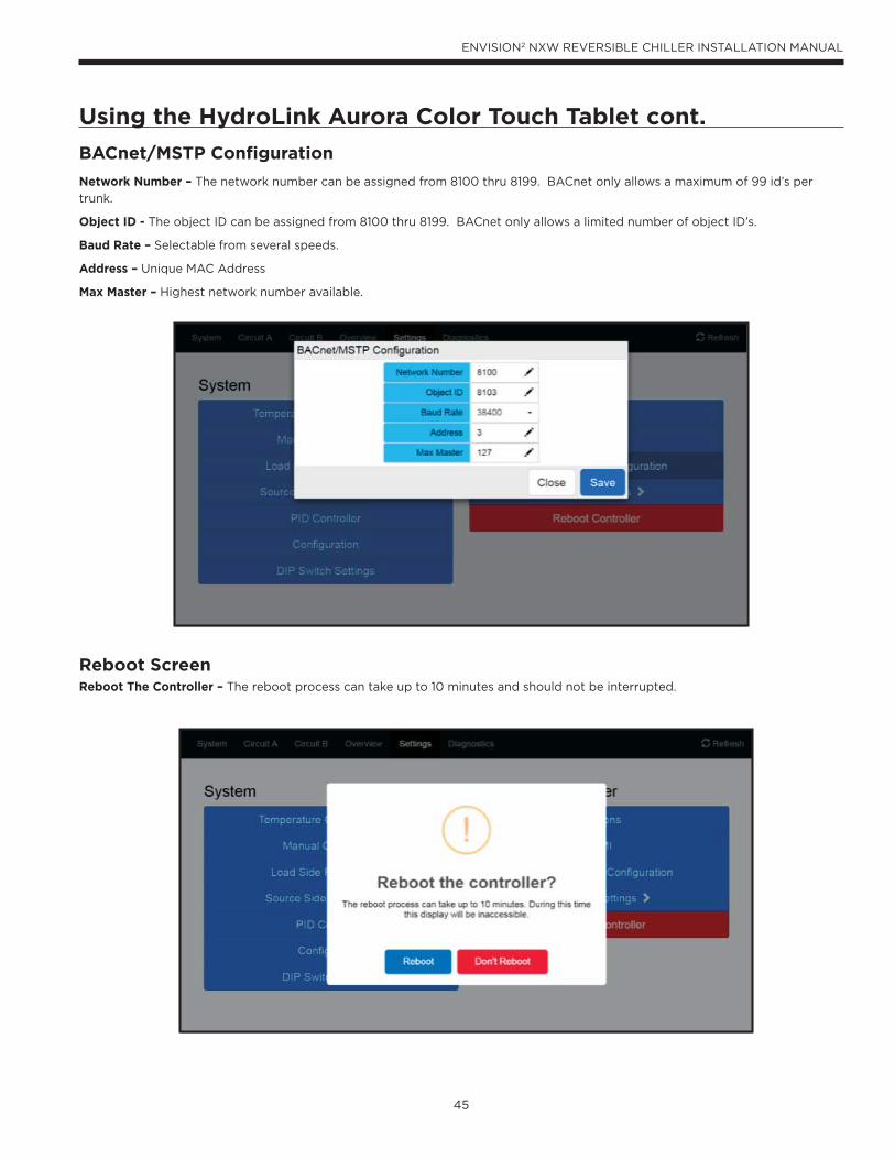
45
ENVISION2 NXW REVERSIBLE CHILLER INSTALLATION MANUAL
Using the HydroLink Aurora Color Touch Tablet cont.
BACnet/MSTP Configuration
Network Number – The network number can be assigned from 8100 thru 8199. BACnet only allows a maximum of 99 id’s per
trunk.
Object ID - The object ID can be assigned from 8100 thru 8199. BACnet only allows a limited number of object ID’s.
Baud Rate – Selectable from several speeds.
Address – Unique MAC Address
Max Master – Highest network number available.
Reboot ScreenReboot The Controller – The reboot process can take up to 10 minutes and should not be interrupted.
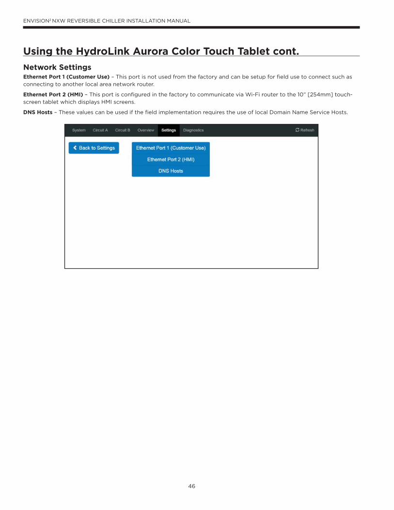
46
ENVISION2 NXW REVERSIBLE CHILLER INSTALLATION MANUAL
Using the HydroLink Aurora Color Touch Tablet cont.
Network SettingsEthernet Port 1 (Customer Use) – This port is not used from the factory and can be setup for field use to connect such as
connecting to another local area network router.
Ethernet Port 2 (HMI) – This port is configured in the factory to communicate via Wi-Fi router to the 10” [254mm] touch-
screen tablet which displays HMI screens.
DNS Hosts – These values can be used if the field implementation requires the use of local Domain Name Service Hosts.
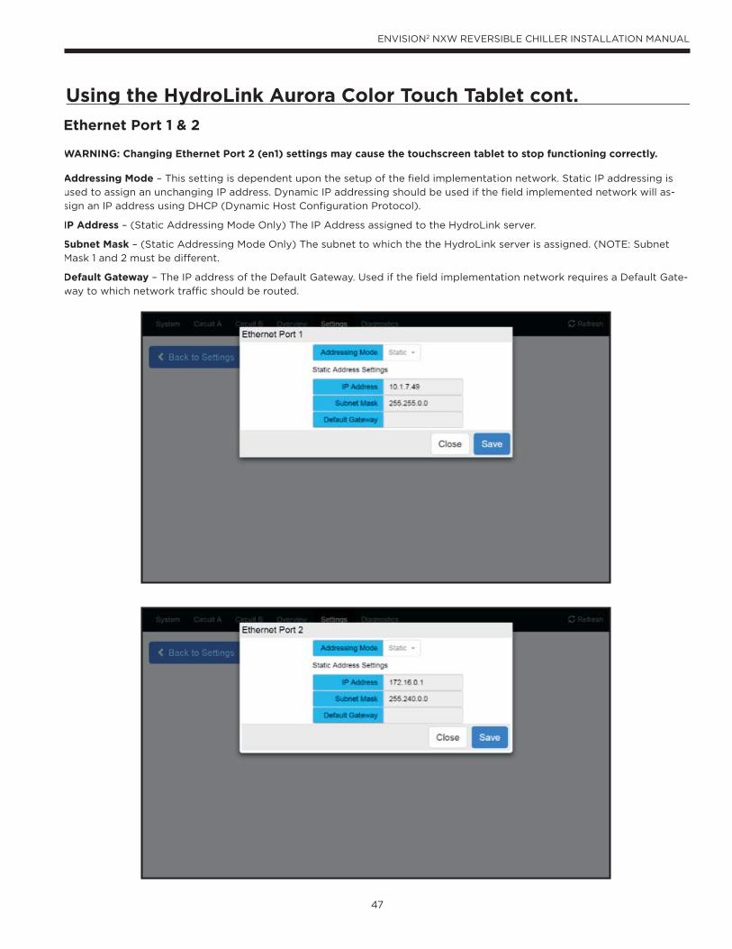
47
ENVISION2 NXW REVERSIBLE CHILLER INSTALLATION MANUAL
Using the HydroLink Aurora Color Touch Tablet cont.
Ethernet Port 1 & 2
WARNING: Changing Ethernet Port 2 (en1) settings may cause the touchscreen tablet to stop functioning correctly.
Addressing Mode – This setting is dependent upon the setup of the field implementation network. Static IP addressing is
used to assign an unchanging IP address. Dynamic IP addressing should be used if the field implemented network will as-
sign an IP address using DHCP (Dynamic Host Configuration Protocol).
IP Address – (Static Addressing Mode Only) The IP Address assigned to the HydroLink server.
Subnet Mask – (Static Addressing Mode Only) The subnet to which the the HydroLink server is assigned. (NOTE: Subnet
Mask 1 and 2 must be different.
Default Gateway – The IP address of the Default Gateway. Used if the field implementation network requires a Default Gate-
way to which network traffic should be routed.
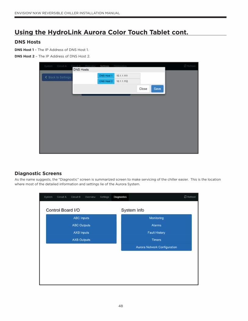
48
ENVISION2 NXW REVERSIBLE CHILLER INSTALLATION MANUAL
Using the HydroLink Aurora Color Touch Tablet cont.
DNS Hosts
DNS Host 1 – The IP Address of DNS Host 1.
DNS Host 2 – The IP Address of DNS Host 2.
Diagnostic ScreensAs the name suggests, the “Diagnostic” screen is summarized screen to make servicing of the chiller easier. This is the location
where most of the detailed information and settings lie of the Aurora System.
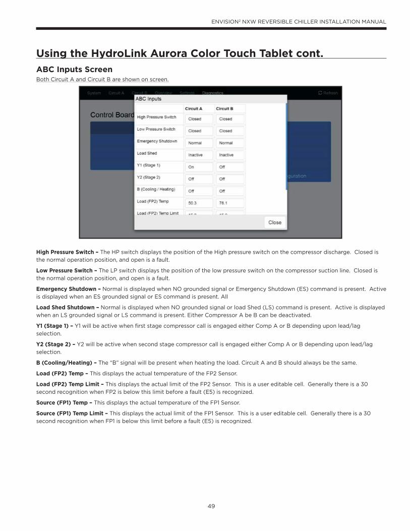
49
ENVISION2 NXW REVERSIBLE CHILLER INSTALLATION MANUAL
Using the HydroLink Aurora Color Touch Tablet cont.
ABC Inputs ScreenBoth Circuit A and Circuit B are shown on screen.
High Pressure Switch – The HP switch displays the position of the High pressure switch on the compressor discharge. Closed is
the normal operation position, and open is a fault.
Low Pressure Switch – The LP switch displays the position of the low pressure switch on the compressor suction line. Closed is
the normal operation position, and open is a fault.
Emergency Shutdown – Normal is displayed when NO grounded signal or Emergency Shutdown (ES) command is present. Active
is displayed when an ES grounded signal or ES command is present. All
Load Shed Shutdown – Normal is displayed when NO grounded signal or load Shed (LS) command is present. Active is displayed
when an LS grounded signal or LS command is present. Either Compressor A be B can be deactivated.
Y1 (Stage 1) – Y1 will be active when first stage compressor call is engaged either Comp A or B depending upon lead/lag
selection.
Y2 (Stage 2) – Y2 will be active when second stage compressor call is engaged either Comp A or B depending upon lead/lag
selection.
B (Cooling/Heating) – The “B” signal will be present when heating the load. Circuit A and B should always be the same.
Load (FP2) Temp – This displays the actual temperature of the FP2 Sensor.
Load (FP2) Temp Limit – This displays the actual limit of the FP2 Sensor. This is a user editable cell. Generally there is a 30
second recognition when FP2 is below this limit before a fault (E5) is recognized.
Source (FP1) Temp – This displays the actual temperature of the FP1 Sensor.
Source (FP1) Temp Limit – This displays the actual limit of the FP1 Sensor. This is a user editable cell. Generally there is a 30
second recognition when FP1 is below this limit before a fault (E5) is recognized.
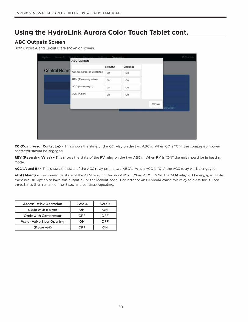
50
ENVISION2 NXW REVERSIBLE CHILLER INSTALLATION MANUAL
Using the HydroLink Aurora Color Touch Tablet cont.
ABC Outputs ScreenBoth Circuit A and Circuit B are shown on screen.
CC (Compressor Contactor) – This shows the state of the CC relay on the two ABC’s. When CC is “ON” the compressor power
contactor should be engaged.
REV (Reversing Valve) – This shows the state of the RV relay on the two ABC’s. When RV is “ON” the unit should be in heating
mode.
ACC (A and B) – This shows the state of the ACC relay on the two ABC’s. When ACC is “ON” the ACC relay will be engaged.
ALM (Alarm) – This shows the state of the ALM relay on the two ABC’s. When ALM is “ON” the ALM relay will be engaged. Note
there is a DIP option to have this output pulse the lockout code. For instance an E3 would cause this relay to close for 0.5 sec
three times then remain off for 2 sec. and continue repeating.
Access Relay Operation SW2-4 SW2-5
Cycle with Blower ON ON
Cycle with Compressor OFF OFF
Water Valve Slow Opening ON OFF
(Reserved) OFF ON
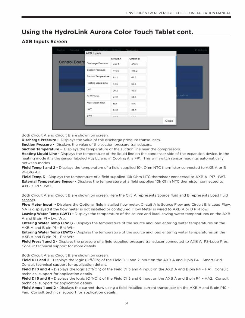
51
ENVISION2 NXW REVERSIBLE CHILLER INSTALLATION MANUAL
Using the HydroLink Aurora Color Touch Tablet cont.
AXB Inputs Screen
Both Circuit A and Circuit B are shown on screen.
Discharge Pressure - Displays the value of the discharge pressure transducers.
Suction Pressure - Displays the value of the suction pressure transducers.
Suction Temperature - Displays the temperature of the suction line near the compressors.
Heating Liquid Line - Displays the temperature of the liquid line on the condenser side of the expansion device. In the
heating mode it is the sensor labeled Htg LL and in Cooling it is FP1. This will switch sensor readings automatically
between modes.
Field Temp 1 and 2 - Displays the temperature of a field supplied 10k Ohm NTC thermistor connected to AXB A or B
P1-LVG Air.
Field Temp 3 - Displays the temperature of a field supplied 10k Ohm NTC thermistor connected to AXB A P17-HWT.
External Temperature Sensor - Displays the temperature of a field supplied 10k Ohm NTC thermistor connected to
AXB B P17-HWT.
Both Circuit A and Circuit B are shown on screen. Here the Circ A represents Source fluid and B represents Load fluid
sensors.
Flow Meter Input - Displays the Optional field installed flow meter. Circuit A is Source Flow and Circuit B is Load Flow.
NA is displayed if the flow meter is not installed or configured. Flow Meter is wired to AXB A or B P1-Flow.
Leaving Water Temp (LWT) - Displays the temperature of the source and load leaving water temperatures on the AXB
A and B pin P1 – Lvg Wtr.
Entering Water Temp (EWT) - Displays the temperature of the source and load entering water temperatures on the
AXB A and B pin P1 – Ent Wtr.
Entering Water Temp (EWT) - Displays the temperature of the source and load entering water temperatures on the
AXB A and B pin P1 – Ent Wtr.
Field Press 1 and 2 - Displays the pressure of a field supplied pressure transducer connected to AXB A P3-Loop Pres.
Consult technical support for more details.
Both Circuit A and Circuit B are shown on screen.
Field DI 1 and 2 - Displays the logic (Off/On) of the Field DI 1 and 2 input on the AXB A and B pin P4 – Smart Grid.
Consult technical support for application details.
Field DI 3 and 4 - Displays the logic (Off/On) of the Field DI 3 and 4 input on the AXB A and B pin P4 – HA1. Consult
technical support for application details.
Field DI 5 and 6 - Displays the logic (Off/On) of the Field DI 5 and 6 input on the AXB A and B pin P4 – HA2. Consult
technical support for application details.
Field Amps 1 and 2 - Displays the current draw using a field installed current transducer on the AXB A and B pin P10 –
Fan. Consult technical support for application details.
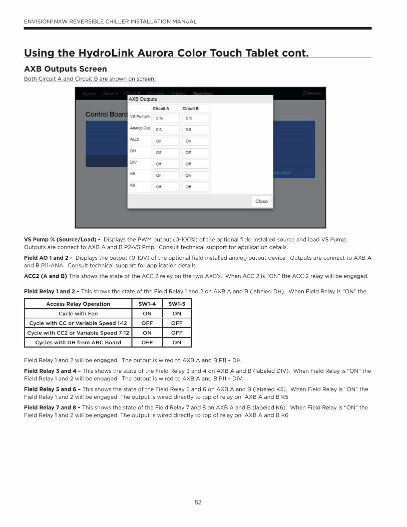
52
ENVISION2 NXW REVERSIBLE CHILLER INSTALLATION MANUAL
Using the HydroLink Aurora Color Touch Tablet cont.
AXB Outputs ScreenBoth Circuit A and Circuit B are shown on screen.
VS Pump % (Source/Load) - Displays the PWM output (0-100%) of the optional field installed source and load VS Pump.
Outputs are connect to AXB A and B P2-VS Pmp. Consult technical support for application details.
Field AO 1 and 2 - Displays the output (0-10V) of the optional field installed analog output device. Outputs are connect to AXB A
and B P11-ANA. Consult technical support for application details.
ACC2 (A and B) This shows the state of the ACC 2 relay on the two AXB’s. When ACC 2 is “ON” the ACC 2 relay will be engaged.
Field Relay 1 and 2 – This shows the state of the Field Relay 1 and 2 on AXB A and B (labeled DH). When Field Relay is “ON” the
Field Relay 1 and 2 will be engaged. The output is wired to AXB A and B P11 – DH.
Field Relay 3 and 4 – This shows the state of the Field Relay 3 and 4 on AXB A and B (labeled DIV). When Field Relay is “ON” the
Field Relay 1 and 2 will be engaged. The output is wired to AXB A and B P11 – DIV.
Field Relay 5 and 6 – This shows the state of the Field Relay 5 and 6 on AXB A and B (labeled K5). When Field Relay is “ON” the
Field Relay 1 and 2 will be engaged. The output is wired directly to top of relay on AXB A and B K5
Field Relay 7 and 8 – This shows the state of the Field Relay 7 and 8 on AXB A and B (labeled K6). When Field Relay is “ON” the
Field Relay 1 and 2 will be engaged. The output is wired directly to top of relay on AXB A and B K6
Access Relay Operation SW1-4 SW1-5
Cycle with Fan ON ON
Cycle with CC or Variable Speed 1-12 OFF OFF
Cycle with CC2 or Variable Speed 7-12 ON OFF
Cycles with DH from ABC Board OFF ON
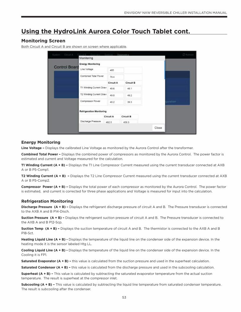
53
ENVISION2 NXW REVERSIBLE CHILLER INSTALLATION MANUAL
Using the HydroLink Aurora Color Touch Tablet cont.
Monitoring ScreenBoth Circuit A and Circuit B are shown on screen where applicable.
Energy Monitoring Line Voltage – Displays the calibrated Line Voltage as monitored by the Aurora Control after the transformer.
Combined Total Power – Displays the combined power of compressors as monitored by the Aurora Control. The power factor is
estimated and current and Voltage measured for the calculation.
T1 Winding Current (A + B) – Displays the T1 Line Compressor Current measured using the current transducer connected at AXB
A or B P5-Comp1.
T2 Winding Current (A + B) – Displays the T2 Line Compressor Current measured using the current transducer connected at AXB
A or B P5-Comp2.
Compressor Power (A + B) – Displays the total power of each compressor as monitored by the Aurora Control. The power factor
is estimated, and current is corrected for three phase applications and Voltage is measured for input into the calculation.
Refrigeration MonitoringDischarge Pressure (A + B) – Displays the refrigerant discharge pressure of circuit A and B. The Pressure transducer is connected
to the AXB A and B P14-Disch.
Suction Pressure (A + B) – Displays the refrigerant suction pressure of circuit A and B. The Pressure transducer is connected to
the AXB A and B P12-Scp.
Suction Temp (A + B) – Displays the suction temperature of circuit A and B. The thermistor is connected to the AXB A and B
P18-Sct.
Heating Liquid Line (A + B) - Displays the temperature of the liquid line on the condenser side of the expansion device. In the
heating mode it is the sensor labeled Htg LL.
Cooling Liquid Line (A + B) - Displays the temperature of the liquid line on the condenser side of the expansion device. In the
Cooling it is FP1.
Saturated Evaporator (A + B) – this value is calculated from the suction pressure and used in the superheat calculation.
Saturated Condenser (A + B) – this value is calculated from the discharge pressure and used in the subcooling calculation.
Superheat (A + B) – This value is calculated by subtracting the saturated evaporator temperature from the actual suction
temperature. The result is superheat at the compressor inlet.
Subcooling (A + B) – This value is calculated by subtracting the liquid line temperature from saturated condenser temperature.
The result is subcooling after the condenser.

54
ENVISION2 NXW REVERSIBLE CHILLER INSTALLATION MANUAL
Performance MonitoringBoth Circuit A and Circuit B are shown on screen.
Entering Source Temp (EST) - Displays the temperature of the source entering water temperatures on the AXB A pin P1 – Ent
Wtr.
Leaving Source Temp (LST) - Displays the temperature of the source leaving water temperatures on the AXB A pin P1 – Lvg Wtr.
Source Water Flow - Displays the Optional field installed flow meter. NA is displayed if the flow meter is not installed or
configured. Flow Meter is wired to AXB A P1-Flow.
Source Liquid Density – Displays the liquid density factor selected of the source fluid. Typically 500 [4.2] is used for pure water
and 485 [4.1] is used for antifreezes solutions.
Field Press 1 - Displays the pressure of a field supplied pressure transducer connected to AXB A P3-Loop Pres. Consult technical
support for more details.
Entering Load Temp (ELT) - Displays the temperature of the load entering water temperatures on the AXB B pin P1 – Ent Wtr.
Leaving Load Temp (LLT) - Displays the temperature of the load leaving water temperatures on the AXB B pin P1 – Lvg Wtr.
Load Water Flow - Displays the optional field installed flow meter. NA is displayed if the flow meter is not installed or configured.
Flow Meter is wired to AXB B P1-Flow.
Load Liquid Density – Displays the liquid density factor selected of the load fluid. Typically 500 [4.2] is used for pure water and
485 4.1] is used for antifreezes solutions.
Field Press 2 - Displays the pressure of a field supplied pressure transducer connected to AXB B P3-Loop Pres. Consult technical
support for more details.
Heat of Extraction/Rejection – The source heat of extraction (heating mode) or rejection (cooling mode) in MBtuh or kW.
Total Capacity – The Load Capacity of both circuits in MBtuh or kW.
NOTE: N/A – Is displayed in the “Flow”, “HE/HR”, and “Capacity” dialogue boxes when an optional field installed flow meter is not
connected to the HydroLink Aurora. Compatible flow meters must be used
Using the HydroLink Aurora Color Touch Tablet cont.
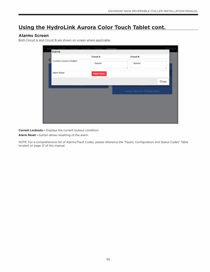
55
ENVISION2 NXW REVERSIBLE CHILLER INSTALLATION MANUAL
Using the HydroLink Aurora Color Touch Tablet cont.
Alarms ScreenBoth Circuit A and Circuit B are shown on screen where applicable.
Current Lockouts – Displays the current lockout condition.
Alarm Reset – button allows resetting of the alarm.
NOTE: For a comprehensive list of Alarms/Fault Codes, please reference the "Faults, Configuration and Status Codes" Table located on page 21 of this manual.
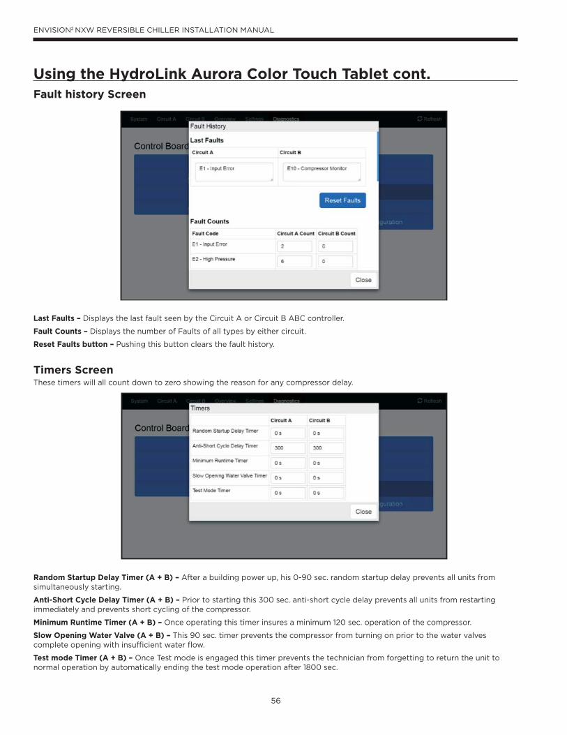
56
ENVISION2 NXW REVERSIBLE CHILLER INSTALLATION MANUAL
Fault history Screen
Last Faults – Displays the last fault seen by the Circuit A or Circuit B ABC controller.
Fault Counts – Displays the number of Faults of all types by either circuit.
Reset Faults button – Pushing this button clears the fault history.
Timers ScreenThese timers will all count down to zero showing the reason for any compressor delay.
Random Startup Delay Timer (A + B) – After a building power up, his 0-90 sec. random startup delay prevents all units from simultaneously starting.
Anti-Short Cycle Delay Timer (A + B) – Prior to starting this 300 sec. anti-short cycle delay prevents all units from restarting immediately and prevents short cycling of the compressor.
Minimum Runtime Timer (A + B) – Once operating this timer insures a minimum 120 sec. operation of the compressor.
Slow Opening Water Valve (A + B) – This 90 sec. timer prevents the compressor from turning on prior to the water valves complete opening with insufficient water flow.
Test mode Timer (A + B) – Once Test mode is engaged this timer prevents the technician from forgetting to return the unit to normal operation by automatically ending the test mode operation after 1800 sec.
Using the HydroLink Aurora Color Touch Tablet cont.
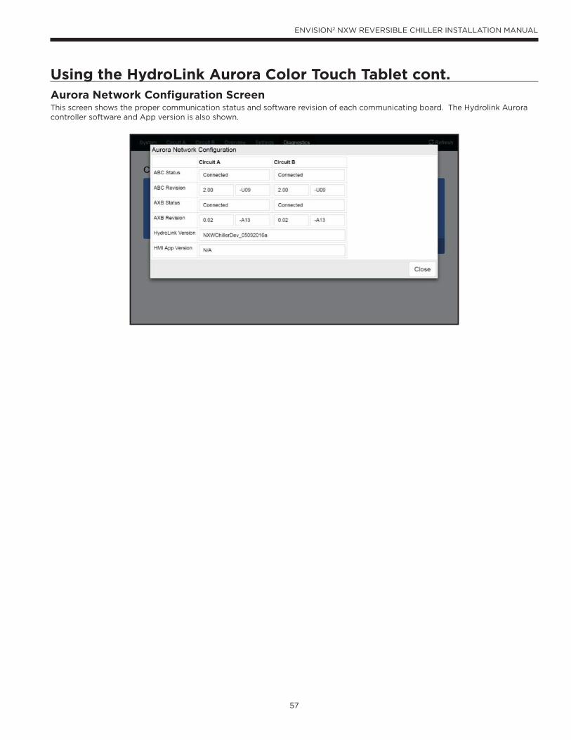
57
ENVISION2 NXW REVERSIBLE CHILLER INSTALLATION MANUAL
Using the HydroLink Aurora Color Touch Tablet cont.Aurora Network Configuration ScreenThis screen shows the proper communication status and software revision of each communicating board. The Hydrolink Aurora controller software and App version is also shown.
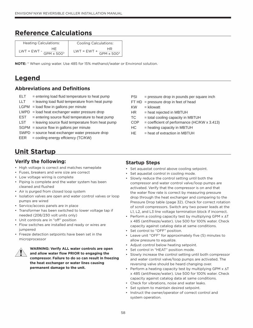
58
ENVISION2 NXW REVERSIBLE CHILLER INSTALLATION MANUAL
HE
GPM x 500*
Legend
Abbreviations and Definitions
Reference CalculationsHeating Calculations: Cooling Calculations:
LWT = EWT + HR
GPM x 500*LWT = EWT -
NOTE: * When using water. Use 485 for 15% methanol/water or Environol solution.
ELT = entering load fluid temperature to heat pump
EER = cooling energy effciency (TC/KW)
LLT = leaving load fluid temperature from heat pump
PSI = pressure drop in pounds per square inch
LGPM = load flow in gallons per minuteFT HD = pressure drop in feet of head
LWPD = load heat exchanger water pressure dropKW = kilowatt
EST = entering source fluid temperature to heat pump
HR = heat rejected in MBTUH
LST = leaving source fluid temperature from heat pumpTC = total cooling capacity in MBTUH
SGPM = source flow in gallons per minuteCOP = coefficient of performance (HC/KW x 3.413)
SWPD = source heat exchanger water pressure dropHC = heating capacity in MBTUHHE = heat of extraction in MBTUH
Verify the following:• High voltage is correct and matches nameplate
• Fuses, breakers and wire size are correct
• Low voltage wiring is complete
• Piping is complete and the water system has been
cleaned and flushed
• Air is purged from closed loop system
• Isolation valves are open and water control valves or loop
pumps are wired
• Service/access panels are in place
• Transformer has been switched to lower voltage tap if
needed (208/230 volt units only)
• Unit controls are in “off” position
• Flow switches are installed and ready or wires are
jumpered
• Freeze detection setpoints have been set in the
microprocessor
WARNING: Verify ALL water controls are open and allow water flow PRIOR to engaging the compressor. Failure to do so can result in freezing the heat exchanger or water lines causing permanent damage to the unit.
Unit Startup
Startup Steps• Set aquastat control above cooling setpoint.
• Set aquastat control in cooling mode.
• Slowly reduce the control setting until both the
compressor and water control valve/loop pumps are
activated. Verify that the compressor is on and that
the water flow rate is correct by measuring pressure
drop through the heat exchanger and comparing to the
Pressure Drop table (page 32). Check for correct rotation
of scroll compressors. Switch any two power leads at the
L1, L2, and L3 line voltage termination block if incorrect.
• Perform a cooling capacity test by multiplying GPM x ΔT
x 485 (antifreeze/water). Use 500 for 100% water. Check
capacity against catalog data at same conditions.
• Set control to “OFF” position.
• Leave unit “OFF” for approximately five (5) minutes to
allow pressure to equalize.
• Adjust control below heating setpoint.
• Set control in “HEAT” position mode.
• Slowly increase the control setting until both compressor
and water control valve/loop pumps are activated. The
reversing valve should be heard changing over.
• Perform a heating capacity test by multiplying GPM x ΔT
x 485 (antifreeze/water). Use 500 for 100% water. Check
capacity against catalog data at same conditions.
• Check for vibrations, noise and water leaks.
• Set system to maintain desired setpoint.
• Instruct the owner/operator of correct control and
system operation.
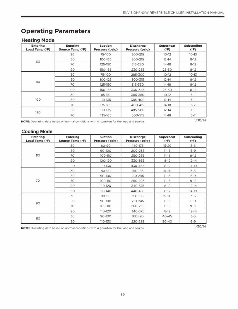
59
ENVISION2 NXW REVERSIBLE CHILLER INSTALLATION MANUAL
Operating Parameters
NOTE: Operating data based on normal conditions with 4 gpm/ton for the load and source.
NOTE: Operating data based on normal conditions with 4 gpm/ton for the load and source.
Heating ModeEntering
Load Temp (oF)Entering
Source Temp (oF)Suction
Pressure (psig)Discharge
Pressure (psig)Superheat
(oF)Subcooling
(oF)
60
30 75-100 200-215 10-12 10-13
50 100-125 200-215 12-14 8-12
70 125-150 215-230 14-18 8-12
90 150-165 230-255 25-30 8-12
80
30 75-100 285-300 10-12 10-13
50 100-125 300-315 12-14 8-12
70 125-150 315-330 14-18 8-12
90 150-165 330-345 25-30 8-12
100
30 85-110 365-380 10-12 7-11
50 110-135 385-400 12-14 7-11
70 135-165 400-415 14-18 3-7
12050 110-135 485-500 12-14 7-11
70 135-165 500-515 14-18 3-7
1/30/14
Cooling ModeEntering
Load Temp (oF)Entering
Source Temp (oF)Suction
Pressure (psig)Discharge
Pressure (psig)Superheat
(oF)Subcooling
(oF)
50
30 80-90 140-175 15-20 3-6
50 90-100 200-235 11-15 6-9
70 100-110 250-285 11-15 9-12
90 100-120 330-365 8-12 12-14
110 110-130 430-465 8-12 14-19
70
30 80-90 150-185 15-20 3-6
50 90-100 210-245 11-15 6-9
70 100-110 260-295 11-15 9-12
90 110-120 340-375 8-12 12-14
110 110-140 440-485 8-12 14-19
90
30 80-90 150-185 15-20 3-6
50 90-100 210-245 11-15 6-9
70 100-110 260-295 11-15 9-12
90 110-120 340-375 8-12 12-14
11030 90-100 160-195 40-45 3-6
50 110-130 220-255 30-40 6-9
1/30/14
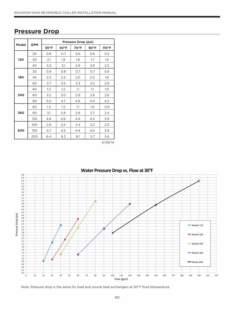
60
ENVISION2 NXW REVERSIBLE CHILLER INSTALLATION MANUAL
Pressure Drop
0.00.20.40.60.81.01.21.41.61.82.02.22.42.62.83.03.23.43.63.84.04.24.44.64.85.05.25.45.65.86.06.26.46.66.8
0 10 20 30 40 50 60 70 80 90 100 110 120 130 140 150 160 170 180 190 200 210 220
Pres
sure
Dro
p (p
si)
Flow (gpm)
Water Pressure Drop vs. Flow at 30°F
Model 120
Model 180
Model 240
Model 360
Model 600
Note: Pressure drop is the same for load and source heat exchangers at 30°F fluid temperature.
Model GPMPressure Drop (psi)
30°F 50°F 70°F 90°F 110°F
120
20 0.8 0.7 0.6 0.6 0.5
30 2.1 1.9 1.8 1.7 1.5
40 3.3 3.1 2.9 2.8 2.5
180
30 0.9 0.8 0.7 0.7 0.6
45 2.3 2.2 2.0 2.0 1.8
60 3.7 3.5 3.3 3.2 2.9
240
40 1.3 1.2 1.1 1.1 1.0
60 3.2 3.0 2.9 2.8 2.6
80 5.0 4.7 4.6 4.4 4.2
360
60 1.3 1.2 1.1 1.0 0.9
90 3.1 2.9 2.8 2.7 2.4
120 4.8 4.6 4.4 4.3 3.9
600
100 2.8 2.5 2.4 2.2 2.0
150 4.7 4.5 4.4 4.0 3.9
200 6.4 6.2 6.1 5.7 5.6
4/29/14
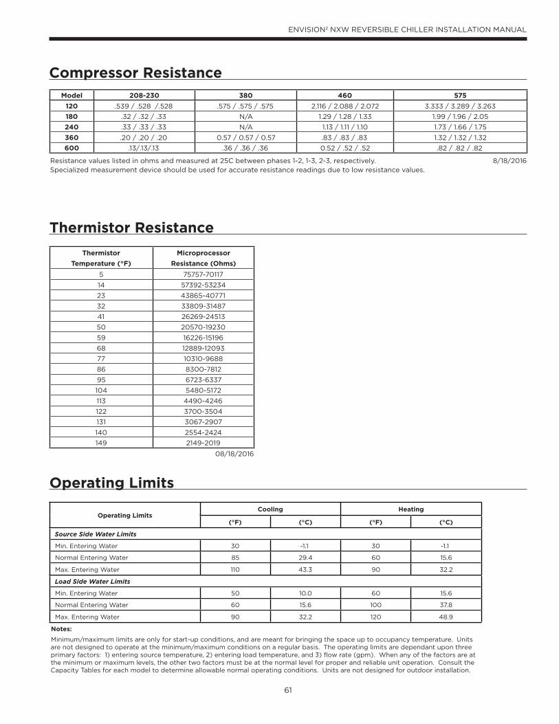
61
ENVISION2 NXW REVERSIBLE CHILLER INSTALLATION MANUAL
Compressor Resistance
Thermistor Resistance
Operating Limits
Operating LimitsCooling Heating
(°F) (°C) (°F) (°C)
Source Side Water Limits
Min. Entering Water 30 -1.1 30 -1.1
Normal Entering Water 85 29.4 60 15.6
Max. Entering Water 110 43.3 90 32.2
Load Side Water Limits
Min. Entering Water 50 10.0 60 15.6
Normal Entering Water 60 15.6 100 37.8
Max. Entering Water 90 32.2 120 48.9
Notes:
Minimum/maximum limits are only for start-up conditions, and are meant for bringing the space up to occupancy temperature. Units are not designed to operate at the minimum/maximum conditions on a regular basis. The operating limits are dependant upon three primary factors: 1) entering source temperature, 2) entering load temperature, and 3) flow rate (gpm). When any of the factors are at the minimum or maximum levels, the other two factors must be at the normal level for proper and reliable unit operation. Consult the Capacity Tables for each model to determine allowable normal operating conditions. Units are not designed for outdoor installation.
Model 208-230 380 460 575
120 .539 / .528 /.528 .575 / .575 / .575 2.116 / 2.088 / 2.072 3.333 / 3.289 / 3.263
180 .32 / .32 / .33 N/A 1.29 / 1.28 / 1.33 1.99 / 1.96 / 2.05
240 .33 / .33 / .33 N/A 1.13 / 1.11 / 1.10 1.73 / 1.66 / 1.75
360 .20 / .20 / .20 0.57 / 0.57 / 0.57 .83 / .83 / .83 1.32 / 1.32 / 1.32
600 .13/.13/.13 .36 / .36 / .36 0.52 / .52 / .52 .82 / .82 / .82
Resistance values listed in ohms and measured at 25C between phases 1-2, 1-3, 2-3, respectively. 8/18/2016Specialized measurement device should be used for accurate resistance readings due to low resistance values.
Thermistor
Temperature (°F)
Microprocessor
Resistance (Ohms)
5 75757-70117
14 57392-53234
23 43865-40771
32 33809-31487
41 26269-24513
50 20570-19230
59 16226-15196
68 12889-12093
77 10310-9688
86 8300-7812
95 6723-6337
104 5480-5172
113 4490-4246
122 3700-3504
131 3067-2907
140 2554-2424
149 2149-2019
08/18/2016
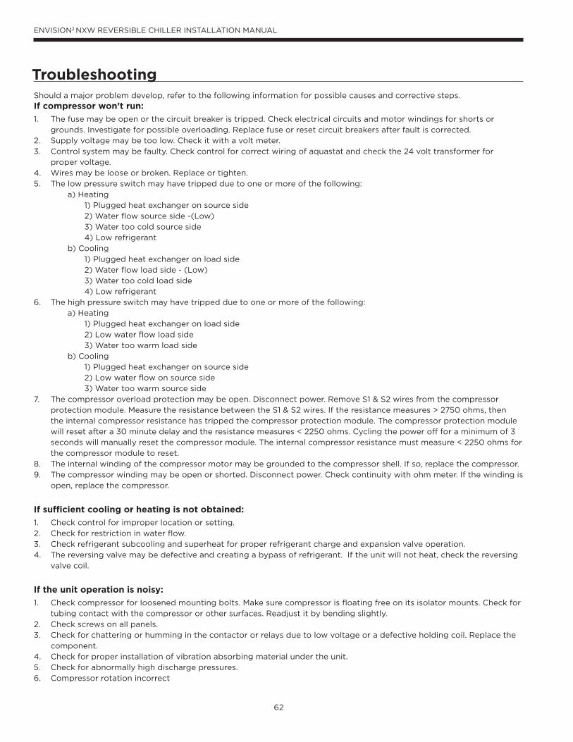
62
ENVISION2 NXW REVERSIBLE CHILLER INSTALLATION MANUAL
Should a major problem develop, refer to the following information for possible causes and corrective steps.
If compressor won’t run:
1. The fuse may be open or the circuit breaker is tripped. Check electrical circuits and motor windings for shorts or
grounds. Investigate for possible overloading. Replace fuse or reset circuit breakers after fault is corrected.
2. Supply voltage may be too low. Check it with a volt meter.
3. Control system may be faulty. Check control for correct wiring of aquastat and check the 24 volt transformer for
proper voltage.
4. Wires may be loose or broken. Replace or tighten.
5. The low pressure switch may have tripped due to one or more of the following:
a) Heating
1) Plugged heat exchanger on source side
2) Water flow source side -(Low)
3) Water too cold source side
4) Low refrigerant
b) Cooling
1) Plugged heat exchanger on load side
2) Water flow load side - (Low)
3) Water too cold load side
4) Low refrigerant
6. The high pressure switch may have tripped due to one or more of the following:
a) Heating
1) Plugged heat exchanger on load side
2) Low water flow load side
3) Water too warm load side
b) Cooling
1) Plugged heat exchanger on source side
2) Low water flow on source side
3) Water too warm source side
7. The compressor overload protection may be open. Disconnect power. Remove S1 & S2 wires from the compressor
protection module. Measure the resistance between the S1 & S2 wires. If the resistance measures > 2750 ohms, then
the internal compressor resistance has tripped the compressor protection module. The compressor protection module
will reset after a 30 minute delay and the resistance measures < 2250 ohms. Cycling the power off for a minimum of 3
seconds will manually reset the compressor module. The internal compressor resistance must measure < 2250 ohms for
the compressor module to reset.
8. The internal winding of the compressor motor may be grounded to the compressor shell. If so, replace the compressor.
9. The compressor winding may be open or shorted. Disconnect power. Check continuity with ohm meter. If the winding is
open, replace the compressor.
If sufficient cooling or heating is not obtained:
1. Check control for improper location or setting.
2. Check for restriction in water flow.
3. Check refrigerant subcooling and superheat for proper refrigerant charge and expansion valve operation.
4. The reversing valve may be defective and creating a bypass of refrigerant. If the unit will not heat, check the reversing
valve coil.
If the unit operation is noisy:
1. Check compressor for loosened mounting bolts. Make sure compressor is floating free on its isolator mounts. Check for
tubing contact with the compressor or other surfaces. Readjust it by bending slightly.
2. Check screws on all panels.
3. Check for chattering or humming in the contactor or relays due to low voltage or a defective holding coil. Replace the
component.
4. Check for proper installation of vibration absorbing material under the unit.
5. Check for abnormally high discharge pressures.
6. Compressor rotation incorrect
Troubleshooting
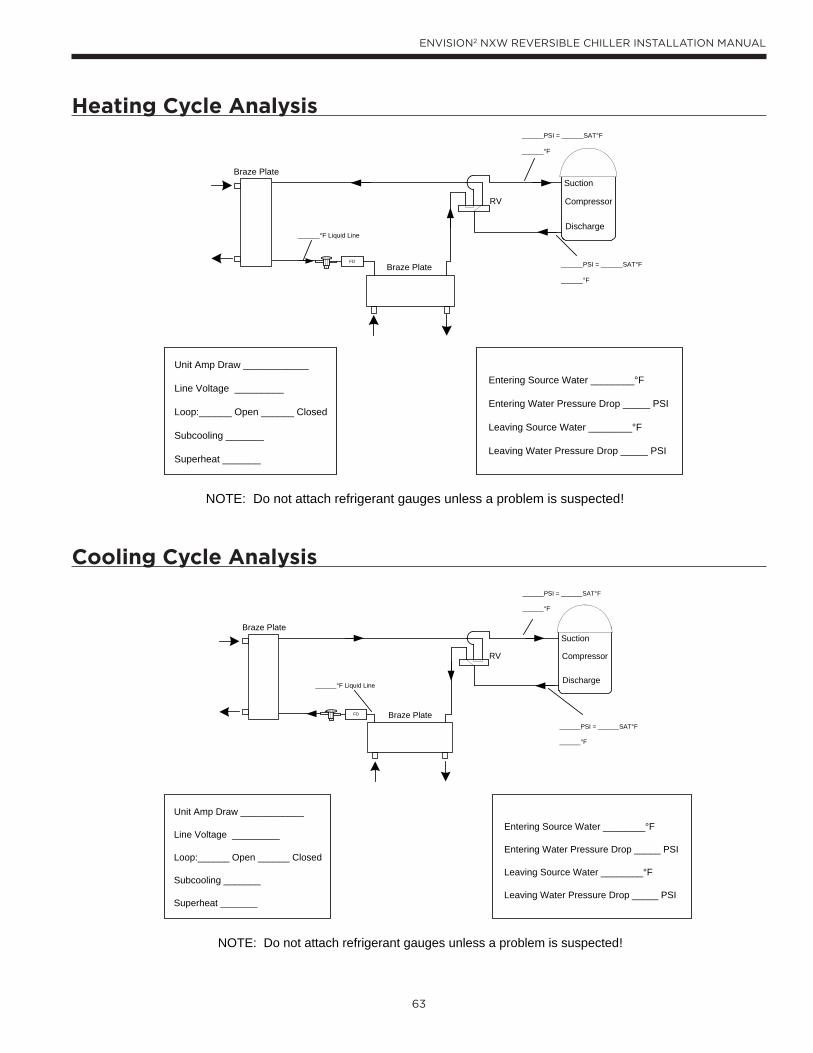
63
ENVISION2 NXW REVERSIBLE CHILLER INSTALLATION MANUAL
Heating Cycle Analysis
Cooling Cycle Analysis
Suction
Discharge
CompressorRV
Braze Plate
Braze PlateFD
Unit Amp Draw ____________
Line Voltage _________
Loop:______ Open ______ Closed
Subcooling _______
Superheat _______
Entering Source Water ________°F
Entering Water Pressure Drop _____ PSI
Leaving Source Water ________°F
Leaving Water Pressure Drop _____ PSI
______PSI = ______SAT°F
______°F
______PSI = ______SAT°F
______°F
______°F Liquid Line
NOTE: Do not attach refrigerant gauges unless a problem is suspected!
Suction
Discharge
CompressorRV
Braze Plate
Braze PlateFD
______PSI = ______SAT°F
______°F
______PSI = ______SAT°F
______°F
______°F Liquid Line
Unit Amp Draw ____________
Line Voltage _________
Loop:______ Open ______ Closed
Subcooling _______
Superheat _______
Entering Source Water ________°F
Entering Water Pressure Drop _____ PSI
Leaving Source Water ________°F
Leaving Water Pressure Drop _____ PSI
NOTE: Do not attach refrigerant gauges unless a problem is suspected!
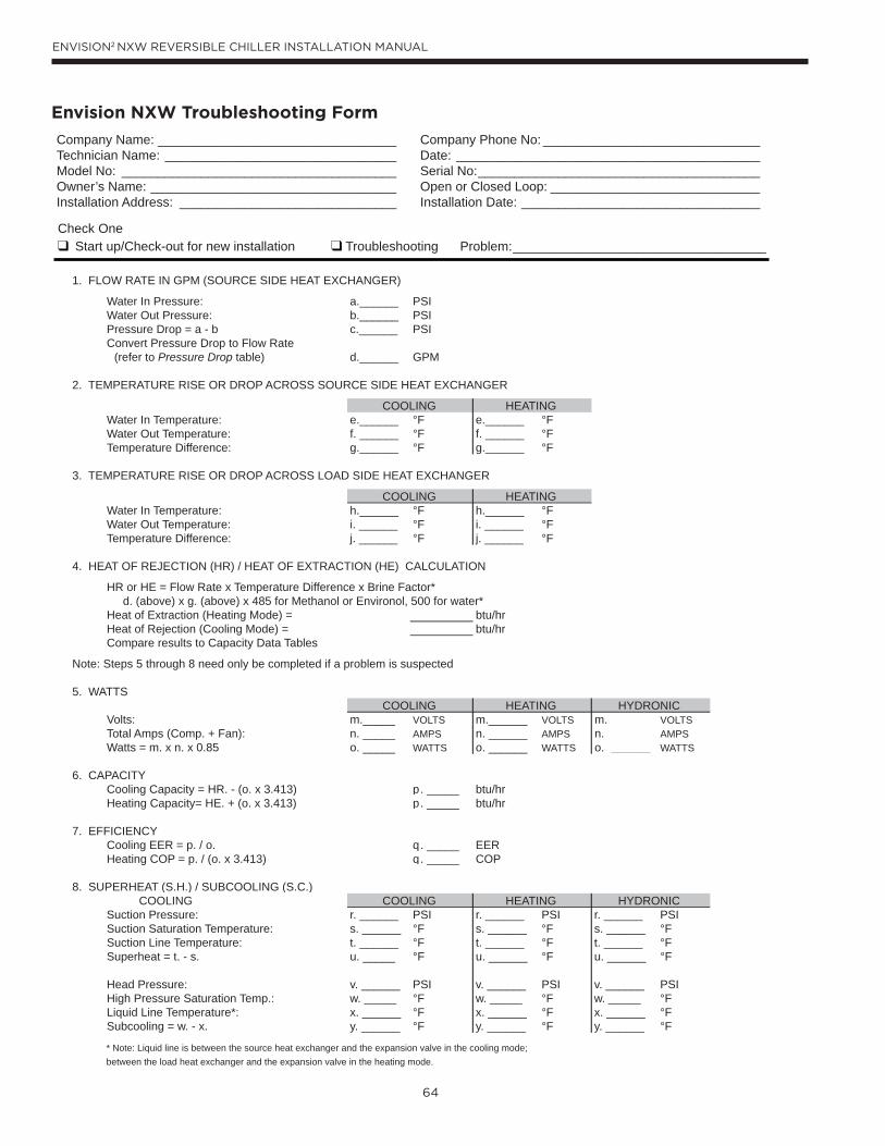
64
ENVISION2 NXW REVERSIBLE CHILLER INSTALLATION MANUAL
Check One Start up/Check-out for new installation Troubleshooting Problem:___________________________________
1. FLOW RATE IN GPM (SOURCE SIDE HEAT EXCHANGER)
Water In Pressure: a.______ PSIWater Out Pressure: b.______ PSIPressure Drop = a - b c.______ PSIConvert Pressure Drop to Flow Rate (refer to Pressure Drop table) d.______ GPM
2. TEMPERATURE RISE OR DROP ACROSS SOURCE SIDE HEAT EXCHANGER
COOLING HEATINGWater In Temperature: e.______ °F e.______ °FWater Out Temperature: f. ______ °F f. ______ °FTemperature Difference: g.______ °F g.______ °F
3. TEMPERATURE RISE OR DROP ACROSS LOAD SIDE HEAT EXCHANGER
COOLING HEATINGWater In Temperature: h.______ °F h.______ °FWater Out Temperature: i. ______ °F i. ______ °FTemperature Difference: j. ______ °F j. ______ °F
4. HEAT OF REJECTION (HR) / HEAT OF EXTRACTION (HE) CALCULATION
HR or HE = Flow Rate x Temperature Difference x Brine Factor* d. (above) x g. (above) x 485 for Methanol or Environol, 500 for water*Heat of Extraction (Heating Mode) = btu/hrHeat of Rejection (Cooling Mode) = btu/hrCompare results to Capacity Data Tables
Note: Steps 5 through 8 need only be completed if a problem is suspected
5. WATTSCOOLING HEATING HYDRONIC
Volts: m._____ VOLTS m.______ VOLTS m. ______ VOLTSTotal Amps (Comp. + Fan): n. _____ AMPS n. ______ AMPS n. ______ AMPSWatts = m. x n. x 0.85 o. _____ WATTS o. ______ WATTS o. ______ WATTS
6. CAPACITYCooling Capacity = HR. - (o. x 3.413) p. _____ btu/hrHeating Capacity= HE. + (o. x 3.413) p. _____ btu/hr
7. EFFICIENCYCooling EER = p. / o. q. _____ EERHeating COP = p. / (o. x 3.413) q. _____ COP
8. SUPERHEAT (S.H.) / SUBCOOLING (S.C.) COOLING HEATING HYDRONICSuction Pressure: r. ______ PSI r. ______ PSI r. ______ PSISuction Saturation Temperature: s. ______ °F s. ______ °F s. ______ °FSuction Line Temperature: t. ______ °F t. ______ °F t. ______ °FSuperheat = t. - s. u. _____ °F u. ______ °F u. ______ °F
Head Pressure: v. ______ PSI v. ______ PSI v. ______ PSIHigh Pressure Saturation Temp.: w. _____ °F w. _____ °F w. _____ °FLiquid Line Temperature*: x. ______ °F x. ______ °F x. ______ °FSubcooling = w. - x. y. ______ °F y. ______ °F y. ______ °F
* Note: Liquid line is between the source heat exchanger and the expansion valve in the cooling mode; between the load heat exchanger and the expansion valve in the heating mode.
Company Name: _________________________________Technician Name: ________________________________Model No: ______________________________________Owner’s Name: __________________________________Installation Address: ______________________________
Company Phone No: ______________________________Date: __________________________________________Serial No:_______________________________________Open or Closed Loop: _____________________________Installation Date: _________________________________
COOLING
Envision NXW Troubleshooting Form
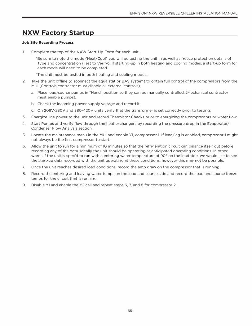
65
ENVISION2 NXW REVERSIBLE CHILLER INSTALLATION MANUAL
NXW Factory StartupJob Site Recording Process 1. Complete the top of the NXW Start-Up Form for each unit.
*Be sure to note the mode (Heat/Cool) you will be testing the unit in as well as freeze protection details of type and concentration (Test to Verify). If starting-up in both heating and cooling modes, a start-up form for each mode will need to be completed.
*The unit must be tested in both heating and cooling modes.
2. Take the unit offline (disconnect the aqua stat or BAS system) to obtain full control of the compressors from the MUI (Controls contractor must disable all external controls).
a. Place load/source pumps in “Hand” position so they can be manually controlled. (Mechanical contractor must enable pumps).
b. Check the incoming power supply voltage and record it.
c. On 208V-230V and 380-420V units verify that the transformer is set correctly prior to testing.
3. Energize line power to the unit and record Thermistor Checks prior to energizing the compressors or water flow.
4. Start Pumps and verify flow through the heat exchangers by recording the pressure drop in the Evaporator/Condenser Flow Analysis section.
5. Locate the maintenance menu in the MUI and enable Y1, compressor 1. If lead/lag is enabled, compressor 1 might not always be the first compressor to start.
6. Allow the unit to run for a minimum of 10 minutes so that the refrigeration circuit can balance itself out before recording any of the data. Ideally the unit should be operating at anticipated operating conditions. In other words if the unit is spec’d to run with a entering water temperature of 90° on the load side, we would like to see the start-up data recorded with the unit operating at these conditions, however this may not be possible.
7. Once the unit reaches desired load conditions, record the amp draw on the compressor that is running.
8. Record the entering and leaving water temps on the load and source side and record the load and source freeze temps for the circuit that is running.
9. Disable Y1 and enable the Y2 call and repeat steps 6, 7, and 8 for compressor 2.
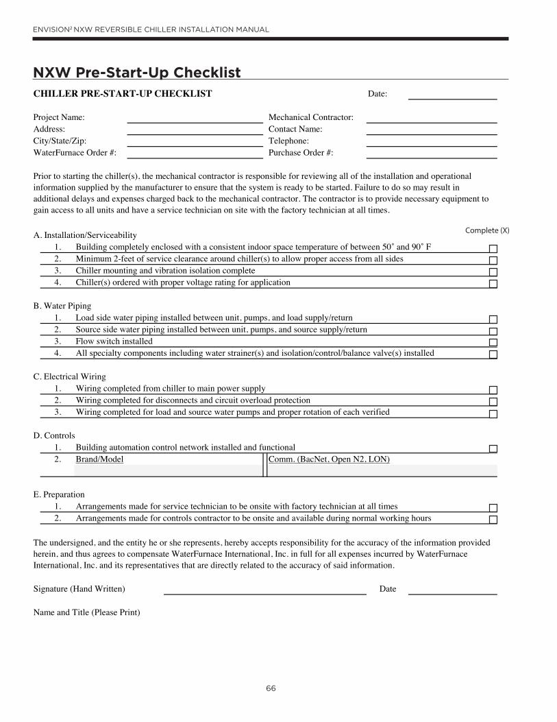
66
ENVISION2 NXW REVERSIBLE CHILLER INSTALLATION MANUAL
NXW Pre-Start-Up ChecklistCHILLER PRE-START-UP CHECKLIST Date:
Project Name: Mechanical Contractor: Address: Contact Name: City/State/Zip: Telephone: WaterFurnace Order #: Purchase Order #:
A. Installation/Serviceability 1. Building completely enclosed with a consistent indoor space temperature of between 50 and 90 F2. Minimum 2-feet of service clearance around chiller(s) to allow proper access from all sides 3. Chiller mounting and vibration isolation complete 4. Chiller(s) ordered with proper voltage rating for application
B. Water Piping1. Load side water piping installed between unit, pumps, and load supply/return2. Source side water piping installed between unit, pumps, and source supply/return3. Flow switch installed4. All specialty components including water strainer(s) and isolation/control/balance valve(s) installed
C. Electrical Wiring1. Wiring completed from chiller to main power supply2. Wiring completed for disconnects and circuit overload protection3. Wiring completed for load and source water pumps and proper rotation of each verified
D. Controls1. Building automation control network installed and functional2.
E. Preparation1. Arrangements made for service technician to be onsite with factory technician at all times2. Arrangements made for controls contractor to be onsite and available during normal working hours
Signature (Hand Written) Date
Name and Title (Please Print)
Prior to starting the chiller(s), the mechanical contractor is responsible for reviewing all of the installation and operational information supplied by the manufacturer to ensure that the system is ready to be started. Failure to do so may result in additional delays and expenses charged back to the mechanical contractor. The contractor is to provide necessary equipment to gain access to all units and have a service technician on site with the factory technician at all times.
Brand/Model Comm. (BacNet, Open N2, LON)
The undersigned, and the entity he or she represents, hereby accepts responsibility for the accuracy of the information provided herein, and thus agrees to compensate WaterFurnace International, Inc. in full for all expenses incurred by WaterFurnace International, Inc. and its representatives that are directly related to the accuracy of said information.
Complete (X)
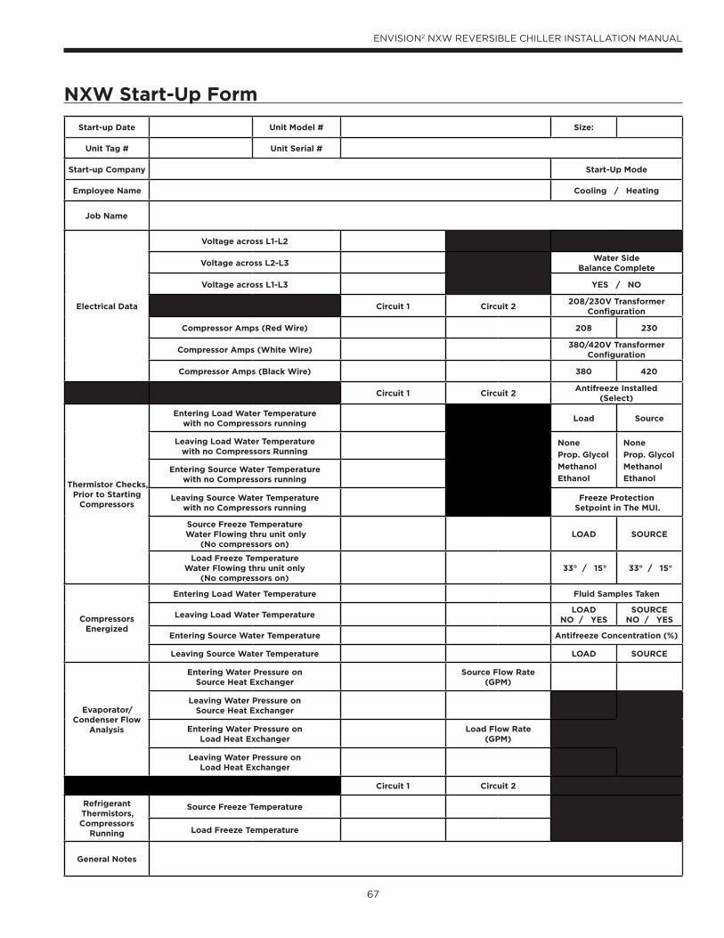
67
ENVISION2 NXW REVERSIBLE CHILLER INSTALLATION MANUAL
Start-up Date Unit Model # Size:
Unit Tag # Unit Serial #
Start-up Company Start-Up Mode
Employee Name Cooling / Heating
Job Name
Electrical Data
Voltage across L1-L2
Voltage across L2-L3Water Side
Balance Complete
Voltage across L1-L3 YES / NO
Circuit 1 Circuit 2208/230V Transformer
Configuration
Compressor Amps (Red Wire) 208 230
Compressor Amps (White Wire)380/420V Transformer
Configuration
Compressor Amps (Black Wire) 380 420
Circuit 1 Circuit 2Antifreeze Installed
(Select)
Thermistor Checks, Prior to Starting
Compressors
Entering Load Water Temperature with no Compressors running
Load Source
Leaving Load Water Temperaturewith no Compressors Running
None
Prop. Glycol
Methanol
Ethanol
None
Prop. Glycol
Methanol
EthanolEntering Source Water Temperature
with no Compressors running
Leaving Source Water Temperaturewith no Compressors running
Freeze ProtectionSetpoint in The MUI.
Source Freeze Temperature Water Flowing thru unit only
(No compressors on)LOAD SOURCE
Load Freeze Temperature Water Flowing thru unit only
(No compressors on)33° / 15° 33° / 15°
Compressors Energized
Entering Load Water Temperature Fluid Samples Taken
Leaving Load Water TemperatureLOAD
NO / YESSOURCE
NO / YES
Entering Source Water Temperature Antifreeze Concentration (%)
Leaving Source Water Temperature LOAD SOURCE
Evaporator/ Condenser Flow
Analysis
Entering Water Pressure onSource Heat Exchanger
Source Flow Rate(GPM)
Leaving Water Pressure onSource Heat Exchanger
Entering Water Pressure onLoad Heat Exchanger
Load Flow Rate(GPM)
Leaving Water Pressure onLoad Heat Exchanger
Circuit 1 Circuit 2
Refrigerant Thermistors, Compressors
Running
Source Freeze Temperature
Load Freeze Temperature
General Notes
NXW Start-Up Form
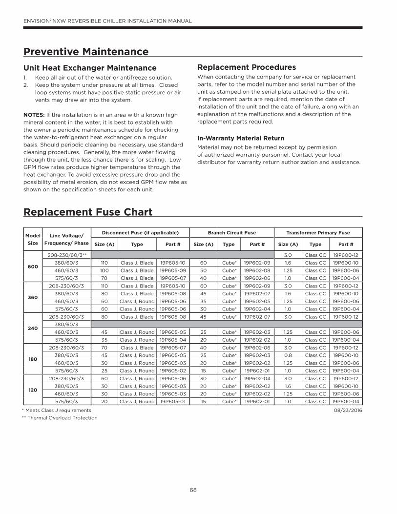
68
ENVISION2 NXW REVERSIBLE CHILLER INSTALLATION MANUAL
Unit Heat Exchanger Maintenance1. Keep all air out of the water or antifreeze solution.
2. Keep the system under pressure at all times. Closed
loop systems must have positive static pressure or air
vents may draw air into the system.
NOTES: If the installation is in an area with a known high
mineral content in the water, it is best to establish with
the owner a periodic maintenance schedule for checking
the water-to-refrigerant heat exchanger on a regular
basis. Should periodic cleaning be necessary, use standard
cleaning procedures. Generally, the more water flowing
through the unit, the less chance there is for scaling. Low
GPM flow rates produce higher temperatures through the
heat exchanger. To avoid excessive pressure drop and the
possibility of metal erosion, do not exceed GPM flow rate as
shown on the specification sheets for each unit.
Preventive Maintenance
Replacement ProceduresWhen contacting the company for service or replacement
parts, refer to the model number and serial number of the
unit as stamped on the serial plate attached to the unit.
If replacement parts are required, mention the date of
installation of the unit and the date of failure, along with an
explanation of the malfunctions and a description of the
replacement parts required.
In-Warranty Material Return
Material may not be returned except by permission
of authorized warranty personnel. Contact your local
distributor for warranty return authorization and assistance.
Replacement Fuse Chart
Model
Size
Line Voltage/
Frequency/ Phase
Disconnect Fuse (if applicable) Branch Circuit Fuse Transformer Primary Fuse
Size (A) Type Part # Size (A) Type Part # Size (A) Type Part #
600
208-230/60/3** 3.0 Class CC 19P600-12
380/60/3 110 Class J, Blade 19P605-10 60 Cube* 19P602-09 1.6 Class CC 19P600-10
460/60/3 100 Class J, Blade 19P605-09 50 Cube* 19P602-08 1.25 Class CC 19P600-06
575/60/3 70 Class J, Blade 19P605-07 40 Cube* 19P602-06 1.0 Class CC 19P600-04
360
208-230/60/3 110 Class J, Blade 19P605-10 60 Cube* 19P602-09 3.0 Class CC 19P600-12
380/60/3 80 Class J, Blade 19P605-08 45 Cube* 19P602-07 1.6 Class CC 19P600-10
460/60/3 60 Class J, Round 19P605-06 35 Cube* 19P602-05 1.25 Class CC 19P600-06
575/60/3 60 Class J, Round 19P605-06 30 Cube* 19P602-04 1.0 Class CC 19P600-04
240
208-230/60/3 80 Class J, Blade 19P605-08 45 Cube* 19P602-07 3.0 Class CC 19P600-12
380/60/3
460/60/3 45 Class J, Round 19P605-05 25 Cube* 19P602-03 1.25 Class CC 19P600-06
575/60/3 35 Class J, Round 19P605-04 20 Cube* 19P602-02 1.0 Class CC 19P600-04
180
208-230/60/3 70 Class J, Blade 19P605-07 40 Cube* 19P602-06 3.0 Class CC 19P600-12
380/60/3 45 Class J, Round 19P605-05 25 Cube* 19P602-03 0.8 Class CC 19P600-10
460/60/3 30 Class J, Round 19P605-03 20 Cube* 19P602-02 1.25 Class CC 19P600-06
575/60/3 25 Class J, Round 19P605-02 15 Cube* 19P602-01 1.0 Class CC 19P600-04
120
208-230/60/3 60 Class J, Round 19P605-06 30 Cube* 19P602-04 3.0 Class CC 19P600-12
380/60/3 30 Class J, Round 19P605-03 20 Cube* 19P602-02 1.6 Class CC 19P600-10
460/60/3 30 Class J, Round 19P605-03 20 Cube* 19P602-02 1.25 Class CC 19P600-06
575/60/3 20 Class J, Round 19P605-01 15 Cube* 19P602-01 1.0 Class CC 19P600-04
* Meets Class J requirements 08/23/2016
** Thermal Overload Protection
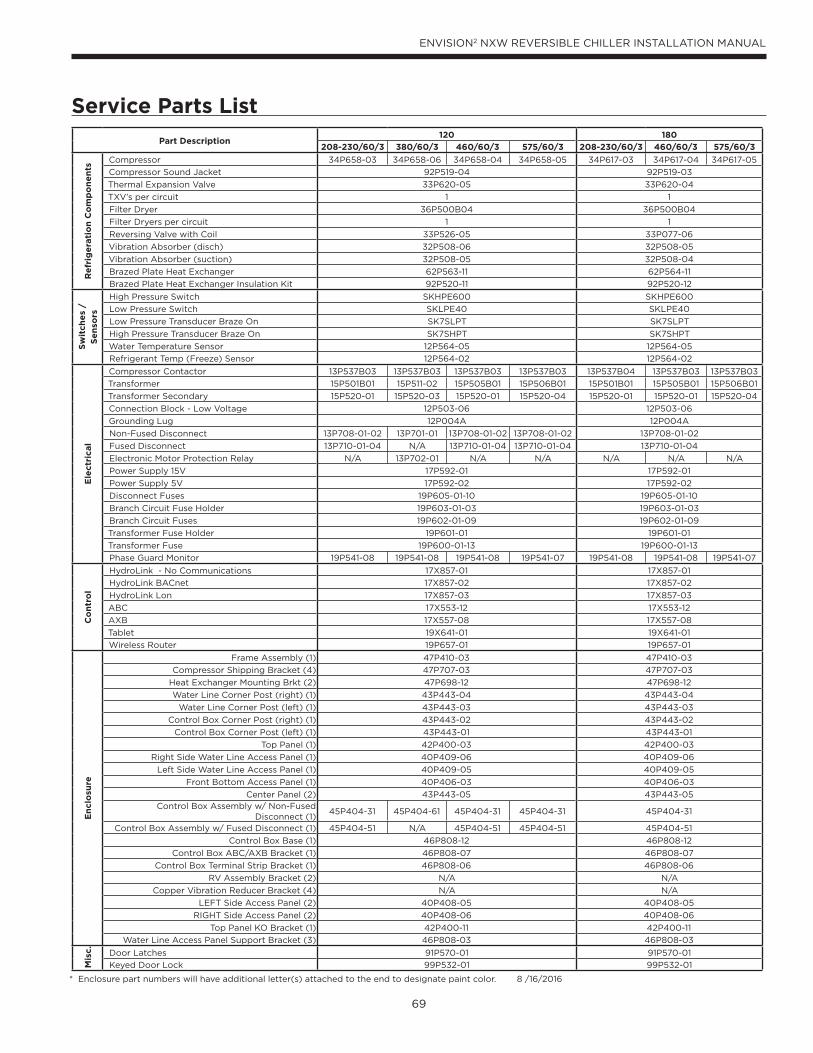
69
ENVISION2 NXW REVERSIBLE CHILLER INSTALLATION MANUAL
Service Parts List
Part Description120 180
208-230/60/3 380/60/3 460/60/3 575/60/3 208-230/60/3 460/60/3 575/60/3
Re
frig
era
tio
n C
om
po
ne
nts
Compressor 34P658-03 34P658-06 34P658-04 34P658-05 34P617-03 34P617-04 34P617-05
Compressor Sound Jacket 92P519-04 92P519-03
Thermal Expansion Valve 33P620-05 33P620-04
TXV’s per circuit 1 1
Filter Dryer 36P500B04 36P500B04
Filter Dryers per circuit 1 1
Reversing Valve with Coil 33P526-05 33P077-06
Vibration Absorber (disch) 32P508-06 32P508-05
Vibration Absorber (suction) 32P508-05 32P508-04
Brazed Plate Heat Exchanger 62P563-11 62P564-11
Brazed Plate Heat Exchanger Insulation Kit 92P520-11 92P520-12
Sw
itch
es
/
Se
nso
rs
High Pressure Switch SKHPE600 SKHPE600
Low Pressure Switch SKLPE40 SKLPE40
Low Pressure Transducer Braze On SK7SLPT SK7SLPT
High Pressure Transducer Braze On SK7SHPT SK7SHPT
Water Temperature Sensor 12P564-05 12P564-05
Refrigerant Temp (Freeze) Sensor 12P564-02 12P564-02
Ele
ctr
ical
Compressor Contactor 13P537B03 13P537B03 13P537B03 13P537B03 13P537B04 13P537B03 13P537B03
Transformer 15P501B01 15P511-02 15P505B01 15P506B01 15P501B01 15P505B01 15P506B01
Transformer Secondary 15P520-01 15P520-03 15P520-01 15P520-04 15P520-01 15P520-01 15P520-04
Connection Block - Low Voltage 12P503-06 12P503-06
Grounding Lug 12P004A 12P004A
Non-Fused Disconnect 13P708-01-02 13P701-01 13P708-01-02 13P708-01-02 13P708-01-02
Fused Disconnect 13P710-01-04 N/A 13P710-01-04 13P710-01-04 13P710-01-04
Electronic Motor Protection Relay N/A 13P702-01 N/A N/A N/A N/A N/A
Power Supply 15V 17P592-01 17P592-01
Power Supply 5V 17P592-02 17P592-02
Disconnect Fuses 19P605-01-10 19P605-01-10
Branch Circuit Fuse Holder 19P603-01-03 19P603-01-03
Branch Circuit Fuses 19P602-01-09 19P602-01-09
Transformer Fuse Holder 19P601-01 19P601-01
Transformer Fuse 19P600-01-13 19P600-01-13
Phase Guard Monitor 19P541-08 19P541-08 19P541-08 19P541-07 19P541-08 19P541-08 19P541-07
Co
ntr
ol
HydroLink - No Communications 17X857-01 17X857-01
HydroLink BACnet 17X857-02 17X857-02
HydroLink Lon 17X857-03 17X857-03
ABC 17X553-12 17X553-12
AXB 17X557-08 17X557-08
Tablet 19X641-01 19X641-01
Wireless Router 19P657-01 19P657-01
En
clo
sure
Frame Assembly (1) 47P410-03 47P410-03
Compressor Shipping Bracket (4) 47P707-03 47P707-03
Heat Exchanger Mounting Brkt (2) 47P698-12 47P698-12
Water Line Corner Post (right) (1) 43P443-04 43P443-04
Water Line Corner Post (left) (1) 43P443-03 43P443-03
Control Box Corner Post (right) (1) 43P443-02 43P443-02
Control Box Corner Post (left) (1) 43P443-01 43P443-01
Top Panel (1) 42P400-03 42P400-03
Right Side Water Line Access Panel (1) 40P409-06 40P409-06
Left Side Water Line Access Panel (1) 40P409-05 40P409-05
Front Bottom Access Panel (1) 40P406-03 40P406-03
Center Panel (2) 43P443-05 43P443-05Control Box Assembly w/ Non-Fused
Disconnect (1)45P404-31 45P404-61 45P404-31 45P404-31 45P404-31
Control Box Assembly w/ Fused Disconnect (1) 45P404-51 N/A 45P404-51 45P404-51 45P404-51
Control Box Base (1) 46P808-12 46P808-12
Control Box ABC/AXB Bracket (1) 46P808-07 46P808-07
Control Box Terminal Strip Bracket (1) 46P808-06 46P808-06
RV Assembly Bracket (2) N/A N/A
Copper Vibration Reducer Bracket (4) N/A N/A
LEFT Side Access Panel (2) 40P408-05 40P408-05
RIGHT Side Access Panel (2) 40P408-06 40P408-06
Top Panel KO Bracket (1) 42P400-11 42P400-11
Water Line Access Panel Support Bracket (3) 46P808-03 46P808-03
Mis
c.
Door Latches 91P570-01 91P570-01
Keyed Door Lock 99P532-01 99P532-01
* Enclosure part numbers will have additional letter(s) attached to the end to designate paint color. 8 /16/2016

70
ENVISION2 NXW REVERSIBLE CHILLER INSTALLATION MANUAL
Service Parts List, cont.
Part Description240 360
208-230/60/3 460/60/3 575/60/3 208-230/60/3 380/60/3 460/60/3 575/60/3
Re
frig
era
tio
n C
om
po
ne
nts
Compressor 34P619-03 34P619-04 34P619-05 34P655-03 34P655-06 34P655-04 34P655-05
Compressor Sound Jacket 92P519-03 92P519-05
Thermal Expansion Valve 33P620-03 33P620-02
TXV’s per circuit 1 1
Filter Dryer 36P500B04 36P500B06
Filter Dryers per circuit 1 1
Reversing Valve with Coil 33P546-04 33P546-04
Vibration Absorber (disch) 32P508-04 32P508-04
Vibration Absorber (suction) 32P508-03 32P508-03
Brazed Plate Heat Exchanger 62P550-11 62P551-11
Brazed Plate Heat Exchanger Insulation Kit 92P520-13 92P516-11
Sw
itch
es
/
Se
nso
rs
High Pressure Switch SKHPE600 SKHPE600
Low Pressure Switch SKLPE40 SKLPE40
Low Pressure Transducer Braze On SK7SLPT SK7SLPT
High Pressure Transducer Braze On SK7SHPT SK7SHPT
Water Temperature Sensor 12P564-05 12P564-05
Refrigerant Temp (Freeze) Sensor 12P564-02 12P564-02
Ele
ctr
ical
Compressor Contactor 13P537B05 13P537B03 13P537B03 13P537B05 13P537B05 13P537B04 13P537B04
Transformer 15P501B01 15P505B01 15P506B01 15P501B01 15P511-02 15P505B01 15P506B01
Transformer Secondary 15P520-01 15P520-01 15P520-04 15P520-01 15P520-03 15P520-01 15P520-04
Connection Block - Low Voltage 12P503-06 12P503-06
Grounding Lug 12P004A 12P004A
Non-Fused Disconnect 13P708-01-02 13P708-01-02 13P701-01 13P708-01-02 13P708-01-02
Fused Disconnect 13P710-01-04 13P710-01-04 N/A 13P710-01-04 13P710-01-04
Electronic Motor Protection Relay N/A N/A N/A N/A 13P702-01 N/A N/A
Power Supply 15V 17P592-01 17P592-01
Power Supply 5V 17P592-02 17P592-02
Disconnect Fuses 19P605-01-10 19P605-01-10
Branch Circuit Fuse Holder 19P603-01-03 19P603-01-03
Branch Circuit Fuses 19P602-01-09 19P602-01-09
Transformer Fuse Holder 19P601-01 19P601-01
Transformer Fuse 19P600-01-13 19P600-01-13
Phase Guard Monitor 19P541-08 19P541-08 19P541-07 19P541-08 19P541-08 19P541-08 19P541-07
Co
ntr
ol
HydroLink - No Communications 17X857-01 17X857-01
HydroLink BACnet 17X857-02 17X857-02
HydroLink Lon 17X857-03 17X857-03
ABC 17X553-12 17X553-12
AXB 17X557-08 17X557-08
Tablet 19X641-01 19X641-01
Wireless Router 19P657-01 19P657-01
En
clo
sure
Frame Assembly (1) 47P410-02 47P410-02
Compressor Shipping Bracket (4) 47P707-03 47P707-04
Heat Exchanger Mounting Brkt (2) 47P698-11 47P698-11
Water Line Corner Post (right) (1) 43P442-04 43P442-04
Water Line Corner Post (left) (1) 43P442-03 43P442-03
Control Box Corner Post (right) (1) 43P442-02 43P442-02
Control Box Corner Post (left) (1) 43P442-01 43P442-01
Top Panel (1) 42P400-02 42P400-02
Right Side Water Line Access Panel (1) 40P409-04 40P409-04
Left Side Water Line Access Panel (1) 40P409-03 40P409-03
Front Bottom Access Panel (1) 40P406-02 40P406-02
Center Panel (2) 43P442-05 43P442-05Control Box Assembly w/ Non-Fused
Disconnect (1)45P404-31 45P404-31 45P404-61 45P404-31 45P404-31
Control Box Assembly w/ Fused Disconnect (1) 45P404-51 45P404-51 N/A 45P404-51 45P404-51
Control Box Base (1) 46P808-12 46P808-12
Control Box ABC/AXB Bracket (1) 46P808-07 46P808-07
Control Box Terminal Strip Bracket (1) 46P808-06 46P808-06
RV Assembly Bracket (2) N/A N/A
Copper Vibration Reducer Bracket (4) N/A N/A
LEFT Side Access Panel (2) 40P408-03 40P408-03
RIGHT Side Access Panel (2) 40P408-04 40P408-04
Top Panel KO Bracket (1) 42P400-11 42P400-11
Water Line Access Panel Support Bracket (3) 46P808-03 46P808-03
Mis
c.
Door Latches 91P570-01 91P570-01
Keyed Door Lock 99P532-01 99P532-01
* Enclosure part numbers will have additional letter(s) attached to the end to designate paint color. 8 /16/2016
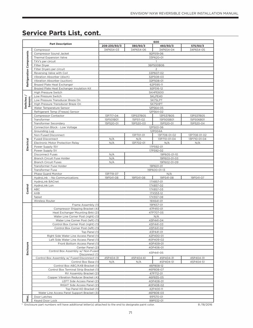
71
ENVISION2 NXW REVERSIBLE CHILLER INSTALLATION MANUAL
Service Parts List, cont.
Part Description600
208-230/60/3 380/60/3 460/60/3 575/60/3
Re
frig
era
tio
n C
om
po
ne
nts
Compressor 34P654-03 34P654-06 34P654-04 34P654-05
Compressor Sound Jacket 92P519-06
Thermal Expansion Valve 33P620-01
TXV’s per circuit 1
Filter Dryer 36P500B06
Filter Dryers per circuit 2
Reversing Valve with Coil 33P607-02
Vibration Absorber (disch) 32P508-03
Vibration Absorber (suction) 32P508-01
Brazed Plate Heat Exchanger 62P595-11
Brazed Plate Heat Exchanger Insulation Kit 92P516-12
Sw
itch
es
/
Se
nso
rs
High Pressure Switch SKHPE600
Low Pressure Switch SKLPE40
Low Pressure Transducer Braze On SK7SLPT
High Pressure Transducer Braze On SK7SHPT
Water Temperature Sensor 12P564-05
Refrigerant Temp (Freeze) Sensor 12P564-02
Ele
ctr
ical
Compressor Contactor 13P717-04 13P537B05 13P537B05 13P537B05
Transformer 15P501B01 15P511-02 15P505B01 15P506B01
Transformer Secondary 15P520-01 15P520-03 15P520-01 15P520-04
Connection Block - Low Voltage 12P503-06
Grounding Lug 12P004A
Non-Fused Disconnect 13P701-01 13P708-01-02 13P708-01-02
Fused Disconnect N/A N/A 13P710-01-04 13P710-01-04
Electronic Motor Protection Relay N/A 13P702-01 N/A N/A
Power Supply 15V 17P592-01
Power Supply 5V 17P592-02
Disconnect Fuses N/A 19P605-01-10
Branch Circuit Fuse Holder N/A 19P603-01-03
Branch Circuit Fuses N/A 19P602-01-09
Transformer Fuse Holder 19P601-01
Transformer Fuse 19P600-01-13
Phase Guard Monitor 13P719-07 N/A
Co
ntr
ol
HydroLink - No Communications 19P541-08 19P541-08 19P541-08 19P541-07
HydroLink BACnet 17X857-01
HydroLink Lon 17X857-02
ABC 17X857-03
AXB 17X553-12
Tablet 17X557-08
Wireless Router 19X641-01
En
clo
sure
Frame Assembly (1) 19P657-01
Compressor Shipping Bracket (4) 47P410-01
Heat Exchanger Mounting Brkt (2) 47P707-05
Water Line Corner Post (right) (1) N/A
Water Line Corner Post (left) (1) 43P441-04
Control Box Corner Post (right) (1) 43P441-03
Control Box Corner Post (left) (1) 43P441-02
Top Panel (1) 43P441-01
Right Side Water Line Access Panel (1) 42P400-01
Left Side Water Line Access Panel (1) 40P409-02
Front Bottom Access Panel (1) 40P409-01
Center Panel (2) 40P406-01Control Box Assembly w/ Non-Fused
Disconnect (1)43P441-05
Control Box Assembly w/ Fused Disconnect (1) 45P404-31 45P404-61 45P404-31 45P404-31
Control Box Base (1) N/A N/A 45P404-51 45P404-51
Control Box ABC/AXB Bracket (1) 46P808-12
Control Box Terminal Strip Bracket (1) 46P808-07
RV Assembly Bracket (2) 47P712-01
Copper Vibration Reducer Bracket (4) 46P835-05
LEFT Side Access Panel (2) 40P408-01
RIGHT Side Access Panel (2) 40P408-02
Top Panel KO Bracket (1) 42P400-11
Water Line Access Panel Support Bracket (3) 46P808-03
Mis
c.
Door Latches 91P570-01
Keyed Door Lock 99P532-01
* Enclosure part numbers will have additional letter(s) attached to the end to designate paint color. 8 /18/2016

72
ENVISION2 NXW REVERSIBLE CHILLER INSTALLATION MANUAL
Pages: Description: Date: By:
All Updated with HydroLink Aurora Controls, Removed FX10 Option Aug 25 2016 MA
All First Published 02 Jun 2014 DS
Revision Guide


Manufactured by
WaterFurnace International, Inc.
9000 Conservation Way
Fort Wayne, IN 46809
www.waterfurnace.com
©2016 WaterFurnace International, Inc., 9000 Conservation Way, Fort Wayne, IN 46809-9794. WaterFurnace has a policy of continual product research and development and
reserves the right to change design and specifi cations without notice.
Product: Envision2 NXW
Type: Reversible Chiller - 60 Hz
Size: 10-50 Tons
Document: Installation ManualIM2502WNB 08/16