nxp 0500 - 1650 water-water multipurpose
TRANSCRIPT

NXP-0500-1650-HP-W_Y_UN50_06 www.aermec.com
DESCRIPTIONMulti-purpose indoor model designed for applications with 2 or 4-pipe systems. Just one unit is capable of satisfying the yearly hot and cold water demand simultaneously and independently.The base, the structure and the panels are made of galvanized steel treated with polyester paint RAL 9003.
VERSIONS° StandardL Standard silenced
FEATURES Operating fieldWork at full load with chilled water production from 4 to 18°C at the evaporator and hot water at the condenser up to 55 °C.(for more information, refer to the technical documentation).
Dual-circuit unitThe units are dual-circuit, to ensure maximum efficiency both at full load and at partial load.
ExchangersAll standard units have user-side heat exchangers and plate recovery, optimised to take advantage of the excellent heat exchange character-istics of the R410A.
Option integrated hydronic kitTo obtain a solution that offers economic savings and easy installation, these units can be configured with an integrated hydronic kit on both the service side and the recovery side.The kit contains the main hydraulic components, and is available in var-ious configurations with a single pump or a standby pump too, so the customer can choose the right useful head.
■ The flow switch is available as an accessory for both the system side and the recovery side, and is compulsory; if it is not installed, the warranty will be considered invalid.
CONTROL PCO⁵Microprocessor adjustment, with keyboard and LCD display,for easy ac-cess on the unit is a menu available in several languages.— Possibility to control two units in a Master-Slave configuration— The presence of a programmable timer allows functioning time pe-
riods and a possible second set-point to be set.— The temperature control takes place with the integral proportional
logic, based on the water output temperature.
ACCESSORIESAER485P1: RS-485 interface for supervision systems with MODBUS protocol.AERBACP: Ethernet communication Interface for protocols Bacnet/IP, Modbus TCP/IP, SNMPAERNET: The device allows the control, the management and the re-mote monitoring of a Chiller with a PC, smartphone or tablet using Cloud connection. AERNET works as Master while every unit connected is configured as Slave (max. 6 unit); also, with a simple click is possible to save a log file with all the connected unit datas in the personal ter-minal for post analysis.FL: Flow switch.MULTICHILLER_EVO: Control, switch-on and switch-off system of the single chillers where multiple units are installed in parallel, always en-suring constant flow rate to the evaporators.PGD1: Allows you to control the unit at a distance.AVX: Spring anti-vibration supports.
FACTORY FITTED ACCESSORIESDRE: Electronic device for peak current reduction.RIF: Power factor correction. Connected in parallel to the motor allow-ing about 10% reduction of input current.
NXP 0500 - 1650
• Units designed for 2 or 4-pipe systems• High efficiency also at partial loads• Simultaneous and independent
production of hot and chilled water
50Hz
Water-water multipurposeCooling capacity 108 ÷ 502 kWHeating capacity 122 ÷ 549 kW

www.aermec.com NXP-0500-1650-HP-W_Y_UN50_06
ACCESSORIES COMPATIBILITYModel Ver 0500 0550 0600 0650 0700 0750 0800 0900 1000 1250 1400 1500 1650AER485P1 °,L • • • • • • • • • • • • •AERBACP °,L • • • • • • • • • • • • •AERNET °,L • • • • • • • • • • • • •FL °,L • • • • • • • • • • • • •MULTICHILLER_EVO °,L • • • • • • • • • • • • •PGD1 °,L • • • • • • • • • • • • •
Antivibration
Version
Integrated hydronic kit, user
side
Integrated hydronic
kit, recovery side
0500 0550 0600 0650 0700 0750 0800 0900 1000 1250 1400 1500 1650
° ° ° AVX350 AVX350 AVX351 AVX351 AVX351 AVX351 AVX352 AVX352 AVX353 AVX353 AVX353 AVX354 AVX354° ° U,V AVX357 AVX357 AVX358 AVX358 AVX358 AVX359 AVX360 AVX360 AVX361 AVX361 AVX361 AVX361 AVX361° M,N °,U,V,W,Z AVX357 AVX357 AVX358 AVX358 AVX358 AVX359 AVX360 AVX360 AVX361 AVX361 AVX361 AVX361 AVX361° O,P U,V AVX357 AVX357 AVX358 AVX358 AVX358 AVX359 AVX360 AVX360 AVX361 AVX361 AVX361 AVX361 AVX361° ° W,Z AVX357 AVX357 AVX359 AVX359 AVX359 AVX359 AVX363 AVX363 AVX364 AVX364 AVX364 AVX364 AVX364° O,P °,W,Z AVX357 AVX357 AVX359 AVX359 AVX359 AVX359 AVX363 AVX363 AVX364 AVX364 AVX364 AVX364 AVX364L ° ° AVX351 AVX351 AVX359 AVX359 AVX359 AVX356 AVX353 AVX353 AVX353 AVX354 AVX354 AVX354 AVX354L ° U,V AVX358 AVX358 AVX359 AVX359 AVX359 AVX360 AVX360 AVX360 AVX361 AVX361 AVX362 AVX362 AVX362L M,N °,U,V AVX358 AVX358 AVX359 AVX359 AVX359 AVX360 AVX360 AVX360 AVX361 AVX361 AVX362 AVX362 AVX362L °,M,N W,Z AVX359 AVX359 AVX359 AVX359 AVX359 AVX363 AVX363 AVX364 AVX364 AVX364 AVX364 AVX364 AVX364L O,P °,U,V,W,Z AVX359 AVX359 AVX359 AVX359 AVX359 AVX363 AVX363 AVX364 AVX364 AVX364 AVX364 AVX364 AVX364
Device for peak current reductionVer 0500 0550 0600 0650 0700 0750 0800 0900 1000 1250 1400 1500 1650°,L DRE501 (1) DRE551 (1) DRE601 (1) DRE651 (1) DRE701 (1) DRE751 (1) DRE801 (1) DRE901 (1) DRE1001 (1) DRE1251 (1) DRE1401 (1) DRE1401 (1) DRE1401 (1)
(1) Only for supplies of 400V 3N ~ 50Hz and 400V 3 ~ 50Hz. x 2 or x 3 (if present) indicates the quantity to be ordered.A grey background indicates the accessory must be assembled in the factory
Power factor correctionVer 0500 0550 0600 0650 0700 0750 0800 0900 1000 1250 1400 1500 1650°,L RIF98 RIF98 RIF95 RIF95 RIF95 RIF95 RIF95 RIF96 RIF97 RIF97 RIF97 RIF97 RIF97
A grey background indicates the accessory must be assembled in the factory
CONFIGURATORField Description1,2,3 NXP
4,5,6,7 Size0500, 0550, 0600, 0650, 0700, 0750, 0800, 0900, 1000, 1250, 1400, 1500, 1650
8 Operating field° Standard mechanic thermostatic valve
9 System type2 2-pipe system 4 4-pipe system
10 Version° StandardL Standard silenced
11 Power supply° 400V ~ 3 50Hz with magnet circuit breakers4 220V ~ 3 50Hz with magnet circuit breakers (1)5 500V ~ 3 50Hz with magnet circuit breakers (2)
12 Integrated hydronic kit, user side° Without hydronic kitM Single pump low headN Pump low head + stand-by pumpO Single pump high headP Pump high head + stand-by pump
13 Integrated hydronic kit, recovery side° Without hydronic kitU Single pump low headV Pump low head + stand-by pumpW Single pump high headZ Pump high head + stand-by pump
(1) Only for sizes from 0500 to 0700(2) Only for sizes from 0800 to 1000

NXP-0500-1650-HP-W_Y_UN50_06 www.aermec.com
PERFORMANCE SPECIFICATIONS NXP - 2-pipe system versions °/LSize 0500 0550 0600 0650 0700 0750 0800 0900 1000 1250 1400 1500 1650Cooling system side 2-pipe system (1)Cooling capacity kW 108,9 117,0 141,5 157,5 192,7 218,5 252,2 281,0 305,8 345,2 392,3 447,2 502,4Input power kW 24,0 26,1 30,9 35,1 42,6 48,9 56,0 62,5 66,3 75,7 85,2 98,4 110,3Cooling input current A 47,0 50,0 58,0 65,0 84,0 90,0 92,0 101,0 106,0 135,0 149,0 169,0 188,0EER W/W 4,54 4,48 4,58 4,49 4,52 4,47 4,51 4,50 4,61 4,56 4,60 4,55 4,55Water flow rate source side l/h 22711 24436 29455 32877 40143 45586 52705 58706 63673 71963 81633 93177 104621Pressure drop source side kPa 33 37 41 50 59 69 28 34 26 32 36 45 49Water flow rate system side l/h 18734 20124 24349 27108 33155 37599 43386 48338 52596 59364 67464 76904 86389Pressure drop system side kPa 19 21 21 25 27 29 20 25 19 23 26 32 34Heating system side 2-pipe system (2)Heating capacity kW 122,4 131,0 158,2 175,7 210,0 238,7 289,0 320,9 352,6 383,7 433,5 489,5 549,4Input power kW 29,6 32,0 38,5 43,3 51,7 59,6 70,9 79,3 84,0 91,7 103,4 118,6 132,1Heating input current A 54,0 58,0 68,0 76,0 95,0 103,0 112,0 123,0 130,0 154,0 173,0 196,0 217,0COP W/W 4,13 4,09 4,11 4,05 4,06 4,00 4,08 4,05 4,20 4,18 4,19 4,13 4,16Water flow rate source side l/h 27209 29066 35169 38937 46642 52841 63935 70917 78660 85555 96778 108934 122632Pressure drop source side kPa 47 52 58 69 79 92 41 50 39 45 51 62 67Water flow rate system side l/h 21232 22726 27452 30476 36453 41427 50177 55720 61233 66632 75270 84987 95403Pressure drop system side kPa 25 27 27 32 32 36 27 33 25 29 32 39 42Heating domestic hot water side 2-pipe system (3)Heating capacity kW 124,5 133,2 161,0 178,8 213,6 242,8 293,3 325,1 354,8 390,1 439,8 496,5 558,6Input power kW 29,2 31,6 37,8 42,6 50,9 58,4 70,0 78,4 83,2 91,1 102,6 117,8 131,6Heating total input current A 54,0 57,0 67,0 75,0 95,0 103,0 110,0 122,0 129,0 153,0 171,0 194,0 216,0COP W/W 4,26 4,21 4,26 4,20 4,19 4,16 4,19 4,15 4,26 4,28 4,29 4,21 4,24Water flow rate source side l/h 27905 29767 36085 39952 47734 54174 65416 72379 79441 87568 98845 111238 125462Pressure drop source side kPa 37 42 41 50 53 58 42 50 38 46 52 66 70Water flow rate domestic hot water side l/h 21604 23109 27936 31015 37062 42149 50928 56446 61601 67743 76363 86215 96994Pressure drop domestic hot water side kPa 23 26 25 30 33 36 26 32 23 28 33 40 43Simultaneous operation (heating + cooling), 2 pipes (4)Cooling capacity kW 96,2 102,5 124,8 138,9 165,4 190,6 225,7 250,3 282,6 308,1 340,2 392,0 444,9Recovered heating power kW 123,3 131,9 160,0 178,4 212,6 244,6 290,8 322,7 360,1 392,6 435,1 500,6 566,0Input power kW 28,2 30,5 36,5 40,9 49,0 56,2 67,8 75,5 80,9 88,2 99,2 113,9 126,6Water flow rate system side l/h 18734 20124 24349 27108 33155 37599 43386 48338 52596 59364 67464 76904 86389Pressure drop system side kPa 19 21 21 25 27 29 20 25 19 23 26 32 34Water flow rate domestic hot water side l/h 21604 23109 27936 31015 37062 42149 50928 56446 61601 67743 76363 86215 96994Pressure drop domestic hot water side kPa 23 26 25 30 33 36 26 32 23 28 33 40 43
(1) Date 14511:2018; Water user side 12 °C / 7 °C; Water source side 30 °C / 35 °C; All the units are Eurovent certified(2) Date 14511:2018; Water user side 40 °C / 45 °C; Water source side 10 °C / 7 °C(3) Water exchanger to the total recovery side 40 °C / 45 °C; Water source side 10 °C / 7 °C(4) Water exchanger to the total recovery side * / 45 °C; Water to the system side heat exchanger * / 7 °C;

www.aermec.com NXP-0500-1650-HP-W_Y_UN50_06
NXP - 4-pipe system versions °/LSize 0500 0550 0600 0650 0700 0750 0800 0900 1000 1250 1400 1500 1650Cooling system side 4-pipe system (1)Cooling capacity kW 108,9 117,0 141,5 154,5 192,7 218,5 252,2 281,0 305,8 345,2 392,3 447,2 502,4Input power kW 24,0 26,1 30,9 35,1 42,6 48,9 56,0 62,5 66,3 75,7 85,2 98,4 110,3Cooling input current A 47,0 50,0 58,0 65,0 84,0 90,0 92,0 101,0 106,0 135,0 149,0 169,0 188,0EER W/W 4,54 4,48 4,58 4,49 4,52 4,47 4,51 4,50 4,61 4,56 4,60 4,55 4,55Water flow rate source side l/h 22711 24436 29455 32877 40143 45586 52705 58706 63673 71963 81633 93177 104621Pressure drop source side kPa 33 37 41 50 59 69 28 34 26 32 36 45 49Water flow rate system side l/h 18734 20124 24349 27108 33155 37599 43386 48338 52596 59364 67464 76904 86389Pressure drop system side kPa 19 21 21 25 27 29 20 25 29 23 26 32 34Heating system side 4-pipe system (2)Heating capacity kW 124,5 133,2 161,0 178,8 213,6 242,8 293,3 325,1 354,8 390,1 439,8 496,5 588,6Input power kW 29,2 31,6 37,8 42,6 50,9 58,4 70,0 78,4 83,2 91,1 102,6 117,8 131,6Heating total input current A 54,0 57,0 67,0 75,0 95,0 103,0 110,0 122,0 129,0 153,0 171,0 194,0 216,0COP W/W 4,26 4,21 4,26 4,20 4,19 4,16 4,19 4,15 4,26 4,28 4,29 4,21 4,24Water flow rate source side l/h 27905 29767 36085 39952 47734 54174 65416 72379 79441 87568 98845 111238 125462Pressure drop source side kPa 37 42 41 50 53 58 42 50 38 46 52 66 70Water flow rate system side l/h 21604 23109 27935 31015 37062 42149 50928 54446 61601 67743 76363 46215 96994Pressure drop system side kPa 23 26 25 30 33 36 26 32 23 28 33 40 43Simultaneous operation (heating + cooling), 4 pipes (3)Cooling capacity kW 96,2 102,5 124,8 138,9 165,4 190,6 225,7 250,3 282,6 308,1 340,2 392,0 444,9Recovered heating power kW 123,3 131,9 160,0 178,4 212,6 244,6 290,8 322,7 360,1 392,6 435,1 500,6 566,0Input power kW 28,2 30,5 36,5 40,9 49,0 56,2 67,8 75,5 80,9 88,2 99,2 113,4 126,6Water flow rate cold side l/h 18734 20124 24349 27108 33155 37599 43386 48338 52596 59364 67464 76904 86389Pressure drop cold side kPa 19 21 21 25 27 29 20 25 19 23 26 32 34Water flow rate hot side l/h 21604 23109 27936 31015 37062 42149 50928 56446 61601 67743 76363 86215 96944Pressure drop hot side kPa 23 26 25 30 33 36 26 32 23 28 33 40 43
(1) Date 14511:2018; Water user side 12 °C / 7 °C; Water source side 30 °C / 35 °C; All the units are Eurovent certified(2) Date 14511:2018; Water user side 40 °C / 45 °C; Water source side 10 °C / 7 °C(3) Water exchanger to the total recovery side * / 45 °C; Water to the system side heat exchanger * / 7 °C;
ENERGY INDICES (REG. 2016/2281 EU)Size 0500 0550 0600 0650 0700 0750 0800 0900 1000 1250 1400 1500 1650SEER - 12/7 (EN14825: 2018) (1)SEER °,L W/W 5,25 5,44 5,52 5,43 5,52 5,39 5,61 5,82 6,09 6,00 6,05 6,43 6,45Seasonal efficiency °,L % 207,0% 214,6% 217,8% 214,2% 217,8% 212,6% 221.4% 229,9% 240,5% 237,1% 239,1% 254,2% 254,9%SEPR - (EN 14825: 2018) High temperature (2)SEPR °,L W/W - - - - - - - 7,08 7,30 7,21 7,23 - -UE 813/2013 performance in average ambient conditions (average) - 55 °C - Pdesignh ≤ 400 kW (3)Pdesignh °,L kW 163 173 212 234 280 318 385 - - - - - -SCOP °,L 4,78 4,68 4,78 4,65 4,65 4,58 4,73 - - - - - -ηsh °,L % 183.0% 179.0% 183.0% 178.0% 178.0% 175.0% 181.0% - - - - - -Energy indexTER °,L W/W 7,77 7,68 7,80 7,75 7,71 7,75 7,62 7,59 7,94 7,94 7,82 7,87 7,99
(1) Calculation performed with FIXED water flow rate and VARIABLE outlet temperature.(2) Calculation performed with FIXED water flow rate.(3) Efficiencies for average temperature applications (55 °C)
ELECTRIC DATASize 0500 0550 0600 0650 0700 0750 0800 0900 1000 1250 1400 1500 1650Electric dataMaximum current (FLA) °,L A 71,0 77,0 91,0 102,0 124,0 135,0 163,0 179,0 195,0 208,0 237,0 266,0 295,0Peak current (LRA) °,L A 214,0 220,0 206,0 216,0 267,0 323,0 332,0 340,0 356,0 459,0 488,0 600,0 629,0
NXP-0500-1650-HP-W_Y_UN50_06 www.aermec.com
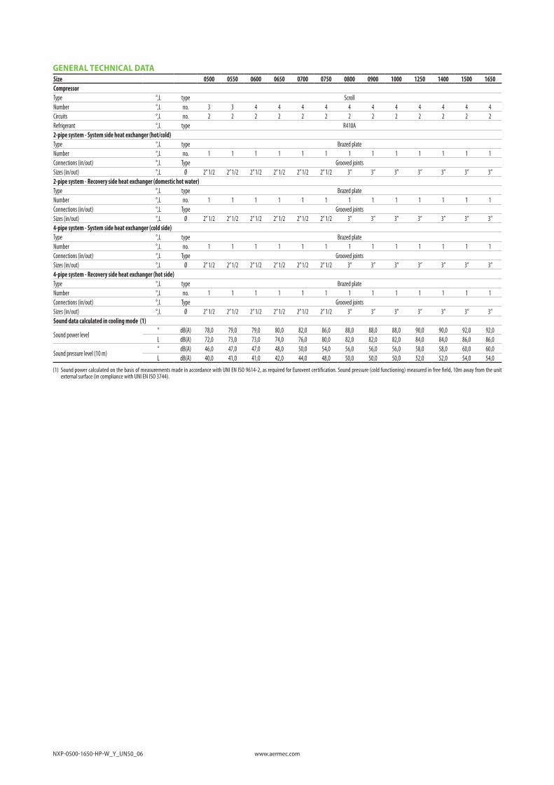
GENERAL TECHNICAL DATASize 0500 0550 0600 0650 0700 0750 0800 0900 1000 1250 1400 1500 1650CompressorType °,L type ScrollNumber °,L no. 3 3 4 4 4 4 4 4 4 4 4 4 4Circuits °,L no. 2 2 2 2 2 2 2 2 2 2 2 2 2Refrigerant °,L type R410A2-pipe system - System side heat exchanger (hot/cold)Type °,L type Brazed plateNumber °,L no. 1 1 1 1 1 1 1 1 1 1 1 1 1Connections (in/out) °,L Type Grooved jointsSizes (in/out) °,L Ø 2” 1/2 2” 1/2 2” 1/2 2” 1/2 2” 1/2 2” 1/2 3” 3” 3” 3” 3” 3” 3”2-pipe system - Recovery side heat exchanger (domestic hot water)Type °,L type Brazed plateNumber °,L no. 1 1 1 1 1 1 1 1 1 1 1 1 1Connections (in/out) °,L Type Grooved jointsSizes (in/out) °,L Ø 2” 1/2 2” 1/2 2” 1/2 2” 1/2 2” 1/2 2” 1/2 3” 3” 3” 3” 3” 3” 3”4-pipe system - System side heat exchanger (cold side)Type °,L type Brazed plateNumber °,L no. 1 1 1 1 1 1 1 1 1 1 1 1 1Connections (in/out) °,L Type Grooved jointsSizes (in/out) °,L Ø 2” 1/2 2” 1/2 2” 1/2 2” 1/2 2” 1/2 2” 1/2 3” 3” 3” 3” 3” 3” 3”4-pipe system - Recovery side heat exchanger (hot side)Type °,L type Brazed plateNumber °,L no. 1 1 1 1 1 1 1 1 1 1 1 1 1Connections (in/out) °,L Type Grooved jointsSizes (in/out) °,L Ø 2” 1/2 2” 1/2 2” 1/2 2” 1/2 2” 1/2 2” 1/2 3” 3” 3” 3” 3” 3” 3”Sound data calculated in cooling mode (1)
Sound power level° dB(A) 78,0 79,0 79,0 80,0 82,0 86,0 88,0 88,0 88,0 90,0 90,0 92,0 92,0L dB(A) 72,0 73,0 73,0 74,0 76,0 80,0 82,0 82,0 82,0 84,0 84,0 86,0 86,0
Sound pressure level (10 m)° dB(A) 46,0 47,0 47,0 48,0 50,0 54,0 56,0 56,0 56,0 58,0 58,0 60,0 60,0L dB(A) 40,0 41,0 41,0 42,0 44,0 48,0 50,0 50,0 50,0 52,0 52,0 54,0 54,0
(1) Sound power calculated on the basis of measurements made in accordance with UNI EN ISO 9614-2, as required for Eurovent certification. Sound pressure (cold functioning) measured in free field, 10m away from the unit external surface (in compliance with UNI EN ISO 3744).

www.aermec.com NXP-0500-1650-HP-W_Y_UN50_06
DIMENSIONS
A
B
C
Size 0500 0550 0600 0650 0700 0750 0800 0900 1000 1250 1400 1500 1650Dimensions and weights
A° mm 1976 1976 1976 1976 1976 1976 2021 2021 2021 2021 2021 2021 2021L mm 2120 2120 2120 2120 2120 2120 2120 2120 2120 2120 2120 2120 2120
B °,L mm 1250 1250 1250 1250 1250 1250 1250 1250 1250 1250 1250 1250 1250C °,L mm 2600 2600 2600 2600 2600 2600 2600 2600 2600 2600 2600 2600 2600Dimensions and weights with pump/s
A° mm 1976 1976 1976 1976 1976 1976 2021 2021 2021 2021 2021 2021 2021L mm 2120 2120 2120 2120 2120 2120 2120 2120 2120 2120 2120 2120 2120
B °,L mm 1250 1250 1250 1250 1250 1250 1250 1250 1250 1250 1250 1250 1250
C° mm 3452 3452 3452 3452 3452 3452 3452 3452 3750 3750 3750 3750 3750L mm 3452 3452 3452 3452 3452 3750 3750 3750 3750 3750 2600 2600 2600
Version
Integrated hydronic kit, user side
Integrated hydronic kit, recovery side
0500 0550 0600 0650 0700 0750 0800 0900 1000 1250 1400 1500 1650
Empty weight
° ° ° kg 990 1000 1110 1130 1180 1380 1680 1700 1890 1960 2060 2100 2270° ° U/V kg 1230 1240 1360 1380 1450 1690 1960 2060 2310 2380 2500 2540 2720° M/N °/U/V kg 1230 1240 1360 1380 1450 1690 1960 2060 2310 2380 2500 2540 2720° °/M/N W/Z kg 1340 1350 1490 1500 1600 1880 2110 2300 2560 2630 2770 2810 3010° O/P °/U/V/W/Z kg 1340 1350 1490 1500 1600 1880 2110 2300 2560 2630 2770 2810 3010L ° ° kg 1230 1230 1340 1360 1420 1570 1910 1930 2120 2190 2270 2400 2500L ° U/V kg 1560 1570 1690 1710 1780 2020 2290 2390 2660 2730 2850 2890 3070L M/N °/U/V kg 1560 1570 1690 1710 1780 2020 2290 2390 2660 2730 2850 2890 3070L °/M/N W/Z kg 1670 1680 1820 1830 1930 2210 2240 2630 2910 2980 3120 3160 3360L O/P °/U/V/W/Z kg 1670 1680 1820 1830 1930 2210 2240 2630 2910 2980 3120 3160 3360
Aermec S.p.A.Via Roma, 996 - 37040 Bevilacqua (VR) - ItaliaTel. 0442633111 - Telefax 044293577www.aermec.com
All data is subject to change without notice. Aermec does not assume Aermec reserves the right to make any modi�cations deemed necessary.
responsibility or liability for errors or omissions.