nx 1899 series release notes · • nx supports the shank as well as the holder when calculating...
TRANSCRIPT

Welcome to NX
March 2020
Dear Customer:
We are proud to introduce the latest release of our product development solution. With this
release, we continue to provide innovative ways to deliver solutions that meet the next generation
of your product design, development, and manufacturing challenges. The new version of NX is
robust and powerful, and it delivers advanced technologies for product design, development, and
manufacturing in a single, multidisciplinary platform. It preserves best-in-class customer
deployment readiness and builds on the productivity and stability achievements of the previous
release.
Sincerely,
Siemens Digital Industries Software
NX 1899 Series – Release Notes
CONTENTS Note .............................................................................................................................................................. 4
NX 1899 Series Summary .............................................................................................................................. 5
Release Availability ................................................................................................................................... 5
Release Content ........................................................................................................................................ 5
NX 1911 ......................................................................................................................................................... 6
1911 UPDATES .......................................................................................................................................... 6
1911 FIXED PROBLEM REPORTS ................................................................................................................ 6
1911 ENHANCEMENTS .............................................................................................................................. 6
CAM : Non-cutting moves in Rest Milling operations ........................................................................... 7
CAM : Report Shortest Tool Enhancements ......................................................................................... 8
NX 1907 ....................................................................................................................................................... 10
1907 UPDATES ........................................................................................................................................ 10
1907 FIXED PROBLEM REPORTS .............................................................................................................. 11
1907 ENHANCEMENTS ............................................................................................................................ 11
NX 1904 ....................................................................................................................................................... 12
1904 UPDATES ........................................................................................................................................ 12
1904 FIXED PROBLEM REPORTS .............................................................................................................. 12
1904 ENHANCEMENTS ............................................................................................................................ 12
NX 1903 ....................................................................................................................................................... 13
1903 UPDATES ........................................................................................................................................ 13
1903 FIXED PROBLEM REPORTS .............................................................................................................. 13
1903 ENHANCEMENTS ............................................................................................................................ 13
Teamcenter Integration: Support for Mentor Graphics Capital Integration ...................................... 14
Architecture: NX Virtual Reality enhancements ................................................................................. 15
CMM: Multiple Curve Segments for Curve Scan ................................................................................. 17
Line Designer: Native Mode Support .................................................................................................. 17
CAE: Pre/Post for Ansys ...................................................................................................................... 26
NX Release Summaries ............................................................................................................................... 30
1911 .................................................................................................................................................... 30
1907 .................................................................................................................................................... 31
1904 .................................................................................................................................................... 32
1903 .................................................................................................................................................... 32

Global Technical Access Center .................................................................................................................. 34
Installation Assistance............................................................................................................................. 34

NOTE
These release notes provide information about updates, fixes, and enhancements that are included in
NX Releases.
For all other Siemens Digital Industries Software product updates, please refer to each products’ respective release notes provided in Documentation Center.

NX 1899 SERIES SUMMARY
Release Availability A complete list of NX 1899 Series releases is included below.
Release Release Date Automatic Update FTP Server
1911 Mar 2020 1907 Feb 2020 1904 Feb 2020 1903 Jan 2020
Release Content The following table represents a release overview of the PR and ER fix counts. More details can be found
in the NX Release Summaries section in this document.
Release PR Count ER Count Total
1911 41 0 41
1907 48 0 48
1904 1 0 1
1903 88 1 89
Total 178 1 179
NX 1911
1911 UPDATES
Caveats
Removed fields feature toggle for Lattice and Rod Thickness
Create a lattice with a variable rod diameter functionality was under a feature toggle in
“Fields_AvailableForLatticeRodDiameter” in NX1899. This feature toggle is removed, and the
functionality is available with no feature toggle in NX1911.
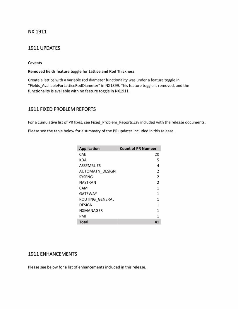
1911 FIXED PROBLEM REPORTS
For a cumulative list of PR fixes, see Fixed_Problem_Reports.csv included with the release documents.
Please see the table below for a summary of the PR updates included in this release.
Application Count of PR Number
CAE 20
KDA 5
ASSEMBLIES 4
AUTOMATN_DESIGN 2
SYSENG 2
NASTRAN 2
CAM 1
GATEWAY 1
ROUTING_GENERAL 1
DESIGN 1
NXMANAGER 1
PMI 1
Total 41
1911 ENHANCEMENTS
Please see below for a list of enhancements included in this release.
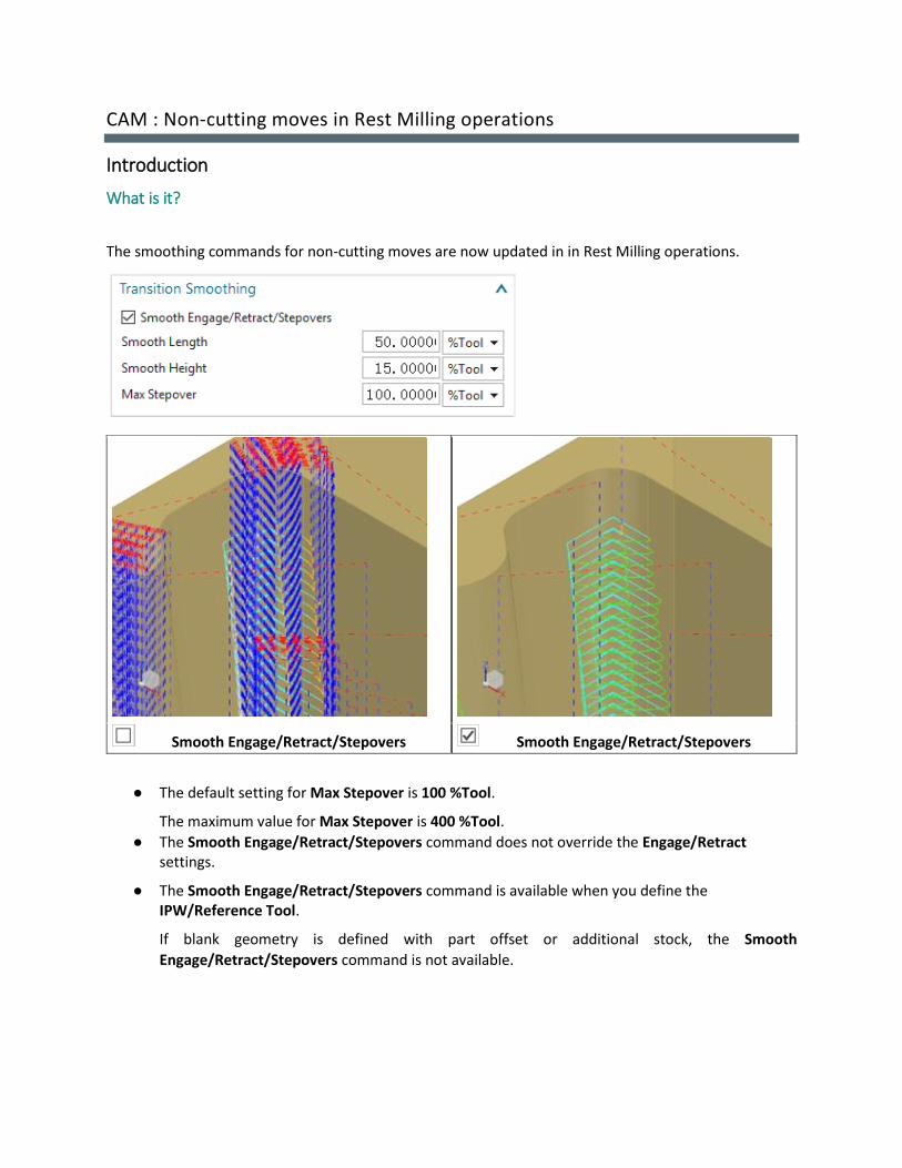
CAM : Non-cutting moves in Rest Milling operations
Introduction
What is it?
The smoothing commands for non-cutting moves are now updated in in Rest Milling operations.
Smooth Engage/Retract/Stepovers Smooth Engage/Retract/Stepovers
● The default setting for Max Stepover is 100 %Tool.
The maximum value for Max Stepover is 400 %Tool.
● The Smooth Engage/Retract/Stepovers command does not override the Engage/Retract settings.
● The Smooth Engage/Retract/Stepovers command is available when you define the IPW/Reference Tool.
If blank geometry is defined with part offset or additional stock, the Smooth
Engage/Retract/Stepovers command is not available.

Where do I find it?
Application Manufacturing
Dialog box Non Cutting Moves node→Smoothing→Transition Smoothing→ Smooth Engage/Retract/Stepovers
CAM : Report Shortest Tool Enhancements
Introduction
What is it?
The Report Shortest Tool command has the following enhancements:
• NX supports the shank as well as the holder when calculating the shortest tool length. • NX considers the holder and shank clearance when calculating the shortest tool length. • When both the holder and shank are defined for a tool, NX reports the shortest tool that
satisfies both the holder and shank clearance values. • Changing the Tool Insertion offset value does not affect the shortest tool value.
In all cases, NX rounds up the reported value to 1 decimal point for metric parts and 2 decimal points for inch parts. For example:
• 120.206 mm = 120.3 mm • 30.206 in = 30.21 in
Note:
The Minimum Tool Length command is renamed to Report Shortest Tool. When you customize a dialog box, the customizable item is also renamed from Minimum Tool Length to Report Shortest Tool.
Where do I find it?
Application Manufacturing
Initial Release NX 1911
Prerequisite Cavity Mill, Adaptive Milling, Plunge Milling, or Rest Milling operation

The tool used in the operation must have a shank or holder defined.
The operation must have a generated tool path.
Operation Navigator Right-click the operation→Tool Path→Report Shortest Tool

NX 1907
1907 UPDATES
Caveats
Bolt Connection Element Error
An error will be raised upon attempting to create a Bolt Connection Element from the Connection Element
Manager dialog under these conditions.
1. A new FEM/AFM file is created and saved in Simcenter 3D 2020.1 version 1907 and it is opened
in Simcenter 3D 2020 version 1899
2. A Bolt Connection element is created in Simcenter 3D 2020.1 version 1907 FEM/AFM file, when
opening the file in Simcenter 3D 2020.1 version 1899, editing the Bolt Connection Element can
trigger the error and obstruct the edit operation
The influence of the errors raised in the above-mentioned cases on further operations in the Simcenter
3D is not known, so for safety reasons it is recommended to close the session and reopen Simcenter 3D
after the error is triggered.
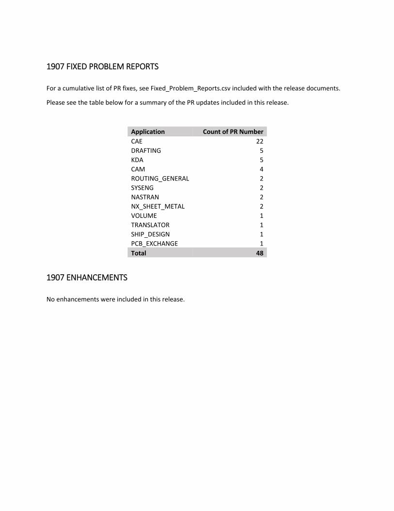
1907 FIXED PROBLEM REPORTS
For a cumulative list of PR fixes, see Fixed_Problem_Reports.csv included with the release documents.
Please see the table below for a summary of the PR updates included in this release.
Application Count of PR Number
CAE 22
DRAFTING 5
KDA 5
CAM 4
ROUTING_GENERAL 2
SYSENG 2
NASTRAN 2
NX_SHEET_METAL 2
VOLUME 1
TRANSLATOR 1
SHIP_DESIGN 1
PCB_EXCHANGE 1
Total 48
1907 ENHANCEMENTS
No enhancements were included in this release.
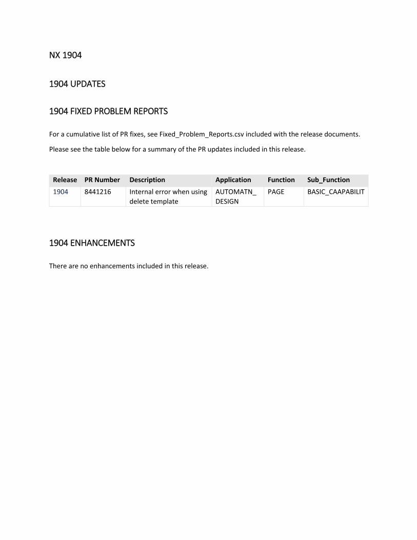
NX 1904
1904 UPDATES
1904 FIXED PROBLEM REPORTS
For a cumulative list of PR fixes, see Fixed_Problem_Reports.csv included with the release documents.
Please see the table below for a summary of the PR updates included in this release.
Release PR Number Description Application Function Sub_Function
1904 8441216 Internal error when using
delete template
AUTOMATN_
DESIGN
PAGE BASIC_CAAPABILIT
1904 ENHANCEMENTS
There are no enhancements included in this release.
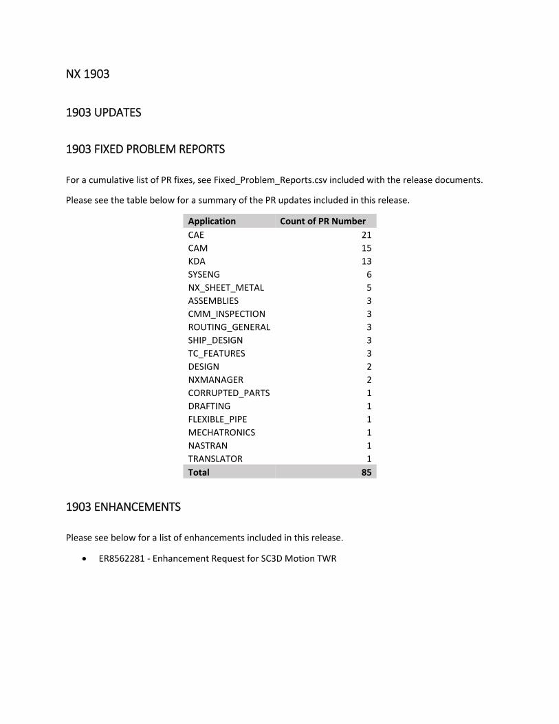
NX 1903
1903 UPDATES
1903 FIXED PROBLEM REPORTS
For a cumulative list of PR fixes, see Fixed_Problem_Reports.csv included with the release documents.
Please see the table below for a summary of the PR updates included in this release.
Application Count of PR Number
CAE 21
CAM 15
KDA 13
SYSENG 6
NX_SHEET_METAL 5
ASSEMBLIES 3
CMM_INSPECTION 3
ROUTING_GENERAL 3
SHIP_DESIGN 3
TC_FEATURES 3
DESIGN 2
NXMANAGER 2
CORRUPTED_PARTS 1
DRAFTING 1
FLEXIBLE_PIPE 1
MECHATRONICS 1
NASTRAN 1
TRANSLATOR 1
Total 85
1903 ENHANCEMENTS
Please see below for a list of enhancements included in this release.
• ER8562281 - Enhancement Request for SC3D Motion TWR

Teamcenter Integration: Support for Mentor Graphics Capital Integration
Introduction
Enhancement Scope
Mentor Graphics Capital software can communicate to NX using connected mode. This requires the two
software to be running simultaneously on same machine or two different machines.
Earlier, the connected mode setup was a part of Capital build and the user had to manually set the
environment in order to get that working. With this enhancement, we will ship the connected mode
package as a part of NX kits thereby not requiring any need for manual setup
Setup Improvements
As mentioned above, earlier connected mode was established by setting the following environment
variables:
• MGLS_PKGINFO_FILE
• MGLS_DLL
• CAPITAL_NX_PLUGIN_LOCATION
• PATH=%PATH%, <Path_To>/jetinitheap.dll
With this enhancement, these values will be set at the time of NX install and the user will no longer need
to set these values manually.
Newly Added Buttons
As part of enhancement, we have added two new buttons under Route List application
1. Connect: On click of this button, an RMI connection is established which enables the exchange
of route list and diagram data between NX and Capital.
2. Harness 2D View: On click of this button, the diagram selected in Capital is displayed for cross-
probing of routing objects

Above buttons will always be visible in NX regardless of whether Customer has Capital software installed
or not. They will work only when the Capital software is running.
Architecture: NX Virtual Reality enhancements
Introduction
Conversing in a multi-user collaborative VR session
All the participants in a multi-user collaborative VR session can speak and hear simultaneously through
the Head Mounted Device (HMD). NX VR integrated audio also supports spatial sound which helps you
hear other participants relative to their position in a 3D space.
You can control the NX VR audio settings from the Audio tab of the Global Menu.
Global Menu
Options Description
Input Source Lists all the supported and enabled microphone
sources that are available on the system.
Point the right controller laser to the list and select the
microphone that you want to use.
To adjust the volume of the audio recording device,
point the right control to or , and press and
hold the laser trigger. You must release the laser
trigger to stop the volume adjustment.
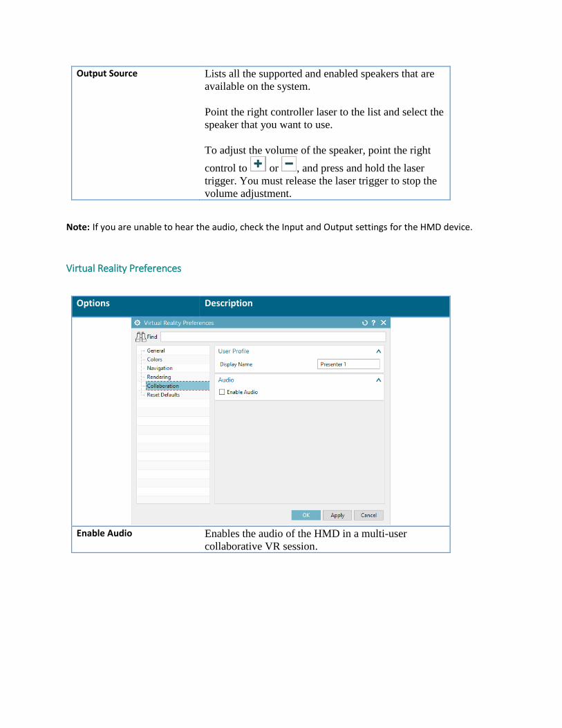
Output Source Lists all the supported and enabled speakers that are
available on the system.
Point the right controller laser to the list and select the
speaker that you want to use.
To adjust the volume of the speaker, point the right
control to or , and press and hold the laser
trigger. You must release the laser trigger to stop the
volume adjustment.
Note: If you are unable to hear the audio, check the Input and Output settings for the HMD device.
Virtual Reality Preferences
Options Description
Enable Audio Enables the audio of the HMD in a multi-user
collaborative VR session.
CMM: Multiple Curve Segments for Curve Scan
Introduction
CMM Inspection – Path Dialog – Curve Scans When programming curve scans the user can define scan parameters such as scan speed at each control
point. In NX1903, the user has two new ways to define the control points:
- Midpoint of curve
- Screen select point on curve
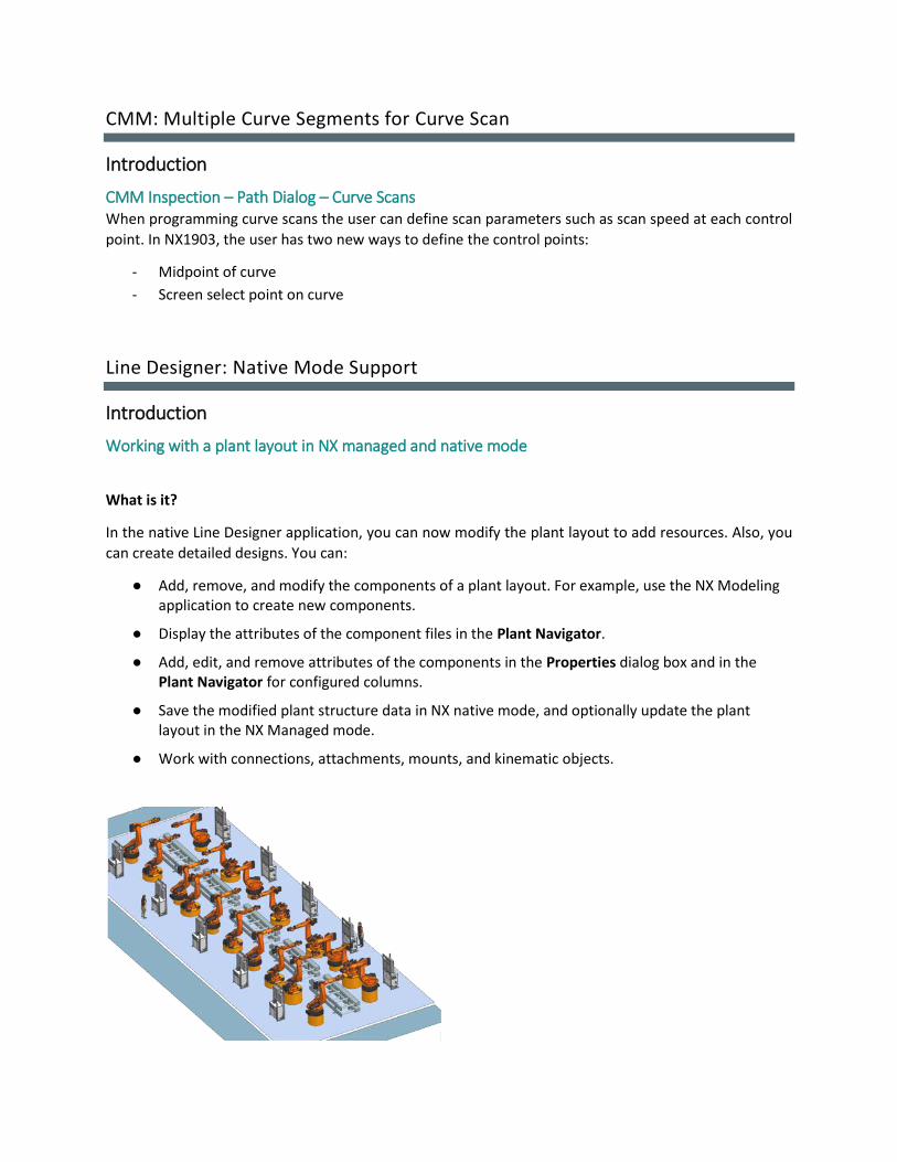
Line Designer: Native Mode Support
Introduction
Working with a plant layout in NX managed and native mode
What is it?
In the native Line Designer application, you can now modify the plant layout to add resources. Also, you
can create detailed designs. You can:
● Add, remove, and modify the components of a plant layout. For example, use the NX Modeling application to create new components.
● Display the attributes of the component files in the Plant Navigator.
● Add, edit, and remove attributes of the components in the Properties dialog box and in the Plant Navigator for configured columns.
● Save the modified plant structure data in NX native mode, and optionally update the plant layout in the NX Managed mode.
● Work with connections, attachments, mounts, and kinematic objects.

Why should I use it?
You can now author Line Designer plant layouts in NX native.
Where do I find it?
Application Line Designer
Resource bar File tab→Export Assembly outside Teamcenter
File tab→Import Assembly into Teamcenter
Technical documentation
Managing a plant layout in NX managed and native mode
Exporting and importing a plant layout
For various business processes and customer requirements, and for general product development, you
need to move the plant layout from one database to another. This helps you to conveniently provide
required data to a third party for further modifications. To do this, use the Export Assembly outside
Teamcenter command.
You can modify and detail the plant layout and add, remove, modify, rename, and revise its components
in NX native mode.
Once you modify the plant layout, you can import back this data into NX integrated with the Teamcenter
environment. To do this, use the Import Assembly into Teamcenter command. You can verify and validate
the changes to the plant layoutfixture data.
You can move the plant layout data in the following way:
Export Assembly outside Teamcenter
In NX integrated with Teamcenter, you can launch the Plant Navigator and load a plant layout. Before you export the plant layout data, make sure that you do the following:
● Save the plant layout data in Line Designer before you export the data, with or without any changes.
● Confirm that the plant layout data contains part files for all the objects. This is necessary so that Line Designer in the native mode recognizes these objects in the Plant Navigator.
● Use the mapping file to map the object properties to the part file. You can use this mapping file in the NX native mode and show more

information to the native user. To do this, use the attribute mapping tool.
For more information, see Export Assembly outside Teamcenter Overview in NX help.
Import Assembly into Teamcenter
Import the modified plant layout data to NX integrated with Teamcenter. This helps you to validate the plant layout with a detailed plan and to check for the modified data. For more information, see Import Assembly into Teamcenter in NX help.
If the plant layout data contains the JT parts as components, you can export them to NX native in the local directory and import them back in NX integrated with Teamcenter. NX exports the JT parts as components in the plant layout. For more information, see Importing and exporting Multi-CAD in NX help.
Where do I find it?
Application Line Designer
Resource bar File tab→Export Assembly outside Teamcenter
File tab→Import Assembly into Teamcenter

Managing plant layout data from NX managed to NX native
The following graphic shows a typical workflow for exporting the plant layout data from NX integrated
with Teamcenter (Managed) mode to the native NX mode and importing back to managed NX mode.

Managing plant layout data in NX native
The following graphic shows a typical workflow for working with a plant layout in NX native mode.
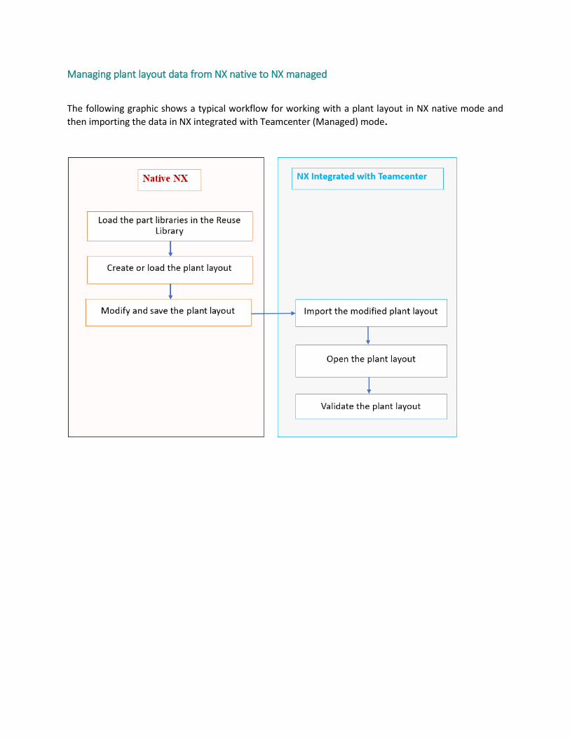
Managing plant layout data from NX native to NX managed
The following graphic shows a typical workflow for working with a plant layout in NX native mode and
then importing the data in NX integrated with Teamcenter (Managed) mode.

Managing PAX files for NX Native
A PAX file is actually a palette file with a .pax extension. A palette file is an XML file that contains a list of
palette entries, each of which contains a specific identification number and a standard set of data that
describes the entry.
You can create structure and resource objects that you can load in Teamcenter as a specific Item Type.
The pax file for a work area template in Line Designer is named ugs_linedesigner_workarea_templates.pax
and for the resource templates is named ugs_linedesigner_templates.pax.
The following is an example of the XML in a .pax file that defines the template for the new work area. The
type specified in the object data section is mapped to the Item Type in Teamcenter, which you can use
while importing layout data to Teamcenter.
You can customize the pax files to achieve the work area and resource types you want, regardless of the
listed work areas and resources below.
Supported work areas
By default, these work areas are available to use in NX native:
• Workarea
• Plant
• Site
• Department
• Line
• Zone
• Station
• Blank (Custom)
Supported resource templates
By default, these resource templates are available to use in NX native:
• Equipment
• Resource
• Conveyor
• Robot
• Factory Tool
• Cable Resources
• Sensors
• Fixture Root
• Blank (Custom)
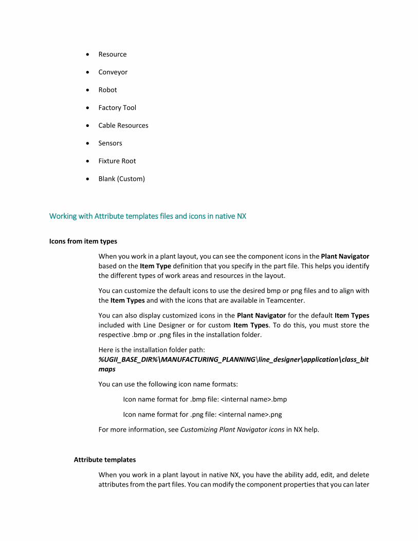
Working with Attribute templates files and icons in native NX
Icons from item types
When you work in a plant layout, you can see the component icons in the Plant Navigator
based on the Item Type definition that you specify in the part file. This helps you identify
the different types of work areas and resources in the layout.
You can customize the default icons to use the desired bmp or png files and to align with
the Item Types and with the icons that are available in Teamcenter.
You can also display customized icons in the Plant Navigator for the default Item Types
included with Line Designer or for custom Item Types. To do this, you must store the
respective .bmp or .png files in the installation folder.
Here is the installation folder path:
%UGII_BASE_DIR%\MANUFACTURING_PLANNING\line_designer\application\class_bit
maps
You can use the following icon name formats:
Icon name format for .bmp file: <internal name>.bmp
Icon name format for .png file: <internal name>.png
For more information, see Customizing Plant Navigator icons in NX help.
Attribute templates
When you work in a plant layout in native NX, you have the ability add, edit, and delete
attributes from the part files. You can modify the component properties that you can later

import to Teamcenter, if required. You can edit the attributes of a component in the
Properties dialog box and in the Plant Navigator for configured columns.
For NX native mode, you can use the attributes based on the default Teamcenter Item
Types and the attribute mapping file from the default Line Designer installation. When
you create a New Item, NX includes the component properties in the part file. You can
find the Attribute Templates that you use to add component properties in the attribute
templates folder.
Here is the attribute templates folder path:
%UGII_BASE_DIR%\MANUFACTURING_PLANNING\line_designer\startup\pdm_attribu
te_templates
The Attribute Templates are based on the attribute mappings that you define in
Teamcenter. You can export these templates from NX and customize them. For more
information, see Attribute templates in NX help. For detailed information about the mapping file, see Mapping Attributes in Teamcenter
and Teamcenter Integration in NX help.
Modifying the plant layout in NX native
To align with changing customer requirements, you might need to frequently change the design of a plant
layout. This helps you create new designs, develop new products, and stay current in the market.
You can modify the plant layout to add components. Also, you can create detailed designs. To do this, you
can use the Line Designer in NX native mode.
You can export the plant layout from NX managed mode to the NX native mode and load the whole plant
layout structure.
When you load the plant layout data in NX native, you can:
● Add, remove, and modify the components of a plant layout. For example, use the NX Modeling application to create new components.
● Display the attributes of the component files in the Plant Navigator.
● Add, edit, and remove attributes of the components using the Properties dialog box and in the Plant Navigator for configured columns.
● Save the modified plant structure data in NX native mode, and optionally update the plant layout in the NX Managed mode.
Work with connections, attachments, mounts, and kinematic objects.
CAE: Pre/Post for Ansys
Introduction
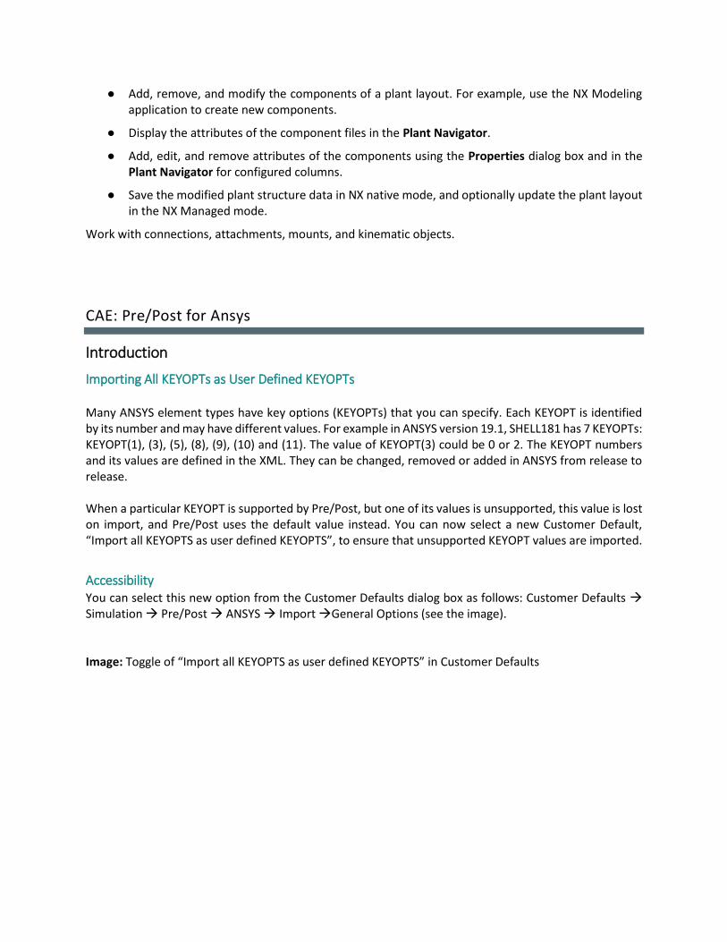
Importing All KEYOPTs as User Defined KEYOPTs
Many ANSYS element types have key options (KEYOPTs) that you can specify. Each KEYOPT is identified by its number and may have different values. For example in ANSYS version 19.1, SHELL181 has 7 KEYOPTs: KEYOPT(1), (3), (5), (8), (9), (10) and (11). The value of KEYOPT(3) could be 0 or 2. The KEYOPT numbers and its values are defined in the XML. They can be changed, removed or added in ANSYS from release to release. When a particular KEYOPT is supported by Pre/Post, but one of its values is unsupported, this value is lost on import, and Pre/Post uses the default value instead. You can now select a new Customer Default, “Import all KEYOPTS as user defined KEYOPTS”, to ensure that unsupported KEYOPT values are imported.
Accessibility You can select this new option from the Customer Defaults dialog box as follows: Customer Defaults → Simulation → Pre/Post → ANSYS → Import →General Options (see the image). Image: Toggle of “Import all KEYOPTS as user defined KEYOPTS” in Customer Defaults

Import behavior
How Pre/Post imports KEYOPTs in an ANSYS input file depends on whether the new customer default is
selected:
• When the new default is turned off, Pre/Post imports KEYOPTs into Pre/Post as in previous releases.
• When the new default is selected, Pre/Post imports all KEYOPTs as User Defined KEYOPTs.
The following images illustrate these two behaviors:
Image: KEYOPTs numbers and values example for SOLID186 with an unsupported value in the input file
Image: SOLID186 ET modeling object with the loss of unsupported value when the customer default is
turned off

Image: SOLID186 ET modeling object when the customer default is selected
Note: This support applies to all element types accept the Legacy Elements that are not supported as user
defined KEYOPTS. The Legacy Elements are BEAM4, BEAM44, LINK8, LINK10, CONTAC12, CONTAC52,
PLANE42, PLANE82, SHELL63, SHELL57, SHELL91, SHELL93, SHELL99, SOLID45, SOLID92, SOLID95,

SOLID191. Pre/Post always imports the KEYOPTs for these Legacy Elements as standard KEYOPTs regadless
the status of the new default.
Image: SOLID95 ET modeling object (Legacy Element)
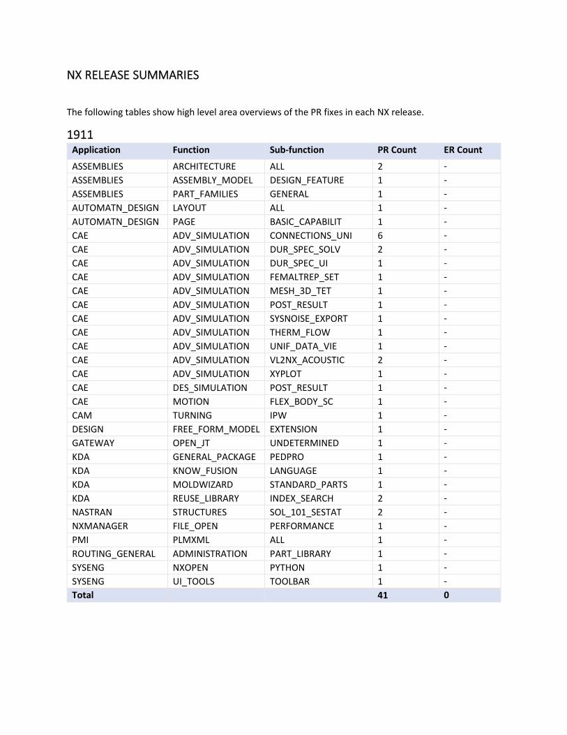
NX RELEASE SUMMARIES
The following tables show high level area overviews of the PR fixes in each NX release.
1911 Application Function Sub-function PR Count ER Count
ASSEMBLIES ARCHITECTURE ALL 2 -
ASSEMBLIES ASSEMBLY_MODEL DESIGN_FEATURE 1 -
ASSEMBLIES PART_FAMILIES GENERAL 1 -
AUTOMATN_DESIGN LAYOUT ALL 1 -
AUTOMATN_DESIGN PAGE BASIC_CAPABILIT 1 -
CAE ADV_SIMULATION CONNECTIONS_UNI 6 -
CAE ADV_SIMULATION DUR_SPEC_SOLV 2 -
CAE ADV_SIMULATION DUR_SPEC_UI 1 -
CAE ADV_SIMULATION FEMALTREP_SET 1 -
CAE ADV_SIMULATION MESH_3D_TET 1 -
CAE ADV_SIMULATION POST_RESULT 1 -
CAE ADV_SIMULATION SYSNOISE_EXPORT 1 -
CAE ADV_SIMULATION THERM_FLOW 1 -
CAE ADV_SIMULATION UNIF_DATA_VIE 1 -
CAE ADV_SIMULATION VL2NX_ACOUSTIC 2 -
CAE ADV_SIMULATION XYPLOT 1 -
CAE DES_SIMULATION POST_RESULT 1 -
CAE MOTION FLEX_BODY_SC 1 -
CAM TURNING IPW 1 -
DESIGN FREE_FORM_MODEL EXTENSION 1 -
GATEWAY OPEN_JT UNDETERMINED 1 -
KDA GENERAL_PACKAGE PEDPRO 1 -
KDA KNOW_FUSION LANGUAGE 1 -
KDA MOLDWIZARD STANDARD_PARTS 1 -
KDA REUSE_LIBRARY INDEX_SEARCH 2 -
NASTRAN STRUCTURES SOL_101_SESTAT 2 -
NXMANAGER FILE_OPEN PERFORMANCE 1 -
PMI PLMXML ALL 1 -
ROUTING_GENERAL ADMINISTRATION PART_LIBRARY 1 -
SYSENG NXOPEN PYTHON 1 -
SYSENG UI_TOOLS TOOLBAR 1 -
Total 41 0

1907 Application Function Sub-function PR Count ER Count
CAE ADV_SIMULATION CONNECTIONS_UNI 6 -
CAE ADV_SIMULATION DUR_SPEC_SOLV 1 -
CAE ADV_SIMULATION FEM_CORRELATION 1 -
CAE ADV_SIMULATION FIELDS 2 -
CAE ADV_SIMULATION MATERIALS 1 -
CAE ADV_SIMULATION MESH_MATING 1 -
CAE ADV_SIMULATION SAMCEF_EXPORT 1 -
CAE ADV_SIMULATION SELECTION_RECIP 1 -
CAE ADV_SIMULATION THERM_FLOW 1 -
CAE ADV_SIMULATION UNIF_DATA_VIE 1 -
CAE ADV_SIMULATION VL2NX_ACOUSTIC 2 -
CAE MOTION FUNCTION_EDITOR 2 -
CAE MOTION LINK 1 -
CAE MOTION SOLVER_LMS 1 -
CAM FLOOR_WALL_MILL CONTAINMENT 1 -
CAM FLOOR_WALL_MILL NON_CUT_MOVES 1 -
CAM TEMPLATES DEFAULTS 1 -
CAM TOOL_PATH LIST 1 -
DRAFTING SYMBOL CUSTOM_SYMBOL 4 -
DRAFTING SYMBOL REUSE_LIBRARY 1 -
KDA MOLDED_PART_VAL FLOW_ANALYSIS 1 -
KDA MOLDWIZARD CREATE_POCKETS 1 -
KDA MOLDWIZARD LOAD_PRODUCT 1 -
KDA VALIDATION TC_INTEG 1 -
KDA WELD_ASSISTANT TRANSFORM 1 -
NASTRAN STRUCTURES SOL_101_SESTAT 2 -
NX_SHEET_METAL 3_BEND_CORNER ALL 1 -
NX_SHEET_METAL CLOSED_CORNER ALL 1 -
PCB_EXCHANGE IDX_IMPORT ALL 1 -
ROUTING_GENERAL CONSTRAINTS GENERAL 1 -
ROUTING_GENERAL LEGACY_STOCK INSERT_STOCK 1 -
SHIP_DESIGN STEEL_FEATURES MIRROR_COPY 1 -
SYSENG NXOPEN LICENSING 1 -
SYSENG UI_TOOLS COMMAND_FINDER 1 -
TRANSLATOR STEP_AP214 STEP_TO_UG 1 -
VOLUME VOLUME_ACCESS ALL 1 -
Total 48 0

1904 Application Function Sub-function PR Count ER Count
AUTOMATN_DESIGN PAGE BASIC_CAPABILIT 1 -
Total 1 0
1903 Application Function Sub-function PR Count ER Count
ASSEMBLIES SEQUENCING MOTION 2 -
ASSEMBLIES WEIGHT_MANAGE ALL 1 -
CAE ADV_SIMULATION CHK_ELEMENTS 1 -
CAE ADV_SIMULATION DURABILITY 1 -
CAE ADV_SIMULATION DUR_SPEC_SOLV 1 -
CAE ADV_SIMULATION FILE_OPERATIONS 2 -
CAE ADV_SIMULATION IPRT_MODEL_OPS 1 -
CAE ADV_SIMULATION MATERIALS 1 -
CAE ADV_SIMULATION POST_OTHER 2 -
CAE ADV_SIMULATION POST_RESULT 4 -
CAE ADV_SIMULATION THERM_FLOW 1 -
CAE ADV_SIMULATION UNIVERSAL_FILES 1 -
CAE MOTION CONTACT 1 -
CAE MOTION FORCES 1 -
CAE MOTION FTK 1 -
CAE MOTION TWR - 1
CAE MOTION VL2NXMIGRATION 3 -
CAM POSTPROCESS ALL 2 -
CAM TC_MFG MRL_CONNECT 1 -
CAM TC_MFG OTHER 8 -
CAM TURNING OTHER 2 -
CAM WORK_INSTRUCTN ALL 2 -
CMM_INSPECTION PATH ALL 1 -
CMM_INSPECTION POSTPROCESSING DMIS_30 1 -
CMM_INSPECTION SIMULATION ALL 1 -
CORRUPTED_PARTS KDA ALL 1 -
DESIGN EXPRESSION MEASUREMENTS 1 -
DESIGN UFUNC MODELING 1 -
DRAFTING SHIPBUILDING VIEW_CREATION 1 -
FLEXIBLE_PIPE GENERAL ALL 1 -
KDA PROGRESSIVE_DIE FACE_COLOR_MGT 1 -
KDA PROGRESSIVE_DIE MOTION_SIMULATE 1 -
KDA REUSE_LIBRARY ADD_REUSE_COMP 1 -
KDA WELD_ASSISTANT EASY_SPOT 2 -
KDA WELD_ASSISTANT GROOVE 5 -

KDA WELD_ASSISTANT IMPACT_ANALYSIS 1 -
KDA WELD_ASSISTANT WELD_PT_WIZARD 2 -
MECHATRONICS OPC UA_SERVER 1 -
NASTRAN STRUCTURES SOL_402 1 -
NX_SHEET_METAL FLANGE ALL 1 -
NX_SHEET_METAL FLAT_PATTERN ALL 2 -
NX_SHEET_METAL FLAT_SOLID ALL 1 -
NX_SHEET_METAL PREFERENCES ALL 1 -
NXMANAGER ASSEMBLY UPDATE_STRUCT 1 -
NXMANAGER FILE_OPEN NX_MASTER_PART 1 -
ROUTING_GENERAL CUST_DEFAULTS GENERAL 1 -
ROUTING_GENERAL REUSE_LIBRARY PLACE_PART 1 -
SHIP_DESIGN DRAFTING SHIP_SECTN_DRWG 1 -
SHIP_DESIGN DRAWING_AUTO INVRS_BEND_LINE 2 -
SYSENG CONFIG_UPGRADE ROLES 1 -
SYSENG NXOPEN UDO 1 -
SYSENG SELECTION SNAP_POINT 1 -
SYSENG UG/OPEN UDO 1 -
SYSENG UI_TOOLS ROLES 2 -
SYSTEM WNT_INSTALL ALL 4 -
TC_FEATURES RESOURCE_MGR AUTO_ASSEMBLY 3 -
TRANSLATOR STEP_AP214 ALL 1 -
Total 88 1

GLOBAL TECHNICAL ACCESS CENTER
Installation Assistance For additional installation assistance, or to report any problems, contact the Global Technical Access
Center (GTAC).
Website:
http://support.industrysoftware.automation.siemens.com/gtac.shtml
Phone:
United States and Canada: 800-955-0000 or 714-952-5444
Outside the United States and Canada: Contact your local support office.