nvisible speakers - bose worldwideproducts.bose.com/pdf/customer_service/owners/og_791.pdf · note:...
TRANSCRIPT

Installation Guide
Installationsvejledning
Installationsanleitung
Guía de instalación
Asennusopas
Notice d’installation
Telepítési útmutató
Guida di installazione
Gebruikershandleiding
Podręcznik instalacji
Installationsanvisning
VIRTUALLY INVISIBLE® 791 SPEAKERS
©2009 Bose Corporation, The Mountain,Framingham, MA 01701-9168 USAAM321052 Rev.01
VIRTU
ALLY IN
VISIBLE
® 791 SPEAK
ERS
Covers.fm Page 1 Friday, April 17, 2009 9:51 AM
EnglishTAB 6TAB 8 TAB 7 TAB 3TAB 5 TAB 2TAB 4
01_SafetyInformation.fm Page ii Thursday, June 11, 2009 10:34 AM
SAFETY INFORMATION
Important words of cautionPlease read this owner’s guide completely before you start. Then carefully consider your experience using the tools and taking the precautions referred to here.
If you have doubts about doing this installation, you should contact either the dealer you purchased the product from, an electrician, or a professional audio/video installer. You can describe the job and request a cost estimate before committing to installation service.
WARNING: Installation shall be in accordance with the applicable section of the National Electrical Code, ANSI/NFPA 70, and/or the National Fire Alarm Code, ANSI/NFPA 72, as applicable. The wiring method and compartment shall be such as not to interfere with the operation of the speaker.
CAUTIONS: • Failure to follow the instructions in this owner’s guide voids all
warranties on your speakers.• These speakers are not designed or recommended for
installation in walls, in ceilings of masonry, or in drop ceilings.• This product is not intended for use in Air-Handling Plenum
Spaces.• Consult local building codes before you get started with this
installation.• See product enclosures for safety-related markings.• Make no modifications to the speakers or accessories.
Unauthorized alterations may compromise safety, regulatory compliance, and system performance.
• Be sure to keep all insulation away from speakers in accordance with the installation instructions in this guide.
Mount these speakers in wood frame or similar construction onlyEach speaker requires a round space of 85/8 in. (21.9 cm) diameter, plus a minimum of 41/8 in. (10.5 cm) of depth behind wallboard that is a maximum of 3/4 in. (1.9 cm) thick.
Bose recommends installing these speakers only in wood frame or similar ceiling construction with adequately spaced studs, as found in 2 x 6 construction. These installation guide instructions are specific to this type of installation only.
Important safety instructions1. Read these instructions – for all components before using
this product. 2. Keep these instructions – for future reference.3. Heed all warnings – on the product and in the owner’s guide.4. Follow all instructions.5. Install in accordance with the manufacturer’s instructions.6. Only use attachments/accessories specified by the
manufacturer.
For your recordsSerial numbers are located on the rear of each of your Virtually Invisible® 791 speakers.
Serial numbers: _____________________ ____________________
Serial numbers: _____________________ ____________________
Serial numbers: _____________________ ____________________
Dealer name: ___________________________________________
Dealer phone: ___________________________________________
Purchase date: ___________________________________________
We suggest you keep your sales receipt and warranty card together with this owner’s guide.
VIRTUALLY INVISIBLE is a registered trademark of Bose Corporation in the U.S. and other countries.
ii
TAB 5TAB 4 TAB 6 TAB 8TAB 7English TAB 3TAB 2
02_TOC.fm Page iii Thursday, June 11, 2009 10:36 AM
OVERVIEW AND CONTENTS
Basic steps to installation
The instructions on the pages that follow will help you complete each of the steps below.
Step 1: Choose approximate locations for each speaker.
Step 2: Observe the cautions and use the template for precise placement.
Step 3: Cut the hole for each speaker.
Step 4: Wire each speaker.
Step 5: Insert and secure the speaker in the ceiling.
Step 6: Test each speaker to make sure it works.
PREPARATION 2
Before you begin... . . . . . . . . . . . . . . . . . . . . . . . . 2Unpacking . . . . . . . . . . . . . . . . . . . . . . . . . . . . . 2Other equipment you will need . . . . . . . . . . . . . 2If painting is in your plan . . . . . . . . . . . . . . . . . 2
Selecting speaker cable . . . . . . . . . . . . . . . . . . 3Preparing the cable wires . . . . . . . . . . . . . . . . 3
Placement guidelines . . . . . . . . . . . . . . . . . . . . . . 4Using the arrow as a guide . . . . . . . . . . . . . . . . 4Placing speakers for stereo sound . . . . . . . . . . 4Placing speakers for home theater . . . . . . . . . . 5Other considerations . . . . . . . . . . . . . . . . . . . . . 5
INSTALLATION 6
Preparing the ceiling . . . . . . . . . . . . . . . . . . . . . . 6Using the template . . . . . . . . . . . . . . . . . . . . . . 6Drilling a pilot hole . . . . . . . . . . . . . . . . . . . . . . . 6Cutting the speaker hole . . . . . . . . . . . . . . . . . . 7Getting the wire ready . . . . . . . . . . . . . . . . . . . . 7
Connecting the speaker . . . . . . . . . . . . . . . . . . . . 8
Finishing the installation . . . . . . . . . . . . . . . . . . . 8Securing the speaker . . . . . . . . . . . . . . . . . . . . 8Testing each speaker . . . . . . . . . . . . . . . . . . . . 10Attaching the grille . . . . . . . . . . . . . . . . . . . . . . 10
REFERENCE 11
Painting the exterior parts . . . . . . . . . . . . . . . . . . 11Painting the grille . . . . . . . . . . . . . . . . . . . . . . . 11
Painting the frame . . . . . . . . . . . . . . . . . . . . . . . 12
Troubleshooting . . . . . . . . . . . . . . . . . . . . . . . . . . 13
Customer service . . . . . . . . . . . . . . . . . . . . . . . . . 14
Limited warranty . . . . . . . . . . . . . . . . . . . . . . . . . . 14
Accessories . . . . . . . . . . . . . . . . . . . . . . . . . . . . . 14
Technical information . . . . . . . . . . . . . . . . . . . . . 14
iii
EnglishTAB 6TAB 8 TAB 7 TAB 3TAB 5 TAB 2TAB 4
00_791_Speaker_IG.book Page 2 Wednesday, April 15, 2009 8:33 AM
PREPARATION
Before you begin...Thank you for choosing Bose® Virtually Invisible® 791speakers for in-ceiling installation. These top-of-the-line Virtually Invisible® speakers provide superior perfor-mance for stereo and home theater enjoyment. Their slim profile blends well into your room, so only the sound...not the speakers...stands out.
Please be sure to read this guide carefully before you do any cutting. There are many factors to consider before proceeding with this type of installation.
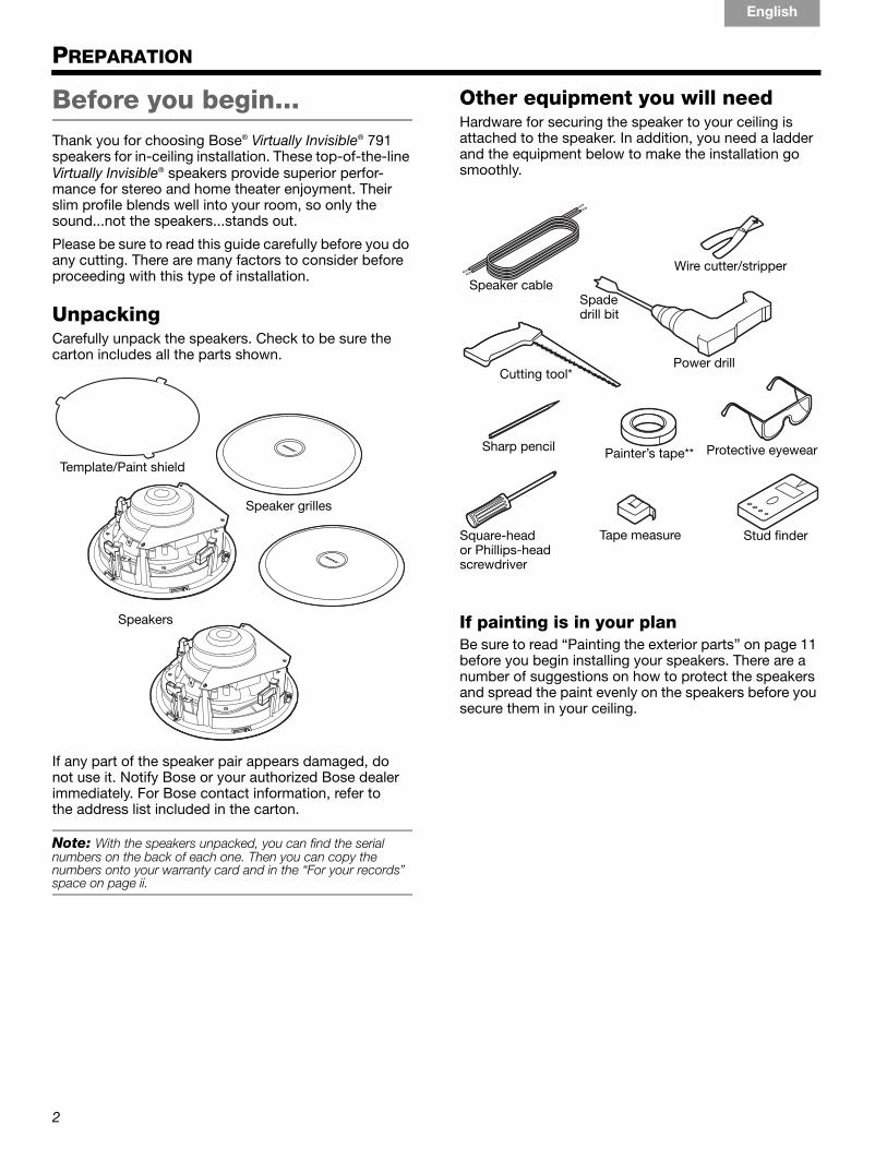
Unpacking Carefully unpack the speakers. Check to be sure the carton includes all the parts shown.
If any part of the speaker pair appears damaged, do not use it. Notify Bose or your authorized Bose dealer immediately. For Bose contact information, refer to the address list included in the carton.
Note: With the speakers unpacked, you can find the serial numbers on the back of each one. Then you can copy thenumbers onto your warranty card and in the “For your records” space on page ii.
Other equipment you will needHardware for securing the speaker to your ceiling is attached to the speaker. In addition, you need a ladder and the equipment below to make the installation go smoothly.
If painting is in your planBe sure to read “Painting the exterior parts” on page 11 before you begin installing your speakers. There are a number of suggestions on how to protect the speakers and spread the paint evenly on the speakers before you secure them in your ceiling.
Speakers
Template/Paint shield
Speaker grilles
Speaker cableSpade drill bit
Square-head or Phillips-head screwdriver
Sharp pencil
Cutting tool*
Protective eyewearPainter’s tape**
Wire cutter/stripper
Tape measure
Power drill
Stud finder
2

PREPARATION
TAB 5TAB 4 TAB 6 TAB 8TAB 7English TAB 3TAB 2
00_791_Speaker_IG.book Page 3 Wednesday, April 15, 2009 8:33 AM
Selecting speaker cableIf your cables are not yet installed, use these guidelines for choosing and using speaker cable. If your cables are already installed, check to be sure they meet these standards.
Consider the location of the speakers and be sure to allow enough cable to reach each one. This includes the extra length needed for wiring the speaker before inserting it into the ceiling.
Preparing the cable wiresSpeaker cable consists of two insulated wires. The insulation around one wire is marked (striped, collared, or ribbed) to identify it as positive. The other wire is negative.
Note: It is sometimes difficult to distinguish wire markings. Inspect both wires carefully.
1. Strip approximately 1/2 in. (13 mm) of insulation from both wires.
2. Twist the bare end of each wire so loose strands will not touch across terminals.
Be sure to connect each wire to the proper speaker terminal, positive to positive (+) and negative to negative (–).
Note: For information on installing cable, consult a professional electrician or audio/video installer, or look for reference books at a local home building retail store.
Gauge Maximum Length
18 AWG (0.82 mm2) 20 ft (6 m)
16 AWG (1.3 mm2) 30 ft (9 m)
14 AWG (2.1 mm2) 50 ft (15 m)
12 AWG (3.3 mm2) 90 ft (27 m)
3

PREPARATION
EnglishTAB 6TAB 8 TAB 7 TAB 3TAB 5 TAB 2TAB 4
03_Preparation.fm Page 4 Thursday, June 11, 2009 10:41 AM
Placement guidelines Orienting and placing these identical speakers is critical to their performance.
Follow these guidelines in choosing the approximate location for each speaker. Before you mark the location for the ceiling holes, be sure to read:
• “Other considerations” on page 5, and
• “WARNINGS:” on page 6.
Using the arrow as a guideThere is a small arrow molded into the inside flange of each speaker. Use it as a guide for orienting the speakers relative to one another.
The diagrams that follow show the proper orientation using a pair of speakers for stereo sound, or several pairs of speakers for home theater sound.
Placing speakers for stereo soundPosition these two speakers:
– one on the left and one on the right at the front of the room
– oriented with the arrow pointing to the opposite speaker
– an equal distance from the primary listening area
– with each one AT LEAST:
- 2 ft (.6 m) from the front wall- 3 ft (1 m) from the side walls- 6 ft (2 m) apart
Guide arrow
3'(1 m)
3'(1 m)
2' (.6 m)2' (.6 m)
2' (.6 m) 2' (.6 m)
Front of your room
Minimum Minimum
Minimum
MinimumMinimum
Minimum
4
PREPARATION
TAB 5TAB 4 TAB 6 TAB 8TAB 7English TAB 3TAB 2
00_791_Speaker_IG.book Page 5 Wednesday, April 15, 2009 8:33 AM
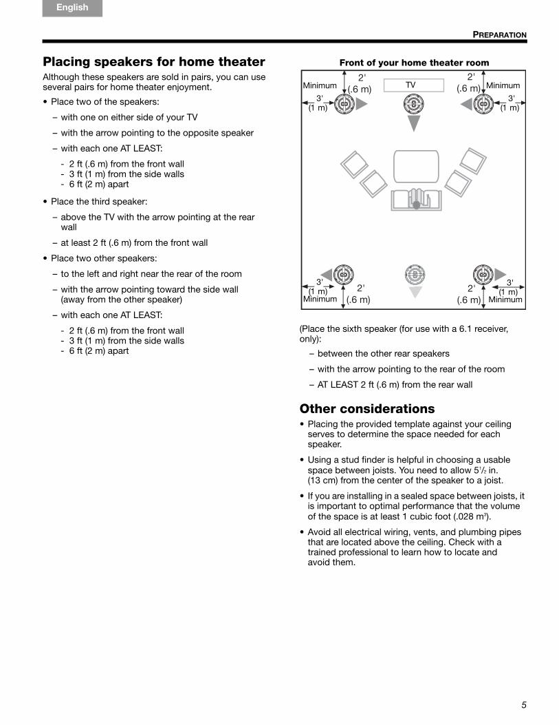
Placing speakers for home theaterAlthough these speakers are sold in pairs, you can use several pairs for home theater enjoyment.
• Place two of the speakers:
– with one on either side of your TV
– with the arrow pointing to the opposite speaker
– with each one AT LEAST:
- 2 ft (.6 m) from the front wall- 3 ft (1 m) from the side walls- 6 ft (2 m) apart
• Place the third speaker:
– above the TV with the arrow pointing at the rear wall
– at least 2 ft (.6 m) from the front wall
• Place two other speakers:
– to the left and right near the rear of the room
– with the arrow pointing toward the side wall (away from the other speaker)
– with each one AT LEAST:
- 2 ft (.6 m) from the front wall- 3 ft (1 m) from the side walls- 6 ft (2 m) apart
(Place the sixth speaker (for use with a 6.1 receiver, only):
– between the other rear speakers
– with the arrow pointing to the rear of the room
– AT LEAST 2 ft (.6 m) from the rear wall
Other considerations• Placing the provided template against your ceiling
serves to determine the space needed for each speaker.
• Using a stud finder is helpful in choosing a usable space between joists. You need to allow 51/2 in. (13 cm) from the center of the speaker to a joist.
• If you are installing in a sealed space between joists, it is important to optimal performance that the volume of the space is at least 1 cubic foot (.028 m3).
• Avoid all electrical wiring, vents, and plumbing pipes that are located above the ceiling. Check with a trained professional to learn how to locate and avoid them.
2' (.6 m)
3'(1 m)
3'(1 m) 2'
(.6 m)
3'(1 m)
3'(1 m)
2' (.6 m)
2' (.6 m)
Front of your home theater room
TV
Minimum
MinimumMinimum
Minimum
5

EnglishTAB 6TAB 8 TAB 7 TAB 3TAB 5 TAB 2TAB 4
04_Installation.fm Page 6 Thursday, April 23, 2009 10:08 AM
INSTALLATION
Preparing the ceilingBe sure you have read and understand all of the safety and preparation information on these pages so you can continue with confidence.
CAUTIONS:• If you are unsure of your ability to complete this
process, contact a professional installer.• Certain forms of insulation (such as horse hair plaster,
newspaper, cellulose, or any blown-in materials) may pose a risk of ignition. Be sure to keep all insulation away from speakers in accordance with the installation instructions.
WARNINGS:• Make sure the spot chosen is safe for cutting. Do not
cut through surfaces that may have hazards such as electrical wiring, conduits, or plumbing concealed behind them. Follow all other safety precautions.
• If you believe there is asbestos insulation in the ceiling where you want to install a speaker, do not drill or cut there. Find a different ceiling area for the speakers instead.
• If there is another type of moveable insulation in the ceiling, you can proceed after reading these tips:
– You may need to cut or push the insulation away before inserting the speaker.
– Beware of hidden nails when reaching into the ceiling to remove insulation.
– Wear gloves and protection for your mouth, nose, and eyes before handling insulation that contains fiberglass.
– Be sure keep a 4-6 in. (10-15 cm) area around the speaker hole free from any types of insulation to maximize acoustic performance.
Using the template1. Center the template on the spot where you want the
center of the speaker grille.
2. Press the template to the ceiling with your hand or use painter’s tape to hold it in place.
3. Trace around the edge of the template.
CAUTION: DO NOT trace around or cut around the tabs that are for use only when the template serves as a paint shield.
Drilling a pilot hole1. Choose the proper spade bit to drill a hole that is
large enough for the blade of your cutting tool.
WARNING: Use eye protection and be sure to observe all safety precautions while using a drill or cutting tool.
2. Drill the hole inside the circle you have drawn. Choose a spot near the center or closer to the outside edge of the circle, depending on which will be easier when you begin to use your saw.
8 5/8 " (21.9 cm)
6
INSTALLATION
TAB 5TAB 4 TAB 6 TAB 8TAB 7English TAB 3TAB 2
00_791_Speaker_IG.book Page 7 Wednesday, April 15, 2009 8:33 AM
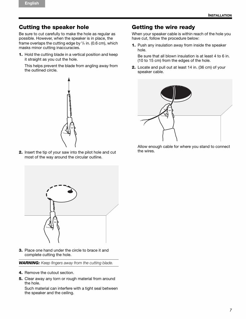
Cutting the speaker holeBe sure to cut carefully to make the hole as regular as possible. However, when the speaker is in place, the frame overlaps the cutting edge by 5/8 in. (0.6 cm), which masks minor cutting inaccuracies.
1. Hold the cutting blade in a vertical position and keep it straight as you cut the hole.
This helps prevent the blade from angling away from the outlined circle.
2. Insert the tip of your saw into the pilot hole and cut most of the way around the circular outline.
3. Place one hand under the circle to brace it and complete cutting the hole.
WARNING: Keep fingers away from the cutting blade.
4. Remove the cutout section.
5. Clear away any torn or rough material from around the hole. Such material can interfere with a tight seal between the speaker and the ceiling.
Getting the wire readyWhen your speaker cable is within reach of the hole you have cut, follow the procedure below:
1. Push any insulation away from inside the speaker hole.
Be sure that all blown insulation is at least 4 to 6 in. (10 to 15 cm) from the edges of the hole.
2. Locate and pull out at least 14 in. (36 cm) of your speaker cable.
Allow enough cable for where you stand to connect the wires.
7

INSTALLATION
EnglishTAB 6TAB 8 TAB 7 TAB 3TAB 5 TAB 2TAB 4
04_Installation.fm Page 8 Thursday, June 11, 2009 10:50 AM
Connecting the speakerAs you connect the wires, be careful to match the polarity of each wire to the proper terminal, as described below. An error here will adversely affect speaker performance.
1. Choose the one wire on the cable end that is marked with a colored collar or other indicator, (which distinguishes it as the positive (+) wire.
2. Notice the red circle on the exposed end of the positive (+) speaker terminal.
3. Compress both ends of the terminal and fully insert the bared tip of the positive wire into the terminal opening. Avoid inserting any insulated part of the wire.
4. Release pressure on the terminal to capture the wire.
5. Insert the other wire into the other terminal, marked with a black circle on the end to indicate it is negative (–).
CAUTION: Do not allow exposed wires to brush against each other. This could damage your speaker or your receiver/amplifier. Trim any excess wire and reinsert it as necessary.
Finishing the installationIt is important to have all of your equipment ready and within easy reach to complete this procedure.
Securing the speaker As you lift the speaker, keep the speaker cable above and out of the way to prevent pinching it.
You may notice a security flange, located on the upper edge of the speaker, for use where local building codes require it.
1. Use two hands to hold the edge of the speaker as you guide it into the ceiling hole.
CAUTION: Be sure not to press on the two small drivers seated on the face of the speaker.
CAUTION: Be careful not to damage or remove any of the foam gasket material along the edge of the speaker. This gasket is important to the operation of the speaker.
Positive (+) wire to positive
(red) terminal
Security flange
8
INSTALLATION
TAB 5TAB 4 TAB 6 TAB 8TAB 7English TAB 3TAB 2
04_Installation.fm Page 9 Thursday, June 11, 2009 10:50 AM
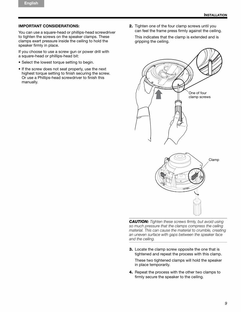
IMPORTANT CONSIDERATIONS:
You can use a square-head or phillips-head screwdriver to tighten the screws on the speaker clamps. These clamps exert pressure inside the ceiling to hold the speaker firmly in place.
If you choose to use a screw gun or power drill with a square-head or phillips-head bit:
• Select the lowest torque setting to begin.
• If the screw does not seat properly, use the next highest torque setting to finish securing the screw. Or use a Phillips-head screwdriver to finish this manually.
2. Tighten one of the four clamp screws until you can feel the frame press firmly against the ceiling.
This indicates that the clamp is extended and is gripping the ceiling.
CAUTION: Tighten these screws firmly, but avoid using so much pressure that the clamps compress the ceiling material. This can cause the material to crumble, creating an uneven surface with gaps between the speaker face and the ceiling.
3. Locate the clamp screw opposite the one that is tightened and repeat the process with this clamp.
These two tightened clamps will hold the speaker in place temporarily.
4. Repeat the process with the other two clamps to firmly secure the speaker to the ceiling.
One of four clamp screws
Clamp
9
INSTALLATION
EnglishTAB 6TAB 8 TAB 7 TAB 3TAB 5 TAB 2TAB 4
04_Installation.fm Page 10 Friday, June 12, 2009 11:34 AM
Testing each speaker With the speakers secured to your ceiling, you can make sure the speaker functions properly before you attach the grille.
CAUTION: Before you turn on your receiver/amplifier, be sure there is no unused speaker cable connected to it. An attached cable that is free at one end can cause a short and damage your receiver/amplifier.
1. Turn on the receiver/amplifier and play a piece of music that is familiar to you.
2. Make sure the sound is clear and free of static.
Static may indicate that the speaker cable is not connected properly. Refer to the “CAUTION:” on page 8.
Note: To remove the speaker and check the connections, loosen two of the screws that are opposite each other first. Use one hand to support the speaker as you loosen the third screw. Continue to support the speaker and carefully loosen the final screw.
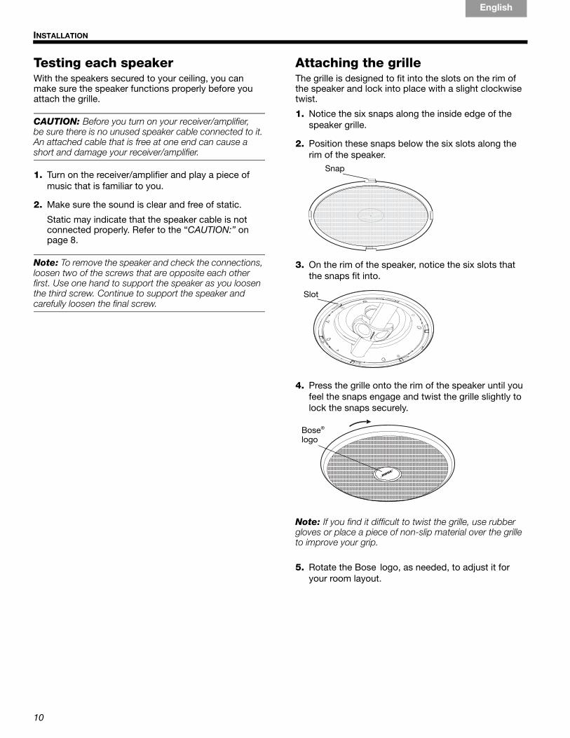
Attaching the grilleThe grille is designed to fit into the slots on the rim of the speaker and lock into place with a slight clockwise twist.
1. Notice the six snaps along the inside edge of the speaker grille.
2. Position these snaps below the six slots along the rim of the speaker.
3. On the rim of the speaker, notice the six slots that the snaps fit into.
4. Press the grille onto the rim of the speaker until you feel the snaps engage and twist the grille slightly to lock the snaps securely.
Note: If you find it difficult to twist the grille, use rubber gloves or place a piece of non-slip material over the grille to improve your grip.
5. Rotate the Bose logo, as needed, to adjust it for your room layout.
Snap
Slot
Bose® logo
10
TAB 5TAB 4 TAB 6 TAB 8TAB 7English TAB 3TAB 2
00_791_Speaker_IG.book Page 11 Wednesday, April 15, 2009 8:33 AM
REFERENCE
Painting the exterior parts You can paint the grille and frame of your Virtually Invisible® 791 speakers before you install them.
Be sure to use paint that is appropriate to the technique you choose, as described below. Painting is optional and Bose cannot be responsible for the quality of adhesion or finish of non-factory-applied paints.
WARNING: Follow all recommended safety procedures for the chemicals involved. This includes the proper use of eye protection, ventilation systems, respirators or filter masks, and fire safety equipment if flammable solvents are used.
Painting the grilleIt is important to prevent paint from clogging the grille perforations. This can adversely affect performance. You can use a dry brush or spray paint technique, as described here. However, do not use a paint roller.
• BE SURE to rotate the Bose® logo to the position you want before painting begins.
• Clean the grille to remove possible contaminants. Even fingerprints can prevent uniform coverage.
• Check to be sure the paint is distributed evenly and covers the grille thoroughly.
• Use a tissue paper or clean cloth to protect the painted grille when you remove the paint shield or attach the grille to the speaker.
Using a dry brush techniqueUnthinned latex paint is appropriate for this method. Be sure to put down enough paper to cover your work area and allow for repeatedly blotting the brush.
1. Dip the tip of a clean, dry brush in the paint.
2. Stroke across a piece of paper to reduce the amount of paint on the brush. When you can see individual bristle marks, the brush is ready to use on the grille.
3. Stroke lightly back and forth on the front of the grille, in a horizontal direction, until you need more paint.
Tip: If paint clogs any of the grille perforations, try angling your stroke or blow gently to unclog the paint.
4. When the entire grille is covered, turn the grille 180° and repaint it using back-and-forth strokes.
11
REFERENCE
EnglishTAB 6TAB 8 TAB 7 TAB 3TAB 5 TAB 2TAB 4
00_791_Speaker_IG.book Page 12 Wednesday, April 15, 2009 8:33 AM
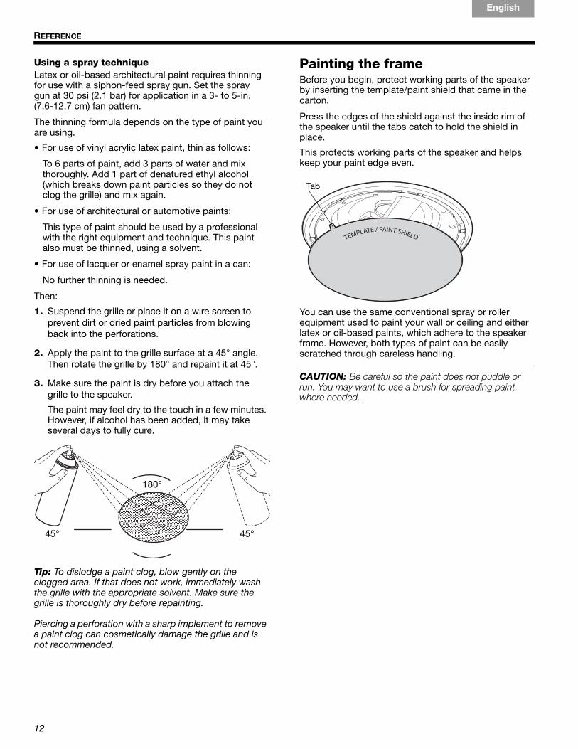
Using a spray techniqueLatex or oil-based architectural paint requires thinning for use with a siphon-feed spray gun. Set the spray gun at 30 psi (2.1 bar) for application in a 3- to 5-in. (7.6-12.7 cm) fan pattern.
The thinning formula depends on the type of paint you are using.
• For use of vinyl acrylic latex paint, thin as follows:
To 6 parts of paint, add 3 parts of water and mix thoroughly. Add 1 part of denatured ethyl alcohol (which breaks down paint particles so they do not clog the grille) and mix again.
• For use of architectural or automotive paints:
This type of paint should be used by a professional with the right equipment and technique. This paint also must be thinned, using a solvent.
• For use of lacquer or enamel spray paint in a can:
No further thinning is needed.
Then:
1. Suspend the grille or place it on a wire screen to prevent dirt or dried paint particles from blowing back into the perforations.
2. Apply the paint to the grille surface at a 45° angle. Then rotate the grille by 180° and repaint it at 45°.
3. Make sure the paint is dry before you attach the grille to the speaker.
The paint may feel dry to the touch in a few minutes. However, if alcohol has been added, it may take several days to fully cure.
Tip: To dislodge a paint clog, blow gently on the clogged area. If that does not work, immediately wash the grille with the appropriate solvent. Make sure the grille is thoroughly dry before repainting.
Piercing a perforation with a sharp implement to remove a paint clog can cosmetically damage the grille and is not recommended.
Painting the frameBefore you begin, protect working parts of the speaker by inserting the template/paint shield that came in the carton.
Press the edges of the shield against the inside rim of the speaker until the tabs catch to hold the shield in place.
This protects working parts of the speaker and helps keep your paint edge even.
You can use the same conventional spray or roller equipment used to paint your wall or ceiling and either latex or oil-based paints, which adhere to the speaker frame. However, both types of paint can be easily scratched through careless handling.
CAUTION: Be careful so the paint does not puddle or run. You may want to use a brush for spreading paint where needed.
45°
180°
45°
Tab
12
REFERENCE
TAB 5TAB 4 TAB 6 TAB 8TAB 7English TAB 3TAB 2
00_791_Speaker_IG.book Page 13 Wednesday, April 15, 2009 8:33 AM
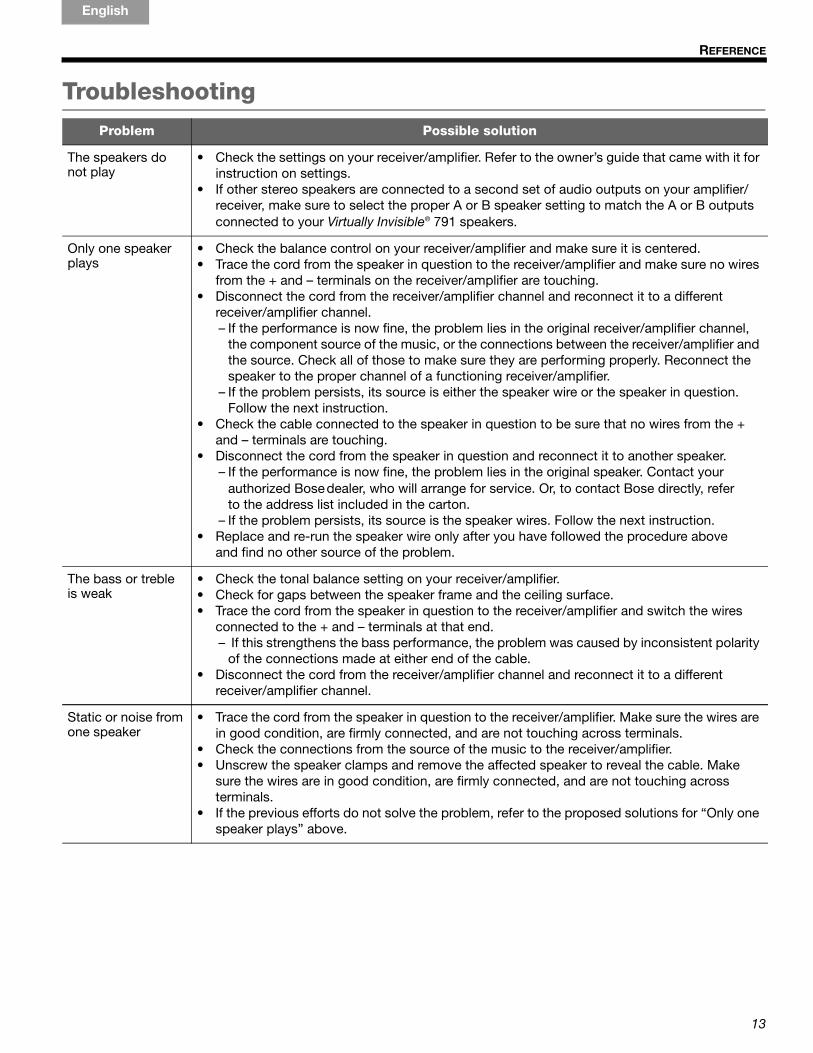
Troubleshooting
Problem Possible solution
The speakers do not play
• Check the settings on your receiver/amplifier. Refer to the owner’s guide that came with it for instruction on settings.
• If other stereo speakers are connected to a second set of audio outputs on your amplifier/ receiver, make sure to select the proper A or B speaker setting to match the A or B outputs connected to your Virtually Invisible® 791 speakers.
Only one speaker plays
• Check the balance control on your receiver/amplifier and make sure it is centered.• Trace the cord from the speaker in question to the receiver/amplifier and make sure no wires
from the + and – terminals on the receiver/amplifier are touching.• Disconnect the cord from the receiver/amplifier channel and reconnect it to a different
receiver/amplifier channel. – If the performance is now fine, the problem lies in the original receiver/amplifier channel,
the component source of the music, or the connections between the receiver/amplifier and the source. Check all of those to make sure they are performing properly. Reconnect the speaker to the proper channel of a functioning receiver/amplifier.
– If the problem persists, its source is either the speaker wire or the speaker in question. Follow the next instruction.
• Check the cable connected to the speaker in question to be sure that no wires from the + and – terminals are touching.
• Disconnect the cord from the speaker in question and reconnect it to another speaker.– If the performance is now fine, the problem lies in the original speaker. Contact your
authorized Bose dealer, who will arrange for service. Or, to contact Bose directly, refer to the address list included in the carton.
– If the problem persists, its source is the speaker wires. Follow the next instruction.• Replace and re-run the speaker wire only after you have followed the procedure above
and find no other source of the problem.
The bass or treble is weak
• Check the tonal balance setting on your receiver/amplifier.• Check for gaps between the speaker frame and the ceiling surface.• Trace the cord from the speaker in question to the receiver/amplifier and switch the wires
connected to the + and – terminals at that end.– If this strengthens the bass performance, the problem was caused by inconsistent polarity
of the connections made at either end of the cable.• Disconnect the cord from the receiver/amplifier channel and reconnect it to a different
receiver/amplifier channel.
Static or noise from one speaker
• Trace the cord from the speaker in question to the receiver/amplifier. Make sure the wires are in good condition, are firmly connected, and are not touching across terminals.
• Check the connections from the source of the music to the receiver/amplifier.• Unscrew the speaker clamps and remove the affected speaker to reveal the cable. Make
sure the wires are in good condition, are firmly connected, and are not touching across terminals.
• If the previous efforts do not solve the problem, refer to the proposed solutions for “Only one speaker plays” above.
13
REFERENCE
EnglishTAB 6TAB 8 TAB 7 TAB 3TAB 5 TAB 2TAB 4
05_Reference.fm Page 14 Thursday, April 23, 2009 10:10 AM
Customer serviceFor additional help in solving problems, contact your Bose dealer. Or, to contact Bose® Customer Service, refer to the address list included in the carton.
Limited warrantyYour Virtually Invisible® 791 speakers are covered by a limited transferable warranty. Details of the limited warranty are provided on the product registration card that is included in the carton. Please refer to the card for instructions on how to register. Failure to register will not affect your limited warranty rights.
What you must do to obtain Limited Warranty serviceReturn the product, with proof of purchase from an authorized Bose dealer, using the following procedures:
1. Contact the Bose organization in your country/region (visit Global.Bose.com for contact information in your country/region) for specific return and ship-ping instructions.
2. Label and ship the product, freight prepaid, to the address provided by the Bose organization in your country.
3. Place any necessary Return Authorization Number prominently on the outside of the carton. Cartons not bearing a Return Authorization Number, where required, will be refused.
AccessoriesFor unfinished construction, use the Bose Rough-in Kit.
The kit contains parts for two speakers and is designed for installation after the joists are in place and before wallboard is added. When installed, the kit reserves a place for each speaker and indicates where to make the speaker hole in the wallboard. The kit includes installa-tion instructions.
For further information or to order accessories, contact your Bose dealer. Or, to call Bose directly, refer to the address list included in the carton.
Technical information
Compatibility• Compatible with amplifiers or receivers rated
10-100W per channel/rated 4 to 8 ohms
• 50W IEC continuous power handling; rated 6 ohms
Driver complement• Two (2) 1" (2.54 cm) dome tweeters configured in
an array
• One (1) 7" (17.8 cm) high-excursion woofer
Material• Molded ABS engineering-grade polymer
• White frame and grille
Dimensions• Diameter of each speaker: 10 in. (25.4 cm)
• Depth, with grille on: 4.66 in. (12 cm)
• Ceiling hole diameter required: 85/8" (21.9 cm) diameter
• Finished surface required 10 in. (25.4 cm)
Weight• 4.73 lb (2.2 kg) each
14

Installation Guide
Installationsvejledning
Installationsanleitung
Guía de instalación
Asennusopas
Notice d’installation
Telepítési útmutató
Guida di installazione
Gebruikershandleiding
Podręcznik instalacji
Installationsanvisning
VIRTUALLY INVISIBLE® 791 SPEAKERS
©2009 Bose Corporation, The Mountain,Framingham, MA 01701-9168 USAAM321052 Rev.01
VIRTU
ALLY IN
VISIBLE
® 791 SPEAK
ERSCovers.fm Page 1 Friday, April 17, 2009 9:51 AM