numerical solutions of 2-d muwi-stage … · stage configurations. ... the space shuttle main...
TRANSCRIPT
NUMERICAL SOLUTIONS OF 2-D MUWI-STAGE ROTOR/STATOR UNSTEADY FLOW INTERACTIONS
R.-J. Yang and S. -J. Lin Rocketdyne Division, Rockwell International
Canoga Park, CA 91303
ABSTRAC
Rai's method [1,2] of single-stage rotor/stator flow interaction is extended to handle multi- stage configurations. In this study, a two-dimensional Navier-Stokes multi-zone approach has been used to investigate unsteady flow interactions within two multi-stage axial turbines. The governing equations are solved by an iterative, factored, implicit finite-difference, upwind algo- rithm. Numerical accuracy is checked by investigating the effect of time step size, the effect of subiteration in the Newton-Raphson technique and the effect of full viscous vs thin-layer approximation. Computed results are compared well with experimental data. Unsteady flow interactions, wake cutting and the associated evolution of vortical entities are discussed.
INTRODUCTION
In the past, a major portion of the computational analysis of turbomachinery was focused on steady-state solutions of isolated airfoils. In the case of rotor-stator configurations, there are aerodynamic interactions between stationary vanes (stator) and rotating blades (rotor). During the interactions, the flow is inherently unsteady because of potential effects, the cutting of wakes of upstream airfoils by downstream airfoils and vortex shedding by blunt trailing edges of the airfoils. The interaction effects are known to affect many aspects of turbomachinery performance including blade loading, stage efficiency, heat transfer, stall margin and noise generation. To understand the flow physics and thus to improve or aid designs, an accurate transient solution of the entire turbomachine would be very useful.
Rai [I] presented a one-stator lone-rotor interaction study. His calculation was performed on a system of patched and overlaid grids using the unsteady, thin-layer, Navier-Stokes equations in two-dimension. The airfoil geometries and flow conditions are the same as that in Ref.[3]. A good agreement between the calculation and the experimental result of Ref.131 was obtained in the case of time-averaged surface pressures on the stator and rotor. Unsteady fluctuating pressure amplitudes were also in reasonable agreement. Rai[2] extended his method to do multi- stator/multi-rotor calculation with a closer approximation to the experimental ahfoil geometries.
https://ntrs.nasa.gov/search.jsp?R=19910011757 2018-08-26T03:13:13+00:00Z
It was found the time-averaged pressures were nearIy identical to those of one-stator/one-rotor case. However, a significant improvement in unsteady fluctuating pressure amplitude and phase were obtained. Yang et al. 141 applied the method of Rai[l] to calculate the unsteady aero- dynamics of a one-stator/one-rotor configuration in the high pressure oxidizer turbopump of the space shuttle main engine. It described the vortex shedding wake cutting process and the associated unsteady convection of large scale vortical motion. It also found small time step size was required to resolve unsteady components in the flow field. Lin and Yang [5] applied the method of Rai [2] to simulate multi-stator/multi-rotor configuration in the high pressure fuel turbopump of the space shuttle main engine. It performed spatial and temporal accuracy studies to determine maximum time step and grid sizes within engineering accuracy and with minimum computational costs. The study showed that a factor of ten could be achieved in re- ducing computer time by judiciously enlarging time step size and reducing total number of grid points for the configurations considered. Griffin and McConnaughey [6] applied Rai's method [I] to compute unsteady heat transfer coefficients for stator/rotor configurations. Their computed results were compared well with experimental data.
The studies reported previously are for single-stage configurations. It is useful to extend Rai's method to have multi-stage capability because most turbomachines have multi-stage rotating components. Especially for the case if one is interested in those parts after first stage. The reason is that wake effects are important to characterize aerothermal behavior in the downstream stages. If one uses a single-stage approach, a time dependent wake condition at inlet has to be specified. Usually the wake condition is not known except provided by experiments. For a general approach, using a multi-stage method, the wake information is obtained from numerical solutions without invoking experimental data. This paper presents the extension of Rai's single- stage method to multi-stage case.
In extending Rai's method to multi-stage case, two technical aspects have to be addressed. First is the grid generation procedure and second is the flow solver. These issues will be de- scribed in the technical approach section. To validate our new coding~, a calculation using the United Technology Research Center one and half stages large scale rotating rig case is performed. Computed results in the form of time-averaged static pressure and unsteady fluctuating pressure amplitude on airfoil surfaces are presented and compared with experimental data. Numerical accuracy is investigated by a series of tests, namely, the effect of time step size, the effect of iteration in the Newton-Raphson technique and the effect of full viscous vs thin-layer approxi- mation. Finally, an application of the method to a six stages axial turbine in the space shuttle main engine low pressure oxidizer turbopump is demonstrated in the paper.
TECHNICAL APPROACN
Rai's single-stage ROTOR code [2] is adopted as a basis in the present study. The extension of the code to multi-stage case is described as follows:
(a) Grid Generation Procedure
There are two kinds of grid system often used in rotor/stator interaction study. One is single deforming grid system and another is multi-zone grid system. Single deforming grid system
suffers the grid skewness problem if the separation distance between vane and blade is small. Multi-zone grid system avoids the problem and has been demonstrated as an efficient system P lor - rotor/stator interaction problems[i,2]. The ROTOX code uses patched and overlaid grids
for single-stage case. Its extension to multi-stage case is straight forward. For each airfoil, there are two grid zones, namely, one inner '0-' grid, and one outer 'H-' grid. The inner '0-' grid encloses the airfoil surface and accurately resolves the leading and trailing edges. The '0-' grid is generated using an elliptic grid generator with the condition that the grid be orthogonal to the airfoil surface. The 'H-' grid is generated algebraically with the requirement that the metric coefficients be continuous across the periodic lines where periodic boundary conditions are imposed. A region of overlap exists between the '0-' and 'H-' grids. The vane and blade grid systems are separated by a common patched boundary to facilitate movements of the rotor grid system without any distortion of the grid lines. Information transfer between the different zones is affected by proper imposition of interface boundary conditions. Note that for a single-stage case, there is only one moving patched boundary. For a n-stage case, there are 211-1 moving patched boundaries.
(b) Flow Solver
The ROTOR code solves the unsteady, thin-layer Navier-Stokes equations in the '0-' grid zones, and the unsteady Euler equations in the 'H-' grid zones. The governing equations are cast in the strong conservation form. The numerical procedure used to solve the governing equations is an iterative, factored, implicit scheme. The governing equations are replaced by a fully implicit finite-difference approximation. Numerical fluxes are evaluated by the third-order accurate upwind-biased Osher scheme. The resulting system of nonlinear equations is solved by the Newton-Raphson iteration technique. To solve these difference equations at each iteration level, an approximate factorization method is used. This technique leads to system of coupled linear difference equations having narrow block-banded structures which can be solved efficiently by a LU decomposition method. Some subiterations may be used at each time step to reduce linearization and factorization errors.
The major effort of the present modification to the ROTOR code is to treat multiple moving patched boundary conditions correctly. During the interaction process, rotor airfoils move rela- tive to stator airfoils. Accurate method for information transfer between stationary and moving grids are necessary for multi-stage interaction problems. Rai[l] has developed a highly accurate method used for single-stage problems. Its extension to the multi-stage case is straight forward. In an independent study, Gundy-Burlet et al. [7] also presented a new code, STAGE-2, for a multi-stage compressor calculation.
(c) Boundary Condition
The use of multiple zones in simulating flows over rotor/stator configurations results in several computational boundaries, namely, inlet, exit, solid surface, periodic and zonal (overlap and patch) boundaries. The boundary conditions used at each of these boundaries are addressed briefly below.
For subsonic flow conditions, characteristic analysis requires three in-flow quantities and one out-flow quantity to be specified. Currently, the total pressure, the Riemann invariant corresponding to the right running characteristic, and the in-flwr mgle are specified at the inlet, and the Riemann invariant corresponding to the left running characteristic, is extrapolated from the interior to the inlet boundary. At the exit, the static pressure is specified, and three other variables are extrapolated from the interior. 'No-slip' and adiabatic wall boundary conditions are applied at the solid surfaces. It should be noted that in the case of the rotor airfoil 'no- slip' does not imply zero absolute velocity at the surface of the airfoil, but rather, zero relative velocity. The implementation of periodic boundary conditions is straight forward.
The present grid system (for instance see figure 2) consists the following two zonal boundaries: (1) The overlap boundary between the inner and outer zones for the rotor and stator. The
grid of outer zone exists concurrently with the grid of the inner zone in the inner zone area. Information transfer from the inner zone to the outer zone takes place within the inner zone.
(2) The patch boundary between the outer stator zone and the outer rotor zone. A one-grid overlap exists at this boundary, ie, the outer stator zone penetrate the outer rotor zone to the extent of one grid point (in the direction of the axis of the hub) and vice versa.
For the zonal boundaries (1) and (2), the boundary points are integrated by using the following relation:
where 6 is the vector of flow variables, the subscript z.b. refers to the points on a zonal boundary, the superscript p is the p-th Newton-Raphson iteration at a given time step. This is followed by an explicit, corrective interpolation procedure at the end of each iteration wherein the value of along the zonal boundary are obtained from interpolating the dependent variables of the neighboring grid in which the zonal boundaries lies. The zonal boundary can be treated in a manner such that the fluxes across them satisfy conservation condition. Since the current calculations are entirely subsonic and free of discontinuities, physically meaningful solutions can be obtained even with the use of nonconservative form of the equations. Therefore, the nonconservative overlap and patch boundary conditions used here can be expected to yield accurate solutions. Additional details regarding the implementation of zonal boundaries can be found in Ref.[l,8].
(d) Turbulence Model
Flows associated with rotor/stator configurations are unsteady in nature due to periodic interaction effects. In addition, the flow might have transition from laminar to full turbulence along airfoil surfaces. Near the trailing edges of airfoils, there exist large scale wake structures. Conventional turbulence models are developed to calculate steady mean flows. For unsteady tur- bulent flows, advanced turbulence models are required. As a starting point for the rotor/stator flow calculations, the Baldwin-Lomax model [lo] is used in the current studies. The kinematic viscosity is evaluated using the Sutherland's law.
COMPUTED RESULTS AND DISCUSSION
Two cases with different rotor/stator configurations and flow conditions are calculated by integrating the equations of motion and the boundary conditions described earlier. Case one is the United Technology Research Center (UTRC) 1.5 stages large scale rotating rig (LSRR). Case two is the 6 stages axial turbine in the space shuttle main engine (SSME) low pressure oxidizer turbopump (LPOTP) .
Case 1: UTRC 1.5 stages LSRR
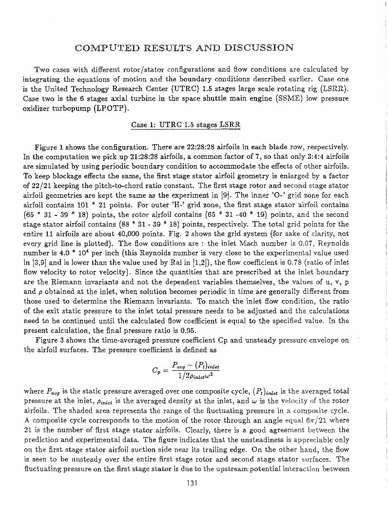
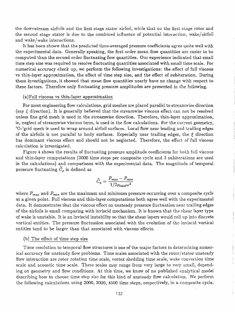
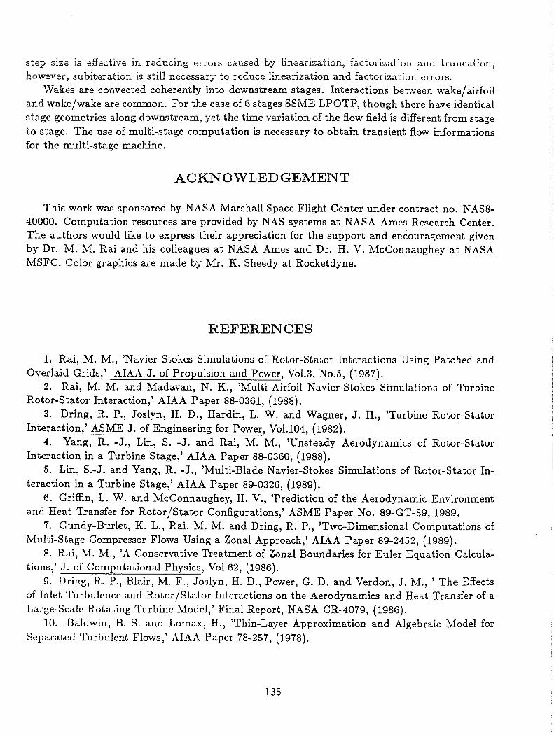
Figure 1 shows the configuration. There are 22:28:28 airfoils in each blade row, respectively. In the computation we pick up 21:28:28 airfoils, a common factor of 7, so that only 3:4:4 airfoils are simulated by using periodic boundary condition to accommodate the effects of other airfoils. To keep blockage effects the same, the first stage stator airfoil geometry is enlarged by a factor of 22/21 keeping the pitch-to-chord ratio constant. The first stage rotor and second stage stator airfoil geometries are kept the same as the experiment in [9]. The inner '0-' grid zone for each airfoil contains 101 * 21 points. For outer 'H-' grid zone, the first stage stator airfoil contains (65 * 31 - 39 * 18) points, the rotor airfoil contains (65 * 31 -40 * 19) points, and the second stage stator airfoil contains (88 * 31 - 39 * 18) points, respectively. The total grid points for the entire 11 airfoils are about 40,000 points. Fig. 2 shows the grid system (for sake of clarity, not every grid line is plotted). The flow conditions are : the inlet Mach number is 0.07, Reynolds number is 4.0 * lo4 per inch (this Reynolds number is very close to the experimental value used in [3,9] and is lower than the value used by Rai in [1,2]), the flow coefficient is 0.78 (ratio of inlet flow velocity to rotor velocity). Since the quantities that are prescribed at the inlet boundary are the Riemann invariants and not the dependent variables themselves, the values of u, v, p and p obtained at the inlet, when solution becomes periodic in time are generally different from those used to determine the Riemann invariants. To match the inlet flow condition, the ratio of the exit static pressure to the inlet total pressure needs to be adjusted and the calculations need to be continued until the calculated flow coefficient is equal to the specified value. In the present calculation, the final pressure ratio is 0.95.
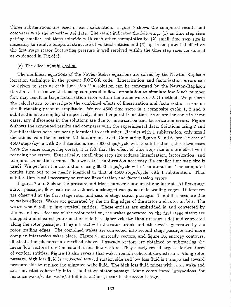
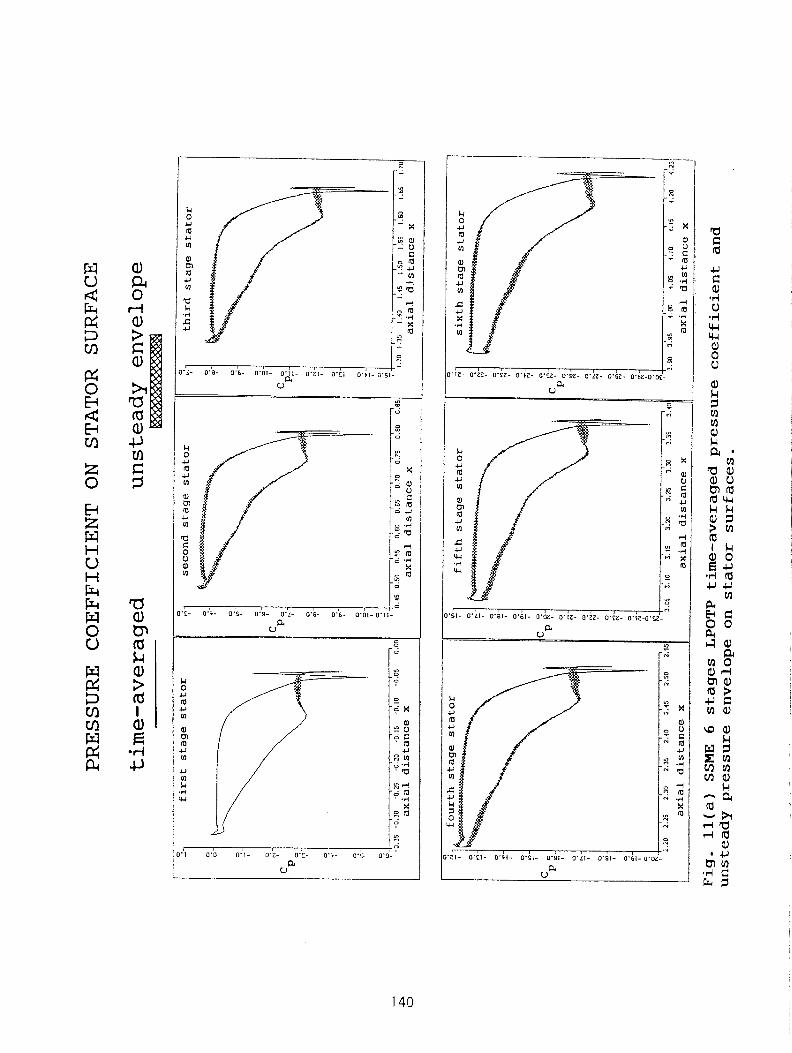
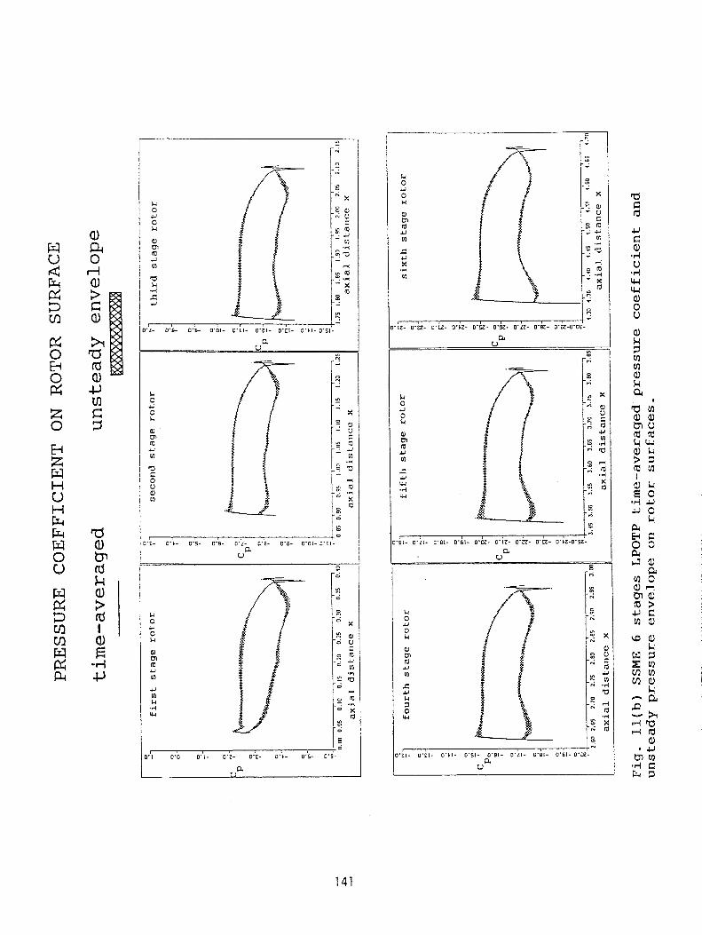
Figure 3 shows the time-averaged pressure coefficient Cp and unsteady pressure envelope on the airfoil surfaces. The pressure coefficient is defined as
where Pa,, is the static pressure averaged over one composite cycle, (Pt)idet is the averaged total pressure at the inlet, pinlet is the averaged density at the inlet, and w is the velocity of the rotor airfoils. The shaded area represents the range of the fluctuating pressure in a composite cycle. A composite cycle corresponds to the motion of the rotor through an angle equal 6 ~ / 2 1 where 21 is the number of first stage stator airfoils. Clearly, there is a good agreement between the prediction and experimental data. The figure indicates that the unsteadiness is appreciable only on the first stage stator airfoil suction side near its trailing edge. On the other hand, the flow is seen to be unsteady over the entire first stage rotor and second stage stator surfaces. The fluctuating pressure on the first stage stator is due to the upstream potential interaction between
131
the downstream airfoils and the first stage stator airfoil, while that on the first stage rotor and the second stage stator is due to the combined influence of potential interaction, wake/airfoil and wake/wake interactions.
It has been shown that the predicted time-averaged pressure coeficients agree quite well with the experimental data. Generally speaking, the first order mean flow quantities are easier to be computed than the second order fluctuating flow quantities. Our experience indicated that small time step size was required to resolve fluctuating quantities associated with small time scale. For numerical accuracy check up, we perform the following investigations: the effect of full viscous vs thin-layer approximation, the effect of time step size, and the effect of subiteration. During these investigations, it showed that mean flow quantities nearly have no change with respect to these factors. Therefore only fluctuating pressure amplitudes are presented in the following.
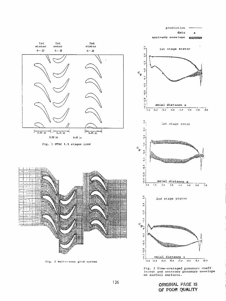
(a)Full viscous vs thin-layer approximation
For most engineering flow calculations, grid meshes are placed parallel to streamwise direction (say 6 direction). It is generally believed that the streamwise viscous effect can not be resolved unless fine grid mesh is used in the streamwise direction. Therefore, thin-layer approximation, ie, neglect of streamwise viscous term, is used in the flow calculations. For the current geometry, '0-'grid mesh is used to wrap around airfoil surfaces. Local flow near leading and trailing edges of the airfoils is not parallel to body surfaces. Especially near trailing edges, the 6 direction has dominant viscous effect and should not be neglected. Therefore, the effect of full viscous calculation is investigated.
Figure 4 shows the results of fluctuating pressure amplitude coefficients for both full viscous and thin-layer computations (3000 time steps per composite cycle and 3 subiterations are used in the calculations) and comparisons with the experimental data. The magnitude of temporal pressure fluctuating Cp is defined as
where P,,, and Pmin are the maximum and minimum pressure occurring over a composite cycle at a given point. Full viscous and thin-layer computations both agree well with the experimental data. It demonstrates that the viscous effect on unsteady pressure fluctuation near trailing edges of the airfoils is small comparing with inviscid mechanism. It is known that the shear layer type of wake is unstable. It is an inviscid instability so that the shear layers would roll up into discrete vortical entities. The pressure fluctuation associated with the evolution of the inviscid vortical entities tend to be larger than that associated with viscous effects.
(b) The effect of time step size
Time resolution to temporal flow structures is one of the major factors in determining numer- ical accuracy for unsteady flow problems. Time scales associated with the rotor/stator unsteady flow interaction are rotor rotation time scale, vortex shedding time scale, wake convection time scale and acoustic time scale. These scales may range from very large to very small, depend- ing on geometry and flow conditions. At this time, we know of no published analytical model describing how to choose time step size for this kind of unsteady flow calculation. We perform the following calculations using 2000, 3000, 4500 time steps, respectively, in a composite cycle.
Three subiterations are used in each calculation. Figure 5 shows the computed results and compares with the experimental data. The result indicates the following: (1) as time step sizes getting smaller, solutions coincide with each other mymptotically, (2) small time step size is necessary to resolve temporal structure of vortical entities and (3) upstream potential effect on the first stage stator fluctuating pressure is well resolved within the time step sizes considered as evidenced in Fig.S(a).
(c) The effect of subiteration
The nonlinear equations of the Navier-Stokes equations are solved by the Newton-Raphson iteration technique in the present ROTOR code. Linearization and factorization errors can be driven to zero at each time step if a solution can be converged by the Newton-Raphson iteration. It is known that using compressible flow formulation to simulate low Mach number flow may result in large factorization error within the frame work of AD1 method. We perform the calculations to investigate the combined effects of linearization and factorization errors on the fluctuating pressure amplitude. We use 4500 time steps in a composite cycle; 1, 2 and 3 subiterations are employed respectively. Since temporal truncation errors are the same in these cases, any differences in the solutions are due to linearization and factorization errors. Figure 6 shows the computed results and compares with the experimental data. Solutions using 2 and 3 subiterations both are nearly identical to each other. Results with 1 subiteration, only small deviations from the experimental data are observed. Comparing figures 5 and 6 (see the case of 4500 steps/cycle with 2 subiterations and 3000 steps/cycle with 3 subiterations, these two cases have the same computing costs), it is felt that the effect of time step size is more effective in reducing the errors. Heuristically, small time step size reduces linearization, factorization, and temporal truncation errors. Then we ask: is subiteration necessary if a smaller time step size is used? We perform the calculations using 6000 steps/cycle with 1 subiteration. The computed results turn out to be nearly identical to that of 4500 steps/cycle with 1 subiteration. Thus subiteration is still necessary to reduce linearization and factorization errors.
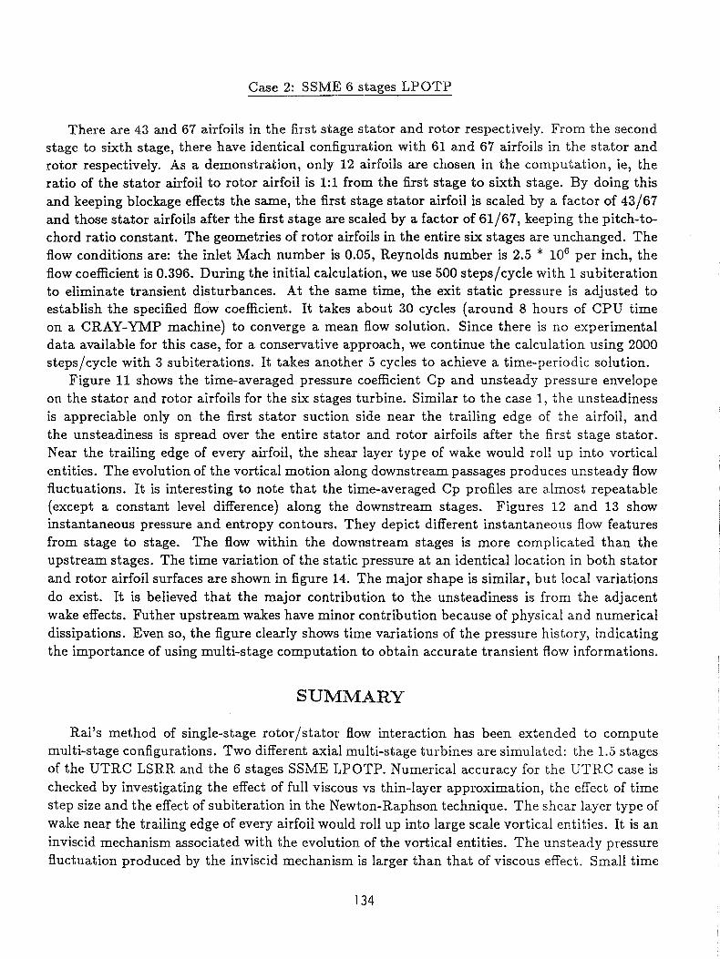
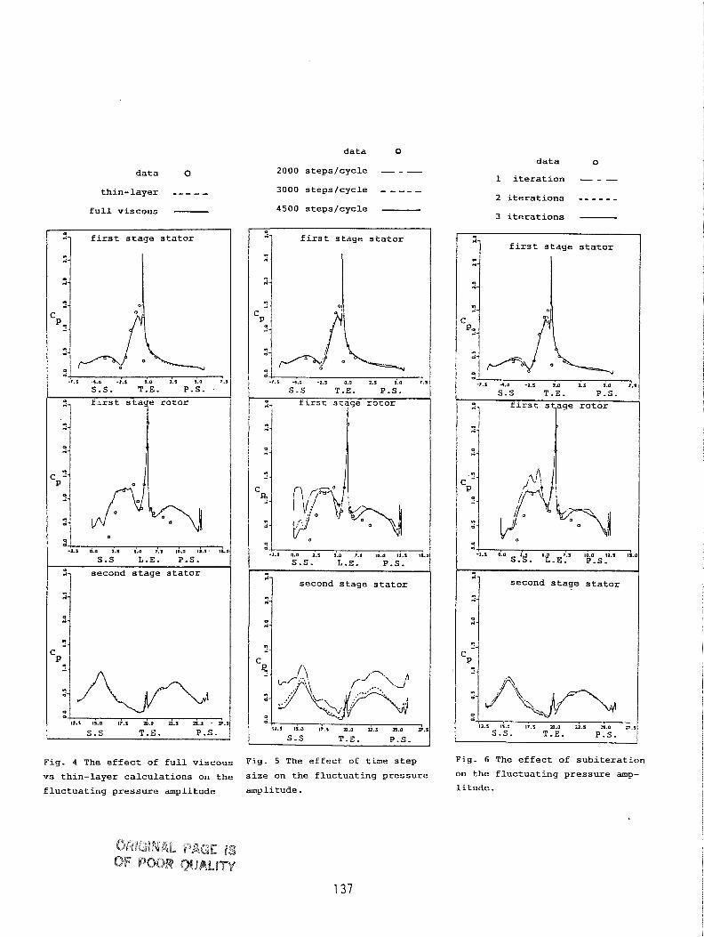
Figures 7 and 8 show the pressure and Mach number contours at one instant. At first stage stator passages, flow features are almost unchanged except near its trailing edges. Differences are observed at the first stage rotor and second stage stator passages. The differences are due to wakes effects. Wakes are generated by the trailing edges of the stator and rotor airfoils. The wakes would roll up into vortical entities. These entities are embedded in and convected by the mean flow. Because of the rotor rotation, the wakes generated by the first stage stator are chopped and sheared (rotor suction side has higher velocity than pressure side) and convected along the rotor passages. They interact with the rotor airfoils and other wakes generated by the rotor trailing edges. The combined wakes are convected into second stage passages and more complex interaction takes place. Figure 9, unsteady vectors, and figure 10, entropy contours, illustrate the phenomena described above. Unsteady vectors are obtained by subtracting the mean flow vectors from the instantaneous flow vectors. They clearly reveal large scale structures of vortical entities. Figure 10 also reveals that wakes remain coherent downstream. Along rotor passage, high loss fluid is convected toward suction side and low loss fluid is transported toward pressure side to replace the migrated wake fluid. The high loss fluid mixes with rotor wake and are convected coherently into second stage stator passage. Many complicated interactions, for instance wake/wake, wakelairfoil interactions, occur in the second stage.
Case 2: SSME 6 stages LPOTP
There are 43 and 67 airfoils in the first stage stator and rotor respectively. From the second stage to sixth stage, there have identical configuration with 61 and 67 airfoils in the stator and rotor respectively. As a demonstration, only 12 airfoils are chosen in the computation, ie, the ratio of the stator airfoil to rotor airfoil is 1:l from the first stage to sixth stage. By doing this and keeping blockage effects the same, the first stage stator airfoil is scaled by a factor of 43/67 and those stator airfoils after the first stage are scaled by a factor of 61/67, keeping the pitch-to- chord ratio constant. The geometries of rotor airfoils in the entire six stages are unchanged. The flow conditions are: the inlet Mach number is 0.05, Reynolds number is 2.5 * lo6 per inch, the flow coefficient is 0.396. During the initial calculation, we use 500 steps/cycle with I subiteration to eliminate transient disturbances. At the same time, the exit static pressure is adjusted to establish the specified flow coefficient. It takes about 30 cycles (around 8 hours of CPU time on a CRAY-YMP machine) to converge a mean flow solution. Since there is no experimental data available for this case, for a conservative approach, we continue the calculation using 2000 steps/cycle with 3 subiterations. It takes another 5 cycles to achieve a time-periodic solution.
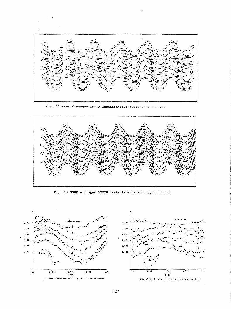
Figure 11 shows the time-averaged pressure coefficient Cp and unsteady pressure envelope on the stator and rotor airfoils for the six stages turbine. Similar to the case 1, the unsteadiness is appreciable only on the first stator suction side near the trailing edge of the airfoil, and the unsteadiness is spread over the entire stator and rotor airfoils after the first stage stator. Near the trailing edge of every airfoil, the shear layer type of wake would roll up into vortical entities. The evolution of the vortical motion along downstream passages produces unsteady flow fluctuations. It is interesting to note that the time-averaged Cp profiles are almost repeatable (except a constant level difference) along the downstream stages. Figures 12 and 13 show instantaneous pressure and entropy contours. They depict different instantaneous flow features from stage to stage. The flow within the downstream stages is more complicated than the upstream stages. The time variation of the static pressure at an identical location in both stator and rotor airfoil surfaces are shown in figure 14. The major shape is similar, but local variations do exist. It is believed that the major contribution to the unsteadiness is from the adjacent wake effects. Futher upstream wakes have minor contribution because of physical and numerical dissipations. Even so, the figure clearly shows time variations of the pressure history, indicating the importance of using multi-stage computation to obtain accurate transient flow informations.
SUMMARY
Rai's method of single-stage rotor/stator flow interaction has been extended to compute multi-stage configurations. Two different axial multi-stage turbines are simulated: the 1.5 stages of the UTRC LSRR and the 6 stages SSME LPOTP. Numerical accuracy for the UTRC case is checked by investigating the effect of full viscous vs thin-layer approximation, the effect of time step size and the effect of subiteration in the Newton-Raphson technique. The shear layer type of wake near the trailing edge of every airfoil would roll up into large scale vortical entities. It is an inviscid mechanism associated with the evolution of the vortical entities. The unsteady pressure fluctuation produced by the inviscid mechanism is larger than that of viscous effect. Small time
step size is effective in reducing errors caused by linearization, factorization and truncation, however, subiteration is still necessary to reduce linearization and factorization errors.
Wakes are convected coherently into downstream stages. Interactions between wake/airfoil and wakelwake are co on. For the case of 6 stages SSME LPOTP, though there have identical stage geometries along dowmtream, yet the time variation of the Bow field is different from stage to stage. The use of multi-stage computation is necessary to obtain transient flow informations for the multi-stage machine.
ACKNOWLEDGEMENT
This work was sponsored by NASA Marshall Space Flight Center under contract no. NAS8- 40000. Computation resources are provided by NAS systems at NASA Ames Research Center. The authors would like to express their appreciation for the support and encouragement given by Dr. M. M. Rai and his colleagues at NASA Ames and Dr. H. V. McConnaughey at NASA MSFC. Color graphics are made by Mr. K. Sheedy at Rocketdyne.
REFERENCES
1. Rai, M. M., 'Navier-Stokes Simulations of Rotor-Stator Interactions Using Patched and Overlaid Grids,' AIAA J. of Propulsion and Power, Vo1.3, No.5, (1987).
2. Rai, M. M. and Madavan, N. K., 'Multi-Airfoil Navier-Stokes Simulations of Turbine Rotor-Stator Interaction,' AIAA Paper 88-0361, (1988).
3. Dring, R. P., Joslyn, H. D., Hardin, L. W. and Wagner, J. H., 'Turbine Rotor-Stator Interaction,' ASME J. of Engineering for Power, Vo1.104, (1982).
4. Yang, R. -J., Lin, S. -J. and Rai, M. M., 'Unsteady Aerodynamics of Rotor-Stator Interaction in a Turbine Stage,' AIAA Paper 88-0360, (1988).
5. Lin, S.-J. and Yang, R. -J., 'Multi-Blade Navier-Stokes Simulations of Rotor-Stator In- teraction in a Turbine Stage,' AIAA Paper 89-0326, (1989).
6. Griffin, L. W. and McConnaughey, H. V., 'Prediction of the Aerodynamic Environment and Heat Transfer for Rotor/Stator Configurations,' ASME Paper No. 89-GT-89, 1989.
7. Gundy-Burlet, K. L., Rai, M. M. and Dring, R. P., 'Two-Dimensional Computations of Multi-Stage Compressor Flows Using a Zonal Approach,' AIAA Paper 89-2452, (1989).
8. Rai, M. M., 'A Conservative Treatment of Zonal Boundaries for Euler Equation Calcula- tions,' J . of Computational Physics, Vo1.62, (1986).
9. Dring, R. P., Blair, M. F., Joslyn, H. D., Power, G. D. and Verdon, J. M., ' The Effects of Inlet Turbulence and Rotor/Stator Interactions on the Aerodynamics and Heat Transfer of a Large-Scale Rotating Turbine Model,' Final Report, NASA CR-4079, (1986).
10. Baldwin, B. S. and Lomax, H., 'Thin-Layer Approximation and Algebraic Model for Separated Turbulent Flows,' AIAA Paper 78-257, (1978).
p r e d i c t i o n --------
1 s t 1 s t s t a t o r rotor
N = 2 2 N - i B
2nd s t a t o r
N = a3
a x i a l d i s t a n c e x
-7.0 -6.0 -5.0 4 . 0 1 . 0 -2.0 -1.0 0.0
F i g . 1 UTRC 1 . 5 s tages LSRR
F i g . 2 Multi-zone grid system
d a t a r
unsteady e n v e l o p e
'1 1 s t s t a g e S t a t o r
1 s t s t a g e r o t o r
c,
2nd s t a g e s t a t o r : 1
9 '- a x i a l d i s t a n c e x - 1
13.0 14.0 15.0 16.0 17.0 10.0 19.0 20.0
F i g . 3 Time-averaged pressure c o e f f - l c l e n t and unsteady p r e s s u r e e n v e l o p e on a i r f o i l s u r f a c e s .
data 0
thin-layer - -, - - full viscous -
S.S L.E. P.S.
second stage stator
S.S T.E. P.S. I
data 0
ZOO0 steps/cycle - - - 3000 steps/cycle - - -- - 4500 steps/cycle -
data o
1 iteration - - - 2 iterations - - - - - - 3 iterations -
- f - " n-
1-
m
Fig. 4 The effect of full viscous Fig. 5 The effect of time step Fig. 6 The effect of subiteration
vs thin-layer calculations on the size on the fluctuating pressure On the Pressure amp-
fluctuating pressure amplitude amplitude. litude.
first stage stator - n-
first stage stator
-7.5 4.0 2.5 5.0 1.1 3.0
m -- C P - " 0-
I, , .
C
-r .s 4.0 -1.1 0.0 i.a i.0 ;.s
S .S T.E. P.S.
i
S '2.1 L O 2.1 5.0 7.1 18.0 12.1 11.0
S.S. L.E. P.S.
..- " '4-
- n-
m - C
-2.s 0.OS~l$. s.i-E;l 10.0 l2.S 1i.n P.S.
second stage stator - I- " r i -
1-
m -- C P * -
11.5 1s.0 17.5 a.0 . I 11.0 $.I
S-S T.E. P.S.
second stage stator
S.S. T.E. P.S.
Figure 7: UTRC LSRR instantaneous pressure contours.
Figure 8: UTRC LSRR instantaneous Mach number contours.
138 ORlGlNAL PAGE IS OF POOR Q U A W
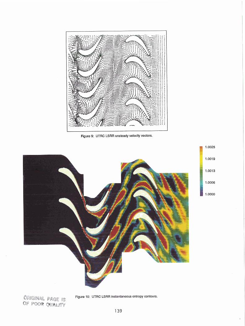
Figure 9: UTRC LSRR unsteady velacity vectors.
ORIGINAL PAGE 1s Figure 10: UTRC LSRR instantaneous entropy contours.
OF POOR QUA^^
- ,. - "? -
LC 0 0 'D
U . .. .
0 X LC .? al 0) - u m (0
c -9 'J
u ,U V)
.A C - .p Q u X d .r( 'n
O m - . .d - X ," .- ::
0 . k - o.k- o - u - o.iz- o - k 0 . i - 0 . k - a&- o.k-o.oL ..
a U
"7
I
F i g . 12 SSHE 6 s t a g e s LPOTP ins tantaneous p r e s s u r e c o n t o u r s .
F i g . 13 SSNE 6 s t a g e s LPOTP ins tantaneous entropy contours
s t a g e no.
I I
0 . 0 . 2 5 0 . 5 0 0 . 7 5 1 . 0 11 .I25 11 .I50 11 .,15 I!O TIHE 'ClHR
Fig. 14(a) Pressure h l s t o r g on s t a t o r surface F i g . 14tb) Pcesauro h i s t o r y on ro tor surface