numerical simulation of sliding wear for self-lubricating spherical plain bearings
TRANSCRIPT

7/24/2019 Numerical Simulation of Sliding Wear for Self-lubricating Spherical Plain Bearings
http://slidepdf.com/reader/full/numerical-simulation-of-sliding-wear-for-self-lubricating-spherical-plain-bearings 1/5
Numerical Simulation of Sliding Wear for
Self-lubricating Spherical Plain Bearings
Xuejin Shen1,*, Yunfei Liu1, Lei Cao1, Xiaoyang Chen1
1Department of Mechanical Automation, Shanghai University, Shanghai 200072, China.
Manuscript received February 10, 2012; in revised form April 18, 2012
Based on the thermo-mechanical nite element analysis method, a thermal wear simulation program was designed for the wear
properties analysis of spherical plain bearing with self-lubricating fabric liners. In the program, the classical Archard wear model was
applied to analyze the dynamical wear process of the bearing, and Abaqus scripting interface was used to simulate the progressive
accumulation of wear between contact surfaces. The position of maximum wear depth occurs at the central contact region and this
is in close agreement with test results. The relative error of the maximum wear depth between the FEA prediction and experimental
results is a little more than 10%. It is shown that the complex nonlinear wear process can be simulated with a series of discrete quasi
static models and the wear simulation program could be used to analyze the practical mechanical and tribological properties of the
spherical plain bearings.
KEY WORDS: Spherical plain bearing; Finite element method (FEM); Wear simulation; Thermal analysis
© 2012 Brazilian Metallurgical, Materials and Mining Association. Published by Elsevier Editora Ltda. All rights reserved.
1. Introduction
The diversity and complexity of wear phenomenon make it
dif cult to accurately predict wear life of mechanical parts.
The most condent knowledge about the friction pair tribo-
logical behaviour can be achieved by making a great number
of wear experiments. However, experimental exploration isnot only costly, but also not satisfactory when it comes to
practical problems of uneven load distributions as well as
changeable loads, such as wear life span of spherical plain
bearing with woven fabric liner.
With the rapid development of computer technology and
tribology in the past 20 years, “calculation tribology” has
become a branch of tribology[1,2] and has demonstrated its
strong vitality. FEM is widely used to simulate wear progress
of mechanical parts. Hegadekatte et al.[3–6] calculated wear
of the micro-mechanical devices based on nite element
simulations. Experimental results were in good accordance
with the simulation results. Kim et al.[7] simulated a block-
on-ring experiment and achieved good results. FEM was also
used to simulate fretting wear as well as the evolution offretting variables with the number of wear cycles in a cylin-
der on at conguration both made of Super CMV, a hardened
steel alloy[8].
The spherical plain bearings with self-lubricating can
achieve self-lubrication and long life due to their own struc-
tural characteristics, so they have been widely used in aero-
space, tank cannon gun system etc. Fig. 1 gives the structure
schematic diagram of these type bearings. It is composed of
an inner ring with a spherical outside surface and an outer
ring which has an inner sphere. Woven fabric liner is pasted*Corresponding author.
E-mail address: [email protected] (X. Shen)
ORIGINAL ARTICLE
© 2012 Brazilian Metallurgical, Materials and Mining Association. Published by Elsevier Editora Ltda. All rights reserved.
Journal of Materials Research and Technology
www . jm r t . c om .b r

7/24/2019 Numerical Simulation of Sliding Wear for Self-lubricating Spherical Plain Bearings
http://slidepdf.com/reader/full/numerical-simulation-of-sliding-wear-for-self-lubricating-spherical-plain-bearings 2/5
9Numerical Simulation of Sliding Wear for Self-lubricating Spherical Plain Bearings
3. Finite Element Modeling and Simulation
3.1. Finite Element Modeling
The spherical plain bearing shown in Fig. 1 was taken asan example of wear simulation. The outer ring and inner
ring of the bearing were made of aluminum alloy and the
self-lubricating liner was composed of woven fabric liner.
For simulating the experimental conditions of the bearing
system (Fig. 2), a test ring and shaft were also implemented
in the modeling, both of which were of rigid body. Since
analytical method was not available to analyze spherical
plain bearing problems, nite element analysis code Abaqus
was used to solve the non-linear contact problem. The
strength of nite element analysis in making wear predic-
tions is its ability to accurately consider both the variation
of the contact pressure and the progressive change of the
surface geometry caused by material removal in complexthree-dimensional components. Shen et al.[10] showed that
the maximum contact pressure between inner ring and
outer ring occurred on the axial cross-section, which was
the intersection plane between XOY plane and the bearing
system (Fig. 3). Therefore, the maximum wear depth would
occur in the same section in terms of Archard’s wear model.
In order to simplify calculations, two dimensional nite ele-
ment wear simulation model of the spherical plain bearing
was established (Fig. 3).
on the inner surface of the outer ring. The main failure form
of these type bearings is the wear of the woven fabric liner.
Based on the thermo-mechanical nite element analysis,
a numerical simulation forecasting method was proposed tosolve the sliding wear problem of the spherical plain bearings
with self-lubricating fabric liner in this paper.
2. Archard Wear Model
The wear process can be treated as a dynamic process de-
pending on many parameters and the prediction of that pro-
cess as an initial value problem. The most frequently used
model is based on the Archard’s wear law. Archard’s equation
for sliding wear is normally expressed as[9]
where V is the wear volume, s is the sliding distance, F N is
the normal load, H is the hardness of the worn surface, and
k is the dimensionless wear rate. In order to simulate the
evolution of the contact surface proles with wear cycles,
it is necessary to determine the wear depth at each contact
node of the nite element model. Therefore, for an inni-
tesimally small apparent contact area, A, the increment
of wear depth, dhw , associated with an increment of sliding
distance, ds, is determined. This can be obtained by applying
(1) locally to the area, A, and for the increment of sliding
distance, ds:
The F N / A term is the local contact pressure, p, while
dV / A is the required increment of local wear depth, dhw .
The following equation is thus obtained for the prediction of
the increment of local wear depth:
where k/H is replaced by kD, the dimensional wear rate.
Thus, the total wear depth hw of every element between the
contact surfaces could be formulated as
(1)
H
F k
s
V N
(2) A H
F k Ads
dV N
(3) pk ds
dh D
w
(4) ds pk h D
w
Fig. 1 Schematic of spherical plain bearing with self-lubricating
Fig. 2 Schematic of bearing test system
Fig. 3 Axial cross-section model of spherical plain bearing
RPX

7/24/2019 Numerical Simulation of Sliding Wear for Self-lubricating Spherical Plain Bearings
http://slidepdf.com/reader/full/numerical-simulation-of-sliding-wear-for-self-lubricating-spherical-plain-bearings 3/5
10 Shen et al.
3.2. Wear Simulation Routine
The ow chart of the nite element wear simulation pro-
cedure consists of a series of thermo-mechanical coupled
solution steps (Fig. 4). The Abaqus scripting interface was
introduced to carry out the wear simulation program.
The initial parameters given dened the model geom-
etry, loads, constraints, and wear model parameters along
with the element and material data. The heat ux wasobtained from the three-dimensional thermo-mechanical
analysis model of the bearing system[10]. Special subroutines
were developed for every conguration to generate the FE
model and dene the loads and constraints automatically.
Simulation of wear began with the solution of the general
contact problem using Abaqus. Then, Archard’s wear model
was implemented to calculate linear wear. According to the
wear depth, the FE model was updated. If oscillating cy-
cles, n nmax
, (predetermined maximum oscillating cycles)
or the node temperature, T , exceeds the maximum allow-
able temperature, T up-limit
, the cycle of calculation would be
stopped, otherwise it would go to the next iteration process
until the above two conditions were satised.
3.3. Re-Meshing Technology and Proper WearStep
To analyze dynamical wear process of the bearing, the entire
wear distance was divided into many wear steps. At the same
time, a proper re-meshing technology and selected wear
step should be used to increase the calculation ef ciency
and precision.
In order to simulate wear of the contact surface, the
nodes coordinate position must be changed, because the cal-
culating mesh on the surface is worn out. Whereas, changing
positions of boundary nodes may yield inaccurate sensitiv-
ity results or a distorted nite element mesh, and thus fail
in achieving an optimal solution. Therefore, it is necessaryto re-mesh the model after each cycle. Boundary displace-
ment method (BDM) of the design sensitivity analysis (DSA) is
widely employed to update the nite element mesh for FEA.
Before using BDM, displacements of each element node must
be calculated. Then, the displacements are used to update
the nite element model.
The integration wear step is another parameter re-
garding the calculation ef ciency and the reliability of
simulation results. The entire wear distance was divided
into nite wear steps. Too long wear step causes erratic
results and possibly the un-convergence of FEA procedure.
Too short interval takes too much computing time. Thus,
adopting appropriate wear step is necessary to improvethe computational ef ciency. As for spherical plain bear-
ing, wear depth of the central region increased quickly
at the beginning because of the higher contact pressure.
As wear distance went on, the contact pressure on the
border region of the contact surface increased and that of
the middle region decreased. At last, oscillating wear
of the bearing achieved a steady state, called linear
wear state. In order to simulate the rapid wear depth
change at the beginning, a varying wear step was em-
ployed for the wear process. As shown in Table 1, in the
early steps, a smaller wear step was implemented while a
greater one was used in the subsequent steps. Therefore,
176 times iteration calculations would be implement for
the wear simulation of 25,000 oscillation cycles.
4. Wear Simulation Results and Discussions
The spherical plain bearing used in this study was alu-
minum alloy bearing lubricated with woven fabric com-
posite liner. The wear occurs on the contacting surfaces
between inner ring and outer ring. In the swing process
of the bearing, the aluminum alloy mass loss on the out-
er surface of the inner ring is very small compared with
the woven fabric liner pasted on the inner surface of the
outer ring. That is why the wear takes place mainly on
the fabric liner of the inner surface of the outer ring. So,
only the mass loss of the self-lubricating liner is consideredin the wear simulation, while ignoring the material loss of
Fig. 4 Wear simulation ow chart of spherical plain bearing
Table 1 Adaptive wear step
Oscillating Cycles, n Wear Step
n < 200 2 cycles
200 n < 500 50 cycles
500 n < 5,000 100 cycles
5,000 n < 10,000 500 cycles
n 10,000 1,000 cycles
nnmax or
T T up-limit
7/24/2019 Numerical Simulation of Sliding Wear for Self-lubricating Spherical Plain Bearings
http://slidepdf.com/reader/full/numerical-simulation-of-sliding-wear-for-self-lubricating-spherical-plain-bearings 4/5
11Numerical Simulation of Sliding Wear for Self-lubricating Spherical Plain Bearings
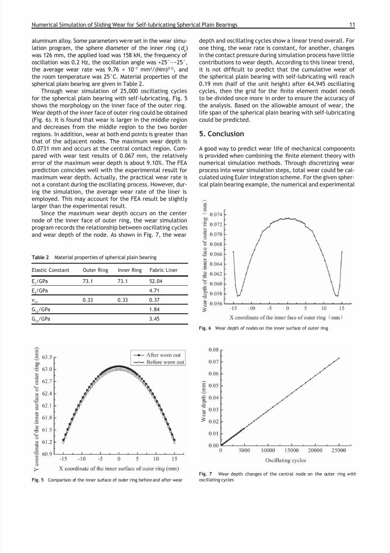
aluminum alloy. Some parameters were set in the wear simu-
lation program, the sphere diameter of the inner ring (d k)
was 126 mm, the applied load was 158 kN, the frequency of
oscillation was 0.2 Hz, the oscillation angle was +25°~25°,
the average wear rate was 9.76 × 107 mm3/(Nm)[11], and
the room temperature was 25°C. Material properties of the
spherical plain bearing are given in Table 2.
Through wear simulation of 25,000 oscillating cycles
for the spherical plain bearing with self-lubricating, Fig. 5shows the morphology on the inner face of the outer ring.
Wear depth of the inner face of outer ring could be obtained
(Fig. 6). It is found that wear is larger in the middle region
and decreases from the middle region to the two border
regions. In addition, wear at both end points is greater than
that of the adjacent nodes. The maximum wear depth is
0.0731 mm and occurs at the central contact region. Com-
pared with wear test results of 0.067 mm, the relatively
error of the maximum wear depth is about 9.10%. The FEA
prediction coincides well with the experimental result for
maximum wear depth. Actually, the practical wear rate is
not a constant during the oscillating process. However, dur-
ing the simulation, the average wear rate of the liner isemployed. This may account for the FEA result be slightly
larger than the experimental result.
Since the maximum wear depth occurs on the center
node of the inner face of outer ring, the wear simulation
program records the relationship between oscillating cycles
and wear depth of the node. As shown in Fig. 7, the wear
depth and oscillating cycles show a linear trend overall. For
one thing, the wear rate is constant, for another, changes
in the contact pressure during simulation process have little
contributions to wear depth. According to this linear trend,
it is not dif cult to predict that the cumulative wear of
the spherical plain bearing with self-lubricating will reach
0.19 mm (half of the unit height) after 64,945 oscillating
cycles, then the grid for the nite element model needs
to be divided once more in order to ensure the accuracy ofthe analysis. Based on the allowable amount of wear, the
life span of the spherical plain bearing with self-lubricating
could be predicted.
5. Conclusion
A good way to predict wear life of mechanical components
is provided when combining the nite element theory with
numerical simulation methods. Through discretizing wear
process into wear simulation steps, total wear could be cal-
culated using Euler integration scheme. For the given spher-
ical plain bearing example, the numerical and experimental
Table 2 Material properties of spherical plain bearing
Elastic Constant Outer Ring Inner Ring Fabric Liner
E1/GPa 73.1 73.1 52.04
E2/GPa 4.71
12
0.33 0.33 0.37
G12
/GPa 1.84
G23
/GPa 3.45
Fig. 5 Comparison of the inner surface of outer ring before and after wear
Fig. 6 Wear depth of nodes on the inner surface of outer ring
Fig. 7 Wear depth changes of the central node on the outer ring with
oscillating cycles

7/24/2019 Numerical Simulation of Sliding Wear for Self-lubricating Spherical Plain Bearings
http://slidepdf.com/reader/full/numerical-simulation-of-sliding-wear-for-self-lubricating-spherical-plain-bearings 5/5
12 Shen et al.
results show close agreement. It is found that the maximum
wear depth of 0.0731 mm occured in the middle area of the
inner surface of outer ring. The relatively error of the maxi-
mum wear depth is about 9.10%. The relationship between
the wear depth and oscillating cycles in middle area of the
inner surface of outer ring is almost linear.
The above analysis results show that the complex
nonlinear wear process can be simulated with a series of
discrete quasi static models. The 3D thermo-mechanicalnite element model and 2D wear simulation program de-
signed could provide practical mechanical and tribologi-
cal analysis tools to predict wear problems for spherical
plain bearings.
Acknowledgements
This work is supported by the Costind of China (JPPT-115-3-
1338), High and New Engineering Program of Shanghai (No.
D.51-0109-09-001) and Innovative Team Program of Universi-
ties in Shanghai (B.48-0109-09-002).
REFERENCES
Archard JF. Wear theory and mechanisms. Wear control hand-1.
book. New York: ASME; 1980.
Cook RD. Concepts and applications of nite element analysis.2.
New York: John Wiley and Sons; 1981.
Hegadekatte V, Huber N, Kraft O. Finite element based simu-3.
lation of dry sliding wear. Modelling Simul Mater Sci Eng 2005;
13(1):57–75.
Hegadekatte V, Huber N, Kraft O. Modeling and simulation of wear4.
in a pin on disc tribometer. Tribology Letters 2006; 24(1):51–60.
Hegadekatte V, Kurzenhauser S, Huber N, Kraft O. A predictive5.
modeling scheme for wear in tribometers. Tribology Internation-
al 2008; 41(11):1020–31.Hegadekatte V, Huber N, Kraft O. A nite element based tech-6.
nique for simulating sliding wear. Proceeding of World Tribology
Congress III; 2005 Sep 12–16. Washington, D.C., USA. pp. 1–2.
Kim NH, Won D, Burris D, Holtkamp B, Gessel GR, Swanson P7.
et al. Finite element analysis and experiments of metal/metal
wear in oscillatory contacts. Wear 2005; 258(11–12):1787–93.
Mccoll IR, Ding J, Leen SB. Finite element simulation and ex-8.
perimental validation of fretting wear. Wear 2004; 256(11–
12):1114–27.
Archard JF. Contact and rubbing of at surfaces. J Appl Phys9.
1953; 24(8):981–8.
Cao L, Shen XJ, Li RY. Three-dimensional Thermal Analysis of10.
Spherical Plain Bearings with Self-lubricating Fabric Liner. Ad-
vanced Material Research 2010; 97–101:3366–70.
Shen XJ, Cao L, Li RY. Numerical Simulation of Sliding Wear Based11.on Archard Model. Proceeding of 2010 International Conference
on Mechanic Automation and Control Engineering; 2010 June 26-
28. Wuhan, China, pp. 325–9.