numerical simulation of cfrp strengthened rc beams under ... · fiber-reinforced polymer (frp)...
TRANSCRIPT

Numerical Simulation of CFRP Strengthened RC Beams under Impact Loading
*Tao Liu1), Thomas Kang2) and Yan Xiao3)
1) College of Civil Engineering, Hunan Univ., Changsha 410082, China; Dept. of
Architecture & Architectural Engineering, Seoul National Univ., Seoul 08826, Korea 2)
Dept. of Architecture & Architectural Engineering, Seoul National Univ., Seoul 08826, Korea
3) College of Civil Engineering, Nanjing Tech Univ., Nanjing 211816, China; MOE Key
Laboratory of Building Safety and Energy Efficiency, Hunan Univ., Changsha 410082, China
ABSTRACT
This paper aims to perform numerical simulation of drop-weight impact tests of reinforced concrete (RC) beams completely wrapped with carbon fiber reinforced polymer (CFRP) strips by using a nonlinear explicit finite element (FE) program LS-DYNA. In the FE model, the continuous surface cap model with a smooth intersection between the shear yield surface and hardening cap is used for concrete, and the steel reinforcement is assumed to be elasto-plastic. In addition, the unidirectional linear-orthotropic damage material model is used for CFRP strips. To validate the FE model, the analytical results was compared with the authors’ experimental results in terms of crack patterns and time histories of impact force, reaction force, and midspan deflection. The comparison shows that the FE model can well predict the experimental results despite some difference in the failure damage, peak forces, and post-peak vibration of deflection histories. It is needed to apply the proposed FE model for numerical simulation and future parametric analysis. 1. INTRODUCTION
The increasing possibility that in recent years the existing reinforced concrete (RC) structures would be subjected to extreme loads, such as blast and impact, has grown
1)
Ph.D. Candidate 2)
Associate Professor 3)
Professor
their impact-resistant demands. To develop economical and efficient solutions at highly lower costs is of importance and necessity. The excellent mechanical properties of carbon fiber-reinforced polymers (CFRP) make such application promising. Considerable efforts have been made to demonstrate the prominent performance of fiber-reinforced polymer (FRP) strengthened RC structures under various kinds of static loads, which boosted its wide application for retrofitting RC structures over the past decades. However, few focus was placed on impact behavior of FRP strengthened RC structures. So far, the deficiency of useful data associated with impact contribution from FRP limits practical application for improving the resistance against impact and also the development of rational design guidelines.
The present study attempts to establish a three-dimensional (3D) finite element (FE) model of CFRP-strengthened RC beams and validate it by the comparison between the analytical results and the experimental results by the authors. A commercial nonlinear explicit software program LS-DYNA (2015) is used for the numerical analysis. 2. EXPERIMENTAL OVERVIEW
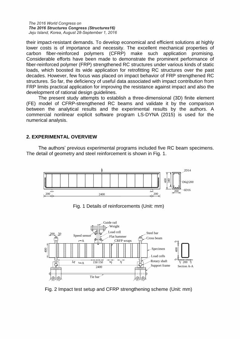
The authors’ previous experimental programs included five RC beam specimens. The detail of geometry and steel reinforcement is shown in Fig. 1.
Fig. 1 Details of reinforcements (Unit: mm)
Fig. 2 Impact test setup and CFRP strengthening scheme (Unit: mm)
D6@200
2400 200200
400
2D14
6D16
340
200
Guide rail
Load cellSpeed sensor
Weight
Flat hammer
CRFP wraps
Tie bar
2400
400
200 50
150150 wf sfldf A
A
200
400
Section A-A
tf tf
t ft f
Cross beam
Steel bar
Specimen
Load cells
Rotary shaft
Support frame

Specimen B1 was unstrengthened as a control specimen, while the rest were completely wrapped with CFRP strips at different reinforcement ratios for shear enhancement. The details of CFRP strips and impact parameters such as drop weight and drop height are given in Table 1, where tf, wf, sf, and ρf represent the thickness, width, center to center spacing, and reinforcement ratio, respectively. All the specimens were tested using a well-instrumented drop weight impact test machine. The schematic diagram of the impact test setup and CFRP fully-wrapping scheme is displayed in Fig. 2. The theoretical flexural resistance Rf and shear resistance Rs under static three-point bend loading are calculated based on ACI 318-14 (2014) and ACI 440.2R2 (2008) as tabulated in Table 1. The value of (Rs / Rf) less than one indicates shear failure. All specimens apart from B5 would be designed to fail in a shear mode under static loading. In Table 1, M is the drop weight and H is the drop height.
Table 1 Details of CFRP strips and static capacities
No Parameters of CFRP strips
Rf (kN)
Rs (kN)
Rs/Rf
Failure modes
M
(kg)
H
(m) tf
(mm) wf
(mm) sf
(mm) ρf
(%)
B1 - - - -
352.86
204.40 0.58 S 383
1.5
B2
0.167 50
200 0.04 262.84 0.74 S 1.5
B3 200 0.04 260.72 0.74 S 513 3.36
B4 100 0.08 320.44 0.91 S 383
1.5
B5 50 0.16 452.38 1.28 F 1.5
The ultimate tensile strength and elastic modulus of unidirectional CFRP sheets were 3561 MPa and 240 GPa, respectively. The average yield and ultimate tensile strengths of all steel bars were 490 MPa and 630 MPa, respectively. The average concrete cylinder compressive strength was 30.0 MPa. 3. NUMERICAL ANALYSIS
The numerical analysis was performed using a software program LS-DYNA in order to develop an analytical method that can rationally predict the dynamic behavior of RC beams strengthened with CFRP strips under impact loading.
3.1 Finite Element Model Bidirectional symmetries facilitate to establish a quarter 3D FE beam model for
saving computing time. An example of FE models is depicted in Fig. 3. The drop weight was simulated by using a simplified cylinder with a mass density equal to the testing impact mass divided by its volume. The initial impact velocity was directly assigned to the cylinder. The real supports were modeled using two support bars placed at the top and bottom of the beam end. One end of the two bars was connected to steel plates

perfectly bonded to the concrete for uniform stress distribution while the other end was pinned as shown in Fig. 3.
A 3D eight-node solid hexahedron element, Solid 164, was used to model the concrete, the drop-weight cylinder, and the steel plates. Steel reinforcing bars including support bars were modeled using a two-node beam element, Beam 161. For CFRP strips, a 2D four-node shell element, Shell 163, was used. All parts were meshed with element sizes ranging from 20 to 25 mm. Perfect bond assumption between concrete and steel rebars or CFRP wraps was implemented.
Fig. 3 A quarter FE model of RC beam 3.2 Material Model The continuous surface cap material model, MAT 159, with a smooth intersection
between the shear yield surface and hardening cap was used to characterize the concrete behavior. The steel rebars were modeled using a strain rate-sensitive uniaxial elasto-plastic material model, MAT 024. The plastic hardening modulus was assumed as 1% of elastic modulus. A linear-elastic orthotropic composite damage material model, MAT 022, was used to model the unidirectional CFRP strips with tensile rupture failure criteria in the fiber direction.
The beam element for support bars utilized the elastic spring-mass material model, MAT 196, with only compressive stiffness. The drop cylinder and steel plate at the support locations implemented the elastic material model, MAT 01, using Young’s modulus and Poisson’s ratio of real steel material. But the drop cylinder was set as a specified mass density as mentioned before.
3.3 Comparison between Numerical and Experimental Results The numerical results are compared with the experimental results to verify the
reliability and accuracy of the FE models in terms of crack patterns and time histories of impact force, reaction force, and midspan deflection.
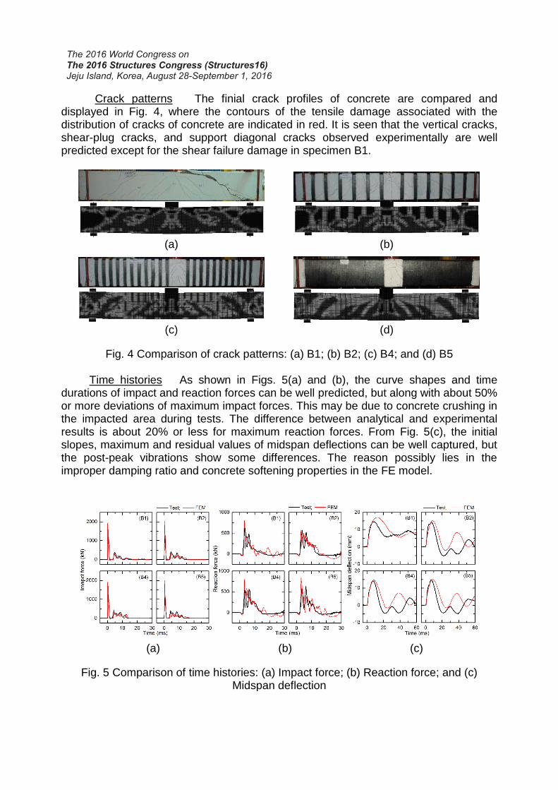
Crack patterns The finial crack profiles of concrete are compared and displayed in Fig. 4, where the contours of the tensile damage associated with the distribution of cracks of concrete are indicated in red. It is seen that the vertical cracks, shear-plug cracks, and support diagonal cracks observed experimentally are well predicted except for the shear failure damage in specimen B1.
(a) (b)
(c) (d)
Fig. 4 Comparison of crack patterns: (a) B1; (b) B2; (c) B4; and (d) B5
Time histories As shown in Figs. 5(a) and (b), the curve shapes and time
durations of impact and reaction forces can be well predicted, but along with about 50% or more deviations of maximum impact forces. This may be due to concrete crushing in the impacted area during tests. The difference between analytical and experimental results is about 20% or less for maximum reaction forces. From Fig. 5(c), the initial slopes, maximum and residual values of midspan deflections can be well captured, but the post-peak vibrations show some differences. The reason possibly lies in the improper damping ratio and concrete softening properties in the FE model.
(a) (b) (c)
Fig. 5 Comparison of time histories: (a) Impact force; (b) Reaction force; and (c) Midspan deflection

4. CONCLUSIONS
To establish an analytical method to understand the impact behavior of RC beams strengthened with CFRP wraps, three-dimensional FE analysis was conducted. The reliability and accuracy of the FE model was validated by comparison between the analytical and experimental results. The comparison shows that the FE model can well predict the crack profiles of beams except for the failure damage. The history curves of impact and reaction forces can be accurately simulated but with some difference for the peak forces. The initial slopes and maximum values of midspan deflection histories can be precisely captured but the post-peak vibration shows some variations. In general, the impact behavior of CFRP strengthened RC beams is well predicted by the proposed FE model. ACKNOWLEDGEMENT
The experimental work in this research was conducted at the Center for Integrated Protection Research of Engineering Structures at Hunan University under the supports of the National Key Basic Research Program of China (973-2012CB026200) and the Thousand-talent National Expert Scholarships. The first author is being supported as a visiting research assistant by Seoul National University where the second author advises the first author.
REFERENCES
ACI Committee 318 (2014), "Building code requirements for structural concrete (ACI 318-14) and commentary," American Concrete Institute, Farmington Hill, MI, 354.
ACI Committee 440.2R-08 (2008), "Guide for the design and construction of externally bonded FRP systems for strengthening concrete structures," American Concrete Institute, Farmington Hills, MI, 31.
LS-DYNA Keyword user’s manual, version R8.0 (2015), Livermore Software Technology Corporation, LSCT.