numerical simulation and analysis of the vertical...
TRANSCRIPT
1
NUMERICAL SIMULATION AND ANALYSIS OF THE VERTICAL AND DOUBLE PIPE
SOIL - AIR HEAT EXCHANGER
Liying LIU1*, Qibin LI
2 , Fali JU
1, Xiukun DONG
1 and Xiaoping YU
1
1. College of Architecture and Civil Engineering, Chongqing University of Science and Technology, Chongqing, 401331, P.R. China
2. College of Aerospace Engineering, Chongqing University, Chongqing 400044, P.R. China
* Corresponding author; E-mail: [email protected]
Abstract: A quasi-three-dimensional soil - air heat and mass transfer model
was established to simulate the process of heat and moisture exchange in the
vertical and double soil-air heat exchanger. At the same time, the heat and
moisture exchange were considered in the model, and the air flow parameter
equation and heat transfer control equation were combined. MATLAB was
used for the calculation procedure, and the model was solved using an
iterative method. The average relative error of the numerical calculation
was less than 2%. Moreover, the heat exchanger performance influence
factors were validated. The simulation results showed that: with the
lengthening of the heat exchanger, the smaller the airflow, the shorter the
running time, the air temperature and moisture content at the outlet of the
heat exchanger were lower, the cooling and dehumidification effect were
more obvious. However, the magnitude of change gradually decreased, and
finally stabilized.
Keywords: Vertical - double pipe; Soil - air heat exchanger; Numerical
analysis; Dehumidification
1. Introduction
The temperature of soil is not constant, is lower than the temperature of outdoor air in summer,
and is higher than temperature of outdoor air in winter. Soil is one of the good and free cold/heat
sources for air conditioning. Ground source heat pump has been investigated experimentally and
numerically in the past few decades[1].The fresh air can also be cooled or heated by the underground
soil, and transferred into the building by mechanical or inductive ventilation system. It is called soil-
air heat exchange system. Internationally, soil-air heat exchange systems are applied to a large number
of hospitals [2], and greenhouses [3]. Locally, they are also extensively applied in theaters, hall [4],
greenhouse [5, 6], subway station [7], museum[8], office[9], building, etc. Research studies show that
they can improve the indoor air temperature, have good benefits for energy conservation and
environmental protection. However, soil-air heat exchanger is always used for cooling the air, and the
soil-air heat exchanger generally consists of horizontal buried tube type and natural tunnel.
A vertical and double pipe soil-air heat exchanger [10] is developed, and tested the cooling and
moisture removing effect of this type of heat exchanger. Figure 1 is the physical model of the soil-air
heat exchanger. The soil-air heat exchanger is made of double tubes. The outer tube is rock hole, with
a diameter of 130 mm. The inner tube is a PVC pipe, and the diameter is 75 mm, and is supported by a
bracket with height of 2 m at the bottom of rock hole. While the heat exchanger is working, fresh air is

2
introduced by the fan into the ring cavity of soil-air heat exchanger, and sent out by inner tube after the
heat and moisture transfer with the rock wall. In summer, the heat and mass transfer process of soil-air
heat exchanger is as follows: the hot and wet air flow into the ring cavity of heat exchanger, and is
cooled by the rock wall. When the temperature of rock wall is lower than the wet air dew point
temperature, wet air would condense and heat and mass transfer will occur between air and rock wall.
When air flows to the bottom of the heat exchanger, it will be sucked into the inner tube and
conducted heat transfer with inside wall of the tube. Heat and moisture transfer between air and rock
will decrease the air temperature in the heat exchanger, and in turn, the temperature of rock face will
be influenced by the air, and the changes of rock face temperature will affect the internal temperature
distribution of rock mass. That is, the hot fresh air will influence the temperature distribution in the
rock mass. The daily amplitude and yearly amplitude of inlet air temperature will affect the heat
exchange process, and interlocking delay phenomenon exists in the whole heat transfer process.
Therefore, heat and mass exchange between air and soil is a complex and unsteady process.
Figure 1. Physical model of soil and air heat exchanger
In order to predict the heat and mass exchange capacity of the vertical and double pipe soil-air
system, this paper established the heat and mass transfer mathematical model of the heat exchanger,
and carried out numerical simulation, it provided a theoretical support for the application of the heat
exchanger in engineering field. Local and international scholars have done a lot of research on the
soil-air heat transfer model. Paepe[11] established a calculation model, the model considered the
fluctuations of the air temperature and the changes of soil temperature and their effect on the heat
convection. In his research, the soil-air heat exchanger is segmented, and outlet air temperature is
obtained by piecewise calculation. Scholars in Shandong Institute of Architectural Design, Mou[12]
established the semi-infinite body steady-state heat transfer model under the boundary conditions of
constant heat flux. The model can predict the supply air temperature under the most unfavorable
conditions of air conditioning system, but it cannot be used to obtain the operation status of the system
in the fluctuation of meteorological parameters, and the algorithm cannot be used to calculate the
annual operation status either. A three-dimensional unsteady heat transfer process of the soil-air heat
exchanger under dry condition is solved by Song[13] of Tsinghua University, and the influence of
various design factors on the heat exchange system are analyzed. South China University of
Technology, Wu et al. [14] dynamically simulated soil-air buried tube heat exchange system based on
turbulence model and soil source conduction equation, using the method of temperature field
superposition; obtained dynamic changes of the air temperature at outlet of the buried pipe, and
3
studied the effect of factors such as buried pipe length(flow rate, pipe diameter )on air temperature at
outlet of heat exchanger. Zhang et al.[15] analyzed the influences of tunnel length,air velocity and
depth on heat transfer between underground tunnel and air in winter through the 3D numerical
simulation.All the above models did not consider the influence of air condensation on the heat
exchange process and on the air humidity at outlet of heat exchanger. C.P.Jacovides and
G.Mihalakakou[16] from the University of Athens established a mathematical model to simulate the
temperature distribution of soil-air thermal exchange system, and did research on the cooling and
heating capacity of the buried pipe system. The model not only considered the heat and mass exchange
in the soil-air heat exchange system, but also considered the thermal stratification naturally. A two-
dimensional model of the buried heat exchanger and three-dimensional transient heat exchange model
were established in cylindrical coordinates, and showed consistency between the simulations and the
experiments. In 2006, Xia et al.[17]studied the heat exchange process of a tunnel ventilation system in
a school, and built a quasi three-dimensional heat and mass transfer model between soil and air,
carried out numerical simulation considering condensate in the heat and mass transfer process, and
finally validated the simulation results with the measured data. Whether air condensation was
considered in the heat transfer process, or whether the air humidity distribution was obtained by
simulation, most of mathematical models and the experiments were both aimed at traditional soil-air
heat exchange system. In this paper, a heat and mass exchange model set up would be for a new
vertical double pipe soil-air heat exchanger which was used for air dehumidification, it could predict
the cooling and dehumidifying capacity.
2. Materials and Methods
2.1. Hypothesis of soil-air heat transfer model
Heat transfer is a complex and unsteady process between air and soil in soil-air heat exchanger.
It needs a long time to compute, and the geometry and physical conditions involved in the process are
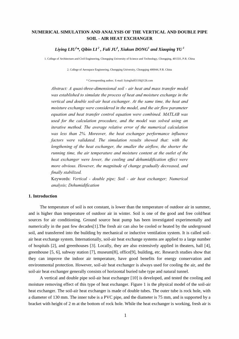
very complex. In order to analyze easily, it is necessary to simplify the problem: 1.Ignoring the heat
transfer between the air in the inner duct and the air in the ring cavity through the wall of inner duct,
assuming that thermal insulation performance of the inner duct is good, only considering the heat and
mass exchange between the air in ring cavity and rock face. 2. Supposing air temperature at similar
cross section is the same, only considering the change of air temperature along the flow direction. 3.
Assuming the initial temperature of soil is not continuously changing with depth, and remains
unchanged within 1 m. The inlet air temperature and humidity is not continuously changing over time,
and remains unchanged within 1h. The calculation model of soil-air heat exchanger is shown in Fig.2.
The control equation and boundary conditions of soil-air heat exchange are listed. Two cases:
condensation and no condensation were considered separately in the thermal balance equation of air.

4
Figure 2. Calculation model
2.2. Soil-air heat transfer mathematic model
2.2.1 Heat conduction equation in the soil shown as Eq. (1)
∂t
∂τ =a[
∂2t
∂r2 +
1
r ∂t
∂r +
∂2t
∂z2 ] (1)
2.2.2 Air heat balance equation[18][19]
When there is no condensed water on the rock face, air heat balance is shown as Eq. (2).
Gc∂T
∂z =h(t|r=r2-T)u (2)
When there is condensed water on the wall, air heat balance is shown as Eq. (3-6).
G[c∂T
∂z +622γ
∂φe
f(T)
B- ef(T)
∂z ]= h(t|r=r2-T)u (3)
φ=d
db ×100% (4)
db=622pq,b/(B- pq,b) (5)
F(T)=ln(pq,b)=C1/T+C2+C3T+C4T2+C5T
3+C6ln(T) (6)
Where C1= -5800.2206, C2=1.3914993, C3= -0.04860239, C4=0.41764768 10-4
, C5= -
0.14452093 10-7
;B is atmospheric pressure,[Pa].
2.2.3 Boundary conditions shown as Eq. (7)
-λ∂t(τ,r)
∂r |r=r2 = h(T-t|r=r2) (7)
2.2.4 Initial conditions shown as Eq. (8-10)
t|τ=0=t0 (8)
T|τ=0,z=0 = T1 (9)
d|τ=0,z=0 = d1 (10)
Where t0 is the initial temperature of soil,[℃] ;where T1 is inlet air temperature ,[K];where d1 is
inlet air humidity ratio, [ g/kg(dry air)].
2.3. Meshing
Calculation areas are selected in two parts: soil section, the annular air cavity between soil and
inner pipe. The category of node is different in different areas. The grids which are divided in
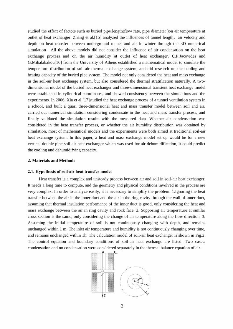
cylindrical coordinates are shown in Fig.3. Soil (rock) area (shadows) is two-dimensional unsteady
heat conduction, thus, meshes are along the radial and vertical direction. In the region of the annular
air cavity, the air temperature is assumed constant along the radial, the grids are divided vertically.
2.4. Model solution
According to the control equations, the heat transfer in the soil is two-dimensional transient heat
conduction, and it is difficult to solve. In order to simplify the solving process, the calculation area
5
along the vertical direction is divided into a number of adiabatic units. The shorter each unit is, the
more accurate of the calculating results are. In each adiabatic unit, it is assumed that the soil and air
temperature are constant along the vertical direction and the heat conduction in the vertical direction is
ignored.
Figure 3. Mesh diagram Figure 4. Ideas of solving the model
The specific process of calculation is shown in Fig. 4. Firstly, at a given time, the node in the
first unit is calculated, the result of the computation is as the boundary conditions of the second unit,
and then the node in the second unit will be calculated. The rest can be calculated in the same manner,
all the grid nodes in all the units will be calculated, and then into the calculation of next level.
The governing equation underwent discretion within each computing element with heat
conduction along Z axis was being neglected. The first-order derivative of temperature versus space
was expressed with forward difference while the second-order derivative with central difference. The
first-order derivative of temperature versus time was expressed with explicit difference. It is necessary
to make sure the coefficients of all the items in the discrete equation are ≥0, or calculated values
would fluctuate at different moments and conclusions against the law of thermodynamics would be
drawn.
It has been assumed that the inlet air temperature is constant within 1h. In order to simplify the
calculation, take a time step is Δτ=10s. In order to ensure the accuracy of the calculation result, the
mesh in the soil region is Δr= 0.05 m.
The soil area is decomposed into multiple units which are adiabatic rocks with each other along
the vertical direction, and taking the length of each unit Δz= 1 m. It does not only ensure the precision
of the calculation, but also accelerate the speed of calculation.
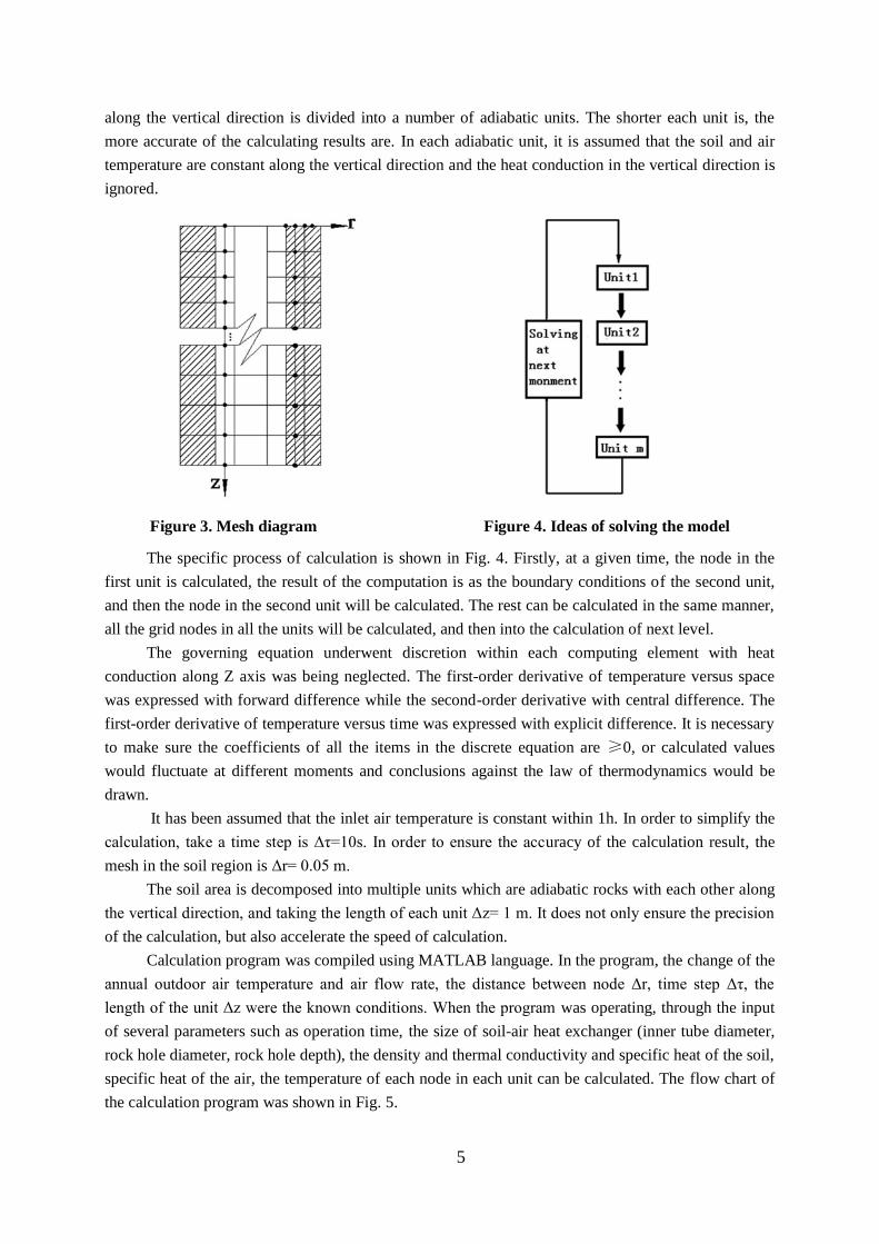
Calculation program was compiled using MATLAB language. In the program, the change of the
annual outdoor air temperature and air flow rate, the distance between node Δr, time step Δτ, the
length of the unit Δz were the known conditions. When the program was operating, through the input
of several parameters such as operation time, the size of soil-air heat exchanger (inner tube diameter,
rock hole diameter, rock hole depth), the density and thermal conductivity and specific heat of the soil,
specific heat of the air, the temperature of each node in each unit can be calculated. The flow chart of
the calculation program was shown in Fig. 5.
6
2.5. Experimental verification
In order to validate the rationality of the model, experimental analysis has been done. The soil-
air heat exchange device is located in the Lab Building of Chongqing University, which is shown in
Fig. 6. The mathematic model was verified through comparing the experimental results and simulation
results.
Figure 5. The flow chart of calculation program
The main geometric parameters and operation parameters of the soil-air heat exchanger are
shown in Tab. 1. Running time was from 28 July 8:00 ~ 11 August 23:00, continuously running 24
hours a day.

7
Figure 6. The room for inducing and exhausting air of soil-air heat exchanger
Table 1. Operating parameters in summer
Parameter r2 r1
z G
Value 0.065 0.0375 23 125
The calculations of numerical simulation used heat and mass transfer model of soil-air heat
exchanger. The basic size and material physical parameters of the heat exchanger are shown in Tab. 2,
and the initial temperature of the soil are shown in Tab. 3. Hourly outdoor air temperature and
humidity ratio are input parameters, which are shown in Fig. 7. Air flow rate in the heat exchanger is
125 m3 / h.
Table 2. Heat exchanger size and soil physical parameters
Parameters r2 r1 z λ, ρ c
Value 0.065 0.0375 23 2.035 2400 0.921
Table 3. Initial soil temperature
Depth, m 1 2 3 4 5 6 7 8
Temperature, ℃ 26.87 24.15 22.08 20.67 19.81 19.38 19.23 19.25
Depth, m 9 10 11 12 13 14 14~25
Temperature, ℃ 19.36 19.5 19.63 19.74 19.83 19.88 19.91
Figure 7. The weather data of Chongqing
3. Results
3.1. Validation results
A comparison of the measured results and simulated results are shown in Fig. 8 and 9. The
variation rule of measured and simulated values at the bottom of hole are consistent during the
operation of the soil-air heat exchanger. The average air temperature measured at the bottom of the
rock hole was 21.36 ℃, average air temperature simulated at the bottom of the hole was 21.74 ℃, the
difference was about 0.3 ℃, and the error between the simulation results and the experimental results
during all the running time was less than 8%. The measured average air moisture content at the bottom

8
of the rock hole was 16.78 g/kg (dry air), simulated average air moisture content at the bottom of the
hole was 16.46 g/kg (dry air), the simulation results was lower than the actual result of 0.3 g/kg (dry
air), and the error between the simulation results and the experimental results during all the running
time was less than 10%.
3.2. The influence of the heat exchanger depth on its performance
The air parameters at the outlet were different for different heat exchanger depths. In order to
investigate the influence of the heat exchanger depth on its performance, the exit air temperature and
humidity ratio were obtained by simulation when the depth of the heat exchanger was 5m, 10m, 15m,
20m, and 25m. Therefore, the cooling and dehumidification ability of the heat exchanger were
calculated as in Fig. 10~11.
Figure 8. Comparison of measured air temperature at the bottom of heat exchanger and
simulated air temperature at the outlet of the heat exchanger
Figure 9. Comparison of measured air moisture content at the bottom of heat exchanger and
simulated air temperature at the outlet of heat exchanger
As it can be seen from Figure 10, the heat exchanger has apparent cooling effect. The cooling
ability was strengthened with the increase of the depth of the heat exchanger. However, with the
increase of depth of the heat exchanger, the rise of cooling ability seems to be fairly smooth. Moreover,
with the increase of operation time, the decrease of the inlet air temperature, the heat exchanger's
cooling ability gradually became smaller. In the running time, 6 days in a row, for the heat exchanger

9
with the depth of 5 m, 10 m, 15 m, 20 m, 25 m, the maximum temperature decrease were 10.3 ℃,
11.8 ℃,13.1 ℃and 14.1 ℃and 14.7 ℃ respectively.
From Fig. 11, it can be seen that the heat exchanger had obvious dehumidifying effect, the
dehumidification capacity increased with increasing depth of the heat exchanger. With the increase of
operation time, inlet air humidity ratio decreased, and desiccant quantity decreased. In the running
time 6 days in a row, for the heat exchanger with the depth of 5 m, 10 m, 15 m, 20 m, 25 m, the
maximum desiccant quantity were 3.9, 6.3, 7.5, 8.0, 8.2 g/kg (dry air).
Figure 10. The variation of cooling ability of heat exchanger with different depth over the
running time
Figure 11. The variation of dehumidification ability of heat exchanger with different depth over
the running time
3.3. The influence of the air volume flow rate on the performance of the heat exchanger
Air volume flow rate influence air velocity in underground heat exchanger, in turn, affecting the
heat transfer coefficient h between soil and air convection, subsequently, they can affect cooling and
dehumidifying capacity of heat exchanger. Heat transfer effects were discussed when air volume flow
rate were 50, 100, 150, 200, 150 m3 / h and heat exchanger size was constant.
As it can be seen from Fig. 12, the drop of temperature decreased with increasing air flow rate,
increased with increasing inlet air temperature. The cooling ability decayed with the increase of
operation time. The greater the air volume flow rate was, the faster of cooling ability decayed. When

10
air flow rate were 50, 100, 150, 200, 250 m3 / h, the maximum temperature drop of the heat exchanger
were 15.4, 15.2, 14.5, 13.7, 12.9 ℃. From Fig. 13, it can be seen that the dehumidification quantity is
reduced with the increase of air flow rate; increased with the increase of the inlet air moisture content,
and reduced with the increase of operation time. The greater the air volume flow rate was, the faster of
the dehumidifying capacity decay. When air flow rate was 50, 100, 150, 200, 250 m3 / h, the
maximum dehumidification capacity of the heat exchanger were 9.0, 8.8, 8.2, 7.8, 7.4 g/kg (dry air).
Figure 12. The variation of cooling ability of heat exchanger with different air volume flow rate
over the running time
Figure 13. The variation of dehumidification ability of heat exchanger with different air volume
flow rate over the running time
4. Discussion and Conclusion
In this paper, the soil-air heat exchanger is used not only for cooling of the fresh air, but also for
air dehumidification. They could be used to cool or pre-dehumidify the fresh air without additional
cooling effects. So the designed soil-air heat exchangers are buried deeper that other earth-tube[20] or
straight and spiral earth-air heat exchangers[21]. In order to investigate the cooling and dehumidifying
capacity, the heat and mass transfer model was established and numerically discretized and solved in
this paper. The mathematical heat and mass transfer model proved correct through the comparison of
numerical results and experiment results. The result indicates that the soil-air heat exchanger has good
11
cooling and also dehumidification ability. The cooling ability is similar to the previous research. The
fresh air temperature drops significantly and decreases until the air temperature becomes equal to soil
temperature. In this paper, the maximum temperature drop is about 16 ℃. In the literature[22], the
maximum temperature drop is about 20.7 ℃. The temperature difference between inlet and outlet is
related to the inlet air temperature, air volume and the length of the heat exchanger. The
dehumidification capacity of vertical soil-air heat exchanger is better than the horizontal soil-air heat
exchanger. That because the Soil temperature is lower and more stable in the depth of 23 m than 1 m.
The maximum water condensation of a horizontal soil-air heat exchanger, on the summer day is only
0.006 kg[23]. In addition, the relationship of the heat exchanger depth (air volume, operation time)
and the exit air temperature (humidity ratio) was obtained by the numerical simulation. The simulation
results show that the temperature drop or dehumidification capacity increases with the increase of heat
exchanger length and increases with the decrease of air volume flow rate and increases with the
operating time. Moreover, the amplitude of the variation gradually become flatter and flatter. The
simulation results can supply a theory basement for the design of vertical double pipe soil-air heat
exchanger applied to different region. In this paper, the mathematic model is not considering the
influence of underground flow. And the thermal properties of soil will also be different because of the
multi-phase nature of the soil. Other types of vertical earth-air heat exchanger can be studied for better
cooling and dehumidification capacity. Further investigation into the impact of these factors is
therefore necessary.
Acknowledgment
This research is funded by Educational Reform Project of Chongqing University and
Technology(201616) , Scientific Research Projects of Chongqing Educational Committee (
KJ1501324).
Nomenclature
a – thermal diffusivity of soil, a=0.33×10⁻²
, [m2/h] c – specific heat of air, [KJ/(kg•K))]
d – air humidity ratio of air,[g/kg(dry Air)] db– air humidity ratio of saturated air, [g/kg(dry
Air)]
de – equivalent diameter=( 2r2-2r1), [m] G – ventilation rate, [kg/s]
h – convective heat transfer coefficient=(0.045λ•Re0.8
/de), [W/m2•K];
pq,b– the partial pressure of saturated steam,[Pa] r1– the outside radius of inner air duct, [m]
r2 – the radius of rock hole, [m] r3– the adiabatic boundary of soil, [m]
r – the distance from some point to the hole center in the soil radial direction , [m] and r≥r3
Re – Reynolds number (=G•de /π(r22-r1
2)ν), [–] t – soil temperature,[℃]
T - air temperature,[℃] u – the perimeter of ring cavity cross-section,
[m]
z – the distance from some point to ground in the depth direction of the hole, [m]
Greek symbols
λ – thermal conductivity of soil, [W/m•K] τ – operation time, [h]
γ– gasification latent heat, [J] φ – air relative humidity ,[%]
ν– coefficient of kinematic viscosity of air, [m2/s]
12
References
[1] Dong X.J.,Gu B.. A novel design method for ground source heat pump,Thermal Science
,18(2014),5,pp.1661-1666
[2] Sodha, M. S., et al., Evaluation of an earth-air-tunnel system for cooling/heating of a hospital
complex, Building and Environment, 20(1985), 2,pp.115-122
[3] Santamouris, M., et al., On the performance of buildings coupled with earth to air heat
exchangers , Solar Energy, 54(1995), 6,pp.375-380
[4] Wang, J., Application of underground tunnel ventilation to air conditioning system for Mogao
Grottoes’Tourist Service Center, HV&AC , 41(2011),10, pp.15-17, 33
[5] Liu, H. , et al., Experiment research of dynamic heat transfer characteristics for earth-air heat
exchanger in greenhouse under coupled heat and moisture transfer, Science Technology and
Engineering , 15(2015), 18,pp. 97-103
[6] Fan,Y. , et al.,The simulation study of the heat transfer characteristics of air-soil heat exchanger,
Renewable Energy Resources , 34(2016), 10,pp.1517-1524
[7] Han, L. C. , et al., Numerical analysis of cooling effect of tunnel ventilation system in subway
station, Refrigeration & Air Conditioning, 30(2016), 1,pp.1-4
[8] Yang, Y. F. , et al., Research on application of earth-to-air heat exchanger in museum building,
Renewable Energy Resources, 32(2014) ,9,pp.1352-1358
[9] Wu, J.T. , et al.,Test study of a building-flesh air-system using earth-air heat exchangers .
Journal of Hebei University of Technology, 43(2014),1 ,pp.82-87
[10] Liu L.Y. , et al., Heat transfer performance of fresh-air handing device using earth energy,
Journal of central south university of technology, 16(2009), S1,pp.259-264
[11] Paepe, M.D. , et al.,Earth-air heat exchangers in the Belgian climate: analysis of the potential
with a 3D modeling technique. Proceedings of the 22nd Annual AIVC Conference, Bath, United
Kingdom, 2001
[12] Mou, L.Q., The calculation and application tunnel wind cooling. China building industry
press, Beijing,China,1982
[13] Song, L., Zhu, Y.X., Simulation study on cooling potential of multi-tube earth-air tunnels,
HV&AC, 39(2009),9 ,pp.66-69
[14] Wu, H.J., et al.,Numerical simulation of flow and cooling performance of the earth-air heat
exchangers. Acta Energiae Solaris Sinica, 27(2006), 1,pp.78-82
[15] Zhang, X.M. , et al., Numerical simulation and analysis about characteristics of heat transfer
between underground tunnel and air in winter. Journal of Shenyang Jianzhu University ( Natural
Science), 31(2015), 1,pp.124-132
[16] Jacovides, C.P., Mihalakakou, G.,An underground pipe system as an energy source for
cooling/heating purposes, Renewable Energy, 6(1995),8 ,pp.893-900
13
[17] Xia C.H. , et al., Numerical simulation and analysis of underground duct system, Acta
Energiae Solaris Sinica, 27(2006),9 , pp.923-928
[18] Zhao R.Y. , et al., Air Conditioning (Fourth Edition), China Building Industry press,2009.
[19] Zhang X.M. , et al., Heat Transfer (Sixth Edition), China Building Industry Press,2014.
[20] Darkwa, J. , et al., Theoretical and practical evaluation of an earth-tube (E-tube) ventilation
system,Energy and Buildings, 43(2011), 2,pp.728–736
[21] Mathur, A. , et al., Comparative study of straight and spiral earth air tunnel heat exchanger
system operated in cooling and heating modes, Renewable Energy , 108(2017), pp.474-487
[22] Belatrache,D. , et al., Numerical analysis of earth air heat exchangers at operating conditions
in arid climates,International Journal of Hydrogen Energy,2016,42,13,pp.8898-8904
[23] Mongkon, S. , et al., Cooling performance and condensation evaluation of horizontal
earthtube system for the tropical greenhouse, Energy and Buildings, 66(2013), pp.104–111
[24]