numerical and experimental study for the prediction of the ... · characterize the hp turbine...
TRANSCRIPT

Numerical and experimental study for the
prediction of the steady, three dimensional flow
in a turbine nozzle vane cascade using
OpenFOAM
Silvia Ravelli*, Giovanna Barigozzi*, Francesco Pasqua**, Roberto
Pieri++, Raffaele Ponzini**
*Department of Engineering, University of Bergamo, Italy
** CINECA, Segrate (MI), Italy
++ SCS Italy, Segrate (MI), Italy

• Who we are
• Motivation & background
• Experimental and numerical setup
• Results and validation against measurements
• Conclusions & future developments
2
Outline

3
EST - Energy Systems and
Turbomachinery Group
Department of Engineering
University of Bergamo, Italy
CINECA
SCS Italy
Who we are

Main goal: exploring the potential of the OpenFOAM Toolbox to characterize the HP turbine section of a gas turbine engine
4
Air-cooled HP Turbine Un-cooled LP Turbine
SGT-750 © Siemens AG 2010
Motivation

5
Experimental and numerical investigation of thermal and aerodynamic performance of linear vane cascade
National Research Projects (PRIN) and Industrial research contracts
Simulations by means of commercial CFD codes
exp. SAS
Exp. Vs CFD boundary layer
Suction-type, open circuit wind tunnel
Background

Current activity
6
CFD modelling
supported by
experiments HPC platforms for CAE applications:
http://www.fortissimo-project.eu/
http://www.prace-ri.eu/
CFD open-source technology for industrial applications

Experimental setup
7
c = 142.1 mm
s/c = 1.04
H = 98 mm X
Y Solid Vane
Operating conditions
H/c = 0.69
2 = 70°
1 = 0
Inlet boundary layer (X/cax = -1.6)
M2is= 0.2
Re2is = 6.5*105
Tu1 = 1.62%

Experimental setup
8
PS
SS 5-hole probe
Instrumented vanes
Experimental data used for validation:
vane loading at midspan (z/H=0.5)
wake total pressure Pt2 (z/H=0.5, x/Cax = 1.50)
kinetic energy loss coefficient z (at x/Cax = 1.53)
100*U
U1
2is2
22
z

Numerical workflow
9
PRE-PROCESSING COMPUTING POST
PROCESSING
SOLVING
HPC ENVIRONMENT
COMPUTATIONAL VISUALIZATION
RESULTS MODEL MODEL
PHYSICAL

– Meshing CAD geometry
– Criteria: checkMesh output & experimental fidelity
– Hybrid mesh topology
– SW: Pointwise (Pointwise Inc.)
10
Meshing

Mesh details
Different meshes were created to assess the sensitivity of the solver setup to the spatial discretization:
11
TOPOLOGY QUALITY SIZE
Mesh name y+ (min – max –
average) BL hexahedra
block BL – # of
layers Max Non-
orthogonality Average Non-orthogonality
Max Skewness Max Aspect
Ratio # of cells [Millions]
hybrid1 15.1 – 113.7 – 60.2 yes 5 43.2 6.1 0.7 6.2 1.6
hybrid2 15.2 – 116.8 – 59.7 yes 5 37.1 6.1 0.7 6.4 2.4
hybrid3 8.0 – 68.0 – 36.1 yes 5 36.9 6.2 0.6 4.6 3.5

Boundary conditions
12
Patch name Patch type
inlet patch
mid symmetryPlane
outlet patch
tip wall
vane wall
periodic* cyclic
Patch name U p
inlet timeVaryingMappedFixedValue zeroGradient
outlet zeroGradient fixedValue

Numerical setup
• Solver: steady state simpleFoam
• Discretization schemes: 2nd order
• Advection term: blended scheme (1st/2nd order)
• Residual control: ending criterion of 10-9
• Monitoring: 14 pressure and velocity probes
• Two-equation turbulence models with WallFunctions approach
13
Mesh name Turbulence model
hybrid1 k-ε
hybrid2 k-ε
hybrid3 k-ε/realisable k-ε/SST k-

Results – Overview
Results will include the following:
• Mesh sensitivity analysis based on midspan flow features Turbulence model: k-ε
• Evaluation of the turbulence model influence on the predictions of: vane load wake loss secondary flows
• Scalability analysis over different HW configurations
14

Results – Mesh sensitivity
15
Best mesh Hybrid3
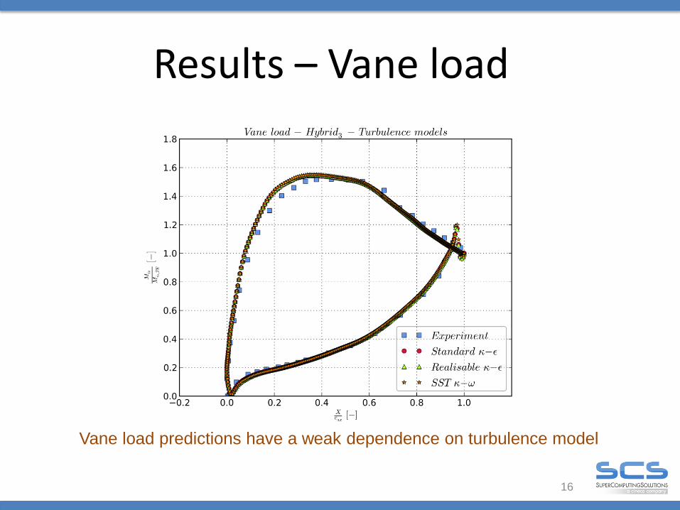
Results – Vane load
16
Vane load predictions have a weak dependence on turbulence model

Results – Midspan velocity
17
Turbulence model marginally affects midpan velocity
(x/Cax= 1.50)
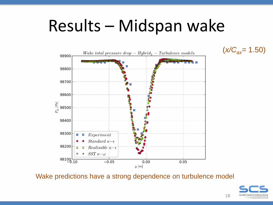
Results – Midspan wake
18
Wake predictions have a strong dependence on turbulence model
(x/Cax= 1.50)

Results – Midspan wake
19
Wake predictions have a strong dependence on turbulence model
(x/Cax= 1.50)

20
Results – Secondary flows (x/Cax= 1.53)
Hybrid3 - Realisable k-e
Experiment
100*U
U1
2is2
22
z
Hybrid3 - SST k-

21
Scalability
Hybrid3 mesh
Nehalem and
Westmere cores are
interconnected with
Infiniband DDR
Sandybridge cores
are interconnected
with Infiniband QDR

• Turbulence model The vane load prediction is satisfactory, especially on the pressure side. Realisable k-ε and SST k-ω are the closest to the measured wake loss, with an
overestimation of 15% and 9%, respectively. Simulations overpredicted the kinetic energy losses associated with the
passage vortex and the corner vortex as well.
• Computational efficiency
The scalability of the study-case is effective on the tested cores range thanks to the HPC platform (HW+Interconnection).
Setup shows a good efficiency (>80%) using up to 38k cells per computational core. This cell density per computational core can be used as reference for the same setup on larger problems.
22
Conclusions

• Pre-processing: Mesh topology based on native openFoam pre-processor
• Compressibility to match experiments at M2is = 0.4 – 0.6
• Thermal modelling to simulate film cooling applications
• Unsteadyness for an accurate prediction of the thermal mixing between mainstream and coolant flow
23
Future developments

Thank you for your kind attention!
24
Questions?