numerical analysis of sliding friction coefficient …s2is.org/issues/v7/n4/papers/paper18.pdf ·...
TRANSCRIPT

INTERNATIONAL JOURNAL ON SMART SENSING AND INTELLIGENT SYSTEMS VOL. 7, NO. 4, DECEMBER 2014
1773
NUMERICAL ANALYSIS OF SLIDING FRICTION
COEFFICIENT AND THE NORMAL PRESSURE BETWEEN
THE CABLE WIRE
1Zhu Hui-ling, 2Zhu Xin-yin, 1Wang Yu-lin 1School of Mechanical Engineering, University of South China,Hengyang, Hunan,421001, China 2The Affiliated Nanhua Hospital of University of South China, Hengyang, Hunan, 421002,China
Submitted: Aug. 19, 2014 Accepted: Nov. 10, 2014 Published: Dec. 1, 2014
Abstract- In this paper, the wire pressing device is designed, the range of true positive pressure, curves
of steel friction coefficient changes with positive pressure. Describe the change trend of friction
coefficient is: with the increasing pressure, friction coefficient of cable parallel wire decreased
significantly, but when the pressure increases to a certain value, the friction coefficient decline is
slowing down, and finally tends to a certain value. The curves of friction coefficient changes with
positive pressure, provides a method and basis for the practical engineering of steel wire in the ultimate
friction shear stress accurately, set up and stay cable as layered slipping model provides important
parameters of bending stress analysis. From the numerical simulation method analyzes the positive
pressure parallel wire between the start. This paper first parallel wire contact problem of two cables are
analyzed with the classical theoretical solution and the FEM software ANSYS, to verify the feasibility,
using ANSYS to solve the contact problem of accuracy and precision. On this basis, the strand steel
beam of contact analysis, the preliminary inquiry arching effect on cable parallel wire.
Index terms: Stay cable; positive pressure arch effect; mechanism; friction coefficient; ANSYS; contact
analysis.
Zhu Hui-ling, Zhu Xin-yin, and Wang Yu-lin, NUMERICAL ANALYSIS OF SLIDING FRICTION COEFFICIENT AND THE NORMAL PRESSURE BETWEEN THE CABLE WIRE
1774
I. INTRODUCTION
The cable as the main load-bearing components of cable-stayed bridge, determines the cable-
stayed bridge's operation. In the past 10 years, some domestic and foreign cable important cable-
stayed bridge because of "sick" work and retired early, make people pay more attention to
durability of the cable, although the domestic research on durability of external cable has been
doing a lot of work, but there are still problems many did not get the desired solve, adversely
affecting the normal operation of the cable, cable-stayed bridge in the design reference period,
also hindered the healthy development of the national economy [1]. According to the engineering
experience, the cable fatigue is the factors influencing the durability of the cable anchorage zone,
and the bending stress concentration is the decisive factor leading to fatigue failure of the cable
end. However, our country in the bending fatigue research level lags far behind the developed
countries [2].
As the main load-bearing components of cable-stayed bridge, the cable on the stiffness and
the economy of the whole cable-stayed bridge structure plays an important role in [3, 13]. But in
recent years, our country some cable-stayed bridge in the bridge design reference period is the
frequent occurrence of cable replacement phenomenon, seriously affected the normal use of in-
service cable-stayed bridge, and brought a huge economic burden, highlights the importance of
cable durability problems. The cable is the main load-bearing components of cable-stayed bridge;
it is accompanied by the cable-stayed bridge system together with the birth, development. With
the development of cable-stayed bridge, the cable-stayed bridge has been developed in the layout
of a variety of ways [4, 5, 14, and 15]. Such as single cable plane, double cable plane, fan form
and radiation type etc. At the same time, because of the complexity of the cable and connection,
stress, cable stayed bridge external medium, so that the cable from the start there are technical
problems of anchorage, fatigue, vibration, with both at home and abroad on these problems of
continuous exploration, the cable will be developed.
For a long time, the cable fatigue analysis, considering only the principal stress and ignored
the local bending stress of [6], however, the bending fatigue stress has important impact on the
fatigue properties of the cable wire. In the recent ten years, the cable bending fatigue (stress
change is caused by the direct cause of fatigue of cable, cable fatigue which by the cable local
bending stress due to the change of known as the cable bending fatigue [7]) problem has attracted
wide attention in the world. In this paper, the cable parallel wire applying positive pressure

INTERNATIONAL JOURNAL ON SMART SENSING AND INTELLIGENT SYSTEMS VOL. 7, NO. 4, DECEMBER 2014
1775
utilization device designed by the authors, the positive pressure applied to actual working
condition of steel cables, the true positive pressure range. Through the determination of the
magnitude of the positive pressure values within this range corresponds to with clean lines,
describing the wire friction coefficient with positive pressure changes: with the increasing
pressure, friction coefficient of cable parallel wire decreased significantly, but when the pressure
increases to a certain value, the friction coefficient decline is slowing down, and the final tends to
a certain value. The change trend of friction coefficient changes with positive pressure, for
practical engineering in the wire between the ultimate friction shear stress f orbital accurately
provides method and basis, establish and cable for the layered slipping model provides important
parameters of bending stress analysis [8].
Method through the experiment and theoretical calculation to determine the existing theories
cannot shear stress accurately calculated on the limit friction between wires, so by the experiment
to determine the ultimate friction shear stress is more practicable. By using the experimental
method to determine the limit of determination of friction shear stress is: through the experiment,
the cable under real operating conditions, scope of internal steel wire by the true positive pressure,
friction coefficient threshold determination. The accurate analysis of visible to the cable in
parallel wire friction coefficient and the normal pressure on the ultimate friction shear stress
determination is very important. But the survey found that, so far, the accurate analysis of cable
parallel wire friction coefficient and the normal pressure, some of the work can not meet the need
to accurately determine the limit friction shear stress. Analysis of the work should be carried out
so that the cable parallel wire friction coefficient and the normal pressure, to accurately determine
the wire between the ultimate shear stress value.
II. WIRE EXTRUSION PRESSURE THEORY AND FINITE ELEMENT SIMULATION
2. 1Overview of the development of the cable technology
Parallel wire cable (PWC) consists of several parallel wire, section does not require is
hexagonal, the number of the steel wire can be selected according to the requirements of stress,
the physical properties and parallel wire strand consistent [9, 10, 11, 12]. For cables longer, in
order to meet the transport requirements (can be wound around a drum), need to make the cable
Zhu Hui-ling, Zhu Xin-yin, and Wang Yu-lin, NUMERICAL ANALYSIS OF SLIDING FRICTION COEFFICIENT AND THE NORMAL PRESSURE BETWEEN THE CABLE WIRE
1776
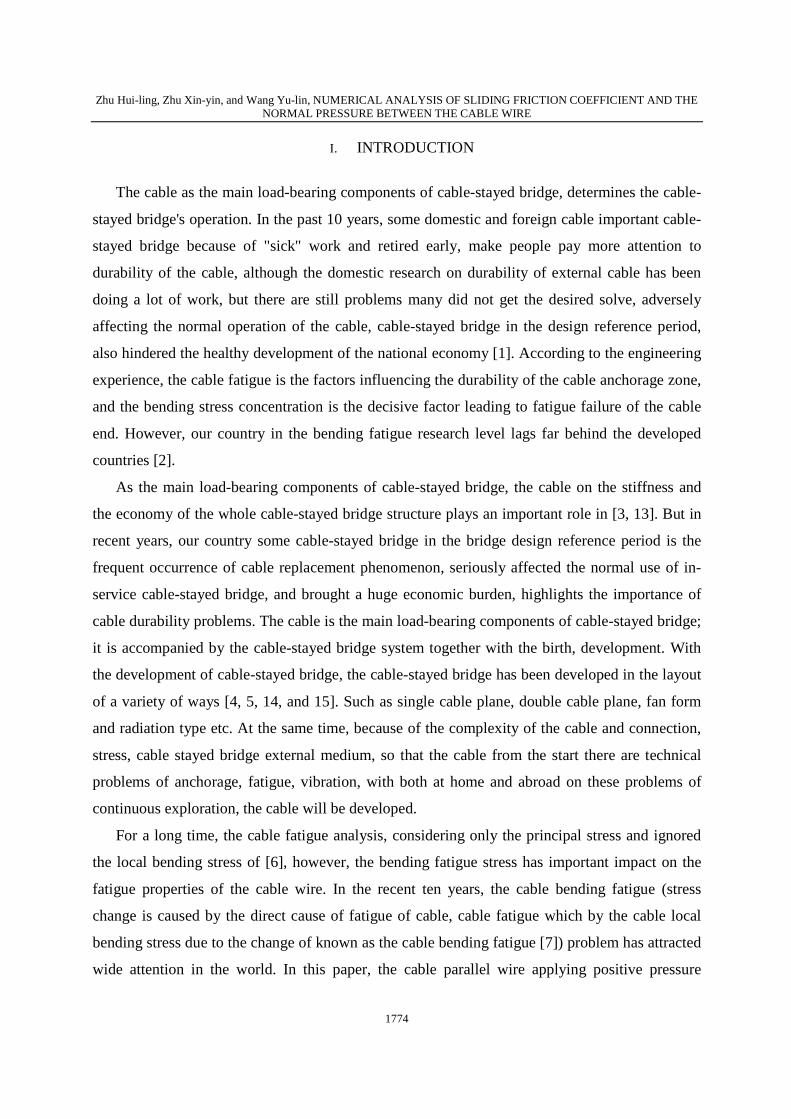
has a twist angle; from the test that twist angle less than 4 degrees can make the elastic modulus
and fatigue damage reduction, the section of regular hexagonal or missing hexagon closely
arranged, the left slightly twisted 2~4 degrees, steel cable outside along the cable length direction
of continuous winding dextral fine steel wire or fiber reinforced polyester belt, the outer squeeze
directly with single or double polyethylene cable sleeve for protection, this is the so-called semi
parallel cable (see Figure 1), the flexural performance is good, can be coiled, with long-distance
transport conditions, suitable for factory machinery production, has replaced the pure parallel
wire cable.
Figure 1. Parallel wire cable schematic cross section structure
2.2Theoretical derivation wire extrusion pressure
Determination of friction coefficient of steel in light weight and small plane loads of the test,
as shown in Figure 2, the uniform slow rotating tight screws to adjust steel grade, when the wire
comes down to stop, the screw rotation height conversion plate lifting angle, anti friction
coefficient μ =tan θ, through adjust the pressure load on the steel tank to required for determining
the wire is pulled pull value size, and then calculate the friction coefficient corresponding to
different pressure.

INTERNATIONAL JOURNAL ON SMART SENSING AND INTELLIGENT SYSTEMS VOL. 7, NO. 4, DECEMBER 2014
1777
Figure 2. Friction coefficient test under the action of gravity
The two experiment data of regression analysis, as shown in Figure 3, a trend of gradual
decrease in linear regression model, but to maintain the level of the basic. The test values are
worth to the size of the coefficient of friction is more reasonable for 0.2108. The experimental
data accord with normal distribution.
Figure 3. Different pressure of friction coefficient of steel wire measurement
2.3The contact problem in elasticity

Zhu Hui-ling, Zhu Xin-yin, and Wang Yu-lin, NUMERICAL ANALYSIS OF SLIDING FRICTION COEFFICIENT AND THE NORMAL PRESSURE BETWEEN THE CABLE WIRE
1778
The cable corrosion includes corrosion cable parallel wire and anchor head rot base.
According to the physical and chemical environment of the cable wire and cable force, wire
corrosion can be divided into: corrosion fatigue, fretting wear candle, stress corrosion, candle and
oxygen etc. The candle is the most common corrosion, stress corrosion is all corrosion types of
destructive and harmfulness of a maximum. The cable wire corrosion is the main reason leading
to cable bearing in reducing stress and residual service life.
According to the current level of technology, in one hundred years of bridge design reference
period, cable-stayed bridge on the need for 4? 5 times for cable, seriously affect the normal use of
the cable replacement costs, design costs that exceed the cable-stayed bridge, putting a heavy
burden on the national economy. With the rapid development of economy, the traffic of the
increasingly high demand, long span cable-stayed bridge has become an urgent need, this puts
forward higher requirements for cable durability technology, and these technologies over the
coverage of existing construction experience and research results, it illustrates the importance of
durability problems research.
III. FINITE ELEMENT SIMULATION OF WIRE TRANSFER MECHANISM
3.1 The contact finite element analysis method
Cable stayed bridge is making specific process is: high strength steel crude material, placed in
the row wire rack, towed by a traction machine, according to drawing, parallel together, after
twisting machine twist, fastening, and then winding steel wire or fiber reinforced slightly twisted
wire strand forming polyester belt, traction steel wire into the plastic extrusion machine, wrapped
in hot extrusion of high density polyethylene, according to the design requirement of precise
feeding, ends of the installation supporting cold cast pier anchor the finished cable. Cable
molding, wire beam mild twist, so that each outer steel wire with spiral wound in the form of
inner steel wire (referred to as "filament"), this time on the cable applied tangential, will be due to
the existence of twist angle to make the internal and external layers of the wire between the
extrusion stress.
INTERNATIONAL JOURNAL ON SMART SENSING AND INTELLIGENT SYSTEMS VOL. 7, NO. 4, DECEMBER 2014
1779
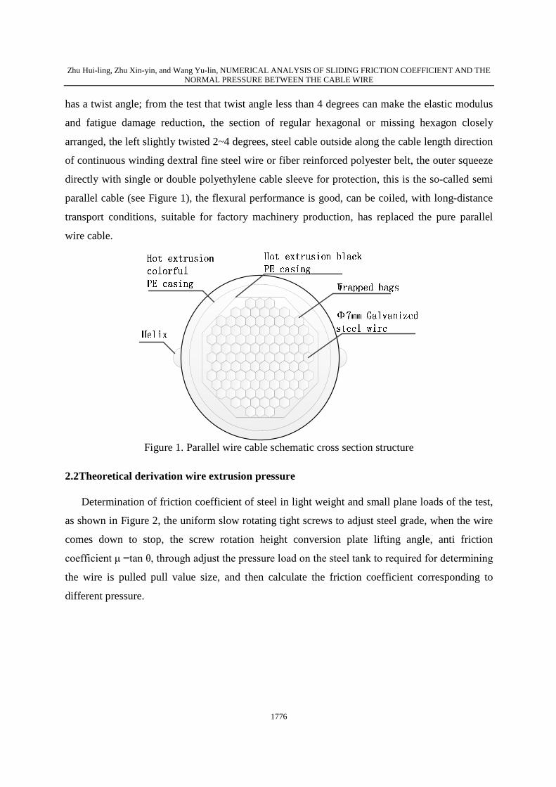
Figure 4. Spiral steel wire stress diagram
As shown in Figure 4, when the wire ends by a tangential force T, radial equivalent line
between the steel wire and the cylinder pressure, set the pitch of the spiral line is L, coiling radius
is r, while helix parameter equation:
cos
sin , [0,2 ]
/ 2
x r t
y r t t
z L t
pp
=ìï = Îíï = ×î
(1)
The parameter t for the helix angle of rotation, the (1) for each type of differential:
sin
cos
2
dx r tdt
dy r tdt
Ldz dt
p
ìï = - ×ï
= ×íïï =î
(2)
The variable Z respectively x, y derivative, and substituted into (2): / 2sin
/ 2cos
dz z Ldx x r tdz z Ldy y r t
p
p
¢ì = = -ï ¢ ×ïí ¢ï = =
¢ ×ïî
(3)
Take half a pitch to force analysis. A tangential force T and xoy of the horizontal angle,
because the equivalent wire and cylinder pressure between the directions of cylinder radial cross
section, is projected onto the xoy plane stress is shown in Figure 5.

Zhu Hui-ling, Zhu Xin-yin, and Wang Yu-lin, NUMERICAL ANALYSIS OF SLIDING FRICTION COEFFICIENT AND THE NORMAL PRESSURE BETWEEN THE CABLE WIRE
1780
cosT a cosT a
a x
y
qdl
dl
xq
yq q
Figure 5. The xoy plane stress
Analysis of the rotation angle of the spiral line alpha dl:
2 2 2 2 2( )2L
dl dx dy dz r dtp
= + + = + (4)
Then: 2 2 242
dl r Ldt
pp+
= (5)
The line angle:
2 2 2 2 2
/ 2sin
( / 2 ) 4
L L
r L r L
pap p
= =+ +
(6)
2 2 2
2cos
4
r
r L
pap
=+ (7)
3.2 Positive pressure finite element simulation
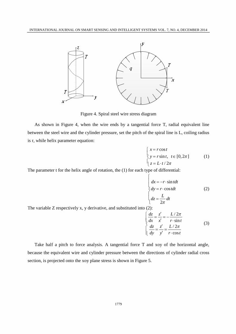
The initial strain element is given by the Δ/L, Δ/L (here is the unit length by node I and J
position to define the difference between the length of zero strain) and L0 (as shown in Figure 6).
For cable options, negative values of strain said in a relaxed state. For breach of options, positive
strain in the split state representation. Here the gap value must be as per unit length value input.
ISTRN is less than 0 and KEYOPT (3) = 0, then the surface is initially slack.
INTERNATIONAL JOURNAL ON SMART SENSING AND INTELLIGENT SYSTEMS VOL. 7, NO. 4, DECEMBER 2014
1781
0d ³ 0d >
0d < 0d £
Figure 6. The initial strain element
Spiral linear modeling outer wire to realize the parameterized modeling to cycle through the
variables in the model does not consider the inner ring, steel wire (wire) deformation, simulation
only outer wire, steel wire radial displacement constraint to the outer ring core wire circle, two
ends of tension through the initial strain, the cooling method of equivalent simulation, general
post processing to extract outer steel wire the radial force, the equivalent node force conversion
cost theory in the derivation of pressure load collection degree Q. The initial strain method, the
cooling method are the establishment of different grid density and contrast model, in order to
compare the theoretical prediction.
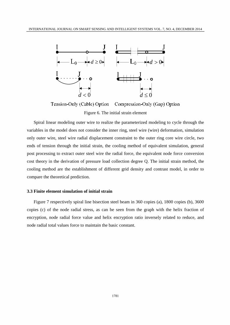
3.3 Finite element simulation of initial strain
Figure 7 respectively spiral line bisection steel beam in 360 copies (a), 1800 copies (b), 3600
copies (c) of the node radial stress, as can be seen from the graph with the helix fraction of
encryption, node radial force value and helix encryption ratio inversely related to reduce, and
node radial total values force to maintain the basic constant.

Zhu Hui-ling, Zhu Xin-yin, and Wang Yu-lin, NUMERICAL ANALYSIS OF SLIDING FRICTION COEFFICIENT AND THE NORMAL PRESSURE BETWEEN THE CABLE WIRE
1782
1 31 61 91 121 151 181 211 241 271 301 331 3616
8
10
12
14
16
18
Node number
Nod
e ra
dial
opp
osite
rea
ctio
n(N
)
The initial strain method of Helical line 360 equal division
Node radial opposite reaction
(a)
1 301 601 901 1201 1501 18011.3
1.5
1.7
1.9
2.1
2.3
2.5
2.7
2.9
3.13.3
Node numberNod
e ra
dial
opp
osite
rea
ctio
n(N
)
The initial strain method of Helical line 1800 equal division
Node radial opposite reaction
(b)
1 301 601 901 1201150118012101240127013001330136010.6
0.8
1
1.2
1.4
1.6
1.8
Node number
Nod
e ra
dial
opp
osite
rea
ctio
n(N
)
The initial strain method of Helical line 3600 equal division
Node radial opposite reaction
(c)
INTERNATIONAL JOURNAL ON SMART SENSING AND INTELLIGENT SYSTEMS VOL. 7, NO. 4, DECEMBER 2014
1783
Figure 7. Spiral line bisection steel beam in 360 copies (a), 1800 copies (b), 3600 copies (c) of the node radial stress
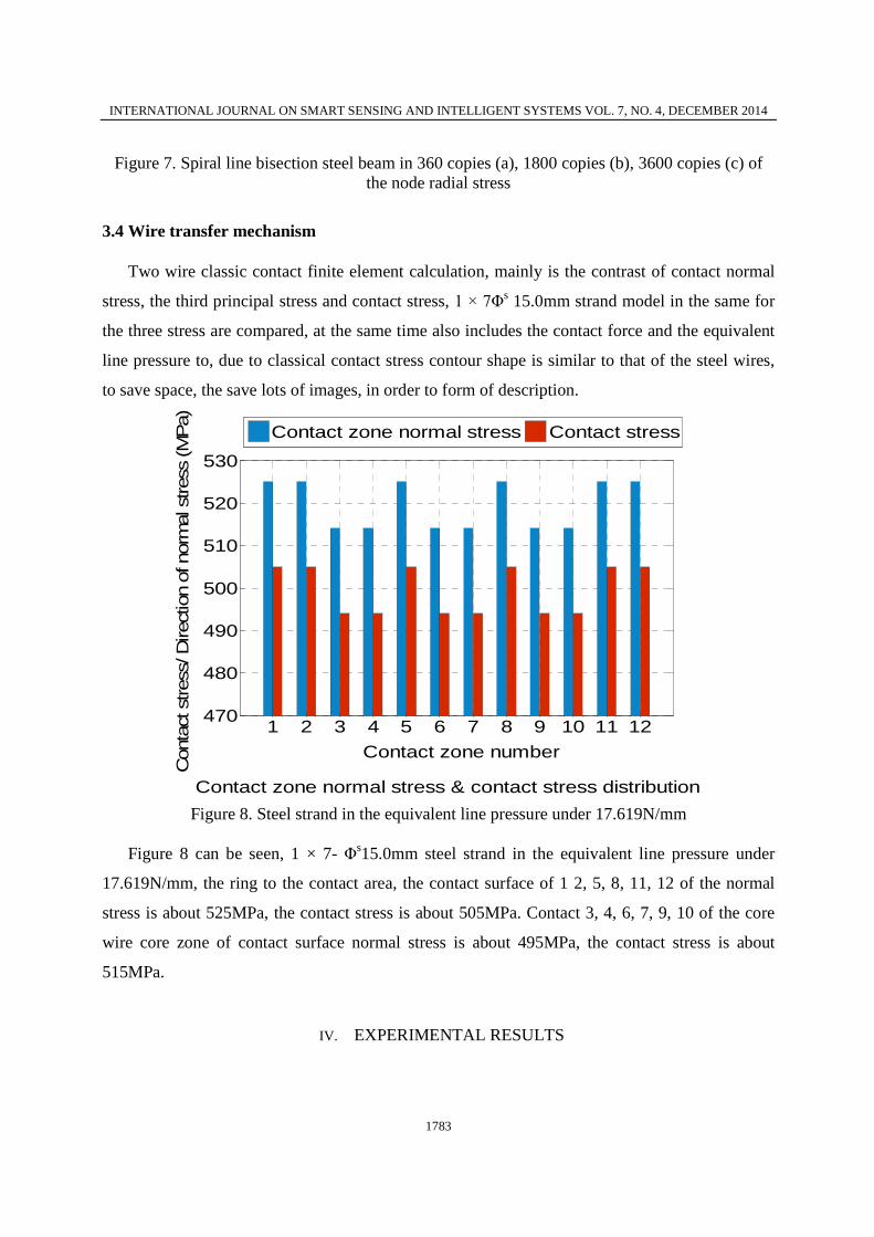
3.4 Wire transfer mechanism
Two wire classic contact finite element calculation, mainly is the contrast of contact normal
stress, the third principal stress and contact stress, 1 × 7Φs 15.0mm strand model in the same for
the three stress are compared, at the same time also includes the contact force and the equivalent
line pressure to, due to classical contact stress contour shape is similar to that of the steel wires,
to save space, the save lots of images, in order to form of description.
1 2 3 4 5 6 7 8 9 10 11 12470
480
490
500
510
520
530
Contact zone number
Con
tact
stres
s/ D
irect
ion
of n
orm
al s
tres
s (M
Pa)
Contact zone normal stress & contact stress distribution
Contact zone normal stress Contact stress
Figure 8. Steel strand in the equivalent line pressure under 17.619N/mm
Figure 8 can be seen, 1 × 7- Φs15.0mm steel strand in the equivalent line pressure under
17.619N/mm, the ring to the contact area, the contact surface of 1 2, 5, 8, 11, 12 of the normal
stress is about 525MPa, the contact stress is about 505MPa. Contact 3, 4, 6, 7, 9, 10 of the core
wire core zone of contact surface normal stress is about 495MPa, the contact stress is about
515MPa.
IV. EXPERIMENTAL RESULTS

Zhu Hui-ling, Zhu Xin-yin, and Wang Yu-lin, NUMERICAL ANALYSIS OF SLIDING FRICTION COEFFICIENT AND THE NORMAL PRESSURE BETWEEN THE CABLE WIRE
1784
4.1Case calculation of theoretical value
Steel strand twisting distance of 12 times the nominal diameter of 16 steel strand. This
chapter selects the strand cables use more 1 × 7- Φs15.0mm cable-stayed bridge as analysis object,
steel wire size allowable deviation of various parameters such as shown in Table 1.
Table 1. Steel wire size allowable deviation of various parameters Steel
Structure Nominal Dia(mm)
Dia tolerant
Strand area(m*m)
Reference quality
9.7 56.3 420 10.8
+0.3 73.7 157
13 99 168 14.8 137 1099 15.7 151 1179
1*7
17.6
-0.2
189 889 12.8 112 1504 15 164 1280 (1*7)C
17.6 +0.4
220 1760
Nominal 7 wire diameter Dn=15.2mm most commonly used steel strand stayed cable section
of the object of analysis in this case, based on the theoretical model, object analysis this section
case as the core wire and twisted in a steel 6 wire on the periphery of the outer ring of the steel
wire, neglecting the effect with the squeeze between layers of steel wire.
4.2 Establishment of the model
Figure 9 is 1 × 7Φs 15.0mm steel strand, the finite element contact model. In order to better
control the quality of grid, the contact area set up multi-layer transition zone, and rotational
symmetry segmentation by plane, grid size from the contact area to the transition zone gradually
smooth transition. The outer and inner layer of wire from top to bottom in turn is divided into 1 to
12 contact zone. 1, 2, 5, 8, 11, 12, six contact zones for peripheral ring to contact area, 3, 4, 6, 7,
9, 10 as the core wire core area of contact.

INTERNATIONAL JOURNAL ON SMART SENSING AND INTELLIGENT SYSTEMS VOL. 7, NO. 4, DECEMBER 2014
1785
Figure 9. The finite element contact model
4.3Finite element simulation analysis of plane finite element models
Finite element simulation of planar model using the PLAN82 element with 8 nodes is 2D,
higher order elements with 4 nodes PLAN82, has higher accuracy for the hybrid grid
quadrilateral and triangular, even the irregular shape. Analysis of two wire contact, adapt to the
circular curve outline border wire appearance or not on the results and the precision of the.
PLAN82 unit of each node has two translational degrees of freedom, can simulate the plane
entity structure, but also can be used as the plane element (plane strain and plane stress), can also
be used as elements.
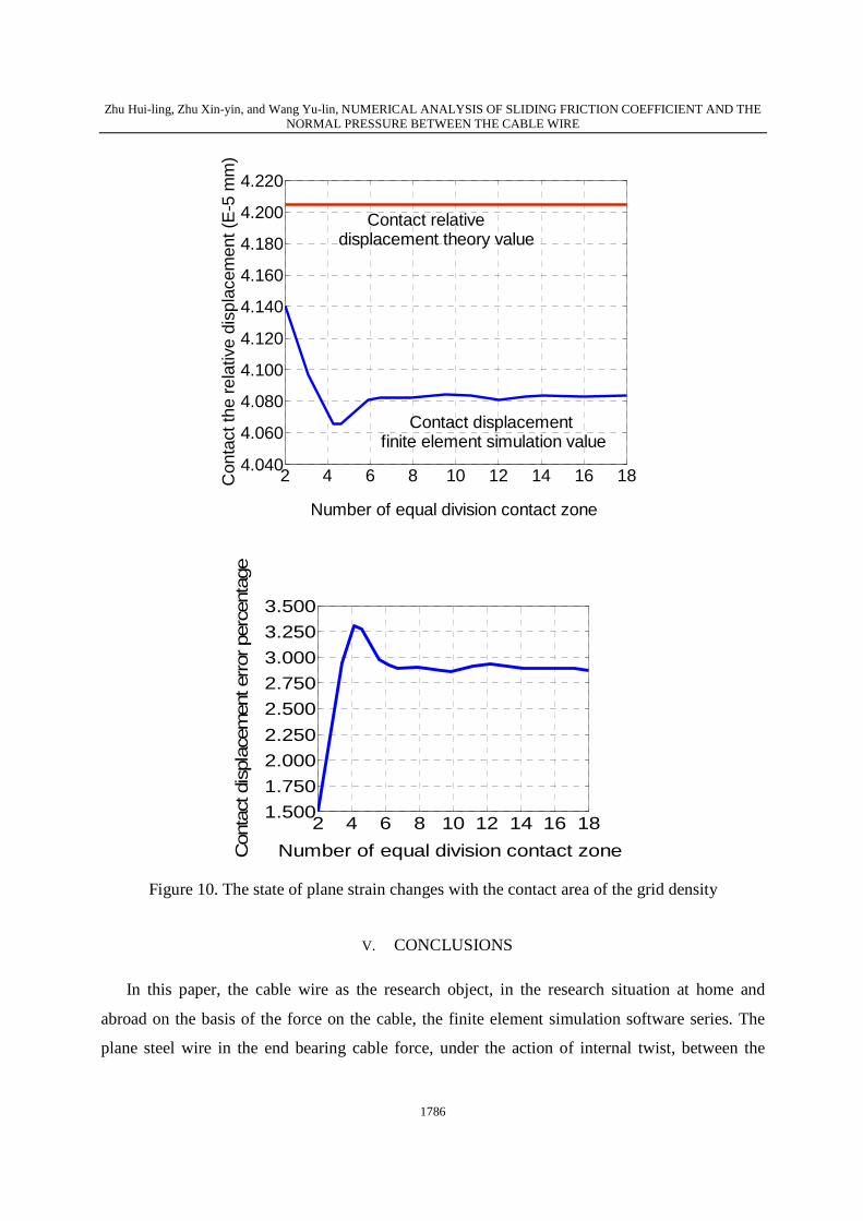
It can be seen in Figure 10, the state of plane strain changes with the contact area of the grid
density, contact relative displacement from 6 parts gradually tends to be stable, with a small
oscillation, but the amplitude of the oscillation is micrometer, the relative error percentage
changes with the grid density final hovering at 2.5%~3%. When the contact area is divided into 2
parts, contact displacement relative error is only 1.5%, but at the contact zone of the unit size is
larger than the contact half width value, the results have some distortion.
Zhu Hui-ling, Zhu Xin-yin, and Wang Yu-lin, NUMERICAL ANALYSIS OF SLIDING FRICTION COEFFICIENT AND THE NORMAL PRESSURE BETWEEN THE CABLE WIRE
1786
2 4 6 8 10 12 14 16 184.040
4.060
4.080
4.100
4.120
4.140
4.160
4.180
4.200
4.220
Number of equal division contact zone
Con
tact
the
rela
tive
disp
lace
men
t (E
-5 m
m)
Contact relativedisplacement theory value
Contact displacement finite element simulation value
2 4 6 8 10 12 14 16 181.500
1.750
2.000
2.250
2.500
2.750
3.000
3.250
3.500
Number of equal division contact zoneCon
tact
dis
plac
emen
t error
per
cent
age
Figure 10. The state of plane strain changes with the contact area of the grid density
V. CONCLUSIONS
In this paper, the cable wire as the research object, in the research situation at home and
abroad on the basis of the force on the cable, the finite element simulation software series. The
plane steel wire in the end bearing cable force, under the action of internal twist, between the
INTERNATIONAL JOURNAL ON SMART SENSING AND INTELLIGENT SYSTEMS VOL. 7, NO. 4, DECEMBER 2014
1787
outer ring wire and core wire equivalent line pressure simulation; by force unit and plane strain
elements of two steel in bridge under the condition of contact stress analysis of fine contrast
should be flat, determine the cable in the actual project contact lower stress; through the 2D
planar grid drag and freedom of network analysis contact, sliding on cable 3D solid elements,
between the mesh quality, quantity of demand in accuracy and balance; the contact wire plane
unit of simulation, the ring to the contact area, core wire core contact force percentage were
studied; stress by comparing the 1 × 7Φs 15.0mm steel and the equivalent line pressure half after
the two steel classical contact, the simplified calculation model for cable 3D entity unit flexural
slip.
REFERENCES
[1] Chatterton, W.J. A green method for cable diagnostics coupled with selective cable
restoration - re-use instead of replace, 2010 IEEE PES Transmission and Distribution
Conference and Exposition, pp.1-4, 2010.
[2] Vejdani-Jahromi, M.; Nagle, M.; Trahey, G.; Wolf, P., Ultrasound Shear Wave Elasticity
Imaging Quantifies Coronary Perfusion Pressure Effect on Cardiac Compliance , IEEE
Transactions on Medical Imaging, Volume: Issue: 99, pp.1-10, 2014.
[3] Sun Quansheng; Yu Haiying et al., Application of Kalman's Filtering Method in
Construction Control for Cable Replacement of the Cable-Stayed Bridge , 2010 International
Conference on Electrical and Control Engineering (ICECE), pp.471 - 475, 2010.
[4] Xiongwei Shi ; Wei Feng, Mechanical analysis of cable-stayed bridge with low towers and its
advancement , 5th Advanced Forum on Transportation of China (AFTC 2009), 239 - 242,
2009.
[5] Xin Li; Li Liang; Kaili Chen, Experimental study on the dynamic properties and dynamic
responses of cable-stayed bridge with steel arched tower 2010 International Conference on
Mechanic Automation and Control Engineering (MACE), pp.4566 - 4570, 2010.
[6] Carstea, I. Carstea, D, An Inverse Problem for Electric Stress in Cable Terminations, 8th
International Conference on Telecommunications in Modern Satellite, Cable and
Broadcasting Services, pp.26-28, 2007.

Zhu Hui-ling, Zhu Xin-yin, and Wang Yu-lin, NUMERICAL ANALYSIS OF SLIDING FRICTION COEFFICIENT AND THE NORMAL PRESSURE BETWEEN THE CABLE WIRE
1788
[7] Sloan, F.; Nye, R.; Liggett, T., Improving bend-over-sheave fatigue in fiber
ropes,Proceedings OCEANS 2003, 1054 - 1057, 2003.
[8] Wei Zhou et al., Testing System for the Friction Coefficient of Airstrip, 2010 International
Conference on Mechanic Automation and Control Engineering (MACE), pp, 5799 - 5802,
2010.
[9] C. Lan;W. Zhou;H. Li, Damage Propagation Monitoring and Fatigue Properties of Parallel
Wire Cable, Proc. SPIE 7294, Nondestructive Characterization for Composite Materials,
Aerospace Engineering, pp. 10-16, 2009.
[10] Krut, Sebastien; Company, O.; Pierrot, F. , Force performance indexes for parallel
mechanisms with actuation redundancy, especially for parallel wire-driven manipulators ,
2004 IEEE/RSJ International Conference on Intelligent Robots and Systems, 2004. (IROS
2004). Proceedings, 3936 - 3941, 2004.
[11] G. Sen Gupta, S.C. Mukhopadhyay, S. Demidenko and C.H. Messom, “Master-slave Control
of a Teleoperated Anthropomorphic Robotic Arm with Gripping Force Sensing”, IEEE
Transactions on Instrumentation and Measurement, Vol. 55, No. 6, pp. 2136-2145, December
2006.
[12] Daode Zhang et al., research on chips’ defect extraction based on image-matching,
International Journal on Smart Sensing and Intelligent Systems, vol. 7, no. 1, pp.321 – 336,
2014.
[13] Quansheng Sun, Xiaoguang Guo, et al.,Research on the application of BP neural network in
construction control for cable replacement of the cable-stayed bridge, 2010 Sixth
International Conference on Natural Computation (ICNC), pp.914 - 918, 2010.
[14] Li Xin, Liang Li, Wang Fuchun,Numerical Simulation of Vibration of Highway Cable-Stayed
Bridge with Steel Arch Tower Due to Moving Vehicle Loads, Advanced Materials
Research,1614-1620, 2011.
[15] Wen, Yongkui, Sun Limin,Parametric Study on Vibration Control Scheme for Steel Tower of
Large Span Cable-Stayed Bridge,Tongji Daxue Xuebao/Journal of Tongji University, vol. 34,
pp.296-301, 2006.