numerical analysis of roller bearing · tapered roller bearing, ... we defined the analysis type...
TRANSCRIPT

5
Applied Computer Science, vol. 12, no. 1, pp. 5–16
Submitted: 2016-02-09 Revised: 2016-03-03
Accepted: 2016-03-11
tapered roller bearing, dynamic simulation, axial load force
Róbert KOHÁR*, Frantisek BRUMERČÍK**,
Michal LUKÁČ***, Aleksander NIEOCZYM****
NUMERICAL ANALYSIS
OF ROLLER BEARING
Abstract
The aim of this paper is to detail the creation of a large tapered roller
bearing model with flexible body cages in the Adams program suite for
subsequent dynamic analysis and to obtain information about kinematic
and dynamic relationships of steel and plastic cages under various
operating conditions. The bearing model was made to closely resemble its
real-life counterpart, which allows us to estimate load conditions, dynamic
conditions of individual bearing parts and interactions between them.
1. INTRODUCTION
Tapered roller bearings are used in shafts which sustain large axial and radial
forces. To achieve high operational reliability and long lifetimes, tapered
bearings have to be set with preload at the time of assembly. Preload allows
to achieve required contact stress between the inner surfaces of the raceway
and the rolling elements. The authors of [1] studied the effect of bearing
assembly on bearing life. As input data they used bearing preload and shaft
deflection angle. Simulation results were expressed in terms of bearing stiffness
and distribution of contact stresses. In addition, modifications were introduced
in the shape of the edge at the base of the cone [2, 3] report the results
* University of Zilina, Faculty of Mechanical Engineering, Univerzitná 1, 010 26 Žilina, Slovakia,
[email protected] ** University of Zilina, Faculty of Mechanical Engineering, Univerzitná 1, 010 26 Žilina, Slovakia,
[email protected] *** University of Zilina, Faculty of Mechanical Engineering, Univerzitná 1, 010 26 Žilina,
Slovakia, [email protected] **** Lublin University of Technology, Faculty of Mechanical Engineering, Nadbystrzycka 36,
20–618 Lublin, Poland, [email protected]
6
of modeling of the impact of operational factors such as angular displacements
of bearing races, shaft deflection, and errors during mounting of ball bearing
assemblies, on service life of a tapered roller bearing. The loadings used were
radial and axial forces at varying rotational speeds. These factors were shown to
effect changes in contact loads and contact stresses between the rolling element
and the races, which led to reduced bearing life. Additionally, an analysis was
conducted of the impact of geometric errors in internal surfaces of tapered roller
bearings [3] on the value of contact forces. Describes the procedures of FEM
modeling of tapered roller bearings which allow to obtain contact stresses [4, 5].
That study presents models of contact stresses and methods of modeling contact
discontinuities on roller and race surfaces.
Tapered roller bearings are also investigated in terms of their material
properties Describes the influence of contact stresses on fatigue spalling
of bearing races, in particular pitting and flaking away of bearing material [6].
It presents the results of FEM modeling based on generating nonlinear material
models, which allows to determine contact stresses. Analyzes the impact of the
internal geometry and micro-geometry of the functional surfaces of raceways
at the contact with the roller and their impact on internal resistance-friction
of the bearing [7].
The above-mentioned studies do not take into account the impact of the
bearing retainer on load bearing capacity and service life of bearings.
The literature also offers no reports on interactions between the retainer
and rolling elements. A bearing retainer moves in rotary motion, and errors in its
manufacture affect the life of rolling elements. Another variable that could be
investigated is the type of material the retainer is made of and its impact on the
value of stresses on the surfaces of the rolling elements.
2. TAPERED ROLLER BEARING MODEL
Dynamic simulations of the tapered roller bearing were performed in the
MSC.Adams system. A precise geometrical model of the bearing was necessary
in order to perform the said simulations. The 3D model has been created based
on available drawing documentation and incorporates various methods with
regards to the overall model complexity. Model design was performed
in Pro/Engineer Wildfire 5 (Fig. 1), which, when compared to the MSC.Adams
environment, allows simpler model creation and subsequently easier bearing
geometry modifications. The bearing model assembly was transformed from
Pro/Engineer into Adams environment using the Parasolid file format and was
further processed based on analysis requirements. The first step included
material definition for individual bearing components. The bearing consisted
of inner and outer ring, cage and rollers. Table 1 lists values assigned
to individual parts.

7
Tab. 1. Material properties of individual bearing parts
[source: own study]
Density
[kg.m-3]
Young
modulus
[MPa]
Poisson
constant[-]
Inner ring 7850 202000 0.29
Outer ring 7850 202000 0.29
Roller 7850 202000 0.29
Steel cage 7850 202000 0.29
Plastic cage 1100 3000 0.42
Fig. 1. Tapered roller bearing model in Pro/Engineer [source: own study]
In the next step we defined the contacts between individual bearing
components. Contact type „solid to solid“ was chosen for the afore mentioned
operation, defining two objects coming into contact. This was due to the
geometrical complexity of the model and inability to determine all bearing parts
that come into contact [8, 9]. This contact type requires the definition of the
following parameters: Stiffness, Exponent, Max Damping and Penetration
Distance. Contact pairs were formed between inner ring and rollers, outer ring
and rollers and between ring and rollers. Parameter values for contacts of rollers
with outer and inner ring have been defined based on the Hertz theory of contact
pressure. We also considered a friction model based on Coulomb friction force
calculation. Values of static and dynamic friction coefficient have been set
according to and values of transmission velocity.
Next we defined the geometric and kinematic constraint conditions and load
force. Axial load force of the outer ring was associated with „Fixed joint“
constraint, which resulted in removal of all degrees of freedom. Inner ring was
associated with „Cylindrical Joint“ constraint condition, which allowed rotation
and translation along the x axis. „Rotational Joint Motion“ of type „Velocity“ has
been assigned to the „Cylindrical Joint“ constraint, allowing rotational movement.
8
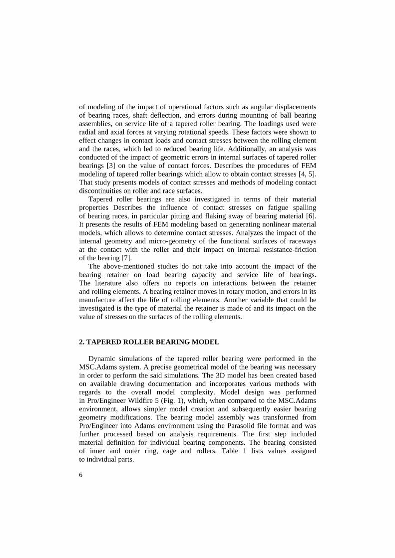
This movement has been defined via the STEP function and corresponds
to bearing rotational speed n = 15.5min-1 and n = 250min-1. Loading force was
defined via gravitation acceleration „Gravity“ and „Axial Force“ of magnitude
518000 N in x axis direction, influencing the inner ring. Figure 2 shows a model
with axial load force with defined geometrical and kinematic constraint
conditions.
Fig. 2. Geometric and kinematic constraint conditions –
axial load force [source: own study]
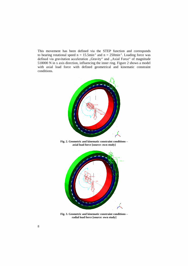
Fig. 3. Geometric and kinematic constraint conditions –
radial load force [source: own study]

9
Constraint conditions for dynamic analysis with radial load force have been
defined as following: „Revolute Joint“ has been assigned to the inner ring and
allowed inner ring rotation around the x axis. „Translational Joint“ has been
assigned to the outer ring, allowing movement in direction of the y axis.
„Rotational Joint Motion“ of type „Velocity“ has been assigned the
aforementioned constraint, allowing rotational movement. This movement has
been defined in a similar fashion as described above using the STEP function.
Load force was defined via gravitation acceleration „Gravity“ and „Radial
Force“ of magnitude 4500000N has been applied in y axis direction, influencing
the outer ring. Figure 3 shows the model under radial load force with defined
geometric and kinematic constraint conditions.
After defining all constraint conditions, boundary conditions and load force,
we defined the analysis type and solver parameters as follows:
SIMULATE/DYNAMIC, END=30, STEPS=3000, Integrator GSTIFF, Formula-
tion SI2, Corrector Modified, Error 1e-3, Executable External C++, Thread
Count 8, Contacts Default_Library, Faceting Tolerance 1e.
3. DYNAMIC SIMULATION RESULTS – AXIAL LOAD FORCE
WITH ROTATIONAL SPEED n = 15.5 rpm
Dynamic simulation results with axial load force and rotational speed
n = 15.5 rpm represent force interactions between individual bearing parts,
movement of bearing cage center of gravity and angular velocity thereof.
Figure 4 shows forces between roller and cage, roller and inner ring and angular
velocity of this roller. Maximum force between steel cage and rollers was
observed during interaction of the cage with roller n.26 and is equal to 268 N
(Fig. 4 up, green line). Also shown is the force between inner ring and roller n.
26 (red line), which varied between 54297 N and 59103 N, a difference of 4.2%
(minimal force) and 8.1% (maximal force) when compared to theoretical
calculations. The blue line displays angular velocity of roller n. 26 and varies
between 483°/s and 495°/s.
Maximum force between plastic cage and rollers was observed during
interaction of the cage with roller n.2 and is equal to 251N (Fig. 4 down, green
line). Also shown is the force between inner ring and roller n. 2 (red line), which
varied between 54467 N and 58636 N and was lower when compared to the steel
cage, representing a difference of 3.9% (minimal force) and 7.1% (maximal
force) when compared to theoretical calculations. The blue line displays angular
velocity of roller n. 2 and varies between 483°/s and 495°/s, similar to the
velocity observed for the steel cage.

10
Fig. 4. Force interaction between inner ring and rollers (red lines), force interaction between
cage and rollers (green lines) and angular velocity of rollers [source: own study]
Figure 5 shows the center of gravity location in the y-z plane of steel cage
oriented as per Fig. 2. Figure 6 shows the center of gravity location in the y-z
plane of plastic cage, fig. 7 shows force interaction between inner ring and rollers.

11
Fig. 5. Movement of center of gravity of steel cage in the y-z plane
under axial load [source: own study]
Fig. 6. Movement of center of gravity of plastic cage in the y-z plane
under axial load [source: own study]

12
Fig. 7. Force interaction between inner ring and rollers [source: own study]
4. RADIAL LOAD FORCE WITH ROTATIONAL SPEED n = 15.5 min-1
Similar to axial load force, we calculated force interactions between
individual bearing parts, movement of bearing cage and angular velocity thereof
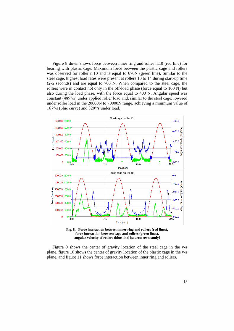
when subjected to radial force. Figure 8 shows force between roller and cage,
roller and inner ring and angular velocity of the roller. Also shown is the force
between inner ring and roller n.13 (red line). Maximum force between steel cage
and rollers was observed for roller n.13 and is equal to 706N (green line).
The analysis also showed that highest load rates are present at rollers 10 to 14
during start-up time (2-5 seconds) and are equal to 700N. During subsequent
simulation time, the cage was in contact with rollers only when the rollers were
off-loaded and maximum force value was equal to 250N. Angular speed was
constant (489°/s) under applied roller load and lowered under roller load in the
20000N to 70000N range, achieving a minimum value of 445°/s (blue curve).
13
Figure 8 down shows force between inner ring and roller n.10 (red line) for
bearing with plastic cage. Maximum force between the plastic cage and rollers
was observed for roller n.10 and is equal to 670N (green line). Similar to the
steel cage, highest load rates were present at rollers 10 to 14 during start-up time
(2-5 seconds) and are equal to 700 N. When compared to the steel cage, the
rollers were in contact not only in the off-load phase (force equal to 100 N) but
also during the load phase, with the force equal to 400 N. Angular speed was
constant (489°/s) under applied roller load and, similar to the steel cage, lowered
under roller load in the 20000N to 70000N range, achieving a minimum value of
167°/s (blue curve) and 320°/s under load.
Fig. 8. Force interaction between inner ring and rollers (red lines),
force interaction between cage and rollers (green lines),
angular velocity of rollers (blue line) [source: own study]
Figure 9 shows the center of gravity location of the steel cage in the y-z
plane, figure 10 shows the center of gravity location of the plastic cage in the y-z
plane, and figure 11 shows force interaction between inner ring and rollers.

14
Fig. 9. Movement of center of gravity of steel cage in the y-z plane
under radial load [source: own study]
Fig. 10. Movement of center of gravity of plastic cage in the y-z plane
under radial load [source: own study]

15
Fig. 11. Force interaction between inner ring and rollers [source: own study]
5. CONCLUSION
Based on obtained results, we can conclude that the steel cage is more
appropriate for axial force load due to lower interaction force between the cage
and rollers. Also reduced are bearing oscillations in both the rotation axis
and in the plane normal to the said axis. Forces between rollers and bearing rings
are minimally influenced by the cage type. This is also true for the angular
velocity of the rollers. Radial force load results in reduced load of steel cage
at lower speed, however at higher speed the plastic cage is more appropriate.
At lower speed, the angular velocities of bearing rollers with steel cage are
randomly changing during the offload phase and could result in undesirable
behavior of the bearing. Angular velocities of plastic cage rollers exhibit
a smoother behavior when compared to steel cage. Additionally, oscillations
in the plane normal to the rotational axis are also lowered.
Based on the afore-mentioned results, we can conclude that the use of plastic
cage is more appropriate for radial load force scenarios.

16
REFERENCES
[1] VAN-CANH T., HONG S.: Characteristics of tapered roller bearings in relation to roller
profiles. Journal of Mechanical Science and Technology, 29 (7), 2015, p. 2913–2919.
[2] VAN-CANH T., HONG S.: Fatigue life of tapered roller bearing subject to angular
misalignment. Proceedings of the Institution of mechanical engineers. Part C – Journal
of Mechanical Engineering Science, 230 (2), 2016, p. 147–158.
[3] VAN-CANH T., HONG S.: Characteristics of Tapered Roller Bearing with Geometric
Error. International Journal of Precision Engineering and Manufacturing, 16 (13), 2015,
p. 2709–2716.
[4] YANG X., HUANG Q., YAN C.: Analyzing the load distribution of four-row tapered
roller bearing with Boundary Element Method. Engineering Analysis with Boundary
Elements, 56, 2015, p: 20–29.
[5] KOHÁR R., MEDVECKÝ Š., HRČEK S.: Usage of dynamic analysis to determine force
interactions between components of rolling bearings with different rotation speed.
In: Machine Design, 4 (3), 2012, p. 145–150.
[6] LOSTADO R., FERNANDEZ M., MAC DONALD B.: Determination of the contact
stresses in double-row tapered roller bearings using the finite element method,
experimental analysis and analytical models. Journal of Mechanical Science and Te-
chnology, 29 (11), 2015, p. 4645–4656.
[7] JURKO J., PANDA A., VALICEK J.: Study on cone roller bearing surface roughness
improvement and the effect of surface roughness on tapered roller bearing service life
International Journal of Advanced Manufacturing Technology, 82 (5-8), 2016, p. 1099–1106.
[8] HARRIS T. A., KOTZALAS M. N.: Essential Concepts of Bearing Technology.
5. edition. 2007.
[9] GLOWACZ A.: Diagnostics of DC and Induction Motors Based on the Analysis
of Acoustic Signals. Measurement Science Review, 14 (5), 2015, p. 257–262.