nuclear regulatory commission contract n rc-02-93-005
TRANSCRIPT

-~ ~ ~ ~ ~ ~ ~ ~ ~ ~ ~ ~~~~~~~~~~
Prepared for
Nuclear Regulatory CommissionContract N RC-02-93-005
Prepared by
Center for Nuclear Waste Regulatory AnalysesSan Antonio, Texas
April 1995

DRAFT SAFETY EVALUATION REPORT ON THEVITRIFICATION PROCESS AND
HIGH-LEVEL WASTE INTERIM STORAGE
REVIEW OF WVNS-SAR-003, REVISION 2, DRAFT D
Prepared for
Nuclear Regulatory CommissionContract NRC-02-93-005
Prepared by
Emil "Chuck" TschoepeDaniel J. Pomerening
Prasad K. Nair
Center for Nuclear Waste Regulatory AnalysesSan Antonio, Texas
April 1995
PREVIOUS REPORTS IN SERIES
Number Name Date Issued
CNWRA 91-015 "Safety Evaluation Report on the West ValleyDemonstration Project Supernatant Treatment System"Safety Analysis, Volume m (WVNS-SAR-004, Rev. 6)
November 1991
CNWRA 93-007
CNWRA 93-008
Seismic/Tornado Analysis Review for the VitrificationFacility at West Valley
Review of Corrosion Aspects of High-Level WasteStorage Tanks at West Valley
April 1993
April 1993
Letter Report Review of the West Valley THOREX WasteNeutralization Process
September 1994
ii

ABSTRACT
This safety evaluation report (SER) reviews the radiological safety aspects of design and operation of theVitrification Process (VP) and High-Level Waste Interim Storage (HLWIS) at the West ValleyDemonstration Project (WVDP) in West Valley, New York, as documented in the Safety Analysis ReportWVNS-SAR-003, Revision 2, Draft D. The VP is being undertaken to transform the liquid inventory ofradioactive high-level waste into a more stable and less hazardous waste form-canistered borosilicateglass.
The SER provides background information on the WVDP facilities with respect to modifications madefor the VP and HLWIS. Radiological hazards are discussed, and those factors governing design areidentified as seismic loads and tornadoes and tornado-generated missiles, for most radiologically importantstructures, systems, and components. The design philosophy at the WVDP is reviewed as it relates tomultiple barriers for control of radiological contamination, use of ventilation zones for direction ofairborne contamination away from occupied areas, defense-in-depth, and as-low-as-is-reasonably-achievable (ALARA). Individual systems and components within the scope of WVNS-SAR-003 arereviewed with respect to margins of safety and incorporation of key design concepts. Radiological dosesfor normal operations, design basis events, and beyond design basis events are reviewed with respect toWVDP evaluation guidelines and NRC-established permissible levels. Administrative features of VPoperations and programmatic considerations are also reviewed. Conclusions from the review indicate thatno comments remain open that are critical to the safe operation of the facility.
iii

CONTENTS
Section Page
FIGURES ...................TABLES ...................ACRONYMS AND ABBREVIATIONSACKNOWLEDGMENTS.QUALITY OF DATA ..........EXECUTIVE SUMMARY ........
..................
..........................................................................................
.....
vii
.... viii
..... .ix...
.. xi
..... .xi.xiii
.... X1-1
.... 1-1
.... 1-2
.... 1-3
.... 1-7
1 INTRODUCTION .....................................1.1 PURPOSE ......................................1.2 BACKGROUND/HISTORY OF THE FACILITY .............1.3 DESCRIPTION OF THE VITRIFICATION FACILITY .........1.4 OUTLINE OF SAFETY EVALUATION REPORT PRESENTATION
2 SAFETY ANALYSIS REPORT AND SUPPORTING DOCUMENTATION REVIEW .... 2-12.1 ADEQUATE CONTROL OF HAZARDS ........................... 2-1
2.1.1 Identification of Hazards ............................... 2-22.1.1.1 Seismic Loads . ..................................... 2-52.1.1.2 Tornado Loads and Tornado Missiles ...................... 2-132.1.2 Design Features .................................... 2-142.1.2.1 Design Philosophy .................................. 2-172.1.2.2 Seismic Design Considerations ........................... 2-212.1.2.3 Tornado and Tornado Missiles Design Considerations ... ......... 2-252.1.2.4 Passive Confinement Systems ........................... 2-262.1.2.5 Active Confinement Structures, Systems, and Components ... ...... 2-272.1.3 Evaluation of Specific Structures, Systems, and Components .. ...... 2-272.1.3.1 High-Level Waste Transfer System ........................ 2-272.1.3.2 Cold Chemical System ................................ 2-312.1.3.3 Confinement Structures ............................... 2-322.1.3.4 Concentrator Feed Make-up Tank, Melter Feed Hold Tank, Submerged
Bed Scrubber ...... ............................... 2-372.1.3.5 Slurry-Fed Ceramic Melter ............................. 2-382.1.3.6 Solid Waste Stream Components ......................... 2-392.1.3.7 Gaseous Waste Stream-Process Off-Gas System ... ............ 2-452.1.3.8 Gaseous Waste Stream-Heating, Ventilation, and Air Conditioning
System ......................................... 2-522.1.4 Administrative Features ............................... 2-602.1.4.1 General Controls ................................... 2-602.1.4.2 Safety Implications and QA ............................ 2-612.1.4.3 Human Factors .................................... 2-61
2.2 WASTE MANAGEMENT .................. 2-622.2.1 Gaseous Wastes .................. 2-622.2.2 Liquid Wastes .................. 2-632.2.3 Solid Wastes .................. 2-63
v
CONTENTS (cont'd)
Section Page
2.3 OPERATIONAL DOSES ......................2.3.1 Radiological-On-Site .................2.3.2 Radiological-Off-Site. ................
2.4 ACCIDENT ANALYSIS ......................2.4.1 Accident Analysis Evaluation Guidelines .....2.4.2 Process Hazard Analysis ...............2.4.3 Radiological Evaluation Basis Accidents ......2.4.4 Beyond Design Basis Accidents ...........
3 OTHER SAFETY CONSIDERATIONS .................3.1 OTHER DESIGN AND OPERATIONAL FEATURES3.2 SPECIAL STUDIES .........................
3.2.1 Criticality .........................3.2.2 Corrosion ......................3.2.3 Seismic Re-Evaluations ................
3.3 TESTING, MONITORING, AND LEAK DETECTION
............ .2-64............
2-64
2-652-652-652-682-692-70
. . . . . . . . .. . . . . . . . .. . . . . . . . .. . . . . . . . .. . . . . . . . .. . . . . . . . .. . . . . . . . .
3-13-13-23-33-33-43-4
4 PROGRAMMATIC CONSIDERATIONS ................. 4-1
5 CONCLUSIONS AND RECOMMENDATIONS ........................5.1 DESIGN PHILOSOPHY ...................................5.2 SEISMIC ANALYSIS .....................................
5-15-15-1
5.2.1 Seismic Analysis for Confinement Barriers .................... 5-25.2.2 Seismic Analysis for Other Structures, Systems, and Components ... ... 5-2
5.3 ANALYSIS FOR MARGINS AGAINST TORNADOES AND TORNADO-GENERATED MISSILES ................. .................... 5-3
5.4 ADMINISTRATIVE CONTROL ...... ............ . 5-35.5 WASTE STREAMS ......................................... 54
5.6 RADIOLOGICAL ON-SITE AND OFF-SITE DOSES ................... 5-4
5.7 ACCIDENT ANALYSIS ............................. . 5-5
5.8 CRITICALITY ..................... ....................... 5-6
5.9 CORROSION ..................... ........................ 5-6
6 REFERENCES ................................................ 6-1
vi
FIGURES
Figure Page
1-1 Vitrification facility flow diagram (WVNS-SAR-003, Rev. 2, Draft D, Fig. C.6-1) ... 1-4
2-1 Fractile seismic hazard curves (Dames & Moore, 1983) .................... 2-72-2 Electric Power Research Institute Methodology-West Valley Demonstration Project
versus Ginna mean probability curves (rock site) (Dames & Moore, 1995) ........ 2-102-3 Comparison of response spectra (Dames & Moore, 1995) .................. 2-122-4 Overview of earthquake analysis steps (Elder, 1986) ..................... 2-232-5 Overview of the high-level waste transfer system (Dames & Moore, 1994b) ... .... 2-282-6 Process off-gas system flow (WVNS-SAR-003, Rev. 2, Draft D, Fig. C.6.3.2-2) . .. 2-462-7 Ex-cell off-gas system components (WVNS-SAR-003, Rev. 2, Draft D, Fig.
C.5.4.1.1-3). 2-492-8 Ventilation zones of the vitrification facility (WVNS-SAR-003, Rev. 2, Draft D, Fig.
C.5.4.1.1-1) .2-532-9 Public radiological evaluation guidelines (WVNS-SAR-003, Rev. 2, Draft D, Fig.
C.2-1) .2-662-10 On-site radiological evaluation guidelines (WVNS-SAR-003, Rev. 2, Draft D, Fig.
C.2-2) .2-67
Vii

TABLES
Table Page
2-1 Comparison of bedrock peak ground acceleration at a probability of 5 x 10⁻⁴ /yr (fromDames & Moore, 1995) ...................... 2-9
2-2 Ginna Rock Site Median pseudovelocity at 5 x 10- 4/yr probability (from Dames &Moore, 1995) ..... 2-9
2-3 West Valley Demonstration Project soil site ground motion spectra (from Dames &
Moore, 1995) ..... 2-112-4 Safety classes, Q-levels, and codes and standards (from West Valley Nuclear Services
Co., Inc., 1994d, Table 2.3 of WVDP-204) ..................... . 2-20
2-5 Off-gas system design data (WVNS-SAR-003, Rev. 2, Draft D, Table C.6.3.1-1) ... 2-47
viii

ACRONYMS AND ABBREVIATIONS
ACI American Concrete InstituteAISC American Institute of Steel ConstructionALARA As Low As is Reasonably AchievableANS American Nuclear SocietyANSI American National Standards InstituteASCE American Society of Civil EngineersASME American Society of Mechanical EngineersBDBA Beyond Design Basis AccidentBDBE Beyond Design Basis EarthquakeCC Chilled Water SystemCCB Cold Chemical BuildingCCS Cold Chemical SystemCFMT Concentrator Feed Make-up TankCMR Crane Maintenance RoomCNWRA Center for Nuclear Waste Regulatory AnalysesCPC Chemical Process CellCR Control RoomDBA Design Basis AccidentDBE Design Basis EarthquakeDBT Design Basis TornadoDF Decontamination FactorDGR Diesel Generator RoomDOE U.S. Department of EnergyDOP Dioctyl PhthalateEBA Evaluation Basis AccidentEDE Effective Dose EquivalentEDR Equipment Decontamination RoomEG Evaluation GuidelineEPA Environmental Protection AgencyEPRI Electric Power Research InstituteFACTS Functional and Checkout Testing of SystemsFCSS Division of Fuel Cycle Safety and SafeguardsFEA Finite Element AnalysisFMEA Failure Modes and Effects AnalysisGTAW Gas Tungsten Arc WeldingHEME High Efficiency Mist EliminatorHEPA High Efficiency Particulate Air FilterHLW High-level Radioactive WasteHLWIS High-level Waste Interim StorageHLWTS High-level Radioactive Waste Transfer SystemHOTP Hot Operations Test PlanHVAC Heating, Ventilation, and Air ConditioningILDS Infrared Level Detection SystemLANL Los Alamos National LaboratoryLLNL Lawrence Livermore National LaboratoriesLLW Low-Level Radioactive Waste
ix
ACRONYMS AND ABBREVIATIONS (cont'd)
LWTSMFHTMOUNFPANFSNMSSNOXNPPNRCNYSERDAOBEPGAPHAPSDpsigPSVPUREXPVSQARGSARSBSSCRSERSFCMSFRSHASIPSOPSsSSETEDETHOREXTIPTRUTSDUBCUPSVBVCVFVPWTFVSWVDPWVNS
Liquid Waste Treatment SystemMelter Feed Hold TankMemorandum of UnderstandingNational Fire Protection AssociationNuclear Fuel ServicesOffice of Nuclear Material Safety and SafeguardsOxides of Nitrogen (Nitric or Nitrous)Nuclear Power PlantNuclear Regulatory CommissionNew York State Energy Research and Development AuthorityOperations Based EarthquakePeak Ground AccelerationProcess Hazard AnalysisPower Spectral DensityPounds per Square Inch GaugePseudovelocityPlutonium-Uranium Recovery ExtractionPlant Ventilation SystemQuality AssuranceRegulatory GuideSafety Analysis ReportSubmerged Bed ScrubberSelective Catalytic ReductionSafety Evaluation ReportSlurry-Fed Ceramic MelterSecondary Filter RoomSeismic Hazards AnalysisSpecial Instruction ProcedureStandard Operating ProcedureStainless SteelSafe Shutdown EarthquakeTotal Effective Dose EquivalentThorium Recovery ExtractionTest Instruction ProcedureTransuranic WasteTechnical Support DocumentUniform Building CodeUninterruptible Power SupplyVitrification BuildingVitrification CellVitrification FacilityVitrification ProcessWaste Tank Farm Ventilation SystemWest Valley Demonstration ProjectWest Valley Nuclear Services Co., Inc.
x

ACKNOWLEDGMENTS
This report was prepared to document work performed by the Center for Nuclear Waste RegulatoryAnalyses (CNWRA) for the Nuclear Regulatory Commission (NRC) under Contract No. NRC-02-93-005.The activities reported here were performed on behalf of the NRC Office of Nuclear Material Safety andSafeguards (NMSS), Division of Fuel Cycle Safety and Safeguards (FCSS), with Mr. Gary Comfort asthe Project Officer. The report is an independent product of the CNWRA and does not necessarily reflectthe views or regulatory position of the NRC.
The authors gratefully acknowledge the technical review of Dr. Hersh Manaktala, Mr. Renner Hofmann,and Mr. John Hageman, and the programmatic review of Dr. Wesley Patrick. Appreciation is due toBonnie L. Garcia for her assistance in the preparation of this report.
QUALITY OF DATA
DATA: Sources of data are referenced in each chapter. The respective sources of these data should beconsulted for determining their levels of quality assurance.
xi
EXECUTIVE SUMMARY
The Safety Evaluation Report (SER) presented in this document reflects a detailed review and analysisof the WVNS-SAR-003, Safety Analysis Report (SAR) for Vitrification System Operations and High-Level Waste Interim Storage (HLWIS). As a precursor to this report, the Nuclear Regulatory Commission(NRC) and their contractor, the Center for Nuclear Waste Regulatory Analyses (CNWRA), participatedin the review of an earlier version of this SAR and provided the U.S. Department of Energy (DOE) andtheir principal contractor, West Valley Nuclear Services Co., Inc. (WVNS), questions and comments onthe substance and presentation of the material in that SAR (Rowland, 1995).
The NRC review is based on identifying Concerns, Questions, and Comments on radiological safetyissues. As a result of the review of the earlier version of the WVNS-SAR-003 (Draft C), there were notopics or items that were categorized as Concerns. As part of the review process, the NRC/CNWRAreviewers had the opportunity to visit the site, visually examine the as-built Vitrification Facility (VF)systems, and components and discuss the structural and radiation safety issues with the WVNS design andplant personnel. The site visits provided insights into the VF design and operations that were not clearfrom reviewing the earlier version of the SAR. The NRC provided the DOE with detailed Questions andComments to clarify issues not evident in the SAR (Draft C). As a result of the interactions with the DOEand WVNS, the NRC Questions were responded to in oral and written presentations (Rowland, 1995).The current version of the WVNS-SAR-003 (Draft D) has addressed all the NRC Questions and manyof the NRC Comments.
With the background described above, the focus of this review of the WVNS-SAR-003 (Draft D) is todevelop any additional comments and recommendations for the safe future operations of the VF. The SERprovides a comprehensive review of the material presented in the WVNS-SAR-003 and developsevaluation statements on the basis of current NRC regulations and established engineering practicewherever possible. It should be noted that the WVNS-SAR-003 addresses nonradiological issues as well.However, the SER does not provide any review of nonradiological issues as they are outside theregulatory interest and authority of the NRC.
The summary of the conclusions drawn from the review of the SAR for the safe operations of the VF isprovided below:
* The design approach, one that emphasizes multiple barriers of confinement, for the VFreflects good engineering practice and is based on methodology used historically for facilitieswith similar or greater hazards.
* Passive confinement barriers maintain doses and releases at acceptable levels during accidentconditions.
* Active confinement barriers maintain doses and releases at very low levels during normaloperations, and their function is needed to ensure that cumulative effects of radiologicalreleases are below acceptable levels.
* The solid waste form produced by the Vitrification Process (VP) inherently minimizespotential releases due to accidents involving filled high-level radioactive waste (HLW)canisters.
xiii

* The normal operational and severe environmental loads defined for the VF conform withstandard engineering practice. The parameters associated with the design basis earthquake(DBE), design basis tornado (DBT), and tornado-generated missiles are in conformance withstandard engineering practice as modified for site-specific conditions.
* The basic procedures used in the seismic and tornado design and analysis of the individualcomponents and equipment were in accordance with standard engineering practice at the timeof design. The re-evaluation of seismic response of structures is based on current codes andstandards.
* The population of structures, systems, and components considered for seismic loading in theWVNS-SAR-003 includes most of those that are important to active and passiveconfinement.
* The major structural elements of the confinement barriers, including the roof, wall, and mat,have acceptable margins of safety.
* The special doors, windows, hatches, and penetrations have margins of safety that areacceptable for both the DBE and DBT. Reasonable assumptions have been used incalculating the consequences of tornado missiles striking the Vitrification Cell (VC)windows. Although failure of one of the windows is possible due to the missile impact, theprobability of occurrence is remote, and the releases are below acceptable levels.
* Margins of safety for other structures, systems, and components indicate that no componentor structure analyzed will fail when subjected to the DBE.
* The Process Hazard Analysis (PHA) conducted for the VP is adequate for identifying keyhazards and representing the consequences. The protection and mitigating systems associatedwith the hazards are found to be reasonable based on the review of the in-cell design featuresand the operational constraints presented in WVNS-SAR-003.
* Future revisions of WVNS-SAR-003 should include a discussion on tests for functionalityof leak detectors in pump pits and those in the transfer trench.
* Future revisions of WVNS-SAR-003 should include discussions on safety aspects of PumpPits 8Q-1 and 8Q4 and the buried double-walled steel pipe from these two pits.
* The calculated annual releases from airborne and liquid wastes at the site boundary resultingfrom normal operations are acceptable. The principal criteria used for on-site radiationcontrol will limit the worker annual dose to acceptable levels.
* The list of evaluation basis accidents (EBAs) and events analyzed is appropriate and coversa broad spectrum. The assumptions and parametric values used in the calculations areconservative and, in many cases, bounding.
* The calculated off-site and on-site doses due to beyond design basis accidents (BDBAs) arebelow Evaluation Guideline (EG) levels and are acceptable. The conservatism used in the
xiv

assumptions made in the calculations provide added assurance for the radiological safety ofthe operations of the VF.
* For the man-made accidents in the anticipated and unlikely accident categories, the10 CFR Part 20 and 10 CFR Part 100 dose rates are appropriate and are used in the EGs.
* The risks associated with not executing important administrative procedures or controlsduring the vitrification operations need to be assessed to ensure proper training for the staff.
* Estimates of the quantities of waste [such as spent high-efficiency particulate air filters(HEPA) from the off-gas and heating, ventilation, and air conditioning (HVAC) systems]need to be addressed in the WVNS-SAR-003 to ensure the adequacy of the storage andhandling capacity for solid and liquid wastes generated during the period of vitrification.
* The potential concentration of fissile material by chemical, thermodynamical, and mechanicalmeans was shown to be remote.
* Materials with corrosion resistance or with adequate thickness for corrosion allowance havebeen used in the design of structural components.
WVNS-SAR-003 addresses all Concerns (Rowland, 1995) with respect to operation of the VF andHLWIS facility. Throughout the review process, Questions and Comments (Rowland, 1995) aroseconcerning specific issues that have, in part, been addressed in Revision D of WVNS-SAR-003. CNWRAreviewers conclude that Questions and Comments remaining open are not critical to the safe operationof the facility.
xv
1 INTRODUCT[ON
1.1 PURPOSE
This Safety Evaluation Report (SER) was developed to provide an assessment of radiologicalsafety issues associated with the planned Vitrification Process (VP) activities at the West ValleyDemonstration Project (WVDP), West Valley, New York. The SER is based on the Safety AnalysisReport (SAR) for Vitrification System Operations and High-Level Waste Interim Storage (HLWIS),WVNS-SAR-003, Revision 2, Draft D (West Valley Nuclear Services Co., Inc., 1994a), prepared by theWest Valley Nuclear Services (WVNS) Company for the U.S. Department of Energy (DOE).
The WVDP was established by the WVDP Act of October 1, 1980 (Public Law 96-368). TheAct directs the DOE to conduct five major activities as part of the WVDP. They include:
* Solidify the liquid high-level radioactive waste (HLW) stored at the site
* Develop containers for the solidified HLW
* Transport the waste to a federal repository for disposal
* Dispose of low-level waste (LLW) and transuranic (TRU) waste produced by the project
* Decontaminate and decommission the facilities
The WVDP Act provides for an oversight function for the Nuclear Regulatory Commission(NRC) to ensure that there is no significant risk to public radiological health and safety. The review andconsultation with the NRC will be on an informal basis and will not require formal procedures or actionby the NRC. Specifically, the Act requires the NRC to support the following activities:
* Review and comment on the DOE plan for the solidification of HLW, the removal of thewaste for the purpose of solidification, the preparation of the waste for disposal, and thedecontamination of the facilities to be used in solidifying the waste
* Provide consultation on the wasteform and the containers to be used in the permanentdisposal of the solidified waste
* Review SARs and other information prepared by the DOE for identifying any danger to thepublic health and safety
* Monitor the activities under the project to assure public radiological health and safety
Pursuant to the requirements of the WVDP Act, a Memorandum of Understanding (MOU)between the NRC and the DOE was issued in 1981. The MOU provides the details of how the NRC willfulfill its responsibilities under the Act.
The NRC provides the oversight function, primarily by preparing SERs for the DOE SARs andparticipating in technical review meetings. The NRC is also involved in monitoring selected testing
1-1

conducted at the WVDP and observing DOE quality assurance (QA) audits at the site. CNWRA staff have
also provided support to the NRC during DOE QA audits.
With regard to the WVNS-SAR-003, the NRC and the Center for Nuclear Waste Regulatory
Analyses (CNWRA) participated in the review of earlier drafts of the WVNS-SAR-003 with a team
comprised of the DOE-instituted Technical Review Board and other groups within the DOE. As a result
of these review meetings, several comments and issues raised during the meeting relating to the
WVNS-SAR-003 were discussed, and some were resolved. A large number of the comments were of a
nonradiological nature. The evaluation presented here does not address issues that do not have a bearing
on radiological safety.
1.2 BACKGROUND/IISTORY OF THE FACILITY
The operations of the WVDP are conducted within the Western New York Nuclear Services
Center. The Center, located about 35 miles south of Buffalo, New York, is owned by the State of
New York. The state agency responsible for administering the site is the New York State Energy
Research and Development Authority (NYSERDA). Between 1966 and 1972, Nuclear Fuel Services
(NFS), under an NRC license, operated a spent-fuel reprocessing plant at the Center. During this period,
the plant reprocessed light-water reactor spent fuel as well as spent fuel from the Hanford N-Reactor. A
limited quantity of thorium-bearing fuel was also reprocessed. The plant did not operate between 1972
and 1982. In 1982, as a result of the West Valley Act of 1980, the DOE assumed control of the site from
NFS. Since that time, the site has been operated under contract to the DOE by the WVNS Company, a
wholly owned subsidiary of the Westinghouse Electric Corporation.
The 6 yr (1966-1972) of reprocessing operations produced approximately 2.2 million liters of
HLW. The waste was stored in two separate tanks below ground level. The Plutonium-Uranium Recovery
Extraction (PUREX) process waste, which is alkaline in nature, was stored in a large carbon steel tank,
8D-2, and was approximately 2.1 million liters in volume. The acidic waste from the Thorium Recovery
Extraction (THOREX) process was stored in a smaller stainless steel tank, 8D-4. The THOREX waste
was about 31,000 liters. The THOREX waste, being acidic, remained in a single liquid phase, while the
PUREX waste had both a liquid and a semi-solid or sludge phase.
To date, the WVDP has completed several activities. Besides maintaining the tank farm and
existing facilities, most of the supernatant (liquid phase) in Tank 8D-2 has been processed through the
liquid waste treatment system (LWTS) and converted to low-level cement wastes. A single sludge wash
cycle of the remaining waste in 8D-2 has been completed. The THOREX waste from Tank 8D-4 was
transferred and neutralized with the contents in Tank 8D-2. The supernatant from the combined sludge
wash was treated as part of the low level waste treatment system. Tank 8D-2 will also receive the ground-
up zeolite and titanium-coated zeolite ion exchange media used in exchange columns primarily to remove
cesium from the liquid wastes from Tank 8D-1. Once all the sludge washing cycles are completed, the
HLW will be used as a slurry feed for the vitrification (solidification) process. The method of
solidification chosen for the West Valley HLW is a VP using a slurry-fed ceramic melter. During the
construction stage, the melter has been used for conducting nonradioactive vitrification tests.
The approach taken by WVNS during the period of pretreatment of the HLW was to issue SARs
for each process of the project. However, with the impending vitrification activities, WVNS is
concentrating on three SARs. WVNS-SAR-001 (West Valley Nuclear Services Co., Inc., 1993) deals with
1-2

the description of all the existing facilities at the Center and the site characteristics. WVNS-SAR-002(West Valley Nuclear Services Co., Inc., 1994b) addresses all the systems and processes that arenecessary to support the start of the vitrification activity. Currently, both WVNS-SAR-001 andWVNS-SAR-002 are undergoing changes. WVNS-SAR-003, the subject of this report, deals with allaspects of the VP and HLWIS. The DOE and the WVNS expect the SARs to be living documents,meaning that they will be periodically upgraded or otherwise modified.
The periodic updating of the SARs does not, in itself, pose a problem. However, there areinstances when one SAR refers to another SAR for certain information, and the information does notspecifically appear in the cited SAR because it is under revision. The timing and the revision status ofthe SARs should be made clear to avoid confusion.
1.3 DESCRIPTION OF THE VITRIFICATION FACILITY
Based on the definition given in Table I of LA-10294-MS (Elder et al., 1986), the West ValleyFacility can be classified under the following definitions:
Facility Type Waste Processing and StorageOperations Convert liquid waste to solid state, treat, and dispose
of wasteRadionuclides High- and low-level liquid and solid wastes; fission
products and actinidesRelative Source Term Low to IntermediateDispersion Potential Fire in ex-cell areas, especially in Building 01-14Principal Design Basis Accident Fire; material release by leaks, mishandling, or(DBA) container failure
There are several functions to be performed during the process of vitrification of HLW. In thesequence of the process steps, these functions include: transfer of sludge to the vitrification cell (VC);preparation of nonradioactive chemicals; concentration of the mix of the sludge and chemicals; transferof feed to the melter via a holding tank; transfer of molten material to containers; closure anddecontamination of filled containers; transfer of waste containers to interim storage; collection andtreatment of off-gases before any release; operation of the Heating, Ventilation, and Air Conditioning(HVAC) system; and monitoring of releases at the stack.
The process steps covered under the WVNS-SAR-003 are shown schematically in Figure 1-1.The various components that carry out the VP are housed in different areas or buildings. Collectively,they are described as the Vitrification Facility (VF). The VF includes: the Transfer Trench, VitrificationBuilding (VB), Cold Chemical Building (CCB), 01-14 Building, Transfer Tunnel, Load-In/Load-OutArea, Equipment Decontamination Room (EDR), HLWIS, Off-Gas Trench, and Diesel Fuel Oil StorageTank Building. The major components associated with the process identified in Figure 1-1 are describedbelow:
1. Tank Farm-Existing tanks with HLW. Tank 8D-2 is the origin of the waste stream. Thetanks are not considered as part of the WVNS-SAR-003.
1-3

Glass Formers
Otf -GasSystem
OD-1CESIUM Waste
81-4 8D-2THOREX PUREX WasteWaste Canister
Closure,InspectionHandling &
Storage
Figure 1-1. Vitrification facility flow diagram (WVNS-SAR-003, Rev. 2, Draft D, Fig. C.6-1)

2. Pump Pits-These are areas near the tanks that provide access to the tanks, and they containvalves, jumpers, drains to the tanks, and capability of ventilation during maintenance. Thesepits facilitate transfer and control the flow direction of the mobilized sludge.
3. HLW Transfer Pipes and Trench-Double-walled 304L stainless steel (SS) piping in coveredconcrete trenches provide the transportation for the sludge to the Concentrator Feed Make-upTank (CFMT) housed in the VB. The slopes are such that, under a no-pumping condition,the pipes drain away from the VC and back into the waste tanks.
4. VC-The VC is a thick, reinforced concrete structure that is seismically qualified. It is theprimary passive confinement system for the VP. The cell has several penetrations andviewing windows. The penetrations are used for inlet piping for the transport of waste slurryand chemical glass formers to the CFMT. They also accommodate the variousinstrumentation leads and probes and support the remote operations of the cell. The windowsare viewing ports, and they are both seismic- and tornado-resistant. The walls of the VC arelined with 304L SS to facilitate decontamination and provide containment. The VC alsohouses cranes and other operations support equipment.
Cold Chemical Mix Tank and Shim Mix Tank-These are tanks in the CCB providingnonradioactive material to the CFMT or the Melter Feed Hold Tank (MFHT). (NOTE:These process vessels are not in the VC, but feed into it.)
CFMT-In this tank, the glass formers and chemicals are mixed with the HLW from Tank8D-2 and the effluent from the Submerged Bed Scrubber (SBS). The feed mixture in thistank is concentrated and analyzed to ensure the acceptability of the product before it leavesthe tank.
MFHT-This tank holds the feed from the CFMT and provides a constant feed to the Slurry-Fed Ceramic Melter (SFCM). It has the same available volume as the CFMT. Homogeneityof the feed is maintained with the use of a mechanical agitator.
SFCM-This melter is at the heart of the VP. It is an electrical melter that will dry and thenmelt the slurry to form glass. The heating elements for the melter consist of three plateelectrodes. The electrode assembly is cooled by utility air. Under low flow conditions (i.e.,loss of cooling), there is no automatic shutdown of the melter, and operator action isrequired. The melter is constructed with highly corrosion-resistant refractory liner and shellmaterials.
5. Solid Waste Stream-Once the molten glass is prepared in the SFCM, the solid componentof the waste passes through the following components:
Turntable-HLW canisters are placed on a turntable located beneath the SFCM. Theturntable holds four canisters at any given time. These canisters collect the molten glass andundergo a slow-cooling process. A minimum of 80 percent of the volume of each canisteris filled.
Welding Station-Lids are placed on top of the canister and welded in place at the weldingstation. The welding station is located close to a cell wall from where the process can be
1-5
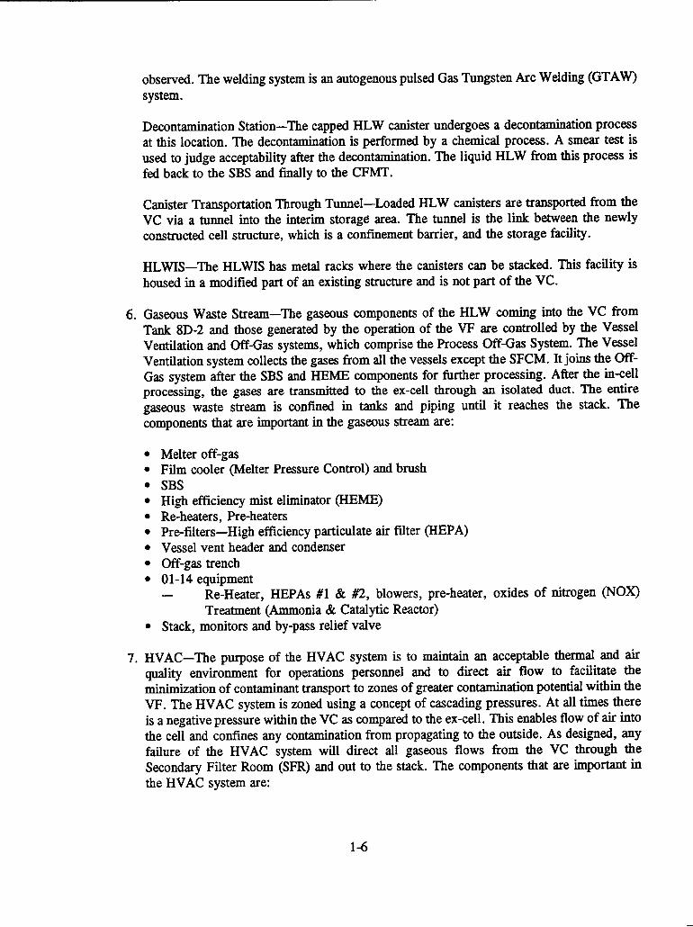
observed. The welding system is an autogenous pulsed Gas Tungsten Arc Welding (GTAW)system.
Decontamination Station-The capped HLW canister undergoes a decontamination processat this location. The decontamination is performed by a chemical process. A smear test isused to judge acceptability after the decontamination. The liquid HLW from this process isfed back to the SBS and finally to the CFMT.
Canister Transportation Through Tunnel-Loaded HLW canisters are transported from theVC via a tunnel into the interim storage area. The tunnel is the link between the newlyconstructed cell structure, which is a confinement barrier, and the storage facility.
HLWIS-The HLWIS has metal racks where the canisters can be stacked. This facility ishoused in a modified part of an existing structure and is not part of the VC.
6. Gaseous Waste Stream-The gaseous components of the HLW coming into the VC fromTank 8D-2 and those generated by the operation of the VF are controlled by the VesselVentilation and Off-Gas systems, which comprise the Process Off-Gas System. The VesselVentilation system collects the gases from all the vessels except the SFCM. It joins the Off-Gas system after the SBS and HEME components for further processing. After the in-cellprocessing, the gases are transmitted to the ex-cell through an isolated duct. The entiregaseous waste stream is confined in tanks and piping until it reaches the stack. Thecomponents that are important in the gaseous stream are:
* Melter off-gas* Film cooler (Melter Pressure Control) and brush* SBS* High efficiency mist eliminator (HEME)* Re-heaters, Pre-heaters* Pre-filters-High efficiency particulate air filter (HEPA)* Vessel vent header and condenser* Off-gas trench* 01-14 equipment
- Re-Heater, HEPAs #1 & #2, blowers, pre-heater, oxides of nitrogen (NOX)Treatment (Ammonia & Catalytic Reactor)
* Stack, monitors and by-pass relief valve
7. HVAC-The purpose of the HVAC system is to maintain an acceptable thermal and airquality environment for operations personnel and to direct air flow to facilitate theminimization of contaminant transport to zones of greater contamination potential within theVF. The HVAC system is zoned using a concept of cascading pressures. At all times thereis a negative pressure within the VC as compared to the ex-cell. This enables flow of air intothe cell and confines any contamination from propagating to the outside. As designed, anyfailure of the HVAC system will direct all gaseous flows from the VC through theSecondary Filter Room (SFR) and out to the stack. The components that are important inthe HVAC system are:
1-6

* Ventilation Zones, Concept of Cascading Pressures, Control In-Cell* Confinement-Doors and Windows, Infiltration* Prefilters-Dioctyl Phthalate (DOP) Testing, Seismic Qualification, Screens* In-Cell Coolers-Shared Cooling Tower Water (CW) with Ex-Cell Coolers* SFR* Flexible Connectors* Secondary HEPA Filters, Redundancy, Plenum Division* Stack-Monitors, By-pass Relief Valve* Control Room (CR), Operating Aisle Ventilation
8. Transfer Pits and Trench Ventilation-The transfer pits and trenches have thick concretestructures with drains that facilitate flow back into the waste tanks. The pits have single-walljumpers to direct flow of the waste. The ventilation system for the pits and trenches isindependent of that of the VF. The most important function of the ventilation is duringmaintenance operations. During the vitrification operations, the pit covers are in place, anda slightly negative pressure ensures backflow into the waste tanks.
1.4 OUTLINE OF SAFETY EVALUATION REPORT PRESENTATION
The presentation format in this report reflects a combination of NRC and DOE practices inpreparing SERs. Unlike SERs that have a formal role of accepting or rejecting the assessments in theSARs, this SER is intended to provide guidance to the DOE on radiological issues relating to the VP atWVDP. This approach is consistent with the NRC-DOE MOU.
The major part of the CNWRA review of the WVNS-SAR-003, Revision D, is presented inSection 2 of this report. In Subsection 2.1.1, the potential hazards at the site due to natural and human-caused events and the appropriateness of the choices are discussed. The VF design considerations andhow the various components are designed and analyzed are presented in Subsection 2.1.2. This subsectiondeals with the safe operations aspect of the VF. Evaluations of the designs of particular structures,systems, and components whose functions are important to radiological safety are contained in Subsection2.1.3. An assessment of the administrative features and their impact on safety is provided in Subsection2.1.4. Following the design evaluation, the management of waste generated in the vitrification campaignand the potential radiological doses during the plant operations are discussed (Subsections 2.2 and 2.3).Subsection 2.4 discusses the accident analysis presented in the WVNS-SAR-003, Revision D. Here, thecapacity of the various passive confinement barriers under conditions beyond design basis accidents(BDBAs) is addressed.
Section 3 discusses other safety considerations that affect design and operations not discussedin Section 2. Also, Section 3 summarizes the special studies and reviews conducted during the NRCreview process. Section 4 is a general presentation of interface issues that could arise from differentoperations or from nonradiological safety questions and that has a bearing on the overall radiologicalsafety at the VF.
Conclusions based on the overall evaluation and a few operational recommendations arepresented in Section 5. Results of independent evaluations performed by the NRC team on specifictechnical topics are incorporated into this document.
1-7

Dimensional units used in this SER are based on values taken from WVNS-SAR-003, tofacilitate reference to that document. As a result, no attempt was made to convert the units fromWVNS-SAR-003 to a consistent set of units for this SER.
References to site-specific operating procedures, QA documents, fire protection manuals, etc.(e.g., WVDP-106, WVNS-110, WV-984, TSD-A.3.6.B, WVNS-DC-046) are given in the appropriateSARs and are not reproduced in this SER.
1-8

2 SAFETY ANALYSIS REPORT AND SUPPORTINGDOCUMENTATION REVIEW
This section presents the detailed evaluation of the WVNS-SAR-003 and supporting documents conductedby the NRC and its subcontractor, the CNWRA. The various sections provide both the background onthe topics and their associated evaluations. Covered in these evaluations are hazard treatment, design anddesign philosophy, operational aspects, and accident analysis for the vitrification program. Thebackground information provided is brief, and the reader is referred to the WVNS-SAR-003 for additionaldetails.
2.1 ADEQUATE CONTROL OF HAZARDS
The hazards associated with the VF may occur during two major conditions including:
(i) Normal Operations'
(ii) Accidents
This discussion of the source of the hazards will follow the general process that the HLWundergoes in the VP. There are basically two types of radiological hazards associated with the VF.Radiological hazards are either confined (i.e., within process vessels and piping) or airborne. Shielding(passive confinement) is the major protective means of confined hazards, while ventilation (activeconfinement) is used to control doses from airborne materials.
At the beginning of the process (transfer of the waste from the tanks to the VC), the primaryconfinement is the waste transfer line. The waste transfer line is only used on approximately 7- to 8-dayintervals. The line is flushed with water after each transfer to eliminate most contamination, thussignificantly reducing the hazards. The concrete trenches containing the waste transfer lines constitute thesecondary confinement during this process.
Subsequently, the confined sources of HLW are largely located within the VC. The vesselscontaining the bulk of activity include the process vessels (CFMT, MFHT, and SFCM), the solid wastestream (turntable and filled HLW canisters), and the gaseous waste stream (SBS, HEMEs, and HEPAfilters), which includes entrained particulates. The process vessels provide the primary confinement whilethe VC provides the secondary confinement of the waste. All process vessels, piping, and associatedequipment are, in cases of maintenance or process upset, potential sources of airborne radioactivity. Toensure confinement of this airborne radioactivity, all areas having a potential for becoming contaminatedare ventilated in a controlled manner using the active confinement systems.
There are also confined and airborne sources of nonradiological hazards associated with coldchemical slurry preparation for vitrification and the VF ex-cell off-gas system, which are not discussedin this SER. The reader is referred to the WVNS-SAR-003 for details.
1 Refer to Section C.5.2.2.1.2 in WVNS-SAR-003
2-1
2.1.1 Identification of Hazards
Based on the guidelines given in UCRL-15910 (Kennedy et al., 1990), there are four basic stepsrequired in the identification of hazards for the facility. These steps provide a logical basis for thediscussion given in the SER. They include:
* The usage categories and performance goals for the VF have been established. The WestValley facility is considered a Moderate Hazard Facility (facilities where confinement ofcontents is necessary for public or employee protection). The performance goal for thefacility is an annual probability of exceedance of 10-4 or less, with respect to damage, tothe extent that the facility cannot perform its function. Additional information is containedin Section 2.1.2 of this document.
* For each category, the hazard probability was specified, and hazard loads were developed.This step includes the site selection and evaluation process. The major hazards consideredin the design of the West Valley facility are the seismic and tornado events. These events,in conjunction with the normal operating loads, provide the design basis for the facility.Details are presented in Section 2.1.2 of this document.
* For each category, design and evaluation procedures to evaluate facility response to hazardloads were utilized. Both basic structural adequacy and component functional adequacy wereaddressed. The major elements of the facility were designed using either equivalent static ordynamic linear elastic analysis techniques. General information on the design and evaluationprocedures are contained in Section 2.1.2 of this document. Details relating to specificsystems in the VF are contained in Section 2.1.3 of this document.
* For each category, criteria were applied to assess whether or not computed response wasacceptable. The primary concern in this review was radiological release. Therefore, thereview process includes both damage estimation and release fraction calculation[LA-10294-MS (Elder et al., 1986)]. Details relating to specific systems in the VF fornormal hazards are contained in Section 2.1.3 of this document. Details for accidentconditions are contained in Section 2.4 of this document.
The WVNS-SAR-003 was reviewed in relationship to these steps to ensure completeness of thesuite of hazards identified.
The complete set of hazards will be based, in part, on the loads used in the design of the VF.They are divided into three basic groups: (i) normal operating load conditions, (ii) severe environmentalload conditions, and (iii) extreme environmental load conditions. The normal operating load conditions,those loads that are encountered during normal plant operations and shutdown, are discussed below.
Dead Load (D)-Dead loads include the weight of structures and structural components, equipment,piping, walls, partitions, platforms, conduit, cable trays, and all other static gravity loads. Fluids or solidscontained within the equipment or piping are also considered a dead load (Dames & Moore, 1994a).
2-2

Live Load (L)-Live loads include floor and roof area loads, crane loads, layout loads due to temporaryplacement of movable equipment or structures, equipment handling loads, and vibratory and impact loadsfrom equipment and other processing loads (Dames & Moore, 1994a).
Thermal Load (To)-The VF structures were designed to withstand the thermal loads due to expansion,contraction, thermal gradients through structural shield walls, slabs, and beams, and thermalexpansion/contraction of structural steel framing members (Dames & Moore, 1994a). The outdoor designconditions are 78 'F (Summer) and 22 'F (Winter). Indoor design conditions vary with location andrange from 65 to 95 'F. For all thermal analysis, the as-built condition is assumed to be 65 'F (Dames& Moore, 1994a). For the High-Level Radioactive Waste Transfer System (HLWTS) piping, thetemperature of the fluid was conservatively taken as 220 'F (Dames & Moore, 1994b).
Internal Pressure (Po)-All the primary concrete structures in the VF have been designed to resist anegative pressure of 15.6 lb/ft2 (3 in. of water). This internal pressure loading is the result of the cellventilation system designed to maintain a pressure drop between the exterior and the interior of thebuilding (Dames & Moore, 1994a). For the HLWTS piping, the internal pressure is taken as 150 psig(Dames & Moore, 1994b).
Soil Pressure Load (%tatic, Hhydrostatic, HdynaC)-These loads include soil pressures exerted on thestructures by the backfill and the surcharge. Both static and dynamic soil load conditions are used (Dames& Moore, 1994a).
Differential Settlement (D)-An allowable differential settlement of 1/4 in. has been specified for designof the facility in the WVNS-SAR-001. Analysis has demonstrated that the differential settlement will benegligible (Dames & Moore, 1994a). For the concrete trenches in the HLWTS, the ultimate differentialtrench movement was 0.12 in. Since the piping was not installed in the trench for more than 2 yr afterthe trench was constructed, static differential displacements were not considered part of the analysis ofthe HLW transfer piping (Dames & Moore, 1994b).
Evaluation: The normal operational loads definedfor the VF are in conformance withstandard engineeringpractice [American National Standards Institute (ANSI)YAmericanSociety of Civil Engineers (ASCE) 7-88 and Uniform Building Code, UBC] asmodifiedfor site-specific and operational considerations. The specific influences of soilpressures and differential settlement have been adequately addressed.
The severe environmental load conditions are those loads that could infrequently be encounteredduring the plant life and are discussed below.
Snow Load (S)-Buildings and structures are designed for the following snow load conditions: 1,915 Pa(40 lb/fr2). The resulting loads are relatively small (ess than 10 percent of the dead load) compared toother design requirement loads. This load definition is the same as that given in Figure 7 of ANSI/ASCE7-88 (American National Standards Institute/American Society of Civil Engineers, 1988).
Wind Load (W)-Building structures and equipment on the exterior of the buildings are designed forwind loads with the following parameters.
* 100-year wind of 35.8 m/s (80 mph)
2-3

* Peak gusts of 43.4 m/s (97 mph)
* Based on ANSI A58.1 (American National Standards Institute, 1982) Exposure Condition C
The wind loads given are in agreement with the values given in Figure 1 of ANSI/ASCE 7-88(American National Standards Institute/American Society of Civil Engineers, 1988).
Evaluation: The severe environmental loads defined for the VF are in conformancewith standard engineering practice [ANSI/ASCE 7-88 (American National StandardsInstitute/American Society of Civil Engineers, 1988) and UBC InternationalConference of Building Officials, 1988] as modified for site-specific considerations.These loads are appropriately included in the margin of safety calculations.
The extreme environmental load conditions are those loads that are credible but highlyimprobable and include the following.
Lightning-The VF has lightning protection equipment/devices consistent with the requirements ofapplicable industrial standards.
Flooding-VF structures are located at elevations at least 14 ft above potential flood levels due to the100-yr storm and probable maximum precipitation (West Valley Nuclear Services Co., Inc., 1994a).
Seismic Load (EDBE)-Earthquakes are one of the extreme environmental conditions that form the criticaldesign basis events and control the safety margins for natural phenomenal hazards. These design basisevents meet or exceed DOE Order 6430.1A (U.S. Department of Energy, 1989) and UCRL-15910(Kennedy et al., 1990) guidance for natural phenomena. Site characteristics and analysis for naturalhazard phenomena are contained in sections of the WVNS-SAR-003 and are based on information inWVNS-SAR-001 and the accompanying Technical Support Documents (TSDs).
Tornado Load (Wt)-Tornadoes are one of the extreme environmental conditions that form the criticaldesign basis events and control the safety margins for natural phenomena hazards. These design basisevents meet or exceed DOE Order 6430.1A (U.S. Department of Energy, 1989) and UCRL-15910(Kennedy et al., 1990) guidance for natural phenomena. Site characteristics and analysis for naturalhazard phenomena are contained in sections of the WVNS-SAR-003 and are based on information inWVNS-SAR-001 and the accompanying TSDs.
Others-Other site-specific loads are enveloped by the loads above.
Evaluation: The extreme environmental loads defined for the VF are in conformancewith standard engineering practice [ANSI/ASCE 7-88 (American National StandardsInstitute/American Society of Civil Engineers, 1988), UBC International Conferenceof Building Officials, 1988), and NFPA (National Fire Protection Association, 1993),ANS-2.8-81 (American Nuclear Society, 1981)] as modified for site-specificconsiderations. For lightning, no specific review of the facility design was performedi. e., it is assumed that the statement the design is in accordance with the NFPA
requirements is correct). Details of the flooding conditions are contained in JSDs forWVNS-SAR-001 (7SD A.3.4-A, A.3.4-B, A.3.4-C). The seismic and tornado loads are
2-4

discussed in detail in subsequent sections. Based on an overview of the design of thefacility, the loads used in the design and analysis are complete.
2.1.1.1 Seismic Loads
The primary seismic hazards are ground motion and differential ground motion. The groundmotion can cause structural failure of buildings as well as failure of components within the buildings dueto either peak overload or dynamic responses. Differential ground motion can often lead to failure inunderground piping systems, especially where they enter "rigid' structures, as well as contact betweentwo adjacent structures. Additional hazards due to the seismic event may also include liquefaction, slopeinstability, and ground settlement.
As background for the discussion on the seismic loads, a historical perspective of the WestValley seismic design/evaluation is given based on presentations made by Dames & Moore at the reviewmeeting held in February 1995 (Rowland, 1995). The nuclear fuel reprocessing plant was initiallydesigned in accordance with the 1961 UBC Seismic Zone m requirements (International Conference ofBuilding Officials, 1961). Construction of the facility was accomplished between 1963 and 1966. In 1976,a plan was presented for relicensing of the fuel reprocessing facility. At this time, requirements for a safeshutdown earthquake (SSE) with a 0.2 peak ground acceleration (PGA), based on 10 CFR Part 100,Appendix A, were established by the NRC. This plan was eventually withdrawn.
Beginning in 1982 and continuing through 1995, several reassessments of the seismicdesign/evaluation criteria were made for the WVNS by Dames & Moore. In 1983, Dames & Moorecompleted a site-specific, probabilistic study that recommended a 0.07 PGA based on the 85 percenthazard curve (Dames & Moore, 1983). In 1987, the NRC accepted a 0.1 PGA for the Design BasisEarthquake (DBE) (comparable to the SSE) and suggested that margins should satisfy a 0.2 PGA eventwithout failure of confinement. The VF and supporting equipment were designed in accordance with0.1 PGA for horizontal motion and 0.067 PGA for vertical motion. A second probabilistic seismic hazardanalysis, based on Electric Power Research Institute (EPRI) procedures, was completed by Dames &Moore in 1992 (Dames & Moore, 1992). These two reviews provided the basis for the informationpresented in the TSDs for WVNS-SAR-001 (TSD A.3.6-A to A.3.6-I). A final study (Dames & Moore,1995) was completed in 1995. The 1995 analysis incorporated both EPRI (Electric Power ResearchInstitute, 1986; 1989) and Lawrence Livermore National Laboratories (LLNL) (Bernreuter et al., 1989;Sobel, 1993) probabilistic risk analysis for the eastern U.S. using procedures developed inDOE-STD-1024-92 (U.S. Department of Energy, 1992).
The seismic hazards at the WVDP site were also compared to those at the Ginna Nuclear PowerPlant (NPP), the closest NPP to the West Valley site. Based on information provided in the reviewmeeting (Rowland, 1995), Ginna was designed based on the following parameters. The facility waslicensed in 1968 based on a DBE with a 0.12 PGA using a deterministic analysis. In 1973, the sitingrequirements were set as: an SSE with a 0.20 PGA (6 x 10⁻⁵ annual probability) and an Operations BasedEarthquake (OBE) with a 0.08 PGA. The hazard risk analysis for this NPP was deterministic based onthe maximum credible event (Rowland, 1995).
From this historical background, it can be seen that the basis for definition of the seismicenvironment for the West Valley site has evolved over time. The original design was a deterministicassessment of the seismic event based on UBC requirements. The more recent assessment has been basedon a process hazard analysis (PHA) using the procedures established by EPRI and LLNL. These
2-5

probabilistic procedures form the bases for proposed changes to 10 CFR Part 100 and 10 CFR Part 50to allow for their use in the assessment of NPPs (Nuclear Regulatory Commission, 1994).
The basic requirements for seismic design for the VF comes from DOE Order 6430.1 (U.S.Department of Energy, 1983) which specifies that seismic resistance must be provided in critical facilitiesto withstand a DBE [LA-10294-MS (Elder et al., 1986) and references to DOE Order 6430.1 (U.S.Department of Energy, 1983)]. The DBE is also defined as an SSE. Because the DBE must be assumedto occur at any time, certain loads, such as common wind, snow, or intermittent maximum loading,should be added to earthquake loading.
The DBE has the following characteristics as defined in the WVNS-SAR-003:
* Annual probability of exceedance of 5.0 x o-4 based on a median hazard curve from asite-specific probabilistic analysis (Dames & Moore, 1983) (Figure 2-1)
* Horizontal-0. 1 PGA
* Vertical-0.067 PGA (defined as 2/3 of the vertical component)
* Design spectra in accordance with NRC Regulatory Guide (RG) 1.60 (NuclearRegulatory Commission, 1977a)
* Design structural damping in accordance with NRC RG 1.61 (Nuclear RegulatoryCommission, 1973)
It should be noted that the definition of the DBE was used as a basis for the design of the VFduring the 1982 to 1995 time frame (i.e., all new construction). Based on the 1987 suggestions by theNRC, for a margin of safety of greater than 2.0 XDBE (0.1 PGA), a re-evaluation of the seismic hazardwas done. The bases for the re-evaluation were updated information on the site characteristics andreduction of the conservatism in the analysis parameters. The methods used and the results of this re-evaluation follow.
The WVDP is located in a region of New York state characterized by relatively sparse seismicactivity. No historical earthquake of magnitude 6 or greater has occurred within about 200 miles (320km) of the WVDP site (Dames & Moore, 1995). Details of the site characteristics are given in TSDA.3.6-A (Regional and Site Geology), TSD A.3.6-B (Borehole Logs), and TSD A.3.6-C [TectonicProvinces of the Site Region (Revision A)] from WVNS-SAR-001.
Evaluation: No independent review of the local geologic and tectonic provinces wasperformed. Checks were made relating the resulting PGA levels to those of the GinnaNPP established by EPRI and LLNL. Based on a review of the 7SDs and thecomparison of PGAs, it is concluded that this information is correct.
The historical background has indicated that a number of approaches have been utilized to definethe seismic event. These approaches were based on the state-of-the-art procedures available at the time.The following discussion concentrates on the PHA since these levels were used in the evaluation of thesafety margins. Two separate approaches (LLNL and EPRI) are discussed, in addition to DOE proceduresto incorporate both into a common analysis. Each of these has established procedures for accomplishing
2-6

-84% Fractile Curve (+1 Standard Deviation)
Median CurveW 16% Fractile Curve (-1 Standard Deviation)L.)z
0wU1.00 10-4:z
10-w .5010 . . . . . . . .
E~~~~~~EK CEEAIN
-ligr2-.Fatlsesihaadcre (Dms&Moe193
2-7

the definition of the peak amplitude for the seismic level as given in ASCE 58-80 (American Society ofCivil Engineers, 1980).
The LLNL procedures for PHA are based on developments by two groups of experts coveringthe seismic-source and the ground-motion models. The S-expert panel consisted of 11 experts, each ofwhom developed a source model consisting of the location and earthquake recurrence rates for eachseismic source delineated. The information is related to the site geological and tectonic information givenin WVNS-SAR-001. The G-expert panel consisted of five experts, each of whom selected a set ofattenuation equations for use in the SHA. Combining the results of these two expert panels results in aseries of probability curves giving the PGA as a function of the annual probability of exceedance. Theoriginal LLNL results (Bernreuter et al., 1989) were later revised based on new recurrence rates andground-motion attenuation models and is presented in NUREG-1488 (Sobel, 1993). These studiesrepresent the entire eastern and central U.S., including NPPs near the WVDP site.
The EPRI procedures for PHA begin with development of seismic source models by the sixEPRI consultant teams. Again, these are related to the site geological and tectonic information given inWVNS-SAR-001. Three attenuation equations were used in the original EPRI SHA calculation for theeastern United States sites. These results were later updated with new attenuation curves. Combining theresults of the seismic source teams with the attenuation equations provides a probabilistic estimate of theseismic loads at a given site (Electric Power Research Institute, 1986; Electric Power Research Institute,1989).
New Eastern United States attenuation equations have been developed that should be consideredas replacements to some earlier equations. Furthermore, Dames & Moore (Dames & Moore, 1995) statethat it is acknowledged that the Nuttli attenuation equations (Bernreuter et al., 1989) are too conservativeand should be discarded from both the EPRI and LLNL methodologies. A similar comment applies tothe Triifunac/Gupta-Nuttli equations used in the original LLNL methodology (Bernreuter et al., 1985)."The use of an appropriate set of attenuation equations in the EPRI and LLNL methodologies wouldprobably not appreciably affect the PGA or short-period PSV estimates for WVDP, but their use wouldprobably result in lower response spectral values at periods around 1 second" (Dames & Moore, 1995).
The following discussion relates the application by Dames & Moore of these two proceduresto the West Valley site. It is taken directly from the executive summary of Dames & Moore (1995).
"The ground-motion hazard at the WVDP site was evaluated based on information inpublications by the EPRI and LLNL that pertain to seismic hazard analyses of NPPsites in the central and eastern United States. In particular, the data in thesepublications relevant to the seismic hazard at the Ginna NPP site were reviewed. TheGinna site is approximately 145 km NE of the WVDP and is the closest NPP toWVDP. Based on a review of the location of the seismic sources affecting the ground-motion hazard at the Ginna site, it was concluded that the bedrock ground-motionhazards at the Ginna and WVDP sites were similar. This conclusion was supportedby comparing the results of seismic hazard analyses at WVDP, conducted by Dames& Moore (1992) using the EPRI hazard analysis methodology, with the EPRI resultspublished for Ginna. The EPRI and LLNL results for Ginna were then combinedfollowing DOE Standard DOE-STD-1024-92. The resulting PGAs and 5% dampedpseudovelocity (PSV) response spectra were modified to account for the ground-motion amplification due to the local geology at the WVDP vitrification plant site.
2-8

The values of PGA at the 1 x 10⁻³ and 5 x 10⁻⁴ annual probabilities were 0.053 g and0.078 g, respectively. These values and the corresponding response spectra are belowthe WVDP DBE represented by the NRC 1.60 (Nuclear Regulatory Commission,1977a) design spectra normalized to a PGA of 0.10 g. Based on this result, a re-evaluation of the DBE for WVDP is not considered necessary (Dames & Moore,1995)."
Table 2-1 was developed by Dames & Moore to compare the results of the probabilistic SHAfor the West Valley site based on the EPRI procedures with the independent results for the Ginna NPP.The table gives the bedrock PGA levels for one probability level, 5 x 10⁻⁴, corresponding to the specifiedlevel for the DBE given in WVNS-SAR-003. This is the level recommended in DOE-STD-1020 forPerformance Category 3 (U.S.DOE, 1994). The results for both locations are similar. The meanprobability curves for both sites are given in Figure 2-2.
Table 2-1. Comparison of bedrock peak ground acceleration at a probability of5x 10 4 /yr (from Dames & Moore, 1995)
Level | EPRI WVDP _ EPRI Ginna LLNL Ginna_|
Median 0.055 g 0.045 g 0.035 g
Mean 0.075 g 0.053 g 0.073 g
Once the PGA level has beenestablished, it is necessary to develop the dampedresponse spectrum representative of the site.DOE-STD-1024-92 (U.S. Department of Energy,1992) recommends an approach to compute the5 percent damped response spectrum associatedwith the target probability level from the EPRIand LLNL SHA results. The approach is to firstcompute the geometric average of the medianPGA values for the EPRI and LLNL studies forthe target probability. These PGA values are thenmultiplied by a factor to convert to a mean value.This mean PGA value is the anchor accelerationfor a median spectral shape defined inNUREG/CR-0098 (Newmark and Hall, 1978) ora site-specific median spectral shape derived fromdeterministic methods (Dames & Moore, 1995).Table 2-2 compares the EPRI and LLNLprocedures for the Ginna NPP.
Table 2-2. Ginna Rock Site Medianpseudovelocity at 5x 1OI4yr probability(from Dames & Moore, 1995)
Frequency Hz IEPRI ILLL
1.0 0.88 cm/s 1.59 cm/s
2.5 1.26 cm/s 1.81 cm/s
5.0 1.28 cm/s 1.47 cm/s
10.0 1.00 cm/s 1.03 cm/s
25.0 0.47 cm/s 0.35 cm/s
l e 0.045 g 0.035 g
It was then necessary to adjust the bedrock values to account for the soil characteristics of thesite. The WVDP site is known to consist of shallow stiff soil over bedrock, and the potential amplificationof ground motion due to these soils exists (Dames & Moore, 1995). To account for the soilcharacteristics, the shallow soil factors from Toro and McGuire (1987), which increase with increasingperiod, were applied to the uniform probability ground motion values (Dames & Moore, 1995). The
2-9

10
10 _3
-o
lo
0~~~~~~~~~~~~~~~~~~~~~~~~~~~0-4\
0.0 0 0.05 0.10 0.15 0.20 0.25 0.300.PGA (g)
Figure 2-2. Electric Power Research Institute Methodology-West Valley Demonstration Projectversus Ginna mean probability curves (rock site) (Dames & Moore, 1995)
2-10

resulting spectra values are given in Table 2-3 and are shown in Figure 2-3. The important point to noteis that the design spectra for the DBE, RG 1.60 (NRC, 1977a), is significantly higher than the othervalues, DOE-STD-1024 (U.S.DOE, 1992) and uniform probability, throughout the majority of thefrequency range. This high design spectra for the DBE may result in a conservative estimate of the truemargins of safety.
Table 2-3. West Valley Demonstration Project soil site ground motion spectra (fromDames & Moore, 1995)
F Uniform Probability, | D
t~~~xO4y -- WVDP DBE
1.0 4.29 cm/s 15.7 cm/s 23.0 cm/s
2.5 4.48 cm/s 10.3 cm/s 19.5 cm/s
5.0 2.94 cm/s 5.16 cm/s 8.85 cm/s
10.0 1.67 cm/s 2.29 cm/s 3.77 cm/s
25.0 0.80 cm/s 0.56 cm/s 0.77 cm/s
00 0.078 g 0.078 g 0.10 g
Therefore, the PGA and the response spectra for the horizontal components of the seismic eventhave been established. Based on early information (American Society of Civil Engineers, 1980),indications were that the use of a vertical spectra equal to 2/3 of the horizontal spectra may not beappropriate for eastern United States earthquakes. More recent information (Electric Power ResearchInstitute, 1993; Atkinson, 1993; Boore and Atkinson, 1992; Gupta and McLaughlin, 1987; McGuire,1986) presented by Dames & Moore at the February 1995 meeting (Rowland, 1995) indicates that fora location distant from the source, typical of the West Valley site, the 2/3 value is appropriate.
Evaluation: The PGA level at the site is acceptable based, in part, on the conclusionsdrawn from the comment resolution meeting held at West Valley on February 14-17,1995, among the DOE and their contractors and NRC and CNWRA (Rowland, 1995).Comment resolution related to the seismic analyses for the WVDP is based onclarification of a number of issues including a definition of the design basis seismicevent.
The annual probability of exceedanceforDBEs as defined in WVNS-SAR-003 is basedon DOE-STD-1020 (U.S. Department of Energy, 1994), with an earthquake annualprobability of S x10-4. The DBEs, in general, conform to the definition of OBEs fornuclear reactor designs. The Beyond Design Basis Earthquakes (BDBEs) areconsistent with the definition of an SSE for reactor designs and have an annualprobability in the range of 1 X i-6.
Following the comments by both the NRC and DOE-EH-11 on the earlier versions ofthe seismic analyses, WVNS conducted extensive studies to evaluate regionalseismicity. They provided information at Ginna and the WVDP site based on two
2-11

0 .4 0 I I I I I I I I I I I I I I I
DBE (O.lg R.G. 1.60)Per DOE-Standard-1024
0.35 _....Uniform Probability
0.30
0.25
co 0.20
0.15 ".
I ..... -~~~~~~~~......
0.10
0.05
l l l l I l l l l I l l l l ~~ ~~~I I I I I I I I
0.000 II5 10 15 20 25 30 35
Frequency (cycles/sec)
Figure 2-3. Comparison of response spectra (Dames & Moore, 1995)
4-92
5% Damping
2-12

detailed studies by EPRI and LLNL. It was concluded that the earthquake hazard atWest Valley is similar to Ginna (Bedrock). Using this revised evaluation and currentguidance in DOE Standards 1020 (U.S. Department of Energy, 1994) and 1024 (U.S.Department of Energy, 1992), the evaluation basis earthquake is 0.078 PGA, whichis less than that used in the design of the facility (0.1 PGA). The values used in thedesign were determined to be conservative with respect to the probabilistic riskassessment.
WVNS computed the mean PGA from analyses based on the median PGAs obtainedfrom the EPRP and LLNL studies. WVDP site mean ground motion at SxlO-41/yr wasobtained using DOE-STD-1024 (U.S. Department ofEnergy, 1992). Initial calculationof the margin of safety was based on the probability of exceedance curves developedby Dames & Moore in 1983. If this margin of safety is less than 2.0 xDBE, updatedcurves were used and other conservative analysis procedures were taken into account.
Information provided by WVNS in TR-102293 (Electric Power Research Institute,1993) and published papers (Electric Power Research Institute, 1993; Atkinson, 1993;Boore and Atkinson, 1992; Gupta and McLaughlin, 1987; McGuire, 1986) indicatethat, unless directly on or adjacent to earthquake-generating faults, verticalcomponents of acceleration of two-thirds that of the horizontal acceleration areappropriate for eastern U.S. sites.
The required response spectrum for the seismic event used in the design is based onthat given in RG 1.60 (Nuclear Regulatory Commission, 1977a). Detailed analysis ofthe site-specific spectra indicates that the shape of the spectrum is conservative.
2.1.1.2 Tornado Loads and Tornado Missiles
The approach for determining wind pressures on buildings and other structures is consideredto be independent of the type of windstorm. For winds, the design must incorporate the effects ofpressure, total forces, atmospheric pressure change, and missiles.
The VC confinement structures are designed to withstand the forces of a Design Basis Tornado(DBT) having an annual return frequency of 1 x 10⁻⁶. Although the basic cell structures and ventilationsystem would continue to function, as required during and after occurrence of the DBT, the tornadocould, in theory, generate a missile capable of penetrating the shield windows that extend through the cellwall, thus jeopardizing the confinement integrity. Assuming that only 10 percent of the missiles wouldreach the cell confinement wall with full force, the area of glass with respect to the total wall area, andthe orientation of the missile, the frequency of a missile striking the window with sufficient force to causepenetration is 5 x 10⁻¹ 0 /yr.
Based on the information provided in the WVNS-SAR-003 (detailed analyses of tornadooccurrences in western New York State), the DBT characteristics are given below.
* Maximum wind speed 71.5 m/s (160 mph)* Rotation speed 49.2 m/s (110 mph)* Translation speed 22.35 m/s (50 mph)
2-13

* Radius of maximum rotational wind 45.7 m (150 ft)* Peak pressure differential 2.4 kPa (0.35 psi)* Rate of pressure drop 1.0 kPa/s (0.15 psi/s)* Annual probability of exceedance 1.Ox lo-6
The associated parameters for tornado-generated missiles include:
* Wooden plank 139 lb at 85 mph* Steel pipe 76 lb at 50 mph* Annual probability of exceedance 1.0 x 10⁻⁶
Evaluation: The parameters associated with the DBTand tornado-generated missilesare in conformance with standard engineering practice (McDonald, 1983; AmericanNuclear Society, 1983; Nuclear Regulatory Commission, 1974; 1977b) as modified forsite-specific conditions.
2.1.2 Design Features
Radiation protective features basic to the design of the VF are dedicated to maintaining radiationdoses to members of the general public and the work force as-low-as-is-reasonably-achievable (ALARA).Effective control of radiation doses depends primarily on design features that provide shielding from
sources of radiation: remote operations and maintenance; confinement of radioactive materials within theprocess vessels and piping; proper ventilation; effluent control; and monitoring and surveillance to verifydesign controls. Their physical design features, together with strict adherence to operational requirementspresented in WVDP-0101, provide effective radiation control.
There are two types of provisions to confine radioactive materials during normal and accidentconditions.
(i) Passive confinement barriers, including walls, hatches, roofs, doors, and shieldedviewing windows. The primary passive confinement structures are the reinforced concretevault structures that enclose the VC, Crane Maintenance Room (CMR), and TransferTunnel. These structures are designed to maintain their confinement during all credibleenvironmental load conditions. These barriers will be discussed in detail in Sections2.1.2.4 and 2.1.3.
(ii) Active confinement systems or components, including the blowers associated withmaintaining a negative pressure (relative to atmospheric pressures) in the VC. Thesesystems will be discussed in detail in Sections 2.1.2.5 and 2.1.3.
Evaluation: The passive/active confinement concept used in the design of the VF isin conformance with standard engineering practice. It conforms to the nuclear designstandards contained in 10 CFR Part 50, Appendix A, Criteria 2 and 16.
The basic loads used in the design of the VF were introduced in Section 2.1.1. During thedesign process it is necessary to combine these individual loads to account for concurrent application ofmultiple types of load conditions. Three groups of load combinations were used in the design of the VF.
2-14

(i) Normal operating load conditions (dead, live, thermal, internal pressure, and soilpressure)
(ii) Severe environmental load conditions (wind and snow) with normal operating loadconditions
(iii) Extreme environmental load conditions (tornado and earthquake) with normal operatingload conditions
Depending on the type of structure, the factors applied to each load in the load combinationprocess were in accordance with established engineering standards. The three basic type of structures andassociated load combinations included:
(i) Load combinations for concrete structures were established in accordance with AmericanConcrete Institute (ACI) 318 (American Concrete Institute, 1992) and ACI 349(American Concrete Institute, 1990)
(ii) Load combinations for steel construction established in accordance with the AmericanInstitute of Steel Construction (AISC) Steel Manuals (American Institute of SteelConstruction, 1989; 1991; 1992a)
(iii) Load combinations for piping established in accordance with American Society ofMechanical Engineers (ASME)/ANSI B31.3 (American Society of MechanicalEngineers/American National Standards Institute, 1987)
Refer to the WVNS-SAR-003 for specific values for each of these combinations. The"allowables" for each of the materials under the various loading conditions are also addressed and arein conformance with standard engineering practice.
Evaluation: The load combination procedures used in the design of the VF are inconformance with standard engineering practice [ACI 318 (American ConcreteInstitute, 1992); ACI 349 (American Concrete Institute, 1990); AISC 5327-84(American Institute of Steel Construction, 1984); AISC M016-89 (American Instituteof Steel Construction, 1989); AISCM015-91 (American Institute of Steel Construction,1991); AISC M017-92 (American Institute of Steel Construction, 1992a); AISCS341-92 (American Institute of Steel Construction, 1992b); ASME/ANSI B31.3(American Society of Mechanical Engineers/American National Standards Institute,1987); and ANSI/ASCE 7-88 (American National Standards Institute/American Societyof Civil Engineers, 1988)].
The VF includes basic structural systems, equipment, and components. Each of these hasdifferent design features. There are three categories of basic structures.
(i) Confinement barriers required to remain functional under site-specific design basisevents. The new engineered confinement barrier structures relied on during accidentscenarios, including natural phenomena induced accident scenarios, are as follows:
2-15

(1) VC(2) CMR(3) Transfer tunnel(4) SFR(5) HVAC CR(6) Diesel generator room (DGR)
For (1) to (6), the following are examined independently where applicable:RoofWallsCell doorsCell shield windowsCell hatchesCell pipe penetration seals
(7) HLWTS
(ii) Modified existing structures not required to remain functional under site-specific designbasis events. The facilities are primarily associated with the storage of the HLW in the
solid state. In this state, the potential for release is greatly reduced and, therefore, thedesign requirements are not as stringent. The modified existing structures include:
(1) EDR(2) Chemical process cell (CPC), which is now referred to as the HLWIS(3) CPC CMR(4) 01-14 Building, with the exception noted in (iii)
(iii) New structures not required to remain functional under site-specific design basis events.These are new structures that are not in the category of confinement barriers. In most
cases, these structures are designed in accordance with UBC requirements. The newgeneral construction includes:
(1) Sheet metal building surrounding the VC(2) CCB(3) Diesel fuel oil storage tank building(4) The off-gas pipe trench and new portions of 01-14 Building(5) Load-in/out area
Because of the multiple types of structures and the wide time frame under which they weredesigned and constructed, it is not possible to establish one design standard for all facilities. The reader
is referred to the WVNS-SAR-003 for specific information on the applicable standards for each system.
In addition, there are equipment, vessels, and components that have the potential of becoming
seismic hazards to the confinement barriers because of their shape, size, and/or mass. Identification of
the equipment and components is contained in C.5.2.6 of the WVNS-SAR-003. These are the major
vessels, equipment, and components within the VC that are designed to maintain structural integrity
during potential seismic events in order not to be challenges to the confinement barrier or threats to
adjacent components if they were not capable of surviving the seismic events. The design parameters arecontained in C.5.3 and C.5.4 of the WVNS-SAR-003.
2-16
Evaluation: The structures and equipment, vessels, and components of the VF havebeen properly identified. The appropriate design requirements have been identified andare in conformance with standard engineering practice (see Tables C.5.2.2.1.2-1,C.5.2.2.1.2-2, C.5.2.2.1.2-3, and C.5.2.2.1.2-4 in WVNS-SAR-003).
2.1.2.1 Design Philosophy
The WVDP design philosophy for control of radiation hazards can be generally characterizedas follows: (i) provide passive confinement of radiological releases under all conditions, including BeyondDesign Basis Events, which are also referred to in WVNS-SAR-003 as accident conditions; and (ii)provide for survivability of important structures, systems, and components under all design basis eventconditions (although functionality is not required under DBE or DBT conditions).
For normal operations, certain active confinement systems (e.g., off-gas processing system,HVAC, etc.) are required to function to maintain cumulative operating releases and doses below pertinentlimits. For all cases, multiple barriers are provided for confinement of sources of exposure toradioactivity. Standby power systems are available in case of loss of local electrical power.
WVDP has established Evaluation Guidelines (EGs) that define allowable radiation dose levelsfor both on-site and off-site cases. The dose levels also correlate with three ranges of event probabilities.The EGs are discussed in Section 2.4. In general, as the probability of the event becomes less, thecorresponding allowable radiation dose (which could result from the event) becomes greater.
The design of the facility is such that several redundant confinement barriers are used including:
(i) Storage canisters and processing containers, including piping, tanks, melter, etc., usedin passive confinement.
(ii) The building shell and auxiliary items such as the SS liner used in passive confinement.This includes the use of sufficiently air-tight physical boundaries to keep contaminationas close to the source as practical.
(iii) Ventilation system filtering and negative pressurization used in active confinement. Theobjective is to maintain pressure differentials between each confinement zone so that airflow travels from zones of lesser contamination potential to zones of greatercontamination potential.
An early WVDP design activity involved classification of structures, systems, and componentsinto safety class and quality levels. The WVDP Quality List aQ-List, X WVDP-204, is the "primary sourcefor establishing, identifying, revising, and maintaining an up-to-date listing of safety classes and qualitylevels' of facilities and systems under the QA Program.
From WVDP-204: Safety class and quality level classifications are based on design criteriadocuments, including WVNS-DC-022, Design Criteria, Vitrification of High-Level Waste. InWVNS-DC-022, the three primary design principles for confinement are (i) use sufficiently air-tightboundaries to keep contamination as close to the source as practical, (ii) use multiple barriers forconfinement, and (iii) maintain pressure differentials between confinement zones to promote air flow fromzones of lesser contamination potential toward zones of higher contamination potential. Other important
2-17

design criteria have been established for the WVDP for various structures and systems (WVNS-DC-046,Design Criteria, Sludge Mobilization Waste Removal System; WVNS-DC-048, Design Criteria, High-Level Waste Interim Storage System; and WVNS-DC-066, Design Criteria, Vitrification Load-In Facility).
A "graded approach" was used to assign quality levels based on increasing levels of qualitycontrol as the severity of potential consequences of hazards to safety, health, and environmental impactincreased. This system recognizes a gradation in importance of structures, systems, and components tosafety. The graded approach is used to demonstrate the meaningful selection of barriers to support thedefense-in-depth concept for various parts of the VF. However, there are no prescribed minimum numberof barriers that are needed under the graded approach. The WVNS-SAR-003 treats the ALARA issuesseparately from the graded approach. Many of the ALARA issues are approached from the overall siteoperations perspective and a design with a minimum dose opportunity for the operating or site personnel.The following is a summary of WVDP implementation of the graded approach in their assignment ofhazard classification, safety classification, and quality levels per procedures and criteria given inWVDP-204.
It should be noted that hazards other than radiological hazards were taken into account at WVDPfor safety class and quality level determination, but only radiological hazards classification is of concernfor this SER review.
During conceptual design, minimum safety and quality levels were assigned for each structure,
system, and major component by a group WVDP chose for their pertinent expertise. Also, redundancy,backup capability, testing, higher quality levels, and greater specification requirements were establishedto provide "defense-in-depth" for systems identified by the group as critical. Safety classification wasdesignated as Class A, B, C, or N. Generally, Safety Class A structures, systems, and components aredesigned using codes and standards applied at NPP and other nuclear facilities with a potential for verylarge releases of radioactive material. Safety Class B invokes codes and standards used in nuclear facilitieswith a potential for moderate releases of radioactivity. Pertinent codes and standards for Safety Class Care similar but less restrictive than for Safety Class B. Safety Class N codes and standards are commercialand manufacturers' standards. Thus, progressively more stringent codes and standards are applied fordesign, fabrication, installation, tests, and quality requirements to assure corresponding higher reliability.Criteria for safety classification are based on radiological off-site and on-site doses [(effective doseequivalent {EDE})] anticipated to result from potential failure, and they are given in Table 2 ofWVDP-204. Tabulated EDEs corresponding to safety classifications correlate to EDEs from the twofigures presented in Section 2.4 of this SER. If an item is required to limit radiation dose or otherhazards, the consequence of its failure is calculated by bounding analyses, allowance for uncertainties,and conservative assumptions. The highest safety class for any structure, system, or component at WVDPis Class B. Potential releases are limited by the batch process, which limits the maximum availableworking volume of HLW (that within VC process tanks) which is exposed to an energy source (melter)for dispersion. The HLW at the WVDP is stored in the liquid and sludge inventories in the Tank Farm.Once it is converted to molten glass, the HLW is in a more stable form and not as readily available fordispersion. The solidified and containerized glass is even more stable and is relatively immobile withrespect to release during storage.
The quality level specifies the level of review, application, and control of applicable criteriacommensurate with the safety classification and the necessary level of reliability for operations. The QAProgram, whose implementation is identified by the quality level, is based on ASME-NQA-1 (AmericanSociety of Mechanical Engineers, 1989). Quality level classification is based on the safety class, but also
2-18
includes service considerations such as operational impacts and cost (e.g., maintenance and replacementschedules and costs). Quality levels are also designated by A, B, C, and N. As a minimum, the qualitylevel must equal the safety class for any given structure, system, or component. The quality level,however, may be assigned a greater level than the corresponding safety class if justified by operationalimpacts and cost.
Table 2-4, which is taken from Table 3 of WVDP-204 (WVNS, 1994d), succinctly summarizessafety classes, quality levels, and corresponding codes and standards for structures, systems, andcomponents for WVDP. Attachment D to WVDP-204, "Q-List," identifies safety class and quality levelfor a detailed list of structures, systems, and components of the VF System. The table also identifiesvarious industry standards [e.g., ACI 318 (American Concrete Institute, 1992); AISC M016-89(American Institute of Steel Construction, 1989); etc.] which were chosen to apply to differentcomponents and structures for each safety class and quality level.
Mechanisms by which safety class and quality level are established for a particular item orcomponent of one of the systems in Table 2-4 are given in QM-2, Quality Assurance Program, andQM-3, Design Control.
The primary factor determining classification of structures, systems, and components is whetheror not they provide confinement. Confinement structures must withstand the effects of natural hazardsand confine the radioactive material to acceptable levels. Nonconfinement structures need not remainfunctional under the effects of natural hazards, but they should survive design basis events withoutcollapse and they must remain functional under less severe environmental loading.
For the systems within the scope of WVNS-SAR-003, earthquakes and tornadoes are theextreme environmental conditions that form the two critical design basis events and control the safetymargins for natural phenomenal hazards. Section 2.1.1 contains a discussion of these hazards. Forimportant structures, systems, and components, margins of safety have been computed to indicate thefactor which can be applied to the DBE or DBT loads before ultimate failure of the component willoccur. The definition provided for margin of safety in the WVNS-SAR-003, Draft D, was not completelyaccurate in that it defined the margin as "the factor by which loads produced by the DBE or DBT canbe increased before ultimate failure of the component will occur." The definition for margin of safetywould be more correctly stated as "the factor by which loads produced by the DBE or DBT can bemultiplied before ultimate failure of the component will occur." Correction of the definition wasrecognized, however, in the Review Comment Record (Mazzetti, 1994) response to comment 5-036, andit is expected that the definition will be corrected in future WVNS-SAR-003 drafts. Stresses due to loads(dead load, live load, etc.) other than those due to design basis events were accounted for in thecalculation of margin of safety, as shown in the example below for seismic loads.
M = [U-(D + PO + To)] / EDBE
where M = safety marginU = ultimate capacityD = dead loadPO = pressure loadT. = thermal loadEDBE = seismic load
2-19

Table 2-4. Safety classes, Q-levels, and codes and standards (from West Valley Nuclear Services Co., Inc., 1994d, Table 2.3of WVDP-204)
Facility Components
Control and _
Safety Quality Electrical Vessels/ lHeatClass Level Structures Systems Vents Pumps Valves Piping Exchangers
A A ACI 349; ASME IEEE Class 1E ASME Sec. III ASME Sec. III ASME Sec. III ASME Sec. Ill ASME Sec. III
Sec. Ill Division 1 Division 1 Division 1 Division 1 Division 1Division 1 TEMA "R" TEMA "R"Subsection NF
B B ACI 318 ISA Standards; ASME Sec. VIll ASME Sec. ANSI B16.5; ANSI B31.3 ASME Sec.NEC (designed to Division 1 Vill ANSI B31.3 VIllfail on preferred Division 1 Division 1mode) TEMA "R"
C C NYS Building ISA Standards; ASME Sec. VIll API-610 (or ANSI B16.5; ANSI B31.3 ASME Sec.
Code NEC Division 1 (or manufacturer's ANSI B31.3 VIllAPI 620 and standard) Division 1API 2000 for TEMA "C"large, low
pressure tanks)
N N NYS Building ISA Standards; Manufacturer's Manufacturer's Manufacturer's Manufacturer's Manufacturer'sCode NEC Standard Standard Standard Standard Standard
0t-j

Evaluation: The fundamental concepts of the approach to design for the WVDPrepresent sound engineering practice and are based on methodology used historicallyforfacilities with similar or greater hazards. The design philosophyfor the VF is onethat emphasizes the confinement ofpotential radiological releases. The outermost levelof confinement is provided by passive confinement structures and components whosecontinued function under all but incredible conditions is assured by design (10 CFRPart 50, Appendix A, Criteria 2 and 16). Multiple barriers of confinement areprovided to minimize dependence on any single barrier (10 CFR Part 50, CriteriaCategory II, Protection by Multiple Fission Product Barriers). Redundancy and/orbackup capability are included in the design for high reliability (10 CFR Part 50,Appendix A, Criterion 21). For ventilation of radiological areas, airflow is controlledso that airborne radiological contaminants are directed from areas of lessercontamination to areas of greater contamination. This 'cascading pressure ' designfeature has the effect of controlling doses due to airborne radiological materials[10 CFR Part 72, §72.126(a)].
The graded approach to assigning safety classification and quality levels haspreviously been found acceptable by NRC during the review of the site SAR. Thegraded approach originates from ASME NQA-1 (American Society of MechanicalEngineers, 1989), Basic Requirement 2. ASME NQA-1 is widely recognized as thebasic nuclear QA programs standard.
With respect to radiological hazards, limitation of Safety Class B to those componentsthatprovide primary confinement (e.g., concrete hot cell, transfer tunnel, VF shieldedviewing windows, etc.) and VC HVAC (e.g., duct-cell exhaust system, primary HEPAfilter bank, etc.) is consistent with the safety classification criteria given in Table 2of WVNS-204.
The choice of various industry standards that were chosen to apply to differentcomponents and structures for each safety class and quality level, as they appear inWVNS-204, appears to be appropriate and commensurate with the correspondingsafety class and quality level. The policies and guidance given in QM-2 appear to belogical and consistent with ASME-NQA-1 (American Society of Mechanical Engineers,1989). Procedures and guidance for design control in QM-3 reflect good designpractice and a degree of guidance adequate to control design quality.
The definition of the margin of safety should be changed in future revisions ofWVNS-SAR-003 to more accurately reflect the intent that it represents the factor bywhich the DBE or DBT loads can be multiplied before failure occurs.
2.1.2.2 Seismic Design Considerations
The seismic design considerations for the VF are based on the following statement given inUCRL-15910 (Kennedy et al., 1990). "Adequacy of critical and non-critical structures to withstandvibratory ground motion shall be verified, according to DOE Order 6430.1 (U.S. Department of Energy,1983), using suitable dynamic analysis techniques, except where the static response technique of the UBCcan be shown to provide a conservative estimation. The maximum loads determined by dynamic analysis
2-21
are then combined with dead load and other live load." An overview of the seismic analysis steps is givenin Figure 2-4 [from LA-210249-MS (Elder et al., 1986)1.
In the seismic re-evaluation, consideration was given to the overall response of the VF as wellas detailed calculations for specific equipment and components. The seismic design of the overall facilityis based on a soil-structure interaction analysis used to determine the global response of the facility(Gates, 1993; Raytheon, 1995). Excitation for these models was based on the time histories developedto envelope the site-specific response spectra. Results from this analysis were then used to developelevated response spectra, at specific locations in the VF, for subsequent analysis of specific equipmentand components. Samples of these analyses of specific-equipment and components were reviewed as partof the work performed under this program.
The seismic design of the overall facility is based on dynamic analysis of linear elasticsoil-structure models of the primary confinement cells. The initial analysis was based on a simplified 3Dbeam model of the structures with springs and dampers used to represent the soil characteristics (Gates1993). The beam elements and added mass were used to model the overall dynamic characteristics of thefacility. The damping values used in the original 3D stick model were 7 percent for the structuralelements and 20 percent for the soil to account for both material (hysteretic) and radiational (wavepropagation) damping. The value of damping used for the structural elements is consistent with thedamping values given in RG 1.61 (Nuclear Regulatory Commission, 1973) for reinforced concrete at theDBE level. A question that arose early in the review concerned the values used for soil damping in thesystem and the resulting composite damping. Initially, it was felt that 20 percent for soil damping wasexcessive because of the small strains that would be induced in the soil due to 0.10 PGA excitation.
To accurately define the strain field in the soil surrounding the foundation, it was necessary todevelop a full 3D solids model of the system including the soil and foundation structure (Raytheon,1995). The analysis used time-history motions for three simultaneous orthogonal directions to computethe earthquake response of the building structure. The time-history earthquake input motions to the modelwere synthetically generated to envelope the design basis response spectra in accordance with RG 1.60(Nuclear Regulatory Commission, 1977a). The damping properties of the model were based on RG 1.61(Nuclear Regulatory Commission, 1973). Spatial attenuation of energy from soil-structure interaction wasaccounted for in the model. Results of this type of soil-structure model were then used for subsequentsimplified analysis to verify the results (Rowland, 1995). The review process used by Dames & Mooreutilized a composite modal damping of 15 percent, based on the relative strain energy in the elements.
Evaluation: Based on the detailed soil-structure interaction analysis performed andinformation provided in the February 1995 meeting (Rowland, 1995), the values usedfor both soil and composite damping for the VF are acceptable. The soil-structureinteraction analysis of the overall response of the VF have been performed inaccordance with the state-of-the-art procedures.
The results of this overall dynamic analysis provided forces and floor motions at the variouslevels of the structure that were used in the design of the confinement structure (walls, roof, floors) andin the fundamental performance and anchorage requirements for equipment (primary filters, coolers,melter supports, etc.) within the structure designed for the induced loads resulting from the DBE. Thefloor-design, response-spectra method and the time-history methods were used in analysis of componentadequacy. A basic approach to these methods is discussed in RG 1.122 (Nuclear Regulatory Commission,1978a).
2-22
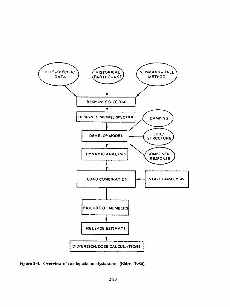
Figure 24. Overview of earthquake analysis steps (Elder, 1986)
2-23

A conservative approach to the seismic design is to perform a simplified equivalent staticanalysis based on the total weight of the structure and the peak acceleration of the DBE shock spectra.This procedure can be utilized for structures and equipment that have a first mode frequency greater thanthe cutoff frequency for the elevated portion of the response spectra. This corresponds to 33 Hz for thehorizontal RG 1.60 (Nuclear Regulatory Commission, 1977a) spectra.
The static procedure can also be applied to structures whose first mode is less than the cutofffrequency for the elevated portion of the response spectra. In this case, the equivalent static load for agiven mode is equal to the weight of the structure times a factor including the peak acceleration and anamplification factor, taking into account damping of the mode in question. For a single mode, thisequivalent static load is added directly to all other loads to determine the margin of safety. If multiplemodes exist, several different modal combination procedures can be applied.
For complex structures and equipment with modes within the elevated region of the responsespectra, it is advisable to perform a linear elastic finite element analysis (FEA). The structure orequipment is first modeled using finite elements to define the appropriate geometry mass, stiffness, anddamping characteristics. These models can range in complexity from detailed 3D solid models to simpler3D beam and truss models. For static analysis, after defining the structure, loading, and restraints, theresponse of the structure can be calculated. For dynamic analysis, an eigenvalue analysis is firstperformed to determine the natural frequencies and mode shapes. These results can then be used todetermine the dynamic response under a variety of loading conditions.
Dynamic analysis procedures for determination of the structural response of critical elementsto earthquake events can be based on a time-history solution or a response-spectra solution using modalsuperposition. The analysis for this program utilized a time-history solution based on a single set of threestatistically independent signals (two horizontal and one vertical directions). This excitation was appliedto FEA models of various critical structures and equipment.
There were several general concerns associated with the seismic analysis procedures utilized.A single set of three statistically independent time histories was used to calculate the dynamic responseof the system. This is appropriate when the assumption of linear elastic response is used, as was donefor the majority of the structures and components in the VF.
To further verify the validity of the input time histories, the duration of the strong motionportion of the event and the shape of the power spectral density (PSD) of the signal were shown to bein accordance with standard engineering practice. The duration of the strong motion portion of the eventwas related to the magnitude of the event [ASCE 4-86 (American Society of Civil Engineers, 1986)]. ThePSD of the signal was in accordance with the PSD for the RG 1.60 spectra (Nuclear Regulatory
Commission, 1977a).
Analyses show that all major process components in the VC pit have a seismic design capacitysufficient to prevent their ultimate failure or collapse from extreme environmental loading in excess ofthe DBE. Furthermore, the three tanks will not pound together causing them to lose their structuralintegrity. However, they may lose their functionality during a DBE. Continued operation of the VCHVAC system during and after a DBE event is expected because the HVAC CR, controls, blowers, filterunits, uninterruptible power supply (UPS), and associated standby diesel generator are DBE qualified.
2-24
Evaluation: The basic procedures used in the seismic analysis of the individualcomponents and equipment are in accordance with standard engineering practice.
It should be noted that FEA procedures are appropriate where the functionality of the structureor equipment can be defined in terms of the response motions and resulting stresses in the structure. Ifoperability is required, it is often easier to perform testing to verify functionality under the dynamicloading. The basic approach of the equipment qualification program is in accordance with establishedprocedures for NPP equipment, Institute of Electrical and Electronics Engineers, Inc. (IEEE)-344(Institute of Electrical and Electronics Engineers, Inc., 1987). Typically, a test program includessubjecting the equipment to time histories that envelope the required response spectra with a marginapplied, typically 10 percent, over the entire frequency range. The excitation is applied in threedirections, either three, two, or one axis at a time. The functionality of the equipment is checked before,during, and after the event, as required. If the equipment functions properly under all conditions, it isassumed to be qualified. A number of components were qualified by testing. No detailed review of thetest reports was done.
Evaluation: No CNWRAt review of any test results was performed.
Structures that are not required to confine radioactive or hazardous material have been designedto the New York State Code Manual for the State Building Construction Code, and incorporated seismicconsiderations from the UBC (International Conference of Building Officials, 1988). These structures arenot required to survive extreme environmental loads (natural hazard phenomena) without loss of function.However, these structures should survive without collapse to satisfy minimum life safety requirementsunder less severe environmental loading. These criteria apply to both new construction and modificationsto existing structures, per WVNS-SAR-003.
After design was completed, an independent assessment of the structural integrity of theconfinement barriers was performed by Dames & Moore. This assessment identified margins of safetyand modes of failure under extreme environmental loading beyond the DBE and DBT. Safety marginsreported represent the factor by which the loads produced by the DBE or DBT can be multiplied beforeultimate failure of the component will occur.
2.1.2.3 Tornado and Tornado Missiles Design Considerations
The structural response to wind loading as well as the penetration potential due to tornado-bornemissiles were considered in WVNS-SAR-003. Tornado resistance calculations consider combined loadsresulting from rotational plus translation wind speed, rate of pressure drop, and missiles. Wind loadingand pressure differential are of secondary concern for the major structural elements where other loadingscontrol, but are critical for the design of the HVAC system. Analysis of the response of the system totornado and the maximum wind loading was based on the procedures of ANSI/ASCE 7-88 (AmericanNational Standards Institute/American Society of Civil Engineers, 1988). Structural adequacy for thefacility with respect to the DBT is based on a design in accordance with an annual probability ofexceedance of 10-6 yr.
The penetration resistance of the primary structural elements was based principally oncomparison to published data for concrete, steel, and soil barriers. Some analysis of the doors wasperformed to consider rebound. The methodology for tornado missile load analysis on the special doorsis based on a two-step approach: (i) equivalent static, or (ii) dynamic response. Analysis done in support
2-25

of WVNS-SAR-003 used the equivalent static approach of testing to develop margins of safety (Gates,
1992). For the shield windows, the approach taken was to assume that penetration did occur and to
determine the level of leakage. If the leakage rate was below allowable levels, then the design was
considered to be acceptable. This procedure was discussed in detail in Section 4 of CNWRA 93-007
(Pomerening et al., 1993), to which the reader is referred for discussion of details associated with the
tornado and tornado missiles design considerations.
Evaluation: The basic design procedures for tornado and tornado missiles design
considerations used in support of WVNS-SAR-003 are in accordance with standardengineering practice [ANSI/ASCE 7-88 (American National StandardsInstitute/American Society of Civil Engineers, 1988)].
2.1.2.4 Passive Confinement Systems
Safety features have been engineered into the design of the VF to minimize the potential
environmental risks of the release of radioactivity due to loss of confinement. The safety features included
a system of confinement barriers that function both during normal vitrification operations and during
accident conditions or extreme environmental accident conditions. By definition, a confinement barrier
serves to restrain, but not necessarily totally contain, the contents within it. A structure required to
confine radioactive or hazardous material that could affect the health and safety of the public or site
personnel shall be designed to withstand the effects of natural hazards and still perform its safety
function(s) and confine the radioactive or hazardous material to acceptable levels.
A concept associated with the passive confinement systems in the VF is the use of multiple
confinement barriers and systems in support of the defense-in-depth aspects of the design of the VF.
Details of the multiple confinement barriers systems are given in the evaluation of specific structures,
systems, and components in Subsection 2.1.3.
The hazard and accident analysis given in Chapter 9 of WVNS-SAR-003 concludes that, during
accident conditions including natural phenomena-induced accident conditions, only passive confinement
barriers must maintain their integrity to provide an adequate level of confinement of the chemical and
radioactive materials being processed. These passive confinement barriers include the VC, crane
maintenance room, and transfer tunnel walls, floors, doors, roofs, shield windows, hatches, and
penetrations.
Releases to the environment can reasonably be expected to be very small, if not negligible,
during all accident conditions and especially during natural phenomena-induced accident conditions, due
to the fact that the SFR, HVAC CR, DGR, and the associated controls and equipment of these rooms are
designed to withstand extreme natural phenomena events.
Radiation protective features basic to the design of the VF are dedicated to maintaining radiation
doses to members of the general public and the work force ALARA. Effective control of radiation doses
depends primarily on the following design features that provide shielding from sources of radiation: (i)
remote operations and maintenance, (ii) confinement of radioactive materials within the process vessels
and piping, (iii) proper ventilation, (iv) effluent control, and (v) monitoring and surveillance to verify
design controls. These physical design features, together with strict adherence to operational requirements
presented in WVDP-0101, provide effective radiation control.
2-26
Evaluation: The use of passive confinement systems to mitigate the effects ofradiological releases during accident conditions is in conformance with standardengineering practice. Multiple barriers ofpassive components are also consistent withstandard engineering practice. It should be noted that during normal operation, activeconfinement systems are necessary to ensure that the cumulative effects of radiologicalreleases are below allowable levels.
2.1.2.5 Active Confinement Structures, Systems, and Components
Safety features have been engineered into the design of the VF to minimize the potentialenvironmental risks of the release of radioactivity due to loss of confinement. Systems required to confineradioactive or hazardous material that could affect the health and safety of the public or site personnelmust be designed to withstand the effects of normal operating and severe environmental conditions, stillperform its safety function(s), and confine the radioactive or hazardous material to acceptable levels. Itmust also be designed to withstand extreme environmental conditions without affecting the performanceof the passive confinement systems.
Details of the various active confinement systems or components are contained in Subsection2.1.3, especially 2.1.3.7 and 2.1.3.8.
Evaluation: The use of active confinement systems to mitigate the effects ofradiological releases during normal operation and severe environmental conditions isin conformance with standard engineering practice. The use of active confinementsystems during normal operation is necessary to ensure that the cumulative effects ofradiological releases are below allowable levels.
2.1.3 Evaluation of Specific Structures, Systems, and Components
This section contains an evaluation of specific structures, systems, and components, with respectto their compliance with the WVDP design philosophy, and their ability to withstand design basis eventssuch that radiation doses to the public and to operating personnel are adequately controlled. Margins ofsafety were obtained from WVNS-SAR-003. Information in this document is based on the most recentresults (Rowland, 1995) and may not be reflected in the WVNS-SAR-003 reviewed in this SER.
2.1.3.1 High-Level Waste Transfer System
The HLWTS described in WVNS-SAR-003 is limited to those components through which HLWis transferred from Tank 8D-2 to the VC confinement boundary. An overview of the HLWTS is shownin Figure 2-5. Components included are the Pump Pits 8Q-2, Diversion Pit 8Q-5, and the transfer trenchand its associated piping. The HLWTS covered by WVNS-SAR-003 does not include the tank farm,where existing tanks with HLW are located. Tank 8D-2, which is within the tank farm, is the origin ofthe waste stream. The Margin of Safety Summary for the HLWTS Confinement Barrier is in TableC.5.2.3-3 of WVNS-SAR-003, but this table also includes components, such as some associated with thetank farm.
The reinforced concrete transfer trench contains piping for transfer of liquid HLW to and fromthe waste tanks and the VC. Piping inside the trench is double-walled, welded SS, that is instrumented
2-27

Pipe Trench
Pit 80-1 \\
A|I'N> ~~~I N~s
8D-2 Vault IIand Tank /
Pit 80-5-
Pit 80-5 -
VitrificationBuilding
tJ)
00
II
8D-1 Vaultand Tank
/ LIEquipment
Shelter
//
Pit 80-4--
Vault
Figure 2-5. Overview of the high-level waste transfer system (Dames & Moore, 1994b)

between walls with conductivity-probe leak detectors. The double-walled piping provides confinement,while the reinforced concrete of the trench provides radiation shielding but not confinement. Piping runswithin the trench are supported with carbon steel supports such that a gradient in the line allows gravitydraining back to low points at Pits 8Q-2 and 8Q-5, from which any leakage gravity drains back to Tank8D-2.
The transfer pump, located in Pump Pit 8Q-2, discharges liquid HLW through a single-wall pipe(jumper) that transitions at the pump pit/transfer trench wall into the double-walled SS piping typical ofthe transfer trench. Potential leaks from the jumper drain back to Pump Pit 8Q-2 and then back to the8D-2 tank below. Each pump pit is lined with SS for secondary containment of potential leaks, and anysuch leakage is drained back to the tank below. Conductivity probes are installed in the pits to detectleaks, and the associated alarm is routed to the Plant Ventilation System (PVS) Building where the pumpoperators are stationed. Pump operators respond to the alarm by shutting down pump operations. Leakdetectors (conductivity probes) in the double-walled transfer pipe are instrumented to electronic interlocksthat prevent pump operation and HLW transfer if a leak is detected. The volume of liquid HLWtransferred in a batch to the CFMT (3,400 gal.) is preset via the pump controller, which automaticallyshuts down the pump when that volume has been transferred. Transfer lines are flushed between batchesto prevent solids buildup.
The PHA (Table C.9.3-1 of WVNS-SAR-003) indicates that operability of leak detectors inpump pits and the transfer trench is to be verified, but the text of WVNS-SAR-003 does not discuss whenor how this is to be accomplished.
The portion of the HLW transfer trench nearest the VB is covered with steel trench coversinstead of the concrete trench covers that are used for the rest of the trench. WVNS-SAR-003 does notaddress any difference in hazards or maintenance procedures for the steel-covered section. Note that noindependent review of the shielding requirements of any elements was performed. Dames & Moore(1994a) indicates that inside the VF, the trench is covered with steel plates to provide radiation protectionto workers in the operating aisles of the VF.
Valves within the Diversion Pit 8Q-5 are operated through sealed holes through the concretecover so that HLW can be routed from Tanks 8D-2 to the CFMT, and out-of-specification waste solutionscan be returned from the VC to the tank farm. Return lines from the waste header and condensate returnlines drain by gravity and are hard-piped (not valved) through an adjacent chamber of Pit 8Q-5.
Ventilation for the pump and diversion pits is provided by the waste tank farm ventilationsystem (WTFVS). No ventilation was provided for the HLW Transfer Trench, and this was rationalizedin WVNS-SAR-003 by noting that process liquids are transferred through double-walled piping that drainsto the floor of one of the pits.
Pump Pits 8Q-1 (over the 8D-1 tank) and 8Q-4 (over the 8D4 tank) are not adequatelydiscussed in the WVNS-SAR-003, and neither are the in-ground pipes for transfer between these tanksand the vitrification system. Future revisions to WVNS-SAR-003 should indicate which DOE-approvedsafety documentation covers these pits and transfer pipes.
2-29
Margin of Safety
The margin of safety against the DBE for the HLW reinforced concrete trench is given in TableC.5.2.3-3 of WVNS-SAR-003 as greater than 7 xDBE. The margin of safety for the double-walled steel
piping is greater than 4 xDBE, while that of the pipe support within the trench is greater than 2 xDBE.
Single-walled SS jumpers within the pits have a margin of safety greater than 3 xDBE, per Table
C.5.2.3-3 of the WVNS-SAR-003. The margin of safety for the connecting PUREX couplers is listed inthe table as greater than 1 xDBE, which is the lowest of the margins listed. Potential failure is mitigatedby the SS liner of the pit, from which any leak would gravity-drain to one of the HLW tanks.
The margin of safety against rupture due to the DBE for the buried double-walled SS pipe isgiven in Table C.5.2.3-3 of WVNS-SAR-003 as greater than 1.OxDBE although Dames & Moore
(1994b) indicates the margin to be greater than 4.0 xDBE, based on the seismic re-evaluation. These are
gravity flow return lines for materials from the VF, acidic waste header material, and condensate fromthe CFMT. They have a heavy concrete slab on top for radiation shielding and tornado missile impactprotection.
The margin of safety for HLWTS components listed in Table C.5.2.3-3 against the DBT is not
less than 7 xDBT, based on penetration by a tornado-driven missile. The margin against the DBT for the
steel-covered portion of the trench adjacent to the VB is not listed in the table.
Defense-in-Depth, As-Low-as-is-Reasonably-Achievable
HLWTS design features that provide multiple levels of confinement include the following: (i)double-walled piping inside the trench, (ii) SS lining for each pump pit for secondary containment of
potential leaks; and (iii) gravity-drain from pump pits to HLW tanks. Elements of the design that reflectthe application of the concept of ALARA include installation of conductivity probes between walls of the
double-walled SS transfer pipe, electronic interlocks that prevent pump operation and HLW transfer ifa leak is detected between the two walls of the transfer pipe, the installation of conductivity probes for
leak detection in the pump pits and the diversion pit, automatic control of batch volume transferred from
Tank 8D-2 to the CFMT, and the incorporation of gradients in various transfer lines to allow gravity
draining back to low points. The associated alarm is routed to the PVS Building where the pumpoperators are stationed.
Evaluation: The population of structures, systems, and components considered in theWVNS-SAR-003 for the HLW7S includes most of those that are important to active andpassive confinement. Missing from the WVNS-SAR-003 are discussions on the safetyaspects of (i) Pump Pits 8Q-1 and 8Q4; (ii) the buried double-walled steel pipe fromthose two pits; (iii) the steel-covered portion of the HLW pipe trench, and (iv) testsforfunctionality of leak detection in pump pits and those in the transfer trench. Futurerevisions of WVNS-SAR-003 should either provide such discussions or refer the readerto them elsewhere. The scenarios considered in analysis of margins of safety for thestructures, systems, and components of the ILWWS are appropriate and complete. Themargins of safety for the structures, systems, and components of the HLWWS indicatethat none should fail under design basis loads. For those passive HLW7S componentsmost important to confinement (pump pits and diversion pit, pipe trench), margins ofsafety are not less than 2 except for the PUREX couplers, from which leaks gravitydrain back to tanks. There is some variation between certain margins of safety given
2-30

in WVNS-SAR4003, Dames & Moore (1994a), and Dames & Moore (1994b). Noindication of the reason for the differences is given in WVNS-SAR-003, and it isassumed that the values resultingfrom seismic re-evaluation (Dames & Moore, 1994b)are most up to date. Analysis of the HLW73 is based on the soil-structure interactionanalysis (Raytheon, 1995) and independent Dames & Moore calculations (Dames &Moore, 1994a; 1994b) and is in conformance with standard engineering practice.
2.1.3.2 Cold Chemical System
Description
The cold chemical system (CCS) includes several tanks and pumps that are used in the mixingand transportation of the various chemicals and glass formers needed for the VP. The CCS is housed ina building 10.4 m wide and 17.2 m long. The building and its contents are not part of the passive oractive confinement structure of the VF. As such, they are not required to be functional during anyextreme natural hazards. The building houses nine tanks: three slurry tanks, one drain tank, and fiveprocess tanks. The CCB is a nonradiological area, and the main concern is the potential for chemicalcontamination. The CCB HVAC system is used mainly to maintain a suitable thermal and an adequateairflow environment for the personnel. The building HVAC system maintains a slight negative pressurewith respect to the outside. However, the CCB CR has a slight positive pressure. The HVAC system inthe CCB is independent of the VC HVAC. The potential for dusts and vapors in the CCB is present inthe scale room area. A dust collection hood with an air filtration system in the scale room minimizes thechemical contamination in the area. Chemical spills in the building are collected by the cold chemicalsump and stored in the cold chemical drain tank for future off-site disposal. A complete summary of thePHA for the CCS is given in Table C.9.3-5 of the WVNS-SAR-003. None of the indicated hazards areradiological in nature.
Margin of Safety
The CCS components are not part of the confinement system for the VF, and specific marginsagainst design basis seismic events were not calculated. However, all the process and drain tanks, andthe associated piping structures, are designed and fabricated in accordance with ASME Boiler/PressureVessel Code Section VIII, Division I, that provides the acceptable operational margins of safety.
Defense-in-Depth, As-Low-as-is-Reasonably-Achievable
There are no special considerations in the CCS required to mitigate any radiological releasessince radiological hazards are not present.
Evaluation: The controlfor the operation of the tanks in the Cold Chemical Facilityis separate from the controlfor the VC. The operations are sometimes unmanned andunsupervised in the CCB. An alarm system and a control panel to switch on equipmentand valves exists in the building. Also, an alarm sounds in the VC CR from the CCB,if the alarm from the CCB is unattended. However, there are no controls in the VCCR to implement any action, and the possibility exists for unplanned transfers or shut-offs of cold chemicals to the VC. It is recommended that the possibility of thissituation be addressed as part of the operational readiness review.
2-31

2.1.3.3 Confinement Structures
Description
The primary confinement structures for the VF consist of reinforced concrete structures. Some
are new construction while others are modifications to existing structures. The major elements aredescribed briefly in the following. These barriers have various integral enclosures and components,including special doors, shield windows, pipe penetrations, hatches, trench covers, etc. These componentshave been engineered to maintain their integrity as confinement barriers. Where possible, redundancy ofbarriers has been incorporated in the design so that radiological releases to the environment would requirethe failure of more than one barrier. Refer to WVNS-SAR-003 and supporting documentation for detailsof the design and construction of the facility. The engineered confinement barrier structures relied onduring accident scenarios, including natural phenomena-induced accident scenarios, are described in thefollowing sections.
Vitrification Cell
The VP of converting the liquid HLW to a glass form is carried out in the VC. The VC is theprimary passive confinement system for the HLW during the VP. It is a reinforced concrete structure andincludes special doors, shield windows, pipe penetrations, etc. The overall dimensions of the VC areapproximately 38 ft (E-W direction) by 64 ft (N-S direction), as taken from plan drawings inWVNS-SAR-003. The major portion of the floor is at an elevation of 100 ft and the cell has a ceilingheight of approximately 145 ft. At the north end of the cell is a pit that contains the three major processtanks and melter. The pit extends 26 ft in the N-S direction and has a floor at elevation 86 ft. Othersections of the VC contain facilities for handling the canisters (including the canister turntable, weldstation, and decontamination station), HVAC systems, off-gas systems, and process control andmonitoring systems. The thickness of the reinforced concrete structures varies throughout the cell and isa nominal 3 ft. The walls of the VC are covered with a SS liner up to an elevation of 122 ft. This lineracts as a barrier to any liquids that may spill. The remainder of the reinforced concrete cell is paintedwith a special paint for radiation control and decontamination. Careful attention was paid to the design
of the special doors, shield windows, pipe penetrations, and other penetrations to ensure they would notcompromise the confinement barrier. There are two viewing windows on the north wall and three viewingwindows on the east wall of the VC. There is a hatch on the roof of the VC to allow installation of
components and maintenance as required. Equipment and components installed in the VC are discussedin detail in the following sections of this document. Refer to the WVNS-SAR-003 and supportingdocumentation for details on the design and construction of the VC. The PHA for the VC is containedin Table C.9.3.3-2 of WVNS-SAR-003, and it includes both airborne and contained radiological hazards.The identified hazards also consider the potential for fire.
Crane Maintenance Room
The CMR is located on the south end of the VC aligned with the east wall. The CMR isincluded as part of the confinement structure because it communicates with the VC environment duringcrane maintenance. The CMR is located above the transfer tunnel and is utilized for maintenance of thecranes used within the VC. The overall dimensions of the CMR are approximately 38 ft (E-W direction)by 36 ft (N-S direction), as taken from plan drawings in WVNS-SAR-003. The floor is at an elevationof 124 ft and the ceiling is at approximately 145 ft. Special Door #2 allows access between the CMR andthe VC. This door moves vertically during opening into a reinforced concrete pocket located above the
2-32

CMR. It should be noted that during normal operation this door will remain closed, providing someisolation between the CMR and VC. Door # 7 allows access to the CMR from outside the confinementbarrier. There is a hatch cover on the room of the CMR to allow for installation of and access to thecranes.
Transfer Tunnel
The transfer tunnel is included as part of the confinement structure because it communicateswith the VC environment during transfer of canisters to storage. The canisters are transferred throughthe tunnel with a transfer cart capable of holding four canisters. The VC and transfer tunnel were builtto mate with the existing EDR and CPC (now called HLWIS). For this reason, the transfer tunnel isdesigned and built to be seismically "decoupled" from the EDR and HLWIS. The transfer tunnel islocated directly below the CMR and is approximately 19 ft (E-W direction) by 36 ft (N-S direction) astaken from plan drawings in WVNS-SAR-003. The floor is at an elevation of 100 ft and the ceiling isat approximately 124 ft. The transfer tunnel Door #1 allows access between the VC and the EDR. Thisdoor moves horizontally into a reinforced concrete pocket on the east side of the facility. As previouslynoted, during normal operation this door will remain closed, providing some isolation between thetransfer tunnel and the VC. Door #8 is used for access between the transfer tunnel and the HLWIS. ThePHA for the transfer tunnel is contained in Table C.9.3.3-3. For confinement consideration, one failurescenario is related to failure of the shield doors.
Secondary Filter Room
The SFR is necessary to maintain the cell air filtration function for active confinement. VC airis drawn into the SFR through two 24-in.-diameter ducts in the south wall of the VC. The air is thenfurther processed prior to release to the atmosphere. The SFR is located west of the transfer tunnel alongthe south wall of the VC. The SFR is an L-shaped structure within a rectangular structure that isapproximately 41 ft (E-W direction) by 36 ft (N-S direction), as taken from plan drawings inWVNS-SAR-003. The floor is at an elevation of 100 ft, and the ceiling is at approximately 124 ft. SpecialDoor #6 allows access between the SFR and the EDR. Special Door #4 allows access to the SFR fromoutside the confinement barrier.
Diesel Generator Room
The DGR is designed to withstand natural phenomena events so that backup electrical powerwould be available to run the active HVAC confinement system components. It contains the backup dieselgenerator and associated controls. The DGR is located in the northwest corner of the rectangular structurethat contains the SFR. The DGR is approximately 17 ft (E-W direction) by 18 ft (N-S direction) as takenfrom plan drawings in WVNS-SAR-003. Access to the DGR is through a door into the SFR.
HVAC Control Room
The HVAC CR is necessary to maintain the cell air filtration function and contains theequipment and controls necessary to operate the VC HVAC. The HVAC CR is located above the DGRand SFR and is accessed from outside confinement through Special Door #5. The HVAC CR isapproximately 24 ft (E-W direction) by 36 ft (N-S direction) as taken from plan drawings inWVNS-SAR-003.
2-33
Equipment Decontamination Room
The EDR is an existing structure that was modified to accommodate functions of the VP.Structures such as the EDR are not required to withstand the DBE, since their failure would not resultin significant environmental releases. Separation between the EDR and the new VC construction is a 3-in.seismic joint containing Rodofoam II. The EDR is approximately 49 ft (E-W direction) by 39 ft (N-Sdirection) as taken from plan drawings in WVNS-SAR-003.
High-Level Waste Interim Storage
The HLWIS is an existing structure (CPC) that was modified to accommodate functions of theVP. Structures such as the HLWIS are not required to withstand the DBE, since their failure would notresult in significant environmental releases. The major portion of the HLWIS is approximately 22 ft (E-Wdirection) by 93 ft (N-S direction) as taken from plan drawings in WVNS-SAR-003. There is anadditional short section that interfaces to the EDR. The PHA for the HLWIS is given in Table C.9.3.3-4,and it includes failure due to damage to the reinforced concrete structures.
Analysis of the confinement structure response included the roof, walls, mat, soil, special doors,hatch, and shield windows. For the roof, walls, and mat, the majority of analysis was based on strengthof materials approach under the various loading conditions. Response of the soil was addressed in thesoil-structure interaction analysis. The structural design review and integrity assessment of the eightspecial doors of the VF that function as critical elements of the primary confinement barrier system werepart of the Dames & Moore review. Three separate methods of investigation were used to assess thestructural integrity of the shield doors under extreme environmental conditions. These methods includedanalytical methods, experimental methods, and engineering judgment. A comprehensive list of failuremodes for the doors was developed (Gates, 1992). Operability and/or leak prevention is not a requirementfor the special doors, only that they remain in place. For the hatches, uplift was the primary concern.The primary concern for the shield windows was penetration during the tornado events.
Margin of Safety
Analysis of the primary confinement structure response included the roof, walls, mat, soil,special doors, hatch, and shield windows. Results of the margins assessment for the primary civilstructures are:
* Roof, Margin > 3.5 xDBE
* 26-inch wall, Margin > 4.5 xDBE
* 48-inch wall, Margin > 3.5 xDBE
* Mat foundation, Margin > 6.5 xDBE
* Foundation soil, Margin > 8.7 XDBE
The failure mode for the cell roof and walls is yield of the reinforcing steel, resulting in aplastic hinge. Indications are that cracking of the roof slab and the top portion of the walls of the VFcould occur during an earthquake of magnitude less than the DBE, when out-of-plane bending is
2-34
combined with thermal stresses. The assumption made in WVNS-SAR-003 was that cracking is notconsidered a failure because there will be no potential for release of radiological materials since crackingwill not propagate through the thickness of the structure (Dames & Moore, 1994c). For the foundationmat, the failure mode was uplift, while the soils failure was based on cracking. The major structuralelements, including the roof, wall, and mat, have margins of safety greater than 3.5 xDBE. This is notthe controlling factor for design of these structures, which is the combined dead and thermal loading.
Evaluation: A review of the fundamentalfrequencies of the civil structures, providedby Dames & Moore, indicate the lowest mode for the reinforced concrete vault is 7.0Hz for one of the lateral directions and represents rigid body motion of the structure.Therefore the analysis techniques used to develop the margins of safety areappropriate. Each of these margins of safety are acceptable based on the assumedloading, damping, and analysis procedures. Reasonable assumptions have been usedin calculating the consequences of tornado missiles striking the windows. Theconclusion that there will be no releases resulting from the missiles is acceptablebased on the evaluation that the missiles do not directly penetrate any of the in-celltanks or piping containing HLW.
In addition to structural failure, the potential for contact between the VF cell and the EDR ofthe existing Nuclear Fuel Reprocessing Plant was calculated. The separation between the VF and the EDRduring the seismic events is based on modeling the response of the building under the influence oftraveling seismic waves combined with the dynamic response of the buildings. This analysis showed amaximum of 0.7 in. closure for a total gap of 3 in. for an uncoupled model with 15 percent compositedamping. For a coupled model, the maximum closure was 0.8 in. The resulting margins of safety areacceptable. Analysis on the influence of the dynamic characteristics of the Rodofoam was performed andfound to be insignificant.
Evaluation: The analysis techniques used to develop the margins of safety are inconformance with standard engineering practice. The margins of safety are acceptablebased on the assumed loading and damping. Contact between the two structures is notcredible.
The behavior of the existing 160-ft reprocessing plant ventilation stack was analyzed underextreme environmental loads that include wind, tornado, and earthquake. The intent of the study was torealistically assess the collapse potential of the stack and the risk that such collapse might pose to the VF.Even if this failure were to occur, the possibility of any damage to the VF is remote.
Evaluation: The existing stack does not appear to pose any problem to theconfinement barriers.
The combined earthquake and dead load demand on the doors and their support hardware wasbased on using the peak response for the spectra provided in WVNS-EQ-264 and an equivalent staticanalysis. The critical margins of safety for the doors are:
* Transfer Tunnel Door #1, Margin > 2.1 xDBE
* CMR Shield Door #2, Margin > 2.5 xDBE
2-35

* CMR Personnel Door #7, Margin > 4.0 xDBE
* Transfer Tunnel Door #8, Margin > 2.7 xDBE
For these shield doors, the lowest frequencies are 5.2 Hz (Door #2 in the N-S direction) and
6.1 Hz (Door #8 in the N-S direction). All other frequencies are greater than 33 Hz, so the equivalent
static methods used to assess the margins of safety are appropriate. In all cases, the peak responseacceleration of the required response spectrum was used in the analysis, which is a conservative approach.
The special doors on the exterior of the facility must also be designed to resist tornado events
but only need to stop tornado missiles and remain in place. The lowest margin of safety associated with
the special doors is greater than 1.0 xDBE based on yielding of the door leafs on Doors #4 and #5.
Evaluation: The special doors have margins of safety associated with both the
earthquake and tornado events that are acceptable. Consideration of the appropriatefailure modes have been included in the analysis.
The major consideration of the windows was penetration as a result of tornado-generatedmissiles. The worst case is the impact of the leaded glass windows with a 3-in.-diameter steel pipe
traveling at 50 mph. For the shield windows, it appears that there is limited detailed test or analysis datafor the response of such thick windows to missile impact. Details of the penetration analysis are contained
in CNWRA 93-007. For the shield windows, the amount of leakage through the most credible hole was
found to be acceptable by Dames & Moore (Gates et al., 1989). The margin of safety associated with the
earthquake event was greater than 3.0 x DBE.
Evaluation: The windows have margins of safety associated with both the earthquake
and tornado events that are acceptable. Consideration of the appropriate failuremodes have been included in the analysis.
The primary concern for the hatches on the VC and the CMR roof are uplift during the seismic
events. The margin of safety for the cell roof hatch is greater than 6.0 xDBE, while the margin of safety
for the CMR roof hatch is greater than 10.0 XDBE.
Evaluation: The hatches have margins of safety for the earthquake design basis event
that are acceptable. Consideration of the appropriate failure modes have beenincluded in the analysis.
Penetration failure was considered for relative motion of various portions of the penetrations
as well as the potential for shearing due to impact of other structure and components. It should be noted
that the majority of penetrations are designed with shut-off valves and other passive systems that will
reduce the amount of release to acceptable levels. The lowest margin of safety for the five penetrationsconsidered was greater than 2.5 xDBE.
Evaluation: The penetrations have margins of safety for the earthquake design basis
event that are acceptable. Consideration of the appropriate failure modes have beenincluded in the analysis.
2-36

Defense-in-Depth, As-Low-as-is-Reasonably-Achievable
The defense in depth concepts for the confinement systems are the use of multiple barriers andactive/passive systems. For contained HLW, the first barrier is the process vessels and piping for theliquid phase and the canisters for the solid waste phase. If failure of the process vessels occurs, the liquidwill be confined within the process pit of the VC. It will be confined by the SS liner and the reinforcedconcrete structures. Consideration of failure during the solid stage is considered insignificant because thewaste is in a state that will not allow for release above allowable levels.
For potential releases associated with airborne contamination, the defense in depth is associatedwith the passive and active confinement systems. The passive systems are the confinement structuresdiscussed in this section. The active systems are discussed in other sections of this document.
2.1.3.4 Concentrator Feed Make-up Tank, Melter Feed Hold Tank, Submerged Bed Scrubber
Description
The CFMT controls the feed make-up that is eventually sent to the SFCM via the MFHT. TheCFMT is fed by the HLW from Tank 8D-2 and the effluent from the SBS. This mixture is sampled andanalyzed to check for the proper concentration needed for the melter slurry. The cold chemicals and glassformers prepared in the CCS are also added in the CFMT. The PHA for these vessels is contained inTable C.9.3-2 of WVNS-SAR-003.
Margin of Safety
The three process tanks, namely CFMT, MFHT, and SBS are within the VC and are designedto withstand UBC Seismic Zone 3 forces. These tanks also carry an inventory of liquids. The UBC staticanalysis methodology does not adequately provide for the interactions among the liquid inventory, tankstructure, and the tank support system. A subsequent dynamic analysis conducted by WVNS's contractor,Dames & Moore, provided a more detailed evaluation of the margins for failure for the tank and supportstructures. The new calculations show margins greater than 1.7 against ultimate failure or collapse of thetanks for a DBE (Rowland, 1995). It is expected that the structural integrity will be maintained for thetanks for DBE. However, the functionality may be lost for loads greater than the DBE where largedisplacements may sever connecting lines. The weakest component of the three tanks is the supportsystem. A common support for the three tanks has a margin of safety of greater than 1.4xDBE. Thesupport structure is made of A36 carbon steel I-beams. While both the CFMT and the SBS areconstrained from movement in all directions, the MFHT allows for vertical uplift. For the MFHT, anonlinear analysis was performed to account for large displacements during uplift of the tank. All otheranalyses were linear elastic analyses.
Defense-in-Depth, As-Low-as-is-Reasonably-Achievable
The three tanks are located in a SS-lined pit within the VC. This pit provides additionalprotection against spillage and leaks. The drains can collect any contaminated fluids and assist in theconfinement of the source of contamination. Also, the structural design of the tanks is such that, for DBEconditions, the tank components do not dislodge and affect any confinement barrier.
2-37

Evaluation: The detailed dynamic analysis conducted by WVNS for the three tanksand the support structure is appropriate and conforms to engineering practice. Thelowest modes for the tanks are within the elevated portion of the design spectra, sothe dynamic analysis is appropriate. The lowest margin calculated for the processtanks is greater than 1.4 xDBE. Note that this margin is based on information givenin the February 1995 meeting (Rowland, 1995) rather than in WVNS-SAR-003. Thisis acceptable because these are not part of the passive confinement system, andmargins greater than 1.0OxDBE are acceptable for the active confinement system.
2.1.3.5 Slurry-Fed Ceramic Melter
Description
The SFCM is key to the VP. The SFCM dries and melts the slurry feed from the MFHT andforms glass. In the melter, three Inconel 690 electrodes are operated in a controlled fashion to maintainuniform heating. The feed rate to the SFCM is in the range of 20 to 150 L/hr. The feed is made up ofthe HLW slurry, and glass formers (boron, silicon, and modifiers) are added as oxides or hydroxides.A cold cap, a solid crust, is maintained on top of the molten glass in the SFCM to provide the initialheat-up of a new batch of feed to begin drying it. As the cold cap heats the feed, gaseous and vaporcomponents such as H20 and NO2 are formed. Gaseous components are handled by the process off-gassystem. The cavity in the SFCM is made of a corrosion-resistant refractory while the shell is made of acorrosion-resistant Inconel material. Temperature in the melter ranges from 1,100 0C to 1,225 0C. Themolten glass exits the main cavity into an overflow chamber at an average flow rate of 25 to 45 kg/hrand is then transferred to the HLW canisters for cooling. The PHA for the SFCM is contained in TableC.9.3-2 of WVNS-SAR-003.
Margin of Safety
The SFCM is supported by a steel truss frame at a height of 100.5 ft in the VC pit and isdesigned for possible removal in service. The SFCM is constrained from movement in all directions afterallowing for thermal expansion and contractions. There are specially designed restraints necessary toensure the structural integrity of the melter. From a detailed finite element dynamic analysis, the marginof safety was shown to be greater than 2.1 xDBE. The melter itself is a very rigid structure when thebrick lining and internal refractories are considered with the Inconel shell.
Defense-in-Depth, As-Low-as-is-Reasonably-Achievable
The design and operation of the SFCM generally supports the defense-in-depth concepts. Theinventory in the SFCM at any time is controlled. The development of a cold cap limits hydrogenexplosion possibilities. The electrode selection and operations maintain uniform and controlled melttemperatures. The molten glass exiting the SFCM is controlled by an air-lift arrangement. This systemprevents accidental spillage on the floor of the cell. The off-gases generated during the process aretrapped and sent to the SBS in a closed loop arrangement.
Evaluation: The design and analysis of the SFCM and its support system areconsistent with standard engineering practice. Because of the special supports, thelowest mode is 126 Hz, above the frequency in the response spectrum where theresponse acceleration is significantly amplified. The feed constituent controls and the
2-38
potential chemical reactions were developed during the Functional and CheckoutTesting of Systems (FACMS) runs using nonradiologicalfeeds. However, the basis ofthe various chemical processes in the melter have not been verified. Also, there areno data developed with radiological feeds. The balance between the amount of oxidantand reductant in the system is important to the quality of glass and the compositionof the off-gases produced. It is recommended that a plan be outlined to develop thefeed reduction index for the radioactive feedfrom data generated in the early part ofthe vitrification operations.
2.1.3.6 Solid Waste Stream Components
After the HLW has been converted into a solid form, the hazards associated with regard toradiological releases and potential radiation doses are significantly less. Likewise, hazards associated withthe operation of components which process the solid waste form and potential accidents involving thosecomponents are greatly diminished. See Tables C.9.3-2, C.9.3-4, and C.5.2.6-1 of WVNS-SAR-003. Thesolid waste stream components of the VP include the following: (i) turntable, (ii) weld station, (iii)decontamination station, (iv) canister transfer cart, and (v) HLWIS. Following are discussions ofradiological safety aspects associated with each of these solid waste stream components.
Turntable
Description
The turntable is the device that holds the canister during filling with molten glass and retainsthe canisters filled with solidified glass wasteform until they are cool enough for further processing (toa centerline temperature of approximately 550 'C). Since cooling from the approximate 1,150 'C pourtemperature is a lengthy process, two stations in the turntable are allowed for canister cooling afterpouring. One station is available for moving a cooled full canister out of the turntable and replacing itwith an empty canister. The turntable rotates to move the next unfilled canister into position for filling.The turntable precisely locates the canister beneath one of the two pour spouts of the melter as it is beingfilled. Three independent means are available to determine proper alignment: (i) shield window viewingof alignment marks, (ii) closed-circuit TV viewing of alignment marks, and (iii) load cell platformcentering. The station at which the canister is positioned as it is being filled is located under the pourspout of the melter. An electronic interlock prevents turntable rotation when there is air flow to themolten glass airlift so the canister does not move while pouring is in progress. Ventilation from the off-gas system is used to remove potential contaminants from the air between the pour spout and the canister.
Three techniques are available to determine when the 80 percent canister fill goal has beenreached during pouring: (i) a load cell, (ii) an infrared level detection system (ILDS), and (iii) massbalance calculations. Two of these three must be in agreement for airlift operations and pouring from themelter to continue. Overfilling of canisters is not a significant concern, since greater than 8 hr arerequired to fill from 80 percent to 100 percent. After filling, canisters are removed either to the canisterweld station or to temporary storage at the canister storage rack.
Canisters are placed into and removed from the turntable with the remotely operated cell craneand canister grapple. In case of malfunction, the turntable drive components are remotely replaceable withthe cell crane.
2-39

Margin of Safety
In-cell components, including the turntable, have been reviewed for structural and anchorageintegrity. The in-cell, off-gas framework was analyzed against seismic loading for yielding of thestationary frame, pounding against the melter support frame, and failure of the turntable support. Nofailure was predicted from analysis for seismic events with margins of safety greater than 2.3 xDBE. Thisvalue, given in the February 1995 meeting (Rowland, 1995), is slightly greater than the 2.1 margin givenin Table C.5.2.6-2 of WVNS-SAR-003. No credible failure scenario exists for the turntable with respectto tornado loading.
Defense-in-Depth, As-Low-as-is-Reasonably-Achievable
The turntable is designed for remote maintenance and replacement. Hazards associated with theturntable are relatively small. Three independent means are available to determine proper canister locationbefore melt pour. Multiple technologies and associated components are used to prevent overfilling ofcanisters, which is the most likely accident associated with the turntable.
Evaluation: This design complies with the concept of cascading pressures for controlof the flow of contaminated air by controlling airborne contaminants during the pourprocess by using the low pressure in the off-gas system to direct contamination towardfiltration. In addition, multiple barriers of confinement exist since the turntable lieswithin another confinement barrier, the SS-linedfloor of the VC. Defense-in-depth isincorporated in the design by two means. Multiple technologies are used to preventoverfilling canisters and any associated spills, and three independent means areavailable to indicate the level to which the canister has been filled. The length of timerequired to fill from 80 percent to 100 percent (greater than 8 hr) mitigates thepotential for overfilling. The structural design analysis is in conformance withaccepted engineering standards. The lowest modes of the system are 6.1 and 7.7Hz,within the amplified region of the response spectrum. Therefore, the dynamic analysisperformed is appropriate.
Canister Weld Station
Description
After transportation by the cell crane to the canister weld station, a small sample of the glassshards at the top of the canister is removed. One out of every ten of the canisters will be tested for glassquality at this time, and samples from all canisters will be archived. Filled canisters are fitted with lids,that are remotely welded. The weld process is visually observed with remote cameras and directlyobserved through the shield windows, and weld process parameters are monitored to confirm weldquality. If a bad weld is detected, three weld repair procedures are available, including one in which asecond lid is installed over the first.
The solid waste form within the canisters at the time of handling at the weld station limitspotential radiological hazards. The greatest hazard at the weld station exists during handling of thecanister-during transportation to and from the Weld Station with the cell crane. The canisters aredesigned not to fail as a result of a 7-m drop on an unyielding surface. Accident analyses presented inSection 9.4.6 of the WVNS-SAR-003 indicate that the airborne fraction from a canister drop, before or
2-40
after filling, would result in extremely small on-site or off-site doses. If HVAC filtration is not availableduring such an accident, resultant total effective dose equivalents (TEDEs) are still well within EGs.
Canisters are handled by the cell crane with a grapple attachment that lifts the canister by itsupper flange. Canisters are stored in an eight-place Canister Storage Rack after welding, with the optionof also storing canisters there before welding. If uncapped canisters are stored in the storage rack, theyare fitted with a temporary lid to keep extraneous material from entering the canister.
All in-cell canister weld equipment can be repaired remotely, and exposure of electrical andelectronic equipment to radiation has been limited to prevent damage and to facilitate maintenance.
The weld station is anchored to the VF reinforced concrete floor with epoxy anchor bolts whosemargin against seismic failure is greater than 4xDBE. Resistance to the 95 'F ambient operatingtemperature and radiation field near the welder was discussed and resolved during the February 1995meeting at West Valley (Rowland, 1995).
Margin of Safety
The canister weld station has been designed for structural integrity and anchorage under UBCSeismic Zone 3 forces with an importance factor of 1.5. The margin of safety was estimated to be greaterthan 1.8xDBE in Table C.5.2.6-2 of WVNS-SAR-003, using engineering judgment, although morerecent information indicates that this margin of safety is based on a re-evaluation performed by Dames& Moore (Rowland, 1995). Equipment other than passive confinement needs only to satisfy a margin ofsafety greater than 1. OxDBE.
For the in-cell canister storage rack, the lowest margin of safety from Table C.5.2.6-2 is 1.5for buckling of a main transverse brace of the frame. The margin for support failure and pounding againstthe turntable is greater than 3 xDBE.
No credible failure scenario exists for the weld station or canister storage rack with respect totornado loading.
Defense-in-Depth, As-Low-as-is-Reasonably-Achievable
This design incorporates multiple barriers of confinement. The weld station lies within anotherconfinement barrier, the SS-lined floor of the VC. Airborne contamination from a canister drop isconfined by the HVAC system. Two methods are available for monitoring weld quality, and multiplerepair procedures are available if a bad weld is detected.
Evaluation: Seismic integrity for both the weld station and the canister storage rackappear to be acceptable for the potential hazards that exist there. Independentdynamic analysis for these systems was performed by Dames & Moore and resultedin lowest modes within the amplified region of the response spectra. Therefore,dynamic analysis is appropriate. The Dames & Moore reference (1994d) indicates thatno independent review of the weld station was performed, although the informationprovided by Dames & Moore in the February 1995 meeting (Rowland, 1995) indicatesdifferently. For monitoring weld integrity, no mention is made in the WVNS-SAR-003of consideration of the use of other available technologies such as ultrasonic testing
241

and x-ray examination for quality control of weldments. Future revisions of theWVNS-SAR-003 would benefit by offering a rationale for not adopting suchtechnology. Multiple available weld procedures provide defense-in-depth for the weldprocess.
Canister Decontamination Station
Description
The canister decontamination station is designed to remove external contamination from the
canister after welding. Such contamination is anticipated to be difficult to remove (described in
WVNS-SAR-003 as "baked on"). Decontamination is accomplished by a "chemical milling" process,
whereby powerful acids etch a small depth of surface (0.0002 in.) from the canister. The decontaminationsolution consists of 5 percent dilute nitric acid and ceric (Ce+4 ) nitrate. The process is limited in depth
of surface removal by available quantity of ceric ion (Ce+4), the reactant, and control of temperature andtime in the decontamination solution.
The canister is positioned within the decontamination tank, the bolted tank lid is secured, and
the decontamination solution is gravity-fed into the tank. During the 6-h residence time within the heated
(65 'C) tank, sparger air agitates the solution. After the decontamination period, the solution is reducedwith hydrogen peroxide to reduce the Ce+4 to Ce+3 and make it nonreactive. The decontamination
solution is transferred to a neutralization tank, from which it is transferred, in turn, to the SBS and to
the CFMT. A second, flushing batch of dilute nitric acid is used during normal operations to
decontaminate the canister. For every 65 hr of operation (the approximate time allowed for filling a singlecanister), two nitric acid batches are expected to be prepared.
The CCS provides decontamination and flushing solutions that are used during decontaminationof canisters. Such solutions include demineralized water, dilute nitric acid, dilute sodium hydroxide, mild
detergent solution, dilute oxalic acid, dilute potassium permanganate, and dilute potassium dichromate.Pumps and lines are flushed between transfers to prevent unwanted chemical mixing or residence timeswhich could be detrimental to equipment life.
If smear samples remotely taken from the canister after decontamination indicate it is necessary,
the canister can be decontaminated a second time. After decontamination is complete, canisters can be
either transferred to the canister storage rack or to the transfer cart for transport to the HLWIS.
Margin of Safety
The canister decontamination station has been designed for structural integrity and anchorage
under UBC Seismic Zone 3 forces with an importance factor of 1.5. The margin of safety was estimated
to be greater than 1.9 xDBE in Table C.5.2.6-2 of WVNS-SAR-003, using engineering judgment.
No credible failure scenario exists for the canister decontamination station with respect totornado loading.
2-42
Defense-in-Depth, As-Low-as-is-Reasonably-Achievable
This design incorporates multiple barriers of confinement. The Decontamination Station lieswithin another confinement barrier-the SS-lined floor of the VC.
Evaluation: Seismic integrityfor the decontamination station appears to be acceptablefor the potential hazards that exist there. This is based on the conservatism inherentin the UBC requirement and the independent assessment performed by Dames &Moore. WVNS-SAR-003 does not adequately discuss the effects on the quality of melterfeed for vitrification of recycling the decontamination solution after neutralization.Future revisions of the WVNS-SAR-003 would benefit by adding such information.
Canister Transfer Cart
Description
Canisters are transferred through the transfer tunnel and EDR to the HLWIS by the canistertransfer cart. The cart can transport four canisters at a time. It receives canisters from either the weldstation or the storage rack, as canisters are handled with the grapple and cell crane. The motorized carttravels on rails from the VC, through the EDR, and into the HLWIS. The cart is radio-controlled andpowered by batteries, with four completely independent drive trains. The PHA is given in Table C.9.3-3.
Margin of Safety
The canister transfer cart has a margin of safety against seismic loading greater than 1.8 XDBE.This value appears in Table C.5.2.6-2 of WVNS-SAR-003 where engineering judgment is listed as thebasis of assessment. A mitigating factor is the limited time (0.4 percent of the vitrification campaign)during which the canister transfer cart is in operation. In the information on the fundamental frequencyprovided by Dames & Moore at the February 1995 meeting (Rowland, 1995), the margin of safety isgiven as greater than 1.0 xDBE.
No credible failure scenario exists for the canister transfer cart with respect to tornado loading.
Defense-in-Depth, As-Low-as-is-Reasonably-Achievable
This design incorporates multiple barriers of confinement since all cart transfers occur withinareas served by HVAC systems.
Evaluation: Seismic integrity for the canister transfer cart appears to be acceptablefor the potential hazards that exist there. The design and analysis are in accordancewith standard engineering practice. Also, the reduced time during which canisters aremoved with the cart reduces the probability of occurrence below that for the seismicDBE.
2-43

High-Level Waste Interim Storage
Description
The HLWIS facility is designed to store the solidified HLW in 270 to 300 decontaminatedcanisters until they can be shipped to a federal repository. The cell floor and walls of the HLWIS arelined with SS up to a height of 0.46 m, and interior concrete surfaces are coated with a radiation-resistantpaint. HLWIS dimensions are 28.3 m long, 6.7 m wide, and 13 m high. Reinforced concrete walls are1.8 m thick. During vitrification, primary access to the HLWIS is through a tunnel to the EDR. Thetunnel is shielded with a concrete-filled shield door, 3.4 m wide, 1.2 m thick, and 4.3 m high, whichmoves horizontally.
Operations within the HLWIS are aided by the ability to view directly through four shieldedwindows that use lead glass filled with mineral oil. Closed-circuit TV cameras are also used.
The HLWIS facility is an existing structure that was referred to as the CPC during its prior usefor spent-fuel recycling. The crane serving the HLWIS is referred to as the CPC crane, and it can beisolated from the HLWIS for maintenance in the CPC crane room. The CPC crane room can be accessedthrough a vertical lift 0.9-m-thick shield door.
The HLWIS facility is protected against airborne contamination by HVAC ventilation (mainplant/head end ventilation system) which is reviewed in Section 2.1.3.8 of this SER.
The HLWIS facility is also designed to store failed equipment after removal from the VC. Glassshards removed from canisters for archiving samples are also stored in the HLWIS.
Two accidents were considered for the HLWIS in WVNS-SAR-003: Failure of the HLWIS roofand crane fall, neither of which can occur at DBE levels of seismic activity. Both on-site and off-sitedoses resulting from these incredible events remain within EGs.
Margin of Safety
No credible failure scenario exists for the weld station or canister storage rack with respect totornado loading.
Defense-in-Depth, As-Low-as-is-Reasonably-Achievable
The HVAC filtration prevents contamination from exiting the HLWIS. The solid waste formwithin the HLWIS minimizes potential releases during accidents. The HLWIS structure incorporatesanother confinement barrier, the SS-lined floor.
Evaluation: Structural analysis for the HLWIS was not performed as part of themargin study for the WVNS-SAR-003. However, analyses performed by both the LosAlamos National Laboratory (LANL) and LLAE indicate that lateral piles for thebuilding foundation can withstand seismic loads in excess of 1 xDBE. Theconsequence offailure of the storage facility will not produce any significant release,since the HLW stored in the HLWIS is already in a solid form.
2-44

2.13.7 Gaseous Waste Stream-Process Off-Gas System
Description
The process off-gas system is one of three distinct ventilation systems that provide activeconfinement. The other two confinement ventilation systems are discussed later in this SER. They are (i)the VB HVAC system, that also services the VC; and the (ii) HLWIS and EDR Ventilation, that utilizesthe existing main plant and head end ventilation systems.
The process off-gas system at WVDP provides control of contamination and removal ofradioactive particulates to reduce their concentration within acceptable limits before release to theatmosphere. The off-gas system is used to maintain a slight vacuum on the melter and process vesselsso that off-gases will be directed through equipment which removes radioactive particulates. This preventsoff-gas from entering the surrounding air such as the ambient air in the VC, and it concurrently preventsthe contamination that such releases may cause.
Although the off-gas systems are described in various places in the WVNS-SAR-003, a briefdescription is provided here for clarity. For further detail, refer to the WVNS-SAR-003, particularlySections C.4.5.3.2, C.5.2.6.10, C.5.2.7.4, C.5.5.4, C.6.2.3, C.6.3, C.7.4.1, C.9.4.3, C.9.4.7.1, andC.9.4.9.
The process off-gas system controls and conditions melter off-gas and process vessel off-gas ina system whereby the two flows are combined [see Figure 2-6 (taken from Figure 6.3.1-2 ofWVNS-SAR-003)]. Table 6.3.1-1 of the WVNS-SAR-003 summarizes off-gas system design data and isreproduced as Table 2-5. The off-gas from the melter passes through the film cooler, the SBS, and a misteliminator before being combined with the noncondensible off-gases from the CFMT and the MFHT. Thefilm cooler incorporates an automated, replaceable corrosion-resistant brush to periodically remove anysolids that may accumulate in the off-gas at the melter. The film cooler and the SBS cool the SFCM off-gas from 300-400 'C to 60 'C. The SBS is a passive device that bubbles off-gas through water in a bedof ceramic spheres. Excess liquid from the SBS is recycled back to the CFMT. The combined flow isthen conditioned both within the VC and subsequently in the 01-14 Building before being released throughthe 60-m main plant stack. Within the VC, the combined flow passes through a HEME preheater (toavoid condensate forming on the HEPA filters), and two HEPA filters in series. Each of thesecomponents is provided with redundancy for backup. The in-cell HEPA filters are referred to as prefilterssince they cannot be DOP tested in place. The off-gas exiting the prefilters is reheated in a post-heaterand transferred to the 01-14 Building in an insulated duct in the off-gas trench.
The flow from the vessel vent header system will be heavily laden with evaporated moisture,and this water is removed by the vent header condenser before subsequent joining with the flow from theSFCM off-gas. The condensate from the vessel vent header condenser is returned to Tank 8D-3 forsubsequent processing. The vessel vent header can also accept redirected flow from the SFCM off-gasin case vacuum is lost there.
Those components of the off-gas system located outside the VC are called the ex-cell off-gassystem [see Figure 2-7 (from Figure C.5.5.4-1)]. After leaving the VC, the combined off-gas flow passesthrough a 10-in., Schedule 10, 304L SS pipe, supported in a shielded, reinforced concrete trench. Theventilated trench is coated with epoxy and drains by gravity to the entrainment separator. In the 01-14Building, off-gases enter the entrainment separator to remove condensation that may result as the off-gas
2-45
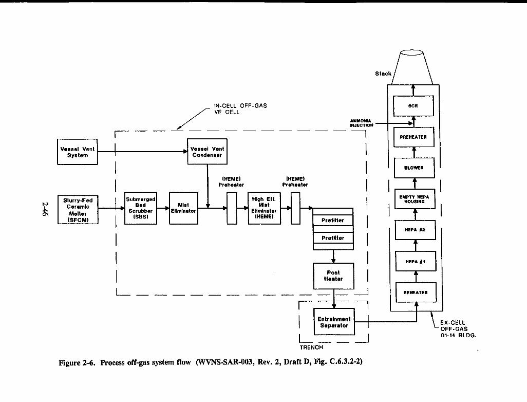
Stack
IN-CELL OFF-GASVF CELL
AMMONIAINJECTION
F - - - ---- ---I hi Vessel Vent
I ~~~~~CondenserI
I ItHEME) lHEME)
_ _ _ _ Preheater Preheater I I
I
I OFF-GAS01-14 BLDG.
I ' _ ETRENCH
Figure 2-6. Process off-gas system flow (WVNS-SAR-003, Rev. 2, Draft D, Fig. C.6.3.2-2)

Table 2-5. Off-gas system design data (WVNS-SAR-003, Rev. 2, Draft D, Table C.6.3.1-1)
[Item Component Description
1 Vessel Vent Header Uninsulated, 150 mm (6 in.), 304 SS Schedule 40 pipe
2 Vessel Vent 304L SS, 3.2 GJ/h (3 x 10⁶ BTU/hr) vertical shell and U-tube heat exchanger, 760 mm diam.Condenser by 3,350 mm high, 343 each 19 mm (3/4 in.) 18 BWG tubes
3 Submerged Bed Hastelloy C-22 receiver vessel, 2,400 mm diam. by 3,30 mm tall, 5.5 m3 working volume.Scrubber (SBS) Inside the receiver vessel is a Hastelloy C-22 scrubber vessel with 2.27 mm3 capacity, Inconel
690 downcomer, 150 mm (6 in.) in diam., bed of 10 mm diam. ceramic spherical packing.
4 Mist Eliminator 304L SS housing; knitted 304 SS wire mesh pad, 360 mm diam. & 150 mm thick. Pad isdesigned for 200 mm/s upward face velocity for particle capture by impaction.
5 HEME Preheater 304L SS housing; 50 kW, 480 volt, 3 phase, electrical resistance immersion style elementsheathed in Incoloy 800
6 High Efficiency Mist 304L SS housing 1,070 mm diam. by 4,060 mm tall, with wound fiberglass mesh pad 76 mmEliminator (HEME) thick, 610 mm inside diam., & 3,050 mm tall. The pad is designed for 1,500 mm/min to 12
m/min horizontal face velocity for particle capture by Brownian motion
7 Filter Preheater 304L SS housing; 50 kW, 480 volt, 3 phase, electrical resistance immersion style elementsheathed in Incoloy 800
8 Prefilter Assemblies 304L SS housing with two HEPA elements in series
9 Postheater 304L SS housing; 50 kW, 480 volt, 3 phase, electrical resistance immersion style elementsheathed in Incoloy 800
10 Duct to 01-14 Insulated 250 mm (10 in.) 304 SS; Schedule 40 pipeBuilding l
11 Entrainment 250 mm (10 in.) 304L SS Schedule 40 pipe housing slanted baffles for droplet capture bySeparator impaction

Table 2-5. Off-gas system design data (WVNS-SAR-003, Rev. 2, Draft D, Table C.6.3.1-1) (cont'd)
Item Component Description
12 Reheater 304L SS housing; 60 kW, 480 volt, 3 phase, electrical resistance immersion style elementssheathed in Incoloy 800
13 HEPA Filters 304L SS housing holding two parallel filter trains each having two HEPA elements in series
14 Blowers Rotary lobe, positive displacement blowers; adjustable frequency drives with set point for 37and 42.5 m3/min (1300 & 1500 ACFM); 75 hp, 460 volt, 3 phase
15 Preheaters Insulated 304L SS housings holding two 101 kW, 480 volt, 3 phase, electrical resistanceimmersion style element sheathed in Incoloy 800
16 NOX Destruction Insulated 321 SS vessel 4,300 mm tall and 1,000 mm diam., housing a catalyst bed, downflowReactors design, 890 mm of zeolite based catalyst in the form of 6 mm Raschig rings, plus 230 mm of
zeolite based catalyst in the form of 1.6 mm extrudate
17 Ammonia Storage Carbon steel tank 5,200 mm tall and 1,070 mm in diam. having a 3.8 m3 capacityTank
18 Ammonia Vaporizers 304L SS housings; 18 kW, 480 volt, 3 phase, electrical resistance immersion style elementssheathed in Incoloy 800
19 Off-Gas Discharge Insulated, 200 mm (8 in.) SS pipeDuct
00

.- - ---- -______ e-u
- A, l-or wl.
no .0""t .n
.t1.
ouM.
A.US cU
VENTILATION SUPPLY SYSTEM VENTILATION EXHAUST SYSTEM
P - Prefilter
H - HEPA
Figure 2-7. Ex-cell off-gas system components (WVNS-SAR-003, Rev. 2, Draft D, Fig. C.5.4.1.1-3)

is cooled in transfer. The entrainment separator is located in the lowest elevation of the off-gas line sothat it can drain the entire off-gas duct. Condensed liquid drains to the south sump of the VC, where itis cycled back into Tank 8D-4 by the waste header system. Next, the off-gas is reheated before enteringmore HEPA filters and the blower and exiting from the stack. An ammonia system is used to treat theoff-gases before leaving the stack for abatement removal of oxides of Nitrogen (NOX). All off-gasequipment in the 01-14 Building is designed for manual maintenance since the prefilter assembly withinthe VC is expected to prevent significant contamination from reaching the ex-cell off-gas equipment. TheHEPA filters are monitored routinely so they can be changed out if the radiation field rises to asignificant dose level. Also, the pressure differential across each HEPA filter is continuously monitored,and the installed backup HEPA filter train would be automatically valved into service if the differentialpressure exceeds a preset value.
The NOX abatement catalyst bed is expected to collect a small quantity of radionuclides, so thatthe dose at 2 ft should be less than 7 mrem/hr after 1 yr of operation (Vance, 1989).
The ammonia system within the 01-14 Building was reviewed for its potential fire hazard sinceany fire in Building 01-14 could put the off-gas equipment there at risk. Anhydrous ammonia is storedin a 1,000-gal. tank north of the 01-14 Building. It is used in the selective catalytic reduction (SCR)technique to reduce nitrogen oxide emissions. The tank is instrumented and fitted with redundant pressurerelief valves, a solenoid-operated shutoff valve, and excess flow check valves, and it is protected witha water-based suppression system for fire protection, vapor reduction, and reduction of concentration.Anhydrous ammonia is DOT-classified as a "non-flammable gas" per NFPA 49, and NFPA 325 M listsan ignition temperature of 1,204 'F, with lower and upper flammability limits of 15 and 28, respectively(West Valley Nuclear Services Company, Inc., 1994c). The conditions for an anhydrous ammonia firerequire several simultaneous unfavorable circumstances, so that a single contributing factor would not besufficient to cause an anhydrous ammonia fire.
A significant leak of anhydrous ammonia that could cause a health hazard to operating personnelwith important administrative duties has a higher annual probability (5.2 x 10⁻³ for loading accidents)than an anhydrous ammonia fire (10-4 to 10-6), per Table C.9.3-6 of WVNS-SAR-003. Potential causesfor a significant leak include human error during tank filling, impact by a vehicle, impact by tornadomissiles, impact by components of the 01-14 Building during a seismic event, or impact by items beingsuspended by an overhead crane. Protection of operating personnel is provided by a water-basedsuppression system for vapor reduction and reduction of concentration. As noted previously, operationof off-gas process equipment within the 01-14 Building is not crucial to radiation safety since the prefilterassembly within the VC is expected to prevent significant contamination from reaching the ex-cell off-gasequipment.
Downstream of the SCR unit, ammonium nitrate (NH4NO3), a potential fire and explosionhazard, is generated in very small quantities (2g/yr of operations). The potential for generation andaccumulation of NH4NO3 in the off-gas system was evaluated along with the physical and chemicalconditions that must exist for the compound to be hazardous (Goles, 1990). No credible mechanism foraccumulating exhaust system combustibles downstream of the SCR could be identified. The necessaryconfinement conditions for deflagration and/or explosive hazards cannot be established by the very limitedquantities of NH4 NO3 involved. Temperature conditions required to support spontaneous combustion ofthe NH4NO3 cannot be obtained at the stack, which is the only likely location where a combustibleinventory could develop.
2-50

For normal operations, the confinement system represented by the off-gas processing systemwithin the VF is required to function to maintain cumulative operating releases and doses below pertinentlimits. Off-gas releases are discussed in Section 2.3 of this SER. Accident conditions are discussed inSection 2.4 of this report, where it is noted that no active role is required of the off-gas processing systemto maintain on-site and off-site doses within EGs.
Margin of Safety
In-cell support framework and interconnected process components have been reviewed forstructural and anchor integrity. The in-cell off-gas framework was designed for structural integrity andanchorage under UBC seismic Zone 3 force with an importance factor of 1.5. The margin of safety forin-cell process off-gas equipment is listed in Table C.5.2.6-2 as greater than 1.7 xDBE for both yieldingof the frame and support failure.
Ex-cell off-gas equipment includes the off-gas trench and the equipment in the 01-14 Building.Ex-cell off-gas equipment is not seismically qualified; it is not required to maintain on-site and off-sitedoses within EGs. Since the 01-14 Building was not designed to withstand tornado loads, the off-gasequipment there would not be expected to survive the DBT. The in-cell filters are expected to collect thesignificant proportion of off-gas radioactive contaminants [decontamination factor (DF) = 105], with theresult that releases from the ex-cell off-gas equipment, due to a DBT, would not exceed acceptable limits.
Defense-in-Depth, As-Low-as-is-Reasonably-Achievable
The in-cell process off-gas equipment is designed with parallel and redundant HEME units andHEPA filter exhaust trains. Those components that are not installed in a redundant arrangement can bereplaced remotely, and spares for each are available. In-cell filters are designed to withstand the DBE.HEPA filters are monitored for radiation and differential pressure to indicate when they need replacement.The in-cell process off-gas equipment is protected by another barrier to release, that barrier being the VCreinforced concrete boundary and its special doors and viewing windows.
The ex-cell off-gas system is designed with redundant equipment trains so that a spare systemis available when maintenance is required or in case of equipment failure. Redundancy is provided forthe reheater and HEPA filter trains. The blowers that draw air through the entire off-gas system areprovided with double redundancy so that there are two backup units. Thus, during maintenance, a backupblower is still available. The pressure relief valves on the blower discharges relieve to the suction sideof the blowers, so that pressure is not relieved to atmosphere and confinement is maintained.
Ex-cell off-gas system components are protected by at least one additional confinement barrier(the trench for the off-gas pipe between buildings and the 01-14 HVAC system for equipment within the01-14 Building).
The NOX abatement system is also provided with redundancy so that cascading pressure controlin the off-gas system is maintained.
The ex-cell off-gas system is monitored and partially controlled from the VF CR.Instrumentation is energized with a UPS in case of loss of available electrical power.
2-51

Loss of off-site power supply is protected against by a diesel generator unit and UPSs. Active(powered) function of the off-gas system is not required, however, to maintain occupational and publicdoses well within acceptable limits.
Expected annual release rates and concentrations of radionuclides released from the process off-gas stack are provided in Table C.6.2.3-1 of WVNS-SAR-003, and they are discussed in Sections 2.1.3.7and 2.2.1 of this SER.
Evaluation: This design complies with the concept of cascading pressures to controlthe flow of contaminated air (in this case, off-gas) from less contaminated zones tomore highly contaminated zones. In addition, multiple barriers of confinement areutilized. All off-gas lines lie within another confinement barrier (e.g, the VCfor in-cellrelease, the off-gas trench between buildings, and the 01-14 Building HVAC).Defense-in-depth is incorporated in the design by (i) redundancy of importantcomponents including both in-cell HEPA (pre-)filters and those HEPA filters locatedin the 01-14 Buildingfartherdownstream; and (ii) redundancy of blowers in the 01-14Building. The potential for development of hazards associated with anhydrousammonia and with ammonium nitrate has been adequately considered and is notsignificant.
The design and analysis of the process off-gas structure is in accordance withstandard engineering practice. Use of a dynamic analysis for the seismic event isacceptable based on the calculated modes of the system that lie in the elevated portionof the required response spectra.
2.1.3.8 Gaseous Waste Stream-Heating, Ventilation, and Air Conditioning System
Although the HVAC systems are described in various places in the WVNS-SAR-003, a briefdescription is provided here for to clarify and to identify pertinent design features. For further details,refer to the WVNS-SAR-003, particularly in Sections C.4.5.2.5, C.4.5.3.3, C.5.4. 1 and its subsections,C.5.5.2, C.5.5.3 and its subsections, C.6.3, C.6.3.2, C.7.4.2, C.8.3.3, C.9.4.4, C.9.4.5, C.9.4.7.2,C.9.4.8, C.9.4.9, C.9.4.10, C.9.6.2.1, C.9.6.2.2, and C.9.6.3.
Description
The three primary functions of the HVAC systems are: (i) to direct airflow to aid inconfinement, (ii) to control the operating environment of equipment and components, and (iii) to controlenvironmental conditions for operating personnel. The direction of airflow is controlled so that ventilationflows from areas with lower potential for radiological contamination to areas with higher potential forradiological contamination. This is achieved by control of ambient air pressure between multiple zoneswithin the facility. This concept of cascading pressures is made effective by controlling dampers and otherflow restrictors between each of three ventilation zones.
For the VF HVAC, the three ventilation zones are illustrated in Figure 2-8, taken from Figures5.4.1.1-1 and 5.4.1.1-2 of the WVNS-SAR-003. Zone I areas are designated as those that contain thehighest level ("a significant amount") of airborne contamination during normal operations. Zone Iincludes the VC, which contains the melter and batch tanks for glass-forming slurry containing HLW.Zone II is immediately adjacent to Zone I, and it provides a buffer to Zone I releases. Zone II could
2-52

Figure 2-8. Ventilation zones of the vitrification facility (WVNS-SAR-003, Rev. 2, Draft D, Fig.C.5.4.1.1-1)
2-53

contain airborne activity, but airborne activity in Zone II is anticipated to occur only very infrequently.Zone III areas are expected to remain free of any contamination. Zone III includes those areas that areplanned to be continuously manned, such as the main CR. Infiltration air for ventilation flows fromoutside into Zone m, to Zone II, and finally to Zone I, before being evacuated through banks of multipleHEPA filters for control of radiological releases through a stack. The use of such controlled zones indirecting the flow of any airborne contamination is common practice when handling radioactive materials.
Control of infiltration air also depends on the integrity of zone boundaries, the most importantof which is that for Zone I. Confinement structures supporting the HVAC design are discussed in Section2.1.3.3 of this SER, including special doors, windows, the VC, and infiltration.
Significant HVAC design features include the use of redundancy and diversity in componentsfor reliability control; limiting flow to 30,000 cfm; instrumented control to control infiltration and exhaustflows; accessibility of filters for change-out; accessibility of components for change-out; ability to isolatefans and filters for maintenance; test sections provided for HEPA filter testing with DOP; and componentdesign and testing conforming to ANSI/ASME N509 (American Society of Mechanical Engineers, 1976)and ANSI/ASME N510 (American Society of Mechanical Engineers, 1975), respectively. Primary HEPAfilters are located as near as possible to contamination sources to limit spread of contamination. ThreeHEPA flowpaths are available so that redundancy for the in-cell filtration is assured at all times, includingmaintenance to change-out filters. Each flowpath includes a prefilter and a HEPA filter. The prefilter isidentical to the HEPA filter but, since it cannot be DOP-tested if it is replaced, it is not referred to asa HEPA filter. It is, however, DOP-tested prior to initial installation.
The VB HVAC system is designed to maintain confinement of Zone I during and after a DBAor event. Infiltration air entering Zone m of the VB is HEPA filtered as it is conditioned for temperature,except at entry doorways. HEPA filters are also located between Zone I and Zone II to filter inadvertentbackflows from Zone I during upset conditions. Stairways are pressurized and ventilated in accordancewith NFPA requirements for safe passage of personnel. Particulate loading of exhaust filters is reduced(and frequency of change-out period is extended) by the use of prefilters.
Dual systems are in place for monitoring and controlling VC ambient air pressure; this isimportant in maintaining the cascading pressures between zones. If the VC negative pressure cannot bemaintained by the system, an automatic system isolates the VC and shuts off the supply fan. Duringnormal operations, VC vacuum is maintained by an automatic system that has the ability to controlexhaust air flow, pressurize stairways, operate vacuum relief dampers, and open dampers to provideoutside cooling air to the SFR and Crane Operating Aisle. Smoke detection equipment can alsoautomatically isolate supply and exhaust fans to control the spread of fire.
Temperature and humidity control for maintenance of equipment operating conditions andhuman comfort is provided by chilled water and refrigerant systems (for cooling) and steam and electricalheating systems (for heating). The VC temperature is cooled to near 100 'F by removing process heat(from the melter and evaporation of excess slurry water) through in-cell coolers. The in-cell coolers aresuspended from the VC roof, and they are designed to induce filtered VC air through a heat exchangeremploying chilled water. Exhaust air from the in-cell cooler is directed toward the sources of processheat. Operating aisles and the CR are maintained at temperatures suitable for occupancy of shift operatingpersonnel by circulating air through one of two heat exchangers (one spare) employing chilled water and
2-54

refrigerant for cooling and electrical heaters for heating. Supply air to the CR is HEPA filtered to preventcontamination from airborne radioactive particles. CR air is automatically isolated via redundant smokedetectors.
Air exiting the VC is exhausted from the three in-cell filters via three dedicated ducts, each ofwhich may be valved off for isolation. Exhausted air passes through flexible connectors at the secondaryfilter unit.
The flexible connectors serve to seismically isolate the secondary filter equipment from vibrationsuch as that associated with seismic events. The flexible connectors are made of polychloroprene, whichhas a kindling temperature of 1,652 'F and which will not support combustion without a sustained heatsource. Three potential sources for combustion for the flexible connectors were considered in the reviewof WVNS-SAR-003: (i) molten glass (temperature to 1,225 'C, or 2,235 'F), (ii) combustion of processammonia, and (iii) acetylene combustion potentially available during maintenance. Molten glass does nothave an available path to ignite the connector. Process ammonia is used in the 01-14 Building, which isseparate from the VB, and there is no available path for a sustained ammonia fire to reach the connector(West Valley Nuclear Services Co., Inc., 1994c). Unplanned maintenance in which acetylene might playa role would be under administrative control, via WVNS Welding Codes and Procedures and theIndustrial Work Permit (Westinghouse Risk Assessment Services, 1994). Inadvertent surface combustionof the connector that might occur in spite of such control would only be possible if the flame weredirected at the connector. WVDP personnel would obviously avoid this, but, if it were to occur, such anincident would be immediately evident to maintenance personnel. Minor surface deterioration that mightresult would be insignificant with respect to the function of the flexible connector.
In the secondary filter unit, three parallel trains, each containing three HEPA filters, areavailable for further filtration of air exhausted from the VC and the in-cell filters. Like the in-cell filters,a redundant filter is available at all times, even when one filter is being changed out during maintenance.The exhaust plenum of the secondary filter unit is shared with exhaust from dual HEPA filters thatprocess the prefiltered exhaust air from Zone II and III ex-cell areas. Air is drawn through the exhaustplenum by two parallel exhaust fans, each of which can be isolated for maintenance or replacement. Sincetwo fans are available, no redundant fan would be available if one fan were inoperable due tomaintenance or replacement. The HVAC stack, which is separate from the off-gas processing systemstack, is fitted with a relief exhaust damper so that HVAC exhaust can continue if the stack becomesunserviceable.
The release point from HVAC exhaust is located to minimize the possibility of drawing incontaminated air via the HVAC infiltration air.
For protection against tornadoes, tornado dampers are provided to prevent backflow during theshort-term, low-pressure tornado event (Kupp, 1989). The dampers require no external power source tooperate, and they are located at the CMR intake, the HVAC CR supply, and the SFR supply. Forprotection against tornado missiles, tornado missile barriers are installed to protect the exhaust duct whereit exits the VB up to the pressure relief valve, from which point the duct is considered expendable in atornado event. The pressure relief valve, which bypasses the stack in case of tornado damage, is alsoprotected with a tornado missile grating. Other HVAC ducts and accessories are protected againsttornadoes and tornado missiles by the passive confinement barrier provided by the reinforced-concretevault, special doors, and shielded viewing windows.
2-55

The chiller equipment room is ventilated by a dedicated axial fan, that is thermostaticallycontrolled and supplied by air from outside the building through a fail-open damper. The chillerequipment room is not supplied with ventilation from the ex-cell ventilation system.
Standby power is available to the valves isolating the VC, to fan controls, and to stair fans.
Three distinct ventilation systems provide active confinement: (i) the VB HVAC system, whichalso services the VC; (ii) HLWIS and EDR Ventilation, which utilizes the existing main plant and headend ventilation systems; and (iii) the process off-gas system, which is discussed in Section 2.1.3.7. Inaddition to the VB HVAC (which includes in-cell coolers VF CR HVAC, and DGR HVAC),WVNS-SAR-003 includes discussions on CCB HVAC, 01-14 Building HVAC, and main plant HVACHEV (which serves the HLWIS). Discussions on design basis and description for each of the other HVACsystems (other than the VB HVAC) are given in other DOE-approved safety documentation.
The EDR, which is part of the VB, normally receives ventilation air from the "truck lock," withwhich it interfaces. Exhaust air from the EDR is transferred to the CPC, which is kept at negative airpressure by the HEV system. The transfer tunnel, which also interfaces with the EDR, is ventilated bythe Vitrification HVAC system. Air transfer between the two systems can occur when the transfer tunnelis being used to transfer equipment between the VC and the EDR. Air transfer is minimized bymaintaining the Transfer Tunnel and the EDR at the same pressure under normal operation. A furtherstep to minimizing infiltration to the EDR from the transfer tunnel can be taken by closing both doorsat the ends of the transfer tunnel.
The DGR requires ventilation when the diesel is running for cooling and combustion air, andthis ventilation is provided from outside air through louvers, that fail open upon loss of power. When thediesel is not running, HVAC is provided by a supply duct from the VB HVAC and by a local electricheater.
The CCB HVAC is separate from the VB HVAC, and it is not required to process air forradiological safety. The CCB is ventilated in a once-through arrangement, with infiltration air heated inwinter with steam. In addition, the CCB scale room is ventilated with a filtered fume hood, and suppliedwith its own air intake to ensure a supply of fresh air. The CCB exhaust air is adequately separated fromthe VF and CCB air intakes.
The 01-14 Building HVAC conditions air for the VP off-gas equipment that resides there. It alsoincorporates the concept of cascading pressures so that ventilation flows from areas of lessercontamination to those of higher contamination. Two stages of HEPA filtration are employed to removecontaminants from either the process off-gas system or the ammonia system before blowers discharge airthrough the stack (separate from the off-gas stack).
The 01-14 Building HVAC contributes minimally to radiological safety, since (i) the off-gasstream is relatively free of contamination by the time it reaches the 01-14 Building, and (ii) contaminationfrom the off-gas processing equipment is only possible in the event of breach of off-gas processingequipment confinement. The 01-14 Building HVAC is reportedly discussed in other DOE-approvedWVDP safety documentation.
Ventilation for Pump Pit 8Q-2 (above Tank 8D-2) and Pump Pit 8Q-5 (diversion pit) is providedby the WTFVS, which is outside the scope of WVNS-SAR-003, and discussed in other DOE-approved
2-56
WVDP safety documentation. Ventilation for pump pits is provided by the WTFVS. Pump pits aremaintained at below ambient pressure to direct air flow into the pits and toward the WTFVS. TheWTFVS has redundant ventilation trains, each of which includes a mist eliminator, a heater, a roughingfilter, and two HEPA filters in series, with exhaust through the PVS stack. During maintenance activitiesin which the pit cover is removed, ventilation is provided by an 8-in. SS line which is ventilated by thePVS. Aspects other than ventilation for pump pits and the Diversion Pit 8Q-5 are discussed in Section2.1.3.1 of this SER.
In keeping with the "Graded Approach," each of the HVAC systems and their components areassigned safety classes and quality levels that are listed in WVDP-204. With respect to radiologicalhazards, limitation of Safety Class B to those components that provide primary confinement (e.g.,concrete hot cell, transfer tunnel, VF shielded viewing windows, etc.) and VC HVAC (e.g., duct-cellexhaust system, primary HEPA filter bank, etc.) is consistent with the safety classification criteria givenin Table 2 of WVNS-204 since they are both confinement barriers that are required to remain functionalunder site-specific design basis events. The HVAC CR is a new engineered confinement barrier structurerelied on during accident scenarios, including natural phenomena-induced accident (design basis event)scenarios.
Margin of Safety
The exhaust system has been designed to maintain structural integrity and remain functionalduring and after the postulated occurrence of the design basis events in combination with normaloperating loads such as temperature and pressure. The HVAC ducts and their supports, primary HVACHEPA filter units, and secondary HVAC HEPA filter units are protected against wind, tornado, andtornado-generated missiles by reinforced concrete structures, special doors, shielded viewing windows,and tornado missile grating.
Releases to the environment can reasonably be expected to be very small, if not negligible,during all accident conditions and especially during natural phenomena-induced accident conditions dueto the fact that the SFR, HVAC CR, DGR, and the associated controls and equipment of these rooms aredesigned to withstand extreme natural phenomena events.
Although not needed to keep doses within EGs, primary filters within the VC are expected tomaintain integrity and remain functional under loading from design basis events. The VB HVAC systemcan withstand a relatively large seismic event, as shown in Table C.5.5.3-2 of WVNS-SAR-003. Thistable shows margins of safety against design basis events for components of the HVAC system. For thein-cell primary HEPA filter, the margin is listed as greater than 3 XDBE against structural or functionalfailure. The other in-cell (secondary) HEPA filter, the ducts, and their supports are listed in the table ashaving greater than 6 x DBE against structural or functional failure. This margin was established by bothtesting and dynamic analysis. The same margin is listed for the ex-cell primary HEPA filter. For exhaustfans, which draw air through the HEPA filters and exhaust air to the atmosphere, the margin of safetyagainst either structural or functional failure is listed as greater than 4xDBE. For all other componentsin the table, the margin of safety against seismic loads is the same, greater than 1 XDBE. All HVACcomponents listed in Table C.5.5.3-2 of WVNS-SAR-003 should structurally survive the DBE, and theHVAC filters should remain functional. In-cell coolers, which provide a cooling function in-cell, aredesigned to remain in place, but not necessarily remain functional, during a DBE.
2-57

Analyses show that all major process components in the VC pit have a seismic design capacitysufficient to prevent their ultimate failure or collapse from extreme environmental loading in excess ofthe DBE. Continued operation of the VC HVAC system during and after a DBE event is expectedbecause the HVAC CR, controls, blowers, filter units, UPS, and associated standby diesel generator areDBE-qualified.
No margins were listed in the table for resistance to tornado loads, although it would appearthat such would be appropriate for the pressure relief valve and tornado dampers, as a minimum.
Defense-in-Depth, As-Low-as-is-Reasonably-Achievable
Primary HEPA filters are located as near as possible to contamination sources to limit spread
of contamination. Three HEPA flowpaths are available so that redundancy for the in-cell filtration isassured at all times including maintenance to change-out filters. Each flowpath includes a prefilter anda HEPA filter.
Length of runs of ventilation ducting is minimized to reduce lengths of contaminated ductwork,
and inaccessible areas that could accumulate radioactive materials are avoided in the design by use ofremovable inspection covers.
Dual systems are in place for monitoring and controlling VC ambient air pressure; this is
important in maintaining the cascading pressures between zones. If the VC negative pressure cannot bemaintained by the system, an automatic system isolates the VC and shuts off the supply fan.
Multiple flow paths are available for reliable exhaust air flow, and each flow path incorporatesmultiple HEPA filters. A backup exhaust fan is available, but during maintenance or replacement of oneof the fans no backup would be available. A relief exhaust damper in the stack allows continued operationif the stack becomes unserviceable. HVAC exhaust is located away from points at which ventilation airenters the building.
Valves used to isolate the VC, fan controls, and stair fans are all provided with standby power.
Multiple barriers for main plant confinement are as follows: first barrier, piping and equipment
to contain the HLW; second barrier, concrete cells of the building and their SS liners and sumps; andthird barrier, both the drain system to remove liquids and the main plant HVAC system to filter effluents,maintain cascading pressure zones, and maintain acceptable environmental conditions in work areas.
Active confinement is provided by the HVAC system by maintaining negative internal pressurerelative to outside air pressure and relative to adjacent areas in the VB. A filtered HVAC system draws
air through the VC and adjacent areas via a system of cascading pressures, as explained in Section2.1.2.1 of this SER.
The HVAC system used to maintain proper environmental conditions and negative pressure in
the third confinement barrier consists of systems that control liquid or gaseous effluent from the VC. Thefirst confinement barrier for the HLW slurry and molten glass consists of process vessels, piping, orcontainers in direct contact with the HLW, while the second confinement barrier is the VC that has a SSliner up to the 22-ft level. (For liquids spilled within the VC, a below-grade SS-lined process pit andsumps provide confinement.)
2-58
In the event of loss of electrical power, a standby diesel generator is available to powerinstrumentation, controls, and the exhaust fan. The rated capacity of the diesel generator is about50 percent greater than the standby loads required. Rated capacities of all UPS units exceed powerrequirements by more than 40 percent. Valves and dampers which are required to operate in the eventof loss of off-site power are supplied with an UPS and pneumatic accumulators sized for multipleoperations. If the Vitrification HVAC filtration and exhaust system is still unavailable, valves close toisolate Zones I and II from Zone m and supply air is shut off. These valves can be operated withuninterruptible battery power to solenoid valves and hand switches. If cell pressure builds duringisolation, it may be vented manually by opening certain isolation valves.
The VF exhaust stack is monitored for radioactivity and high radiation levels, with annunciationin the VF CR.
Redundancy in design is reflected in the in-cell coolers, for which four are installed and twoare required to maintain in-cell temperatures within acceptable limits during maximum heat loads. Twofans, one at the inlet and one at the outlet, are fitted to each cooler, and only one is needed forfunctionality.
The Chilled Water System (CC) supplies chilled water at full-flow during operations, and theCC heat is rejected through heat exchangers to three refrigerant chillers (one air-cooled, two water-cooled). The CC system also supplies chilled water for air cooling in the CR (two air handling units) andelsewhere ex-cell (one air handling unit). The potential for contaminating the CC system through apossible break in the lines feeding the in-cell coolers is limited by the following: (i) CC pressure isgreater than VC air pressure, so VC air would not enter the CC system; (ii) VC air would containminimal particulate contaminants under all conditions during which the melter and process vessels (heatsource) remain in operation; and (iii) if one or more in-cell coolers must be replaced, the melter andprocess vessels need not remain operational, and no driving force exists to draw contamination into theCC system.
Evaluation: The population of structures, systems, and components considered in theWVNS-SAR-003 for the vitrification HVAC system includes all those important toactive and passive confinement. The scenarios considered in analysis of margins ofsafety for the structures, systems, and components of the IVAC are appropriate andcomplete. The margins of safety for the structures, systems, and components of thevitrification HVAC system indicate that none shouldfail under design basis loads. Forthose HVAC system components most important to confinement (primary andsecondary filters, ducts and duct supports, fans, and control), margins of safety rangefrom 2.1 xDBE to IOXDBE, providing confidence they will survive the DBE. Themargins were developed using both standard engineering practice in design andanalysis as well as seismic qualification testing.
For the two parallel HVAC exhaust fans, no redundant fan would be available if onefan were inoperable due to maintenance or replacement. These fans are assignedsafety class B.
2-59
Other Systems
There are many systems at the site that provide support to the effective operations of the VP.The important safety-related systems have been discussed in sections 2.1.3.1 through 2.1.3.8. The others,not described here specifically, were deemed to be non-radiological and non-safety-related, although theymay have a secondary or tertiary impact on radiological safety.
2.1.4 Administrative Features
2.1.4.1 General Controls
The VP at the WVDP is a batch operation, where a limited quantity of waste from Tank 8D-2is processed at any given time. This results in maintaining a low inventory within the processing systemsand assists in minimizing the radiological source term during any natural or man-made hazard conditions.As described earlier, the design philosophy for the VF is one that emphasizes the confinement of potentialradiological releases. Toward this approach, the primary component that facilitates confinement is the in-cell structure of the VF. Significant credit is taken by the WVDP for the capabilities of the passivestructures to mitigate any level of radioactive releases. Also, the design of the operational controls forthe plant rely more on manual or semiautomatic controls than on automatic controls. This leads to theneed for a large number of administrative controls to be exercised in the operation of the vitrificationplant.
WVDP has put in place a detailed, formal operations program that elaborates on the functions,staff responsibilities and interactions, operating practices, process controls and supportingcommunications, staff qualifications and training, reporting and record-keeping practices, safetyconsiderations, testing and surveillance, and quality control and quality assessment. The operationsprogram is developed to meet the requirements of DOE Order 5480.19-Conduct of OperationsRequirements for DOE Facilities (U.S. Department of Energy, 1990). Based on DOE Order 5480.19 andother industry practices, WVDP has developed a manual, Westinghouse Conduct of Operations Manual,WVDP-106, for the vitrification operations. WVNS has implemented WVDP-106, and it is part of thecontrolled document system at the site.
A key to the operations program for WVDP is the "graded approach." Here, in the gradedapproach, the implementation of the scope and depth of any activity is controlled by the anticipatedimportance and impact on safety, health, and environmental issues. The HLW and waste processingactivities have been assigned the highest importance at the site. Significant training is being provided toall the key staff involved in the operations.
Evaluation: Administrative controls play an important role in the safe operations ofthe VP at WVDP. The operations program presented in WVNS-SAR-003 involvesmajor decisional roles for the various operations staff during the conduct of the VP.Many of the staff will perform key safety-related tasks. The risks of not executing anyof the staff roles have not been assessed in the WVNS-SAR-003 for the operationalconditions. However, it is recognized that this will not affect releases resulting fromany accident where operator or staff involvement is not considered.
2-60

The graded approach used by the DOE places emphasis on the most criticalcomponents or processes in the system and is controlled by WVNS policy (WVNS-110).However, the ALARA program is controlled by other documents, namely, WV-984,ALARA Program and WVDP-010, Radiological Control Manual. Future updates toWNS-SAR-003 need to describe the hierarchy of the implementation documents suchthat there is a clear understanding of the operational practices to be followed by theworkers at the site.
2.1.4.2 Safety Implications and QA
The project organization in support of the vitrification campaign is organized along functionallines. The technical staff are qualified and trained to support specific job functions for the campaign.Emphasis has been placed on developing a safety culture at the WVNS. Appropriate reporting practicesfor various activities and abnormal events have been developed. Training on operating procedures areprovided to staff. Alarm systems with remote monitoring are in place. The communications within thefacility are carried out by public address system, emergency all-page system, radio, and telephone.Hazardous materials at the facility are controlled by DOE Order 5480.4, rules of the U.S. EnvironmentalProtection Agency (EPA) and other governmental agencies, and established industrial practices.
Pre-operational testing and subsequent operations are conducted using Test InstructionProcedures (TIPs), Special Instruction Procedures (SIPs), Hot Operations Test Plan (HOTP), andStandard Operating Procedures (SOPs). SOPs support both cold and hot operations. These proceduresare developed, documented, approved, and controlled by the WVNS Policy and Procedures Manual,WVDP-1 17. The document control program was developed in accordance with ASME-NQA-1 (AmericanSociety of Mechanical Engineers, 1989).
WVNS has in place the Safety Review and Unreviewed Safety Questions Programs. Also, it hasa comprehensive configuration and document control program. An extensive fire hazard analysis wasconducted and a fire protection program was developed.
Evaluation: Chapter 9 of WVNS-SAR-003 concluded that all the evaluation basisaccidents (EBAs) analyzed were below the EGs used to assess safety classes. As aresult, there are no specific administrative controls needed to support any technicalsafety requirements. The conclusion is valid because all the confinement barriers usedin the analysis were passive.
During operations, the administrative controls for worker radiological safety areappropriate and acceptable considering that the source term is limited and there isintensive training for operations staff and significant access and procedural controlduring operations. However, it is recommended that, from an ALARA perspective, thereduction of dose rates resulting from the continuous or long-term occupancy of thevitrification CR should be considered.
2.1.4.3 Human Factors
There are several situations during operations or under accident conditions that need humanintervention. A major part of the vitrification operation is also controlled by human action.
2-61

Evaluation: While training and personnel development programs are in place, thereare opportunities for man-machine interface problems. Cases are identified belowwhere improvements in operations can be made.
* To support the EBAs analyses, there are scenarios that require operator actionsbefore the standard 2-hr specification for any action (e.g., loss of CFMT ventcondenser cooling, SFCM off-gas jumper failure). Here, special training forpersonnel or mitigating conditions should be identified.
* The main plant CR is not continuously monitored. Remote video and audiblealarms are provided. Here, the responsibilities of the various personnel and theaction party need to be specified.
* The equipment operations for the turntable and the transfer of solutions from theCCB to the VC are not controlled from the CR. Here, the communication andcoordination between the various operators have to be examined closely and mayneed a special training program.
2.2 WASTE MANAGEMENT
The vitrification operations generate gaseous, liquid, and solid wastes. The approach taken bythe WVDP to manage these wastes, in particular the radiological wastes, is the subject of discussion inthis subsection.
In the VP, the conversion of liquid wastes from Tank 8D-2 to a solid form is considered as theprimary product of the operations, and not as a waste. The handling of the HLW generated from thisoperation is recycled through the system by design. This is the primary mode of waste minimization.
2.2.1 Gaseous Wastes
Off-gas is the main source of waste resulting from the vitrification operations. During normaloperations there are no expected off-gas releases at the pump pits near the WTF where the HLW sludgeis transferred by pumps to the transfer piping. From this point on, the generation and transport of the off-gases is fully contained within process tanks and piping before any release to the atmosphere via thestacks. The main source of off-gas is at the SFCM. The off-gas from the SFCM is processed through theSBS and mist eliminator and then combined with off-gases from the CFMT, the MFHT, and neutralizingtanks. Before any off-gas is released to the stack there are filtration and drying systems to trap andminimize releases to the environment. To ensure containment of the off-gas within the transport systemin the in-cell area, a slight vacuum is maintained in the system. Redundancy in the off-gas treatmentequipment exists, primarily to facilitate maintenance functions.
The HVAC system in the VC is designed to operate during design basis accidents (DBAs). Thedesign is such as to provide a flow into the VC and limit any outside releases. Operational doses topersonnel are also minimized by incorporating appropriate design features for the filters. Redundancy isalso provided in the filter system to prevent unfiltered transport or backflow of gaseous radioactivematerials.
2-62

Evaluation: The off-gas system layout with parallel filtration trains provides anadequate means to maintain a controlled flow path for the movement of off-gasesduring the VP. The off-gas system design assists in the minimization of gaseousreleases through the stack. Based on the data provided in Table C. 6.2.3-1 ofWVNS-SAR-003, the concentrations of radionuclides and the associated maximumannual releases from the stack are small under operating conditions. The levels shownare much less than that permitted under 10 CFR 72.104 and 10 CFR Part 20Appendix B Table 2 (Air Effluent Concentrations) criteria for individuals beyond thecontrolled area.
The radionuclide particles captured in the various filters in the off-gas stream aretreated as part of the solid waste disposal aspect of the project.
2.2.2 Liquid Wastes
Liquid wastes are generated as part of the activities in the waste header system, condensatesfrom the CFMT and other in-cell process vessels, rinse water from the canister decontamination system,and ex-cell off-gas condensates that collect in the VF drains. The HLW components of the waste arecycled back into Tank 8D-2, while the LLWs are treated as part of the integrated radwaste treatmentsystem program or is processed through the LLW treatment facility.
Evaluation: WVNS-SAR-003 describes the waste handling process for the liquidwastes adequately. However, there is no quantitative information about the expectedlevels of liquid waste that is generated per batch operation during waste vitrification.The LLW generated is classified as per 10 CFR Part 61, and a large quantity will beClass A type. The disposal of residual waste heels in the waste tanks at the end of thevitrification campaign has not been presented in the WVNS-SAR-003. This should beaddressed in a future WVNS-SAR-003 update and treated as part of thedecontamination and decommissioning plan.
2.2.3 Solid Wastes
The inventory of solid wastes will contain clothing and other anticontamination material usedduring the vitrification campaign. It will also include contaminated laboratory samples and containers,failed metal and nonmetal components from hot operations area, and spent off-gas and ventilation filters.West Valley has existing facilities to provide temporary storage for these materials. These materialscontain Class A, B, and C LLW.
Evaluation: Existing Lag Storage Facility at West Valley can provide temporarystorage for the solid LLW. Estimates of the quantities of the waste needs to beaddressed in the WVNS-SAR-003 to ensure the adequacy of the storage and handlingcapacity of the solid waste generated during the period of vitrification. It isrecommended that a plan for the removal and disposal of these materials will beaddressed in a future update of this WVNS-SAR-003 or in a new one.
2-63

2.3 OPERATIONAL DOSES
WVDP has approached the radiological dose issue on a defense-in-depth basis. The layers ofdefense assumed for the vitrification operations include; passive confinement barriers, wasteform andlimited inventory of waste at any given time, active confinement barriers, alarms and monitors, personneltraining, and administrative planning and controls. The important passive barriers for the vitrificationoperation are the thick concrete cell and shielding walls. Limiting the amount of waste processed at anytime keeps the source term controlled and thus supports the ALARA program at the facility. Activeconfinement is provided by ventilation and off-gas systems. Here, the system is designed to control thedirection of flow of contaminants and minimize the airborne radioactive components. Alarms andmonitors are placed in strategic locations to provide warnings as well as continuous data on any leaks inthe process systems. Section 8 of the WVNS-SAR-003 presents a series of internal WVDP guidelines anddocuments for the radiological safety considerations during operations at the site. These documents reflectrequirements of various DOE orders as well as industry practices adapted from the nuclear powergenerating industry. The documents provide both personnel training requirements as well asadministrative controls.
2.3.1 Radiological-On-Site
WVNS uses DOE Order 5480.11 for evaluating on-site radiological hazards. The VF is designedto be below the values described in the DOE order. Furthermore, as an operational strategy, thepersonnel doses are limited to one-tenth the depicted levels. The lower levels are attained partly by designand partly by administrative controls. The doses within the VC were calculated using the ISOSHLDcomputer code in conjunction with DOT-3.5 (DiBiase, 1986a,b). During operations, the VC is sealed andno human entry is permitted. The calculated dose rates adjacent to the cell indicate that the maximumdose rates below the 120-ft level is 0.023 mrem/hr while the highest was estimated at the 130-ft level of3.6 mrem/hr. The design criteria is 0.31 mrem/hr for an assumed 8-hr shift operation. Administrativecontrols are planned to limit doses to personnel in the higher radiation areas.
There are no on-site airborne or liquid releases anticipated during operations. However, alarmsare set at 0.25 mrem/hr at points of continuous occupancy, and at 2.5 mrem/hr at intermittent occupiedareas.
Evaluation: The principal criterion used for on-site radiation control is limiting theworker annual dose to 500 mrem. This criterion is one-tenth the occupational totalannual effective dose limit specified in 10 CFR Part 20. The criterion used for the on-site radiation limits is conservative. However, parts of the operating aisles of the VCwill require limitations to be placed on the time of occupancy to remain in compliancewith the WVDP criteria. The WVNS-SAR-003 has not attempted to identify specificlocations where the criterion will not be met. It is recommended that shieldingcalculations be performed for the areas where penetrations or local change in wallgeometry can cause higher dose rates. Such results will be usefid in developingappropriate survey locations and possible additional barriers if deemed necessary.
2-64

2.3.2 Radiological-Off-Site
The main sources of off-site radiation during operations comes from the off-gas system and theVB HVAC system. Only a small amount of radioactivity gets carried to the two stacks. The areas withpotential airborne radioactivity are ventilated in a controlled manner such that confinement ofcontaminants is expected. The estimated maximum dose for an off-site individual during 1 yr of operationof the HVAC system is 9.5 x 10⁻⁴ mrem and 0.2 mrem/yr for off-gas releases.
Evaluation: The calculated annual releases from airborne and liquid sources at thesite boundary resulting from normal operations is small (i. e., less than 1.3 mrem). Itis significantly below the annual, 25 mrem level prescribed in 10 CFR Part 72 for'any real individual who is located beyond the controlled area.'
2.4 ACCIDENT ANALYSIS
Section 2.1 of this SER discussed in detail the types of hazards, the design of the varioussystems, the design margins of safety, the defense-in-depth issues, the VP considerations, and thepotential for radioactive releases. In this section, an evaluation is made of the accidents considered inChapter 9 of the WVNS-SAR-003, and the resulting radiological consequences. The purpose is todetermine if there is adequate protection for the public and the on-site worker from credible accidents.To exercise judgment on the adequacy of the protection needed, the WVNS-SAR-003 has provided a setof EGs. The EGs cover both radiological as well as non-radiological accidents. The discussions in thissection relate only to the radiologically important aspects of credible accidents.
2.4.1 Accident Analysis Evaluation Guidelines
As part of the safety analysis, the consequences of the various accidents considered in theanalysis are compared to a set of criteria, referred to as EGs. The EGs for radiological hazards to thepublic (outside the controlled area) and to on-site personnel are presented in Figures 2-9 and 2-10,respectively. The EGs are based on the frequency of the hazard under consideration. In the calculationsperformed by WVNS for the consequence analysis, only the passive confinement barriers were used.
Evaluation: The NRC regulations, 10 CFR Part 20, 10 CFR Part 72, and 10 CFRPart 100, have deterministic values for doses for on-site and off-site applications.However, the classification of accidents as anticipated (probability > 10-21yr),unlikely (probability 10-4/yr to 10-2/yr), extremely unlikely (probability 10 6fyr to10-4/yr), and incredible (probability < 10 6/yr) based on Elder et al. (1986) andused in WVNS-SAR-003 is generally acceptable and consistent with industry practice.These probabilities are also consistent with NUREG 1150 (Nuclear RegulatoryCommission, 1989), where they are used as initiating accident probabilities. For thevitrification operations, the WVNS-SAR-003 has classified the various accidents on aqualitative basis, and the real distinction is between nature- caused accidents versushuman-induced events.
The public or off-site radiological criteria in Figure 2-9 have direct links with 10 CFRPart 100 and 10 CFR Part 72 for the extremely unlikely and unlikely categories, while
2-65

1E+02:
NATURAL PHENOMENA
25 rem
(DOE Order 6430.1A. 10 CFR 100)
a)
u.
Cl)005so
1 E+01:
1 E+00: INTERNAL & EXTERNALMAN MADE EVENTS
(10 CFR 72)
IE0(DOE Order 5400.5)
4 nA4 -I. . . ...... . . . ...... . . . ...... . . . ...... . . . .....~~~I I I lii
I L-jI I
1 E-06I I I 1 I 1 1
1 E-05I I I I I I I I 1 1 1 1 1 1 1
1 E-04 1 E-03Frequency (events per year)
1 E-02I I I I I I I I I
1E-01
Figure 2-9. Public radiological evaluation guidelines (WVNS-SAR-003, Rev. 2, Draft D, Fig. C.2-1)

1 E+i HAJ;J -j
1E+ LJ�V]
1 E+02:
EG)L.
a)co0
0
00Iem
1 E+01:
1 E+iANII I -I . . . . . .aj I I I I I I I I If1 E-06 1 E-05
I I i I 1 1111 1 1 -1 1 111 11 E-04 1 E-03
Frequency (events per year)
I I I I11 1 11 E-02
. i . . . ........................... . . .
I I -- Fmmi-01I E-01
Figure 2-10. On-site radiological evaluation guidelines (WVNS-SAR-003, Rev. 2, Draft D, Fig. C.2-2)

the dose limit for anticipated accidents is compatible with the operational limit of0.5 rem/yr in 10 CFR Part 20.
The on-site radiological criteria in Figure 2-10 bases the releases at a 640-meter pointfrom the source at the site. The selection of the evaluation point of 640 meters has notbeen adequately explained. Currently, there is no guidance within the NRC regulationsto specify a distance point for evaluating doses. For the human-induced accidents inthe anticipated and unlikely accident categories, the 10 CFR Part 20 and 10 CFRPart 100 dose rates are appropriate and are used in the EG. For the extremelyunlikely case, a value of 100 rem is assumed. The WVNS-SAR-003 discusses the healtheffects of on-site personnel dose for this level. NRC does not have a generalacceptance level of 100 rem in the regulations. It is recommended that additionalmeasures be taken with regard to site personnel training and administrative controlsto minimize personnel doses during plant operations.
2.4.2 Process Hazard Analysis
Section 9 of the WVNS-SAR-003 presents a summary of a PHA performed to identify potentialsources of hazard and component or system failures during the VP operations, in Tables C.9.3-1 throughC.9.3-7. The tables also describe the mitigative features as well as the consequences of the componentor system failures. A Failure Modes and Effects Analysis (FMEA) was also performed. The PHA is
qualitative in nature. To develop the consequences of the accident analyses, no credit for airborne releaseswas assigned to the HEPA filtration. The PHA was conducted for the following systems or components:
* HLW transfer trench, pump pit, and diversion pit
* VF
* Waste canister transfer tunnel
* HLWIS
* CCB
* Off-gas trench and 01-14 Building
* Vitrification support systems from the main plant
There were 24 hazards and 31 causes that were radiologically related in the PHA. Out of the31 causes, 8 were further evaluated for on-site and off-site releases. The potential hazard with respect
to transfers of HLW from Tank 8D-2 to the VC was found to be small. Any leak in the piping iscontained by multiple confinement barriers. Leaks or complete failures of the CFMT, the MFHT, or theSFCM have the highest potential source term for releases when they are fully loaded with HLW. HEPAblow-outs also provide a larger constant volume of airborne radiological releases. HLW canister andHLWIS failures do not provide a significant source term for releases. The PHA also addressed in-celland ex-cell fire issues.
2-68

Evaluation: The PHA conducted for the VP is adequate for the purpose of identifyingkey hazards and representing the consequences. However, the qualitative assessmentsof frequencies for the various causes have not been established by any data or testresults. The batch operation of the VP limits the source term to the maximumcapacities of the CFMT, the MFHT, and the SFCM. Based on the curie content andthe energetics of the system at any given time, the source term is limited for bothairborne and liquid releases. The protection and mitigating systems associated withthe hazards are found reasonable based on the review of the in-cell design featuresand the operational constraints presented in WVNS-SAR-003.
2.4.3 Radiological Evaluation Basis Accidents
The structures and components important to safety were designed, in general, with a margin ofsafety in excess of 2 against a DBE. The tornado analysis DBT was limited in the VC design to an annualreturn frequency of 10-6. In this section the consequences of radiological releases from the EBAs areevaluated for various failure scenarios. As discussed in Section 2.4.2, the liquid waste combined with thehigh energy content molten glass provides the predominant dispersive source term for releases. In theanalysis presented in WVNS-SAR-003, the failure of the CMFT with an inventory of concentrated slurryis one of the most severe of the accidents considered, since it represents the highest source term availablefor dispersion. The consequences of the accidents were evaluated, in terms of a dose to a "referenceman," for on-site at 640 m from the source and for off-site at the site boundary. Americium-241 wascalculated to be responsible for about 60 percent of the dose from a combined SFCM off-gas release anda CFMT spill. The calculations use dispersion parameters from DOE Standards based on adoption ofNRC requirements in 10 CFR Part 30. The analysis has conservatively assumed a ground-level releaseand a lower value of wind speed of 1 m/sec.
WVNS-SAR-003 presents consequence analysis for 11 accidents or events. These are listedbelow.
* CFMT slurry release
* Loss of CFMT vent condenser cooling
* SFCM off-gas jumper failure
* Molten glass spill from SFCM
* Steam explosion in the SFCM
* HLW canister drop
* Blow-out of VC HEPA filters- Process HEPA blow-out- HVAC HEPA blow-out
* Loss of VC coolers
2-69

* Loss of VF power
* Design basis tornado
* Inadvertent nuclear criticality
The calculations show that the highest doses for both off-site and on-site are associated with thecases with CFMT and/or SFCM related failures. The maximum calculated EDE is 0.17 mremr with HEPAfiltration in place and 17 rem without HEPA filtration for on-site doses, while at the site boundary it is0.07 mrem with HEPA filtration and 7 rem without HEPA filtration. The higher values of EDE withoutHEPA filtration are short duration events where the condition is either inventory-limited or operatoraction takes place within a prescribed time.
Information is presented in the WVNS-SAR-003 on the potential for inadvertent nuclearcriticality from concentration of the fissile material. The analysis suggests that a concentration factor of20 would be needed before criticality limits are exceeded.
Evaluation: The list of EBA and events analyzed is appropriate and covers a broadspectrum. The assumptions and parametric values used in the calculations areconservative and in many cases bounding. The CFMT slurry release, the SFCM off-gas jumper failure, and the steam explosion in the SFCM events are the principalaccident scenarios for the vitrification operations. The frequency of occurrence forboth the filtered and unfiltered releases in WVNS-SAR-003, Table C9.4-1, areassumed to be the same. Accountingfor the failure probability of the HEPA filters inthe analysis would provide a realistic assessment of the nature of the accident andhelp better define the operator action needs.
The HLW canister drop and the blow-out of the VC HEPAfilters have been adequatelyanalyzed and the calculated releases are within the EGs.
The potential concentration of fissile material by chemical, thermodynamical andmechanical means was shown to be remote. The evaluation based on the use ofindustry standard computer codes is acceptable with the recommendation that a planto monitor the homogeneity of the feed and a plan for the in-service inspection of keycomponents be considered.
2.4.4 Beyond Design Basis Accidents
For the DBE, the return frequency assumed was 5x1O0 4 /yr. The resulting dose calculationsindicate a significant margin in meeting the EGs. The DBT already is associated with a return frequencyof 10-6 /yr, the limit of the credible range. The BDBA analysis evaluates additional scenarios for a higherlevel of earthquake or tornado than that assumed in the design. The absolute intensity of the BDBA isnot the controlling factor, since any value with a return frequency of 10- 6 /yr is expected to meet therequirements of the EGs. Based on the margins of safety discussed in WVNS-SAR-003, Section 5, thepotential for additional failure scenarios was considered for evaluating the BDBE. No changes wereconsidered for BDBT. Five additional scenarios were considered and their radiological consequencesevaluated. They include:
2-70

* Loss of all power and cell inlet filters
* SFCM Slurry and CFMT molten glass dump with and without cell ventilation
* Failure of HLWIS roof
* Crane falls in HLWIS
* CFMT steam and slurry release
The calculated doses are the highest for the simultaneous dump of the inventory of the SFCMand the CFMT with continued operation after the HEPA failure. The values are still below the EGs.
Evaluation: The calculated off-site and on-site doses for BDBA are below EG levelsand are acceptable. Conservative assumptions used in the calculations provide addedassurance for the radiological safety of the operations of the vitrification facility.
2-71
3 OTHER SAFETY CONSIDERATIONS
In this section, a review and evaluation of issues and considerations not discussed in Section 2, butgermane to the overall safe operations of the vitrification campaign, are presented. It should be noted thatseveral issues and information needs raised in the review of the early versions of the WVNS-SAR-003by the Joint Review Group, and the respective WVNS responses, have been documented in the ReviewComment Record (RCR #SAR-TRG-FR-WV-008,RO) dated December 29, 1994. Those issues resolvedin the RCR and not specifically presented in the WVNS-SAR-003, Revision D, are not discussed here.
3.1 OTHER DESIGN AND OPERATIONAL FEATURES
The primary thrusts related to safety of the vitrification campaign are the design against potentialhazards and a well-managed operation at the site, discussed in Section 2 of this report. However, thereare site and operations related aspects that also contribute to safety. These include the following:
* Surface and Subsurface Hydrology-The VF is built at least 14 ft above potential floodlevels (West Valley Nuclear Services Co., Inc. 1994a).
* Effect of Nearby Industrial or Other Facilities-The site location and its distance from anyother major facilities are such that they do not restrict or compromise the operations atWVDP.
* Fire Protection-Basically, the VF has been built to the National Fire Protection Association(NFPA) codes. A detailed fire hazard analysis was performed for the VF. The designattempts to minimize potential for fire and has automatic fire suppression systems and otherfire protection systems. Fire-resistant and non-combustible materials have been used inconstruction. Automatic fire detection instrumentation and fire alarms have been installed.
* Non-Radiological Effects-The non-radiological events or contaminations do not directlycontribute to any radiological problems at the site. However, a rupture in the ammoniasupply/injection system may produce some damage to 01-14 Building or affect the HVACin the ex-cell area.
* Backup, Standby, and Redundant Systems-Backup is provided for normal power outages.The design is such that common mode failures or power failures do not affect the backuppower source functions. A diesel generator provides standby capability for the HVACsystem. Redundant systems are incorporated into the VF to support operations.
* Control Systems-There are both automatic and manual controls for the VF operations. TheVP is computer controlled from the VF CR. Alarm settings and set point changes are fedthrough the data collection and control system. There are also interlocks to control keyprocess parameters and backflow of materials. Besides the computer-controlled operationsin the VC, there are manually controlled operations for processing chemicals in the CCB andsubsequently transporting them to the VC. The manual operations interfacing with the VCand the storage and disposal of hazardous materials are all controlled by administrativeprocedures.
3-1

* QA-WVDP implements a site-wide QA program in compliance with QA Requirements andDescription, DOE/RW-0333P (U.S. Department of Energy, 1992b). This DOE documentis based on Quality Assurance Program Requirements for Nuclear Facilities, ASME-NQA-1(American Society of Mechanical Engineers, 1989). The details of the QA program are inWVNS-SAR-001 and not in WVNS-SAR-003.
* Training-An important activity at the site is training site personnel. Training programs havebeen developed for both in-classroom study as well as on the job training. The trainingcovers a wide scope of activities, including technical safety requirements, standard operatingpractices, and administrative and emergency preparedness.
* Emergency Planning-WVNS has developed a detailed site-emergency plan in the WVDPEmergency Plan Manual, WVDP-022. The plan provides a description of the preparednessand response program to deal with all emergencies at the site and the mitigation ofconsequences both on-site and off-site. The plan also outlines the communication andnotification aspects of the program and defines the role and responsibilities of the variouspersonnel and organizations.
Evaluation: The WVNS-SAR-003 describes the design and operational features indetail in several sections. The analyses provided in the WVNS-SAR-003 for mitigatingthe consequences forfire and other hazards are based on the initiating event only. Inmany instances, the initiating event may be of low consequence. However, ifa failure-effects tree were to be developed, additional or alternate mitigative action would betaken. It is recommended that, as part of the operational readiness review, anexamination of a second or third level of the failure modes be undertaken.
In the case of backup and redundant systems, care should be taken to ensure thatthese systems are indeed available at all times during operations and not shut downfor any maintenance operation. An example of a potential situation is when one of thetwo parallel filter trains in the off-gas system is off line for service. The dieselgenerator provides spare capacity to run the HVAC system during an electricaloutage.
There are independent controls for the operations of the CCB and the VC. The maininterface, outside of the alarm system are administrative controls. There is a potentialfor human error in this area. It is recommended that special training be provided tothe operators to ensure adequate coordination.
3.2 SPECIAL STUDIES
During the process of NRC review of the WVDP activities pertaining to the vitrificationcampaign, there were three areas that have been the subject of detailed discussion with WVNS. Theyinclude: criticality, corrosion, and seismic re-evaluations.
3-2

3.2.1 Criticality
WVDP has in place a Criticality Safety Program Plan, WVDP-162. This document providesthe criteria and the margins of safety for maintaining subcritical conditions at the site. Currently, theslurry in Tank 8D-2 contains uranium and plutonium as insoluble salts. The fissile material has, to date,remained uniformly dispersed within the tank. It is the intent to process a limited quantity of HLW fromthe tank at a time and transport it to the VC. The slurry from Tank 8D-2 will be mixed well by thepumps and homogenized before the transport. Once the slurry mixed with the chemicals is introduced inthe CFMT and MFHT, the uranium dioxide or uranium hydroxide is reduced to uranium dioxide atelevated temperatures. The form of plutonium (i.e., plutonium dioxide) does not undergo any changesas a result of temperatures in the anticipated range. Carl et al. (1990) studies indicate that no isotopicenrichment or depletion is expected as a result of the VP. The maximum reactivity of HLW solids in theCFMT was evaluated as a function of water. The calculated maximum Keff was shown to be less than0.08.
Evaluation: The calculated Kff is based on the maximum inventory at any given timein the CFMT Also, a key assumption is that the HLWfted remains homogenousduring the VP. These assumptions do not preclude the possibility offissile materialplating out in the CFMT and in the connecting piping. Over a period of operation,this could lead to accumulation of fissile material. It is recommended that massbalance at various points in the system be checked periodically during the period ofthe vitrification campaign. Also, it may be prudent to inspect the CFMT and othercomponents for plating of fissile materials at least once during the campaign, if anopportunity arises.
3.2.2 Corrosion
The in-cell and the ex-cell equipment have a design life of 7 yr. Based on this consideration,the corrosion life for each nonreplaceable component was determined to be in excess of the needed 7 yr.Other components that have a shorter life or fail in service are expected to be replaced by remoteoperations. Corrosion allowance is the main design factor. However, to address localized corrosionissues, corrosion resistant materials have been chosen to minimize the corrosion, and a plan is in placefor periodic visual inspections. Erosion of materials, especially for ceramic components, has also beenconsidered in design.
Evaluation: The chemical milling to decontaminate the filled HLW canister uses a 0.5molar nitric acid solution with ceric ion (Ce+4). The unreacted Ce+4 is reduced toCe+3 by introducing hydrogen peroxide to minimize corrosion effects on SScomponents. However, it should be noted that radiolysis of the decontamination liquidin the vicinity of the HLW container may add to the corrosive environment for SScomponents. It is recommended that the decontaminated liquids be periodicallyanalyzed to identify any corrosion products.
With the batch operationsfor the VP, there will be only a limited amount of corrosivesolution in contact with components at any given time. However, from industrialexperience, it has been found that intermittently used 304L SS components are subjectto localized corrosion or stress corrosion cracking as a result of stagnant residual
3-3
environments, including oxygenated water. It is suggested that inspection of the insideof piping and tank components be conducted at least once after half the campaign isover.
3.2.3 Seismic Re-Evaluations
There are several parts of the VF that were constructed at different times in the last 10 yr andto differing codes and requirements. The VC and associated structures were built solely for the purposeof the vitrification of HLW. The pre-existing structures that form the VF include the EDR, the CPC, theCPC CMR, and the 01-14 Building. The details of the seismic evaluation for these and other structuresare presented in Section 2 of this report. WVNS conducted detailed re-evaluation of the seismicity in thelocal region and developed detailed dynamic models to demonstrate larger margins in structural resistancefor these structures.
Evaluation: The seismic re-evaluation of structures based on current codes andstandards and using detailed dynamic modeling has provided a good assessment of theconservatism involved in the earlier analyses. The data presented as part of theminutes of the meeting held in February 1995 (Rowland, 1995) recommends the useof an Evaluation Basis Earthquake of 0.078 g using DOE Standards 1020 and 1024.However, the DBE used in the calculations was 0.1 g. This is consistent with theminimum required in 10 CFR Part 72.
3.3 TESTING, MONITORING, AND LEAK DETECTION
Testing is planned in the WVNS-SAR-003 for all the components that support the normaloperations of the off-gas and HVAC systems. This typically involves preoperational testing of the wiring,controls, and the functioning of components regulating flow rates. Chilled water chemistries will beperiodically checked. The off-gas system is monitored continuously to ensure NOX treatment andparticulate filtering are properly functioning. Process samples are taken and analyzed to verify theparameters of the glass product.
WVNS-SAR-003 identifies an important aspect of the VP as the capability to operate a reliableand accurate leak detection system. WVDP uses visual, level measurements, flow meters, and massbalance methods to provide the leak detection capability. The in-cell vessels use a minimum of two leakdetection methods to provide information about leaks.
Evaluation: A principal method of inspection and leak detection for the in-cellcomponents is the use of the cell viewing windows. There are also in-cell cameras toview specific locations within the cell. However, there are so many components andhardware items in the cell that a complete visual coverage is not possible. Theautomatic level detections in the tanks or drains may not be sufficient to provide earlywarnings of leaks in the system. It is recommended that during preoperational testing,special training be provided to operators on how to conduct visual inspections andwhat the uncertainty might be for leaks in any given area of the VC.
3-4
4 PROGRAMMATIC CONSIDERATIONS
The WVNS-SAR-003 addresses the important aspect of the solidification of liquid HLW as required bythe WVDP Act of October 1980. In doing so, the WVNS-SAR-003 interfaces with other processes andactivities being conducted at the site. Some of these activities deal with the maintenance of pre-existingsite conditions. They include among other activities: HLW tank storage, LLW drum storage, effluentlagoons, site decontamination operations, and wastes processing. Some of the structures and facilities usedin these operations are common to several of the activities undertaken. The performance requirementsfor each of the operations vary for each structure. WVNS has incorporated the structures needed for theVP by reanalyzing some and retrofitting others as appropriate.
The liquid HLW in the storage Tank 8D-2 continues to generate more important safety concerns than theVP. The integrity and safety concerns about the tank farm components were addressed earlier inWVNS-SAR-002, which is currently under revision. The description of the facilities and their functionsare described in WVNS-SAR-001. To date, the HLW has been confined to the tank farm. The wastesolidification process deals with a small batch at a time and attempts to minimize the safety issues.However, the result of the vitrification campaign will be to move the HLW from the tanks to other partsof the site facilities.
Nonradiological issues, not a direct subject of this SER, play an important role in the conduct of thevitrification operations. Chemicals transported into and out of the site, and also stored on site, would besubject to strict adherence to codes and standards when operating in the area of HLW processing. Forexample, the ammonia tank near the 01-14 Building is a potential hazard to the ventilation system in theex-cell area if the tank were to rupture. There are portable monitors at the site to sample air quality withrespect to nitrogen oxides and ammonia. These monitors may be appropriate to detect early leaks.
Evaluation: In general, the programmatic issues that affect WVNS-SAR-003 have beenidentified and references provided where there are important interfaces. However,some of the cited references (e.g., WVNS-SAR-002) are themselves undergoingchanges. It is recommended that future updates of WVNS-SAR-003 on vitrificationattempt to summarize parts of the key information that is currently elsewhere, and toincorporate the information directly into the WNS-SAR-003. This recommendationwould be advisable especially when the schedules of the updates of the variousassociated SARs do not coincide.
The WVNS-SAR-003 has presented the site emergency plans in detail. To successfldlyimplement these plans will require participation in training programs by site personnelnot directly associated with the VP. An early training schedule for all personnel on-site is recommended.
As part of the corrosion limiting conditions in the design of structural components,corrosion resistant or corrosion allowance materials have been used. It isrecommended that a nondestructive examination program be plannedfor at least onceevery 3-4 yr for the components in the vitrification, tank farm, and ammonia tankattachment areas. This would provide added assurance regarding integrity of thecomponents, especially if the vitrification campaign is extended.
4-1

5 CONCLUSIONS AND RECOMMENDATIONS
This section presents conclusions derived from the previous sections of the SER. Discussion is providedin the topical areas deemed important to the VF design and operations.
5.1 DESIGN PhILOSOPHY
The design approach for the VF reflects good engineering practice and is based on methodologyused historically for facilities with similar or greater hazards. The design philosophy for the VFemphasizes the multiple barriers of confinement of potential radiological releases. The outermost levelof confinement is provided by passive confinement structures and components whose continued functionunder all but incredible conditions is assured by design. Redundancy and/or backup capability areincluded in the design for high reliability. A "cascading pressure" design feature for ventilation ofradiological areas directs air flow so that airborne radiological contaminants are directed from areas oflesser contamination to areas of greater contamination, thereby controlling doses due to airborneradiological materials [similar to 10 CFR Part 72, §72.126(a)].
Active confinement barriers maintain doses and releases to very low levels during normaloperations, and their function is needed to ensure that cumulative effects of radiological releases arebelow allowable levels. The HEPA filtration provided by the VC HVAC and Process Off-Gas Systemsminimizes contamination from exiting the VF. Similar HEPA filtration is provided by other ventilationsystems active during normal vitrification operations, such as that provided for the HLWIS and theHLWTS. The solid waste form produced by the VP inherently minimizes potential releases due toaccidents involving filled HLW canisters.
Appropriate industry standards were used in the design of various components and structuresfor each safety class and quality level. Policies, procedures, and guidance affecting design control areconsistent with ASME-NQA-1 (American Society of Mechanical Engineers, 1989) and reflect good designpractice. The graded approach to assigning safety classification and quality levels has been presented inWVNS-SAR-001, and it originates from a widely recognized, basic nuclear QA program standard(ASME-NQA-1). Limiting Safety Class B to primary confinement and VC HVAC components followsthe safety classification criteria presented in WVNS-204.
Components and systems were evaluated against these design concepts and standards, andcomponents and systems were found to consistently incorporate them appropriately. One exception is theinstallation of two parallel HVAC exhaust fans, for which no redundant fan would be available if one fanwere inoperable due to maintenance or replacement.
5.2 SEISMIC ANALYSIS
The normal operational loads and the severe environmental loads defined for the VF conformwith standard engineering practice. For the majority of structures, systems, and components, these loadsare bounded by tornado and earthquake conditions. The procedures used to combine these extremeenvironmental loads with other loads conform with standard engineering practice.
The basic procedures used in the seismic design and analysis of the individual components andequipment was in accordance with standard engineering practice applicable at the time. The re-evaluation
5-1

of seismic response of structures is based on current codes and standards. The detailed dynamic modelingin the re-evaluation provided a good assessment of the conservatism involved in the earlier analyses. TheDBE used in the design was 0.1 g, with an annual probability of exceedance of 5 x 10⁻⁴. The evaluationbasis earthquake recommended by WVDP as a result of using DOE Standards 1020 (U.S. Departmentof Energy, 1994) and 1024 (U.S. Department of Energy, 1992a) was 0.078 g, with an annual probabilityof exceedance of 5 x 10⁻⁴. It should be noted that 10 CFR Part 72 specifies a minimum value of 0.1 gfor design purposes. Also, the values for soil and composite damping for the VF are acceptable basedon the soil-structure interaction analysis that was performed and information provided in the February1995 meeting (Rowland, 1995). The soil-structure interaction analysis of the overall response of the VFhas been performed in accordance with the state-of-the-art procedures.
5.2.1 Seismic Analysis for Confinement Barriers
The population of structures, systems, and components considered for seismic loading in theWVNS-SAR-003 includes most of those that are important to active and passive confinement. Exceptionsinclude the following components of the HLWTS: (i) the Pump Pits 8Q-1 and 8Q-4; (ii) the burieddouble-walled steel pipe from those two pits; and (iii) the steel-covered portion of the HLW Pipe Trench.Although these omissions in WVNS-SAR-003 do not create a safety risk, it is recommended that theyeither be included in future revisions of the SAR or that future SAR revisions indicate the document inwhich safety aspects related to the three components are addressed. The major structural elements of theconfinement barriers, including the roof, wall, and mat, have margins of safety greater than 3.5 xDBE.
In addition to structural failure, the potential for contact between the VF cell and the EDR ofthe existing Nuclear Fuel Reprocessing Plant was calculated, and the maximum closure was 0.8 in. Theresulting margins of safety are acceptable. The existing stack does not appear to pose any problem to theconfinement barriers.
The special doors have margins of safety that are acceptable for both the earthquake and tornadodesign basis events. Appropriate failure modes have been included in the analysis. The margin of safetyfor the shield windows associated with the earthquake event was greater than 3.0 xDBE.
The primary concern for the hatches on the VC and the CMR roof is uplift during the seismicevents, and the margin of safety for this event is greater than 6.0 xDBE. Consideration of the appropriatefailure modes has been included in the analysis.
The lowest margin of safety for the five penetrations considered was greater than 2.5 xDBE,where penetration failure was considered for relative motion of various portions of the penetrations aswell as the potential for shearing due to impact of other structures and components. Most penetrationsare designed with shut-off valves and other passive systems that will reduce the amount of release toacceptable levels. Appropriate failure modes were considered in the analysis.
5.2.2 Seismic Analysis for Other Structures, Systems, and Components
Margins of safety against the DBE for other structures, systems, and components are acceptable,and they have been re-evaluated for certain important structures for which margins were relatively lowby previous analysis. In particular, margins for the process tanks and tank support frame were re-evaluated to be greater than 2.0 xDBE and 2.2 xDBE, respectively (previous values were greater than
5-2

1.7xDBE and 1.4xDBE, respectively). Margins of safety indicate that no component or structureanalyzed will fail at the DBE, and only four have margins less than 2 XDBE. Three of these (overheadcrane, margin greater than 1.7 x DBE; canister decontamination station, margin greater than 1.9 X DBE;and canister weld station, margin greater than 1.8 xDBE) do not represent confinement barriers. Thefourth, the process off-gas structure (margin greater than 1.7xDBE), does not provide passiveconfinement, and its failure will not result in exceedance of EGs, per accident analysis.
5.3 ANALYSIS FOR MARGINS AGAINST TORNADOES AND TORNADO-GENERATED MISSILES
The basic design procedures for tornado and tornado missiles design considerations are inaccordance with standard engineering practice (ANSI/ASCE 7-88). The parameters associated with theDBT and tornado-generated missiles are in conformance with standard engineering practice (McDonald,1983; American Nuclear Society, 1983; Nuclear Regulatory Commission, 1974), as modified for site-specific conditions.
WVNS was analyzed for missile impact with a probability of exceedance of 1 x 10⁻⁶. At thislevel, the mass of the missiles was appropriately assumed and is consistent with engineering practice forNPPs. The conclusion that there will be no releases resulting from the missiles is acceptable, based onthe evaluation that the missiles do not directly penetrate any of the in-cell tanks or piping containingHLW.
Passive confinement barriers were appropriately analyzed for margins against the effects oftornadoes and tornado-generated missiles. Reasonable assumptions have been used in calculating theconsequences of tornado missiles striking the VC windows. Consideration of the appropriate failuremodes has been included in the analysis. The worst case is the impact of the leaded glass windows bya 3-in. diameter steel pipe traveling at 50 mph. Although failure of one of the windows is possible dueto the missile impact, the probability of occurrence is remote (estimated to be 10-10) and the releasesbelow acceptable levels.
5.4 ADMINISTRATIVE CONTROL
Administrative controls play an important role in the safe operations of the VP at WVDP. Theoperations program presented in WVNS-SAR-003 involves major decisional roles for the variousoperations staff during the conduct of the VP. Many of the staff will perform key safety related tasks.The risks of not executing any of the staff roles have not been assessed in the WVNS-SAR-003 for theoperational conditions. However, it is recognized that this will not affect releases resulting from anyaccident, where operator or staff involvement are not considered.
The "graded approach" used by DOE places emphasis on the most critical components orprocesses in the system and is controlled by WVNS policy (WVNS-1 10). However, the ALARA programis controlled by other documents, namely, WV-984, ALARA Program, and WVDP-010, RadiologicalControl Manual. Future updates to WVNS-SAR-003 need to describe the hierarchy of the implementationdocuments such that there is a clear understanding of the operational practices to be followed by theworkers at the site.
5-3

Opportunities exist for improvements in operations with respect to administrative control. Forscenarios in which operator actions are needed within a 2-hr period after an evaluation basis accident,special training for personnel or mitigative conditions should be identified. Responsibilities of variouspersonnel in the main plant CR need to be specified. The communication and coordination between thevarious operators for turntable operations and for transfer of solutions from the CCB to the VC deservespecial review to determine if a special training program is needed. For in-cell operations that requirevisual observation through the viewing windows or by video monitors, special training may be neededon how to conduct visual inspections (e.g., to detect leaks via backup level detection) when completevisual coverage is not possible.
Implementation of site emergency plans will require significant participation in trainingprograms for personnel at the site that are not directly associated with the VP, and an early trainingschedule for all on-site personnel is recommended.
5.5 WASTE STREAMS
Estimates of the quantities of the waste (such as spent HEPA filters from the off-gas and HVACsystems) need to be addressed in the WVNS-SAR-003 to ensure the adequacy of the storage and handlingcapacity for the wastes generated during the period of vitrification. It is recommended that a plan for theremoval and disposal of these materials be addressed in a future update of this WVNS-SAR-003 or in anew one. Liquid radiological waste (e.g., a melter feed batch not meeting specifications) is recycled totank 8D-2 during the VP. Estimates of the quantities of liquid waste generated per batch need to beaddressed in the WVNS-SAR-003. Other necessary additions to WVNS-SAR-003 are discussions ondisposition of (i) greater-than-class C waste after recycling of liquid waste through Tank 8D-2 ends; and(ii) decontamination liquids that require specialized storage for TRU wastes.
5.6 RADIOLOGICAL ON-SITE AND OFF-SITE DOSES
Comparisons of on-site and off-site dose criteria for WVDP with corresponding values fromNRC regulations indicates that they provide similar levels of protection to the public and to on-siteworkers.
The public, or off-site, radiological criteria used for WVDP design have direct links with10 CFR Part 100 and 10 CFR Part 72 for the extremely unlikely and unlikely categories while the doselimit for anticipated accidents are compatible with the operational limit of 0.5 rem/yr in 10 CFR Part 20.The calculated annual releases from airborne and liquids at the site boundary resulting from normaloperations is small, less than 1.3 mrem. It is significantly below the annual 25 mrem level prescribed in10 CFR Part 72 for 'any real individual who is located beyond the controlled area." Based on the dataprovided in Table C.6.2.3-1 of WVNS-SAR-003, the concentrations of radionuclides and the associatedmaximum annual releases from off-gases from the stack are small under operating conditions. The levelsshown are much less than that permitted under 10 CFR 72.104 criteria for individuals beyond thecontrolled area.
The principal criterion used for on-site radiation control is limiting the worker annual dose to500 mrem. This criterion is one-tenth the occupational total annual effective dose limit specified in10 CFR Part 20. The criterion used for the on-site radiation limits is conservative. However, parts of theoperating aisles of the VC will require limitations to be placed on the time of occupancy to remain in
5-4

compliance with the WVDP criterion. The WVNS-SAR-003 has not attempted to identify specificlocations where the criterion will not be met. It is recommended that shielding calculations be performedfor the areas where penetrations or local change in wall geometry can cause higher dose rates. Suchresults will be useful in developing any appropriate survey locations and possible additional barriers ifdeemed necessary.
The on-site radiological criteria in Figure 2-10 bases the releases at a 640-m point from thesource at the site. The selection of the evaluation point of 640 m has not been adequately explained.Currently, there is no guidance within the NRC regulations to specify a distance point for evaluatingdoses.
For the human-induced accidents in the anticipated and unlikely accident categories, the 10 CFRPart 20 and 10 CFR Part 100 dose rates are appropriate and are used in the EG. For the extremelyunlikely case, a value of 100 rem is assumed. The WVNS-SAR-003 discusses the health effects for thislevel of on-site personnel dose. The NRC does not have a general acceptance level of 100 rem in theregulations, except for special circumstances. It is recommended that additional measures be taken withregard to site personnel training and administrative controls to minimize personnel doses during plantoperations.
The NRC regulations, 10 CFR Part 20, 10 CFR Part 72, and 10 CFR Part 100, havedeterministic values for doses for on-site and off-site applications. However, the classification of accidentsas anticipated (probability > 10- 2/yr), unlikely (probability 10- 4 /yr - 10- 2/yr), extremely unlikely(probability 10- 6 /yr - 10- 4 /yr), and incredible (probability < 10-6 /yr), based on Elder et al. (1986)and used in WVNS-SAR-003, is generally acceptable and consistent with industry practice. Theseprobabilities are also consistent with NUREG-1 150 (Nuclear Regulatory Commission, 1989) where theyare used as initiating accident probabilities. For the vitrification operations, the WVNS-SAR-003 hasclassified the various accidents on a qualitative basis, and the real distinction is between nature-causedaccidents versus man-induced events.
5.7 ACCIDENT ANALYSIS
The PHA conducted for the VP is adequate for the purpose of identifying key hazards andrepresenting the consequences. The batch operation of the VP limits the source term to the maximumcapacities of the CFMT, MFHT, and SFCM. The protection and mitigating systems associated with thehazards are found reasonable based on the review of the in-cell design features and the operationalconstraints presented in WVNS-SAR-003. Future revisions of WVNS-SAR-003 should include adiscussion on tests for functionality of leak detectors in pump pits and those in the transfer trench.
The list of EBA and events analyzed is appropriate and covers a broad spectrum. Theassumptions and parametric values used in the calculations are conservative and, in many cases,bounding. The potential concentration of fissile material by chemical, thermodynamical, and mechanicalmeans was shown to be remote.
The calculated off-site and on-site doses of BDBA are below EG levels and are acceptable. Theconservative assumptions made in the calculations provide added assurance for the radiological safety ofthe operations of the vitrification facility.
5-5

5.8 CRITICALITY
The calculated Keff is based on the maximum inventory of homogeneous HLW feed at any giventime in the CFMT. The WVNS-SAR-003 needs to address the possibility of fissile material plating outin the CFMT and in the connecting piping that, over a period of operation, could lead to accumulationof fissile material. A mass balance at various points in the system, to be checked periodically during thevitrification campaign, is recommended. It may be prudent to inspect the CFMT and other componentsfor plating of fissile materials at least once in the entire campaign, such as during any planned outages.
5.9 CORROSION
After canister decontamination, the chemical milling solution, which uses a 0.5 molar nitric acidsolution with ceric ion (Ce+4 ), is reduced to Ce+3 by introducing hydrogen peroxide, thereby minimizingcorrosion effects on SS components. The possibility of radiolysis of the decontamination liquid in thevicinity of the HLW container, which may add to the corrosive environment for SS, suggests that thedecontaminated liquids be periodically analyzed to identify any corrosion products.
For process vessels and piping, the batch operation for the VP limits the amount of availablecorrosives. Industrial experience indicates that intermittently used SS components are subject to localizedcorrosion or stress corrosion cracking as a result of stagnant residual environments. It may be prudentto inspect wetted surfaces of piping and tank components at least once during the vitrification campaign.
Materials with corrosion resistance or with adequate thickness for corrosion allowance have beenused in the design of structural components, and a nondestructive examination program would provideadded assurance of their integrity, especially if the vitrification campaign is extended. It is recommendedthat such a nondestructive examination program be planned for periodic (e.g., once in 3-4 yr)examination of the components in the vitrification, tank farm, and ammonia tank attachment areas.
5-6

6 REFERENCES
American Concrete Institute. 1990. Code Requirements for Nuclear Safety Related Concrete Structuresand Commentary. ACI 349/349R-90. Detroit, MI: American Concrete Institute.
American Concrete Institute. 1992. Building Code Requirements for Reinforced Concrete andCommentary. ACI 318/318R-92. Detroit, MI: American Concrete Institute.
American Institute of Steel Construction. 1984. Nuclear Facilities-Steel Safety Related Structures forDesign, Fabrication and Erection. AISC S327-84. New York, NY: American Institute of SteelConstruction.
American Institute of Steel Construction. 1986. Specificationfor Structural Buildings, Load & ResistanceFactor Design. AISC S328-86. New York, NY: American Institute of Steel Construction.
American Institute of Steel Construction. 1989. Manual of Steel Construction, Allowable Stress Design,Ninth Edition. AISC M016-89. New York, NY: American Institute of Steel Construction.
American Institute of Steel Construction. 1991. Manual of Steel Construction, Load & Resistance FactorDesign, First Edition. AISC M015-91. New York, NY: American Institute of SteelConstruction.
American Institute of Steel Construction. 1992a. Manual of Steel Construction, Volume II, Connections,First Edition. AISC M017-92. New York, NY: American Institute of Steel Construction.
American Institute of Steel Construction. 1992b. Seismic Provisions for Structural Steel for Buildings.AISC S341-92. New York, NY: American Institute of Steel Construction.
American National Standards Institute. 1982. Minimum Design Loadsfor Buildings and Other Structures.ANSI A58. 1. New York, NY: American National Standards Institute.
American National Standards Institute/American Society of Civil Engineers. 1988. Minimum DesignLoads for Buildings and Other Structures. ASCE 7-88. New York, NY: American Society ofCivil Engineers.
American Nuclear Society. 1981. Determining Design Basis Flooding at Power Reactor Sites.ANS-2.8-81. La Grange Park, IL: American Nuclear Society.
American Nuclear Society. 1983. Standard for Estimating Tornado and Extreme Wind Characteristicsat Nuclear Power Plant Sites. ANS-2.3-83. La Grange Park, IL: American Nuclear Society.
American Society of Civil Engineers. 1980. Structural Analysis and Design of Nuclear Plant Facilities.ASCE 58-80. New York, NY: American Society of Civil Engineers.
American Society of Civil Engineers. 1986. Seismic Analysis of Safety-Related Nuclear Structures andCommentary on Standardfor Seismic Analysis of Safety Related Nuclear Structures. ASCE 4-86.New York, NY: American Society of Civil Engineers.

American Society of Mechanical Engineers/American National Standards Institute. 1975. Testing ofNuclear Air-Cleaning Systems. ANSI N510-1975. New York, NY: American Society ofMechanical Engineers.
American Society of Mechanical Engineers/American National Standards Institute. 1976. Nuclear PowerPlant Air Cleaning Units and Components. ANSI N509-1976. New York, NY: AmericanSociety of Mechanical Engineers.
American Society of Mechanical Engineers/American National Standards Institute. 1987. Chemical Plantand Petroleun Refinery Piping. ASME B31.3-1987. New York, NY: American Society ofMechanical Engineers.
American Society of Mechanical Engineers. 1989. Quality Assurance Program Requirementsfor NuclearFacilities. ASME NQA-1. New York, NY: American Society of Mechanical Engineers.
Atkinson, G.M. 1993. Notes on ground motion parameters for eastern North America: Duration and H/Vratio. Bulletin of the Seismological Society of America 83(2): 587-596.
Bernreuter, D.L., J.B. Savey, R.W. Mensing, and J.C. Chen. 1985. Seismic Hazard Characterizationof the Eastern United States, Vol. I-Methodology and Results of Ten Sites. UCID-2042.Livermore, CA: Lawrence Livermore National Laboratory.
Bernreuter, D.L., J.B. Savey, R.W. Mensing, and J.C. Chen. 1989. Seismic Hazard Characterizationof 69 Nuclear Plant Sites East of the Rocky Mountains. NUREG/CR-5250. UCID-2151, Vols.1 and 2. Livermore, CA: Lawrence Livermore National Laboratory.
Boore, D.M., and G.M. Atkinson. 1992. Source spectra for the 1988 Saguenay, Quebec, earthquakes.Bulletin of the Seismological Society of America 82(2): 683-719.
Carl, D.E., J. Paul, J.M. Foran, R. Brooks. 1990. West Valley Demonstration Project VitrificationProcess Equipment Functional and Checkout Testing of Systems (FACTS). Topical ReportDOE/NE/44139-64. West Valley, NY: West Valley Nuclear Services Co., Inc.
Dames & Moore. 1983. Seismic Hazard Analysis-West Valley Demonstration Project. Los Angeles, CA:Dames & Moore.
Dames & Moore. 1992. Seismology: Volume II of Environmental Information Document prepared forU.S. Department of Energy West Valley Project Office by West Valley Nuclear Services, Inc.Orchard Park, NY: Dames & Moore.
Dames & Moore. 1994a. Confinement Barrier Integrity Review of Vitrification Facility, West Valley, NewYork. Job No. 10805-866-004. Los Angeles, CA: Dames & Moore.
Dames & Moore. 1994b. Confinement Barrier Integrity Review High Level Waste Transfer Piping, WestValley, New York. Job No. 10805-867-004. Los Angeles, CA: Dames & Moore.
6-2

Dames & Moore. 1994c. Confinement Barrier Integrity Review of Vitrification Facility-West ValleyDemonstration Project-for West Valley Nuclear Services Company, Inc. Job No.10805-867-004. Los Angeles, CA: Dames & Moore.
Dames & Moore. 1994d. Integrity Review of Seismically Hazardous Components andEquipment-Vitrification Facility-West Valley Demonstration Project for West Valley NuclearServices Company, Inc. Job No. 10805-866-004. Los Angeles, CA: Dames & Moore.
Dames & Moore. 1995. Evaluation of Ground Motion Hazard at the West Valley Demonstration ProjectSite, West Valley, New York. Job No. 10805-966-005. Los Angeles, CA: Dames & Moore.
DiBiase, R. 1986a. Shielding Analysis: CIS Conversion. Letter to K.A. O'Ahoofe. HG:86:0035. WestValley, NY: West Valley Nuclear Services Co., Inc.
DiBiase, R. 1986b. Shielding Analysis: C7S Conversion with Attachment. Letter to K.A. O'Ahoofe.HG:86:0047. West Valley, NY: West Valley Nuclear Services Co., Inc.
Elder, J.C., J.M. Graf, J.M. Dewart, T.E. Buhl, W.J. Wenzel, L.J. Walker, and A.K. Stoker. 1986.A Guide to Radiological Accident Considerations for Siting and Design of DOE NonreactorNuclear Facilities. LA-10294-MS. UC-41. Los Alamos, NM: Los Alamos National Laboratory.
Electric Power Research Institute. 1986. Seismic Hazard Methodologyfor the Central and Eastern UnitedStates. Report NP-4726. Palo Alto, CA: Electric Power Research Institute: Vols. 5-10.
Electric Power Research Institute. 1989. Probabilistic Seismic Hazard Evaluation of Nuclear Plant Sitesin the Central and Eastern United States: Resolution of the Charleston Earthquake Issue. ReportNP-6395-D. Palo Alto, CA: Electric Power Research Institute.
Electric Power Research Institute. 1993. Guidelines for Determining Design Basis Ground Motions,Volume 1: Method and Guidelines for Estimating Earthquake Ground Motion in Eastern NorthAmerica. EPRI TR-102293. Palo Alto, CA: Electric Power Research Institute.
Gates, W.E., A.R. Porush, and R.W. Kupp. 1989. Tornado-Driven Missile Penetration Resistance ofShield Windows on Vitrification Cellfor West Valley Nuclear Services Co., Inc. Los Angeles,CA: Dames & Moore.
Gates, W.E. 1992. Confinement Barrier Integrity Review of Special Doors-Vitrification Facility-WestValley Demonstration Project. Los Angeles, CA: Dames & Moore.
Gates, W.E. 1993. Confinement Barriers, Design Review and Margins Assessment for VitrificationFacility. Viewgraphs of February 23, 1993. Los Angeles, CA: Dames & Moore.
Goles, R.W. 1990. Off-Gas System Hazard Assessment for SCR-Produced NH4NO3. Richland, WA:Battelle-Pacific Northwest Laboratory.
Gupta, I.N., and K.L. McLaughlin. 1987. Attenuation of ground motion in the eastern United States.Bulletin of the Seismological Society of America 77(2): 366-383.
6-3

Institute of Electrical and Electronics Engineers, Inc. 1987. Recommended Practice for SeismicQualification of Class 1E Equipment for Nuclear Power Generating Stations. IEEE-Std344-1987. New York, NY: Institute of Electrical and Electronics Engineers.
International Conference of Building Officials. 1961. Uniform Building Code (UBC). Whittier, CA:International Conference of Building Officials.
International Conference of Building Officials. 1988. Uniform Building Code (UBC). Whittier, CA:International Conference of Building Officials.
Kennedy, R.P., S.A. Short, J.R. McDonald, M.W. McCann Jr., R.C. Murray, and J.R. Hill. 1990.Design and Evaluation Guidelines for Department of Energy Facilities Subjected to NaturalPhenomena Hazards. UCRL-15910. Livermore, CA: Lawrence Livermore NationalLaboratories.
Kupp, R.W. 1989. Safety Analysis-Post-Tornado Vitrification Cell. Letter to C.J. Roberts. Revision toMay 25, 1989, Report. FB:89:0178. Los Angeles, CA: Dames & Moore.
Mazzetti, A.L. 1994. Transmittal of December 29, 1994, Review Comment Record for the Final SafetyAnalysis Report (FAAR): Vitrification Plant Hot Operations and HLWIS. Oak Ridge, TN:Performance Development Corporation.
McDonald, J.R. 1983. A Methodology for Tornado Hazard Probability Assessment. NUREG/CR-3058.Washington DC: Nuclear Regulatory Commission.
McGuire, R.K. 1986. Methods of Earthquake Ground Motion Estimation for the Eastern United States.Project No. RP-2556-16. Palo Alto, CA: Electric Power Research Institute.
National Fire Protection Association. 1993. NFPA 70: National Electrical Code. Hartford, CT: NationalFire Protection Association.
Newmark, N.M., and W.J. Hall. 1978. Development of Criteriafor Seismic Review of Selected NuclearPower Plants. NUREG/CR-0098. Washington, DC: Nuclear Regulatory Commission.
Nuclear Regulatory Commission. 1973. RG 1.61, Damping Valuesfor Seismic Design of Nuclear PowerPlants. Washington DC: Nuclear Regulatory Commission.
Nuclear Regulatory Commission. 1974. RG 1.76, Design Basis Tornado for Nuclear Power Plants.Washington, DC: Nuclear Regulatory Commission.
Nuclear Regulatory Commission. 1976. RG 1.102, Flood Protection for Nuclear Power Plants.Washington, DC: Nuclear Regulatory Commission.
Nuclear Regulatory Commission. 1977a. RG 1.60, Design Response Spectra for Seismic Design ofNuclear Power Plants. Washington DC: Nuclear Regulatory Commission.
6-4
Nuclear Regulatory Commission. 1977b. RG 3.40, Design Basis Floodsfor Fuel Reprocessing Plants andfor Plutonium Processing and Fuel Reprocessing Plants. Washington, DC: Nuclear RegulatoryCommission.
Nuclear Regulatory Commission. 1978a. RG 1.122, Development of Floor Design Response Spectra forSeismic Design of Floor-Supported Equipment or Components. Washington, DC: NuclearRegulatory Commission.
Nuclear Regulatory Commission. 1978b. RG 1.117, Tornado Design Caassification. Washington, DC:Nuclear Regulatory Commission.
Nuclear Regulatory Commission. 1989. Severe Accident Risks: An Assessment for Five U.S. NuclearPower Plants. NUREG-1 150. Washington, DC: U.S. Nuclear Regulatory Commission
Nuclear Regulatory Commission. 1994. Policy Issue (Notation Vote). Proposed Revisions to 10 CFRPart 100 and 10 CFR Part 50 and New Appendix S to 10 CFR Part 50. SECY-94-194.Washington, DC: Nuclear Regulatory Commission.
Pomerening, D.J., E. Tschoepe, and P.K. Nair. 1993. Seismic/Tornado Analysis Review for theVitrification Facility at West Valley. CNWRA 93-007. San Antonio, TX: Center for NuclearWaste Regulatory Analyses.
Raytheon Engineers & Constructors. 1995. Engineering Study, Soil-Structure Interaction Analyses,Vitrification Facility and Tank Farm Area. New York, NY: Raytheon Engineers &Constructors, Inc.
Rowland, T.J. 1995. Letter dated March 7, 1995, to G. Comfort of the Nuclear Regulatory Commission:Minutes of February 14-16, 1995, Comment Resolution Meetingsfor the Safety Analysis Report(SAR) for Vitrification Operations and High-Level Waste Interim Storage. West Valley, NY:U.S. Department of Energy.
Sobel, P. 1993. Revised Livermore Seismic Hazard Estimates for 69 Nuclear Power Plant Sites East ofthe Rocky Mountains. NUREG-1488. Washington, DC: Nuclear Regulatory Commission.
Toro, G.R., and R.K. McGuire. 1987. An investigation into earthquake ground motion characteristicsin eastern North America. Bulletin of the Seismological Society of America 77(3): 468-489.
U.S. Department of Energy. 1981. Environmental Protection, Safety, and Health Protection Standards.DOE Order 5480.1A. Washington, DC: U.S. Department of Energy.
U.S. Department of Energy. 1983. General Design Criteria. DOE Order 6430.1. Washington, DC: U.S.Department of Energy.
U.S. Department of Energy. 1989. General Design Criteria. DOE Order 6430. 1A. Washington, DC:U.S. Department of Energy.
6-5
U.S. Department of Energy. 1990. Conduct of Operations Requirements for DOE Facilities. DOE Order5480.19. Washington, DC: U.S. Department of Energy.
U.S. Department of Energy. 1992a. Guidelines for Use of Probabilistic Seismic Hazard Curves atDepartmentofEnergy Sites. DOE-STD-1024-92. Washington, DC: U.S. Department of Energy.
U.S. Department of Energy. 1992b. Quality Assurance Requirements and Description. Rev. 0.DOE/RW-0333P. Washington, DC: U.S. Department of Energy: Operational Safety Division.
U.S. Department of Energy. 1994. Natural Phenomena Hazards Design and Evaluation Criteria forDepartment of Energy Facilities-Draft. DOE-STD-1020-XX. Washington, DC: U.S.Department of Energy.
Vance, R.F. 1989. Estimate of Radioactivity at SCR Catalyst Bed. West Valley, NY: West ValleyNuclear Services Company, Inc.
West Valley Nuclear Services Company, Inc. 1993. Safety Analysis Report for Project Overview andGeneral Information. WVNS-SAR-001, Rev. 1. West Valley, NY: West Valley NuclearServices Company, Inc.
West Valley Nuclear Services Company, Inc. 1994a. Safety Analysis Report for Vitrification SystemOperations and High-Level Waste Interim Storage. WVNS-SAR-003, Rev. 2, Draft D. WestValley, NY: West Valley Nuclear Services Company, Inc.
West Valley Nuclear Services Company, Inc. 1994b. Safety Analysis Report for Low-Level WasteProcessing and Support Activities. WVNS-SAR-002, Rev. 3, Draft G. West Valley, NY: WestValley Nuclear Services Company, Inc.
West Valley Nuclear Services Company, Inc. 1994c. WVNS Fire Hazard Analysis for the 01-14 Building.West Valley, NY: West Valley Nuclear Services Company, Inc.
West Valley Nuclear Services Company, Inc. 1994d. WVDP Quality List. WVDP-204. West Valley, NY:West Valley Nuclear Services Company, Inc.
Westinghouse Risk Assessment Services. 1994. WVNS Fire Hazards Analysis Vitrification Facility.Pittsburgh, PA: Westinghouse Risk Assessment Services: 99.
6-6