nuclear propulsion talks (1954) - nasa€¦ · propulsion engine, i ndi cate some of its pr oblems,...
TRANSCRIPT
~
Jo
~
Y
lt gt
~
~ ~
~
~
shy
RESEARCH PROBLEMS I N NUCLEAR PROPULSION
Part I - Nuclear Power Pl ant s and Shielding
by Donald Bogart Fral1k E Rom9 and Rober t R McCready
An airplane that coul d g o t o any point on t he face of t he earth and return a t supersonic speeds wou l d be an i mportant military asset We know that the f light r ange of aircraft p ower ed by gasoline or jet fu e l i s limit ed by the weight of fuel t hey can carry
Now when fission of t he uranium nucleus wa s announced i was pointed out that one pound of urani um wou l d produce a s much heat as 2000000 pounds of gasoline ( C~35911) o It bec ame apparent that the barrier to increased f l i ght r ang e could be broken by the use of uranium With one pound of uran i um doing t he work of 2000000 pounds of gas oline fuel we i ght no longer stands as a limit to flight rangeo
With so large an advantage i n view an effor t is b ei ng made by the Atomic Energy Commiss ion the mili t ary servic e s indus try~
and the NACA to devel op a nucl ear propulsion engine There ares of course a great many diff icu l t eng i neering problems that muzt be solved What we pl an to do t oday is discus s the nuc l ear propulsion engine i ndi cate some of i ts pr oble ms and shaw haw the NACA is contribut ing to their sol uti on I wi ll describe brief l y how a nuclear propulsi on engine functions and the next two spe~~ers
will discuss the heat transfer and the material s problems ass ociated with this type of engineo
The heat for the nuclear propuls i on engine is generated by fission of the uranium-235 nucleuso Let us r efer to this mode l o (Chart moves off and uncovers a back-lighted panel which is illuminshyated in the order desoribed) The urani um nuc leus indicated here ( switch on) is made up of 235 neut r ons and protons When an accidental neutron (switch on) ent ers t his nucleus D it becomes unstab l e and explodes This explos i on breaks up (switoh on ) or fissions the nucleus into two p ieces called fission fragments o The fission process b l asts apart thes e fragments with enormous vel ocities 0 It is t he s lowing down of these highc~velocity frtlgshyments by collisions with t he surrounding atoms that generaces mOfgtt of the heat In addi tion gal1l1Jla rays f which are very hieh-energy X-rays are generated and two or more hi gh-velocity JleutrOll8 are released These newly born neutrons are now available to fission additional uranium nuclei and in this manner the reaction can be made self-propagatingo
bull bull
- -
-bull
bull
~
middot ~ gt
middot
middot ~
lt r
- 2 shy
On the oscilloscope (above center) is shown the result s of an experiment in which a piece of uranium is being bombarded by neut rons The occasional large pulses indicate actual fission processes We can notice the random nature of these large pulses The small pulses are caused by background radiation The fission process can be re-enacted by using these large intermittent pulses to trigger the fission display (in back-lighted panel below) bull
The device in which uranium is located for the purpose of proshyducing heat is called a nuclear reactor The next chart (C-359l0) illustrates one type of reactor Uranium is arranged in a fuel element which is made of a structural material The uranium is completely sealed within the fuel element to prevent the radioactive fission products from escaping The heat that is produced by the fission is conducted to the surface of the elements and is picked up by a fluid flowing over these elements The hot fluid i s then piped to an engine which can convert the heat into power or thrust
In order to regulate the rate of heat generation movable conshytrol rods are provided These control rods are made of material that is very absorptive of neutrons Pushing the control rods into the reactor reduces the number of neutrons available for fission and therefore decreases the rate of heat generation We must remember that neutrons born in fission move very fast and at these speeds it is difficult for uranium nuclei to capture them Thereshyfore materials called moderators having light weight atoms such as hydrogen beryllium or carbong must be built into the reactor to slow dawn the fast neutrons These slow neutrons can then be more readily captured by uranium to prodUce new fiss ions
The neutrons and gamma rays escaping from the reactor are fatal to personnel It is therefore essential to shield personnel from these radiations The shielding material is indi cated here and I will talk about the problems of the shield in greater detail later o
Now then just how is all the heat generated in the reactor t o be converted into power One of the simplest methods is to use the reactor to directly heat the air flowing through a turbojet eng i ne6 A conventional fuel-burning turbojet engine is shown on this chart (C-35907) Air enters and passes through this compressor and i s then heated in this combustion chamber by gasoline fuel The hot gases drive the turbine and expand through the exhaust nozzle t o produce thrust To convert this conventional engine to a nuclear powered engine we replace the combustion chambers by a reactor (Remove masonite overlay to expose reactor This is chart C-359l 30 ) The air is now heated in passing over the fuel elements of the reactor o
Now the heat-transfer rate to air is relatively low and forces us to go to large reactors to supply the power for supersonic airshycraft The shields required for these large reactors are very heavy
~
bull gtI
3 shy
One way to reduce shield weight is to get the required heat from smaller reactors 0 Smaller reactors can be obtained by coo l ing with a liquid which is a better heat-transfer medium than air The next chart (C-35905) shows such a system The liquid~ circulated by a pump picks up the reactor heat and carries it to a heat exchanger where the reactor heat is transferred from the liquid to the turboshyjet air One of the difficult problems of this design is to find a liquid which has good heat transfer and good nuclear properties and which will not corrode the structural material of the reactor More will be said about these problems by the following speakerso (remove chart )
Let us return briefly to the shielding problem The two types of radiation which are the most penetrating and for which shields are primarily designed are the very fast neutrons and the gamma rays To stop the fast neutrons we need moderating materials such as water or paraffin which will slow down these neut rons to speed at which they are readily captured To stop the gamma rays9 highshydensity materials such as lead are desirable To illustrate shieldshying principles we have set up the following experimento A radiumshyberyllium source of neutrons and g aroma rays is located within this box (right of stage) The neutrons and gamma rays are generated by a nuclear reaction between radioactive radium and beryllium metal The source is suitably shielded so that only a small beam impinges on these deteotors (on brackets above source) The intensity of the fast neutron radiation is measured by this rate meter (on panel abov6 source and detector) and the intensi~ of the gamma radiati on is measured by this rate meter (above source)o The ~low neutron indicashytor will be used in a subsequent demonstration We will have tA wait a few seconds for the meters to reach equilibrium These meters show random fluctuations at equilibrium characteris t ic of radioactive prooesses
We will plaoe this piece of paraffin (remove from hook right center) between the source and the detectors and observe the effect on the fast neutron rate meter There is a drop in fast neutron count but note that the ganuna count changes only slightlyo If we add this piece of lead (remove from hook) between the source and the detectors and note the effeot on the gamma rate meter the gamma ray count is reduced appreciably with only a small effect on the neutron count We can see that to provide adequate shielding~ it is necessary to incorporate at least two kinds of material s in the shield a moderating material to stop the fast neutrons~ ~~d a high-density material to stop the gamma rays The weight of this shield is presently extremely high -- in fact so high that it is very diificult to design a nuclear airplane which will fly at supersonic speeds Research is required for development of lighter and more efficient shieldso
Most of the NACAwork has been concerned with the analys is of nuclear power plants and investigation of the heat-transfer and materials problems The next speaker Mr Wachtl wi l l discuss the heat-transfer problems
~ ~
~ gt
~
~
-1
- 4 ~
bull Part II - Reactor Heat Transfer
by William Ho Wachtl p Warren H Lowdermilk~ and Armin Fo Lietzke
Mr Bogart described two power plants utilizing a nuc l ear reactor the first was a system involving the direct cooli ng of the reactor by air~ and the second was a more complicated system in
which the reactor was cooled by an intermediate fluid l~ese are only two of the possible nuclear power plants that can be devised shy
bull In order to accurately determine the performsno e cd these reactors D
and to properly design themD it is necessary to know the heat~tamfer characteristics of various reactor coolants at the extremely hi gh temperatures and heat flow rates that exist in the reactor Improper design might result in overheating of the reactor fuel element s The importance of an accurateknowledge of the heat-transfer charaot eristics of the coolants will be demonstrated with the following experiment~
Here we have a stainless steel tube in which heat i s being genershyated at the extremely high rates that would be encountered in an aircraft reactor (upper left center of panel)o The tube is bei ng heated electrically by passing 1000 amperes through the walls of the tube and cooled by flowing water through it The rate of water flow is indicated by the height of the float in this f l owmeter The tube is now operating at a safe temperature I wi ll reduce the water flow by 5 percent g as will be indicated by the sl i ght drop in the flowmeter reading and as you will seep the tube wil l overheatD
a hot spot will develop near the top of the tube 9 and the tube will burn out suddenly The tube burns out beoause of a sudden decrease in the heat transfer characteristics of the water
We run into peculiar phenomena like this when we simul ate t he cooling of a reactor with water at the very high heat flow and t emshyperature conditions encountered within the reactor It i s apparampnt 9
therefore that we must make a very careful study of the character~ istics of reactor coolantso
When the NACA first looked into the problem9 we found very l it t l e information on the heat transfer characteristics of ai r and water under the conditions that exist in a reactor 9 and even less i nformashytion on other materials such as sodium9 sodium hydroxide 9 lead~bismuth
and lithium which in their molten form have also been considered as reactor coolants We therefore set up a research program t o supply this information In this work we established two lines of attack one experimental and the other analyticalo When the results of the two checked we felt we had the situation well in hand
~
We have shown on this chart (C- 35906) a comparison between the~
experimental and the analytical results of the coo ling abil i ty for a number of coolants for flow through tubes Excellent agreement was obtained between the experimental and analytical results f or air D
--
- 5 ~ ~
water and sodium hydroxide At the present time~ f or liqui d metals
there are differences between the results of various i nv-e stigators for both experiment and analysis Currently an intens i ve effort is being made to resolve this difficultybull
This chart also indicates the advantages of liqui ds over air ae a coolant These results are fundamental heat-transfer coef ficients based on flow through tubes 0 This is not the complete story and more work must be done since for practical reasons we are sometimes
forced to use arrangements other than tubes One exampl e of the heat transfer elements -- a stack of parallel plates -- is shown OD the
bull next chart (upper left of C-35908) 0 This slmple arrangement l s not the best configuration for two reasons ~ First) flat p l at es do not have suff ic ient structural rigidity and are easily buck16d by rety large temperature gradients and secondl y 9 if we are limited by fabrication methods to a minimum spacing between the plates) more heat transfer area can be packed into the same voll~e with other
f arrangements For examplej) merely by introducing vertica l separators spaced the same distance apart as the plates (upper right of Cmiddotmiddot35908)
we practically doub Ie the amount of heat transfer area wi thin a given gt
volume and as a result increase the heat flow rateo At the same time we have made the structure considerably more rigid and resistant to deformation by the high temperature gradients 0 This is again purely
~
an illustrative example and is not necessarily the best arrangemen of the heat transfer eleJrents 0 One of our important l ines of work i s to find the best arrangement of the heat transfer el eJrent s bull
When we introduce these more complex passage shapes 9 a s illustrat ed ~ by this diagram (lower center of C-35908) II we very often intr oduce
bull sharp corners where the resistance to the coolant f low is higho In ~ these corners hot spots develop 0 One line of our work has been to
investigate the temperature distributi on around a number of passages of various shapes in order that we may be able to predict the tem~
perature in these hotter cornersobull
In our heat transfer studies we work very clos ely wi t h the industrial organizations assigned the task of develop i ng t he nucl ear aircraft engine and our research program includes pro jects which will provide the information needed by industry t o help them dee i gn their reactors and solve their heat transfer problemso
Dr Lad will now discuss the materi al prob l ems of the nuclear reactor bull
bull
~
-~
- ~
~ 7
~
r
- 6 -
Part III - Reactor Mat eri a l Prob lems
by Robert A Lad Burt M Rosenbaum and Rober t Wo Hall
Another critical problem is the development of satisfactory structural materials for use in the nuclear power pl ant middotSati s shyfactory materials must meet several requirement s ~~ they must have good nuclear characteristics high strengt h a t high t emperatures corrosion resistance and they must be capable of wit hs tandi ng t he effects of prolonged radiation bombardmento
Any structural material within a reactor absorbs some of the neutrons with a consequent decrease in the number of neutr ons available for initiating the fis s ion pr ocess G Thi s t endency of e material to absorb or capture neutrons is ca l led the oapture crOCl8~
section -- a high value for the cross-section co r responding to a high probability for neutron capture Thus the requi rement of good nuclear characteristics is equival ent to requi r i ng small capture cross-section This fact very mastical ly l imitB OUI
choice of structural materials
This chart (C-35909) lists the capture cross- secti ons f or some representative metalse In order to demonstrat e these fact s 9 we agai n turn to the neutron source at this end of the p l a tform (right of stage) We wish to measure the cBpture cross- s ection f or slow neutrons because slow neutrons are more effective than fast neut r ons i n caus ing fission Hence we leave the paraffi n (placed on by f irs t speaker ) in place to slow dawn some of the neutrons and a Jt uate onl y the sl ow neutron meter (center on panel above source) e I would like to remi nd you that these are rate meters and respond slowlyo
The first metal on the chart is aluminume When I pl ace 8 pl at e of aluminum (remove from hook on panel right cent er ) i n the radi ation beam we notice very little reduction i n the neutron count~ This shows that aluminum has a low capture cross-secti on a s shown Qn t he chart and is satisfactory from the nuclear standpointo Unfortunate l y aluminum does not possess the necessary h i gh- temper ature strengt h inasmuch as it melts at 1200deg F~ a temperat ure much lowe~ t han is desired in aircraft reactorse
We next place a plate of iron in the besJll ( remove f rom h ook on panel right center) and the resultant reduotion in middotthe r eading iudicat ee that iron has I higher cross- section This h i gher cross-seotioTl means that careful design must be employed to mini mize the amount of iron in a reactor Also because iron loses most of i ts s treng t h at reactor temperatures it is necessary to a lloy iron wi th other met a l s G The stainless steels are such alloyso
- 7 shy
Practically the first metal that c omes to mind when we consider shyhigh~temperature alloys is cobalt which is pr e s ent as t he major
middot ~ element in a large number of such alloys When we tes t the coba l t plate we see that this elemmt has an extreme l y high cross section
as indicated by the large reduction in the neutron count Consequently the extremely attractive cobalt alloys are useless in re actor designo
bull Since the coolant also occupies a position in the reac tor such middot that it affects the neutron supply its cross-secti on is als 0 of
importance The chart also lists a number of coolant nJaterialso Air water and sodium all have sufficiently lCIW c r os s-sections to be usable Lithium in spite of excel lent heat~ traJs fer properties)
cannot be tolerated as a coolant because of its high capture cro~ sshysectionbull
Materials of high capture cross middot~sections such as ca dIrdtcrn and
~
boron also have a place in reactorso They are useful in control rods whose control function depends on their ability t o reduce the
neutron population within the reactor The effectiveness of cadmium is obvious when I interpose a cadmium sheet between the neutron source and countermiddot
I also mentioned corrosion resistance as a requirement~ Arl important problem is that of finding materials that will resis t corrosive attack by such coolant fluids as mol ten metals D salts ~
hydroxides or fluorides Let us refer again to this cool an t l oop on the nuclear engine (0-35905) 0 The fluid picks up heat in passing through the reactor and transfers heat to the heat ex changero Tvro
or types of problem are encountered at the high temperatures imrolved g
1 The coolant penetrates and corrodes the surf aces oVer which it flows weakening the structure of the encl osing tubeso
2 The coolant dissolves sone of the mat erial f rom the reae i~or elements and deposits this material on the cooler surfa ces of the heat exchanger This mass t r ansfer aCbion t ends to plug the flow passages in the heat exchar~er o Hence~ satisshyfactory combinations of reactor structural materials and coolants are those for which neither of these t wo corrcs i ve actions occurs at the flow rates and temperatures of intee~ 0
Now a satisfactory test should involve only the cool ant and structural material in question because the presence of a thir d material might alter the results of the test This brings up the problem of how to circulate the fluid~ since the inc orporation of any standard pump would naturally introduce other mamiddotterials into the flow circuit To eliminate the necessity of building a pump out oi every structural material under test ~ the NACA devi s ed this apparatus in which circulati on of the fluid i s accomplished by an os c l llat ory motion The material under test is made in the form of a tube bent into a loop This is an example of such a tube ( on panel) extreme left of stage) The coolant is then introduced i nto the tube~ tuid
~
lt
- 8shy
~A
when it fills approximately 40 percent of the voltune D thehilie is sealed off The tube is then wrapped with heati ng coils t o b ring t he
k
system up to the temperature requiredo One s ecti on i s cooled by an air blast to provide a temperature differentia l in t he clr cuito The assembly is mounted on a plate and the p late is os cill ated by m3ans of a motor in such a manner that the f luid is c aus ed to cirshyculate at a known speedo We have here a model of the apparatus us ed (extreme left of stage)o Mounted on this plate is iii gl ass tube partially filled with a colored liquid The apparatus wil l be started
bull bull and brought up to a speed which will clearly shaw t he circula t i on of the fluid in the tube In an actual experiment the f luid ci r cu l ates
h at iii much higher rate than that shown her e g
By means of tests using apparatus of thls type D differ ent com=
binations of coolants and structural materials weTe s tudiedo he next chart (C-35870) shows a section cut out of iii t lib e wall af t er a test The magnification used here is 1000 This edge is the edge exposed to the flow of the fluid As can be seell) the cool ant has penetrated along the gra in boundaries to a c onsiderable depth ) causing serious reduction in the strergth of t he mat erial Thi s material proved completely unsatisfactory for use with t he coolan l under test In tests with another material with this ame Cl oolani we found an example of the second type of corrosive aoti on 1nwhich the fluid deposits dissolved materials on the coo l er tub e surfaces
~ The next chart (C-35871) reveals what occurred i n t h is i ns t a llC9 0
This section is from the hot portion of the loop~ and t his is f r om the cooler portion You can see that metal was remove d f r om t middothe hot zone and redeposited in the cool er zone o Rene e s thi s mat erial likewise is unsatisfactory for our application bec au s e t he continuous deposition of dissolved materia ls woul d eventually block the heat~ exchanger tubes In addition to the tests I have des cribed s we als o investigated various types of additives that can be dis solv ed i n the coolant which will t end to inhibit both the corrosi on and mas s traasfer effects 0
The last requirement I will discuss is resistance to damage by the high flux of radiation present in the reactoro Meta ls suff er damage which results in changes in me chanica l properti es such ~ brittleness hardness strength and dimensional stabilityo Th e choice must be made with these factors in mind bull
This display (back-lighted panel upper r i ght center Lighting is sequenced) illustrates the kind of darrage done by radiationo rh6 atoms in a material are normally arranged in a regul ar patt ern a s illustrated by the array of lights (first switch) 0 When the 11-235
nucleus is exploded in fission the various fragments move a t a very high velocity We represent one of these fragments by t his green-i ~
light (second switch) When this f r agment strikes an atom i n the structural material of the reactor D it cau ses the atom to move out of its position at high speed (third switch) o This a t om and t he original fragment go on to strike other atoms (fourt h switch) and thus the number of atoms which are converted into missil e s f or knocking ou other atoms increases at a fantastic rateo When the atoms f i nally
flt
- 9 shy
r-
l
come to rest (fifth switch) p a l arge per c entage of them end up i n intermediate positions in the str ucture cal l ed i nters t iti al pos i tionB
~ gt and an equivalent number of vacancies are formed in the regul ar array (Repeat action several times without inter r uptiono ) A s ing l e fission fragrrent or a neutron released from the f ission of a U-235 nucleus can displace as maDY as 100 11 000 atoms from th ei r normal positions This displacement of atoms in the structure causes changes in the strength~ thermal conductivitYll dime ns i onal stability j) and other properties One of the current probl ems is to understand and to be able to predict the effect of radiati on on the pr oper t ie s of substances situated within the react oro
In this series of talks ~ we have endeavored to blu lg t( y ou an understanding of some of the complexit ies i nvol ved i n the des ign of an aircraft reactor We have discussed three pr oblems ~ sh 1eldi D1 heat transfer and materiallS p and some of the methods that have been used to attack themo
~
-
01 -eJ-OlM 3 Ala Sil~ middotOYfll3+1L SWIlI3lV Vi
0 1 1 i l)S a1l1 NOISlndO~d lH~ll1 5 IM~l
- VoIOOll lN3W3SVa ~Qe S3SS3~lS bull sHI~UVVl
D NOI1J3dSNI t S b l
0
D
DO
[ I I
II I
L
I
IIOtliO] ISl
OO~ 0
MOtlLllJNlelS ln~
o 001 - (
JJJt
1
-81 l
~-WnlNVHn
l bull 1 _ bull J -1 f -lt ~ ~
bull ~ ~ ~~ -
bull J
35910 ~
HEAT TRANSFER ELEMENTS
(FUEL)
COOLANT IN
CONTROL RODS
-SHIELD
-COOLANT OUT
3NI8Hnl (
H38WVH~
NOI1Sn8 WO~
Lo6~pound-
f bull bull ~~ r ~
HOSS3HdWO~
o
~
FU EL ELEMENT
COMP RESSOR
~ _ -t bull
----lY~IIA1VNY
------------lYlN3WI~3dX3
SlY 13W 30lXOHOAH OlnOll wnloos H31YM HIY
---0
Of
09
OZl
09l
OOZ
HOl~Y~ 9NI100~
r f bull
~o OOll
~o 009l
~o OOll
aWO~A3NOH 3HVnOS S31Yld IV1~
106~pound-C 2V)VMY bull e ft lt
~ - ~ 4 ~ shy l
CAPTURE CROSS SECTIONS OF REPRESENTATIVE MATERIALS
ALUMINUM 022 STRUCTURAL MATERIALS
IRON 24
COBALT 360
CONTROL ROD BORON 7500 MATE RIALS CADMIUM 24000
SO DIU M 049 COOLANTS WATER 064
LITHIUM 650
Sf
l V13W NOIIVHI3N3d H3AVl IN 3 H Vd HVlnNVH9H3INI N01 SO H H O~
I--I--I -I
INV100J V AS SlVIH31VW lVHnlJnH1S ~O NOISOHHOJ
J f bull 1 ~ ~ I r
MOl ~
l OH 1003 aI n1 ~
(J3 11 S0d30
INV1003 V AS SlVIH31VW lVHn13nH1S ~O H3~SNVHl SSVW
1 ~ bull
---
middot
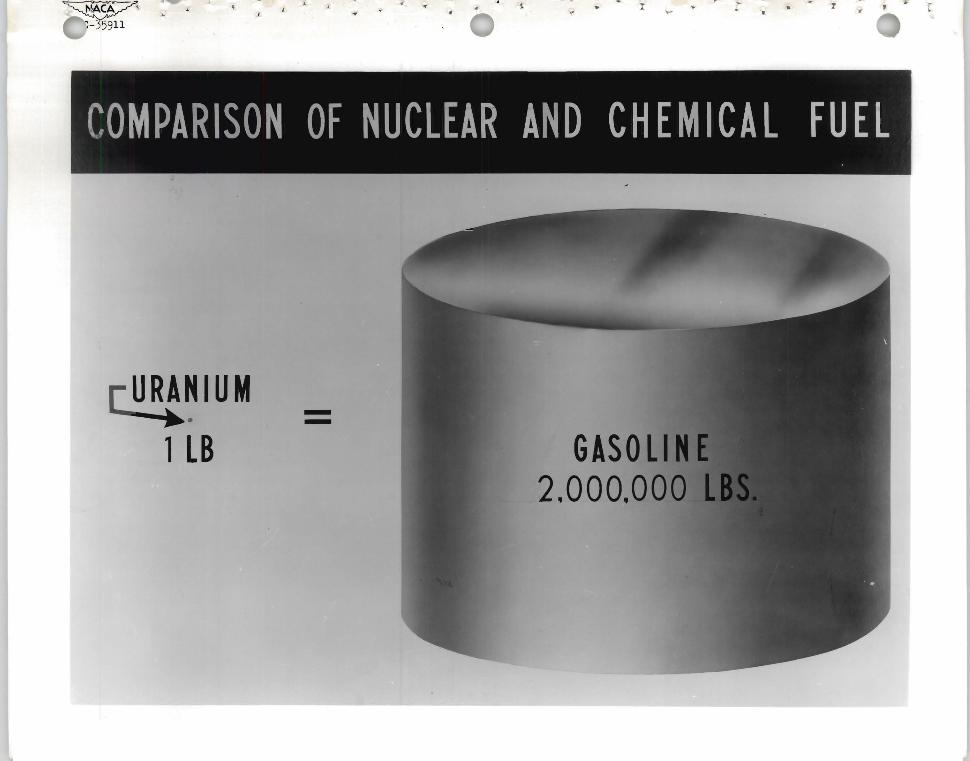
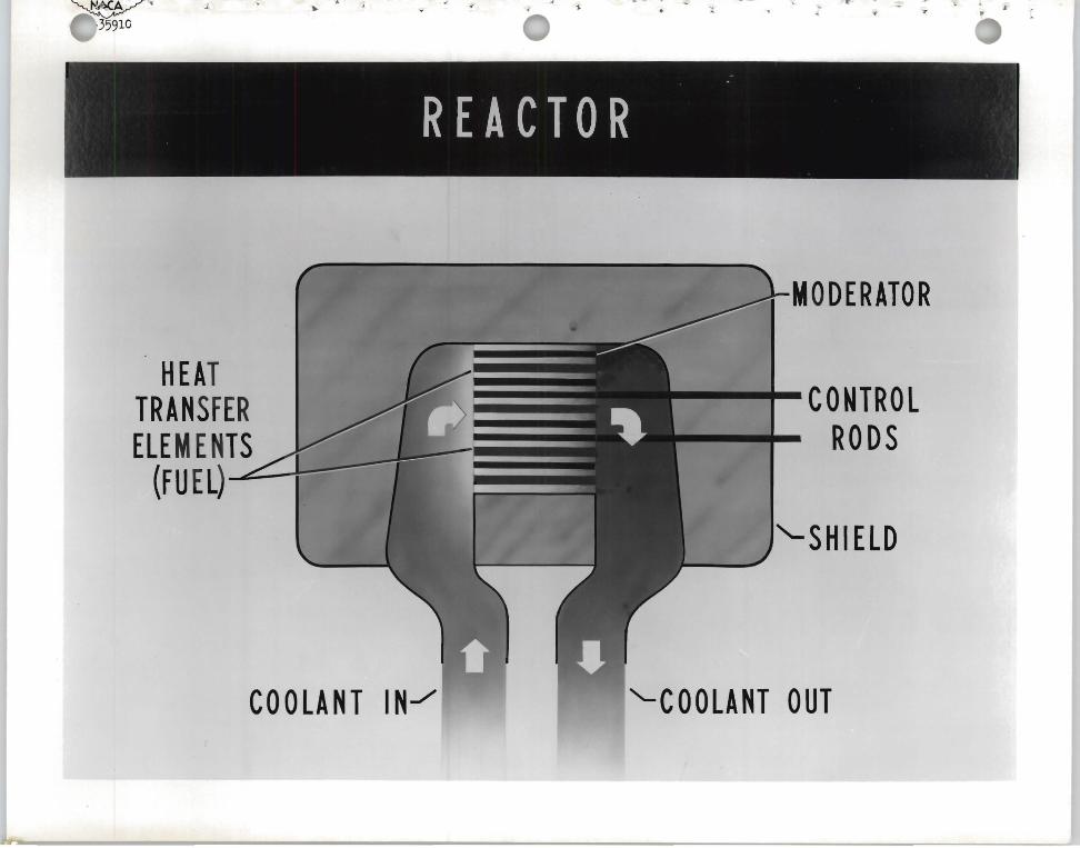
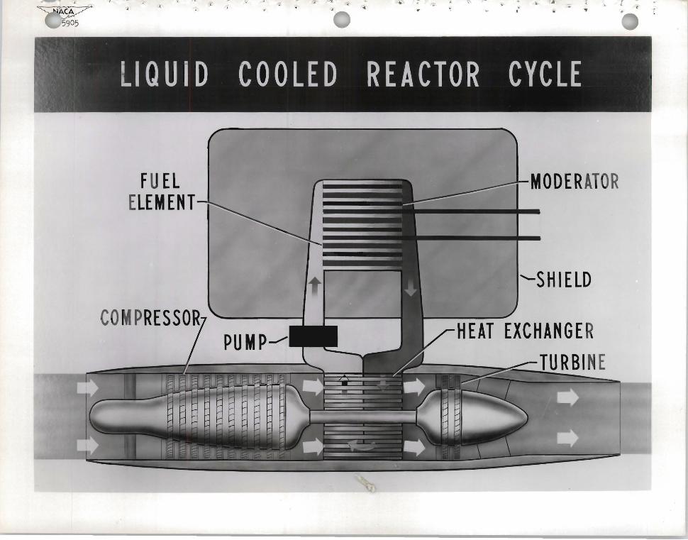

~o OOll
~o 009l
~o OOll
aWO~A3NOH 3HVnOS S31Yld IV1~
106~pound-C 2V)VMY bull e ft lt
~ - ~ 4 ~ shy l
CAPTURE CROSS SECTIONS OF REPRESENTATIVE MATERIALS
ALUMINUM 022 STRUCTURAL MATERIALS
IRON 24
COBALT 360
CONTROL ROD BORON 7500 MATE RIALS CADMIUM 24000
SO DIU M 049 COOLANTS WATER 064
LITHIUM 650
Sf
l V13W NOIIVHI3N3d H3AVl IN 3 H Vd HVlnNVH9H3INI N01 SO H H O~
I--I--I -I
INV100J V AS SlVIH31VW lVHnlJnH1S ~O NOISOHHOJ
J f bull 1 ~ ~ I r
MOl ~
l OH 1003 aI n1 ~
(J3 11 S0d30
INV1003 V AS SlVIH31VW lVHn13nH1S ~O H3~SNVHl SSVW
1 ~ bull
---
middot
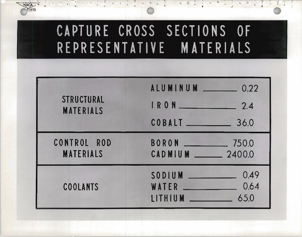
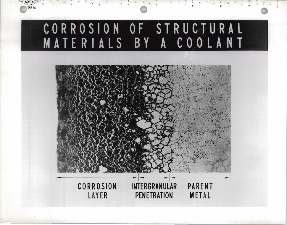
Sf
l V13W NOIIVHI3N3d H3AVl IN 3 H Vd HVlnNVH9H3INI N01 SO H H O~
I--I--I -I
INV100J V AS SlVIH31VW lVHnlJnH1S ~O NOISOHHOJ
J f bull 1 ~ ~ I r
MOl ~
l OH 1003 aI n1 ~
(J3 11 S0d30
INV1003 V AS SlVIH31VW lVHn13nH1S ~O H3~SNVHl SSVW
1 ~ bull
---
middot
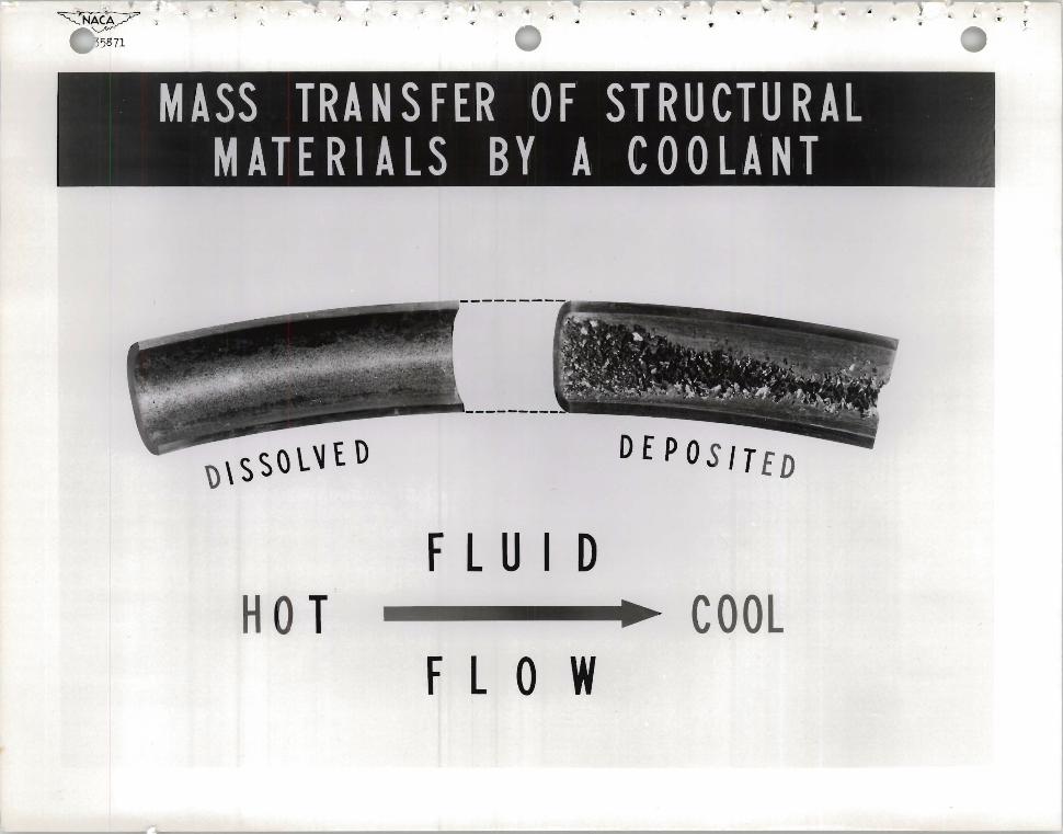
MOl ~
l OH 1003 aI n1 ~
(J3 11 S0d30
INV1003 V AS SlVIH31VW lVHn13nH1S ~O H3~SNVHl SSVW
1 ~ bull
---
middot